Falcon 345 - To scan DATALOGIC - Free user manual and instructions
Find the device manual for free Falcon 345 DATALOGIC in PDF.

| Product Type | Portable handheld scanner |
| Brand | Datalogic |
| Model | Falcon 345 |
| Dimensions | Approx. 200 x 80 x 40 mm |
| Weight | Approx. 400 g |
| Power Source | Rechargeable lithium-ion battery |
| Battery Life | Up to 10 hours of continuous use |
| Charging Time | Approx. 4 hours |
| Interface Options | USB, Bluetooth, RS-232 |
| Scan Capability | 1D and 2D barcodes |
| Decoding Technology | Advanced decoding for damaged codes |
| Display | Backlit LCD, 128x64 pixels |
| Keypad | Alphanumeric keypad with 28 keys |
| Drop Specification | Withstands multiple drops from 1.5 m to concrete |
| IP Rating | IP65 (dust and water resistant) |
| Operating Temperature | -20°C to 50°C |
| Storage Temperature | -30°C to 70°C |
| Cleaning Instructions | Clean scan window with a soft, dry cloth; avoid solvents |
| Safety Certifications | CE, FCC, RoHS |
| Spare Parts Available | Battery pack, charging cradle, cables, power adapter |
| Repairability | Serviceable by authorized centers; replaceable battery |
| Operating System | Windows Embedded CE 6.0 or Linux |
Frequently Asked Questions - Falcon 345 DATALOGIC
User questions about Falcon 345 DATALOGIC
0 question about this device. Answer the ones you know or ask your own.
Ask a new question about this device
Download the instructions for your To scan in PDF format for free! Find your manual Falcon 345 - DATALOGIC and take your electronic device back in hand. On this page are published all the documents necessary for the use of your device. Falcon 345 by DATALOGIC.
USER MANUAL Falcon 345 DATALOGIC
natural_image
Set of six black-and-yellow industrial mobile phone models with various function buttons and control knobs, arranged in a row (no visible text or labels)Advanced User's Guide
PSC Inc
959 Terry Street
Eugene, Oregon 97402
Telephone: (541) 683-5700
Fax: (541) 345-7140
An Unpublished Work - All rights reserved. No part of the contents of this documentation or the procedures described therein may be reproduced or transmitted in any form or by any means without prior written permission of PSC Inc. or its wholly owned subsidiaries ("PSC"). Owners of PSC products are hereby granted a non-exclusive, revocable license to reproduce and transmit this documentation for the purchaser's own internal business purposes. Purchaser shall not remove or alter any proprietary notices, including copyright notices, contained in this documentation and shall ensure that all notices appear on any reproductions of the documentation.
Should future revisions of this manual be published, you can acquire printed versions by contacting PSC Customer Administration. Electronic versions may either be downloadable from the PSC web site (www.pscnet.com) or provided on appropriate media. If you visit our web site and would like to make comments or suggestions about this or other PSC publications, please let us know via the "Contact PSC" page.
Disclaimer
Reasonable measures have been taken to ensure that the information included in this manual is complete and accurate. However, PSC reserves the right to change any specification at any time without prior notice.
PSC is a registered trademark of PSC Inc. The PSC logo is a trademark of PSC. All other trademarks and trade names referred to herein are property of their respective owners.
Falcon ^® is a registered trademark of PSC Inc. or one of its wholly owned subsidiaries.
PhoenixCARD Manager Plus © 1993, 1994 Phoenix Technologies Ltd.
This product may be covered by one or more of the following patents: 4603262 • 4639606 • 4652750 • 4672215 • 4699447 • 4709195 • 4709369 • 4749879 • 4792666 • 4794240 • 4798943 • 4799164 • 4820911 • 4845349 • 4861972 • 4861973 • 4866257 • 4868836 • 4879456 • 4939355 • 4939356 • 4943127 • 4963719 • 4971176 • 4971177 • 4991692 • 5001406 • 5015831 • 5019697 • 5019698 • 5086879 • 5115120 • 5144118 • 5146463 • 5179270 • 5198649 • 5200597 • 5202784 • 5208449 • 5210397 • 5212371 • 5212372 • 5214270 • 5229590 • 5231293 • 5232185 • 5233169 • 5235168 • 5237161 • 5237162 • 5239165 • 5247161 • 5256864 • 5258604 • 5258699 • 5260554 • 5274219 • 5296689 • 5298728 • 5311000 • 5327451 • 5329103 • 5330370 • 5347113 • 5347121 • 5371361 • 5382783 • 5386105 • 5389917 • 5410108 • 5420410 • 5422472 • 5426507 • 5438187 • 5440110 • 5440111 • 5446271 • 5446749 • 5448050 • 5463211 • 5475206 • 5475207 • 5479011 • 5481098 • 5491328 • 5493108 • 5504350 • 5508505 • 5512740 • 5541397 • 5552593 • 5557095 • 5563402 • 5565668 • 5576531 • 5581707 • 5594231 • 5594441 • 5598070 • 5602376 • 5608201 • 5608399 • 5612529 • 5629510 • 5635699 • 5641958 • 5646391 • 5661435 • 5664231 • 5666045 • 5671374 • 5675138 • 5682028 • 5686716 • 5696370 • 5703347 • 5705802 • 5714750 • 5717194 • 5723852 • 5750976 • 5767502 • 5770847 • 5786581 • 5786585 • 5787103 • 5789732 • 5796222 • 5804809 • 5814803 • 5814804 • 5821721 • 5822343 • 5825009 • 5834708 • 5834750 • 5837983 • 5837988 • 5852286 • 5864129 • 5869827 • 5874722 • 5883370 • 5905249 • 5907147 • 5923023 • 5925868 • 5929421 • 5945670 • 5959284 • 5962838 • 5979769 • 6000619 • 6006991 • 6012639 • 6016135 • 6024284 • 6041374 • 6042012 • 6045044 • 6047889 • 6047894 • 6056198 • 6065676 • 6069696 • 6073849 • 6073851 • 6094288 • 6112993 • 6129279 • 6129282 • 6134039 • 6142376 • 6152368 • 6152372 • 6155488 • 6166375 • 6169614 • 6173894 • 6176429 • 6188500 • 6189784 • 6213397 • 6223986 • 6230975 • 6230976 • 6237852 • 6244510 • 6259545 • 6260763 • 6266175 • 6273336 • 6276605 • 6279829 • 6290134 • 6290135 • 6293467 • 6303927 • 6311895 • 6318634 • 6328216 • 6332576 • 6332577 • 6343741 • 6,568,598• ^ , ^ , ^ , ^ , ^ , ^ , ^ , ^ , ^ , ^ , ^ , ^ , ^ , ^ , ^ , ^ , ^ , ^ , ^ , ^ , ^ , ^ , ^ , ^ , ^ , ^ , ^ , ^ , ^ , ^ , ^ , ^ , ^ , ^ , ^ , ^ , ^ , ^ , ^ , ^ , ^ , ^ , ^ , ^
CONTENTS
About this Guide ix
Overview....x
Falcon® Model Numbers ......x
Radio Frequency Interference....xii
Style Conventions...... xiii
Document Conventions ...... xiii
Keys and Keystroke Conventions ...... xiii
Technical Support ......xiv
Chapter 1: Using Falcon DOS Portable Terminals 1-1
Overview 1-2
Programming the Laser Triggers.... 1-2
Programming the Enter Keys....1-3
Using PC Cards.... 1-4
Opening the PC Card Slot Cover....1-5
Inserting a PC Card....1-6
Card Recognition and Configuration 1-7
Removing a PC Card 1-8
The Serial Port 1-8
The IR Serial Port 1-8
The Disk Drives 1-9
Configuring the Falcon....1-10
Transferring Files....1-11
An Example....1-12
Chapter 2: The Falcon Configuration Utility ...... 2-1
Overview 2-2
Installing the Falcon Configuration Utility....2-2
Using the Falcon Configuration Utility 2-3
Main Menu 2-3
The Custom Configuration Menu.... 2-5
The File Configuration Windows.... 2-9
The Program Settings Windows 2-16
The Comm Settings Dialog Box.... 2-20
The File Transfer Window 2-21
Chapter 3: Using File Transfer Programs....3-1
XFER32Using XFER32....3-2
XFER32XFER32 Setup.... 3-2
General Tab.... 3-3
Transfer Tab.... 3-5
Logging Tab 3-7
Host Mode 3-8
Sending and Receiving Data 3-8
Send File (to Portable).... 3-9
Receive File (from Portable).... 3-9
Using XFER 3-10
Syntax and Parameters.... 3-11
The XFER_ARGS Environment Variable.... 3-26
Multiple-Option Blocks 3-27
The Modem-Initialization File.... 3-29
Performance 3-32
Error Codes 3-34
Chapter 4: The Falcon 4-Slot Dock .... 4-1
Overview 4-2
Operating Modes....4-2
The 4SLOT.SYS Device Driver....4-3
Transferring Files with XFER 4-4
Setting the Baud Rate 4-5
Chapter 5: Disk Drives, Organization, Software, & Configurations...... 5-1
Overview 5-2
Disk Drives and Files....5-2
Structure.... 5-2
Drive A....5-3
Drive B....5-4
Drive C.... 5-6
Drive D 5-6
Additional Drives.... 5-7
Other System Software.... 5-7
BIOS and DOS 5-7
PC Card and RF Networking Software 5-8
System Configurations 5-8
Default Configuration 5-8
I/O PC Card Support Configuration 5-9
Chapter 6: System Utilities 6-1
Chapter Conventions.... 6-2
CFGDEV.SYS 6-3
CFGIO.EXE 6-4
COMIO.COM....6-5
DECODE.SYS 6-6
FLASHDSK.SYS 6-7
FORMAT.COM 6-8
LOCK.COM....6-9
ORGANIZE.COM 6-10
PM.COM....6-11
VDISK.SYS 6-13
XFER.EXE....6-14
Chapter 7: Resetting the Falcon....7-1
Overview....7-2
Warm Boot....7-2
Cold Boot 7-3
Safe Boot....7-4
Hardware Reset 7-5
Chapter 8: Using PC Cards....8-1
Overview....8-2
Uses of PC Cards....8-2
PC Card Drivers 8-3
Appendix A: Connector Configurations ...... A-1
Overview....A-2
Falcon Portable Terminals ......A-2
Laser-Scanner Connector....A-2
Serial Port Jack....A-3
Serial IR Port....A-4
Falcon Dock A-5
25-Pin Connector....A-5
Falcon 4-Slot Dock....A-6
Host-Interface Cable ......A-7
Dock-Network Cable Jacks....A-7
Appendix B: ROM-DOS Commands ......B-1
Command Overview...... B-2
ROM-DOS vs. MS-DOS ...... B-4
Command Descriptions...... B-5
ATTRIB B-6
BUFFERS...... B-7
CHKDSK...... B-8
COMMAND B-9
DELTREE...... B-11
DIR......B-12
FCBS...... B-14
FIND B-15
HELP B-16
NEWFILE...... B-16
PRINT B-17
SHARE...... B-19
SWITCHES B-20
TREE B-20
VER....B-21
XCOPY B-22
Appendix C: Programming Parameters ......C-1
Overview C-2
Code 39......C-3
Interleaved 2 of 5....C-3
Matrix 2 of 5....C-3
Standard 2 of 5 ....C-3
Code 11....C-4
Codabar/Ames C-4
MSI C-4
Code 93....C-4
Universal Product Code-A (UPC-A)......C-4
Universal Product Code-E (UPC-E)......C-5
European Article Numbering (EAN) /
Japan Article Numbering (JAN)......C-5
UPC, EAN, JAN Extensions....C-5
Code 128 C-5
Labelcode 4/5.....C-5
Other Controls ....C-5
Appendix D: Bar Codes ...... D-1
Predefined Defaults...... D-2
Code 39 D-2
ENABLE ....D-2
MINIMUM LENGTH...... D-2
MAXIMUM LENGTH ....D-2
ENABLE CHECKSUM......D-2
SEND CHECKSUM D-2
FULL ASCII MODE ...... D-2
Interleaved 2 of 5 D-3
ENABLE ....D-3
MINIMUM LENGTH...... D-3
MAXIMUM LENGTH ......D-3
ENABLE CHECKSUM......D-3
SEND CHECKSUM D-3
USE LENGTHS 6 AND 14 ONLY (case code) ...... D-3
Matrix 2 of 5 D-3
ENABLE D-3
MINIMUM LENGTH...... D-4
MAXIMUM LENGTH ......D-4
Standard 2 of 5 D-4
ENABLE ....D-4
MINIMUM LENGTH...... D-4
ENABLE CHECKSUM....D-4
SEND CHECKSUM D-4
MAXIMUM LENGTH ......D-5
ENABLE CHECKSUM......D-5
SEND CHECKSUM D-5
Code 11 D-5
ENABLE ....D-5
MINIMUM LENGTH...... D-5
USE 2-BAR START/STOP...... D-5
Codabar/Ames D-6
CODABAR ENABLE D-6
AMES ENABLE....D-6
MINIMUM LENGTH..... D-6
MAXIMUM LENGTH ...... D-6
MAXIMUM LENGTH ...... D-6
REQUIRE 2 CHECK DIGITS ...... D-6
SEND CHECK DIGIT(S)...... D-6
MSI D-7
ENABLE D-7
MINIMUM LENGTH..... D-7
MAXIMUM LENGTH D-7
SEND STOP/START...... D-7
CODABAR-TO-CLSI CONVERSION...... D-7
WIDE INTERCHARACTER GAPS ALLOWED ...... D-7
Code 93 ......D-8
ENABLE D-8
MINIMUM LENGTH..... D-8
MAXIMUM LENGTH D-8
REQUIRE 2 CHECK DIGITS ...... D-8
2ND CHECK DIGIT MOD 11 ...... D-8
SEND CHECK DIGIT(S)...... D-8
Code 128 ....D-8
ENABLE D-8
MINIMUM LENGTH..... D-9
MAXIMUM LENGTH D-9
Labelcode 4/5 ......D-9
ENABLE D-9
CONVERT...... D-9
UPC-A (Universal Product Code-A) ......D-9
ENABLE UPC-A D-9
ENABLE UCC/EAN 128 D-9
UPC-E (Universal Product Code-E)......D-10
USE SYSTEM DIGIT 0 ...... D-10
USE SYSTEM DIGIT 1 ...... D-10
CONVERT UPC-E TO UPC-A ...... D-10
SEND SYSTEM DIGIT D-10
SEND CHECK DIGIT D-10
SEND SYSTEM DIGIT D-10
SEND CHECK DIGIT ...... D-10
CONVERT UPC-A TO EAN-13...... D-10
EAN (European Article Numbering)/ JAN (Japan Article Numbering) ...... D-10
ENABLE EAN-8/JAN-8 D-10
UPC/EAN/JAN Extentions ....D-11
ALLOW 2-DIGIT EXTENSIONS...... D-11
ALLOW 5-DIGIT EXTENSIONS...... D-11
REQUIRE EXTENSIONS ...... D-11
ENABLE EAN-13/JAN-13 D-11
CONVERT EAN-13 TO ISBN...... D-11
SEND EAN/JAN CHECKSUM...... D-11
Other Controls ...... D-11
AUTOTERMINATOR ....D-11
AUTO-OFF TIMER......D-11
SEND SYMBOLOGY IDENTIFIER ...... D-12
GOOD-READ BEEP TONE (in Hertz)......D-12
NUMBER OF GOOD-READ BEEPS ...... D-12
GOOD-READ BEEP DURATION ...... D-12
BEEPER VOLUME......D-12
ERROR BEEP TONE (in Hertz)......D-13
LONG-RANGE TRIGGER MODE ...... D-13
SPOTTING BEAM ENABLE D-13
SPOT BEAM TIMEOUT (in seconds)......D-13
RELEASE SCAN TIMEOUT (in seconds)......D-13
KEYPRESS SOUND...... D-13
ENABLE CTL-ALT-DEL REBOOT...... D-13
ENABLE TRIGGER PROGRAMMABILITY...... D-14
BACKLIGHT AUTO-OFF TIMEOUT......D-14
DOUBLE KEY ACTION MODE...... D-14
DOUBLE KEY ACTION TIMEOUT D-14
Index......XV
NOTES
Preface:
About this Guide
PREFACE CONTENTS
Overview ...... viii
Falcon ^® Model Numbers ...... viii
Radio Frequency Interference....x
Style Conventions.... xi
Document Conventions xi
Keys and Keystroke Conventions.... xi
Technical Support ...... xii
Overview
This manual is a supplement to the Falcon ^® DOS Portable Terminals User's Guide. It contains the following technical information on Falcon portables:
- System configuration
- Disk drives
• Using PC cards - Resetting the Falcon
• Using the 4-Slot Dock - DOS commands
- Utilities
- Connector configurations
- Programming parameters
• Bar codes for setting parameters
This book is provided as a reference guide for System administrators, Developers, and Programmers who want to create end-user solutions for Falcon DOS portable terminals. It is not intended for use by first-time Falcon users.
Falcon® Model Numbers
Falcon DOS portable data terminals are handheld computers designed for data collection. The product title, "Falcon" refers to any or all of the DOS portable models identified in the table below of Falcon® Portable Models.
Where information in this manual applies only to specific models, those models are clearly identified by the model icon as shown in the first column.
The Falcon DOS portable line includes 8-line and 16-line models. Both the 8-line and the 16-line Falcon models are available in batch and wireless (radio frequency, or RF) configurations. Wireless models provide instant communication of data between the unit and a host computer.
Table 1: Falcon ^® Portable Models
| Model | Model Number | 8-Line Display | 16-Line Display | Batch Portable | RF Portable |
| 31X | 310 | ◆ | ◆ | ||
| 315 | ◆ | ◆ | |||
| 32X | 320 | ◆ | ◆ | ||
| 325 | ◆ | ◆ | |||
| 33X | 330 | ◆ | ◆ | ||
| 335 | ◆ | ◆ | |||
| 34X | 340 | ◆ | ◆ | ||
| 345 | ◆ | ◆ |
31X The 31X icon refers to both the Falcon 310 and the Falcon 315. As the table on page xi notes, the Falcon 310 is a batch portable model and the Falcon 315 is an RF portable model. On the cover of this manual, the Falcon 31X is represented by the Falcon 315, in the lower left corner, with an 8-line display screen.
32X The 32X icon refers to both the Falcon 320 and the Falcon 325. As the table on page xi notes, the Falcon 320 is a batch portable model and the Falcon 325 is an RF portable model. The Falcon 32X has many features in common with the Falcon 31X. These models are often grouped together throughout this manual. On the cover of this manual, the Falcon 32X is represented by the Falcon 325, second from the upper left, with a 16-line display screen.
33X The 33X icon refers to both the Falcon 330 and the Falcon 335. As the table on page xi notes, the Falcon 330 is a batch portable model and the Falcon 335 is an RF portable model. The Falcon 33X model has many features in common with the Falcon 32X model. On the cover of this manual, the Falcon 330 portable is the smaller, ergonomic model shown in the upper right corner of the grouping.
34X
The 34X icon refers to both the Falcon 340 and the Falcon 345. As the table on page xi notes, the Falcon 340 is a batch portable model and the Falcon 345 is an RF portable model. The Falcon 34X introduces the pistol grip. This model operates in every other way identically to the Falcon 33X. On the cover of this manual, the Falcon 340 portable is the one with the pistol grip, shown in the lower right corner of the grouping.
Radio Frequency Interference
This device complies with Part 15 of the FCC Rules. Operation is subject to the following two conditions:
-
This device may not cause harmful interference, and
-
This device must accept any interference received, including interference that may cause undesired operation.
This Class A digital apparatus complies with Canadian ICES-003.
This equipment has been tested and found to comply with the limits for a Class A digital device, pursuant to Part 15 of the FCC Rules. These limits are designed to provide reasonable protection against harmful interference in a residential installation. This equipment generates, uses and can radiate radio frequency energy and, if not installed and used in accordance with these instructions, may cause harmful interference to radio communications.
However, there is no guarantee that interference will not occur in a particular installation. If this equipment does cause interference to radio or television reception, which can be determined by turning the equipment off and on, the user is encouraged to try to correct the interference by one or more of the following measures:
• Reorient or relocate the receiving antenna.
- Increase the separation between the equipment and receiver.
- Connect the equipment into an outlet on a circuit different from which the receiver is connected.
- Consult the dealer or an experienced radio/TV technician for help.
Style Conventions
Document Conventions
Formatting conventions are used throughout this guide as a method of providing consistency for notes, cautions, and warnings.
Notes

Notes appear throughout the manual to provide additional information on a topic, including technical details, exceptions to instructions and other pertinent information. These notes are identified by the notepad symbol to the right and bold italics text.
Cautions

Cautions appear when there is information for the user that is strongly recommended. They are identified by the exclamation mark in a triangle and bold italics text. This text appears in gold bold italics text if the user is viewing the manual in electronic PDF form on their computer.
Warnings

Warnings appear when there is something of extreme importance for the user to be known prior to proceeding. They are identified by the exclamation mark in a triangle and bold italics text. This text appears in red bold italics text if the user is viewing the manual in electronic PDF form on their computer.
Keys and Keystroke Conventions
Portable keys and keystroke conventions are used throughout this manual to identify the difference between a key on the portable and keystrokes input by the user. Brackets such as: "
Technical Support
PSC Website Technical Support
The most comprehensive source for technical support and information for PSC products is the PSC website: www.pscnet.com. Select Support from the sidebar for technical support. The site offers product registration, warranty information, answers to frequently asked questions (product FAQs), product manuals, product tech notes, software updates, patches, demos, and instructions for returning products for repair.
Reseller Technical support
Another excellent source for technical assistance and information is an authorized PSC reseller. A reseller is directly acquainted with specific types of businesses, application software, and computer systems and, therefore, is in the best position to provide individualized assistance.
E-Mail Technical Support
If the solution to a technical support question is not available through the PSC website or a local reseller, contact PSC technical support directly via E-mail at TechSupport@pscnet.com.
Telephone Technical Support
For those without E-mail access, please call (541) 984-3092.
PSC Solutions Group
For advanced, cost-effective services, contact the PSC Solutions Group (PSG) at (888) 583-3008 or psg@pscnet.com. Or go to the PSG webpage at www.pscnet.com/html/psc_solutions_group_psg.htm.
1
Using Falcon DOS Portable Terminals
CHAPTER CONTENTS
Overview....1-2
Programming the Laser Triggers....1-2
Programming the Enter Keys....1-3
Using PC Cards 1-4
Opening the PC Card Slot Cover 1-5
Inserting a PC Card....1-6
Card Recognition and Configuration....1-7
Removing a PC Card....1-8
The Serial Port....1-8
The IR Serial Port....1-8
The Disk Drives....1-9
Configuring the Falcon....1-10
Transferring Files 1-11
An Example....1-12
Overview
This chapter provides information about advanced features of Falcon DOS portable terminals. It does not cover Falcon basics, such as use of the keypad and viewport. For basic information about the Falcon, refer to the Falcon DOS Portable Terminals User's Guide.
Programming the Laser Triggers
31X 32X
Normally, the left trigger operates the Falcon laser or another bar code reader attached to the Falcon, and the right trigger toggles the Falcon in and out of Alpha mode (models 31x) or Function mode (models 32x). One or both of the laser triggers can be reprogrammed to act as equivalents of keypad keys.
To turn a trigger into an alias for a keypad key:
31X
- Hold down the
and keys. - Press the
key and the program-trigger cursor (p) appears in the viewport. - Press the trigger to be changed.
- Press the key to be assigned to the trigger. The following keys are valid selections:
-
First, hold down the
and keys and press the key. The program-trigger icon (t) should appear in the viewport. -
Press the trigger that is to be changed.
-
Press the new key assigned to the trigger. The following keys are valid selections:
For example, to turn the right trigger on a model 32x into an alias for the
- Hold down the
and keys and press the key to enter program-trigger mode. - Then press and release the right trigger.
- Press the
key.
The right trigger now works as a second
To change a reassigned trigger back to a laser trigger:
- Put the Falcon into program-trigger mode.
- Press the trigger twice.


Falcon 33x and 34x models do not have programmable laser triggers. The
Programming the Enter Keys

Falcon 33x and 34x models allow reprogramming of one of the

This features only is only available on a 38-key keypad.
Figure 1-1: Location of the Enter keys on the Falcon 33X and 34X

text_image
F8 F7 F8 F9 F'0 F1 F2 F3 F4 F5 Enter Scan Enter Home △ PaUp 7 8 9To program an
- Hold down the key sequence key to re-program.

Press the
- The Program Trigger Icon (or) appears on the right of the LCD, indicating which
key is to be reprogrammed. - Select the key sequence to reprogram the
key. The following keys are valid sections:
<Backspace> <Enter> <Tab>
<Caps> <Intl>

All of these functions, except the
Using PC Cards
31X 32X
The Falcon has a slot for plugging in PC cards, and each unit is factory-equipped with PhoenixCARD Manager Plus PC card drivers. PC cards provide such features as network connectivity, modem connectivity, and wireless capability. Their primary purpose in the Falcon is to provide additional memory storage by functioning as a disk drive. (See page page 1-9 for information about the Falcon's drives.)
33X 34X

The PC card slots of the Falcon 33x and 34x are not user accessible, but function in the same manner as the Falcon 32x for software installation, use and general features.
Opening the PC Card Slot Cover

The PC card slot is located near the bottom on the back of the Falcon (refer to Figure 1-2). The slot is protected by a cover. Detach the elastic hand strap on the back of the Falcon by pulling its hook out of the holder near the base. If the slot cover is secured by a screw, loosen the screw. Then, while pressing the round button above the slot cover, slide the cover out and away from the Falcon.
Figure 1-2: Removing the PC Card Slot Cover on a Falcon 310

text_image
1. Remove the hand strap hook from the holder (hand strap not shown). 2. Loosen the locking screw.* 3. Press the round button to release the cover. 4. Pull the cover out. ③ ② ① ④ *The locking screw cannot be completely removed from the PC card slot cover. To keep the screw from catching on the unit, turnInserting a PC Card
31X 32X
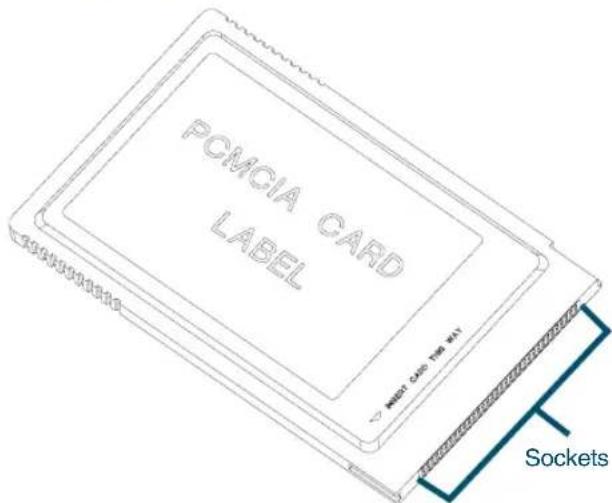
All PC cards have two rows of small sockets on one end (refer to Figure 1-3). The cards also have face-up and face-down sides. The card manufacturer's label is usually on the face-up side.

Turn the Falcon off before inserting or removing a PC card.
Figure 1-3: A Typical PC Card
text_image
POMCIA CARD LABEL MOST CARD THE WAY SocketsTo insert a PC card into a Falcon complete the following steps:
- Start with the Falcon face down and the PC card face up.
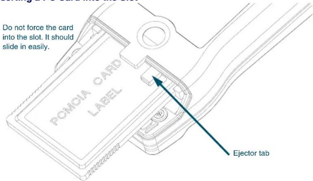
- Insert the end of the card with the sockets into the card slot (refer to Figure 1-4).
- Use the tracks inside the slot to help guide the card.
- Push the card firmly into the slot until the ejector tab slides out.
- Replace the PC card slot cover.
Figure 1-4: Inserting a PC Card into the Slot
text_image
Do not force the card into the slot. It should slide in easily. PCMCIA CARD LABEL Ejector tab
The PC card slot on the Falcon is designed so a card cannot be inserted upside down or backward. If the card does not push into the slot easily, make sure the card is positioned properly. Put the end with the sockets into the slot first. Then flip the card upside down and try to insert it again.
Card Recognition and Configuration
Once the card is inserted into the slot complete the following steps:
- Turn the Falcon on. The Falcon will attempt to recognize and configure the card.
- If the Falcon responds with one beep, the PhoenixCARD Manager Plus drivers successfully recognized and configured the card.
- If the Falcon does not beep, the drivers might not be loaded in the Falcon, or the beeper may be disabled.

In some cases, drivers provided by a specific card's vendor are responsible for configuring the card. If one of these cards is being used, there may be no audio signals for card configuration. See the configuration instructions that came with the card.
Removing a PC Card
A tab inside the PC card slot ejects the installed card (refer to Figure 1-4). Push the end of the ejector tab into the Falcon. The PC card should slide partway out of the slot. Hold the card by the edges and pull it the rest of the way out.
The Serial Port
31X 32X
Falcon models 31x and 32x have a port for serial communications with a PC. The serial port is located at the base of the Falcon 31x and 32x (refer to Figure 1-5). Designated as COM1, it is a 10-pin telephone-style jack providing a standard RS-232 connection.
With a serial cable connected to it, the port allows communications with a host computer or any serial device, such as a printer or modem. The serial port also provides a connection for communications and battery recharging in the Falcon Dock and Falcon 4-Slot Dock.
Figure 1-5: The Serial Port on a Falcon 320
31X 32X

text_image
8 M AN AN SD P S S L I U V W X AD AD AD AD AD AD AD AD A A A A A A A A A A A A A A A A A A A A A A A A A A A A A A A A A A A A A A A A A A A A A A A A A A 10000000000000000000000000000000000000000000000000000000000000000000000000000000000000For the wiring configuration of the serial port, refer to Appendix A, on page A-1.
The IR Serial Port
33X 34X
The serial port of the Falcon 33x and 34x is a half duplex IR port. Refer to Figure 1-6. Through software commands, the port may be setup for IR or a modified RS-232 serial communication.
- In IR mode, all physical communications meet the IrDA physical layer specification.
- In the modified RS-232 serial mode, the IR port is used to transmit RS-232 level data out the IR port. The third pin along the bottom of the Falcon 33x and 34x is used to receive RS-232 level data.
- In general, the IR mode is used when communicating to other IR devices (printers, computers, etc.) and the modified RS-232 mode is used to communicate with the dock for host communications.
- The Falcon 33x and 34x do not propagate the RS-232 hardware signals such as RTS, CTS, DTR, DSR, RI, and DCD.

When using Zmodem, flow control must be the same on both sides of the transmission. Normally, XFER defaults to RTS/CTS flow control. On the Falcon 33x and 34x, it defaults to Xon/Xoff. When transferring files between a 33x or 34x and the host PC, make sure the PC is also using Xon/Xoff. See the /F option on page 3-18 for more details.
Figure 1-6: The IR Serial Port on the Falcon 33x and 34x

natural_image
Technical line drawing of a mechanical component with a blue circular highlight (no text or symbols)The Disk Drives
The Falcon contains four logical disk drives that provide storage for system files, applications, and data.
Drive A Drive A is a read-only drive. Its contents cannot be changed.
Drive B Drive B is a read-only drive used to store system utilities and to initialize the boot process. Its contents cannot be changed.
Drive C Drive C is a flash disk drive that allows full read and write access. This drive contains DOS command files, PC card drivers, Falcon utilities, and executable files and associated files for applications. It may also contain additional config.sys and autoexec.bat files to configure the Falcon to run applications.
Drive D Drive D is a RAM disk drive. The RAM disk is used primarily for data storage. Programs that need to be loaded into memory and then quickly removed from memory can also be placed here. Drive D can also be used for scratch disk space or temporary files.
Additional DRives Additional RAM disk drives may be configured using VDISK.SYS. This can be done using the configuration utility (refer to page 2-12) or directly in CONFIG.SYS (refer to page 6-13.)

The Falcon may also be configured to use PC ATA flash cards. The PC Card is identified as a hard disk drive by the operating system. This drive may be used for safe and permanent storage of data.
The Falcon may have other additional logical drives that are network drives accessed via wireless access points.
The drive letters for the additional RAM, ATA, and network drives will be assigned at loading. The drive letters will begin at Drive E.
Configuring the Falcon
If the Falcon is not already configured, use the Falcon Configuration Utility to install applications and set options for bar code scanning. The Falcon Configuration Utility operates under Windows® 95, Windows® 98, Windows® 2000, Windows® ME, and Windows® NT. For instructions on using the utility, refer to Chapter 2.
Bar codes can also be used to change settings in the Falcon. Appendix D contains the bar codes for most common settings.
Transferring Files
To transfer data or program files, connect the Falcon unit to the host computer with any of the following accessories:
- Falcon serial cable
- Falcon Dock
- Falcon 4-Slot Dock (Only available for Falcon models 31x and 32x.)
The Falcon application may have simple file-transfer options, or use the Falcon XFER utility.
When using the Falcon Configuration Utility to transfer files (refer to Chapter 2), the configuration utility runs XFER automatically. If the configuration utility is not used, XFER requires entering commands at the DOS command line on both the Falcon and the PC.
Falcon and the PC.
The XFER utility is loaded into the Falcon at the factory and placed on drive B. If the PATH statement has not been changed, XFER can be run from any drive on the Falcon. However, before running XFER32 on a PC, install the Falcon Configuration Utility onto the hard drive. By default, XFER32xfer32 is placed in the directory: \PDTFiles
The command line syntax for XFER is as follows:
XFER [/option1 [/option2] ... ] filename
Use a slash (/) or a hyphen (−) to denote options, and use uppercase or lowercase letters. Options can be placed before or after the filename on the command line. A sample command line appears at the end of this section.
Transfer a single file by using XFER with the Xmodem protocol (the default protocol) or transfer multiple files with the Xmodem or Zmodem protocol.
Basic options for Xmodem protocol are listed and described in Table 1-1 on page 1-12. The “Default” column indicates whether the option is used (“On”) or ignored (“Off”) if not included in the command line. For options that have two or more possible values, the default value is given.
Table 1-1: XFER Options (Xmodem Protocol)
| Option What It Does Default | ||
| filename Identifies the file to be transferred or received. None | ||
| # | Specifies the communication port to use. Replace the # symbol with the desired setting:1 = COM1 2 = COM2 | 1 |
| B# | Specifies the baud rate. Replace the # symbol with the desired setting:2400 4800 9600 19200 38400 57600 115200 | 19200 |
| D# | Specifies the number of seconds for XFER to wait for activity before cancelling the transfer. Replace the # symbol with the desired number of seconds for the timeout delay. Acceptable values are 0 (no timeout) through 65, 535. | 60 |
| H or ? | Displays help for the XFER command. | Off |
| O | Overwrites an existing file with a new file having the same name. | Off |
| R | Receives the specified file. | Off |
| T | Transmits the specified file. | On |
An Example
To transfer a file named foo from a PC to a Falcon using Xmodem protocol, use the following command lines.
On the PC: xThe cfoo and causes the computer to send the specified file using XFER's default settings.
On the Falcon: xHerco/mfob causes the Falcon to receive the specified file transmitted from the PC.

For more information about XFER, including Zmodem options, refer to Chapter 3.
2
The Falcon Configuration Utility
CHAPTER CONTENTS
Overview....2-2
Installing the Falcon Configuration Utility .....2-2
Using the Falcon Configuration Utility .....2-3
Main Menu 2-3
The Custom Configuration Menu....2-5
The File Configuration Windows ......2-9
The Program Settings Windows....2-16
The Comm Settings Dialog Box 2-20
The File Transfer Window ......2-21
Overview
The Falcon Configuration utility provides a simple way to change the Falcon's settings for bar code symbologies and serial communications. It can also be used to load programs and files into the Falcon. The utility runs under Windows® 95, Windows® 98, Windows® 2000, Windows® Me, and Windows® NT. This chapter describes how to install the utility and use it to configure the Falcon.
Installing the Falcon Configuration Utility
To install the Falcon Configuration utility complete the following steps:
-
Insert the CD labeled PC's CD drive. Falcon Utility Software and Manuals into the
-
Wait for the autoplay to open. If the autoplay does not come up, access the CD using Windows Explorer. Go to the install directory and run setup.exe.
-
At the autoplay menu, select the Falcon Configuration utility.
-
Copy the file to your desktop or run it from the CD.
-
In the Installation Options window, select the radio components to be installed, if any.
-
Click on the Next button to continue.
-
In the RF Installation Options window, uncheck the check boxes for any components not to be installed.
-
Click on the Next button to continue to the next dialog box.
-
In the Select a Group Name window, select a program group in which to place the Falcon Configuration utility icons.
10.Click on the Next button to continue.
- Specify the directory in which to place the utility files in the next window. Falcon Configuration
12 Click on the Next button to continue.
-
Continue following the instructions in the dialog boxes, replacing the first disk with the second, and then the third disk.
-
When the installation is complete, click on the finish button in the final window.
Using the Falcon Configuration Utility

To start the Falcon Configuration utility, double-click on the FALCON icon in the program group. The first screen that appears is the main menu.
Main Menu
This menu provides access to all the configuration settings for the Falcon (Figure 2-1 on page 2-4).
Default
- Select this option to load the original factory configuration into the Falcon unit. The Configuration utility prepares files to be transferred to the Falcon and opens the Important dialog box (Figure 2-2).
- Check the file lists in both sections of the dialog box to see if they are correct and complete.
- To add, delete, or rename files, select Cancel from the dialog box.
- Use the Custom selection in the main menu to build custom lists. (Refer to page 2-5 through page 2-8 for instructions to create custom configurations.)
- If the file lists in the dialog box are correct, make sure the Falcon unit is properly connected to the serial port specified in the Comm Settings dialog box (refer to page 2-20).
- Run the ld.bat file on the Falcon.
Figure 2-1: The Falcon Configuration Utility Main Menu

text_image
Falcon Configuration Utility Default Quickly install default components. Custom Set up and install a custom configuration. Comm Settings Modify serial port settings. Transfer Files Transfer files to or from a portable unit. Select Product ○ Falcon 31x ○ Falcon 32x/33x/34x ○ Falcon 51x Help Exit- Click on the OK button in the Important dialog box (Figure 2-2 on page 2-5).
Custom Select this option to choose or modify configuration files or program files to be loaded into the Falcon unit. See the next section for information on the Custom Configuration menu.
Comm Settings Select this option to modify settings for the computer's serial port. Refer to page 2-20 for information on the Comm Settings dialog box.
Transfer Files Select this option to transfer data files between the Falcon and the host computer. Refer to page 2-21 through page 2-24 for information on the File Transfer window.
Figure 2-2: The Important Dialog Box

text_image
Important Verify the host-to-portable serial connection. Run LD.BAT on the portable. Select OK to start transfer. TEMP\RESPONSE.BAT is transferred to the portable and used by LD.BAT. The Host uses TEMP\DOWNLOAD.BAT. Serial Port: Com1 Baud Rate: 9600 Portable: Falcon 32x/33x/34x PC source files C:\Percon\Falcon\demo\upgstart.bat C:\Percon\Falcon\demo\pal2.bat C:\Percon\Falcon\demo\pal2.exe C:\Percon\Falcon\demo\DATETIME.BAT C:\Percon\Falcon\pcm\pcmata.sys C:\Percon\Falcon\pcm\cnfignam.exe C:\Percon\Falcon\pcm\pcmcs.exe Portable destination files c:\upgstart.bat c:\go.bat c:\pal2.exe c:\datetime.bat c:\pcm\pcmata.sys c:\pcm\cnfignam.exe c:\pcm\pcmcs.exe OK CancelSelect Product: Select the appropriate radio-button for type the Falcon model being configured: 31x, 32x/33x/34x, or 51x.
The Custom Configuration Menu
- Select Custom from the main menu.
-
An Open dialog box appears (refer to Figure 2-3 on page 2-6).
-
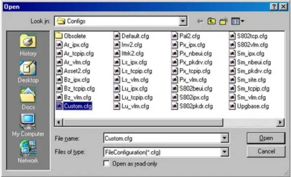
Use this dialog box to select a configuration file from the Configs folder.
- The configuration file contains the information presented when selecting the File Configuration button on the Custom Configuration menu.
Figure 2-3: The Open Dialog Box for Selecting a Configuration File
text_image
Open Look in: Configs History Desktop Docs My Computer Network Obsolete Ar_ipx.cfg Ar_tcpip.cfg Ar_vlm.cfg Asset2.cfg Bz_ipx.cfg Bz_tcpip.cfg Bz_vlm.cfg Custom.cfg Default.cfg Inv2.cfg Ittrk2.cfg Ls_ipx.cfg Ls_tcpip.cfg Ls_vlm.cfg Lu_ipx.cfg Lu_tcpip.cfg Lu_vlm.cfg Pal2.cfg Px_ipx.cfg Px_nbeui.cfg Px_pkdrv.cfg Px_tcpip.cfg Px_vlm.cfg S802tcp.cfg S802vlm.cfg Sm_ipx.cfg Sm_nbeui.cfg Sm_pkdrv.cfg Sm_site.cfg Sm_tcpip.cfg Sm_vlm.cfg S802px.cfg S802pkdr.cfg Upgbase.cfg File name: Custom.cfg Files of type: FileConfiguration(*.cfg) Open as read-only Cancel
If the Open as read-only check box is selected and changes are made to the configuration settings, use a new file name to save the changes.
- When the configuration file is finished loading, a second Open dialog box appears.
- Use this dialog box to select a program-settings file from the Progsets folder.
-
The program-settings file contains the information that will be presented when selecting the Program Settings button on the Custom Configuration menu.
-
After the program-settings file is loaded, the menu appears (Figure 2-4 on page 2-7). Custom Configuration
File Configuration Select this option to choose application files to be loaded into the Falcon. Refer to page 2-9 through page 2-16 for information about the File Configuration windows.
Configure Files Using: This field shows the configuration file that will be used to specify the files that will be loaded into the Falcon. Select the check box to load the files. Deselect it to turn this option off.
Figure 2-4: The Custom Configuration Menu

text_image
Custom Configuration File Configuration Configure Files Using : Custom.CFG Program Settings Program Settings Using : Custom.PRS Comm Settings Modify serial port settings. Download Download selection to portable unit. Select Product ● Falcon 31x ○ Falcon 32x/33x/34x ○ Falcon 51x Help DoneProgram Settings
Select this option to view or change settings for bar code symbologies and other programmable Falcon options. Refer to page 2-16 through page 2-20 for information about the Program Settings windows.
Program Settings Using: This field shows the program-settings file that will be used. Select the check box to load the program settings. Deselect it to turn this option off.
Comm Settings
Select this option to view or change serial communications settings for the Falcon. See page 2-20 for information about the Comm Settings dialog box.
Download
When finished customizing the Falcon configuration, select this option to load the custom configuration into the Falcon.
-
When selected, the configuration utility prepares files to be transferred to the Falcon and opens the Important dialog box (refer to Figure 2-2).
-
Make sure the Falcon unit is properly connected to the serial port specified in the Comm Settings dialog box (refer to page 2-20).
-
Then run the ld.bat file on the Falcon, and select OK in the Important dialog box.
Select Product: Select the appropriate radio-button for type the Falcon model being configured: 31x, 32x/33x/34x, or 51x.
Done Select this option to return to the main menu. If changes were made to the file configuration or program settings, one or both of the following prompts appear:
Figure 2-5: The Prompt for Saving Changes to the Current File Configuration

text_image
Save Configuration Do you wish to save this configuration to a file? Yes No CancelFigure 2-6: The Prompt for Saving Changes to the Current Program Settings

text_image
Save Program Settings Do you wish to save the program settings to a file? Yes No CancelYes Select this option to save the changes. A Save As dialog box will open. Use the dialog box to specify the location and name of the new configuration or program-settings file.
No Select this option to discard the changes.
Cancel Select this option to return to the saving or discarding the changes. Custom Configuration menu without
The File Configuration Windows
- Select File Configuration from the Custom Configuration Menu
- The first of three File Configuration windows appears. (Figure 2-7)
Figure 2-7: The First File Configuration Window

text_image
File Configuration Configuration File: Custom.CFG Save Browse... Main Application C:\Percon\Falcon\demo\upgstart.bat Add... Application Files custom.bat custom.exe DATETIME.BAT upgstart.bat Edit... Delete Select Product ○ Falcon 31x ○ Falcon 32x/33x/34x ○ Falcon 51x Help Next >> Done- Use these windows to choose application files to be loaded into the Falcon.
Configuration File: This field shows the configuration file used to specify the files that will be loaded into the Falcon.
Save After adding, editing, or deleting files in the Application Files list, select Save to save the revised list in the current configuration file or in a new one.
Browse 1. Select Browse to use a different configuration file.
-
An Open dialog box appears.
-
Use the Open dialog box to choose a configuration file from the Configs folder.
- If Browse is selected after making changes in this or any other File Configuration window and the changes are not saved, the prompt shown in Figure 2-8 appears.
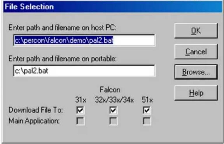
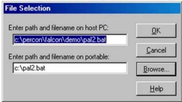
Figure 2-8: The File Selection Dialog Box for Adding an Application File
text_image
File Selection Enter path and filename on host PC: c:\percon\falcon\demo\pal2.bat Enter path and filename on portable: c:\pal2.bat Download File To: Main Application: 31x Falcon 32x/33x/34x 51x OK Cancel Browse... HelpMain Application: This field identifies the default application that will run on the Falcon after completing the installation.
Application Files: This field lists the files associated with the main application.
Add Select this option to include other files to be installed on the Falcon unit. The File Selection dialog box opens.
Enter path and filename on host PC: Use this field to specify the file to be transferred to the Falcon.
Enter path and filename on portable: Use this field to specify the location and name of the file to be transferred to the Falcon. The name can be the same as the original file or it can be given a new name.
Download File To: Select this check box to have the specified file downloaded to the specified Falcon models.
Main Application: Select this check box to have the specified file be the main application on the specified Falcon models.

Only one file can be selected as the main application for a Falcon model family. To select another file as the main application, highlight the current one in the Application Files list in the File Configuration window, select Edit, and turn off the Main Application switch for that file.
OK Select OK to return to the File Configuration window. The specified source file will appear in the Application Files list.
Cancel Select Cancel to return to the File Configuration window without adding a file to the Application Files list.
Browse 1. Select Browse to use a different configuration file.
- An Open dialog box appears.
- Use the Open dialog box to choose a source file to be included in the custom configuration.
Edit Select a file in the Application Files list and then select Edit to change the source path or destination path for the file. The Edit File Properties dialog box opens.
Figure 2-9: The Edit File Properties Dialog Box for an Application File
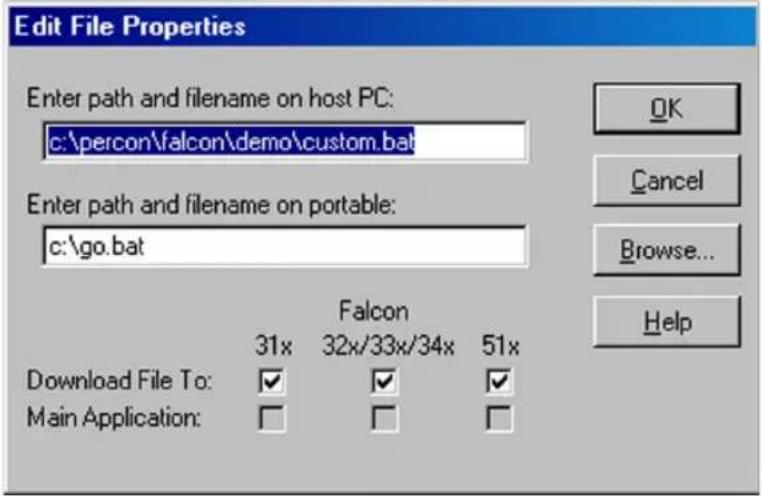
text_image
Edit File Properties Enter path and filename on host PC: c:\percon\falcon\demo\custom.bat Enter path and filename on portable: c:\go.bat Falcon 31x 32x/33x/34x 51x Download File To: ✓ ✓ ✓ Main Application: □ □ □ OK Cancel Browse... HelpDelete To delete a file from the Application Files list, select the file in the list and then select Delete.
Select Product: Select the appropriate radio-button for type the Falcon model being configured: 31x, 32x/33x/34x, or 51x.
Next Select Next to view or change additional file-configuration options for the custom installation.
Done 1. Select Done when finished setting file-configuration options for the custom installation.
- The second File Configuration window (Figure 2-10) appears if Next is selected in the first window.
Figure 2-10: The Second File Configuration Window
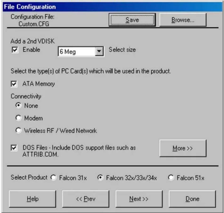
text_image
File Configuration Configuration File: Custom.CFG Save Browse... Add a 2nd VDISK Enable 6 Meg Select size Select the type(s) of PC Card(s) which will be used in the product. ATA Memory Connectivity None Modem Wireless RF / Wired Network DOS Files - Include DOS support files such as ATTRIB.COM. More >> Select Product Falcon 31x Falcon 32x/33x/34x Falcon 51x Help << Prev Next >> DoneConfiguration File This field shows the configuration file used to specify the files that will be loaded into the Falcon.
Save After changing selections in this window, select Save to save the revisions in the current configuration file or in a new one.
Browse 1. Select Browse to use a different configuration file.
- An Open dialog box appears.
- Use the Open dialog box to choose a configuration file from the Configs folder.
- If Browse is selected after making changes in this or any other File Configuration window and the changes are not saved, the prompt shown in Figure 2-5 on page 2-8 appears.
Add a 2nd VDISK: Select to add a 2nd VDISK in the extended memory area on the Falcon. (Refer to page 1-10.)
Select Size: Use this drop down list box to select the size of the 2nd disk.
ATA Memory Cards: Turn this switch on to transfer drivers for ATA memory cards to the Falcon.
I/O Cards: Turn this switch on to transfer drivers for fax/modem cards to the Falcon.
Vendor Specific: Turn this switch on to transfer drivers for other types of PC cards.
This option loads PC Card drivers for Card and Socket Services only. Generic client drivers such as ATA or I/O Card drivers are not loaded if this is the only card switch turned on.
Use this for RF cards that have their own specific client drivers that will be loaded using application files in the first file configuration window. (refer to page 2-9)
DOS Files: Turn this switch on to transfer files for DOS commands and utilities to the Falcon.
More Select More to add or remove DOS files from the custom installation. The Select DOS Files dialog box appears (Figure 2-11 on page 2-14).
Highlight DOS files to download to portable: This field lists DOS files that are available. Files that are highlighted are currently selected to be included in the custom installation. Click on a file to select it or deselect it.
Figure 2-11: The Select DOS Files Dialog Box

text_image
Select DOS Files Highlight DOS files to download to portable : Chkdsk.com Choice.com Deltree.exe Find.com Label.com Mem.exe Mode.com More.com Print.com Share.exe Sort.com Tree.com Xcopy.com Directory on portable to store DOS files : c:\dos Select Product ○ Falcon 31x ● Falcon 32x/33x/34x ○ Falcon 51x Help DoneDirectory on portable to store DOS files: Use this field to specify where the DOS files should be placed in the Falcon unit.
Done Select Done to return to the File Configuration window.
Select Product: Select the appropriate radio-button for type the Falcon model being configured: 31x, 32x/33x/34x, or 51x.
Prev Select Prev to return to the previous file-configuration window.
Next Select Next to move on to the next file-configuration window.
The third File Configuration window (Figure 2-12) appears if Next is selected in the second window.
Done Select Done when finished setting file-configuration options for the custom installation.
Figure 2-12: The Third File Configuration Window
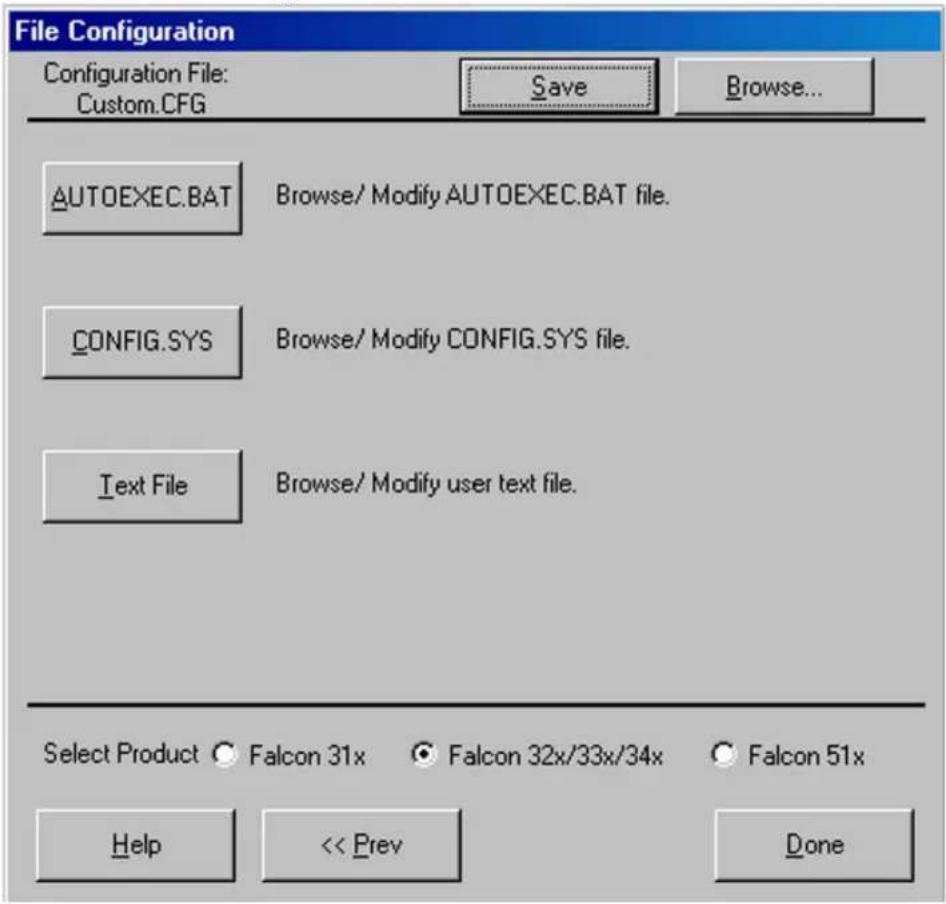
text_image
File Configuration Configuration File: Custom.CFG Save Browse... AUTOEXEC.BAT Browse/ Modify AUTOEXEC.BAT file. CONFIG.SYS Browse/ Modify CONFIG.SYS file. Text File Browse/ Modify user text file. Select Product ○ Falcon 31x ● Falcon 32x/33x/34x ○ Falcon 51x Help << Prev DoneConfiguration File: This field shows the configuration file used to specify the files that will be loaded into the Falcon.
Save After selecting options in this window, select Save to save the revisions in the current configuration file or in a new one.
Browse 1. Select Browse to use a different configuration file.
- An Open dialog box appears.
-
Use the Open dialog box to choose a configuration file from the Configs folder.
-
If Browse is selected after making changes in this or any other File Configuration window and the changes are not saved, the prompt shown in Figure 2-5 on page 2-8 appears.
AUTOEXEC.BAT: Select this option to insert new commands into the autoexec.bat file that will be transferred to the Falcon.
CONFIG.SYS: Select this option to insert new commands into the config.sys file that will be transferred to the Falcon.
Text File: Select this option to view or modify any text file that will be transferred to the Falcon.
Select Product: Select the appropriate radio-button for type the Falcon model being configured: 31x, 32x/33x/34x, or 51x.
Prev Select Prev to return to the previous file-configuration window.
Done Select Done when finished setting file-configuration options for the custom installation.
The Program Settings Windows
- Select the Program Settings from the Custom Configuration Menu and the first of six Program Settings windows appears.
-
Use these windows to view or change settings for bar code symbologies and other programmable options.
-
The first window is shown in Figure 2-13 on page 2-17.
- The next four windows are similar, and so are not shown.
Program Settings File: This field shows the program-settings file that will be loaded into the Falcon.
Save After selecting options in this window, select Save to save the revisions in the current program-settings file or in a new one.
Browse 1. Select Browse to use a different program settings file.
-
The Open dialog box appears.
-
Use the dialog box to choose a configuration file from the Progsets folder.
Figure 2-13: The First Program Settings Window
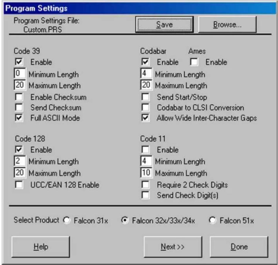
text_image
Program Settings Program Settings File: Custom.PRS Save Browse... Code 39 ✓ Enable 0 Minimum Length 20 Maximum Length □ Enable Checksum □ Send Checksum ✓ Full ASCII Mode Codabar Ames ✓ Enable □ Enable 4 Minimum Length 20 Maximum Length □ Send Start/Stop □ Codabar to CLSI Conversion ✓ Allow Wide Inter-Character Gaps Code 128 ✓ Enable 2 Minimum Length 20 Maximum Length □ UCC/EAN 128 Enable Code 11 □ Enable 4 Minimum Length 10 Maximum Length □ Require 2 Check Digits □ Send Check Digit(s) Select Product ○ Falcon 31x ○ Falcon 32x/33x/34x ○ Falcon 51x Help Next >> Done- If Browse is selected after making changes in this or any other Program Settings window and the changes are not saved, the prompt shown in Figure 2-6 on page 2-8 appears.

On/Off Switches: The smaller white boxes are on/off switches. Click in the box to toggle a switch.

Input Fields: Enter specific settings for parameters in the larger white boxes. (Refer to Appendix C for a table of parameters and settings.)
Select Product: Select the appropriate radio-button for type the Falcon model being configured: 31x, 32x/33x/34x, or 51x.
Prev Select Prev to return to the previous program-settings window.
Next Select Next to move on to the next program-settings window.
Done 1. Select Done when finished making program settings for the custom installation.
- The sixth Program Settings window (Figure 2-14) appears if Next is selected in the fifth window.
Figure 2-14: The Sixth Program Settings Window
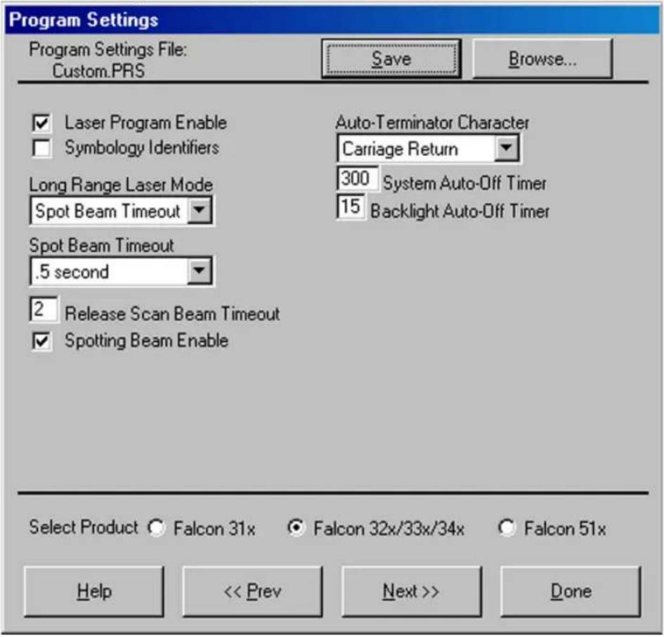
text_image
Program Settings Program Settings File: Custom.PRS Save Browse... ✓ Laser Program Enable ✓ Symbology Identifiers Auto-Terminator Character Carriage Return Long Range Laser Mode Spot Beam Timeout 300 System Auto-Off Timer 15 Backlight Auto-Off Timer Spot Beam Timeout .5 second 2 Release Scan Beam Timeout ✓ Spotting Beam Enable Select Product ○ Falcon 31x ○ Falcon 32x/33x/34x ○ Falcon 51x Help << Prev Next >> DoneProgram Settings File: This field shows the program-settings file that will be loaded into the Falcon.
Save After selecting options in this window, select Save to save the revisions in the current program-settings file or in a new one.
Browse 1. Select Browse to use a different program settings file.
2. The Open dialog box appears.
Figure 2-15: The Last Program Settings Window
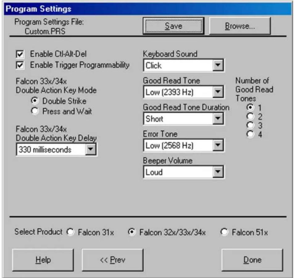
text_image
Program Settings Program Settings File: Custom.PRS Save Browse... Enable Ctrl-Alt-Del Enable Trigger Programmability Keyboard Sound Click Falcon 33x/34x Double Action Key Mode Double Strike Press and Wait Good Read Tone Low (2393 Hz) Number of Good Read Tones 1 2 3 4 Falcon 33x/34x Double Action Key Delay 330 milliseconds Good Read Tone Duration Short Error Tone Low (2568 Hz) Beeper Volume Loud Select Product ○ Falcon 31x ○ Falcon 32x/33x/34x ○ Falcon 51x Help << Prev Done- Use the Open dialog box to choose a configuration file from the Progsets folder.
- If Browse is selected after making changes in this or any other File Configuration window and the changes are not saved, the prompt shown in Figure 2-6 on page 2-8 appears.
Spotting Beam Enable
Spotting Beam Enable: Select to enable the Spotting Beam. This feature is reviewed in the Falcon DOS Portable Data Terminal User's Guide on page 58.
√ Laser Program Enable
On/Off Switches: The smaller white boxes are on/off switches. Click in the box to toggle a switch.
300 System Auto-Off Timer
Input Fields: Enter specific settings for parameters in the larger white boxes. (Refer to page C-3 for a table of parameters and settings.)
Falcon 33x/34x Double Action Key Mode ● Double Strike ○ Press and Wait
Double Action Key Mode: Select Double Strike or Press and Wait as the Double Action Key Mode. Both selections in the Falcon DOS Portable Terminals User's Guide on page 38.
Falcon 33x/34x Double Action Key Delay 330 milliseconds
Double Action Key Delay: Select Double Action Key delay. This feature is reviewed in the Falcon DOS Portable Terminals User's Guide on page 38.
Good Read Tone Low (2393 Hz)
Drop-Down Lists: Click on the list to view the options, and select the desired option.
Number of Good Read Tones 1 2 3 4
Radio Buttons: Select the desired setting by clicking on it.
Prev Select Prev to return to the previous program-settings window.
Done Select Done when finished making program settings for the custom installation.
The Comm Settings Dialog Box
- Select Comm Settings from the main menu or the Custom Configuration menu.
- The Comm Settings dialog box (Figure 2-16 on page 2-21) appears.
- Use this dialog box to view or change settings for serial communications with the Falcon.
Figure 2-16: The Comm Settings Dialog Box
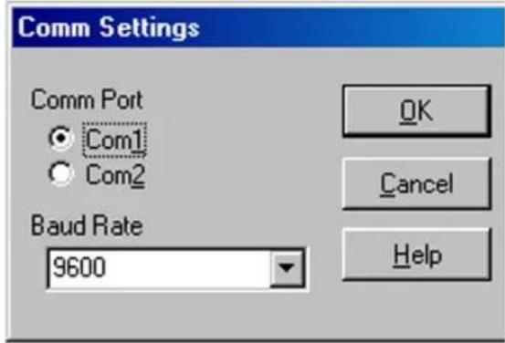
text_image
Comm Settings Comm Port Com1 Com2 Baud Rate 9600 OK Cancel HelpComm Port: Select the desired serial port for the PC to communicate with the Falcon. The default port is COM1.
Baud Rate: Select the baud rate for serial communications between the PC and the Falcon. The default is 9600.
The File Transfer Window
-
When selecting Transfer Files from the main menu, the File Transfer window appears (Figure 2-18 on page 2-22).
-
Use this window to select data files for transfer between the Falcon and the computer.
List File: This field shows the name of the file-list file, when selected.

Transfer files can be selected without using or creating a list file.
Save After making changes in the Files to Transfer list, select Save to save the revisions in the current file-list file (if any), in another existing file, or in a new file.
Browse 1. Select Browse to use a different file-list file.
- An Open dialog box appears.
Figure 2-17: The File Transfer Window
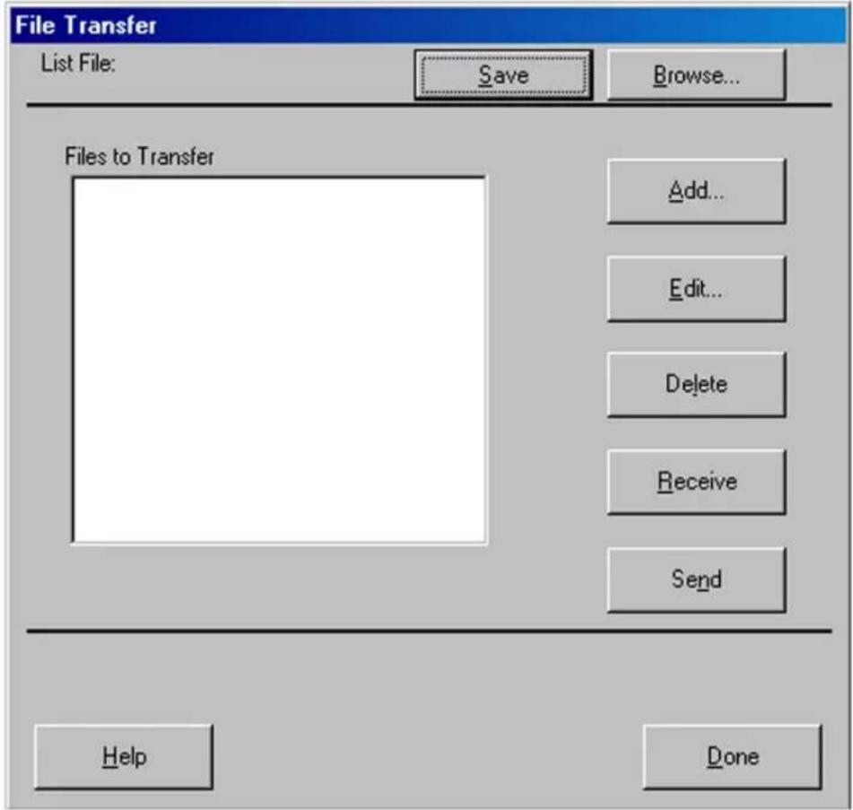
text_image
File Transfer List File: Save Browse... Files to Transfer Add... Edit... Delete Receive Send Help Done- Use the dialog box to choose a configuration file from the Filelist folder.
- If Browse is selected after making changes in this or any other File Transfer window and the changes are not saved, the following prompt appears:
Figure 2-18: The Prompt for Saving Changes to the Current File List

text_image
Save File List Do you wish to save this file list? Yes No CancelYes1. Select this option to save the changes.
-
A Save As dialog box will open.
-
Use the dialog box to specify the location and name of the new file-list file.
No Select this option to discard the changes.
Cancel Select this option to return to the File Transfer window without saving or discarding the changes.
Files to Transfer: This field shows the files that will be included in the transfer between the Falcon and the PC.
Add Select Add to include additional data files in the transfer. The File Selection dialog box open (Figure 2-19 on page 2-23.)
Figure 2-19: The File Selection Dialog Box for Adding a Data File
text_image
File Selection Enter path and filename on host PC: c:\percon\falcon\demo\pal2.bat Enter path and filename on portable: c:\pal2.bat OK Cancel Browse... HelpEnter path and filename on host PC: Use this field to specify the location of the file on the PC.
Enter path and filename on portable: Use this field to specify the location and name for the transferred file on the Falcon.
OK Select OK to return to the File Transfer window. The specified data file will appear in the Files to Transfer list.
Cancel Select Cancel to return to the File Transfer window without adding a file to the Files to Transfer list.
Browse 1. Select Browse to view the files on the computer.
-
The Open dialog box appears.
-
Use the dialog box to choose a data file to be included in the transfer.
Edit 1. Select a file in the file list and then select Edit to change the source path or destination path for the file.
2. The Edit File Properties dialog box opens (Figure 2-20).
Figure 2-20: The Edit File Properties Dialog Box

text_image
Edit File Properties Enter path and filename on host PC: c:\percon\falcon\demo\pal2.bat Enter path and filename on portable: c:\pal2.bat OK Cancel Browse... Help- The fields and buttons in this dialog box are the same as in the File Selection dialog box above.
Delete To delete a file from the list, select the file and then select Delete.
Receive Select Receive to begin a file transfer from the Falcon to the PC
- When selected, the configuration utility prepares files to be transferred to the PC and opens the Important dialog box (Figure 2-2 on page 2-5).
- Make certain the Falcon unit is properly connected to the serial port specified in the Comm Settings dialog box (refer to page 2-20).
- Then run the ld.bat file on the Falcon, and select OK in the Important dialog box on the computer.
4.
Send Select Send to begin a file transfer from the PC to the Falcon.
- The configuration utility prepares files to be transferred to the Falcon and opens the Important dialog box (refer to Figure 2-2 on page 2-5).
- Make certain the Falcon unit is properly connected to the serial port specified in the Comm Settings dialog box (refer to page 2-20).
- Then run the ld.bat file on the Falcon, and select OK in the Important dialog box.
Done Select Done when finished selecting and transferring files.
3
Using File Transfer Programs
CHAPTER CONTENTS
Using XFER32 3-2
XFER32 Setup....3-2
General Tab 3-3
Transfer Tab....3-5
Logging Tab....3-7
Host Mode....3-8
Sending and Receiving Data 3-8
Send File (to Portable) 3-9
Receive File (from Portable)....3-9
Using XFER 3-10
Syntax and Parameters ....3-11
The XFER_ARGS Environment Variable .....3-26
Multiple-Option Blocks....3-27
The Modem-Initialization File....3-29
Performance....3-32
Error Codes 3-34
XFER32Using XFER32
When you start XFER32, the XFER32 interface, opens ().
Figure 3-1: . XFER32 User Interface
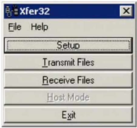
text_image
Xfer32 File Help Setup Transmit Files Receive Files Host Mode ExitXFER32XFER32 Setup
To prepare for data transfer between the PC and the PT40, click on the Setup button to open the Setup dialog box, which contains three tabbed sections. The settings in these dialogs can be modified or customized to meet your communications requirements.
General Tab
Figure 3-2: File Transfer Setup Definition Form: General Tab
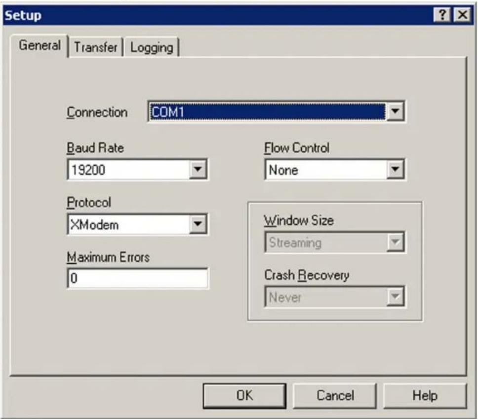
text_image
Setup General Transfer Logging Connection COM1 Baud Rate 19200 Flow Control None Protocol XModem Window Size Streaming Maximum Errors 0 Crash Recovery Never OK Cancel HelpConnection
Enter the Connection port for file transfers. Select from the list of detected serial ports or modems.

text_image
Connection COM1 COM1 COM2Baud Rate
Select a Baud Rate for serial communications from the pull-down list. The default value is 19200.

text_image
Baud Rate 19200 9600 19200 38400 57600 115200Protocol
Select the file transfer Protocol to use for sending and receiving files. The Protocol depends upon what the Host system requires. The default value is ZModem.
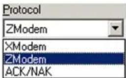
text_image
Protocol ZModem XModem ZModem ACK/NAKRefer to
XModem XModem does not allow multiple file transfers.
ZModem ZModem allows multiple file transfers.
ACK/NAK ACK/NAK does not allow multiple file transfers. Do not use ACK/NAK with PSC Falcon DOS units.
Maximum Errors Enter the maximum number of Errors permitted before a file transfer is aborted. Range: 1 to 50. 0 specifies no limit to the number of file transfer errors.
Flow Control Select the mechanism used to control the flow of data. Sender and receiver must agree on the flow control method.
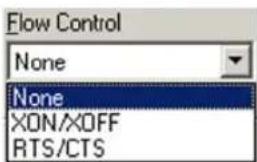
text_image
Flow Control None None XON/XXOFF RTS/CTSNone No flow control used.
XON/XOFF Software flow control using XON and XOFF characters to communicate when to suspend and resume data transfer. Only available with Z-Modem protocol.
RTS/CTS Hardware flow control that uses Ready to Send (RTS), and Clear to Send (CTS) serial port lines to communicate when to suspend and resume data transfer.
Window Size Specifies the amount of data transmitted before receiving a response from the receiver.

text_image
Window Size Streaming Streaming 1024 2048 4096Streaming Sender does not wait for a response before sending all the data.
1024-4096 Causes the sender to wait for a response after sending the specified amount of data.
Crash Recovery Specifies whether or not an attempt is made to complete a file transfer at the point of failure.

text_image
Crash Recovery Never Never Follow sender AlwaysNever Never attempts to recover from a file transfer.
Follow Follows the sender's Crash Recovery and Overwrite options. Sender
Always Forces an attempt to recover from a file transfer.
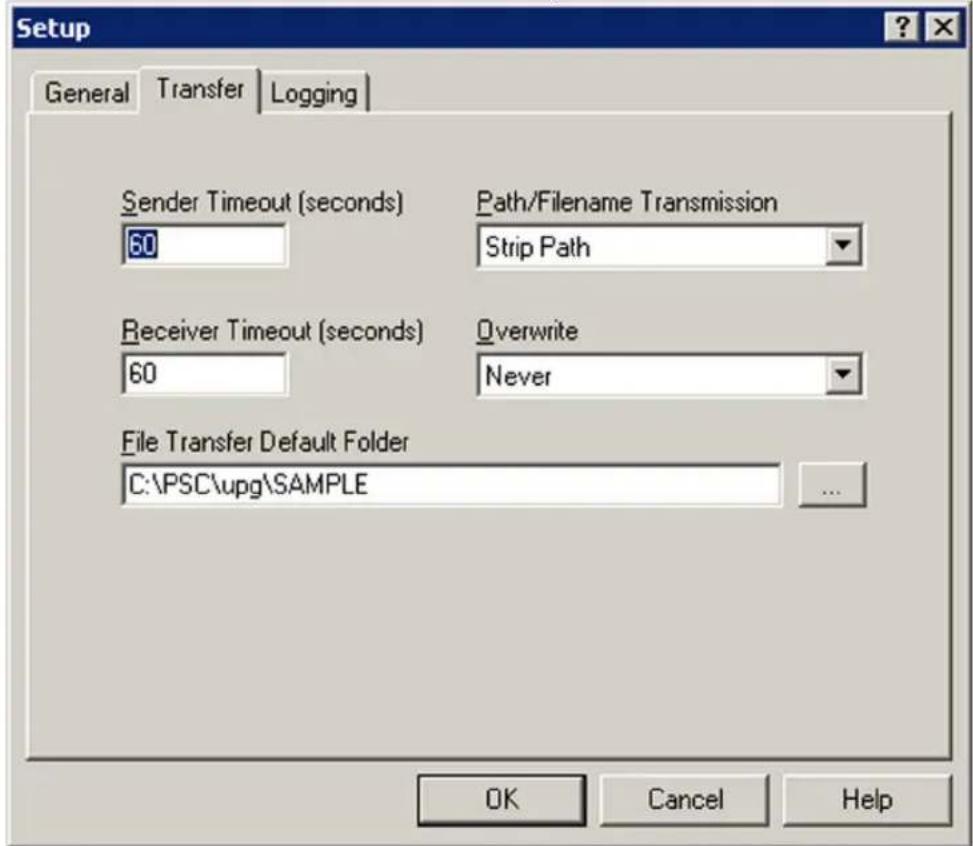
Transfer Tab
This tab establishes file transfer settings. Select the Transfer tab.
Figure 3-3: Transfer Tab of the File Transfer Utility
text_image
Setup General Transfer Logging Sender Timeout (seconds) Path/Filename Transmission 60 Strip Path Receiver Timeout (seconds) Overwrite 60 Never File Transfer Default Folder C:\PSC\upg\SAMPLE OK Cancel HelpSender Timeout (Seconds) Enter the maximum number of seconds to wait for a connection when sending files. A value of 0 waits indefinitely.
Receiver Timeout Enter the maximum number of seconds to wait for a connection when receiving files. A value of 0 waits indefinitely.
Path/Filename Enter a Path/Filename Transmission to control how the sender Transmission processes the paths and filenames of files to be sent. Only applies to Z-Modem.
Strip Path Sends only the filename (no path) to the receiver.
Send Path Sends the filename with path to the receiver.
Specify Allows both the filename and path for each file to be altered prior
Receiver's File to being sent to the receiver.
Path/Name
Overwrite Select to determine the action the receiver takes when a received file already exists.
Source Longer or Overwrites the existing file if the received file is longer or newer. Newer
CRCs Don't Overwrites the existing file if the CRCs of both files don't match. Match
Append Appends the received file to the existing one.
Always Overwrites the existing file with the one received.
Source Newer Overwrites the existing file if the received file is newer.
Date/Length Overwrites the existing file if the dates or lengths of both files don't match. Don't Match match.
Never Skips the transfer if the received file already exists.
File Transfer Default Enter the File Transfer Default folder for storing received files. Use the Browse button to locate a new location.

text_image
File Transfer Default Folder C:\PDTFilesLogging Tab
This tab establishes settings for the communications log. Click the Logging tab.
Figure 3-4: Logging Tab of the File Transfer Utility

text_image
Setup General Transfer Logging ✓ Log To File ✓ Append To Log ✓ Log to Screen Log Path/Filename C:\PDTFiles\winxfer.log OK Cancel HelpLog To File Specifies that the log is to be written to a text file.
Log To Screen Specifies that the log is displayed on screen.
Append to Log This option becomes available when you select Log to File. When enabled, Append to Log adds log information to the end of the log file. If not enabled, new log information replaces the previous log file.
Log Path/ Specify the location for storing the communications log.
Filename If a path is not given, the file is stored in the Default File Transfer folder.
Browse Use the Browse button to locate a new log file.
Host Mode
Host Mode is a method of receiving files using the Z-Modem protocol. It continuously waits for files and receives them using the filenames specified by the sender. Once files have been received, it goes back to waiting for additional files. Select Transfer Files > Host Mode from the menubar.
Figure 3-5: Host Mode Window
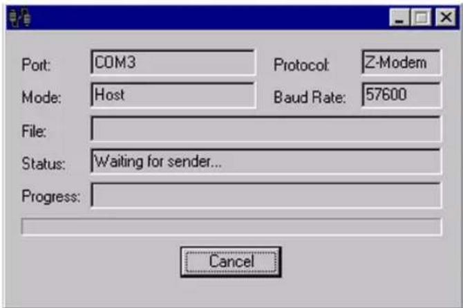
text_image
Port: COM3 Protocol: Z-Modem Mode: Host Baud Rate: 57600 File: Status: Waiting for sender... Progress: CancelSending and Receiving Data

UPG uses the File Transfer Manager to transfer data (collection, validation, and INI files) between a portable data collection unit and the host PC. It is possible to send and receive files with the File Transfer Manager without switching between utilities. Send and receive files only works with direct connections between a host PC and portable data collection unit. To receive data from a portable via modem, use a communications utility that supports a modem (XFER32 or UPG Runtime or commercially available communications programs). Use the same protocol as selected in the Communication Settings window to receive a file via modem using the external communications package; see the documentation for the communication package for more information.
Verify that the portable is properly attached to the host PC. If the portable uses a dock, make sure that the dock is properly attached to the PC. Many docks require the use of a null-modem with a serial cable and power supply. Check the portable/dock documentation for more information.
Send File (to Portable)
- Select Transfer Files > Send File from the menubar.
Figure 3-6: Send File to Portable Window

text_image
Select File to Transfer Look jn: test temp.txt History Desktop My Documents My Computer My Network P... File name: temp.txt Files of type: Text Files Open Cancel- Select the file(s) to send.
- You can select multiple files if you are using the ZModem protocol.
- Click Open to send the file to the data collection terminal
- Press Cancel to not send any files
If the Path/Filename Transmission is set to Specify Receiver's File/Pathname, the file names may be altered prior to being sent to the receiver. A Send File As... dialog is displayed to permit the changing of the path/name of each file. The dialog contains a list of each file to be sent. The left column displays the path/name of each file as it exists on this computer. The right column displays the same file as seen by the receiver. To change the path/name assigned to a file, select the filename to change, and then click Edit. Or, double-click the filename from the list.

Receive File (from Portable)
When receiving files from a data collection terminal, a prompt appears. Enter the name of the incoming file.
- Select Transfer Files >Receive from the menubar.
Receive File from Portable Window
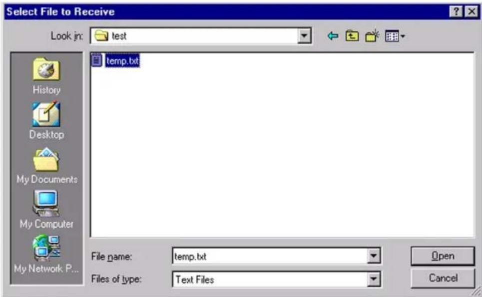
text_image
Select File to Receive Look in: test temp.txt History Desktop My Documents My Computer My Network P... File name: temp.txt Files of type: Text Files Open Cancel-
Select (or enter) a filename for the file.
-
You can select multiple files if you are using the ZModem protocol.
- Filenames are assigned to files in the order listed in the File Name field.
-
You can also use the filename(s) supplied by the sender. Press Cancel to select this option.
-
Click Open to begin receiving the file.
- Press Cancel to not receive any files.
Using XFER
XFER (xfer.exe) is a DOS utility that directs the serial transfer of ASCII and binary data between two computers. This chapter provides information for advanced users and system administrators who want to use XFER to transfer files between a Falcon and a PC. For basic information about XFER, refer to page 1-11.

XFER runs on Falcon portables using DOS. Use XFER32XFER32 on the Host PC with Win32. Use the native on-help with XFER32.
When using Z-modem, flow control must be the same on both sides of the transmission. Normally, XFER defaults to RTS/CTS flow control. On the Falcon 33x and 34x, it defaults to Xon/Xoff. When transferring files between a 33x or 34x and the host PC, make sure the PC is also using Xon/Xoff. See the /F option on page 3-18 for more details.
XFER supports Xmodem and Zmodem transfers at speeds up to 115200 baud. Modem support is provided via an initialization file that specifies option settings for the modem. Option settings can be specified on the command line or with an environment variable called XFER_ARGS.
XFER supports RTS/CTS handshaking for Xmodem protocol and both XON/XOFF and RTS/CTS handshaking for Zmodem protocol.
Syntax and Parameters
The command line syntax for XFER is as follows:
XFER [/option1 [/option2] . . . ] filename(s)
Use a slash (/) or a hyphen (−) to denote options, and use uppercase or lowercase letters for them. Options can be placed before or after filenames on the command line.
Basic options and their defaults are listed and described in Table 3-1. The Default column indicates whether the option is used (On) or ignored (Off) if it is not included in the command line. For options that have two or more possible values, the default value is given.
A page number for each option indicates where a full explanation can be located in this manual.
Table 3-1: XFER Parameters
| Option Description | Default | ||
| Xmodem | Zmodem | ||
| filename(s)(page 3-14) | Identifies the file to be transferred or received. | None None | |
| @file(page 3-15) | (Zmodem only) Specifies a response file consisting of two or more names of files to be transferred. Replace file with the name of the response file to use. | N/A None | |
| #(page 3-16) | Specifies the communications port to use. Replace the # symbol with the desired setting: 1 = COM1 2 = COM2 | 1 | 1 |
| B#(page 3-16) | Specifies the baud rate. Replace the # symbol with the desired setting: 2400 4800 9600 19200 38400 57600 115200 | 19200 19200 | |
| C#(page 3-16) | (Zmodem only) Specifies how the retransmission of a file should be handled if a previous transfer was interrupted. Replace the # symbol with the desired setting:1 = Never recover (start transmission from the beginning of the file)2 = Follow sender (use the sender's crash-recovery options; ignore the receiver's)3 = Always recover (send data from the point where transmission was interrupted) | N/A 1 | |
| D#(page 3-17) | Specifies the number of seconds for XFER to wait for activity before cancelling the transfer. Replace the # symbol with the desired number of seconds for the timeout delay. Acceptable values are 0(no timeout) through 65,535. | 60 60 | |
| E#(page 3-18) | Specifies the maximum number of times XFER should attempt retransmission of a packet after an error occurs. If the final attempt fails, XFER aborts the transfer. Replace the # symbol with the desired maximum number of attempts. A setting of 0 allows for unlimited attempts. | 0 | 0 |
| F#(page 3-18) | Specifies the type of flow control to use for data transfer. Replace the # symbol with the desired setting:0 = No flow control1 = XON/ XOFF (Zmodem only)2 = RTS/ CTS | 0 | 1 = Falcon 33x or 34x2 = all other Falcon models |
| H or ?(page 3-19) | Displays help for the XFER command. | None None | |
| Ifile(page 3-19) | Specifies the modem-initialization file. Replace file with the name of the file to use. | modem.ini | modem.ini |
| Mcommand(page 3-19) | Sends a command to the modem before beginning the data transfer.Replace command with one of the following:A = Auto answerATstr = Send ATstr commandsD#x = Dial memory #x (0-9)Dstr = Dial phone number str | None None | |
| N(page 3-20) | Forces XFER to ignore all previously specified option settings, including filenames and options specified in the XFER_ARGS environment variable. All XFER options are set to their default state. | Off Off | |
| O#(page 3-20) | Overwrites an existing file with a new file having the same name.Replace the # symbol with the desired setting:1 = Overwrite if source is longer or newer (Zmodem only)2 = Overwrite if CRCs don't match (Zmodem only)3 = Append to existing file (Zmodem only)4 = Always overwrite5 = Overwrite if source is newer (Zmodem only)6 = Overwrite if dates or lengths don't match (Zmodem only)7 = Never overwrite | 7 | 7 |
| Q(page 3-22) | Toggles quiet mode on and off. In quiet mode, only the filename and a "Transmitting..." or "Receiving..." message is displayed. When quiet mode is off, additional information is displayed. Each use of this option reverses the quiet-mode state. | Off Off | |
| R(page 3-22) | Receives the specified file or files. | Off | On if no file is specified |
| S#(page 3-23) | (Zmodem only) Specifies how paths and names should be handled when sending files. Replace the # symbol with the desired setting:0 = Strip paths1 = Send paths2 = Send new paths/filenames | N/A 0 | |
| T(page 3-24) | Transmits the specified file or files. | On | On if file is specified |
| W# (page 3-25) | Window size (Zmodem only): x = Packet size, in bytes0 = Streaming | N/A 0 | |
| X (page 3-26) | Uses Xmodem protocol for the transfer. | ||
| Z (page 3-26) | Uses Zmodem protocol for the transfer. | ||
filename(s) Name(s) of the File(s) to Send or Receive:
Xmodem
Only one file can be transferred at a time. The entire path can be specified, including the drive letter. If the path is not specified, the file is sent from or received into the current directory. If the directory or file doesn't exist on a send, or the directory doesn't exist on a receive, the transfer will fail, with a file-open error.
The filename must be included on the command line when receiving a file. If multiple files are specified for Xmodem, only the first file will be transferred. All other file names will be ignored.
Zmodem
Zmodem allows up to 256 files to be transferred in one session. The entire path for each file can be specified, including the drive letter. If a path is not specified, the file is sent from or received into the current directory. If the directory or the file doesn't exist on a send, or the directory doesn't exist on a receive, the transfer will fail, with a file-open error. DOS accepts only 128 characters on the command line, but a response file can be used to get around this limitation. (Refer to the @file option on page 3-15.)
When receiving, the filename does not need to be specified for Zmodem. Zmodem transfers the name of the file to be sent before sending the file. (See the S option on page 3-23 for information on controlling how Zmodem sends the filename.) Any filename specified on the receiving end will override the default name that is sent by the sender.
When multiple files are sent, a one-to-one correspondence is established. For example, if ten filenames are specified on the sender's side and five filenames are specified on the receiver's side, the first five files transferred will be received with the names specified on the receiver's command line, while the last five files
will be received with the names specified on the sender's command line (assuming all the files exist). Each filename on the command line can include its own path.
XFER also recognizes the wildcard characters ? and *. Normal DOS pattern-matching rules for these characters apply. Be careful about using wildcards when receiving: XFER expands the wildcards of the specified filenames and then searches for any matching patterns in the specified directory. If no matching files are found (in an empty directory, for instance), then no filenames will be sent to the Zmodem receive procedures. This may or may not be what was intended. Also, DOS does not store files in alphabetical order, and so using *.* to both send and receive files may result in files being renamed because they are loaded in a different order. This can occur even if the file lists on both sides of the transfer are the same.
@file
Response File (Zmodem only): The @file option allows use of a “response file” for specifying filenames when conducting Zmodem transfers. This option allows circumvention of the DOS limitation of 128 characters on the command line when sending many files in a single transfer session.
When using a response file, fill the file with the filenames to be sent or received. The filenames may include drives and paths. One filename should appear on each line of the response file. Up to 256 files can be specified in this way.
The following is a sample response file, named response.txt:
autoexec.bat
c:\programs\theprog.exe
c:\data\file1.dat
c:\data\file2.dat
c:\data\file3.dat
Not all the filenames need to be specified in the response file. For example, the following command would send seven files, including the five in response.txt above.
xfer /z c:\default\config.sys /@response.txt c:\data\file4.dat
In this case, each filename is read in as it appears on the command line. The file c:\default\config.sys would be the first one sent, the autoexec.bat file specified in the response.txt file would be the second file sent, and the c:\data\file4.dat file specified on the command line would be the seventh file sent.
Multiple response files can be specified. Regardless of the number of response files used, the 256-file limitation for a single transfer session is always in effect.
If a response file is included in the XFER_ARGS environment variable (refer to page 3-26), the N option can be used to ignore the response file and start from a default condition (refer to page 3-20).
Response files can be used with the S2 option (refer to page 3-23). In this case, the format for the response file would be:
autoexec.bat c:\autoexec.bat
c:\programs\theprog.exe c:\prog.exe
c:\data\file1.dat d:\data1
c:\data\file2.dat d:\data2
c:\data\file3.dat d:\data3
In this case, the first filename on a line specifies the file on the sender's side. The second filename on the line specifies the filename the sender will pass to the receiver.

The receiver's filename is separated from the sender's filename by a single space. If more than one space is used, the additional spaces will be included as part of the receiver's filename. Because a space character is used as a delimiter, Windows 95 and Windows NT filenames with spaces as part of the filename will not be parsed correctly and should not be used. Placing quotes around the filename will not help in this situation.
The @file option can be used only in Zmodem transfers. The Z option must be specified before the @file option. If a response file is used with the S2 option, the S2 option must be specified before the @file option.
All other rules governing filenames apply to response files.
# COM Port: This option specifies the communications port to use for the file transfer. Replace the # symbol with the desired setting:
$$ 1 = \text { COM1 } \quad 2 = \text { COM2 } $$
B# Baud Rate: This option specifies the baud rate to be used for the file transfer. Replace the # symbol with the desired setting:
$$ \begin{array}{l l l l l l l} 2 4 0 0 & 4 8 0 0 & 9 6 0 0 & 1 9 2 0 0 & 3 8 4 0 0 & 5 7 6 0 0 & 1 1 5 2 0 0 \end{array} $$
C# Crash Recovery (Zmodem only): Crash recovery refers to the ability of Zmodem protocol to detect that a file transfer was not completed and to attempt to recover at the point of failure (instead of recopying the entire file). For instance, if the communications link is severed during the transfer of a 10K file, with only 5K of data successfully transferred, crash recovery can be used to send the remaining 5K without resending the entire 10K file.

This option is supported by Zmodem protocol only. Xmodem will never attempt to recover a file after a crash.
Crash recovery uses the CRC of the sender's and receiver's files to ensure that the portion of the file that was successfully received in the first transfer is identical to that portion of the sender's copy of the file. If this is true, then the receiver instructs the sender to begin sending data beginning at the point in the file that corresponds to the end of the file on the receiver's side.
By default, crash recovery is turned off. To use the C option, replace the # symbol with the desired setting:
1 - No crash recovery
2 - Follow sender
3 - Always use crash recovery
If the C option is used without including a number, then the 1 setting is assumed. An invalid setting will result in an error on the command line.
The C option can be used in conjunction with the O option. If C2 (follow sender) is specified on the command line, the receiver will use the sender's crash and overwrite options. Any overwrite options local to the receiver will be ignored. This is useful if a default crash-recovery command is specified in the XFER_ARGS environment variable (refer to page 3-26) and crash recovery for the current transfer is temporarily disabled.
D# Delay Before Terminating Transmission: This option allows specifying a timeout. If the specified number of seconds elapse with no characters received by either the sender or the receiver, the program aborts the transfer session.

This option is supported by Zmodem protocol only. Xmodem will never attempt to recover a file after a crash.
To use the D option, replace the # symbol with the desired number of seconds for the timeout delay. Acceptable values are 0 (no timeout) through 65, 535; the default is 60. A value of 0 disables the timeout feature, meaning that the transfer session will never be aborted because of inactivity. If the D option is used without specifying a number, an error will occur.
E# Maximum Number of Errors Before Aborting Transfer: The E option is used to specify the maximum number of times the receiver will request a retransmission of a packet before aborting the transfer session.

For multiple file transfers in Zmodem, the entire session is aborted, not just the transfer of the current file.
The default is 0, meaning the transfer will never be aborted because of errors. If the E option is used without specifying a number, an error will occur.
F# Flow Control: This option is used to specify what type of flow control to use for the file transfer.
Flow control is the ability of the receiver to detect that data is coming in faster than it can receive and to issue a command to the sender instructing it to stop sending data. When the receiver is again able to handle new data, it issues another command instructing the sender to resume the transfer of data.
XFER supports two types of flow control: software (XON/XOFF) and hardware (RTS/CTS). Only one type can be used at a time. The sender and receiver should have this option enabled similarly.
To use the F option, replace the # symbol with the desired setting:
0 - No flow control
1 - XON/ XOFF (Zmodem only)
2 - RTS/ CTS
If the F option is used without specifying a number, it is assumed to mean F0, or no flow control. This is useful in the case where flow control is specified in the XFER_ARGS environment variable (refer to page 3-26) but flow control is turned off for the current transfer session. An invalid setting will result in an error on the command line.

The RTS/CTS flow control option is only available when using XFER with the Falcon 31x and 32x.
Flow control defaults and capabilities differ depending upon the protocol (Xmodem or Zmodem) being used.
Xmodem: If the F option is not included in the command line, no flow control is used. XON/XOFF cannot be used with Xmodem protocol, because Xmodem protocol sends raw binary data and cannot distinguish between the XON/XOFF characters and file data. Attempting to specify XON/XOFF with Xmodem protocol will result in an error.
Zmodem: On the Falcon 33x and 34x, the default flow control for Zmodem is Xon/Xoff. For all other portables and host PCs, the default is RTS/CTS. On a Falcon portable, flow control should be used when transferring with Zmodem, especially if Zmodem is in streaming mode. In streaming mode, the Zmodem sender does not wait for acknowledgements to packets but continuously sends a stream of data. Often this can overwhelm the receiver especially if it is receiving at high data rates or receiving to the C drive or to a PCMCIA ATA card, which writes data to disk much slower than the D drive.
H or ? Help: This option displays a brief description of the XFER syntax, options, and settings.
Ifile Modem-Initialization File: This option specifies the file that contains modem setup and control commands. Refer to The Modem-Initialization File on page 3-29 for complete information about Ifile.
Mcommand Modem Command: This option allows commands to be sent to the modem before the start of the file transfer. To use the M option, replace command with one of the following commands:
A = Auto answer
ATstr = Send ATstr commands
D#x = Dial memory #x (0-9)
Dstr = Dial phone number str
Specifying XFER /MA instructs the modem to go into auto-answer mode. In this mode the modem will wait for the timeout period specified in the modem-initialization file for another modem to dial into it. On detection of a ring-in signal, XFER will answer the line and attempt to start a file transfer.
Specifying XFER /MATstr allows a string of AT commands to be sent to the modem. These commands will be sent to the modem after the initialization string from the modem-initialization file and can be used to specify a different configuration. Since only one modem command can be specified on the
command line, any commands to auto-answer or dial must be included in the AT string.
There are two methods for dialing numbers. The first method uses the format XFER /MD#x, where x is a number from 0 through 9. This number corresponds to a directory number from the modem-initialization file, which identifies a number that should be dialed for this transfer (see the NUMBER# keyword on page 3-31). If a number is not specified, directory number 0 is used.
The second dialing method is to use the XFER /MDstr format, where str is a dialing command to be sent directly to the modem. This string can be any recognizable phone number text, such as (555) 444-3333 or 5554443333.
The last M option on the command line or in the environment variable is the one used for controlling the modem. All earlier modem-command settings are ignored.
If the M option is used without specifying a command, the modem will be disabled for that transfer session. This is useful in the case where modem commands are specified in the XFER_ARGS environment variable (refer to page 3-26) but are transferring files without a modem for the current transfer session.
N Ignore Previous Option Settings: This option causes XFER to ignore previously specified options and return to a default state. All options specified in the XFER_ARGS parameter and on the command line preceding the N are ignored. All options that XFER supports are returned to the default state, and all filenames, response files, modem-initialization files, and modem commands that are specified before the N (including the XFER_ARGS environment variable) are discarded.
The N option is useful when the XFER_ARGS environment variable is used to redefine defaults for XFER. It isn't always obvious that the XFER_ARGS parameter is controlling the behavior of XFER, and it is often the case that several parameters have been redefined. Instead of having to set each option back to its default, use the N option to return XFER to a known state.
O# Overwrite Existing File(s): The O option specifies what action the receiver should take if the file being transferred already exists on the receiver's side. When using this option, replace the # symbol with the desired setting:
1 - Overwrite if source is longer or newer
2 - Overwrite if CRCs don't match
3 - Append to existing file
4 - Always overwrite
5 - Overwrite if source is newer
6 - Overwrite if dates or lengths don't match
7 - Never overwrite
By default, XFER operates in 07 mode—existing files are never overwritten. For Xmodem, the only valid options are 04 and 07; all other settings resolve to 07 (never overwrite). All settings for the 0 option are available with Zmodem protocol.
To remain compatible with previous versions of XFER, the 0 option used without a setting resolves to the 04 setting (always overwrite). This differs from most other XFER options, where specifying the option without a setting usually resolves to the default condition for that option. To use the default condition for the 0 option, specify the 07 setting.
An invalid setting will result in an error on the command line.

XFER does not prompt to specify whether a file should be overwritten in the default mode. If no overwrite option is specified, the file will never be overwritten. Under Xmodem, the session will abort. Under Zmodem, the file will be skipped and the next file will be transferred.
For the 06 setting under Zmodem, XFER does not set the date or time of a received file to match the original date or time of the sender's version of the file. Instead, the date and time are taken from the receiver's operating system when the file is received and created. Because of this, it is highly unlikely that a file transferred with XFER will have the exact date of the original file. Since the resolution of times for files under DOS is in two-second increments, it is unlikely the timestamps will be the same, even if the times on the receiver and sender are calibrated frequently. Also, DOS doesn't report the seconds field when displaying the modification time of a file during a file listing. So, two files may appear to have the same timestamp when in fact they don't. The tendency with the 06 option is for files to be overwritten, because times usually do not match exactly.
The 03 setting is unique in that it causes the transferred file (binary or ASCII) to be appended to the end of the old file rather than overwriting it.
With Zmodem, the O option can be used with the C option setting for crash recovery (refer to page 3-16). If C2 (follow sender) is specified on the command line, then the receiver will use the sender's crash and overwrite options. Any options local to the receiver will be ignored.
Q Quiet Mode: This option toggles quiet mode. When quiet mode is enabled, minimal information is displayed about the file transfer in progress. Generally, only the name of the file being transmitted is displayed. When not in quiet mode, XFER will display a copyright message, the filename, and file statistics, including a running count of bytes transferred.
Running XFER in quiet mode on the Falcon can significantly improve serial-transfer performance, especially at high speeds. At 115200 baud, transfers are four times faster if quiet mode is enabled on the Falcon than if it is disabled, owing to the delay inherent to writing a running byte count to the screen.
Since the Q option is a toggle switch, each occurrence of it in the command line inverts the quiet-mode state. By default, XFER has quiet mode off. The first occurrence of the Q option turns quiet mode on, the next turns it back off, and so on. This is most useful if the option is specified in the XFER_ARGS environment variable (refer to page 3-26) to activate quiet mode by default but in the current transfer session quiet mode will be deactivated.
R Receive File(s): This option specifies that files are to be received. With Xmodem protocol, the option must be specified whenever receiving a file. The option can be included in the XFER_ARGS environment variable (refer to page 3-26), forcing Xmodem protocol to default to receiving instead of sending files.
With Zmodem, receive is the default if no file is specified on the command line (for example, XFER /z). The name of the file is sent by the transmitting side before the file is transferred, and the file is received with that path and name. To receive a file under Zmodem with a different name from the sender's, use the R option to force Zmodem into receive mode. Specify the new filename after the R option on the receiver's command line (See the filename(s) option on page 3-14 for information on specifying file-names.) When Zmodem has been specified, using the R option without a filename is the same as not using the option at all—the sender's filename (and path) is used.

The last transfer option, R or T, on the command line controls whether to transmit or receive for the session.
S Specify Sender's Path-and-File Handling (Zmodem only): The S option controls how the sender handles the paths and filenames of the files that it sends. This option is available only with Zmodem protocol. The Z option must be specified before using the S option. Use one of the following settings described individually below:
0 - Strip paths
1 - Send paths
2 - Send new paths/filenames
If the S option is not included in the command line, the default setting (0) is used. If the S option is used without specifying a setting (for example, XFER / S), it is assumed to mean S0. This is useful in the case where another option is specified in the XFER_ARGS environment variable (refer to page 3-26) but during the current transfer session, the paths will be stripped.
An invalid setting will result in an error on the command line.
0 Strip Paths: In this mode (the default), the sender will remove any paths that are specified with a filename before sending the filename to the receiver. The new filename will be transmitted to the receiver without any path information. The file will be stored by the receiver in the current directory.
1 Send Paths: This option performs no processing on the filenames specified on the sender's side. Any drive and path information that is specified is transmitted to the receiver. If a path is specified and it does not exist on the receiver's side, the transfer will abort with a failure.
2 Send New Paths/Filenames: When the S2 setting is used, all filenames are treated as filename pairs. This provides the ability to specify dual filenames during a transfer. The first filename (optionally including a drive and path) is the one that the sender uses to open the file. The second filename is used by the sender when it transmits the filename to the receiver. This provides the ability to transfer a file and have it renamed on the receiver's side. It also allows
transfer of a file from one directory on the sender's side to another directory on the receiver's side.
Multiple filename pairs may be specified, which may be separated by other XFER options.
The following conventions must be observed when using the S2 option. Failure to conform may result in errors.
- The S2 command must be specified ahead of any filenames.
- When specifying dual filenames, the filenames must be separated by a single space. The first filename in the pair is what the sender uses, and the second filename is what the sender will transmit to the receiver. If more than one space is used, all spaces after the first will be included as part of the receiver's filename.
- The drive and path may be specified for components for either filename in a pair. The actual name of the file must be included in both filenames along with the drive and the path.
Correct examples:
C:\> xfer /zs2 file1 file2
C:\> xfer /zs2 c:\data\file1 d:\file2
C:\> xfer /zs2 c:\data\file1 d:\file1 c:\yourfile myfile
C:\> xfer /zs2 file1 data1 /b115200 file2 data2
Incorrect examples:
C:\> xfer /zs2 file1 /b115200 file2
C:\> xfer /zs2 file1 file2
C:\> xfer /zs2 file1[TAB]file2
C:\> xfer /z file1file2 /s2
C:\> xfer /zs2 file1d:\
In the second incorrect example, the additional spaces would be included in the receiver's filename. This is generally wrong, but it may be correct if that is the intended result. The third incorrect example is invalid because the filenames must be separated by a single space; no other white-space character can be used. This mistake most often occurs when using response files (refer to page 3-15).

If a filename is specified on the receiver's side, that filename will override whatever filename the sender transmits to the receiver.
T Transmit File(s): This option specifies that files are to be sent. For Xmodem protocol, this is the default; that is, typing XFER foo on the command line would send the file foo.
For Zmodem protocol, transmit is the default when specifying a file on the command line. So, for example, the command XFER /Z foo is equivalent to the command XFER /Z /T foo.
The T option is most useful if the XFER_ARGS environment variable (refer to page 3-26) includes the R command and a file is also being sent.

The last transfer option, R or T, on the command line controls whether to transmit or receive for the session.
W Window Size (Zmodem only): This option controls the use of windowing with Zmodem protocol. By default, Zmodem is a streaming protocol, and windowing is disabled. “Streaming” refers to the method by which Zmodem transfers data. In streaming mode, the sender forms 1K data packets and sends one packet after another in a continuous stream. The sender does not wait, and does not expect, to get acknowledgments from the receiver for any of the packets it sends. Instead, the sender assumes the file transfer is going normally unless it gets an error indication from the receiver.
This works fine in robust, error-free environments. But the receiver can get lost or disconnected without the sender realizing it. Windowing provides a way in noisy environments to give some level of packet acknowledgment to Zmodem protocol. With windowing, the sender will send up to the number of bytes specified by the size of the window and then stop transmitting data until the receiver acknowledges that it has received all of the packets that have been sent. The sender then sends more packets, up to the size of the window, and so on.
Waiting for acknowledgments slows down transfer speeds, but XFER allows a dynamic compromise between speed and robustness. XFER allows specifying the window size with any value from 0 to 65535. Use W0 for streaming mode. For a 1K window, use W1024. Values below 1024 are used exactly as specified and should be the size of the transmitted packets. Values above 1024 should be multiples of 1024 (1024, 2048, 4096, etc.). Values above 1024 that are not multiples of 1024 are rounded up to the nearest multiple of 1024.
If the W option is not included on the command line, streaming is used. If the option is used without specifying a setting, W0 (streaming) is used by default. This is useful in the case where a window size is specified in the XFER_ARGS environment variable refer to page 3-26) but streaming will be used for the current transfer session.

Always place the W option after the Z option, or a parsing error will occur. See the information about the Z option on page 3-26 for more details.
X Xmodem Transfer: The x option instructs XFER to transfer all files in that session using Xmodem protocol. Because this is the default file-transfer protocol, it does not normally need to be specified.
Z Zmodem Transfer: The Z option instructs XFER to transfer all files in that session using Zmodem protocol. The Z option should come before all other options that are valid for Zmodem only (such as the C option). This is required because Xmodem is the default protocol for XFER, and option parsing will fail if an illegal setting is specified under Xmodem.
In addition, specifying the Z option resets the Zmodem window size for that session, making it necessary for the Z option to come before any use of the W option.

The last protocol option in the command line specifies the protocol that will be used for the file transfer; that is, Xmodem would be used for the transfer ordered by XFER /Z /X foo, and Zmodem would be used for the transfer ordered by XFER /X /Z foo.
The XFER\_ARGS Environment Variable
XFER recognizes the environment variable XFER_ARGS. This variable can be used to set option settings for most transfer sessions. Even files can be specified in the XFER_ARGS environment variable. Parsing of the XFER command line starts with the XFER_ARGS variable and then continues through any other specified options or filenames.
A slash or hyphen can be used for each option or the options can be merged into one block following a single slash or hyphen:
C:\> set XFER_ARGS = /ZROB57600
C:\> set XFER_ARGS = /Z /R /O /B57600
For each command line in the example, files will be received (option R) using Zmodem protocol (Z) and a baud rate (B) of 57600 baud, and existing files will always be overwritten (O).

Up to ten slashes or hyphens can be used for options in the environment variable. Refer to section, Multiple-Option Blocks, on page 3-27 for more information.
Any of the parameters used in the example could be overwritten on the command line. For example, with following command:
C:\> xfer /x foo
XFER would use Xmodem for the file transfer instead of Zmodem, while still using the other option settings specified in the XFER ARGS variable.
There are two precautions for mixing options in the environment variable with options on the command line. The first is about options that are supported by Zmodem protocol only. In the following example:
C:\> set XFER ARGS = /z /w4096 /c3
C:\> xfer /x foo
the environment variable is set up to use Zmodem with a 4K window and crash recovery turned on. In the XFER command line, Xmodem protocol is specified. Since Xmodem doesn't support windows or crash recovery, both those options are ignored. Another, more troublesome scenario is the following:
C:\> set XFER_ARGS = /z /o5
C:\> xfer /x foo
Here, XFER is set to Zmodem in the environment variable, with an overwrite setting of 5 (overwrite if source is newer). However, in the XFER command line, Xmodem protocol is specified. The only overwrite settings that Xmodem supports are 04 (always overwrite) and 07 (never overwrite); all other 0 options resolve to 07 for Xmodem. If the file foo exists, the transfer will abort. In this case, specify 04 on the command line or do not use the X option.

If a filename is included in the XFER_ARGS environment variable, that file will always be the first file sent or received. Negate it only by specifying the N option on the command line (refer to page 3-20). For this reason, exercise extreme caution when including filenames in the environment variable.
Multiple-Option Blocks
XFER supports multiple options after a single slash (/) or hyphen (−) on the command line and in the XFER_ARGS environment variable. Each of the following examples is a valid command line:
C:\> xfer /zrob115200 foo
C:\> xfer /zro /d30 /b115200 foo
C:\> xfer /zrw2 /o5c3f2 foo
Any option can immediately follow another without a separate delimiter (/ or -) unless the preceding option has a multicharacter setting. The following options have multicharacter settings:
• B (baud rate)
• D (timeout)
• E (error count)
• I (modem-initialization file)
• M (modem command)
The setting for each of these options must be followed by a space. Except for the I and M options, the option is ignored during parsing if there is no space following its setting. For the I option, any extra characters directly following the initialization-file filename will be treated as part of the filename. Any extra characters following the M option will be treated as part of the modem command; this may produce modem-command syntax errors.
Correct examples:
C:\> xfer /zrob115200 foo
C:\> xfer /zo5c3f2b115200 foo
C:\> xfer /z /mA foo
The first two command lines above are valid because the /b115200 setting is always at the end of the multiple-option block. Also in the second example, the O, C, and F options all have single-digit settings.
Incorrect examples:
C:\> xfer /zbll5200ro foo
C:\> xfer /z /mAro6 foo
In the first command line above, XFER would load and run. However, the R and O options would not be detected, because the b115200 setting is not followed by a space. Therefore, XFER would try to send the file foo, not receive it. The second example is wrong because the R and O6 parameters would be included as part of the modem command A.
Be careful when specifying the COM port in a multiple-option block. For example, the following command:
C:\> xfer /zo2 foo
sets the overwrite option to 2 (overwrite if CRCs don't match) but doesn't cause XFER to use COM port 2. The following commands could be used to do this:
C:\> xfer /z2o foo
C:\> xfer /z2o2 foo
C:\> xfer /zo22 foo
In the last example, the first 2 is treated as the setting for the 0, and the second 2 is parsed as the COM port to use for the transfer.
The Modem-Initialization File
Format
The modem-initialization file (modem.ini) contains keyword-and-value pairs, with each pair on a separate line. Each keyword is separated from its value by one or more spaces; tabs and other white-space characters are not valid. Keywords can be in any order within the file.
Lines beginning with a # character or with a space character are treated as comment lines and are ignored. The # character can also be used to embed comments within a line. Any characters after a # character in a line are ignored for that line.

Individual lines cannot exceed 128 characters in length, including comments, or errors in parsing may occur.
Keywords
ACCESS_DELAY: This keyword specifies the number of milliseconds for XFER to wait for a response from the local modem when sending a command to the local modem. The default is 2000 ms (2 seconds).
CARRIER_TIMEOUT: This keyword specifies the number of seconds for XFER to wait for a carrier signal from the remote end before timing out. The default is 60 seconds.
COMPRESSION_STRINGS: This keyword specifies a list of response strings (expected responses from the modem) that indicate that a connection was made using data compression. Because modems often support various types of data compression, they may have more than one string indicating that compression is taking place. Use the COMPRESSION_STRING keyword as many times as necessary to create the desired list. However, the combined
length of all the values assigned to COMPRESSION_STRING cannot exceed 115 characters.
DIAL_METHOD: This keyword specifies how the modem attempts to dial phone numbers. This can be T for tone dial or P for pulse dial.
ECHO: This keyword indicates whether responses received from the modem should be displayed to the screen. Enable the keyword by setting the value string to T (for true); clear it by setting the value string to F (for false).
FAIL_STRING: This keyword is a list of response strings (expected responses from the modem) that indicate that the connection to the remote end failed. These strings contain text (such as NO CARRIER and BUSY) that the modem might return on an error. Using a configurable list of errors allows the serial-in/out modem run-time library to compensate for differences in messages between individual modems. Use the FAIL_STRING keyword as many times as necessary to create the desired list. However, the combined length of all the values assigned to FAIL_STRING cannot exceed 115 characters.
HANDSHAKING: This keyword controls the type of handshaking the Falcon will perform with the modem. Generally, RTS/ CTS handshaking is necessary to support the advanced functions of modems, such as compression and error-correcting protocols.
Set this keyword to N for no handshaking, X for Xon/Xoff software flow control, or R for RTS/CTS hardware handshaking.

The HANDSHAKING keyword in the modem-initialization file takes precedence over any flow-control options selected on the command line in XFER.
INIT_STRING: This keyword specifies the string to use to initialize the modem. The initialization-string value should begin with the AT sequence for Hayes-compatible modems, as the serial in/out modem routines do not attach these characters to the beginning of the initialization string before sending it to the modem.
LOCKED_BAUDRATE: When enabled, this keyword indicates that the local modem is configured to communicate with the PC at a fixed baud rate, regardless of the speed of the connection between the modem and the remote
end. This is the normal state of affairs for any modem that supports either data compression or error-correcting protocols. Having this keyword enabled implies that the modem is using hardware handshaking.
The baud rate used for a file transfer will be the baud rate set for XFER by the B option (the default is 19200 baud). If the B option is not set, the baud rate used is whatever the modem indicates it is using in the CONNECT message after connecting to the remote end.
Enable this keyword by setting the value string to T (for true). Clear it by setting the value string to F (for false).
NUMBER#: The NUMBER# keyword specifies a user-defined phone number. The value string can be any sequence of characters that defines a valid number for the modem to dial. Up to ten phone numbers may be specified, with each one assigned a keyword NUMBER0 through NUMBER9. Any number may be assigned to a keyword (unless the number has already been assigned). It is not necessary to define all ten NUMBER# keywords, and they do not need to be defined in numerical order.
See the Mcommand section on page 3-19 for information on how to access the NUMBER# strings to dial when using XFER.
PROTOCOL_STRINGS: This keyword is a list of response strings (expected responses from the modem) that indicate that a connection was made using an error-correcting protocol. Since modems often support various error-correcting protocols, they may have more than one string indicating that such a protocol is being used. Use the PROTOCOL_STRING keyword as many times as necessary to create the desired list. However, the combined length of all the values assigned to PROTOCOL_STRING cannot exceed 115 characters.
Sample Modem-Initialization File
INIT_STRING ATE1Q0V1X4&C1&D2S7=10s9=6s10=20S11=55S0=2
FAIL_STRING NO CARRIER
FAIL_STRING ERROR
FAIL_STRING NO DIALTONE
FAIL_STRING BUSY
FAIL_STRING NO ANSWER
<h1 id="this-is-a-comment">This is a comment.</h1>
So is this.
COMPRESSION_STRING CLASS 5
COMPRESSION_STRING V.42BIS
PROTOCOL_STRIN LAPM
PROTOCOL_STRIN ALT
DIAL_METHOD T # (T)ONE or (P)ULSE dialing
CARRIER_TIMEOUT 60
ACCESS_DELAY 2000
LOCKED_BAUDRATE T # (T)RUE or (F)ALSE
ECHO T # (T)RUE or (F)ALSE
HANDSHAKING R # (R)TSCTS, (X)ONXOFF, or (N)ONE
NUMBER0 9 555-1234
NUMBER9 (111) 555-9999
NUMBER5 (111) 555-7777
NUMBER1 9 555-4321
The keywords are all case-sensitive and must be capitalized. For the

FAIL STRINGS, COMPRESSION STRINGS, and
PROTOCOL_STRINGS settings, the value string should also be capitalized. Any responses from the modem are converted to capital letters before being compared with the various substrings.
Performance
This section describes issues relating to serial performance on the Falcon. Although these issues are described in the context of XFER, they apply to serial transfers in general.
File-transfer speed is severely reduced when byte counts are displayed on the Falcon screen. Use the Q option in XFER to enable quiet mode and speed up transfers (refer to page 3-22).
Performance also is diminished when data is transferred to the C drive or to a PCMCIA ATA card. Both of these devices write data to the disk very slowly. Problems may arise as the disks become full and loading algorithms are executed to clean up space for new data. This can become particularly severe with Zmodem in streaming protocol, because the sender never waits for the receiver to write data to the disk. To avoid this problem, use Zmodem with either windowing (refer to page 3-25) or flow control (refer to page 3-18)
enabled. Flow control is generally faster and permits the receiver to operate at its peak capacity.
Another factor in performance is the presence of other software running in the background. Card and Socket Services, for instance, use the timer interrupt for certain functions. Because Card and Socket Services chain into this interrupt and execute some code with interrupts disabled, the system may become overburdened when running serial interrupts at high speed (greater than 19200 baud). In this case, overrun, parity, and framing errors become more common, sometimes resulting in an inability to send a file efficiently. If this occurs, select a lower baud rate (refer to page 3-16) and enable flow control (refer to page 3-18).
Error Codes
Table 3-2: lists error codes returned by XFER.
Table 3-2: XFER Error Codes
| XFER Error Codes | ||
| Value | Mnemonic Description | |
| 0 OK | All files transferred OK. | |
| 1 | ABORT_FILESSKIPPED One or more | files were skipped during a multifile download. |
| 2 | ABORT_TIMEOUT The transfer was aborted because of a timeout. | |
| 3 ABORT_KEYPRESS The abort key ( | ) was pressed. | |
| 4 | ABORT_LINEERROR A communications line error (e.g., OVERRUN) occurred. | |
| 5 | ABORT_FILEERROR A read, write, open, close, or access error occurred on a file. | |
| 6 | ABORT_FTPERROR | An invalid file-transfer protocol option was selected. |
| 7 ABORT_CHECKERROR A checksum or CRC error occurred. | ||
| 8 | ABORT_MEMORYERROR | An error occurred while trying to allocate memory from the heap. |
| 9 | ABORT_RECEIVERERROR | The receiver encountered a problem and requested to skip the file. |
| 10 | ABORT_COMERROR | An error occurred while opening the COM port. |
| 11 | ABORT_ARGERROR | An error in an argument (option setting) occurred on the command line. |
| 20 | ABORT_UNKNOWN | An unknown error occurred. |
| 31 | MODEM_ABORT_CONNECTION | XFER could not establish a connection with the remote end. |
| 32 | MODEM_ABORT_NORESPONSE | The modem did not respond. |
| 33 | MODEM_ABORT_INIFILE | The specified modem-initialization file could not be found. |
4
The Falcon 4-Slot Dock
CHAPTER CONTENTS
Overview....4-2
Operating Modes 4-2
The 4SLOT.SYS Device Driver ....4-3
Transferring Files with XFER 4-4
Setting the Baud Rate 4-5
Overview
31X 32X
This chapter provides advanced information about using the Falcon 4-Slot Dock. It is intended for use by system administrators and advanced users who need to modify the Falcon 4-Slot Dock's factory-configuration settings.
For basic information about the Falcon 4-Slot Dock, see the Falcon DOS Portable Data Terminals User's Guide. For information about programming the Falcon 4-Slot Dock, see the Falcon DOS Portable Data Terminals Developer's Toolkit.
Operating Modes
The Falcon 4-Slot Dock network can operate in either of two modes:
- In terminal-demand mode (the default), the Falcon 4-Slot Dock network grants access to the communications line to individual portables on a priority basis.
- In host-controlled mode, the host controls which portable gets access to the communications line at any time.
For information about setting and using these modes, see the Falcon DOS Portable Data Terminals Developer's Toolkit.
XFER, the serial file-transfer utility that comes with Falcon, can access the 4-Slot Dock network in terminal-demand mode without any further action from the user. Use XFER to send and receive files from one or more portables to the host (refer to page 4-4). If two or more portables attempt to communicate with the host at the same time, the 4-Slot Dock network arbitrates between them so that each portable gets a chance at the line.
The 4SLOT.SYS Device Driver
To use terminal-demand mode within a custom application or to use host-controlled mode, the 4slot.sys DOS device driver should be installed on the portable. The 4slot.sys driver extends the capabilities of the DOS COM driver and provides a programming interface so that custom programs can request, detect, and drop access to the 4-Slot Dock communications line.
For host-controlled mode, the 4slot.sys driver allows the user to assign a unique name to the portable that the host can use to control that portable's ability to access the 4-Slot Dock communications line.

The 4slot.sys driver is included in the Falcon Developer's Toolkit. For information about purchasing the toolkit, contact a PSC representative.
The xfer.exe program has limited ability to access the Falcon 4-Slot Dock network when the 4slot.sys driver is not loaded. This allows use of the Falcon 4-Slot Dock network to download the Falcon 4-Slot Dock device driver to any portable that doesn't already have it.
The Falcon Configuration Utility can transfer the 4slot.sys driver to the portable and modify the config.sys file. Complete the following steps:
- Install the Developer's Toolkit software on the computer. (Follow the installation instructions provided with the Developer's Toolkit.) Be sure to include the 4-Slot Dock software during the installation process. (Install the Falcon Configuration Utility at this point, if not already installed.)
- Start the Falcon Configuration Utility, and select the Transfer Files button on the main menu. Find the 4slot.sys file (in the percon\falcon\dos directory if the default installation was used) and transfer it to the c:\dos directory on the Falcon unit.
- Transfer the Falcon's c:\config.sys file to a temporary location on the PC. Using a text editor (for example, Notepad), add the following line to the end of the file: device=c:\dos\4slot.sys
- Save the file, and transfer it back to the c: \ directory on the Falcon.
- Reboot the Falcon.

Save the file list or create a new .cfg file to transfer the 4-Slot Dock driver and modified config.sys file to multiple Falcons units. For complete information about the Falcon Custom Configuration Utility, refer to Chapter 2.
Transferring Files with XFER
Files can be transferred with the XFER utility on the portable. XFER has the ability to automatically request access to the communications line from the Falcon 4-Slot Dock, whether the Falcon 4-Slot Dock device driver is loaded or not.
To use XFER to transfer a file to the portable, place the portable in a slot on the Falcon 4-Slot Dock. On the portable, type in the command to receive a file, which is typically the following: C:> xfer /r filename.txt
On the host, type the following at a DOS prompt: C:> xfer filename.txt
Once the XFER command is executed on the portable, the portable requests access to the communications line from the Falcon 4-Slot Dock. When access is given to the portable, the COM LED for that slot will come on with a green light. When the XFER command is executed on the host, XFER will transfer the file from the host to the portable. When XFER exits on the portable, the COM LED goes out, indicating that the portable has relinquished access to the communications line.

Xmodem uses no flow control, by default. For Zmodem, the default flow control is RTS/CTS. To use XFER with Zmodem with the 4-Slot Dock, hardware flow control must be turned off using the appropriate XFER command line switch (refer to page 3-18), and XON/XOFF flow control should be used instead. This holds true for any communications software on a Falcon using the 4-Slot Dock.
For complete information about the XFER utility, refer to Chapter 3.
Setting the Baud Rate
The Falcon 4-Slot Dock is capable of operating at the following baud rates:
9600
19200
38400
115200
It is configured for 19200 baud at the factory.
When running in host-controlled mode, the Falcon 4-Slot Dock network must be informed of the baud rate the host and portables will be using so that it can set itself accordingly.
To enable the 4-Slot Dock network to detect and set the baud rate, follow the procedure below. A host-communications software package, such as ProCOMM or HyperTerminal is required. It does not matter if the portables have the 4slot.sys driver loaded. However, each portable must have the 4slot.sys driver loaded if the host is to control that portable.
Complete the following steps.
- Set the host-communications package or program to 2400 baud. Send a single space to the dock network. There will not be any feedback from any of the Falcon 4-Slot Docks in the dock network.

This step isn't always necessary, but it ensures that the Falcon 4-Slot Docks will detect a baud rate error as quickly as possible. It also eliminates concern about what baud rates the various docks are already in.
-
Now set the host communications package or program to the desired baud rate and send a plus character (+) to the dock network. This is a synchronization character that the docks use to verify that they are correctly getting data from the host on a baud rate change.
-
To verify that the docks are correctly configured, send the Request Unit IDs command DCRI to the dock network.

It is possible to type in the command at a terminal communications program, sending it out the COM port from an application, or copying it to the COM port device driver under DOS. For complete information about sending commands to a Falcon 4-Slot Dock, see the Falcon DOS Portable Data Terminals Programmer's Reference.
The unit IDs are received in brackets (i.e., [Unit ID]) from any portables in dock slots. For each empty slot in the dock network, the Falcon 4-Slot Dock receives a blank Unit ID ([ ]). A slot returns the reserved Unit ID [UNKNOWN] if the Falcon in the slot is powered off (models 31x only), the Falcon does not have the 4-Slot Dock driver (4slot.sys) loaded, or the baud rate of the Falcon is not set to the same baud rate as the 4-Slot Dock network and host computer.
If any problems occur with a dock, or correct dock configuration cannot be verified, attach that dock directly to the host computer with an RS-232 cable. Then repeat the above steps with only the one dock attached to the host. The dock should send back four unit IDs, with unit IDs of [ ] for empty slots and [UNKNOWN] for slots that have portables without the Falcon 4-Slot Dock device driver loaded.
5
Disk Drives, Organization, Software, & Configurations
CHAPTER CONTENTS
Overview....5-2
Disk Drives and Files....5-2
Structure....5-2
Drive A....5-3
Drive B....5-4
Drive C....5-6
Drive D 5-6
Additional Drives....5-7
Other System Software 5-7
BIOS and DOS 5-7
PC Card and RF Networking Software....5-8
System Configurations....5-8
Default Configuration 5-8
I/O PC Card Support Configuration....5-9
Overview
This chapter details the default contents of the disk drives and the organization of system software on the Falcon. It also includes descriptions of two standard software configurations.
Disk Drives and Files
Structure
The Falcon DOS portable terminal has the following drive structure:
Drive A is a read-only flash drive. The contents of this drive cannot be changed.
Drive B is a read-only flash drive that can be updated by using the core-update program, corexfer.exe, from a host machine. (Normal operation will not require updating of this drive.)
Drive C is a resident flash disk drive that is accessed with the flashdsk.sys device driver. Use this drive to store applications and data.
Drive D is a RAM disk accessed with the vdisk.sys device driver. This drive can be used to store applications as well as data. Take great care in selecting files for this drive. As with any RAM drive, its contents will be lost if power is removed.
Additional drives are mapped to ATA flash PC cards or to network drives via radio frequency (RF).
This organization provides an easy-to-use, extensible system that allows a high degree of performance, usability, and customization. The following sections more fully describe the contents and intended uses of each of the Falcon's drives.
Drive A
Drive A is a disk image that is located in flash along with the BIOS and ROM-DOS. A read-only drive, it is intended to remain secure throughout the life of the unit. Drive A contains the following files:
- autoexec.bat, the first file in the startup sequence
- command.com, the DOS shell
- config.saf, the first file in the safe-boot sequence
- config.sys, the first file in the boot sequence
• rev.com, the utility that reports the firmware revision
The config.sys and autoexec.bat files contain only basic commands that the unit needs to run correctly (refer to Figure 5-1 and Figure 5-2). Both files chain to their respective counterparts on the B drive, as described in the next section.
Figure 5-1: Config.sys File on Drive A
REM ***************************
REM Initial CONFIG.SYS file for starting the system.
REM ***************************
NEWFILE = B:\CONFIG.SYS
Figure 5-2: Autoexec.bat File on Drive A
@echo off
REM ***************************
REM Initial AUTOEXEC.BAT file for starting the system.
REM ***************************
VER
PATH=A:\
B:\AUTOEXEC.BAT
The config.saf file (refer to Figure 5-3) is used in the safe-boot sequence. (For more information about the config.saf file, refer to page 5-5. For information about the safe boot, refer to page 7-4.)
Figure 5-3: Config.saf File on Drive A
REM**************************
REM Initial CONFIG.SYS for safe boot.
REM**************************
NEWFILE = B:\CONFIG.SAF
Drive B
Drive B is a disk image that is located in flash. A read-only drive, it is intended to be used to store mandatory utilities and initialize the boot process. During normal use this drive will not be updated.
Drive B includes the following files. Where applicable, page numbers tell where to find more information about specific files.
- autoexec.bat, the second file in the startup sequence.
- cfgdev.sys, the system-parameter-configuration device driver (page 6-3).
-
comio.com, the utility for redirecting input and output to the serial port (models 32x, 33x, and 34x only; (page 6-5).
-
config.saf, the second file in the safe-boot sequence.
- config.sys, the second file in the boot sequence.
- coreupd.com, the utility that updates the firmware image.
- decode.sys, the bar-code-decoding device driver (page 6-6).
- flashdsk.sys, the resident flash disk device driver (page 6-7).
- format.com, the disk-reformatting utility (page 6-8).
- functest.com, the functional test for system components.
-
himem.sys, the device driver for accessing extended memory (models 32x, 33x, and 34x only).
-
ld.bat, the batch file for response.bat processing.
- lock.com, the utility for locking or unlocking the resident flash disk and RAM disk (page 6-9).
- organize.com, the utility for reorganizing flash disk data (page 6-10).
- pm.com, the power-management utility (page 6-11).
-
umblink.exe, the device driver for accessing upper memory blocks (models 32x, 33x, and 34x only).
-
vdisk.sys, the RAM-disk device driver (page 6-13).
- xfer.exe, the serial-transfer utility (page 6-14).
The config.sys file (refer to Figure 5-4) will load the flashdsk.sys driver to create the C drive and the vdisk.sys driver to create the D drive. It will then load decode.sys and cfgdev.sys before chaining to its counterpart on drive C. The autoexec.bat file (refer to Figure 5-5) will chain to its counterpart on drive C, except during a safe boot.
Figure 5-4: Config.sys File on Drive B
REM ***************************
REM Standard CONFIG.SYS for building system.
REM ***************************
REM ***************************
REM Create flash and RAM drives
REM ***************************
DEVICE = B:\FLASHDSK.SYS 4096
DEVICE = B:=VDISK.SYS 4096 /e

REM ***************************
REM Load decode/configuration drivers
REM ***************************
DEVICE = B:\DECODE.SYS
DEVICE = B:\CFGDEV.SYS
NEWFILE = C:\CONFIG.SYS
Figure 5-5: Autoexec.bat File on Drive B
@echo off
REM ***************************
REM Standard AUTOEXEC.BAT for starting system.
REM ***************************
PATH=%PATH%;B:\
C:
IF EXIST A:\CONFIG.SAF IF EXIST C:\AUTOEXEC.BAT C:\AUTOEXEC.B
The purpose of the config.saf file (refer to Figure 5-6) is to provide a minimal boot configuration that preserves the flash and RAM drives. When the safe-boot sequence is initiated (refer to page page 7-4), the config.saf file is processed instead of the config.sys file. This prevents chaining into the drive-C initialization files by omitting the NEWFILE = C:\CONFIG.SYS command. It also eliminates the loading of the decode.sys and cfgdev.sys drivers.
Figure 5-6: Config.saf File on Drive B
REM ***************************
REM Standard CONFIG.SYS for safe boot.
REM ***************************
REM ***************************
REM Recover flash and RAM drives
REM ***************************
DEVICE = B:\FLASHDSK.SYS 4096
DEVICE = B:\VDISK.SYS 4096 /e
Drive C
Drive C is a resident flash disk drive that is accessed via the flashdsk.sys device driver. By default, this drive is configured to have full read and write access. The default config.sys and autoexec.bat files reside here. These files can be modified to customize the system for an application. They will be called after the config.sys and autoexec.bat files on drives A and B are processed.
The Falcon Configuration Utility provides the ability to customize what software tools and utilities are placed on the unit. By default, the utility installs this software to the C drive. If the unit is intended to be used with PC cards, then the Phoenix PC card drivers are installed in the PCM subdirectory on the C drive, and the proper entries will be transferred into the config.sys and autoexec.bat files. The exact configuration of files and the contents of the config.sys and autoexec.bat files will change according to the configuration of the unit.
For RF capability, additional files for network connectivity would be required. These might include a Telnet program or peer-to-peer networking tools, depending on what is installed.
If something happens to a unit and data integrity becomes questionable, use the CHKDSK utility to detect and correct errors on drive C. (Chkdsk.com does not come installed on the Falcon. Download it using XFER or the Falcon Configuration Utility.)
Drive D
Drive D is a RAM disk drive. This drive resides in extended memory and is 1MB in size (3 MB for models 31x with 4 MB of RAM).
Drive D can be used for short-term data storage. Programs that need to be loaded into memory and then removed from memory quickly can also be located there. The drive can also be used for scratch disk space or temporary files.
The Falcon preserves the data on drive D between warm or cold boots by checking for an existing RAM disk. However, only minimal checking is performed on any disk that is found; if something happens to a unit and data integrity becomes questionable, use the CHKDSK utility to detect and correct errors on drive D. (Chkdsk.com does not come installed on the Falcon. Download it using XFER or the Falcon Configuration Utility.)
Additional Drives
On Falcon models 32x, 33x, and 34x, additional RAM disks may be created. If the Falcon Configuration Utility is used for this, it will appear as Drive E.
The Falcon can be configured to use an ATA flash card. The PC card looks like a hard disk drive to the operating system and the user. More flexible than flash disk drive C, it can be used for safer and more permanent bulk storage of batch data than the RAM disk (drive D).
Additional drives could also be a peer-to-peer or client-server network drive that is accessed through an RF or Ethernet network card link. This option allows the developer to make many network drives (drives E, F, etc.) available to applications.
Other System Software
BIOS and DOS
The Falcon uses a modified version of General Software's BIOS with Datalight's ROM-DOS. Both products are burned into system flash in a single 256K image. The A drive is included in the image, physically addressed just below the BIOS image.
ROM-DOS uses the Datalight command.com processor. This processor is fully Microsoft 6.2 compatible, except that it occupies about half the space in
memory. In addition, drive C contains Datalight DOS files in a DOS subdirectory.
PC Card and RF Networking Software
PC card device drivers and utilities as well as RF networking solutions can be installed to drive C (the flash drive) or drive D (the RAM drive). Use the Falcon Configuration Utility to download the necessary files to the Falcon.
System Configurations
Several configurations are possible for the system software on the unit, depending upon the type of hardware that is to be supported. Two standard configurations are described below, along with directory structures and default config.sys and autoexec.bat file descriptions.
Default Configuration
The configuration created by default.cfg in the Falcon Configuration Utility will create a C drive that contains pal2.exe, part of the Percon Portable Applications Library (PAL). The data files will be stored on drive D. PC card drivers able to support ATA cards will be loaded.
Figure 5-7: Config.sys File on Drive C for Default Configuration
FILES = 30

REM ----
REM --- Phoenix Card and Socket services for accessing PC Cards
REM ----
device = c:\pcm\cnfignam.exe /NORMAL
device = c:\pcm\pcmssit.exe
device = c:\pcm\pcmcs.exe
device = c:\pcm\pcmata.sys
Figure 5-8: Autoexec.bat File on Drive C for Default Configuration
REM ---- The following lines set up default parameters for some
REM --- environment variables. These lines may be modified or
REM --- overridden in the USER section below.
REM ----
set prompt=pg
set dircmd=/ogn /p

REM ----
REM --- The following section is for customized user entries.
REM ----
REM ----
REM --- Insert user-specific options and commands here.
REM ----

REM ----
REM --- The following lines add system components to the PATH
REM --- and run the main application executable, if one was
REM --- specified.
REM ----

IF EXIST c:\bparams.ini copy c:\bparams.ini PARAMS
set path=c:\;c:\dos;%path%
c:
cd\
upgstart
I/O PC Card Support Configuration
The Falcon Configuration Utility has an option for support of I/O cards. This option will download the Phoenix Super Client Driver (pcmscd.exe) to the C:\PCM subdirectory on the Falcon. It will also add the command for loading of this driver to the config.sys file. The config.sys and autoexec.bat files below were created by eliminating ATA card support and adding I/O card support to default.cfg.
Figure 5-9: Config.sys File on Drive C for I/O PC Card Support
FILES = 30

REM ----
REM --- Phoenix Card and Socket services for accessing PC Cards
REM ----
device = c:\pcm\cnfignam.exe /NORMAL
device = c:\pcm\pcmssit.exe
device = c:\pcm\pcmcs.exe
device = c:\pcm\pcmscd.exe
Figure 5-10: Autoexec.bat File on Drive C for I/O Card Support
REM ---- The following lines set up default parameters for some
REM --- environment variables. These lines may be modified or
REM --- overridden in the USER section below.
REM ----
set prompt=pg
set dircmd=/ogn /p

REM ----
REM --- The following section is for customized user entries.
REM ----
REM ----
REM --- Insert user-specific options and commands here.
REM ----

REM ----
REM --- The following lines adds system components to the PATH
REM --- and runs the main application executable, if one was
REM --- specified.
REM ----
IF EXIST c:\bparams.ini copy c:\bparams.ini PARAMS
set path=c:\;c:\dos;%path%
c:
cd\
upgstart
6
System Utilities
CHAPTER CONTENTS
Chapter Conventions......6-2
CFGDEV.SYS 6-2
CFGIO.EXE 6-3
COMIO.COM 6-3
DECODE.SYS....6-4
FLASHDSK.SYS....6-5
FORMAT.COM 6-5
LOCK.COM....6-5
ORGANIZE.COM....6-6
PM.COM 6-7
VDISK.SYS....6-8
XFER.EXE 6-8
Chapter Conventions
This chapter describes some of the device drivers and utilities that are designed to be run on a Falcon unit. Where applicable, command syntax and parameters are given. Parameters may be supplied using either uppercase or lowercase letters, and the hyphen (-) may be substituted for the forward slash (/).
CFGDEV.SYS
The cfgdev.sys file is located on drive B of the Falcon unit. When cfgdev.sys is loaded by the config.sys file on that drive, a logical character-based device called PARAMS is created. This device receives programming strings that modify the configuration parameters that control the behavior of several system components. There are three ways programming strings can be sent to the PARAMS device:
- Bar Code Special bar code labels beginning with +– and ending with EE can be scanned using any bar code scanning device. Appendix D contains many useful labels.
- File Copy Files containing the bar code programming strings can be created and copied to the PARAMS device. The Falcon Configuration Utility creates a file called bparams.ini that contains all of the configuration settings. The autoexec.bat file on the Falcon's drive C contains the following command:
IF EXIST c:\bparams.ini copy c:\bparams.ini PARAMS
which copies the bparams.ini file to PARAMS. A new file may also be created which contains the configuration settings.
Example: To use the D2 defaults with the CTL-ALT-DEL key sequence disabled, complete the following steps:
- Create a myparams.ini file with the following text: \+\-D2E00EE
D2 sets the D2 defaults, and E00 disables the CTL-ALT-DEL key combination.
- Copy myparams.ini to the PARAMS device using the following DOS command: COPY MYPARAMS.INI PARAMS
- Run-Time Library API The API in the Falcon run-time library contains two function calls that allows configuration strings to be sent to the PARAMS driver from within a C application. See CFG_Write() and CFG_Read() in the Falcon DOS Portable Terminals Programmer's Reference.

Attempts to create, delete, or modify a file called params will conflict with the PARAMS device. The loading of cfgdev.sys cannot be eliminated except through the safe-boot process (refer to page 7-4).
CFGIO.EXE
The cfgio.exe utility changes the current font set or the current keypad mapping to be used by the system (or both). This is primarily to be used for loading support of alternate keypad overlays and fonts for international use. The new settings will take place only if the font set and keypad mapping are compatible.
Syntax CFGIO [fontfile] [keymap]
Options fontfile
Specifies the name of the file containing the new font set to be loaded into the system. Font files have the extension fmt.
keymap
Specifies the name of the file containing the new keypad map to be loaded into the system. Keypad map files have the extension kbd.
COMIO.COM
32X 33X 34X
This utility provides an easy means for developers to interact with the portable by allowing video and keyboard interaction to be done at a host PC. It does this by controlling redirection of video and keyboard I/O through the portable's serial port COM1. When keyboard redirection is disabled, input is received from the portable's keypad; when it is enabled, input is taken from the
portable's serial port. The same mode of operation applies to video output, which is sent to either the Falcon viewport or out the serial port.
When redirecting video output, keypad input, or both, Falcon's serial port must be connected to a host computer. The host computer should be running a basic terminal emulator that provides a direct connection to the host communications port. The host communications port settings should be: no parity, 8 data bits, 1 stop bit, and the baud rate specified in the comio.com command line. By default, both video and keyboard I/O are redirected, but either one may be changed independently.
Syntax COMIO [/b#] [/h] [/k] [/v]
/b#
Specifies the baud rate to use. If not specified, the current baud rate is used.
/h
Displays a help file for the utility.
/k
Changes keyboard redirection only.
/v
Changes video redirection only.
DECODE . SYS
This driver controls bar code scanning devices and decodes bar code labels into text. If special programming bar codes are read, the decoded information will be sent to the PARAMS device (refer to CFGDEV.SYS, on page 6-3).
Otherwise, the resulting text is placed in the keyboard buffer for use by the application. Decode.sys is located on drive B of the Falcon unit and is loaded by the config.sys file located on that drive. The loading of decode.sys cannot be eliminated except through the safe-boot process (refer to page 7-4).
FLASHDSK.SYS
This driver configures all of the unit's available flash memory as a read-write disk, called a flash disk. Reading from a flash disk is fast, but writing can be somewhat slower. This driver is located on the Falcon's B drive and is loaded by the config.sys file located on that drive. The loading of flashdsk.sys cannot be eliminated.
FORMAT.COM
This utility formats a read-write disk drive. Only the flash and RAM drives may be formatted using this command. Format.com uses the existing drive parameters to recreate the drive, but without any files stored on it. This provides a quick method for cleaning out an existing drive.
Syntax FORMAT [drive:] [/y]
Options drive
Specifies the letter of the drive to be formatted. If a drive letter is not specified, the current drive is used.
/y
Suppresses output from being sent to the display, and bypasses the usual prompt to proceed with formatting.
LOCK.COM
Use this utility to enable or disable write protection on flash or RAM drives. (This is the software equivalent of the write-protect tab on a floppy disk.) Use lock.com to protect against accidental erasure of all files stored on a disk.
Whenever the Falcon is rebooted, write protection on a drive will be disabled, by default. To lock the drive upon bootup, include a lock command in the autoexec.bat file on drive C.
Syntax LOCK [drive:] [/1] [/u] [/y]
Options drive
Specifies the drive letter of the drive which is to be locked or unlocked. If a drive letter is not specified, the current drive is used.
/1 (the letter L)
Lock the drive to prevent further disk writes.
/u
Unlocks the drive, allowing further disk writes.
/y
Suppresses output from being sent to the display.

If both the /1 and /u options are given, the last option specified will take effect.
ORGANIZE.COM
This utility reorganizes sectors on a flash drive to improve flash disk access. Data is relocated so that all free sectors are grouped together, reducing the overhead of freeing space for new data. Organize.com has a greater effect on a flash disk as the disk gets closer to being full.

The flash disk created with the flashdsk.sys driver is the only Falcon drive that can be organized with this utility (refer to page 6-7). ATA flash drives will not respond properly to this utility.
Syntax ORGANIZE [drive:] [/y]
Options drive
Specifies the drive letter of the flash drive that is to be reorganized. If a drive letter is not given, the current drive will be used.
/y
Suppresses output from being sent to the display.
PM.COM
Use this utility to control various power-management features of the Falcon. Use it at the command line or in a batch file (including autoexec.bat) to set or read power-management settings.
Syntax PM [/b#] [/f#] [/h] [/i] [/r] [/t#]
Options /b#
Sets the automatic timeout for the backlight. Replace the # symbol with the number of seconds to wait after a keypress before automatically turning off the backlight. Each keypress restarts the timeout countdown. The range of acceptable values for # is 0 (off) to 255; the default is 15 seconds.
/£#
Sets the time interval for audio indication when the batteries are low. Replace the # symbol with the number of minutes between soundings of the tone. The tone will not sound until the battery has been in the low state for the same number of minutes. The range of acceptable values for # is 0 (off) to 255; this option is off by default.

The audio warning uses extra current, causing the batteries to drain faster. This interval should be set for as long as possible or should not be used at all.
/h
Displays a help file for the utility.
/i
Displays timer settings for auto-off, backlight timeout, and low-battery audio indication.
/r
Resets power management to the cold-boot defaults.
/t#
Sets the auto-off timeout. Replace the # with the number of seconds of nonuse before the unit should move to its lowest power state. The range of acceptable values for # is 16 to 1032, or 0 for off; the default is 300 seconds (5 minutes).
VDISK.SYS
This driver configures some of the unit's available random access memory (RAM) as a read/write disk, called a RAM disk. This driver is located on Drive B of the Falcon unit and is loaded using the config.sys file located on that drive. On 31x models, all of the Extended Memory on the unit (either 1 or 3 MB) is used to create a single disk (Drive D). On all other models, only the first 1MB of Extended Memory is used to create Drive D. The remaining available Extended Memory may be used to create additional RAM disks.
Syntax DEVICE = VDISK.SYS [disk_size [sector_size [root_entries]]]
Options disk_size
Specifies the size of the RAM disk in kilobytes. The default disk size is 64 KB. If the amount of available Extended Memory is less than the disk size specified here, the size of the disk will be adjusted to the largest size available.
sector_size
Specifies the disk sector size in bytes. The default sector size is 512 bytes. Possible values are 128, 256, or 512.
root_entries
Specifies the number of root directory entries. The default value is 64 directory entries. This number may be set to any value between 2 and 1024.
XFER.EXE
The XFER utility provides the ability to transfer files to and from a PC through the Falcon's serial port. For basic information about XFER, refer to page 1-11 through page 1-12. For complete information, refer to Chapter 3.
7
Resetting the Falcon
CHAPTER CONTENTS
Overview....7-2
Warm Boot 7-2
Cold Boot 7-3
Safe Boot 7-4
Hardware Reset....7-5
Overview
One of the critical features of any portable data-collection device is its ability to protect against accidental data loss. In the event a Falcon unit becomes “locked up” or otherwise in a state in which data can no longer be processed, use any of the four methods described in this chapter to reset the unit.
Warm Boot
The warm boot is one of two software methods for resetting a Falcon unit. It is similar to the CTL+ALT+DEL key sequence for rebooting a PC. This method of resetting a unit should be used first to attempt to bring it back to a usable state.
Table 7-1: Falcon Warm Boot Key Sequences
| Falcon Model Keypad Type Key Sequence | |
| 31x - | |
| 32x - | |
| 33x/34x 25-key | |
| 33x/34x 38-key | |
| 34x 48-key | |
Since a warm boot can be attempted only from a unit that has been turned on, certain assumptions are made. For example, the rigorous hardware tests that are performed as part of the cold boot sequence are not all necessary. This means the unit restarts faster with a warm boot than with a cold boot.
During a warm boot, data written to the RAM drive (D), the flash drive (C), or an ATA flash card will remain intact. However, if an application is running on a unit before a warm boot, its state cannot be restored.

To prevent end users from resetting the unit, use the bar code on page page D-13 to disable the reboot.
Cold Boot
The second software method for resetting a Falcon unit is the cold boot. A cold boot should be used only if a warm boot is unsuccessful. Performing a cold boot is analogous to pressing the reset button on a PC or to turning the PC's power off and then back on.
To perform a cold boot on a Falcon unit, first turn it off. Then press the appropriate combination of keys for the Falcon model being used, holding the first two keys down while pressing the third.
Table 7-2: Falcon Cold Boot Key Sequences
| Falcon Model Keypad Type Key Sequence | ||
| 31x - | ||
| 32x - | ||
| 33x/34x 25-key | ||
| 33x/34x 38-key | ||
| 34x | 48-key | |
Release all three keys simultaneously, and the unit will reset.

Repeat this procedure prior to attempting a Hardware reset.
Simply removing and inserting the battery pack will not force a cold boot, because the backup battery can provide minimal power to sustain the Falcon's operating state. The exception to this is when the backup battery is drained of all power, a condition that should never be allowed to happen.
When a cold boot is performed, all transient data is lost, along with the state of any application that was running on the unit. Data written to the RAM drive (D), the flash drive (C), or an ATA flash card will remain intact. If a cold boot happens because of a dead backup battery, data written to a RAM drive may not be maintained.
A cold boot begins with a retesting of the hardware and then follows with the DOS boot sequence. The unit reboots DOS under the same conditions as a desktop PC: Device drivers included in the config.sys file and applications included in the autoexec.bat file are automatically loaded as
part of the boot process; any other programs that were loaded before the cold boot will not be reloaded automatically.
Safe Boot
During the DOS boot sequence, control is passed sequentially to the config.sys files on drives A, B, and C. A similar process is followed for the autoexec.bat files on each drive. (See chapter 5 for information about the Falcon's drives and system files.)
It is possible for a driver or application loading from the config.sys or autoexec.bat file on drive C to hang the system. A cold or warm boot of the unit will not directly correct the problem, because the troublesome program will be started again as part of the boot sequence. What is required is a method by which the config.sys or autoexec.bat file on drive C and the loading of the cfgdev.sys and decode.sys drivers can be taken out of the normal boot sequence. DOS can help some, with the
Table 7-3: Falcon Safe Boot Key Sequences
| Falcon Model | Keypad Type | Key Sequence |
| 31x/32x - | Alternative method less accessible to the end user: bypasses the config.sys & autoexec.bat files on drive C. Reboot the unit (with either a cold or warm boot), and when the message Wait... appears on the display, immediately press simultaneously. Alternative config.sys and autoexec.bat processing takes place on drives A and B without chaining into the files on drive C. | |
| 33x/34x 25-key | ||
| 33x/34x 38-key | ||
| 34x 48-key | $PACE> | |
The unit indicates safe-boot mode by emitting a low tone followed by a higher-pitched tone. The flash drive (C) and the RAM drive (D) will be preserved, and the boot sequence will place the unit at the C: > prompt.

If the two tones indicating the safe-boot sequence are not heard, the keys were probably not pressed quickly enough. Reboot the Falcon and press the two keys simultaneously, immediately upon seeing the "Wait..." message on the display.
Hardware Reset

Attempt at least two cold boots before going into Hardware reset. Refer to page 7-3 for instructions on performing a cold boot.
In the extremely rare situation where none of the rebooting methods are successful, all Falcon models have a reset switch or hole.
Table 7-4: Falcon Hardware Reset Method
| Falcon Model | Keypad Type | Key Sequence |
| 31x/32x - | The Reset switch is located under the PC card slot cover (refer to Figure on page 5) can be used. Touch a metal device (such as a paper clip) to the two contacts on the reset switch. | |
| 33x/34x | 25-key38-key | The Reset hole is located below thekey. |
| 34x | 48-key | The Reset hole is located below theContrast Downkey. |
Access the hardware reset for the Falcon models 33x or 34x through the small hole at the bottom of the keypad. Insert a paper clip or like device and press gently into the hole to perform a hardware activated cold boot.

Do not use a sharp instrument in the Falcon 33x or 34x Reset hole. If you puncture the keypad rubber matrix, the industrial specifications of the Falcon 33x or 34x could be compromised.
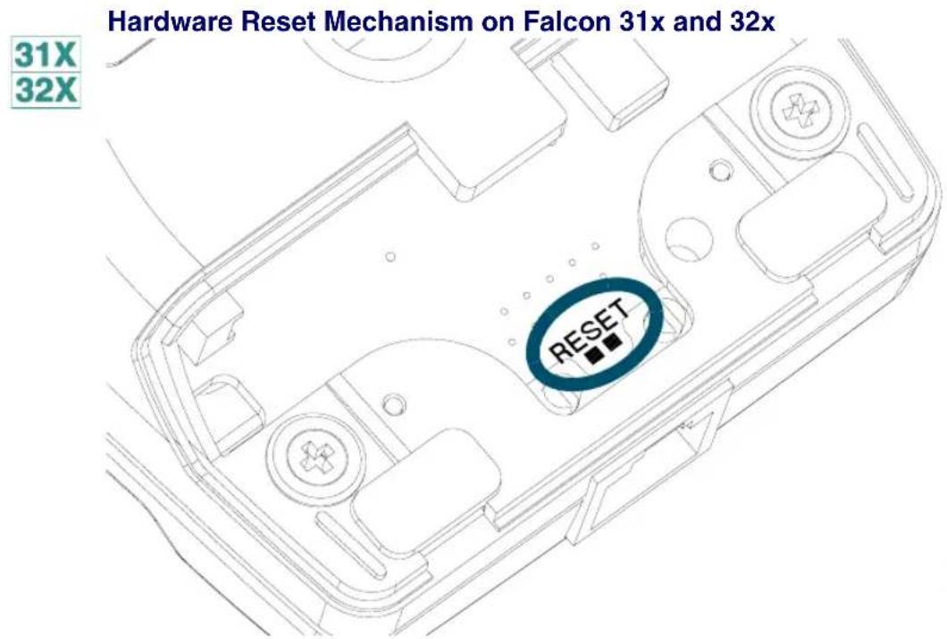
text_image
Hardware Reset Mechanism on Falcon 31x and 32x 31X 32X RESETFigure 7-1: Hardware Reset Mechanism for the Falcon 33x/34x (38-key keypad)

text_image
33X 34X Del Tab BkSp Esc 0 Space AB CD EF GH IJ 6 % KL MN OP ?- QR ST Caps & * WX YZ Intl QTL UV O Fn8
Using PC Cards
CHAPTER CONTENTS
Overview....8-2
Uses of PC Cards....8-2
PC Card Drivers 8-3
Overview
PC card support expands the feature set of the Falcon to include:
• Supplemental storage capacity through ATA flash cards
- Modem support
• LAN connectivity
• Radio frequency (RF) communications
Falcon supports Type 1 and Type 2 PC cards. Only one card can be installed in the unit at any one time.
This chapter describes the use of PC cards with the unit. It does not provide details about specific cards, such as communications protocols for fax/modem cards. This type of information should be available from the PC card vendor.
For information about opening the PC card slot cover, inserting and removing PC cards, and card recognition, see the Falcon DOS Portable Terminals User's Guide.
Uses of PC Cards
The primary intended uses for PC cards with the Falcon are expanded storage space and radio frequency (RF) communications. ATA flash memory cards can be added to increase memory. The card appears as a hard drive to the user. RF communications cards allow connection of the portable Falcon unit to a traditional network and to access shared network resources in a transparent fashion. The Falcon can also use network and fax/modem cards.
Use the Falcon Configuration Utility to download the appropriate drivers for ATA and generic I/O cards.
ATA Cards ATA cards are flash memory cards that utilize the IDE interface. This allows the flash to appear as a hard drive. Any ATA PC card should work on the Falcon unit with the appropriate drivers installed. The following ATA cards are approved for use on the Falcon:
• 2.6MB SunDisk Seagate FlashCard, Model ST72P5
• 4MB SanDisk PCMCIA PC CARD ATA
• 8MB SanDisk PCMCIA PC CARD ATA
Additional cards may be approved. Contact a PSC representative for information.
Fax/Modem Cards
The Falcon should recognize any generic fax/modem PC card. Fax/modem PC cards are configured to use COM2, I/O address 2F8h, and IRQ 3. Be aware that many of these cards tend to use a large amount of power and can quickly drain the batteries. The following fax/modem card is approved for use on the Falcon:
Viking Components 36.6K PC Card Modem.

The Falcon does not support fax/modem cards with XJack connectors.
LAN Cards
LAN cards require assignment of an I/O window, a memory window, and an IRQ. If the LAN card will be configured by the superclient driver (pcmscd.exe), additional entries to the pcm.ini file will be necessary. Many LAN cards come with their own resource-management system and do not require the pcmscd.exe driver.

Because of the Falcon's memory-handling properties, some LAN cards may not work. Please contact PSC prior to purchasing a LAN card.
RF Cards
Because of the special requirements of RF environments, PSC is distributing Falcon RF units to qualified customers only. Please contact a PSC representative to see if a specific location is qualified.
PC Card Drivers
To attain compatibility with as many PC cards as possible, the Falcon utilizes card and socket services supplied by Phoenix Technologies. These card and socket services are implemented as installable device drivers and are loaded using the DEVICE= command in the config.sys file.
identifies the PhoenixCARD Manager Plus (PCM+) drivers needed for each type of card. Information about these drivers follows the table. Additional drivers or application programs may be required for some cards, particularly RF, LAN, and fax/modem cards.
Table 8-1: PCM+ Drivers Required for PC Cards
| PCM+ Driver | ATA | Fax/Modem | LAN | RF |
| cnfignam.exe X | X | X | X | |
| pcm.ini X | X | X | X | |
| pcmata.sys X | ||||
| pcmcs.exe X | X | X | X | |
| pcmscd.exe X | See below | |||
| pcmss.exe X | X | X | X | |
- cnfignam.exe identifies the section in the PCM+ configuration file (pcm.ini) that should be loaded as the default.
- pcm.ini is the configuration file for the PC cards.
- pcmata.sys is an ATA-IDE device driver. It communicates with the pcmcs.exe driver to allow the system to access ATA-configured PC cards.
- pcmcs .exe is the card-services driver. Required for all PC cards, it provides an interface between applications and the socket services. It also manages resource allocations for the PC cards.
- pcmscd.exe is referred to as the superclient driver. It uses the pcm.ini file to configure and request system resources for generic PC cards as well as specific cards that have been included in the pcm.ini file. Some PC cards will have specific client drivers to handle configuration; pcmscd.exe should not be used with those cards.
- pcmss.exe is the socket-services driver. Required for all PC cards, it provides an interface to the PC card hardware.
A
Connector Configurations
APPENDIX CONTENTS
Overview...... A-2
Falcon Portable Terminals ...... A-2
Laser-Scanner Connector....A-2
Serial Port Jack....A-3
Serial IR Port A-4
Falcon Dock A-5
25-Pin Connector....A-5
Falcon 4-Slot Dock ...... A-6
Host-Interface Cable....A-7
Dock-Network Cable Jacks....A-7
Overview
Cables for all Falcon products are available from PSC and its resellers. As custom cables may be required for custom uses this appendix provides information about Falcon cables, including diagrams and tables describing the connector configurations for:
• Falcon DOS portable terminals
• The Falcon Dock
• The Falcon 4-Slot Dock
Falcon Portable Terminals

Some Falcon models 31x and 32x have a standard 9-pin connector for scanner input at the top and a 10-pin telephone-style jack in the serial port at the bottom.

Falcon Units with integrated lasers do not have a 9-pin connector at the top of the unit as the integrated laser is located there.
Laser-Scanner Connector
Figure A-1: 9-Pin Connector on the Falcon 31x and 32x


text_image
Pin #1 Pin #5 Pin #6 Pin #9Table A-1: Pinouts for the 9-Pin Connector
| Pin # Signal Notes | ||
| 1 Laser sync in | ||
| 2 Bar code data in | ||
| 3 Good-read out | ||
| 4 Scan-enable out Not normally used | ||
| 5 Laser trigger in | ||
| 6 Laser-scan-enable out | ||
| 7 | GND | |
| 8 | GND | |
| 9 5V out 300mA max | ||
Serial Port Jack
Figure A-2: Serial Port Jack in the Falcon 31x and 32x
31X 32X

text_image
Pin #10 Pin #1Table A-2: Pinouts for the Serial Port Jack in Falcon 31x/32x
| Pin # Signal Notes | ||
| 1 | DCD in | RS-232 |
| 2 5V out | 300mA max | |
| 3 | RXD | RS-232 |
| 4 | HS out | RS-232 |
| 5 | TXD | RS-232 |
| 6 | Battery | Charging input from dock |
| 7 | Ring in | RS-232 |
| 8 | GND | |
| 9 | HS in | RS-232 |
| 10 | GND | |
Serial IR Port
31X 32X
The IR port provides an IR transceiver for sending and receiving half-duplex IR data that meets the IrDA physical layer specifications.
Figure A-3: Serial IR Port and Docking Pads on the Falcon 33x and 34x
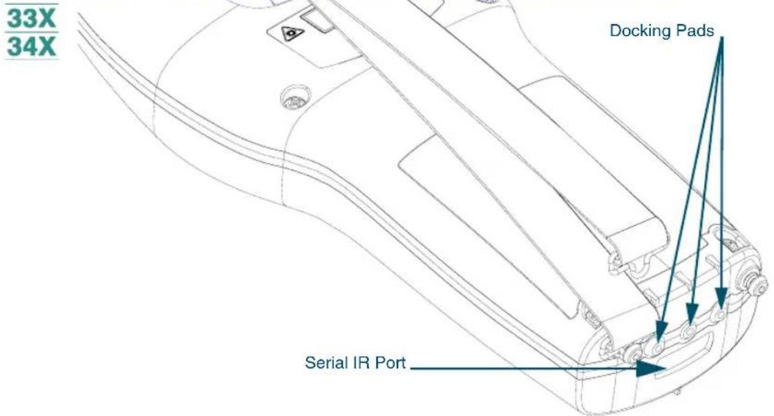
text_image
33X 34X Docking Pads Serial IR PortIn addition, there are three pads along the bottom of the unit. These three pads are used when the Falcon is in the dock. Hold the Falcon oriented with its keypad facing up:
Figure A-4: Docking Pads on the Falcon 33x and 34x
33X 34X
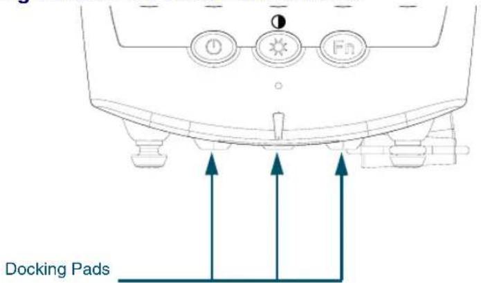
text_image
Docking Pads- The right-most pad is the positive lead and is used for recharging the batteries.
- The center pad is the negative lead and is used for recharging the batteries.
- The left-most pad is used for modified RS-232 input into the Falcon 33x and 34x. This pin serves as RXD while the Falcon is in the dock.
Falcon Dock
25-Pin Connector
Figure A-5 shows the a 25-pin dock-to-host cable connector on the back of the Falcon dock.
Figure A-5: 25-Pin Cable Connector on the Falcon Dock
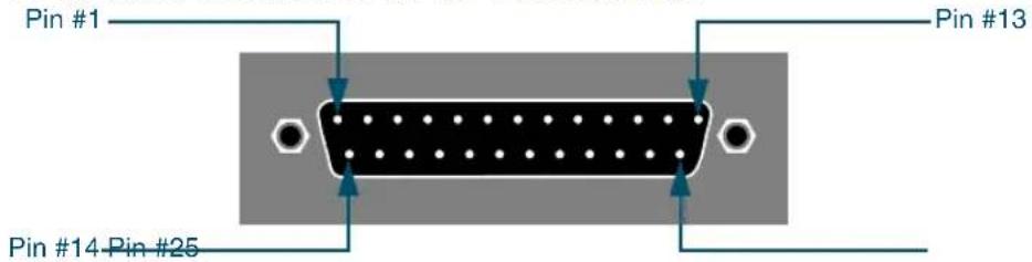
text_image
Pin #1 Pin #13 Pin #14 Pin #25Table A-3: Pinouts for Falcon 31x/32x Dock Cable Connector
| Pin # Signal | |
| 1 | F r |
| 2 | TXD |
| 3 | RXD |
| 4 | RTS |
| 5 | CTS |
| 6 | D ← - - - - |
| 7 | GND connected |
| 8 | DCD |
| 9-19 Unconnected | |
| 20 | DTR ← - - - - |
| 21 | Unconnected |
| 22 | Ring in |
| 23-25 | Unconnected |
S
Table A-4: Pinouts for Falcon 33x/34x Dock Cable Connector
| Pin # Signal | ||
| 1 | F | r |
| 2 Portable TXD | ||
| 3 Portable RXD | ||
| 4 | RTS | ← - - 1 |
| 5 | CTS | ← - - 1 connected |
| 6 | D | ← - - - connected |
| 7 | GND | connected |
| 8 | DCD | ← - - - |
| 9-19 Unconnected | ||
| 20 | DTR | ← - - - connected |
| 21 | Unconnected | |
| 22 | Ring in | ← - - - - |
| 23-25 | Unconnected | |
S
Falcon 4-Slot Dock

The back panel of the Falcon 4-Slot Dock has a 25-pin dock-to-host cable connector and two telephone-style cable jacks: one for “upstream” communications and one for “downstream” communications. The upstream side is the side closer to the host; the downstream side is farther from the host.
Figure A-6: Back Panel of the Falcon 4-Slot Dock
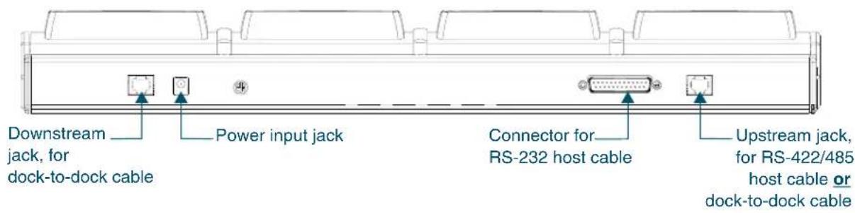
text_image
Downstream jack, for dock-to-dock cable Power input jack Connector for RS-232 host cable Upstream jack, for RS-422/485 host cable or dock-to-dock cableIn a dock network, the first 4-Slot Dock (the one closest to the host) has a cable running from its upstream jack to the host. The second 4-Slot Dock has a cable connecting its upstream jack to the downstream jack on the first 4-Slot Dock. Each additional 4-Slot Dock is connected similarly. The last 4-Slot Dock in the network has nothing plugged into its downstream jack.
Host-Interface Cable
The wiring for the Falcon 4-Slot Dock RS-232 host-interface cable is shown in Table A-5. The standard cable is 6 feet (2 meters) long.
Table A-5: Wiring for the Falcon 4-Slot Dock Host-Interface Cable
| Host Pin # | Host Signal | 45D Pin # (25-pin) | Notes | |
| (9-pin) (25-pin) | ||||
| shell 1/shell Chassis | GND 1/shell | |||
| 3 2 HostTxD# 3 Dock to host | ||||
| 2 3 HostRxD# 2 Host to dock | ||||
| 7 | 4 | HostRTS | 5 | Pins 4, 5, and 8 tied together inside 4-Slot Dock |
| 8 | 5 | HostCTS | 4 | |
| 6 | 6 | HostDSR | 20 | Pins 6 and 20 tied together inside 4-Slot Dock; must be active to select RS-232 interface |
| 4 | 20 | Host DTR | 6 | |
Dock-Network Cable Jacks
The wiring for the dock network cable jacks are shown in Table A-6. The network signals are differential type and are routed on twisted-pair wiring. The pinouts are assigned so as to accommodate certain off-the-shelf cables (e.g., L-COM #TRD855-* EIA568 Flex patch cables).
In the signal names, “in” and “out” refer to the logical direction of the signal with respect to the 4-Slot Dock.
Table A-6: Wiring for the Falcon 4-Slot-Dock Network Cable Jacks
| Pin # | Signal | |
| Upstream Connector Downstream Connector | ||
| 1 Vcc Not used | ||
| 2 HostXmtIn+ HostXmtOut+ | ||
| 3 HostXmtIn- HostXmtOut- | ||
| 4 ReqOut+ ReqIn+ | ||
| 5 HostRcvOut+ HostRcvIn+ | ||
| 6 | HostRcvOut- | HostRcvIn- |
| 7 | ReqOut- | ReqIn- |
| 8 | InhIn+ | InhOut+ |
| 9 InhIn- | InhOut- | |
| 10 | GND | Not used |

Vcc and GND connectors are present only on the upstream connector; they are reserved for future use.
B
ROM-DOS Commands
CHAPTER CONTENTS
Command Overview...... B-2
ROM-DOS vs. MS-DOS B-4
Command Descriptions...... B-5
ATTRIB B-6
BUFFERS...... B-7
CHKDSK......B-7
COMMAND B-9
DELTREE B-11
DIR B-12
FCBS...... B-14
FIND B-14
HELP B-15
NEWFILE......B-16
PRINT B-17
SHARE...... B-18
SWITCHES B-19
TREE B-20
VER......B-21
XCOPY B-21
Command Overview
This chapter lists the Datalight ROM-DOS commands that are available in the Falcon. ROM-DOS commands that differ from their MS-DOS equivalents are identified and described.
The information in this chapter is taken from Datalight's ROM-DOS 6.22 User's Guide and is used by permission.
Table B-1 lists the Datalight ROM-DOS commands that are provided with the Falcon and gives a brief description of each command.
Table B-1: DOS Commands Used with the Falcon
| Command Description | |
| ? | A config.sys command. Directs ROM-DOS to pause for confirmation before processing a command. |
| @ Suppresses the display of a single batch file command line. | |
| ; Same as REM. Identifies nonexecuting lines. | |
| ATTRIB Displays or modifies the attributes associated with a file. | |
| BREAK | A config.sys command. Enables or disables the ability to stop program execution at a non-I/O point. |
| BUFFERS A config.sys command. Sets the number of internal data buffers. | |
| CALL Batch subcommand. Invokes execution of a secondary batch file. | |
| CHDIR | CHange DIRectory (also CD). Changes the default directory. |
| CHKDSK | CHecK DiSK. Checks integrity of data on a disk. Displays information. |
| CLS | CLear Screen. Clears all information from the viewport. |
| COMMAND Spawns a second DOS command processor. | |
| COPY Copies files from one storage location to another. | |
| CTTY | Change TeleTYPpe. Changes the default terminal interacting with ROM-DOS. |
| DATE Displays the date from the system's internal calendar and allows revision. | |
| DEL | DELete. Deletes specified files. |
| DELTREE D deletes files and subdirectories including empty subdirectories. | |
| DEVICE | A config.sys command. Installs a device driver into ROM-DOS. |
| DIR | Displays a list of files in a directory. |
| DOS | A config.sys command. Installs ROM-DOS into high-memory area (HMA). |
| ECHO Batch subcommand. Turns on the display of batch execution on the viewport. | |
| Command | Description |
| ERASE Same as DEL. Erases specified files. | |
| EXIT Exits “nested” running of ROM-DOS within another program. | |
| FCBS | A config.sys command. Specifies the number of file control blocks (FCBS) open at one time. |
| FILES | A config.sys command. Sets the maximum number of files that can be open at one time on the system. |
| FIND Works as a filter to display only lines that contain a specified string. | |
| FOR Batch subcommand. Performs one DOS command on a set of files. | |
| GOTO Batch subcommand. Moves control to a specified line in the batch file. | |
| HELP Lists all available ROM-DOS commands along with brief descriptions. | |
| IF Batch subcommand. Performs a command based on a specified condition. | |
| INCLUDE | A config.sys command. Allows instructions in one configuration block to be included with instructions in another configuration block. |
| INSTALL | Loads terminate-and-stay resident (TSR) programs during config.sys processing. |
| LASTDRIVE Sets the maximum number of drives. | |
| MENUDEFAULT | Sets the default menu item choice and time-out value for making a selection. |
| MENUITEM | Specifies an item to be placed in the startup menu displayed during system boot. |
| MKDIR | MaKe DIRectory (also MD). Creates a new subdirectory. |
| NEWFILE Allows continuation of config.sys processing from a new file. | |
| PATH Displays current command search path(s). A new path line can be specified. | |
| PAUSE Batch subcommand. Causes execution to halt until a key is pressed. | |
| PRINT Prints a list of files, up to ten files. | |
| PROMPT | Resets the appearance of the system prompt line. |
| REM | REMark. A batch subcommand for identifying nonexecuting lines. |
| REN | REName. Renames files. |
| RMDIR | ReMove DIRectory (also RM). Deletes a specified subdirectory. |
| SET | Sets environment variables and command processor strings. |
| SHARE Installs the capabilities for file sharing and file locking on the hard disk. | |
| SHELL | Allows selections of an alternate boot program other than the default command.com command processor. |
| SHIFT Batch subcommand. Shifts replaceable parameters one position “to the left.” | |
| SORT Sorts a text file and displays the output to the standard device. | |
| STACKS | Allows for the use of dynamic data stacks to handle interrupts. Note: ROM-DOS does not utilize this command. |
| SUBMENU Defines a menu item that represents a secondary menu. | |
| SWITCHES Allows special config.sys file options. | |
| TIME Displays the current time from the system's internal clock. Allows revision. | |
| TREE Displays the path of each directory on a specified drive. | |
| TYPE Displays the contents of a text file on the viewport. | |
| VER Displays current version of ROM-DOS on the viewport. | |
| VERIFY Displays the current VERIFY state or sets the VERIFY state to on or off. | |
| VOL Displays the volume label on a disk. | |
| XCOPY Copies multiple files and, optionally, subdirectories. | |
ROM-DOS vs. MS-DOS
Table B-2 identifies differences between ROM-DOS commands and their MS-DOS equivalents. For more information, see the individual command descriptions in the next section.
Table B-2: Difference Between ROM-DOS and MS-DOS Commands
| Command | Features Exclusive to ROM-DOS | Features Exclusive to MS-DOS |
| ATTRIB | -C: Clears all file attributes | /S: Processes files in all subdirectories |
| BUFFERS | Allows designation of secondary buffer cache BUFFERS n,m where m is secondary buffer cache | |
| CHKDSK | /C: Corrects errors without user confirmation | |
| COMMAND | Internal command help only | /Y: Steps through batch file specified by /C or /K switchhelp . hlp in MS-DOS includes all commands (external and internal), installable drivers, etc. |
| DIR | /A X: Shows attributes | /O:C and /O:-C: Sorts by compression ratio /C[H]: Displays compression ratio of files compressed using Drivespace or Doublespace |
| FCBS , [minimum number] | ||
| FIND /I: Not case-sensitive | ||
| HELP Requires | command.hlp | MS-DOS requires external file, help.com, but provides more help text |
| NEWFILE ALL Not available with MS-DOS | ||
| /F: Sets maximum number of files | /D:LPTx (Falcon has no parallel port.) /U/M/S/Q | |
| SHARE | /U: Unloads share.exe | /F: space: Allocates space to record |
| SWITCHES /W | ||
| TREE | /A: Indicates no graphics characters for tree symbols | |
| VER | /R: Shows full version and release numberAllows revision of the version number | |
| XCOPY | /Y /-Y: Turns confirmation prompts on or off |
Command Descriptions
This section provides descriptions of the ROM-DOS commands listed in Table. Each entry includes an explanation of the command's purpose, the command entry syntax, remarks, and examples.
Each command also has a label to designate whether it is an internal or external command. Internal commands are part of the command processor program, command.com. These functions are available only while command.com is running. External commands are actually stand-alone utility programs. They
are independent from command.com. Internal commands that are unique to config.sys processing are also identified. These commands can be used only in a config.sys file.
ATTRIB
Type External
Purpose The ATTRIB command either displays or modifies the attribute of a file.
Syntax ATTRIB [+ | -] [option] [filespec]
Remarks The file attributes define the characteristics of a file. They determine if a file may be deleted or modified, or if it is archived. The ATTRIB command is used to manage these file attributes.
Wildcard characters may be used in the ATTRIB filespec.
The ATTRIB command will modify file attributes if modify commands are given to ATTRIB. The modify commands are:
| Command Description | |
| +/- | Add(+) or remove(-) attribute |
| A Archive attribute | |
| C Clear all attributes | |
| H Hidden file attribute | |
| R Read only attribute | |
| S System file attribute | |
If no modify commands are found by ATTRIB, then the files are displayed along with the file names and their current attributes.
Examples ATTRIB will add the read-only attribute to the file myfile.dat.
ATTRIB +r myfile.dat
ATTRIB will remove the read-only attribute and the archive attribute of all files with the DAT extension.
ATTRIB -a -r *.dat
ATTRIB will display the attributes of all files with the DAT extension.
ATTRIB *.dat
BUFFERS
Type config.sys
Purpose ROM-DOS has internal buffers to temporarily hold data read from the disk. Increasing the number of internal buffers will speed system performance.
Syntax BUFFERS = number
Remarks Each buffer used by ROM-DOS requires 512 bytes of RAM. The BUFFERS command will increase or decrease the amount of RAM used by the operating system.
The minimum number of buffers is 2 and the maximum number is 40. If a number less than 2 is given then the number of BUFFERS is set to 2. If a number larger than 40 is given then BUFFERS is set to 40.
Example The following example causes ROM-DOS to have 10 buffers. These 10 buffers will use 5120 bytes of RAM.
BUFFERS = 10
CHKDSK
Type External
Purpose The CHKDSK command checks the disk directories and File Allocation Table (FAT) and displays a disk and memory report.
Syntax CHKDSK [filespec] [/C] [/F] [/V]
Remarks CHKDSK examines a disk and determines if the disk has any errors in the File Allocation Table (FAT) and will optionally fix errors.
Options
The /F option causes CHKDSK to fix errors on the disk if any were found. The errors that can be found are directory or FAT errors. If the /F is not specified then CHKDSK acts as if it will fix the disk, but the corrections will not be written out to the disk.
If errors are detected, a prompt will appear with a message similar to the following:
15 lost allocation units found in 5 chains.
Convert lost chains to files?
Type Y for Yes, and each lost chain will be written to a file in the root directory of the current default drive. Each file will have the name filennnn.chk.nnnn will be a sequential number. The first chain will be in file000.chk. These files can be verified to see if they contain valuable information, and then deleted if desired. Answering N for No to the above prompt, CHKDSK will still make the corrections however the lost chains will not be saved to the disk.
The /C option allows CHKDSK to correct errors without user confirmation. This option must be used along with the /F option for corrections to be made.
The /V option causes CHKDSK to display each path and file as it is processed.
If a file specification is specified, then CHKDSK displays all files matching the specification that have noncontiguous data areas on the disk. Files that are stored in noncontiguous areas, especially .exe files, have slower disk access times. If CHKDSK reports a large number of files with this problem, a utility program that optimizes the files and free space on the disk should be used.
After checking the disk, CHKDSK displays any error messages followed by a report on the state of the disk that was checked. An example of the report is shown below.
Volume ROM-DOS created June 1,1990 1:00a
Volume Serial Number is 190E-4AA2
362496 bytes total disk space
0 bytes in 1 hidden files
6144 bytes in 2 user files
356352 bytes available on disk
655360 bytes total memory
595360 bytes free
CHKDSK does not wait for a disk to be inserted before the checking is initiated nor does it repair any errors.
Examples CHKDSK will check the integrity of drive A. The report will be printed to the console.
CHKDSK a:
CHKDSK will check the integrity of RAM disk D. The report will be saved in a file called drive_d.rpt.
CHKDSK d: >drive_d.rpt
COMMAND
Type External
Purpose Start a new command processor.
Syntax COMMAND [device] [/E:number] [/K:filename] [/P] [/C string] [/MSG]
Remarks This command starts a new copy of the ROM-DOS command processor. The command processor is the program that has all the internal DOS commands in it.
Starting a new command processor will also produce a new environment. The size of the environment is 128 bytes by default, but it can be changed using the /E switch.
Command and its arguments can also be used in a SHELL= statement in the config.sys file. See the full description of SHELL for more details.
Options The device option specifies that command.com should use a different device, such as AUX, for input and output.
The /E:number switch sets the environment size. Number represents the size of the environment in bytes. Number must be in the range from 160 to 32768. All other values will be ignored and the default value of 256 will be used. ROM-DOS will round the value entered up to the nearest multiple of 16.
The /K:filename option tells the command processor to run the specified filename and then display the ROM-DOS command prompt. It is not recommended that this option be used in a CONFIG.SYS SHELL= statement.
The /P switch causes COMMAND not to exit, or in other words, to remain permanent. The /P switch should be used only when command is used in a CONFIG.SYS SHELL statement.
The /c string switch causes COMMAND to execute the command in string and then terminate. The string command can be any internal or external command.
The /MSG option indicates that all error messages should be stored in memory. This option is recommended only for diskette based systems. ROM-DOS keeps many of its error messages in the resident part of COMMAND.COM rather than using valuable memory to store them. If an error message is needed and ROM-DOS has been loaded from a diskette, the message will only be available if the boot disk is still in the drive. By using the /MSG option, the messages will be available in memory at all times. The /P option must be used along with the /MSG option.
Examples
The following command will cause a new copy of COMMAND to be executed. It will perform a DIR command on the C drive and then exit back to the previous Command Processor.
COMMAND /C DIR C:
The following example shows loading of a permanent copy of command with an environment size of 256 bytes.
SHELL=C:\COMMAND.COM/P/E:256
DELTREE
Type External
Purpose The DELTREE command deletes files and subdirectories including empty subdirectories.
Syntax DELTREE [/Y] [filespec] [[filespec][...]]
Remarks The DELTREE command allows the deletion of files and subdirectories in the same step.
The filespec argument(s) indicate the name(s) of the file(s) or directory tree(s) to delete, Wildcards are allowed.
Options The /Y switch prevents DELTREE from prompting before deleting.
Examples The following DELTREE command deletes all files and directories in the tree C:\TEMP:
DELTREE C:\TEMP
Use DELTREE to delete individual files, one at a time, using wildcards. To delete selected files in the current directory, enter:
DELTREE *.*
DELTREE then prompts for each file it finds which allows the choice of individually deleting them.
DIR
TypeInternal
Purpose Displays a list of the files that are in a directory.
Syntax DIR [filespec] [/option]
Remarks The DIR command can be used to list all the files in a directory, or to show the directory entries of specific files. The standard directory display format includes columns for filenames, filename extensions, file sizes, and the dates and times the files were created.
Options /A attributes
The /A option causes the DIR command to display only the files that match the specified filespec and have the given attribute. The table below shows the legal attribute descriptions.
| Letter Description | ||
| A | A | r |
| D Directories | ||
| H Hidden files | ||
| R Read-only files | ||
| S System files | ||
| X Show attributes | ||
c h i v
The dash (-) symbol can be used to negate listed attributes. For example, to select all files that do not have the archive bit set, use the /A -A option.
/B
The /B, or bare, option causes the display to be displayed without volume label, date, time, or size information.
/L
The /L option causes the filenames to be displayed in lowercase.
/P
The /P option selects page mode, which makes ROM-DOS pause the display each time the screen is full. Press any key to go on to the next page of entries.
/0
The /O option causes the filenames to be displayed in sorted order. The sort order can contain one or more of the following letters:
| Letter Description |
| D By date and time newest first |
| E Alphabetic order by extension |
| G Directories grouped before files |
| N Alphabetic order by name |
| S Size, smallest first |
The dash (−) symbol can precede the sort option to reverse the sort order. For example, to sort all files in the directory in reverse alphabetic order, use the /O-N option.
/s
The /S option causes the display to include files in subdirectories also.
/W
Display list in a wide format without date, time, or size.
The DIRCMD environment variable can be used to set the default preferences for the DIR command. The SET command will assign the values to an environment variable. Refer to the SET command section for proper usage. For example, to always have the /P option set for DIR, the statement SET DIRCMD=/P could be used. The default settings in DIRCMD can be overridden by using the minus sign (-) preceding the option. To cancel the paging for a single use of the DIR command, enter DIR /-P.
Examples
To see the directory entries of all files in the current drive and directory, type: DIR
To see all files in the subdirectory MEMOS on drive B, type:
DIR B:\MEMOS
Display all files sorted by file name order.
DIR /ON
Display all hidden files.
DIR /AH
Display all files with a .doc extension, without file sizes, or volume labels.
DIR *.DOC /B
FCBS
Type CONFIG.SYS
Purpose The FCBS command allows the number of file control blocks (FCBs) open at one time to be specified.
Syntax FCBS = number[,minimum number]
Remarks Number specifies the maximum number of FCBs open at any given time. The default for this value is 4. The value for number must be in the range from 1 to 255. The minimum number specifies the minimum number of FCBs to be open at all times. The minimum number argument has the same default and range value as the number argument.
Example Set the maximum number of FCBs to 8 and leave at least 4 open at all times.
FCBS = 8,4
FIND
Type External
Purpose FIND is a filter to display only lines that contain a specified string.
The input to FIND may come from a file, or it may be piped in from another filter or a DOS command.
Syntax FIND [/option] match-string [filespec]
Options The /C option causes FIND to only display the count of lines found with the specified string.
The /N option causes FIND to display the line number of the line found containing the string.
The /V option causes FIND to display the lines that do not contain the string.
The match-string argument specifies the word or group of characters to search for.
The filespec argument specifies the file or group of files to search in. The complete drive and path can be specified. Wildcard characters can be used in the filename.
Examples The following example shows each line in the file JUNK.C that contains the string "printf".
FIND printf junk.c
The following example shows each line in a directory listing that contains a DIR. The command first executes a DOS DIR command with the output piped into the FIND command. The FIND command then displays each line that contains the string “DIR”.
dir | FIND DIR
The following example give a count of the lines in the file MANUAL . TXT that contain the string "ROM-DOS".
FIND /C ROM-DOS MANUAL.TXT
.....MANUAL.TXT: 105
HELP
TypeInternal
Purpose Provides on-line help of each ROM-DOS command.
Syntax HELP
Remarks HELP serves as a memory aid. For complete information about ROM-DOS commands, always consult this manual.
HELP for each command can also be displayed by entering /? following the command name.
The file COMMAND . HLP must be available to use this command.
Examples To list the help of the DIR command, type:
HELP DIR
or
DIR /?
All available batch file commands are also listed by HELP.
NEWFILE
Type CONFIG.SYS
Purpose The NEWFILE command allows continuation of CONFIG.SYS file processing from a new file. The file can be located on in another directory or even on a different drive.
Syntax NEWFILE=filename
Remarks The NEWFILE command is especially useful when the CONFIG.SYS file is located on an inaccessible drive or in ROM. Additional device drivers or instructions can be added easily to the new file and will be processed along with the main CONFIG.SYS file upon starting the system.
When the NEWFILE= instruction is processed, control will be passed from the present file (the one containing the NEWFILE instruction) to the file specified in the command. Any commands placed after the NEWFILE instruction in the original file will not be processed. If for some reason the specified file name can not be located, CONFIG.SYS processing will be terminated (even if
instructions were to be placed after the NEWFILE command) and the remainder of the startup process will be completed.
NEWFILE commands can be nested. The original CONFIG.SYS can call a second set of instructions via the NEWFILE command. The second file can in turn call a third file by using the NEWFILE command, and so on. Be sure that each filename in the successive steps has a unique name, otherwise, an infinite loop will be created as control is passed back to the same file repeatedly.
Each filename given in a NEWFILE command line will have an environment variable of the same name.
Example
The following example will cause instructions in the file NEWCFG.SYS, located in the C:\BIN directory, to be executed as part of the CONFIG.SYS file. The contents of NEWCFG.SYS may include any of the commands listed in this section.
NEWFILE=C:\BIN\NEWCFG.SYS
Type External
Purpose The PRINT utility prints a single file or a list of files.
Syntax PRINT [filespec] [/options]
Remarks Enter between 1 and 32 files for spooling to the printer. The files are output to the device in a spooled manner (while the user performs other operations).
If PRINT is entered without any parameters, then it displays all the files that are in the queue.
The first time PRINT is used the operator is prompted for the device to perform the operation. The following message is used to prompt the operator for the device.
Name of list device [PRN]:
The legal devices for printing are LPT1, LPT2, LPT3, LPT4, COM1, COM2, COM3, COM4, AUX, or PRN.
Options
The /B option allows the user to set the buffer size. The default buffer size is 512 bytes. A larger buffer size causes print to operate faster. The maximum buffer size is 32k bytes and the minimum size 256 bytes. This option is only allowed the first time PRINT is run.
The /C option cancels only the file names listed after the /C command.
The /F option allows the user to set the maximum number of files to be queued up at one time. The default number of files is 10. The minimum is 2 and the maximum is 32. Support for more files is often useful when using wild cards in file names. This option is only allowed the first time PRINT is run (or until the next system reboot).
The /P option causes all files listed after this option to be submitted for printing. This is the default for filenames encountered on the PRINT command line.
The /T option cancels all the files from the print queue (list). Think of this as a terminator.
The /H option will display the help screen.
Examples
PRINT puts three files into the print queue. The first file will start being printed after the command ends.
PRINT FILE1.TXT FILE2.TXT FILE3.TXT
The file FILE2.TXT will be removed from the print queue. All other files in the queue will print normally.
PRINT /C FILE2.TXT
All files in the print queue are canceled. Printing may continue for a short time because of the buffer in the printer.
PRINT /T
SHARE
Type External
Purpose SHARE installs the capabilities for file-sharing and file-locking on the hard disk.
Syntax SHARE [/options]
Or from CONFIG.SYS:
INSTALL=[drive:] [path] SHARE.EXE [/options]
Remarks The SHARE utility is most commonly used in a network or multitasking environment where file sharing is necessary. When SHARE is loaded, DOS will utilize the SHARE utility to validate read and write requests from application programs and users.
The /L:# option specifies the maximum number of files that can be locked at one time. The default number of files is 20.
The /U option unloads the share utility and frees the memory. SHARE will not unload if other TSRs have been loaded on top of it. The other TSRs must be unloaded first before trying to unload SHARE.
Examples The following example loads the SHARE program from the command line: SHARE
The next example installs SHARE from the CONFIG.SYS file and changes the maximum number of locked files to 30:
INSTALL=C:\UTILS\SHARE.EXE /1:30
The final example unloads SHARE and frees the used memory. SHARE /U
SWITCHES
Type CONFIG.SYS
Purpose The SWITCHES command allows special CONFIG.SYS file options.
Syntax SWITCHES=[/k] [/n] [/f]
Remarks The /k argument makes an enhanced keyboard behave like a conventional-style keyboard.
The /n argument prevents the use of the
The /f argument instructs ROM-DOS to skip the delay after displaying the Starting ROM-DOS... message at boot time. The delay allows the user time to use the F5 and F8 options to alter the processing of the startup files.
Examples The following example prevents the user from using the
switches = /n
TREE
Type External
Purpose The TREE command displays each subdirectory and optionally the files within them for a specified drive.
Syntax TREE [drive:] [/F]
Remarks The TREE command displays the full path of each subdirectory on a specified disk.
The d: specifies the drive that TREE will display the subdirectories from. This argument must be specified.
Options The /F switch causes TREE to display the files in each subdirectory.
Examples This command will display all subdirectories on drive C.
C:\DATA> TREE C:
This command will display all subdirectories on drive A along with the files within each sub directory.
C:\DATA> TREE A: /F
VER
TypeInternal
Purpose Displays the version number of ROM-DOS in use. Allows revision of this version number.
Syntax VER [n.nn] [/R]
Remarks If a new version number is specified, two digits after the decimal are required. Note that this command revises only the record of the DOS version number; it does not change the actual operating system loaded in the computer.
The version command shows both the version of the VER command itself and the version of DOS in operation.
Options The /R option shows the full version and release number of ROM-DOS.
Example The following example changes the record of current DOS version in use to DOS 5.0. Any programs that are executed, following this command, will recognize that DOS 5.0 is running.
VER 5.0
XCOPY
Type External
Purpose The XCOPY command copies multiple files and optionally subdirectories from one disk to another.
Syntax XCOPY [source] [target] [/options]
Remarks The XCOPY command is used for copying multiple files and subdirectories, if they exist.
The source and the target parameter are complete drive path and file specification descriptions. If a path is not specified, XCOPY assumes the default path. If a file name is not specified then *. * is assumed.
The ATTRIB command may be used to modify the archive bit for the various XCOPY options that check the archive status of files. Refer to the ATTRIB command description for instructions.
Options
The /A copies only source files that have the archive bit set in them. The archive is not reset.
The /D
The /E option causes XCOPY to create subdirectories on the target even if they are empty.
The /M option causes XCOPY to copy only those source files that have the archive bit set. Once the source file is copied the archive bit is reset.
The /P option causes XCOPY to prompt before each file is copied. The prompt appears as follows:
C:\COMMAND.COM (Y/N)?
If a Y is entered then the file is copied, otherwise, the file is not copied.
The /S option causes XCOPY to copy files in subdirectories of the source directory.
The /V option causes XCOPY to verify each write to the disk.
The /W option causes XCOPY to wait before starting to copy files. The following prompt is displayed.
Press any key to begin copying file(s)
Example
XCOPY to the A drive all files in the BIN subdirectory that have an EXE extension and that have the archive bit set.
XCOPY \bin*.exe a: /a
C
Programming Parameters
APPENDIX CONTENTS
Code 39 B-3
Interleaved 2 of 5 ...... B-3
Matrix 2 of 5...... B-3
Standard 2 of 5 B-3
Code 11 B-4
Codabar/Ames B-4
MSI...... B-4
Code 93 B-4
Universal Product Code-A (UPC-A) ...... B-4
Universal Product Code-E (UPC-E) ...... B-5
European Article Numbering (EAN) / Japan Article Numbering (JAN) B-5
UPC, EAN, JAN Extensions...... B-5
Code 128 B-5
Labelcode 4/5 B-5
Other Controls B-5
Overview
This appendix contains information about programmable settings for the Falcon. Use the Falcon Configuration Utility in Chapter 2 or the bar codes provided in Appendix D to program the Falcon.
Table I on page C-2 provides the following information:
- Code Parameter is the “human” name for the programming option.
- I.D. # is the “decoder” name for the programming option. For example, to set a Code 39 minimum label length, use I.D. #01. Programming I.D. numbers given in this appendix can be used with all programming methods.
- Type tells what kind of setting to use for each code parameter.
- On/Off is a toggle. 1 turns the parameter on, and 0 turns it off.
- Value requires a two-character entry (e.g., 02 for two beeps after each good read).
- Acceptable Input gives the settings or range of settings for each code parameter.
- Defaults tells how the parameter is set when the predefined default D0, D1, or D2 is selected.
- Predefined Default 0 (D0) turns every on/off parameter off and sets all minimum and maximum lengths to the lowest values.
- Predefined Default 1 (D1) turns every on/off parameter on, sets all minimum lengths to the lowest values, and sets all maximum lengths to the highest values. This default set is normally used only for troubleshooting. It gives the best chance of reading an unknown bar code symbology and also identifies the symbology of each bar code scanned.
- Predefined Default 2 (D2) is the default set that was installed in the Falcon at the factory. This default set will work for most applications. To reset the Falcon to the original defaults, scan the D2 bar code on page D-2.
Table C-1: Parameters, Settings and Defaults
| Code Parameter I.D. # Type | Acceptable Input | Defaults | ||||
| D0 D1 | D2 | |||||
| Code 39 Enter 1 for On and 0 for Off. | ||||||
| Enable 00 On/Off On or Off Off On On | ||||||
| Minimum length 01 Value 00-50 00 00 | 00 | |||||
| Maximum length | 02 Value 01-50 01 | 50 20 | ||||
| Enable checksum | 03 | On/Off | On or Off | Off | Off | Off |
| Send checksum | 04 | On/Off | On or Off | Off | Off | Off |
| Full ASCII mode | 05 | On/Off | On or Off | Off | On | On |
| Interleaved 2 of 5 Enter 1 for On and 0 for Off. | ||||||
| Enable 08 On/Off On or Off Off On On | ||||||
| Minimum length 09 Value 02-50 02 | 02 06 | |||||
| Maximum length | 0A | Value 02-50 02 | 50 10 | |||
| Enable checksum | 0B | On/Off | On or Off | Off | Off | Off |
| Send checksum | 0C | On/Off | On or Off | Off | Off | Off |
| Use lengths 6 and 14 only (case code) | 0D | On/Off | On or Off | Off | Off | Off |
| Matrix 2 of 5 Enter 1 for On and 0 for Off. | ||||||
| Enable 10 On/Off On or Off Off On Off | ||||||
| Minimum length 11 Value 01-50 01 | 01 06 | |||||
| Maximum length | 12 Value 01-50 01 | 50 10 | ||||
| Enable checksum | 13 | On/Off | On or Off | Off | Off | Off |
| Send checksum | 14 | On/Off | On or Off | Off | Off | Off |
| Standard 2 of 5 Enter 1 for On and 0 for Off. | ||||||
| Enable 15 On/Off On or Off Off On Off | ||||||
| Minimum length 16 Value 01-50 01 | 01 06 | |||||
| Maximum length | 17 Value 01-50 01 | 50 10 | ||||
| Enable checksum | 18 | On/Off | On or Off | Off | Off | Off |
| Send checksum | 19 | On/Off | On or Off | Off | Off | Off |
| Use 2-bar start/stop | 1A | On/Off | On or Off | Off | Off | Off |
| Code Parameter | I.D. # | Type | Acceptable Input | Defaults | ||
| D0 D1 | D2 | |||||
| Code 11 Enter 1 for On and 0 for Off. | ||||||
| Enable 1B On/Off On or Off Off On Off | ||||||
| Minimum length 1C Value 01-50 01 01 04 | ||||||
| Maximum length 1D Value 01-50 01 50 10 | ||||||
| Require 2 check digits 1E On/Off On or Off Off Off Off Off Off Off Off Off Off Off Off Off Off Off Off Off Off Off Off Off Off Off Off Off Off Off Off Off Off Off Off Off Off Off Off Off Off Off Off Off Off Off Off Off Off Off Off Off Off Off Off Off Off Off Off Off Off Off Off Off Off Off Off Off Off Off Off Off Off Off Off Off Off Off Off Off Off Off Off Off Off Off Off Off Off Off Off Off Off Off Off Off Off Off Off Off Off Off Off | 51 | On/Off | On or Off | Off | On | Off |
| Codabar Enable | 20 | On/Off | On or Off | Off | On | On |
| Codabar Enable | 21 | Value 01-50 01 01 04 | ||||
| Maximum length | 22 | Value 01-50 01 50 20 | ||||
| Send start/stop | 23 | On/Off | On or Off | Off | On | Off |
| Codabar-to-CLSI conversion | 24 | On/Off | On or Off | Off | Off | Off |
| Wide intercharacter gaps allowed | 25 | On/Off | On or Off | Off | Off | On |
| MSI Enter 1 for On and 0 for Off. | ||||||
| Enable | 26 | On/Off | On or Off | Off | On | Off |
| Minimum length | 27 | Value 01-14 01 01 04 | ||||
| Maximum length | 28 | Value 01-14 01 14 10 | ||||
| Require 2 check digits | 29 | On/Off | On or Off | Off | Off | Off |
| 2nd check digit Mod 11 | 2A | On/Off | On or Off | Off | Off | Off |
| Send check digit(s) | 2B | On/Off | On or Off | Off | On | Off |
| Code 93 Enter 1 for On and 0 for Off. | ||||||
| Enable 2C On/Off On or Off Off On Off | ||||||
| Minimum length 2D Value 01-50 01 01 02 | ||||||
| Maximum length 2E Value 01-50 01 50 20 | ||||||
| Universal Product Code-A (UPC-A) Enter 1 for On and 0 for Off. | ||||||
| Enable | 30 | On/Off | On or Off | Off | On | On |
| Send system digit | 31 | On/Off | On or Off | Off | On | On |
| Send check digit | 32 | On/Off | On or Off | Off | On | Off |
| Convert UPC-A to EAN-13 | 33 | On/Off | On or Off | Off | On | Off |
| Universal Product Code-E (UPC-E) Enter 1 for On and 0 for Off. | ||||||
| Use system digit 0 34 On/Off On or Off | Off On On | |||||
| Use system digit 1 35 On/Off On or Off | Off On On | |||||
| Convert UPC-E to UPC-A 36 On/Off On | On or Off Off | On Off | ||||
| Send system digit 37 On/Off On or Off | Off On Off | |||||
| Send check digit 38 On/Off On or Off | Off On Off | |||||
| European Article Numbering (EAN) /Japan Article Numbering (JAN) Enter 1 for On and 0 for Off. | ||||||
| Enable EAN-8/JAN-8 39 On/Off On or | Off Off On | On | ||||
| Enable EAN-13/JAN-13 | 3A | On/Off | On or Off | Off | On | On |
| Convert EAN-13 to ISBN | 3B | On/Off | On or Off | Off | Off | Off |
| Send EAN/JAN checksum | 3F | On/Off | On or Off | Off | Off | Off |
| UPC, EAN, JAN Extensions Enter 1 for On and 0 for Off. | ||||||
| Allow 2-digit extensions 3C On/Off On | or Off Off | On On | ||||
| Allow 5-digit extensions 3D On/Off On | or Off Off | On On | ||||
| Require extensions | 3E | On/Off | On or Off | Off | Off | Off |
| Code 128 Enter 1 for On and 0 for Off. | ||||||
| Enable | 40 | On/Off | On or Off | Off | On | On |
| Minimum length | 41 | Value | 01–50 | 01 | 01 | 02 |
| Maximum length | 42 | Value | 01–50 | 01 | 50 | 20 |
| Enable UCC/EAN 128 | 43 | On/Off | On or Off | Off | Off | Off |
| Labelcode 4/5 Enter 1 for On and 0 for Off. | ||||||
| Enable | 52 | On/Off | On or Off | Off | On | Off |
| Convert | 53 On/Off On or Off Off Off Off Off | |||||
| Other Controls Enter 1 for On and 0 for Off. | ||||||
| Laser programming enable | B0 | On/Off | On or Off | On | On | On |
| Autoterminator | B1 | Value | Any single ASCII character (00 = Off) | (CR) | (CR) | (CR) |
| Auto-off timer | B2 | Value | 01–99 (in 4-sec.increments)(00 = Off) | 75 75 | 75 | |
| Send assigned symbology identifiers**A = UPC-A D = M 2 of 5 G = EAN-8 J = Code 11 M = EAN-13B = I 2 of 5 E = UPC-E H = MSI K = Code 128 N = Labelcode 4/5C = Code 39 F = S 2 of 5 I = Codabar L = Code 93 O = Ames | B5 | On/Off | On or Off | Off | On | Off |
| Good-read beep tone B8 Value 00 | = 2400 Hz | 01 = 2600 Hz02 = 2800 Hz03 = 3000 Hz04 = 3200 Hz05 = 3400 Hz06 = 3600 Hz07 = 3800 Hz | 00 | 00 | 00 | |
| Number of good-read beeps | B9 | Value | 01–04 | 01 | 01 | 01 |
| Good-read beep duration | BA | Value | 00 = 0.07 sec.01 = 0.13 sec.02 = 0.18 sec.03 = 0.36 sec. | 00 | 00 | 00 |
| Beeper volume | BC | Value | 00 = Off01–09(01 = Lowest;07 = Highest;08 = Higher;09 = Lower) | 07 | 07 | 07 |
| Error beep tone | BD | Value | 00 = 2400 Hz01 = 2580 Hz02 = 2770 Hz03 = 3000 Hz04 = 3270 Hz05 = 3600 Hz06 = 4000 Hz07 = 4520 Hz | 01 | 01 | 01 |
| Long-range trigger mode(long-range scanner models only)Spot beam timeout(long-range scanner models only) | D4D5 Value 00 = 0.25 | On/Off | On = Release ScanOff = Spot Timeoutsec.01 = 0.5 sec.02 = 1 sec.03 = 1.5 sec.04 = 2 sec. | Off01 01 | Off01 | Off |
| Release scan timeout(long-range scanner models only) | D6 Value 01–30 | (seconds) | 02 02 | 02 | ||
| Spotting Beam Enable(long-range scanner models only) | D7 On/Off On or Off | Off On On On | ||||
| Keypress sound DD Value 00 = Off | 01 = Click02 = Beep | 01 01 | 01 | |||
| Enable CTL-ALT-DEL reboot E0 On/Off On or Off Off Off On | ||||||
| Enable trigger programmability(Note that for the Falcon 33x, this will effect Enter key programmability.) | E1 On/Off On or Off Off On On | |||||
| Backlight auto-off timeout | E2 Value 01–99 | (seconds)(00 = Off) | 15 15 | 15 | ||
| Double Action Key Mode(33x models only) | E3 Value 01 = DoubleStrike02 = Press &Wait | 01 01 | 01 | |||
| Double Action Key Timeout(33x models only) | E4 Value 00 = 165 ms.01 = 220 ms.02 = 275 ms.03 = 330 ms.04 = 385 ms.05 = 440 ms.06 = 495 ms.07 = 550 ms.08 = 605 ms.09 = 660 ms. | 03 03 | 03 | |||
NOTES
D
Bar Codes
This appendix provides bar codes for common setup parameters for programming the Falcon. Factory default settings are underlined.
To make settings that aren't provided in this chapter, design custom bar codes or use the Falcon Configuration Utility to program the Falcon (refer to Chapter 2).
APPENDIX CONTENTS
Predefined Defaults...... D-2
Code 39......D-2
Interleaved 2 of 5 D-3
Matrix 2 of 5 D-3
Standard 2 of 5 D-4
Code 11 ...... D-5
Codabar/Ames D-6
MSI D-7
Code 93 D-8
Code 128 D-8
Labelcode 4/5 D-9
UPC-A (Universal Product Code-A) ...... D-9
UPC-E (Universal Product Code-E) D-10
EAN (European Article Numbering)/JAN (Japan Article Numbering)...... D-10
UPC/EAN/JAN Extentions D-11
Other Controls ....D-11
Predefined Defaults
D1

text_image
* + - D 1 E E *D2

text_image
* + - D 2 E E *Code 39
ENABLE
On

text_image
* + 0 0 1 E E *Off

text_image
* + 0 0 0 E E *MINIMUM LENGTH
0

text_image
* + - 0 1 0 0 E E *10

text_image
* + - 0 1 1 0 E E *20

text_image
* + - 0 1 2 0 E E *30

text_image
* + - 0 1 3 0 E E *40

text_image
* + - 0 1 4 0 E E *50

text_image
* + - 0 1 5 0 E E *MAXIMUM LENGTH
1

text_image
* + - 0 2 0 1 E E *10

text_image
* + - 0 2 1 0 E E *20

text_image
* + - 0 2 2 0 E E *30

text_image
* + - 0 2 3 0 E E *40

text_image
* + - 0 2 4 0 E E *50

text_image
* + - 0 2 5 0 E E *ENABLE CHECKSUM
On

text_image
* + - 0 3 1 E E *Off

text_image
* + - 0 3 0 E E *SEND CHECKSUM
On

text_image
* + - 0 4 1 E E *Off

text_image
* + - 0 4 0 E E *FULL ASCII MODE
On

text_image
* + - 0 5 1 E E *Off

text_image
* + - 0 5 0 E E *Interleaved 2 of 5
ENABLE

text_image
On * + - 0 8 1 E E * Off * + - 0 8 0 E E *MINIMUM LENGTH

MAXIMUM LENGTH

text_image
2 * + - 0 A 0 2 E E * 10 * + - 0 A 1 0 E E * 20 * + - 0 A 2 0 E E *
text_image
30 * + - 0 A 3 0 E E * 40 * + - 0 A 4 0 E E * 50 * + - 0 A 5 0 E E *ENABLE CHECKSUM

text_image
On * + - 0 B 1 E E * Off * + - 0 B 0 E E *SEND CHECKSUM

text_image
On * + - 0 C 1 E E * Off * + - 0 C 0 E E *USE LENGTHS 6 AND 14 ONLY (case code)

text_image
On * + - 0 D 1 E E * Off * + - 0 D 0 E E *Matrix 2 of 5
ENABLE

text_image
On * + - 1 0 1 E E *
text_image
Off * + - 1 0 0 E E *MINIMUM LENGTH
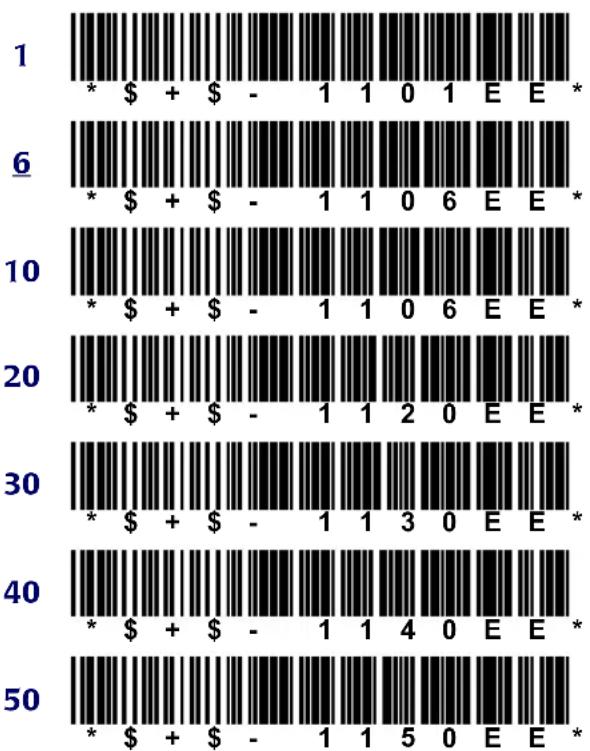
bar
| X-Axis | Bar Type | Value ($) | |---|---|---| | 1 | * | + | | 1 | + | - | | 1 | 1 | 1 | | 1 | 0 | 0 | | 1 | 1 | E | | 1 | E | * | | 6 | * | + | | 6 | + | - | | 6 | 1 | 1 | | 6 | 0 | 6 | | 6 | E | E | | 6 | E | * | | 10 | * | + | | 10 | + | - | | 10 | 1 | 1 | | 10 | 0 | 6 | | 10 | E | E | | 10 | E | * | | 20 | * | + | | 20 | + | - | | 20 | 1 | 1 | | 20 | 2 | 0 | | 20 | E | E | | 20 | E | * | | 30 | * | + | | 30 | + | - | | 30 | 1 | 1 | | 30 | 3 | 0 | | 30 | E | E | | 30 | E | * | | 40 | * | + | | 40 | + | - | | 40 | 1 | 1 | | 40 | 4 | 0 | | 40 | E | E | | 40 | E | * | | 50 | * | + | | 50 | + | - | | 50 | 1 | 1 | | 50 | 5 | 0 | | 50 | E | E | | 50 | E | * |MAXIMUM LENGTH

bar
| ID | Value ($) | |---|---| | 1 | * + - 1 2 0 1 E E * | 10 | * + - 1 2 1 0 E E * | 20 | * + - 1 2 2 0 E E * | 30 | * + - 1 2 3 0 E E * | 40 | * + - 1 2 4 0 E E *
text_image
50 * + - 1 2 5 0 E E *ENABLE CHECKSUM

text_image
On * + - 1 3 1 E E * Off * + - 1 3 0 E E *SEND CHECKSUM

text_image
On * + - 1 4 1 E E * Off * + - 1 4 0 E E *Standard 2 of 5
ENABLE

text_image
On * + - 1 5 1 E E * Off * + - 1 5 0 E E *MINIMUM LENGTH

text_image
1 * + - 1 6 0 1 E E * 6 * + - 1 6 0 6 E E * 10 * + - 1 6 1 0 E E *
bar
| X-Axis Label | Bar 1 () | Bar 2 () | Bar 3 () | Bar 4 () | Bar 5 ($) | |--------------|-----------|-----------|-----------|-----------|-----------| | 20 | * | + | - | 1 | 6 | | 30 | * | + | - | 1 | 6 | | 40 | * | + | - | 1 | 6 | | 50 | * | + | - | 1 | 6 |
text_image
Off * + - 1 9 0 E E * USE 2-BAR START/STOP On * + - 1 A 1 E E * Off * + - 1 A 0 E E *MAXIMUM LENGTH

bar
| X-Axis Label | Bar Type | Value | | :--- | :--- | :--- | | 1 | * | $+ | | 1 | + | $- | | 1 | - | 1 | | 7 | 7 | 0 | | 1 | 1 | E | | 1 | E | * | | 10 | * | $+ | | 10 | + | $- | | 10 | - | 1 | | 7 | 7 | 1 | | 1 | 0 | E | | 1 | E | * | | 20 | * | $+ | | 20 | + | $- | | 20 | - | 1 | | 7 | 2 | 0 | | 1 | E | * | | 20 | * | $+ | | 30 | * | $+ | | 30 | - | 1 | | 7 | 3 | 0 | | 1 | E | * | | 30 | * | $+ | | 40 | * | $+ | | 40 | - | 1 | | 7 | 4 | 0 | | E | E | * | | 40 | * | $+ | | 50 | * | $+ | | 50 | - | 1 | | 7 | 5 | 0 | | E | E | * | * (top) * (bottom)Code 11
ENABLE

text_image
On * + - 1 B 1 E E * Off * + - 1 B 0 E E *ENABLE CHECKSUM

text_image
On * + - 1 8 1 E E * Off * + - 1 8 0 E E *MINIMUM LENGTH

bar
| ID | Value ($) | |---|---| | 4 | * | | 10 | * | | 20 | * | | 30 | * | | 40 | * | | 50 | * |SEND CHECKSUM

text_image
On * + - 1 9 1 E E *MAXIMUM LENGTH

bar
| X-Axis Label | Bar Type | Value ($) | | :--- | :--- | :--- | | 1 | * | + | | 1 | + | - | | 1 | D | 1 | | 1 | 0 | 0 | | 1 | E | 1 | | 1 | E | E | | 10 | * | + | | 10 | + | - | | 10 | D | 1 | | 10 | 1 | 0 | | 10 | E | E | | 20 | * | + | | 20 | + | - | | 20 | D | 2 | | 20 | 0 | E | | 20 | E | E | | 30 | * | + | | 30 | + | - | | 30 | D | 3 | | 30 | 0 | E | | 30 | E | E | | 40 | * | + | | 40 | + | - | | 40 | D | 4 | | 40 | 0 | E | | 40 | E | E | | 50 | * | + | | 50 | + | - | | 50 | D | 5 | | 50 | 0 | E | | 50 | E | E | *REQUIRE 2 CHECK DIGITS

text_image
On * + - 1 E 1 E E * Off * + - 1 E 0 E E *SEND CHECK DIGIT(S)

text_image
On * + - 1 F 1 E E * Off * + - 1 F 0 E E *Codabar/Ames
CODABAR ENABLE

text_image
On * + - 2 0 1 E E *Off

text_image
* + - 2 0 0 E E *AMES ENABLE

text_image
On * + - 5 1 1 E E * Off * + - 5 1 0 E E *MINIMUM LENGTH

bar
| X-Axis Label | Bar Type | Value | | :--- | :--- | :--- | | 1 | * | + - 2 1 0 1 E E * | | 4 | * | + - 2 1 0 4 E E * | | 10 | * | + - 2 1 1 0 E E * | | 20 | * | + - 2 1 2 0 E E * | | 30 | * | + - 2 1 3 0 E E * | | 40 | * | + - 2 1 4 0 E E * | | 50 | * | + - 2 1 5 0 E E * |MAXIMUM LENGTH

text_image
1 * + - 2 2 0 1 E E * 10 * + - 2 2 1 0 E E * 20 * + - 2 2 2 0 E E *
text_image
30 * + - 2 2 3 0 E E * 40 * + - 2 2 4 0 E E * 50 * + - 2 2 5 0 E E *SEND STOP/START

text_image
On * + - 2 3 1 E E * Off * + - 2 3 0 E E *CODABAR-TO-CLSI CONVERSION

text_image
On * + - 2 4 1 E E * Off * + - 2 4 0 E E *WIDE INTERCHARACTER GAPS
ALLOWED

text_image
On * + - 2 5 1 E E * Off * + - 2 5 0 E E *MSI
ENABLE

text_image
On * + - 2 6 1 E E *
text_image
Off * + - 2 6 0 E E *MINIMUM LENGTH
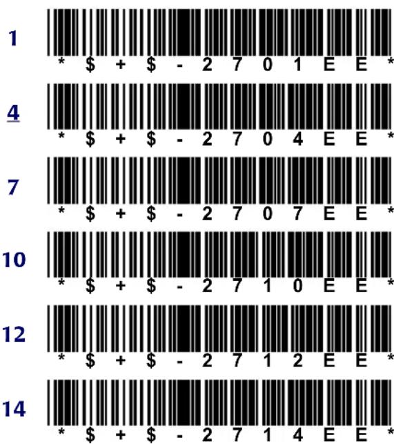
text_image
1 * + - 2 7 0 1 E E * 4 * + - 2 7 0 4 E E * 7 * + - 2 7 0 7 E E * 10 * + - 2 7 1 0 E E * 12 * + - 2 7 1 2 E E * 14 * + - 2 7 1 4 E E *MAXIMUM LENGTH

bar
| Category | Bar Type | Value ($) | | :--- | :--- | :--- | | 1 | * | + | | 1 | + | - | | 1 | 2 | 8 | | 1 | 0 | 1 | | 1 | E | E | | 1 | * | * | | 4 | * | + | | 4 | + | - | | 4 | 2 | 8 | | 4 | 0 | 4 | | 4 | E | E | | 4 | * | * | | 7 | * | + | | 7 | + | - | | 7 | 2 | 8 | | 7 | 0 | 7 | | 7 | E | E | | 7 | * | * | | 10 | * | + | | 10 | + | - | | 10 | 2 | 8 | | 10 | 1 | 0 | | 10 | E | E | | 10 | * | * | | 12 | * | + | | 12 | + | - | | 12 | 2 | 8 | | 12 | 1 | 2 | | 12 | E | E | | 12 | * | * | | 14 | * | + | | 14 | + | - | | 14 | 2 | 8 | | 14 | 1 | 4 | | 14 | E | E | | 14 | * | * |REQUIRE 2 CHECK DIGITS

text_image
On * + - 2 9 1 E E * Off * + - 2 9 0 E E *2ND CHECK DIGIT MOD 11

text_image
On * + - 2 A 1 E E * Off * + - 2 A 0 E E *SEND CHECK DIGIT(S)

text_image
On * + - 2 B 1 E E * Off * + - 2 B 0 E E *Code 93
ENABLE

text_image
On * + - 2 C 1 E E * Off * + - 2 C 0 E E *MINIMUM LENGTH

text_image
2 * + - 2 D 0 2 E E * 10 * + - 2 D 1 0 E E *
text_image
20 * + - 2 D 2 0 E E * 30 * + - 2 D 3 0 E E * 40 * + - 2 D 4 0 E E * 50 * + - 2 D 5 0 E E *MAXIMUM LENGTH

bar
| X-Axis Label | Bar Type | Value ($) | | :--- | :--- | :--- | | 2 | * | + | | 2 | + | - | | 2 | E | 0 | | 2 | 2 | 2 | | 2 | E | 5 | | 2 | 0 | 0 | | 2 | 2 | 2 | | 2 | E | 5 | | 10 | * | + | | 10 | + | - | | 10 | E | 1 | | 10 | 0 | 0 | | 10 | E | 5 | | 10 | * | * | | 20 | * | + | | 20 | + | - | | 20 | E | 2 | | 20 | 0 | 0 | | 20 | E | 5 | | 20 | * | * | | 30 | * | + | | 30 | + | - | | 30 | E | 3 | | 30 | 0 | 0 | | 30 | E | 5 | | 30 | * | * | | 40 | * | + | | 40 | + | - | | 40 | E | 4 | | 40 | 0 | 0 | | 40 | E | 5 | | 40 | * | * | | 50 | * | + | | 50 | + | - | | 50 | E | 5 | | 50 | 0 | 0 | | 50 | E | 5 | | 50 | * | * |Code 128
ENABLE

text_image
On * + - 4 0 1 E E * Off * + - 4 0 0 E E *MINIMUM LENGTH

bar
| Bar | Value ($) | |---|---| | 1 | * + - 4 1 0 1 E E * | 2 | * + - 4 1 0 2 E E * | 10 | * + - 4 1 1 0 E E * | 20 | * + - 4 1 2 0 E E * | 30 | * + - 4 1 3 0 E E * | 40 | * + - 4 1 4 0 E E * | 50 | * + - 4 1 5 0 E E *MAXIMUM LENGTH

bar
| X-Axis | Bar Type | Value | |---|---|---| | 1 | * | + - 4 2 0 1 E E * | | 10 | * | + - 4 2 1 0 E E * | | 20 | * | + - 4 2 2 0 E E * | | 30 | * | + - 4 2 3 0 E E * | | 40 | * | + - 4 2 4 0 E E * | | 50 | * | + - 4 2 5 0 E E * |ENABLE UCC/EAN 128

text_image
On * + - 4 3 1 E E * Off * + - 4 3 0 E E *Labelcode 4/5
ENABLE

text_image
On * + - 5 2 1 E E * Off * + - 5 2 0 E E *CONVERT

text_image
On * + - 5 3 1 E E * Off * + - 5 3 0 E E *UPC-A (Universal Product Code-A)
ENABLE UPC-A

text_image
On * + - 3 0 1 E E * Off * + - 3 0 0 E E *SEND SYSTEM DIGIT

text_image
On * + - 3 1 1 E E *
text_image
Off * + - 3 1 0 E E *SEND CHECK DIGIT

text_image
On * + - 3 2 1 E E * Off * + - 3 2 0 E E *CONVERT UPC-A TO EAN-13

text_image
On * + - 3 3 1 E E * Off * + - 3 3 0 E E *
(Universal Product Code-E)
USE SYSTEM DIGIT 0

text_image
On * + - 3 4 1 E E * Off * + - 3 4 0 E E *USE SYSTEM DIGIT 1

text_image
On * + - 3 5 1 E E * Off * + - 3 5 0 E E *CONVERT UPC-E TO UPC-A

text_image
On * + - 3 6 1 E E *
text_image
Off * + - 3 6 0 E E *SEND SYSTEM DIGIT

text_image
On * + - 3 7 1 E E * Off * + - 3 7 0 E E *SEND CHECK DIGIT

text_image
On * + - 3 8 1 E E * Off * + - 3 8 0 E E *
(European Article Numbering)/

(Japan Article Numbering)
ENABLE EAN-8/JAN-8

text_image
On * + - 3 9 1 E E * Off * + - 3 9 0 E E *ENABLE EAN-13/JAN-13

text_image
On * + - 3 A 1 E E * Off * + - 3 A 0 E E *CONVERT EAN-13 TO ISBN

text_image
On * + - 3 B 1 E E * Off * + - 3 B 0 E E *SEND EAN/JAN CHECKSUM

text_image
On * + - 3 F 1 E E * Off * + - 3 F 0 E E *UPC/EAN/JAN Extentions
ALLOW 2-DIGIT EXTENSIONS

text_image
On * + - 3 C 1 E E * Off * + - 3 C 0 E E *ALLOW 5-DIGIT EXTENSIONS

text_image
On * + - 3 D 1 E E * Off * + - 3 D 0 E E *REQUIRE EXTENSIONS

text_image
On * + - 3 E 1 E E * Off * + - 3 E 0 E E *Other Controls
AUTOTERMINATOR

text_image
(CR) * + - B 1 $ M E E * (TAB) * + - B 1 $ I E E * None * + - B 1 % U E E *AUTO-OFF TIMER
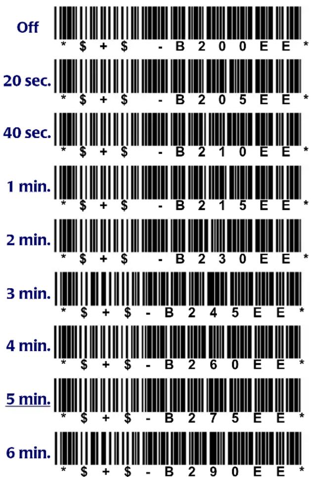
bar
| Timeframe | Period | Value ($) | | :--- | :--- | :--- | | Off | Off | * | | Off | Off | + | | Off | Off | $ | | Off | Off | $ | | Off | Off | - | | Off | Off | B | | Off | Off | 2 | | Off | Off | 0 | | Off | Off | E | | Off | Off | E | | Off | Off | * | | 20 sec. | 20 sec. | * | | 20 sec. | 20 sec. | $ | | 20 sec. | 20 sec. | $ | | 20 sec. | 20 sec. | - | | 20 sec. | 20 sec. | B | | 20 sec. | 20 sec. | 2 | | 20 sec. | 20 sec. | 0 | | 20 sec. | 20 sec. | 5 | | 20 sec. | 20 sec. | E | | 20 sec. | 20 sec. | E | | 40 sec. | 40 sec. | * | | 40 sec. | 40 sec. | $ | | 40 sec. | 40 sec. | $ | | 40 sec. | 40 sec. | - | | 40 sec. | 40 sec. | B | | 40 sec. | 40 sec. | 2 | | 40 sec. | 40 sec. | 0 | | 40 sec. | 40 sec. | 5 | | 40 sec. | 40 sec. | E | | 40 sec. | 40 sec. | E | * | | 1 min. | 1 min. | * | | 1 min. | 1 min. | $ | | 1 min. | 1 min. | $ | | 1 min. | 1 min. | $ | | 1 min. | 1 min. | - | | 1 min. | 1 min. | B | | 1 min. | 1 min. | 2 | | 1 min. | 1 min. | 1 | | 1 min. | 1 min. | 5 | | 1 min. | 1 min. | E | | 1 min. | 1 min. | E | * | | 2 min. | 2 min. | * | | 2 min. | 2 min. | $ | | 2 min. | 2 min. | $ | | 2 min. | 2 min. | - | | 2 min. | 2 min. | B | | 2 min. | 2 min. | 2 | | 2 min. | 2 min. | 1 | | 2 min. | 2 min. | 5 | | 2 min. | 2 min. | E | | 2 min. | 2 min. | E | * | | 3 min. | 3 min. | * | | 3 min. | 3 min. | $ | | 3 min. | 3 min. | $ | | 3 min. | 3 min. | $ | | 3 min. | 3 min. | - | | 3 min. | 3 min. | B | | 3 min. | 3 min. | 2 | | 3 min. | 3 min. | 4 | | 3 min. | 3 min. | 5 | | 3 min. | 3 min. | E | | 3 min. | 3 min. | E | * | | 4 min. | 4 min. | * | | 4 min. | 4 min. | $ | | 4 min. | 4 min. | $ | | 4 min. | 4 min. | $ | | 4 min. | 4 min. | - | | 4 min. | 4 min. | B | | 4 min. | 4 min. | 2 | | 4 min. | 4 min. | 6 | | 4 min. | 4 min. | 0 | | 4 min. | 4 min. | E | | 4 min. | 4 min. | E | * | | 5 min. | 5 min. | * | | 5 min. | 5 min. | $ | | 5 min. | 5 min. | $ | | 5 min. | 5 min. | $ | | 5 min. | 5 min. | - | | 5 min. | 5 min. | B | | 5 min. | 5 min. | 2 | | 5 min. | 5 min. | 7 | | 5 min. | 5 min. | 5 | | 5 min. | 5 min. | E | | 5 min. | 5 min. | E | * | | 6 min. | 6 min. | * | | 6 min. | 6 min. | $ | | 6 min. | 6 min. | $ | | 6 min. | 6 min. | $ | | 6 min. | 6 min. | - | | 6 min. |* (B) (B) (B) (B) (B) (B) (B) (B) (B) (B) (B) (B) (B) (B) (B) (B) (B) (B) (B) (B) (B) (B) (B) (B) (B) (B) (B) (B) (B) (B) (B) (B) (B) (B) * (B) (B) (B) (B) (B) (B) (B) (B) (B) (B) (B) (B) (B) (B) (B) (B) (B) (B) (B) (B) (B) (B) (E) (E) (E) (E) (E) (E) (E) (E) (E) (E) (E) (E) (E) (E) (E) (E) (E) (E) (E) (E) (E) (E) (E) (E) (E) (E) (E) (E)SEND SYMBOLOGY IDENTIFIER

text_image
On * + - B 5 1 E E * Off * + - B 5 0 E E *GOOD-READ BEEP TONE (in Hertz)

bar
| ID | Value ($) | Number of Numbers | |---|---|---| | 2400 | * | 2400 | | 2400 | + | 2400 | | 2400 | - | 2400 | | 2800 | * | 2800 | | 2800 | + | 2800 | | 2800 | - | 2800 | | 2800 | B | 2800 | | 2800 | 8 | 2800 | | 2800 | 0 | 2800 | | 2800 | 0 | 2800 | | 2800 | E | 2800 | | 2800 | E | 2800 | | 2800 | * | 2800 | | 3200 | * | 3200 | | 3200 | + | 3200 | | 3200 | - | 3200 | | 3200 | B | 3200 | | 3200 | 8 | 3200 | | 3200 | 0 | 3200 | | 3200 | 2 | 3200 | | 3200 | E | 3200 | | 3200 | E | 3200 | | 3600 | * | 3600 | | 3600 | + | 3600 | | 3600 | - | 3600 | | 3600 | B | 3600 | | 3600 | 8 | 3600 | | 3600 | 0 | 3600 | | 3600 | 4 | 3600 | | 3600 | E | 3600 | | 3600 | E | 3600 | | 3600 | * | 3600 | | 3600 | + | 3600 | | 3600 | - | 3600 | | 3600 | B | 3600 | | 3600 | 8 | 3600 | | 3600 | 0 | 3600 | | 36551555555555555555555555555555555555555555555555555555555555555555555555555555555555555555555555555555577777777777777777777777777777777777777777777777777777777777777777777777777777777777781111111111111111111111111111111111111111111111111111111111111111111111111111111111111111111111111111999999999999999999999999999999999999999999999999999999999999999999999999999999999999999999999999999988888888888888888888888888888888888888888888888888888888888888888888888888888888888888888888888888884444444444444444444444444444444444444444444444444444444444444444444444444444444444444444444444444444NUMBER OF GOOD-READ BEEPS

text_image
1 * + - B 9 0 1 E E * 2 * + - B 9 0 2 E E * 3 * + - B 9 0 3 E E * 4 * + - B 9 0 4 E E *bar
| Category | Value ($) | Symbol | |---|---|---| | Off | * | | | Lowest | * | + | | Lowest | - | B C 0 0 E E | | Medium | * | + | | Medium | - | B C 0 1 E E | | Highest | * | + | | Highest | - | B C 0 4 E E | | Higher | * | + | | Higher | - | B C 0 7 E E | | Lower | * | + | | Lower | - | B C 0 9 E E |ERROR BEEP TONE (in Hertz)

bar
| ID | Value ($) | Label | |---|---|---| | 2580 | * | + | | 2580 | - | B | | 2580 | D | 0 | | 2580 | 1 | E | | 2580 | E | * | | 3000 | * | + | | 3000 | - | B | | 3000 | D | 0 | | 3000 | 3 | E | | 3000 | E | * | | 3600 | * | + | | 3600 | - | B | | 3600 | D | 0 | | 3600 | 5 | E | | 3600 | E | * | | 4520 | * | + | | 4520 | - | B | | 4520 | D | 0 | | 4520 | 7 | E | | 4520 | E | * |LONG-RANGE TRIGGER MODE
(On = Release Scan; Off = Spot Timeout)

text_image
On * + - D 4 1 E E *
text_image
Off * + - D 4 0 E E *SPOTTING BEAM ENABLE

text_image
On * + - D 7 1 E E *
text_image
Off * + - D 7 0 E E *SPOT BEAM TIMEOUT (in seconds)

text_image
0.25 * + - D 5 0 0 E E *
text_image
0.5 * + - D 5 0 1 E E *
text_image
1 * + - D 5 0 2 E E *
text_image
1.5 * + - D 5 0 3 E E *
text_image
2 * + - D 5 0 4 E E *RELEASE SCAN TIMEOUT (in seconds)

text_image
1 * + - D 6 0 1 E E *
text_image
2 * + - D 6 0 2 E E *
text_image
3 * + - D 6 0 3 E E *5

text_image
* + - D 6 0 5 E E *10

text_image
* + - D 6 1 0 E E *30

text_image
* + - D 6 3 0 E E *KEYPRESS SOUND

text_image
Off * + - D D 0 0 E E *Click

text_image
* + - D D 0 1 E E *Beep

text_image
* + - D D 0 2 E E *ENABLE CTL-ALT-DEL REBOOT

text_image
On * + - E 0 1 E E *Off

text_image
* + - E 0 0 E E *ENABLE TRIGGER
PROGRAMMABILITY

text_image
On * + - E 1 1 E E *Off

text_image
* + - E 1 0 E E *BACKLIGHT AUTO-OFF TIMEOUT (in seconds)

text_image
Off * + - E 2 0 0 E E *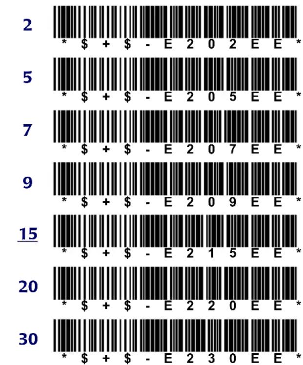
bar
| Bar Number | Symbol | Value ($) | | :--- | :--- | :--- | | 2 | * | + | | 2 | - | E | | 2 | 2 | 2 | | 2 | 0 | 2 | | 2 | E | E | | 2 | * | * | | 5 | * | + | | 5 | - | E | | 5 | 2 | 0 | | 5 | 5 | E | | 5 | E | * | | 7 | * | + | | 7 | - | E | | 7 | 2 | 0 | | 7 | 7 | E | | 7 | E | * | | 9 | * | + | | 9 | - | E | | 9 | 2 | 0 | | 9 | 9 | E | | 9 | E | * | | 15 | * | + | | 15 | - | E | | 15 | 2 | 1 | | 15 | 5 | E | | 15 | E | * | | 20 | * | + | | 20 | - | E | | 20 | 2 | 2 | | 20 | 0 | E | | 20 | E | * | | 30 | * | + | | 30 | - | E | | 30 | 2 | 3 | | 30 | 0 | E | | 30 | E | * |
bar
| Action Mode | Value | | --------------- | ----- | | Double Press | * + - E 3 0 1 E E * | | Press & Wait | * + - E 3 0 2 E E * |DOUBLE KEY ACTION TIMEOUT
(delay in ms)

bar
| X-Axis Label | Bar Type | Value ($) | | :--- | :--- | :--- | | 165 | * | + | | 165 | * | - | | 220 | * | + | | 220 | * | - | | 275 | * | + | | 275 | * | - | | 330 | * | + | | 330 | * | - | | 385 | * | + | | 385 | * | - | | 440 | * | + | | 440 | * | - | | 495 | * | + | | 495 | * | - | | 550 | * | + | | 550 | * | - | | 605 | * | + | | 605 | * | - | | 660 | * | + | | 660 | * | - | | 165 | E | 4 | | 220 | E | 4 | | 275 | E | 4 | | 330 | E | 4 | | 385 | E | 4 | | 440 | E | 4 | | 495 | E | 4 | | 550 | E | 4 | | 605 | E | 4 | | 660 | E | 4 | | 165 | E | 0 | | 220 | E | 0 | | 275 | E | 0 | | 330 | E | 0 | | 385 | E | 0 | | 440 | E | 0 | | 495 | E | 0 | | 550 | E | 0 | | 605 | E | 0 | | 660 | E | 0 | | 165 | E | 9 | | 220 | E | 9 | | 275 | E | 9 | | 330 | E | 9 | | 385 | E | 9 | | 440 | E | 9 | | 495 | E | 9 | | 550 | E | 9 | | 605 | E | 9 | | 660 | E | 9 | * (bar) * (bar) = +; * (bar) = -; * (bar) = -; * (bar) = -; * (bar) = -; * (bar) = -; * (bar) = -; * (bar) = -; * (bar) = -; * (bar) = -; * (bar) = -; * (bar) = -; * (bar) = -; * (bar) = -; * (bar) = -; * (bar) = -; * (bar) = -INDEX
4-1 to 4-6
; (DOS command) B-2
? (DOS command) B-2
@ (DOS command) B-2
@file 3-12, 3-15 to 3-16
4-Slot Dock 4-1 to 4-6
baud rate 4-5
cable configurations A-6 to A-8
device driver (4slot.sys) 4-3
operating modes 4-2
using XFER with 4-4
4slot.sys 4-3
9-pin connector A-2
A
ACCESS_DELAY keyword 3-29
Ames
bar codes for D-6 to D-7
ATA cards 1-4 to 1-8, 8-2
installing drivers with Falcon Configuration
Utility 2-13
ATTRIB B-2, B-4, B-6
autoexec.bat 7-3,7-4
on drive A 5-3
on drive B 5-4, 5-5
on drive C 5-6, 5-9, 5-10, 6-3
auto-off timer
bar codes for D-11 to D-12
settings for C-5
autoterminator
bar codes for D-11
settings for C-5
B
backlight timeout
bar codes for D-14
settings for C-7
bar codes for programming D-1 to D-11
baud rate
for 4-Slot Dock 4-5
setting with the configuration utility 2-21
for XFER 3-12, 3-16
beeper options
bar codes for D-12 to D-13
settings for C-6
BIOS version 5-7
blocks, multiple-option (XFER) 3-27 to 3-29
booting the Falcon 7-1 to 7-6
bparams.ini 6-3
BREAK B-2
BUFFERS B-2, B-4, B-7
C
cable connectors A-1 to A-8
CALL B-2
cards, PC 1-4 to 1-8, 8-1 to 8-4
ATA 8-2
drivers for 8-3
fax/modem 8-3
inserting 1-6 to 1-7
installing drivers with Falcon Configuration
Utility 2-13
LAN 8-3
recognition and configuration 1-7
removing 1-8
RF 8-3
CARRIER TIMEOUT keyword 3-29
cfgdev.sys 5-4, 5-5, 6-3, 7-4
cfgio.exe 6-4
CHDIR B-2
CHKDSK 5-6, B-2, B-4, B-8
chkdsk.com 5-7
CLS B-2
cnfignam.exe 8-4
Codabar
bar codes for D-6 to D-7
Code 11
bar codes for D-5 to D-6
Code 128
bar codes for D-8 to D-9
settings for C-5
Code 39
bar codes for D-2
settings for C-3
Code 93
bar codes for D-8
settings for C-4
codes, error (XFER) 3-34
cold boot 7-3
COM port setting (XFER) 3-12, 3-16
comio.com 5-4,6-5
Comm Settings dialog box (in Falcon
Configuration Utility) 2-20 to 2-21
COMMAND B-2, B-5, B-9
command line syntax (XFER) 3-11
command, modem (XFER) 3-13, 3-19 to 3-20
command.com 5-3,5-7
commands see DOS commands
communications
receive data 3-8
send data 3-8
communications, IR serial
port 1-8
communications, serial
port 1-8
selecting with configuration utility 2-21
COMPRESSION STRINGS keyword 3-29
computer, transferring files to and from 1-11 see also XFER
config.saf 5-3
on drive A 5-3
on drive B 5-4, 5-5
config.sys 5-3,7-3,7-4
on drive A 5-3
on drive B 5-4, 5-5
on drive C 5-6, 5-8, 5-9
configuration of PC cards 1-7
configuration utility see Falcon Configuration Utility
configurations, system software 5-8
configuration-settings file 6-3
configuring the Falcon 1-10, 2-1 to 2-21
connector configurations A-1 to A-8
conversion options
EAN-13 to ISBN C-5
Labelcode 4/5 C-5
UPC-A to EAN-13 C-4
UPC-E to UPC-A C-5
COPY B-2
coreupd.com 5-4
corexfer.exe 5-2
crash recovery (XFER) 3-12, 3-16
CTL+ALT+DEL 7-2
CTL-ALT-DEL
bar code for disabling D-13
CTTY B-2
D
D2 (predefined default set), bar code for D-2
Datalight ROM-DOS 5-7
DATE B-2
decode.sys 5-4, 5-5, 6-6, 7-4
default.cfg 5-8
defaults (predefined), bar code for D-2
DEL B-2
DELTREE B-2
DEVICE B-2
device drivers
cfgdev.sys 5-4
cnfignam.exe 8-4
decode.sys 5-4
flashdsk.sys 5-2,5-4
for PC card 8-3
pcm.ini 8-4
pcmata.exe 8-4
pcmata.sys 8-4
pcmcs.exe 8-4
pcmcsd.exe 8-4
pcmss.exe 8-4
umblink.exe 5-4
vdisk.sys 5-2, 5-4
DIAL METHOD keyword 3-30
DIR B-2, B-5, B-12
DIRCMD environment variable B-13
disk drives 1-9 to 1-10, 5-1 to 5-10
A 5-2, 5-3
additional 5-7
B 1-11
B 5-2, 5-4 to 5-6
C 5-2, 5-6, 7-2, 7-3, 7-4
D 5-2, 5-6 to 5-7, 7-2, 7-3, 7-4
dock, connector configurations A-5 to A-6 DOS
files, installing with Falcon Configuration
Utility 2-13
transferring files in 1-11
version 5-7
DOS B-2
DOS commands B-1 to B-23
; B-2
? B-2
@ B-2
ATTRIB B-2, B-4, B-6
BREAK B-2
BUFFERS B-2, B-4, B-7
CALL B-2
CHDIR B-2
CHKDSK 5-6, B-2, B-4, B-8
CLS B-2
COMMAND B-2, B-5, B-9
COPY B-2
CTTY B-2
DATE B-2
DEL B-2
DELTREE B-2
DEVICE B-2
DIR B-2, B-5, B-12
DOS B-2
ECHO B-3
ERASE B-3
EXIT B-3
FCBS B-3, B-5, B-14
FILES B-3
FIND B-3, B-5, B-15
FOR B-3
GOTO B-3
HELP B-3, B-5, B-16
IF B-3
INCLUDE B-3
INSTALL B-3
LASTDRIVE B-3
MENUDEFAULT B-3
MENUITEM B-3
MKDIR B-3
NEWFILE B-3, B-5, B-16
PATH B-3
PAUSE B-3
PRINT B-3, B-5, B-17
PROMPT B-3
REM B-3
REN B-3
RMDIR B-3
SET B-3
SHARE B-3, B-5, B-19
SHELL B-4
SHIFT B-4
SORT B-4
STACKS B-4
SUBMENU B-4
SWITCHES B-4, B-5, B-20
TIME B-4
TREE B-4, B-5, B-20
TYPE B-4
VER B-4, B-5, B-21
VERIFY B-4
VOL B-4
XCOPY B-4, B-5, B-22
XDEL B-11
drives see disk drives
drop-down lists (in Falcon Configuration Utility) 2-20
E
EAN-13, converting from UPC-A C-4
ECHO B-3
ECHO keyword 3-30
environment variables
DIRCMD B-13
XFER ARGS 3-26 to 3-27
ERASE B-3
error codes (XFER) 3-34
errors, maximum (XFER) 3-12, 3-18
European Article Numbering (EAN)
bar codes for D-10 to D-11
extensions C-5, D-11
settings for C-5
EXIT B-3
extensions (UPC, EAN, and JAN) D-11
settings for C-5
F
FAIL_STRINGS keyword 3-30
Falcon
4-Slot Dock 4-1 to 4-6
baud rate 4-5
cable configurations A-6 to A-8
device driver (4slot.sys) 4-3
operating modes 4-2
using XFER with 4-4
4-Slot Dock 4-1 to 4-6
automatic shutoff
bar codes for D-11
settings for C-5
bar codes for programming D-1 to D-11
booting 7-1 to 7-6
communications port 1-8
configuring 1-10, 2-1 to 2-21
connector configurations A-1 to A-8
disk drives 1-9 to 1-10, 5-1 to 5-10
dock, connector configurations A-5 to A-6
IR serial port 1-8
laser
connector configuration A-2
long-range
bar codes for D-13
settings for C-6 to C-7
pinouts A-1 to A-8
predefined defaults, bar code for D-2
programming parameters C-1 to C-7
rebooting 7-1 to 7-6
serial port 1-8
system utilities 6-1 to 6-14
transferring files to and from 1-11
see also XFER
Falcon Configuration Utility 1-10, 2-1 to 2-21, 5-6
Add button 2-10, 2-23
AUTOEXEC.BAT button 2-16
baud rate setting 2-21
Browse button 2-9, 2-11, 2-12, 2-13, 2-15, 2-16, 2-18, 2-21, 2-23
Comm Port setting 2-21
Comm Settings button 2-4, 2-7
Comm Settings dialog box 2-20 to 2-21
Custom button 2-4
Custom Configuration Menu 2-5
Default button 2-3
Delete button 2-24
Done button 2-15, 2-16, 2-18, 2-20, 2-24
Download button 2-7
drop-down lists 2-20
Edit button 2-24
File Configuration button 2-6
File Configuration windows 2-9 to 2-16
File Transfer window 2-21 to 2-24
input fields 2-17, 2-20
installing 2-2
main menu 2-3
More button 2-13
Next button 2-14, 2-18
on/off switches 2-17, 2-19
Prev button 2-14, 2-16, 2-18, 2-20
Program Settings button 2-7
Program Settings windows 2-16 to 2-20
radio buttons 2-20
Receive button 2-24
Send button 2-24
starting 2-2
Text File button 2-16
Transfer Files button 2-4
Falcon Dock, connector configurations A-5 to A-6
fax/modem cards 1-4 to 1-8, 8-3
installing drivers with Falcon Configuration Utility 2-13
FCBS B-3, B-5, B-14
FCC information 0-xii
File Configuration windows (in Falcon Configuration Utility) 2-9 to 2-16
File Transfer window (in Falcon Configuration Utility) 2-21 to 2-24
filenames (XFER) 3-12, 3-14 to 3-15
FILES B-3
files, system 5-1 to 5-10
also see individual file names
file-transfer protocol 3-14, 3-26
FIND B-3, B-5, B-15
flash memory cards 1-4 to 1-8
installing drivers with Falcon Configuration Utility 2-13
flashdsk.sys 5-2, 5-4, 5-5, 5-6, 6-7
flow control (XFER) 3-12, 3-18 to 3-19
FOR B-3
format.com 5-4,6-8
4-Slot Dock 4-1to 4-6
cable configurations A-6 to A-8
using XFER with 4-4
baud rate 4-5
device driver (4slot.sys) 4-3
operating modes 4-2
Falcon
4-Slot Dock 4-1 to 4-6
functest.com 5-4
G
General Tab 3-3
GOTO B-3
H
HANDSHAKING keyword 3-30
hardware reset 7-5
HELP B-3, B-5, B-16
help for XFER 3-12, 3-19
Host (PC) Settings 3-2
host mode 3-8
host-controlled mode (4-Slot Dock) 4-2, 4-3, 4-5
I
I/O cards 1-4 to 1-8
installing drivers with Falcon Configuration Utility 2-13
identifying symbologies C-6
bar codes for D-12
IF B-3
ignore options (XFER) 3-13, 3-20
INCLUDE B-3
INIT_STRING keyword 3-30
initialization file for modem 3-29 to 3-32
sample 3-32
initialization file, modem (XFER) 3-13, 3-19
input fields (in Falcon Configuration Utility) 2-17, 2-20
INSTALL B-3
installing the Falcon Configuration Utility 2-2
integrated laser, long-range
bar codes for D-13
settings for C-6 to C-7
Interleaved 2 of 5
bar codes for D-3
settings for C-3
IR serial communications
port 1-8
IR serial port 1-8
J
Japan Article Numbering (JAN)
bar codes for D-10 to D-11
extensions C-5, D-11
settings for C-5
K
keypress sound
programming C-7
keywords (in modem-initialization file) 3-29 to 3-32
L
Labelcode 4/5
bar codes for D-9
settings for C-5
LAN cards 8-3
laser
connector configuration A-2
long-range
bar codes for D-13
settings for C-6 to C-7
LASTDRIVE B-3
ld.bat 5-4
using 2-3, 2-8, 2-24
local-area network (LAN) cards 8-3
lock.com 5-4,6-9
LOCKED BAUDRATE keyword 3-30
Logging Tab 3-7
long-range laser
bar codes for D-13
settings for C-6 to C-7
M
Matrix 2 of 5
bar codes for D-3 to D-4
settings for C-3
memory cards 1-4 to 1-8
installing drivers with Falcon Configuration Utility 2-13
MENUDEFAULT B-3
MENUITEM B-3
MKDIR B-3
modem cards 8-3
modem command (XFER) 3-13, 3-19, 3-20
modem-initialization file 3-29 to 3-32
sample 3-32
modem-initialization file (XFER) 3-13, 3-19
modes, operating (4-Slot Dock) 4-2
MSI
bar codes for D-7 to D-8
settings for C-4
multiple-option blocks (XFER) 3-27 to 3-29
N
networking
software for 5-8
NEWFILE B-3, B-5, B-16
9-pin connector A-2
NUMBER# keyword 3-31
0
on/off switches (in Falcon Configuration
Utility) 2-17, 2-19
operating modes (4-Slot Dock) 4-2
options, XFER 3-12 to 3-26
organize.com 5-4,6-10
overwrite options (XFER) 3-13, 3-20
P
PAL 5-8
pal2.exe 5-8
parameters, XFER 3-12 to 3-26
PARAMS device 6-3
PATH B-3
path handling (XFER) 3-13, 3-23
PAUSE B-3
PC card slot 1-5 to 1-8
removing the cover 1-5
PC cards 1-4 to 1-8, 8-1 to 8-4
ATA 8-2
drivers for 8-3
fax/modem 8-3
inserting 1-6 to 1-7
installing drivers with Falcon Configuration
Utility 2-13
LAN 8-3
recognition and configuration 1-7
removing 1-8
RF 8-3
software for 5-8
PC, transferring files to and from 1-11
pcm.ini 8-4
pcmata.sys 8-4
PCMCIA cards see PC cards
pcmcs.exe 8-4
pcmcsd.exe 8-4
pcmscd.exe 8-4
pcmss.exe 8-4
Percon Portable Applications Library (PAL) 5-8
performance issues (XFER) 3-32
pinouts A-1 to A-8
pm.com 5-4,6-11
port, IR serial 1-8
port, serial 1-8
selecting with the configuration utility 2-21
predefined defaults, bar code for D-2
PRINT B-3, B-5, B-17
Program Settings windows (in Falcon
Configuration Utility) 2-16 to 2-20
programming
bar codes for D-1 to D-11
parameters C-1 to C-7
PROMPT B-3
protocol, file transfer 3-14, 3-26
PROTOCOL_STRINGS keyword 3-31
Q
quiet mode (XFER) 3-13, 3-22
R
radio buttons (in Falcon Configuration Utility) 2-20
radio-frequency (RF) cards 8-3
rebooting the Falcon 7-1 to 7-6
receive file
from portable 3-9
receive files (XFER) 3-13, 3-22
recognition of PC cards 1-7
recovery, crash (XFER) 3-12, 3-16
REM B-3
REN B-3
resetting the Falcon 7-1 to 7-6
response file 3-12, 3-15 to 3-16
rev.com 5-3
RF cards 8-3
RMDIR B-3
ROM-DOS
commands see DOS commands
version 5-7
S
safe boot 7-4
send
file to Portable 3-9
send files (XFER) 3-13, 3-24
serial communications
port 1-8
transfer utility 1-11
using 4-Slot Dock 4-1 to 4-6
serial port 1-8
connector configuration A-3
selecting with the configuration utility 2-21
SET B-3
settings, XFER 3-12 to 3-26
SHARE B-3, B-5, B-19
SHELL B-4
SHIFT B-4
shutoff, automatic
bar codes for D-11
settings for C-5
software
networking 5-8
PC card 5-8
system 5-1 to 5-10
configurations 5-8
SORT B-4
STACKS B-4
Standard 2 of 5
bar codes for D-4 to D-5
settings for C-3
starting the Falcon Configuration Utility 2-2
streaming (XFER) 3-14, 3-25
SUBMENU B-4
SWITCHES B-4, B-5, B-20
symbology identifier option
bar codes for D-12
settings for C-6
syntax (XFER) 3-11
system files 5-1 to 5-10
system software 5-1 to 5-10
configurations 5-8
system utilities 6-1 to 6-14
cfgdev.sys 5-5,6-3
cfgio.exe 6-4
chkdsk.com 5-7
comio.com 5-4,6-5
coreupd.com 5-4
decode.sys 6-6
flashdsk.sys 6-7
format.com 5-4,6-8
lock.com 5-4,6-9
organize.com 5-4, 6-10
pm.com 5-4,6-11
rev.com 5-3
vdisk.sys 6-13
xfer.exe 5-4,6-14
T
terminal-demand mode (4-Slot Dock) 4-2, 4-3
TIME B-4
timeout
automatic shutoff
bar codes for D-11
settings for C-5
backlight
bar codes for D-14
settings for C-7
XFER 3-12, 3-17
timer, auto-off
bar codes for D-11
settings for C-5
Transfer Tab 3-5
transfer utility (XFER) 1-11
transferring files between Falcon and PC 1-11
transmit files (XFER) 3-13, 3-24
TREE B-4, B-5, B-20
triggers, enabling programmability
bar codes for D-14
settings for C-7
TYPE B-4
U
umblink.exe 5-4
Universal Product Code (UPC)
conversion options C-4, C-5
extensions D-11
settings for C-5
UPC-A
bar codes for<\$endpage D-10
bar codes for<\$startpage D-9
converting from UPC-E C-5
converting to EAN-13 C-4
settings for C-4
UPC-E
bar codes for D-10
converting to UPC-A C-5
settings for C-5
utilities, system see system utilities
V
variables, environment
DIRCMD B-13
XFER ARGS 3-26 to 3-27
vdisk.sys 5-2, 5-4, 5-5, 6-13
VER B-4, B-5, B-21
VERIFY B-4
version, DOS 5-7
VOL B-4
W
warm boot 7-2
window size (XFER) 3-14, 3-25
X
XCOPY B-4, B-5, B-22
XDEL B-11
XFER 1-11, 3-10 to 3-34
with 4-Slot Dock 4-4
command line 3-11
error codes 3-34
modem-initialization file 3-29 to 3-32
sample 3-32
multiple-option blocks 3-27 to 3-29
parameters 3-12 to 3-26
performance issues 3-32
syntax 3-11
XFER_ARGS environment variable 3-26 to 3-27
xfer.exe 6-14
location on Falcon 5-4
XFER_ARGS environment variable 3-26 to 3-27
Xmodem 3-14, 3-26
Z
Zmodem 3-14, 3-26
DECLARATION OF CONFORMITY
PSC hereby declares that the Equipment specified below has been tested and found compliant to the following Directives and Stan-
Directives: EMC 89/336/EEC
Low Voltage 73/23/EEC
R&TTE 1999/5/EC
Standards
Equipment: EN 55022-A&B:1994/1998 ;EN 50082-1:1992/1998
EN 55024:1998, EN 60825-1:1996, EN60950:1998
Power Supplies: EN55014-1/2:1993/1997, EN61559-1:1997
EN61558-2-6:1997
Radios: ETS 300 328:1995/1996, EN300 826:1997
EN301.489.1/17:2000, EN60950:1992+A4
Equipment Type: Portable Data Terminal Equipment
Product: Falcon Family Models 31X, 32X, 33X, 34X, 51X, PT2000, Single
Dock Stations, and 4-Slot Dock Stations

text_image
Brad WestBrad West
Vice President
Quality and Process Management
PSC, Inc.
959 Terry Street
Eugene, OR 97402
U.S.A.

Peter Lomax
Vice President
Europe, Middle East & Africa
PSC Bar Code Ltd.
Axis 3, Rhodes Way
Watford
Hertfordshire WD24 4TR
UK
CE
Asia Pacific
PSC Hong Kong
Hong Kong
Telephone: [852]-2-584-6210
Fax: [852]-2-521-0291
Australia
PSC Asia Pacific Pty Ltd.
North Ryde, Australia
Telephone: [61] 0 (2) 9878 8999
Fax: [61] 0 (2) 9878 8688
France
PSC S.A.R.L.
LES ULIS Cedex, France
Telephone: [33].01.64.86.71.00
Fax: [33].01.64 46.72.44
Germany
PSC GmbH
Darmstadt, Germany
Telephone: 49 (0) 61 51/93 58-0
Fax: 49 (0) 61 51/93 58 58
Italy
PSC S.p.A.
Vimercate (MI), Italy
Telephone: [39] (0) 39/62903.1
Fax: [39] (0) 39/6859496
Japan
PSC Japan K.K.
Shinagawa-ku, Tokyo, Japan
Telephone: 81 (0)3 3491 6761
Fax: 81 (0)3 3491 6656
Latin America
PSC S.A., INC.
Miami, Florida, USA
Telephone: (305) 539-0111
Fax: (305) 539-0206
United Kingdom
PSC Bar Code Ltd.
Watford, England
Telephone: 44 (0) 1923 809500
Fax: 44 (0) 1923 809 505

www.pscnet.com
PSC Inc.
959 Terry Street
Eugene, OR
Telephone: (541) 683-5700
Fax: (541) 345-7140

text_image
Black and white barcode image with vertical lines and a central dot(02/04)