
System x3100 M4 - Server LENOVO - Free user manual and instructions
Find the device manual for free System x3100 M4 LENOVO in PDF.

| Product Type | Server |
| Brand | Lenovo |
| Model | System x3100 M4 |
| Form Factor | Tower (5U) |
| Processor | Intel Xeon E3-1200 v2 Series (up to 3.7 GHz) |
| Processor Socket | LGA1155 |
| Chipset | Intel C202 |
| Memory Type | DDR3 ECC Unbuffered (UDIMM) |
| Maximum Memory | 32 GB (4 x 8 GB) |
| Memory Slots | 4 (2 DIMM per channel, dual-channel) |
| Hard Drive Bays | 4 x 3.5-inch SATA (hot-swap optional) |
| Storage Controller | Embedded SATA 6 Gbps (RAID 0/1/10) |
| Network Interface | 2x Gigabit Ethernet (Broadcom BCM5719) |
| Expansion Slots | 1x PCIe 3.0 x16, 1x PCIe 3.0 x8, 1x PCIe 3.0 x4 (x8 slot) |
| Power Supply | 350 W fixed (optional redundant 460 W) |
| Dimensions (H x W x D) | 428 mm x 175 mm x 470 mm (16.9 x 6.9 x 18.5 in) |
| Weight (maximum) | 25 kg (55 lb) |
| Operating Temperature | 10°C to 35°C (50°F to 95°F) |
| Humidity (non-condensing) | 8% to 80% |
| Management | IPMI 2.0 with dedicated management port (optional IMM) |
| Operating System Support | Windows Server, Red Hat, SUSE, VMware ESXi |
| Chassis Fans | 3 x 80 mm non-hot-swap (optional upgrade) |
| Warranty | 1-year limited (extendable) |
| Spare Parts Availability | Common parts (PSU, drives, fans) are widely available through Lenovo and third-party vendors |
Frequently Asked Questions - System x3100 M4 LENOVO
User questions about System x3100 M4 LENOVO
0 question about this device. Answer the ones you know or ask your own.
Ask a new question about this device
Download the instructions for your Server in PDF format for free! Find your manual System x3100 M4 - LENOVO and take your electronic device back in hand. On this page are published all the documents necessary for the use of your device. System x3100 M4 by LENOVO.
USER MANUAL System x3100 M4 LENOVO
IBM System x3100 M4 Type 2582
Problem Determination and Service Guide

natural_image
Abstract geometric pattern with diagonal blue lines and shaded segments (no text or symbols)IBM
IBM System x3100 M4 Type 2582
Problem Determination and Service Guide
Note: Before using this information and the product it supports, read the general information in Appendix B, "Notices," on page 297 and the IBM Safety Information, and IBM Environmental Notices and User's Guide on the IBM System x Documentation CD, and the Warranty Information document that comes with the server.
Contents
Safety . . . . . . . . . . . . . . . . . . . . . . . . . . . . . . . . . . . . . . . . . . . . . v i i
Guidelines for trained service technicians . . . . . . . . . . . . . . . v i i i
Inspecting for unsafe conditions . . . . . . . . . . . . . . . . . . . v i i i
Guidelines for servicing electrical equipment . . . . . . . . . . . . . x
Safety statements . . . . . . . . . . . . . . . . . . . . . . . . . . . . . x i
Chapter 1. Start here. 1
Diagnosing a problem. 1
Undocumented problems 3
Chapter 2. Introduction . . . . . . . . . . . . . . . . . . . . . . . . . . . . . . . . . . 5
Related documentation 5
Notices and statements in this document. 6
Features and specifications. 7
Server controls, LEDs, and power . . . . . . . . . . . . . . . . . . 1 1
Front view. 1 1
Rear view 1 4
Server power features 1 5
Internal LEDs, connectors, and jumpers. 1 7
System-board internal connectors 1 7
System-board external connectors. 1 8
System-board LEDs. 1 8
System-board switches and jumpers . . . . . . . . . . . . . . . . 1 9
Chapter 3. Diagnostics 23
Diagnostic tools 2 3
Event logs 2 4
Viewing event logs through the Setup utility 2 4
Viewing event logs without restarting the server. 2 4
Clearing the event logs. 2 6
POST 2 6
POST error codes. 2 6
System-event log 3 9
Integrated management module II (IMM2) error messages . . . . . . . . 3 9
Checkout procedure . . . . . . . . . . . . . . . . . . . . . . . . . . 8 0
About the checkout procedure 80
Performing the checkout procedure . . . . . . . . . . . . . . . . . 8 1
Troubleshooting tables 82
DVD drive problems 8 2
General problems 8 3
Hard disk drive problems 8 3
Intermittent problems. 8 4
Keyboard, mouse, or pointing-device problems. 8 5
Memory problems. 8 6
Microprocessor problems . . . . . . . . . . . . . . . . . . . . . 8 6
Monitor or video problems. 8 7
Optional-device problems 8 9
Power problems 90
Serial port problems 9 1
ServerGuide problems 9 1
Software problems 92
Universal Serial Bus (USB) port problems . . . . . . . . . . . . . . 9 3
Diagnostic programs and messages 9 4
Running the diagnostic programs . . . . . . . . . . . . . . . . . . 9 4
Diagnostic text messages. 9 5
Viewing the test log . . . . . . . . . . . . . . . . . . . . . . . . . . 9 5
Diagnostic messages. 9 5
Recovering the server firmware . . . . . . . . . . . . . . . . . . . 1 4 2
Automated boot recovery (ABR) . . . . . . . . . . . . . . . . . . . 1 4 4
Three boot failure . . . . . . . . . . . . . . . . . . . . . . . . . . 1 4 4
Solving power problems . . . . . . . . . . . . . . . . . . . . . . . 1 4 5
Solving Ethernet controller problems . . . . . . . . . . . . . . . . . 1 4 6
Solving undetermined problems . . . . . . . . . . . . . . . . . . . 1 4 7
Problem determination tips. 1 4 8
Chapter 4. Parts listing, System x3100 M4 Type 2582 . . . . . . . . . 1 5 1
Replaceable server components . . . . . . . . . . . . . . . . . . . 1 5 1
Product recovery CDs. 1 5 9
Power cords. 1 5 9
Chapter 5. Removing and replacing server components ..... 1 6 3
Installation guidelines 1 6 3
System reliability guidelines. 1 6 4
Working inside the server with the power on 165
Handling static-sensitive devices . . . . . . . . . . . . . . . . . . . 1 6 5
Returning a device or component 1 6 5
Removing and replacing consumable parts and Tier 1 CRUs ..... 1 6 6
Removing the side cover. 1 6 6
Installing the side cover 1 6 7
Removing the bezel 1 6 9
Installing the bezel 171
Removing the lower bezel . . . . . . . . . . . . . . . . . . . 1 7 1
Installing the lower bezel . . . . . . . . . . . . . . . . . . . . 1 7 3
Removing the upper bezel 174
Installing the upper bezel. 1 7 5
Removing a ServeRAID adapter . . . . . . . . . . . . . . . . . . 1 7 6
Installing a ServeRAID adapter . . . . . . . . . . . . . . . . . . 1 7 8
Removing and installing internal drives 182
Removing a memory module. 200
Installing a memory module. 2 0 3
Removing the system battery . . . . . . . . . . . . . . . . . . 2 0 7
Installing the system battery 209
Removing the rear system fan . . . . . . . . . . . . . . . . . . 2 11
Installing the rear system fan . . . . . . . . . . . . . . . . . . . . . 2 1 3
Removing the hard disk drive fan duct . . . . . . . . . . . . . . . 2 1 4
Installing the hard disk drive fan duct . . . . . . . . . . . . . . . . 2 1 5
Removing and replacing consumable parts. 2 1 6
Removing and replacing Tier 2 CRUs . . . . . . . . . . . . . . . . . . 2 1 7
Removing the simple-swap backplate . . . . . . . . . . . . . . . 2 1 7
Installing the simple-swap backplate 2 1 9
Removing the hot-swap hard disk drive backplane . . . . . . . . . . 2 2 2
Installing the hot-swap hard disk drive backplane. 2 2 4
Removing the front-panel assembly. 2 2 6
Installing the front-panel assembly 2 2 8
Removing the front USB connector assembly 230
Installing the front USB connector assembly. 2 3 3
Removing the rear adapter retention bracket. 2 3 6
Installing the rear adapter retention bracket . . . . . . . . . . . . . 2 3 7
Removing the hard disk drive cage . . . . . . . . . . . . . . . . 2 3 7
Installing the hard disk drive cage . . . . . . . . . . . . . . . . . 2 3 8
Removing the non-hot-swap power supply . . . . . . . . . . . . . 2 3 9
Installing the non-hot-swap power supply . . . . . . . . . . . . . . 2 4 2
Removing the hot-swap power supply . . . . . . . . . . . . . . . 2 4 3
Installing the hot-swap power supply . . . . . . . . . . . . . . . . 2 4 5
Removing the hot-swap power supply cage . . . . . . . . . . . . . 2 4 7
Installing the hot-swap power supply cage . . . . . . . . . . . . . 2 4 9
Removing and replacing FRUs. 2 5 0
Removing the microprocessor and heat sink. 2 5 0
Installing a microprocessor and heat sink. 2 5 4
Removing the system board. 2 5 8
Installing the system board. 2 6 1
Chapter 6. Configuration information and instructions ..... 2 6 7
Updating the firmware. 2 6 7
Configuring the server. 2 6 8
Using the ServerGuide Setup and Installation CD. 2 6 9
Using the Setup utility . . . . . . . . . . . . . . . . . . . . . . . 2 7 1
Using the Boot Manager program . . . . . . . . . . . . . . . . . 2 7 5
Starting the backup server firmware. 2 7 5
Using the integrated management module II (IMM2). 2 7 5
Using IPMItool . . . . . . . . . . . . . . . . . . . . . . . . . . . 2 7 6
Managing tools and utilities with IMM2 and IBM System x Server Firmware 276
Resetting the IMM2 with the Setup utility . . . . . . . . . . . . . . 2 7 7
LAN over USB . . . . . . . . . . . . . . . . . . . . . . . . . . . 2 7 8
Enabling the Intel Gigabit Ethernet Utility program 281
Configuring the Gigabit Ethernet controller . . . . . . . . . . . . . 2 8 1
Enabling and configuring Serial over LAN (SOL) . . . . . . . . . . . 2 8 1
Using the LSI Configuration Utility program . . . . . . . . . . . . . 2 8 2
Creating a software RAID array of hard disk drives . . . . . . . . . . 2 8 4
Disable a software RAID array of hard disk drives 285
IBM Advanced Settings Utility program. 2 8 5
Updating IBM Systems Director. 2 8 6
Updating the Universal Unique Identifier (UUID) 2 8 6
Updating the DMI/SMBIOS data 2 8 9
Appendix A. Getting help and technical assistance . . . . . . . . . . 2 9 3
Before you call. 2 9 3
Using the documentation. 2 9 4
Getting help and information from the World Wide Web . . . . . . . . . . 294
How to send Dynamic System Analysis data to IBM . . . . . . . . . . . . 2 9 4
Creating a personalized support web page . . . . . . . . . . . . . . . 2 9 4
Software service and support 294
Hardware service and support. 2 9 5
IBM Taiwan product service. 2 9 5
Appendix B. Notices 2 9 7
Trademarks. 2 9 7
Important notes 298
Particulate contamination. 2 9 9
Documentation format. 2 9 9
Telecommunication regulatory statement. 300
Electronic emission notices . . . . . . . . . . . . . . . . . . . . . 3 0 0
Federal Communications Commission (FCC) statement ..... 3 0 0
Industry Canada Class A emission compliance statement. . . . . . . . 300
Australia and New Zealand Class A statement . . . . . . . . . . . . 300
European Union EMC Directive conformance statement . . . . . . . 3 0 1
Germany Class A statement. 301
VCCI Class A statement. 302
Japan Electronics and Information Technology Industries Association (JEITA) statement 302
Korea Communications Commission (KCC) statement ..... 3 0 2
Russia Electromagnetic Interference (EMI) Class A statement ..... 303
People's Republic of China Class A electronic emission statement . . . . 303
Taiwan Class A compliance statement . . . . . . . . . . . . . . . . . 303
Index 305
Safety
Before installing this product, read the Safety Information.
Guidelines for trained service technicians
This section contains information for trained service technicians.
Inspecting for unsafe conditions
Use the information in this section to help you identify potential unsafe conditions in an IBM® product that you are working on. Each IBM product, as it was designed and manufactured, has required safety items to protect users and service technicians from injury. The information in this section addresses only those items. Use good judgment to identify potential unsafe conditions that might be caused by non-IBM alterations or attachment of non-IBM features or options that are not addressed in this section. If you identify an unsafe condition, you must determine how serious the hazard is and whether you must correct the problem before you work on the product.
Consider the following conditions and the safety hazards that they present:
- Electrical hazards, especially primary power. Primary voltage on the frame can cause serious or fatal electrical shock.
•Explosive hazards, such as a damaged CRT face or a bulging or leaking capacitor.
- Mechanical hazards, such as loose or missing hardware.
To inspect the product for potential unsafe conditions, complete the following steps.
-
Make sure that the power is off and the power cord is disconnected.
-
Make sure that the exterior cover is not damaged, loose, or broken, and observe any sharp edges.
-
Check the power cord:
- Make sure that the third-wire ground connector is in good condition. Use a meter to measure third-wire ground continuity for 0.1 ohm or less between the external ground pin and the frame ground.
- Make sure that the power cord is the correct type, as specified in "Power cords" on page 159.
•Make sure that the insulation is not frayed or worn.
-
Remove the cover.
-
Check for any obvious non-IBM alterations. Use good judgment as to the safety of any non-IBM alterations.
-
Check inside the server for any obvious unsafe conditions, such as metal filings, contamination, water or other liquid, or signs of fire or smoke damage.
-
Check for worn, frayed, or pinched cables.
- Make sure that the power-supply cover fasteners (screws or rivets) have not been removed or tampered with.
Guidelines for servicing electrical equipment
Observe the following guidelines when you service electrical equipment:
- Check the area for electrical hazards such as moist floors, nongrounded power extension cords, and missing safety grounds.
- Use only approved tools and test equipment. Some hand tools have handles that are covered with a soft material that does not provide insulation from live electrical currents.
- Regularly inspect and maintain your electrical hand tools for safe operational condition. Do not use worn or broken tools or testers.
- Do not touch the reflective surface of a dental mirror to a live electrical circuit. The surface is conductive and can cause personal injury or equipment damage if it touches a live electrical circuit.
- Some rubber floor mats contain small conductive fibers to decrease electrostatic discharge. Do not use this type of mat to protect yourself from electrical shock.
- Do not work alone under hazardous conditions or near equipment that has hazardous voltages.
- Locate the emergency power-off (EPO) switch, disconnecting switch, or electrical outlet so that you can turn off the power quickly in the event of an electrical accident.
- Disconnect all power before you perform a mechanical inspection, work near power supplies, or remove or install main units.
- Before you work on the equipment, disconnect the power cord. If you cannot disconnect the power cord, have the customer power-off the wall box that supplies power to the equipment and lock the wall box in the off position.
- Never assume that power has been disconnected from a circuit. Check it to make sure that it has been disconnected.
- If you have to work on equipment that has exposed electrical circuits, observe the following precautions:
- Make sure that another person who is familiar with the power-off controls is near you and is available to turn off the power if necessary.
- When you are working with powered-on electrical equipment, use only one hand. Keep the other hand in your pocket or behind your back to avoid creating a complete circuit that could cause an electrical shock.
- When you use a tester, set the controls correctly and use the approved probe leads and accessories for that tester.
- Stand on a suitable rubber mat to insulate you from grounds such as metal floor strips and equipment frames.
- Use extreme care when you measure high voltages.
•To ensure proper grounding of components such as power supplies, pumps, blowers, fans, and motor generators, do not service these components outside of their normal operating locations.
- If an electrical accident occurs, use caution, turn off the power, and send another person to get medical aid.
Safety statements
Important:
Each caution and danger statement in this document is labeled with a number. This number is used to cross reference an English-language caution or danger statement with translated versions of the caution or danger statement in the Safety Informationdocument.
For example, if a caution statement is labeled with "Statement 1", translations for that caution statement are in the SafetyInformationdocument under "Statement 1".
Be sure to read all caution and danger statements in this document before you perform the procedures. Read any additional safety information that comes with the server or optional device before you install the device.
Attention: Use No. 26 AWG or larger UL-listed or CSA certified telecommunication line cord.
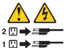
Statement 1:


DANGER
Electrical current from power, telephone, and communication cables is hazardous.
To avoid a shock hazard:
- Do not connect or disconnect any cables or perform installation, maintenance, or reconfiguration of this product during an electrical storm.
- Connect all power cords to a properly wired and grounded electrical outlet.
- Connect to properly wired outlets any equipment that will be attached to this product.
- When possible, use one hand only to connect or disconnect signal cables.
- Never turn on any equipment when there is evidence of fire, water, or structural damage.
- Disconnect the attached power cords, telecommunications systems, networks, and modems before you open the device covers, unless instructed otherwise in the installation and configuration procedures.
- Connect and disconnect cables as described in the following table when installing, moving, or opening covers on this product or attached devices.
To Connect: To Disconnect:
- Turn everything OFF.
- Turn everything OFF.
- First, attach all cables to devices.
- First, remove power cords from outlet.
- Attach signal cables to connectors.
- Remove signal cables from connectors.
- Attach power cords to outlet.
- Remove all cables from devices.
- Turn device ON.
Statement 2:

CAUTION:
When replacing the lithium battery, use only IBM Part Number 33F8354 or an equivalent type battery recommended by the manufacturer. If your system has a module containing a lithium battery, replace it only with the same module type made by the same manufacturer. The battery contains lithium and can explode if not properly used, handled, or disposed of.
Donot:
- Throw or immerse into water
• Heat to more than 100°C (212°F)
•Repair or disassemble
Dispose of the battery as required by local ordinances or regulations.
Statement 3:

CAUTION:
When laser products (such as CD-ROMs, DVD drives, fiber optic devices, or transmitters) are installed, note the following:
- Do not remove the covers. Removing the covers of the laser product could result in exposure to hazardous laser radiation. There are no serviceable parts inside the device.
- Use of controls or adjustments or performance of procedures other than those specified herein might result in hazardous radiation exposure.

DANGER
Some laser products contain an embedded Class 3A or Class 3B laser diode. Note the following.
Laser radiation when open. Do not stare into the beam, do not view directly with optical instruments, and avoid direct exposure to the beam.

Class 1 Laser Product
Laser Klasse 1
Laser Klass 1
Luokan 1 Laserlaite
Use safe practices when lifting.
Statement 5:
CAUTION:
The power control button on the device and the power switch on the power supply do not turn off the electrical current supplied to the device. The device also might have more than one power cord. To remove all electrical current from the device, ensure that all power cords are disconnected from the power source.
Statement 8:


CAUTION:
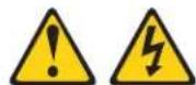
Never remove the cover on a power supply or any part that has the following label attached.
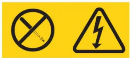
Hazardous voltage, current, and energy levels are present inside any component that has this label attached. There are no serviceable parts inside these components. If you suspect a problem with one of these parts, contact a service technician.
Statement 12:

CAUTION:
The following label indicates a hot surface nearby.

Statement 13:


DANGER
Overloading a branch circuit is potentially a fire hazard and a shock hazard under certain conditions. To avoid these hazards, ensure that your system electrical requirements do not exceed branch circuit protection requirements. Refer to the information that is provided with your device for electrical specifications.
Statement 15:

CAUTION:
Make sure that the rack is secured properly to avoid tipping when the server unit is extended.
Statement 26:

CAUTION:
Do not place any object on top of rack-mounted devices.

Statement 27:

CAUTION:
Hazardous moving parts are nearby.

Statement 35:

CAUTION:
Hazardous energy present. Voltages with hazardous energy might cause heating when shorted with metal, which might result in splattered metal, burns, or both.
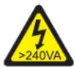
Attention: This server is suitable for use on an IT power-distribution system whose maximum phase-to-phase voltage is 240 V under any distribution fault condition.
United Kingdom - Notice to Customers:
This apparatus is approved under approval number NS/G/1234/J/100003 for indirect connection to public telecommunication systems in the United Kingdom.
Chapter 1. Start here
You can solve many problems without outside assistance by following the troubleshooting procedures in this ProblemDeterminationandServiceGuideand on the IBM website. This document describes the diagnostic tests that you can perform, troubleshooting procedures, and explanations of error messages and error codes. The documentation that comes with your operating system and software also contains troubleshooting information.
Diagnosing a problem
Before you contact IBM or an approved warranty service provider, follow these procedures in the order in which they are presented to diagnose a problem with your server:
1. Return the server to the condition it was in before the problem occurred.
If any hardware, software, or firmware was changed before the problem occurred, if possible, reverse those changes. This might include any of the following items:
•Hardware components
•Device drivers and firmware
- System software
•UEFI firmware
- System input power or network connections
2. View the light path diagnostics LEDs and event logs.
The server is designed for ease of diagnosis of hardware and software problems.
- System-board LEDs: See "System-board LEDs" on page 18 for information about using system-board LEDs.
- Event logs: See "Event logs" on page 24 for information about notification events and diagnosis.
- Software or operating-system error codes: See the documentation for the software or operating system for information about a specific error code. See the manufacturer's website for documentation.
3. Run IBM Dynamic System Analysis (DSA) and collect system data.
Run Dynamic System Analysis (DSA) to collect information about the hardware, firmware, software, and operating system. Have this information available when you contact IBM or an approved warranty service provider. For instructions for running DSA, see the DynamicSystemAnalysisInstallationandUser'sGuide.
To download the latest version of DSA code and the Dynamic System Analysis InstallationandUser'sGuide, go to http://www.ibm.com/support/entry/portal/docdisplay?brand=5000008&Indocid=SERV-DSA.
4. Check for and apply code updates.
Fixes or workarounds for many problems might be available in updated UEFI firmware, device firmware, or device drivers. To display a list of available updates for the server, go to http://www.ibm.com/support/fixcentral/
Important: Some cluster solutions require specific code levels or coordinated code updates. If the device is part of a cluster solution, verify that the latest level of code is supported for the cluster solution before you update the code.
a. Install UpdateXpresssystem updates.
You can install code updates that are packaged as an UpdateXpress System Pack or UpdateXpress CD image. An UpdateXpress System Pack contains an integration-tested bundle of online firmware and device-driver updates for your server. In addition, you can use IBM ToolsCenter Bootable Media Creator to create bootable media that is suitable for applying firmware updates and running preboot diagnostics. For more information about UpdateXpress System Packs, see http://www.ibm.com/support/entry/portal/docdisplay?brand=5000008 &Indocid=SERV-XPRESS and "Updating the firmware" on page 267. For more information about the Bootable Media Creator, see http://www.ibm.com/support/entry/portal/docdisplay?brand=5000008 &Indocid=TOOL-BOMO.
Be sure to separately install any listed critical updates that have release dates that are later than the release date of the UpdateXpressSystem Pack or UpdateXpressimage (see step 4b)
b. Install manual system updates.
1) Determine the existing code levels.
In DSA, click Firmware/VPD to view system firmware levels, or click Software to view operating-system levels.
2) Download and install updates of code that is not at the latest level. To display a list of available updates for the blade server, go to http://www.ibm.com/support/fixcentral/.
When you click an update, an information page is displayed, including a list of the problems that the update fixes. Review this list for your specific problem; however, even if your problem is not listed, installing the update might solve the problem.
5. Check for and correct an incorrect configuration.
If the server is incorrectly configured, a system function can fail to work when you enable it; if you make an incorrect change to the server configuration, a system function that has been enabled can stop working.
a. Make sure that all installed hardware and software are supported.
See http://www.ibm.com/systems/info/x86servers/serverproven/compat/us/ to verify that the server supports the installed operating system, optional devices, and software levels. If any hardware or software component is not supported, uninstall it to determine whether it is causing the problem. You must remove nonsupported hardware before you contact IBM or an approved warranty service provider for support.
b. Make sure that the server, operating system, and software are installed and configured correctly.
Many configuration problems are caused by loose power or signal cables or incorrectly seated adapters. You might be able to solve the problem by turning off the server, reconnecting cables, reseating adapters, and turning the server back on. For information about performing the checkout procedure, see "Checkout procedure" on page 80. For information about configuring the server, see "Configuring the server" on page 268.
6. See controller and management software documentation.
If the problem is associated with a specific function (for example, if a RAID hard disk drive is marked offline in the RAID array), see the documentation for the associated controller and management or controlling software to verify that the controller is correctly configured.
Problem determination information is available for many devices such as RAID and network adapters.
For problems with operating systems or IBM software or devices, go to http://www.ibm.com/supportportal/.
7. Check for troubleshooting procedures and RETAIN tips.
Troubleshooting procedures and RETAIN tips document known problems and suggested solutions. To search for troubleshooting procedures and RETAIN tips, go to http://www.ibm.com/supportportal/.
8. Use the troubleshooting tables.
See “Troubleshooting tables” on page 82 to find a solution to a problem that has identifiable symptoms.
A single problem might cause multiple symptoms. Follow the troubleshooting procedure for the most obvious symptom. If that procedure does not diagnose the problem, use the procedure for another symptom, if possible.
If the problem remains, contact IBM or an approved warranty service provider for assistance with additional problem determination and possible hardware replacement. To open an online service request, go to the http://www.ibm.com/support/entry/portal/Open_service_request/call for service. Be prepared to provide information about any error codes and collected data.
Undocumented problems
If you have completed the diagnostic procedure and the problem remains, the problem might not have been previously identified by IBM. After you have verified that all code is at the latest level, all hardware and software configurations are valid, and no light path diagnostics LEDs or log entries indicate a hardware component failure, contact IBM or an approved warranty service provider for assistance. To open an online service request, go to http://www.ibm.com/support/entry/portal/Open_service_request/. Be prepared to provide information about any error codes and collected data and the problem determination procedures that you have used.
Chapter 2. Introduction
This ProblemDeterminationandServiceGuidecontains information to help you solve problems that might occur in the IBM System x3100 M4 Type 2582 server. It describes the diagnostic tools that come with the server, error codes and suggested actions, and instructions for replacing failing components.
The most recent version of this document is available at http://www.ibm.com/supportportal/.
Replaceable components are of four types:
- Consumable part: Purchase and replacement of consumable parts (components, such as batteries and printer cartridges, that have depletable life) is your responsibility. If IBM acquires or installs a consumable part at your request, you will be charged for the service.
- Tier 1 customer replaceable unit (CRU): Replacement of Tier 1 CRUs is your responsibility. If IBM installs a Tier 1 CRU at your request, you will be charged for the installation.
- Tier 2 customer replaceable unit: You may install a Tier 2 CRU yourself or request IBM to install it, at no additional charge, under the type of warranty service that is designated for the server.
- Field replaceable unit (FRU): FRUs must be installed only by trained service technicians.
For a list of replaceable components for the server, see "Replaceable server components" on page 151.
For information about the terms of the warranty and getting service and assistance, see the WarrantyInformationdocument that comes with the server.
Related documentation
In addition to this document, the following documentation also comes with the server:
•EnvironmentalNoticesandUserGuide
This document is in PDF format on the IBM SystemxDocumentationCD. It contains translated environmental notices.
• IBMLicenseAgreementforMachineCode
This document is in PDF. It contains translated versions of the IBM License Agreement for Machine code for your server.
• IBMWarrantyInformation
This printed document contains the warranty terms and a pointer to the IBM Statement of Limited Warranty on the IBM website.
•InstallationandUser'sGuide
This document is in Portable Document Format (PDF) on the IBM Systemx DocumentationCD. It provides general information about setting up and cabling the server, including information about features, and how to configure the server. It also contains detailed instructions for installing, removing, and connecting some optional devices that the server supports.
•LicensesandAttributionsDocuments
This document is in PDF. It contains information about the open-source notices.
•SafetyInformation
This document is in PDF on the IBM SystemxDocumentationCD. It contains translated caution and danger statements. Each caution and danger statement that appears in the documentation has a number that you can use to locate the corresponding statement in your language in the SafetyInformationdocument.
Depending on the server model, additional documentation might be included on the IBM SystemxDocumentationCD.
The xSeries and BladeCenter Tools Center is an online information center that contains information about tools for updating, managing, and deploying firmware, device drivers, and operating systems. The xSeries and BladeCenter Tools Center is at http://publib.boulder.ibm.com/infocenter/toolsctr/v1r0/index.jsp.
The server might have features that are not described in the documentation that comes with the server. The documentation might be updated occasionally to include information about those features, or technical updates might be available to provide additional information that is not included in the server documentation. These updates are available from the IBM website. To check for updated documentation and technical updates, complete the following steps.
Note: Changes are made periodically to the IBM website. The actual procedure might vary slightly from what is described in this document.
- Go to http://www.ibm.com/supportportal/.
- Under Product support, click System x.
- Under Popular links, click Publications lookup.
- From the Product family menu, select System x3100 M4 and click Continue.
Notices and statements in this document
The caution and danger statements that appear in this document are also in the multilingual SafetyInformationdocument, which is on the IBM xSeries ® DocumentationCD. Each statement is numbered for reference to the corresponding statement in the SafetyInformationdocument.
The following notices and statements are used in this document:
- Note: These notices provide important tips, guidance, or advice.
- Important: These notices provide information or advice that might help you avoid inconvenient or problem situations.
- Attention: These notices indicate potential damage to programs, devices, or data. An attention notice is placed just before the instruction or situation in which damage might occur.
- Caution: These statements indicate situations that can be potentially hazardous to you. A caution statement is placed just before the description of a potentially hazardous procedure step or situation.
- Danger: These statements indicate situations that can be potentially lethal or extremely hazardous to you. A danger statement is placed just before the description of a potentially lethal or extremely hazardous procedure step or situation.
Features and specifications
The following information is a summary of the features and specifications for Machine Type 2582. Depending on the server model, some features might not be available, or some specifications might not apply. See the PDSG on the System x DocumentationCD for additional information about the server.
Table1.Featuresandspecificationsfor4Uservermodelswithnon-hot-swappowersupplies.Forthe5Userver modelwithhot-swappowersupplies(Modelname:2582-F4x),pleaseseeTable2.
| Microprocessor:•Supports one Intel quad-core (Xeon E3-1200 series) or dual-core (Pentium G850, or Core i3 series) processor•Multi-chip Package processor architecture•Designed for LGA 1155 socket•Scalable up to four cores•32 KB instruction L1 cache, 32 KB data L1 cache, 256 KB instruction/data L2 cache, and up to 8 MB L3 cache that is shared among the cores•Support for Intel Extended Memory 64 Technology (EM64T)Note:•Use the Setup utility to determine the type and speed of the microprocessor.•For a list of supported microprocessors, see http://www.ibm.com/servers/eserver/serverproven/compat/us.Memory:•Connectors: four dual inline memory module (DIMM) connectors, two-way interleaved•Minimum: 1 GB•Maximum: 32 GB•Types: PC3-12800 (single-rank or dual-rank), 1066, 1333 and 1600 MHz, ECC, DDR3 unbuffered SDRAM DIMMs only•Sizes: 1GB (single-rank) 2GB (single-rank) 4GB (dual-rank) 8GB (dual-rank) | Fan:•One system fanPower supply: One fixed 350-watt or 300-watt power supplySize:•Height: 360 mm (14.17 in.)•Depth: 480 mm (18.89 in.)•Width: 180 mm (7.08 in.)•Weight: 10 kg (22 lb) to 13 kg (28.66 lb) depending upon configuration | RAID (depending on model):•ServeRAID-BR10il v2 SAS/SATA adapter that provides RAID levels 0, 1, and 10.•ServeRAID-C100 (software RAID) that provides RAID levels 0, 1, and 10.Environment:•Air temperature:– Server on: 10°C to 35°C (50°F to 95°F)Altitude: 0 to 914.4 m (3000 ft)– Server on: 10°C to 32°C (50°F to 89.6°F)Altitude: 914.4 m (3000 ft) to 2133.6 m (7000 ft)– Server on: 10°C to 28°C (50.0°F to 83°F); altitude: 2133.6 m (7000 ft) to 3050 m (10000 ft)– Server off: 10°C to 43°C (50°F to 109.4°F)– Shipping: -40°C to 60°C (-40°F to 140°F)•Humidity (operating and storage): 8% to 80%•Particulate contamination:Attention: Airborne particulates and reactive gases acting alone or in combination with other environmental factors such as humidity or temperature might pose a risk to the server. For information about the limits for particulates and gases, see Particulate contamination on page 299. |
| Drives (depending on the model):•Hard disk drives: up to four 3.5-inch simple-swap SATA•One of the following SATA attached optical drives:– DVD-ROMDrive bays:•Two 5.25-inch half-high bays (one optical drive installed).•Four 3.5-inch hard disk drive bays | Integrated functions:•Integrated management module II (IMM2), which consolidates multiple management functions in a single chip•Intel 82574L Gb Ethernet controller with TCP/IP Offload Engine (TOE) and Wake on LAN support•Integrated SATA controller•Seven Universal Serial Bus (USB) 2.0 ports (two front, four rear of the chassis, and one internal for an optional tape drive)•Six SATA ports (four for simple-swap hard disk drives and two for the DVD drive and the optional tape drive)•One serial port•Two Ethernet port•One VGA port | Heat output:Approximate heat output:•Minimum configuration: 119 Btu per hour (35 watts)•Maximum configuration: 1194 Btu per hour (350 watts)Electrical input:Sine-wave input (50 or 60 Hz) required•Input voltage and frequency ranges automatically selected•Input voltage low range:– Minimum: 100 V ac– Maximum: 127 V ac•Input voltage high range:– Minimum: 200 V ac– Maximum: 240 V ac•Input kilovolt-amperes (kVA) approximately:– Minimum: 0.035 kVA (all models)– Maximum: 0.350 kVA |
| Expansion slots:•One PCI Express x16 slot•One PCI Express x8 slot•One PCI Express x4 slot•One PCI Express x1 slot | Acoustical noise emissions:•Sound power, idling: 4.5 bels•Sound power, operating: 4.8 bels | Notes:1. Power consumption and heat output vary depending on the number and type of optional features installed and the power-management optional features in use.2. The noise emission level stated is the declared (upper limit) sound power level, in bels, for a random sample of machines. All measurements are made in accordance with ISO 7779 and reported in conformance with ISO 9296. |
Table2.Featuresandspecificationsforthe5Uservermodelwithhot-swappowersupplies(Modelname:2582-F4x). For4Uservermodelswithnon-hot-swappowersupplies,pleaseseeTable1.
| Microprocessor:Supports one Intel quad-core (Xeon E3-1200 series) or dual-core (Pentium G850, or Core i3 series) processorMulti-chip Package processor architectureDesigned for LGA 1155 socketScalable up to four cores32 KB instruction L1 cache, 32 KB data L1 cache, 256 KB instruction/data L2 cache, and up to 8 MB L3 cache that is shared among the coresSupport for Intel Extended Memory 64 Technology (EM64T)Note:Use the Setup utility to determine the type and speed of the microprocessor.For a list of supported microprocessors, see http://www.ibm.com/servers/eserver/serverproven/compat/us.Memory:Connectors: four dual inline memory module (DIMM) connectors, two-way interleavedMinimum: 1 GBMaximum: 32 GBTypes: PC3-12800 (single-rank or dual-rank), 1066, 1333 and 1600 MHz, ECC, DDR3 unbuffered SDRAM DIMMs onlySizes: 1GB (single-rank) 2GB (single-rank) 4GB (dual-rank) 8GB (dual-rank) | Fan:One system fanPower supply: One or two redundant 430-watt power supplySize:Height: 438.60 mm (17.27 in.)Depth: 569.11 mm (22.41 in.)Width: 217.25 mm (8.56 in.)Weight: 19.6 kg (43 lb) to 21.4 kg (47 lb) depending upon configuration | RAID (depending on model):ServeRAID-BR10il v2 SAS/SATA adapter that provides RAID levels 0, 1, and 10.Environment:Air temperature:- Server on: 10°C to 35°C (50°F to 95°F)Altitude: 0 to 914.4 m (3000 ft)- Server on: 10°C to 32°C (50°F to 89.6°F)Altitude: 914.4 m (3000 ft) to 2133.6 m (7000 ft)- Server on: 10°C to 28°C (50.0°F to 83°F); altitude: 2133.6 m (7000 ft) to 3050 m (10000 ft)- Server off: 10°C to 43°C (50°F to 109.4°F)- Shipping: -40°C to 60°C (-40°F to 140°F)Humidity (operating and storage): 8% to 80%Particulate contamination:Attention: Airborne particulates and reactive gases acting alone or in combination with other environmental factors such as humidity or temperature might pose a risk to the server. For information about the limits for particulates and gases, see Particulate contamination" on page 299. |
| Drives (depending on the model):Hard disk drives: up to eight 2.5-inch hot-swap SATAOne of the following SATA attached optical drives:- DVD-ROMDrive bays:Two 5.25-inch half-high bays (one optical drive installed).Eight 2.5-inch hard disk drive bays | Integrated functions:Integrated management module II (IMM2), which consolidates multiple management functions in a single chipIntel 82574L Gb Ethernet controller with TCP/IP Offload Engine (TOE) and Wake on LAN supportIntegrated SATA controllerSeven Universal Serial Bus (USB) 2.0 ports (two front, four rear of the chassis, and one internal for an optional tape drive)Six SATA ports (blue-colored ports for DVD drive or optional tape drive)One serial portTwo Ethernet portOne VGA port | Heat output:Approximate heat output:Minimum configuration: 341 Btu per hour (100 watts)Maximum configuration: 1726 Btu per hour (506 watts)Electrical input:Sine-wave input (50 or 60 Hz) requiredInput voltage and frequency ranges automatically selectedInput voltage low range:- Minimum: 100 V ac- Maximum: 127 V acInput voltage high range:- Minimum: 200 V ac- Maximum: 240 V acInput kilovolt-amperes (kVA) approximately:- Minimum: 0.100 kVA (all models)- Maximum: 0.506 kVA |
| Expansion slots:•One PCI Express x16 slot•One PCI Express x8 slot•One PCI Express x4 slot•One PCI Express x1 slot | Acoustical noise emissions:•Sound power, idling: 5.0 bels•Sound power, operating: 5.3 bels | Notes:1. Power consumption and heat output vary depending on the number and type of optional features installed and the power-management optional features in use.2. The noise emission level stated is the declared (upper limit) sound power level, in bels, for a random sample of machines. All measurements are made in accordance with ISO 7779 and reported in conformance with ISO 9296. |
Server controls, LEDs, and power
This section describes the controls, light-emitting diodes (LEDs), and connectors on the front and rear of the server, and how to turn the server on and off. For the location of the LEDs on the system board, see "System-board LEDs" on page 18.
Note: The illustrations in this document might differ slightly from your model.
Front view
The following illustration shows the controls and LEDs on the front of 4U server models with non-hot-swap power supplies.

The following illustration shows the controls and LEDs on the front of the 5U server model with hot-swap power supplies (Model name: 2582-F4x).
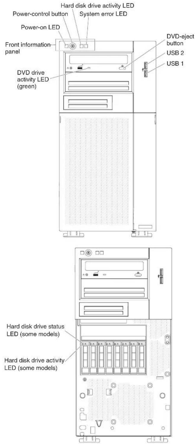
Power control button and power-on LED
Press this button to turn the server on and off manually. The states of the power-on LED are as follows:
Off: AC power is not present, or the power supply or the LED itself has failed.
Flashing rapidly (4 times per second): The server is partially on, but not ready to be fully turned on. The power-control button is disabled. This will last approximately 1 to 3 minutes.
Flashing slowly (once per second): The server is ready to be turned on. You can press the power-control button to turn on the server.
Lit: The server is turned on.
Hard disk drive activity LED
When this LED is flashing, it indicates that the associated hard disk drive is in use.
System-error LED
When this yellow LED is lit, it indicates that a system error has occurred. An LED on the system board might also be lit to help isolate the error.
See Chapter 3, "Diagnostics," on page 23 for additional information.
USB connectors
Connect USB devices to these connectors.
DVD-eject button
Press this button to release a CD or DVD from the DVD drive.
DVD drive activity LED
When this LED is lit, it indicates that the DVD drive is in use.
Hot-swap hard disk drive activity LED (some models)
On some server models, each hot-swap drive has a hard disk drive activity LED. When this green LED is flashing, it indicates that the drive is in use.
When the drive is removed, this LED also is visible on the SAS/SATA backplane, next to the drive connector. The backplane is the printed circuit board behind drive bays 4 through 7 on 3.5-inch hard disk drive models.
Hot-swap hard disk drive status LED (some models)
On some server models, each hot-swap hard disk drive has an yellow status LED. If this yellow status LED for a drive is lit, it indicates that the associated hard disk drive has failed.
If an optional ServeRAID adapter is installed in the server and the LED flashes slowly (one flash per second), the drive is being rebuilt. If the LED flashes rapidly (three flashes per second), the adapter is identifying the drive.
When the drive is removed, this LED also is visible on the SAS/SATA backplane, below the hot-swap hard disk drive activity LED.
Rear view
The following illustration shows the controls and LEDs on the rear of 4U server models with non-hot-swap power supplies.

The following illustration shows the controls and LEDs on the rear of the 5U server model with hot-swap power supplies (Model name: 2582-F4x).
Power connector
Connect the power cord to this connector.
AC power LED
This green LED provides status information about the power supply. During typical operation, both the ac and dc power LEDs are lit.
DC power LED
This green LED provides status information about the power supply. During typical operation, both the ac and dc power LEDs are lit.
Fault-error LED
When this yellow LED is lit, it indicates that the power supply has failed.
Serial connector
Connect a 9-pin serial device to this connector. The serial port is shared with the integrated management module II (IMM2). The IMM2 can take control of the shared serial port to redirect serial traffic, using Serial over LAN (SOL).
Video connector
Connect a monitor to this connector.
USB connectors
Connect USB devices to these connectors.
NMI button
Press this button to force a nonmaskable interrupt to the microprocessor. It allows you to blue screen the server and take a memory dump (use this button only when directed by the IBM service support). You might have to use a pen or the end of a straightened paper clip to press the button.
Ethernet connector
Use either of these connectors to connect the server to a network. When you use the Ethernet 0 connector, the network can be shared with the IMM2 through a single network cable.
Ethernet transmit/receive activity LED
This LED is on the Ethernet connector. When this LED is flashing, it indicates that there is activity between the server and the network.
Ethernet link status LED
This LED is on the Ethernet connector. When this LED is lit, it indicates that there is an active connection on the Ethernet port.
Server power features
When the server is connected to an ac power source but is not turned on, the operating system does not run, and all core logic except for the integrated management module II (IMM2) is shutdown; however, the server can respond to requests from IMM2, such as a remote request to turn on the server. The power-on LED flashes to indicate that the server is connected to ac power but is not turned on.
Turning on the server
Note: Approximately 1 to 3 minutes after the server is connected to ac power, the power-control button becomes active after the power-on LED flashes slowly.
The server can also be turned on in any of the following ways:
- If a power failure occurs while the server is turned on, the server will restart automatically when power is restored.
- If your operating system supports the Wake on LAN feature, the Wake on LAN feature can turn on the server.
Note: When 4 GB or more of memory (physical or logical) is installed, some memory is reserved for various system resources and is unavailable to the operating system. The amount of memory that is reserved for system resources depends on the operating system, the configuration of the server, and the configured peripheral component interconnect (PCI) options.
Turning off the server
When you turn off the server and leave it connected to ac power, the server can respond to requests from IMM2, such as a remote request to turn on the server. While the server remains connected to ac power, one or more fans might continue to run. To remove all power from the server, you must disconnect it from the power source.
Some operating systems require an orderly shutdown before you turn off the server. See your operating-system documentation for information about shutting down the operating system.
Statement 5:
CAUTION:
The power control button on the device and the power switch on the power supply do not turn off the electrical current supplied to the device. The device also might have more than one power cord. To remove all electrical current from the device, ensure that all power cords are disconnected from the power source.


The server can be turned off in any of the following ways:
- You can turn off the server from the operating system, if your operating system supports this feature. After an orderly shutdown of the operating system, the server will be turned off automatically.
- You can press the power-control button to start an orderly shutdown of the operating system and turn off the server, if your operating system supports this feature.
- If the operating system stops functioning, you can press and hold the power-control button for more than 4 seconds to turn off the server.
•The server can be turned off by Wake on LAN feature.
- The integrated management module II (IMM2) can turn off the server as an automatic response to a critical system failure.
Internal LEDs, connectors, and jumpers
The illustrations in this section show the connectors, light-emitting diodes (LEDs), and switches on the system board. The illustrations might differ slightly from your hardware.
Note: The connectors on the system board illustrations might vary slightly from your system board, depending on your server model.
System-board internal connectors
The following illustration shows the internal connectors on the system board.

System-board external connectors
The following illustration shows the external connectors on the system board.
System-board LEDs
The following illustration shows the LEDs on the system board.
Note: When you disconnect the power source from the server, you lose the ability to view the LEDs because the LEDs are not lit when the power source is removed.
Before you disconnect the power source, make a note of which LEDs are lit, including the LEDs that are lit on the operation information panel and LEDs inside the server on the system board.
Table3.SystemboardLEDs
| Component LED Description | |
| DIMM error LEDs A memory DIMM has failed | or is incorrectly installed. |
| Microprocessor/CPU error LED Microprocessor | has failed, is missing, or has been incorrectly installed.Note:(Trained service technician only) Make sure that the microprocessor is installed in the correct sequence; see “installing a microprocessor and heat sink” on page 254. |
| System board error LED System-board CPU VRD and/or power voltage regulators have failed. | |
| IMM heartbeat LED Indicates the status of the | boot process of the IMM2.When the server is connected to power this LED flashes quickly to indicate that the IMM2 code is loading. When the loading is complete, the LED stops flashing briefly and then flashes slowly to indicate that the IMM2 if fully operational and you can press the power-control button to start the server. |
| RTMM heartbeat LED Power-on and power-off sequencing. | |
| Standby power LED When this LED is lit, it indicates that the server is connected to ac power. | |
System-board switches and jumpers
The following illustration shows the jumpers on the system board.

Table4. Systemboardjumpers
| Jumper number Jumper name | Jumper setting | |
| JP1 Clear CMOS jumper | •Pins 1 and 2: Keep CMOS data (default).•Pins 2 and 3: Clear CMOS data. | |
| JP2 BIOS boot backup (boot | block jumper) | •Pins 1 and 2: Boot from primary BIOS page (default).•Pins 2 and 3: Boot from backup BIOS page. |
| JP8 ME recovery jumper | •Pins 1 and 2: Normal (default).•Pins 2 and 3: Activate ME recovery. | |
| JP9 ME flash override jumper | •Pins 1 and 2: Normal (default).•Pins 2 and 3: Override ME flash. | |
| JP10 TPM physical presence | jumper | •Pins 1 and 2: Normal (default).•Pins 2 and 3: Pull down TPM. |
| JP11 TPM initialization jumper | •Pins 1 and 2: Normal (default).•Pins 2 and 3: Initiate TPM. | |
| JP12 IMM SPI half ROM enable | •Pins 1 and 2: Disabled.•Pins 2 and 3: Enable IMM SPI half ROM (default). | |
| JP22 Low security_N jumper | •Pins 1 and 2: Normal (default).•Pins 2 and 3: Activate low security. | |
| Notes:1. If no jumper is present, the server responds as default.2. Changing the position of the boot block jumper from pins 1 and 2 to pins 2 and 3 for 5 seconds before the server is turned on alters which flash ROM page is loaded. Do not change the jumper pin position after the server is turned on. This can cause an unpredictable problem.3. If a message is shown indicating that your Trusted Platform Module's (TPM) physical presence is asserted, it is an indication that the system is vulnerable to potential security risks. This occurs when the jumper setting of JP11 is at Pins 2 and 3. Switching the jumper setting to Pins 1 and 2 of JP11 will deassert the Trusted Platform Module's (TPM) physical presence. | ||
Important:
- Before you change any switch settings or move any jumpers, turn off the server; then, disconnect all power cords and external cables. Review the information in
vii. "Installation guidelines" on page 163, [Handling static-sensitive devices" on page 165, and Turning off the server" on page 16.
- Any system-board switch or jumper blocks that are not shown in the illustrations in this document are reserved.
Chapter 3. Diagnostics
This chapter describes the diagnostic tools that are available to help you solve problems that might occur in the server.
If you cannot locate and correct the problem using the information in this chapter, see Appendix A, "Getting help and technical assistance," on page 293 for more information.
Diagnostic tools
The following tools are available to help you diagnose and solve hardware-related problems:
- POST error messages and error logs
The power-on self-test (POST) generates messages to indicate successful test completion or the detection of a problem. See “POST” on page 26, “Event logs” on page 24, and “POST error codes” on page 26 for more information.
•Troubleshooting tables
These tables list problem symptoms and actions to correct the problems. See "Troubleshooting tables" on page 82 for more information.
•Dynamic System Analysis (DSA) Preboot diagnostic programs
The DSA Preboot diagnostic programs provide problem isolation, configuration analysis, and error log collection. The diagnostic programs are the primary method of testing the major components of the server and are stored in integrated USB memory. The diagnostic programs collect the following information about the server:
– System configuration
– Network interfaces and settings
- Installed hardware
– Vital product data, firmware, and UEFI configuration
- Integrated management module II (IMM2) status and configuration
– Hard disk drive health
- RAID adapter configuration
- Controller and IMM2 event logs, including the following information:
- System error logs
- Temperature, voltage, and fan speed information
- Self-monitoring Analysis, and Reporting Technology (SMART) data
- Machine check registers
- USB information
- Monitor configuration information
- PCI slot information
The diagnostic programs create a merged log that includes events from all collected logs. The information is collected into an XML file that you can send to IBM service and support. Additionally, you can view the server information locally through a generated text report file. You can also copy the outputs (xml.gz, txt, html) to removable media and view the html from a web browser. See “Running the diagnostic programs” on page 94 and “Diagnostic messages” on page 95 for more information.
•Server LEDs
Use the LEDs on the server to diagnose system errors quickly. See "Server controls, LEDs, and power" on page 11 for more information.
•IBM Electronic Service Agent
IBM Electronic Service Agent is a software tool that monitors the server for hardware error events and automatically submits electronic service requests to IBM service and support. In addition, it can collect and transmit system configuration information on a scheduled basis so that the information is available to you and your support representative. It uses minimal system resources, and is available free of charge. For more information and to download IBM Electronic Service Agent, go to http://www.ibm.com/support/entry/portal/Open_service_request/
Event logs
Error codes and messages are displayed in the following types of event logs:
- POST event log: This log contains the three most recent error codes and messages that were generated during POST. You can view the POST event log through the Setup utility.
- System-event log: This log contains messages that were generated during POST and all system status messages from IMM2. You can view the contents of the system-event log from the Setup utility for more information.
The system-event log is limited in size. When it is full, new entries will not overwrite existing entries; therefore, you must periodically clear the system-event log through the Setup utility. When you are troubleshooting, you might have to clear the system-event log to make the most recent events available for analysis.
Each system-event log entry is displayed on its own page. Messages are listed on the left side of the screen, and details about the selected message is displayed on the right side of the screen. To move from one entry to the next, use the Up Arrow ( ) and Down Arrow ( ) keys.
The system-event log indicates an assertion event when an event has occurred. It indicates a de-assertion event when the event is no longer occurring.
- Integrated management module II (IMM2) event log: This log contains a filtered subset of all IMM2, POST, and system management interrupt (SMI) events. You can view the IMM2 event log through the Dynamic System Analysis (DSA) program (as the ASM event log).
- DSA log: This log is generated by the Dynamic System Analysis (DSA) program, and it is a chronologically ordered merge of the system-event log (as the IPMI event log), the IMM2 chassis-event log (as the ASM event log), and the operating-system event logs. You can view the DSA log through the DSA program.
Viewing event logs through the Setup utility
To view the POST event log or system-event log, complete the following steps.
- Turn on the server.
- When the prompt
Setup is displayed, press F1. If you have set both a power-on password and an administrator password, you must type the administrator password to view the event logs. -
Select System Event Logs and use one of the following procedures:
-
To view the POST event log, select POST Event Viewer.
•To view the IMM2 event log, select System Event Log.
Viewing event logs without restarting the server
When the server is not hung and the IMM2 is connected to a network, methods are available for you to view one or more event logs without having to restart the server.
If you have installed Portable Dynamic System Analysis (DSA), you can use it to view the system-event log (as the IPMI event log), the IMM2 event log (as the ASM event log), the operating-system event logs, or the merged DSA log. You can also use DSA Preboot to view these logs, although you must restart the server to use DSA Preboot. To install Portable DSA, DSA Preboot, or to download a DSA Preboot CD image, go to http://www.ibm.com/systems/support/supportsite.wss/docdisplay?Indocid=SERV-DSA&brandind=5000008.
If IPMItool is installed in the server, you can use it to view the system-event log. Most recent versions of the Linux operating system come with a current version of IPMItool. For information about IPMItool, see http://www.ibm.com/developerworks/linux/blueprints/or complete the following steps.
Note: Changes are made periodically to the IBM website. The actual procedure might vary slightly from what is described in this document.
- Go to http://publib.boulder.ibm.com/infocenter/toolsctr/v1r0/index.jsp.
- In the navigation pane, click IBM System x and BladeCenter Tools Center.
- Expand Tools reference, expand Configuration tools, expand IPMI tools, and click IPMItool.
For an overview of IPMI, go to http://publib.boulder.ibm.com/infocenter/systems/index.jsp?topic=/liaai/ipmi/liaaiipmi.htm or complete the following steps.
- Go to http://publib.boulder.ibm.com/infocenter/systems/index.jsp.
- In the navigation pane, click IBM Systems Information Center.
- Expand Operating systems, expand Linux information, expand Blueprints for Linux on IBM systems, and click Using Intelligent Platform Management Interface (IPMI) on IBM Linux platforms.
The following table describes the methods that you can use to view the event logs, depending on the condition of the server. The first two conditions generally do not require that you restart the server.
Table5.Methodsforviewingeventlogs
| Condition Action | |
| The server is not hung and is connected to a network. | Use any of the following methods:•Run Portable DSA to view the event logs or create an output file that you can send to IBM service and support.•Alternatively, you can use IPMItool to view the system-event log. |
| The server is not hung and is not connected to a network. | Use IPMItool locally to view the system-event log. |
| The server is hung. | •If DSA Preboot is installed, restart the server and press F2 to start DSA Preboot and view the event logs.•If DSA Preboot is not installed, insert the DSA Preboot CD and restart the server to start DSA Preboot and view the event logs.•Alternatively, you can restart the server and press F1 to start the Setup utility and view the POST event log or system-event log. For more information, see Viewing event logs without restarting the server” on page 24. |
Clearing the event logs
To clear the event logs, complete the following steps.
Note: The POST event log is automatically cleared each time the server is restarted.
- Turn on the server.
-
When the prompt
Setup is displayed, press F1. If you have set both a power-on password and an administrator password, you must type the administrator password to view the error logs. -
Use one of the following procedures:
- To clear the IMM2 system-event log, select System Event Logs --> System Event Log. Select Clear System Event Log; then, press Enter twice.
POST
When you turn on the server, it performs a series of tests to check the operation of the server components and some optional devices in the server. This series of tests is called the power-on self-test, or POST.
Note: This server does not use beep codes for server status.
If the system-board tray is configured to require entry of a password to complete the system startup, you need to type both the administrator password and power-on password to complete the system startup, if either password is set.
If POST detects a problem, an error message is displayed. See "POST error codes" for more information.
POST error codes
The following table describes the POST error codes and suggested actions to correct the detected problems. These errors can appear as severe, warning, or informational.
| Follow the suggested actions in the order in which they are listed in the Action column until the problem is solved.See Chapter 4, “Parts listing, System x3100 M4 Type 2582,” on page 151 to determine which components are customer replaceable units (CRU) and which components are field replaceable units (FRU).If an action step is preceded by “(Trained service technician only),” that step must be performed only by a trained service technician.Go to the IBM support website at http://www.ibm.com/supportportal/ to check for technical information, hints, tips, and new device drivers or to submit a request for information. | ||
| Error code Description Action | ||
| 0011000 Invalid microprocessor type. | 1. Make sure that the microprocessor is on the ServerProven website at http://www.ibm.com/servers/eserver/serverproven/compat/us/.2. Check the IBM support website for a firmware update and update the server firmware to the latest level (see “Updating the firmware” on page 267).3. (Trained service technician only) Remove and replace the affected microprocessor (error LED is lit) with a supported type (see “Installing a microprocessor and heat sink” on page 254). | |
| 0011002 Microprocessor mismatch. | 1. Make sure that the microprocessor is on the ServerProven website at http://www.ibm.com/servers/eserver/serverproven/compat/us/.2. Check the IBM support website for a firmware update and update the server firmware to the latest level (see “Updating the firmware” on page 267).3. (Trained service technician only) Remove and replace the affected microprocessor (error LED is lit) with a supported type (see “Installing a microprocessor and heat sink” on page 254). | |
| 0018005 Microprocessors with mismatched number of cores. | 1. Make sure that the microprocessor is on the ServerProven website at http://www.ibm.com/servers/eserver/serverproven/compat/us/.2. Check the IBM support website for a firmware update and update the server firmware to the latest level (see “Updating the firmware” on page 267).3. (Trained service technician only) Remove and replace the affected microprocessor (error LED is lit) with a supported type (see “Installing a microwave and heat sink” on page 254). | |
| 0018006 Microprocessors with mismatched QPI speed. | 1. Make sure that the microprocessor is on the ServerProven website at http://www.ibm.com/servers/eserver/serverproven/compat/us/.2. Check the IBM support website for a firmware update and update the server firmware to the latest level (see “Updating the firmware” on page 267).3. (Trained service technician only) Remove and replace the affected microprocessor (error LED is lit) with a supported type (see “Installing a micronoprocessor and heat sink” on page 254). | |
| 0018007 Microprocessors with mismatched power segments. | Make sure that the microprocessor is on the ServerProven website at http://www.ibm.com/servers/eserver/serverproven/compat/us/.Check the IBM support website for a firmware update and update the server firmware to the latest level (see “Updating the firmware” on page 267).(Trained service technician only) Remove and replace the affected microprocessor (error LED is lit) with a supported type (see “Installing a microprocessor and heat sink” on page 254). | |
| 0018008 Microprocessors with mismatched internal DDR3 frequency. | Make sure that the microprocessor is on the ServerProven website at http://www.ibm.com/servers/eserver/serverproven/compat/us/.Check the IBM support website for a firmware update and update the server firmware to the latest level (see “Updating the firmware” on page 267).(Trained service technician only) Remove and replace the affected microprocessor (error LED is lit) with a supported type (see “Installing a microprocessor and heat sink” onpage 254). | |
| 0018009 Microprocessors with mismatched core speed. | Make sure that the microprocessor is on the ServerProven website at http://www.ibm.com/servers/eserver/serverproven/compat/us/.Check the IBM support website for a firmware update and update the server firmware to the latest level (see “Updating the firmware” on page 267).(Trained service technician only) Remove and replace the affected microprocessor (error LED is lit) with a supported type (see “Installing a microprocessor and heat sink” on pages 254). | |
| 001800A Microprocessors with mismatched bus speed. | Make sure that the microprocessor is on the ServerProven website at http://www.ibm.com/servers/eserver/serverproven/compat/us/.Check the IBM support website for a firmware update and update the server firmware to the latest level (see “Updating the firmware” on page 267).(Trained service technician only) Remove and replace the affected microprocessor (error LED is lit) with a supported type (see “Installing a microprocessor and heat sink”on pages 254). | |
| 001800B Microprocessors with mismatched cache size. | Make sure that the microprocessor is on the ServerProven website at http://www.ibm.com/servers/eserver/serverproven/compat/us/.Check the IBM support website for a firmware update and update the server firmware to the latest level (see “Updating the firmware” on page 267).(Trained service technician only) Remove and replace the affected microprocessor (error LED is lit) with a supported type (see “Installing a microprocessor and heat sink” on page 254). | |
| 001800C Microprocessors with mismatched cache type. | Make sure that the microprocessor is on the ServerProven website at http://www.ibm.com/servers/eserver/serverproven/compat/us/.Check the IBM support website for a firmware update and update the server firmware to the latest level (see “Updating the firmware” on page 267).(Trained service technician only) Remove and replace the affected microprocessor (error LED is lit) with a supported type (see “Installing a microprocessor and heat sink”on page 254). | |
| 001800D Microprocessors with mismatched cache associativity. | Make sure that the microprocessor is on the ServerProven website at http://www.ibm.com/servers/eserver/serverproven/compat/us/.Check the IBM support website for a firmware update and update the server firmware to the latest level (see “Updating the firmware” on page 267).(Trained service technician only) Remove and replace the affected microprocessor (error LED is lit) with a supported type (see “Installing a microprocessor and heat sink”ion page 254). | |
| 001800E Microprocessors with mismatched model. | Make sure that the microprocessor is on the ServerProven website at http://www.ibm.com/servers/eserver/serverproven/compat/us/.Check the IBM support website for a firmware update and update the server firmware to the latest level (see “Updating the firmware” on page 267).(Trained service technician only) Remove and replace the affected microprocessor (error LED is lit) with a supported type (see “Installing a microprocessor and heat sink”son page 254). | |
| Follow the suggested actions in the order in which they are listed in the Action column until the problem is solved.See Chapter 4, "Parts listing, System x3100 M4 Type 2582," on page 151 to determine which components are customer replaceable units (CRU) and which components are field replaceable units (FRU).If an action step is preceded by "(Trained service technician only)," that step must be performed only by a trained service technician.Go to the IBM support website at http://www.ibm.com/supportportal/ to check for technical information, hints, tips, and new device drivers or to submit a request for information. | ||
| Error code Description Action | ||
| 001800F Microprocessors with mismatched family. | Make sure that the microprocessor is on the ServerProven website at http://www.ibm.com/servers/eserver/serverproven/compat/us/.Check the IBM support website for a firmware update and update the server firmware to the latest level (see "Updating the firmware" on page 267).(Trained service technician only) Remove and replace the affected microprocessor (error LED is lit) with a supported type (see "Installing a microprocessor and heat sink" on page 254). | |
| 0018010 Microprocessors with mismatched stepping. | Make sure that the microprocessor is on the ServerProven website at http://www.ibm.com/servers/eserver/serverproven/compat/us/.Check the IBM support website for a firmware update and update the server firmware to the latest level (see "Updating the firmware" on page 267).(Trained service technician only) Remove and replace the affected microprocessor (error LED is lit) with a supported type (see "Installing a microprocessor and heat sink"on page 254). | |
| 0050001 DIMM disabled. Note: Each time you install or remove | a DIMM, you must disconnect the server from the power source; then, wait 10 seconds before restarting the server.Make sure the DIMM is installed correctly (see "Installing a memory module" on page 203).If the DIMM was disabled because of a memory fault, follow the suggested actions for that error event.Check the IBM support website for an applicable retain tip or firmware update that applies to this memory event. If no memory fault is recorded in the logs and no DIMM connector error LED is lit, you can re-enable the DIMM through the Setup utility or the Advanced Settings Utility (ASU). | |
| Follow the suggested actions in the order in which they are listed in the Action column until the problem is solved.See Chapter 4, “Parts listing, System x3100 M4 Type 2582,” on page 151 to determine which components are customer replaceable units (CRU) and which components are field replaceable units (FRU).If an action step is preceded by “(Trained service technician only),” that step must be performed only by a trained service technician.Go to the IBM support website at http://www.ibm.com/supportportal/ to check for technical information, hints, tips, and new device drivers or to submit a request for information. | ||
| Error code Description Action | ||
| 0051003 Uncorrectable DIMM error Note: Each time you install | or remove a DIMM, you must disconnect the server from the power source; then, wait 10 seconds before restarting the server.1. Check the IBM support website for an applicable retain tip or firmware update that applies to this memory error.2. If the problem remains, replace the failing DIMM (see “Removing a memory module” on page 200 and “Installing a memory module” on page 203).3. (Trained service technician only) If the problem occurs on the same DIMM connector, check the DIMM connector. If the connector contains any foreign material or is damaged, replace the system board (see “Removing the system board” on page 258 and “Installing the system board” on page 261).4. (Trained service technician only) Remove the affected microprocessor and check the microprocessor socket pins for any damaged pins. If a damage is found, replace the system board (see “Removing the system board” on page 258 and “Installing the system board” on page 261).5. (Trained Service technician only) Replace the affected microprocessor (see “Removing the microprocessor and heat sink” on page 250 and “Installing a microprocessor and heat sink” on page 254). | |
| 0051006 DIMM | mismatch detected. Note: Each time you install | or remove a DIMM, you must disconnect the server from the power source; then, wait 10 seconds before restarting the server.Make sure that the DIMMs have been installed in the correct sequence (see “Installing a memory module” on page 203). |
| 0051009 No memory detected. Note: Each time you install or remove a DIMM, you must disconnect the server from the power source; then, wait 10 seconds before restarting the server.Make sure one or more DIMMs are installed in the server.Reseat the DIMMs and restart the server (see “Removing a memory module” on page 200 and “Installing a memory module” on page 203).Make sure that the DIMMs are installed in the correct sequence (see “Installing a memory module” on page 203).(Trained service technician only) Replace the microprocessor that controls the failing DIMMs (see “Removing the microprocessor and heat sink” on page 250 and “Installing a microprocessor and heat sink” on page 254).(Trained service technician only) Replace the system board (see “Removing the system board” on page 258 and “Installing the system board” on page 261). | ||
| 005100A No usable memory detected. Note: Each time you install or remove a DIMM, you must disconnect the server from the power source; then, wait 10 seconds before restarting the server.Make sure one or more DIMMs are installed in the server.Reseat the DIMMs and restart the server (see “Removing a memory module” on page 200 and “Installing a memory module” on page 203).Make sure that the DIMMs are installed in the correct sequence (see "Installing a memory module” on page 203).Clear CMOS memory to ensure that all DIMM connectors are enabled (see “Removing the system battery” on page 207 and “Installing the system battery” on page 209). Note that all firmware settings will be reset to the default settings. | ||
| Error code Description Action | ||
| 0058001 | PFA threshold exceeded. | Note: Each time you install or remove a DIMM, you must disconnect the server from the power source; then, wait 10 seconds before restarting the server.1. Check the IBM support website for an applicable retain tip or firmware update that applies to this memory error.2. Swap the affected DIMMs (as indicated by the error LEDs on the system board or the event logs) to a different memory channel or microprocessor (see“Installing a memory module” on page 203 for memory population).3. If the error still occurs on the same DIMM, replace the affected DIMM (see “Removing a memory module” on page 200 and “Installing a memory module” on page 203).4. (Trained service technician only) If the problem occurs on the same DIMM connector, check the DIMM connector. If the connector contains any foreign material or is damaged, replace the system board (see “Removing the system board” on page 258 and “Installing the system board” on page 261).5. (Trained service technician only) Remove the affected microprocessor and check the microprocessor socket pins for any damaged pins. If a damage is found, replace the system board (see “Removing the system board” on page 258 and “Installing the system board” on page 261).6. (Trained Service technician only) Replace the affected microprocessor (see “Removing the microprocessor and heat sink” on page 250 and “Installing a microprocessor and heat sink” on page 254). |
| 0058007 Unsupported DIMM population. Note: Each time you install or remove a DIMM, you must disconnect the server from the power source; then, wait 10 seconds before restarting the server.1. Reseat the DIMMs and restart the server (see“Removing a memory module” on page 200 and “Installing a memory module” on page 203).2. Make sure that the DIMMs are installed in the proper sequence (see “Installing a memory module” on page 203). | ||
| Error code Description Action | ||
| 0058008 DIMM failed memory test. Note: Each time you install | or remove a DIMM, you must disconnect the server from the power source; then, wait 10 seconds before restarting the server.1. Check the IBM support website for an applicable retain tip or firmware update that applies to this memory error.2. Swap the affected DIMMs (as indicated by the error LEDs on the system board or the event logs) to a different memory channel or microprocessor (see “Installing a memory module” on page 203).3. If the problem is related to a DIMM, replace the failing DIMM (see“Removing a memory module” on page 200 and “Installing a memory module” on page 203).4. (Trained service technician only) If the problem occurs on the same DIMM connector, check the DIMM connector. If the connector contains any foreign material or is damaged, replace the system board (see “Removing the system board” on page 258 and “Installing the system board” on page 261).5. (Trained service technician only) Remove the affected microprocessor and check the microprocessor socket pins for any damaged pins. If a damage is found, replace the system board (see “Removing the system board” on page 258 and “Installing the system board” on page 261).6. (Trained service technician only) If the problem is related to microprocessor socket pins, replace the system board (see “Removing the system board” on page 258 and “Installing the system board” on page 261).7. (Trained Service technician only) Replace the affected microprocessor (see“Removing the microprocessor and heat sink” on page 250 and “Installing a microprocessor and heat sink” on page 254). | |
| 00580A1 Invalid DIMM population for mirroring mode | 1. If a fault LED is lit, resolve the failure.2. Install the DIMMs in the correct sequence (see “Installing a memory module” on page 203). | |
| 00580A4 Memory population changed. Information only. Memory has been added, moved, or changed. | ||
| 00580A6 Spare failover detected. Information only. Memory redundancy or spare rank has been lost. Check the event log for uncorrected DIMM failure events (see “Event logs” on page 24). | ||
| 0068002 CMOS battery cleared. | 1. Check the IBM support website for an applicable retain tip or firmware update that applies to this memory error.2. Replace the CMOS battery (see “Removing the system battery” on page 207 and “Installing the system battery” on page 209).3. (Trained service technician only) Replace the system board (see“Removing the system board” on page 258 and “Installing the system board” on page 261). | |
| 0068005 IOH or IIO has reported an error. | 1. Check the IBM support website for an applicable retain tip or firmware update that applies to this memory error.2. Replace the following components one at a time in the order shown, restarting the server each time:PCI Express adapter (see “Removing a ServeRAID adapter” on page 176 and “Installing a ServeRAID adapter” on page 178).(Trained service technician only) System board (see“Removing the system board” on page 258 and “Installing the system board” on page 261). | |
| 2011000 PCI PERR. | 1. Check the riser-card LEDs.2. Reseat all affected adapters and riser cards.3. Update the PCI adapter firmware.4. Replace the affected adapters and riser cards (see “Removing a ServeRAID adapter” on page 176 and “Installing a ServeRAID adapter” on page 178).5. (Trained service technician only) Replace the system board (see“Removing the system board” on page 258 and “Installing the system board” on page 261). | |
| 2011001 PCI SERR. | 1. Check the riser-card LEDs.2. Reseat all affected adapters and riser cards.3. Update the PCI adapter firmware.4. Replace the affected adapters and riser cards (see “Removing a ServeRAID adapter” on page 176 and “Installing a ServeRAID adapter” on page 178).5. (Trained service technician only) Replace the system board (see “Removing the system board” on page 258and “Installing the system board” on page 261). | |
| 2018001 PCI Express uncorrected or uncorrected error. | 1. Check the riser-card LEDs.2. Reseat all affected adapters and riser cards.3. Update the PCI adapter firmware.4. Replace the affected adapters and riser cards (see “Removing a ServeRAID adapter” on page 176 and “Installing a ServeRAID adapter” on page 178).5. (Trained service technician only) Replace the system board (see“Removing the system board” on page 258 and “Installing the system board” on page 261). | |
| 2018002 Option ROM resource allocation failure. | 1. Run the Setup utility (see “Using the Setup utility” on page 271). SelectStartup Optionsfrom the menu and modify the boot sequence to change the load order of the optional-device ROM code.2. Informational message that some devices might not be initialized. | |
| 2018003 Option Rom checksum bad. | ||
| 3048005 Booted secondary (backup) UEFI image. Information only. Set the JP2 jumper in the backup position (pins 2 and 3) to allow the server to boot from the backup UEFI (see “System-board switches and jumpers” on page 19). | ||
| 3048006 Booted secondary (backup) UEFI image because of ABR. | 1. Run the Setup utility (see “Using the Setup utility” on page 271), selectLoad Default Settings, and save the settings.2. Recover the server firmware (see “Recovering the server firmware” on page 142). | |
| Error code Description Action | ||
| 305000A Date, | time, or both are incorrect. | Run the Setup utility (see “Using the Setup utility” on page 271), selectLoad Default Settings, and save the settings.Replace the CMOS battery (see “Removing the system battery” on page 207 and “Installing the system battery” on page 209).Replace the battery. |
| 3058004 Three | boot failure | Undo any recent system changes, such as new settings or newly installed devices.Make sure that the server is attached to a reliable power source.Remove all hardware that is not listed on the ServerProven web site at http://www.ibm.com/servers/eserver/serverproven/compat/us/.Update the firmware to the latest level (see“Updating the firmware” on page 267 for more information).Make sure that the operating system is not corrupted.Run the Setup utility, save the configuration, and then restart the server.(Trained service technician only) If the problem remains, replace the system board (see“Removing the system board” on page 258 and “Installing the system board” on page 261). |
| 3808000 IMM2 | communication failure | Shut down the system and remove the power cords from the server for 30 seconds; then, reconnect the server to power and restart it.Update the IMM2 firmware to the latest level (see “Updating the firmware” on page 267).(Trained service technician only) Replace the system board (see“Removing the system board” on page 258 and “Installing the system board” on page 261). |
| 3808002 Configuration update to IMM2 failed. | Run the Setup utility, selectSave Settings, and restart the server (see “Using the Setup utility” on page 271).Update the IMM2 firmware to the latest level (see “Updating the firmware” on page 267). | |
| Follow the suggested actions in the order in which they are listed in the Action column until the problem is solved.See Chapter 4, "Parts listing, System x3100 M4 type 2582," on page 151 to determine which components are customer replaceable units (CRU) and which components are field replaceable units (FRU).If an action step is preceded by "(Trained service technician only)," that step must be performed only by a trained service technician.Go to the IBM support website at http://www.ibm.com/supportportal/ to check for technical information, hints, tips, and new device drivers or to submit a request for information. | ||
| Error code Description Action | ||
| 3808003 Configuration retrieval from IMM2 failed. | 1. Run the Setup utility, select Save Settings, and restart the server (see "Using the Setup utility" on page 271).2. Update the IMM2 firmware to the latest level (see "Updating the firmware" on page 267). | |
| 3808004 IMM2 system event log full. Run the Setup utility to clear IMM2 logs and restart the server (see "Using the Setup utility" on page 271). | ||
| 3818001 Core Root of Trust Measurement (CRTM) update failed. | 1. Run the Setup utility, select Load Default Settings, and save the settings.2. Recover the server firmware (see "Recovering the server firmware" on page 142). | |
| 3818002 CRTM update aborted. | 1. Run the Setup utility, select Load Default Settings, and save the settings.2. Recover the server firmware (see "Recovering the server firmware" on page 142). | |
| 3818003 CRTM flash lock failed. | 1. Run the Setup utility, select Load Default Settings, and save the settings.2. Recover the server firmware (see "Recovering the server firmware" on page 142). | |
| 3818004 CRTM system error | 1. Run the Setup utility, select Load Default Settings, and save the settings.2. Recover the server firmware (see "Recovering the server firmware" on page 142). | |
| 3818005 Current Bank CRTM capsule signature invalid. | 1. Run the Setup utility, select Load Default Settings, and save the settings.2. Recover the server firmware (see "Recovering the server firmware" on page 142). | |
| 3818006 Opposite bank CRTM capsule signature invalid. | 1. Switch the server firmware bank to the backup bank (see "Starting the backup server firmware" on page 275).2. Run the Setup utility, select Load Default Settings, and save the settings.3. Switch the bank back to the primary bank. | |
| 3818007 CRTM update capsule signature invalid. | 1. Run the Setup utility, select Load Default Settings, and save the settings.2. Recover the server firmware (see "Recovering the server firmware" on page 142). | |
| Follow the suggested actions in the order in which they are listed in the Action column until the problem is solved.See Chapter 4, “Parts listing, System x3100 M4 Type 2582,” on page 151 to determine which components are customer replaceable units (CRU) and which components are field replaceable units (FRU).If an action step is preceded by “(Trained service technician only),” that step must be performed only by a trained service technician.Go to the IBM support website at http://www.ibm.com/supportportal/ to check for technical information, hints, tips, and new device drivers or to submit a request for information. | ||
| Error code Description Action | ||
| 3xx0007 Firmware | are fault detected, system halted. | 1. Run the Setup utility, select Load Default Settings, and save the settings.2. Recover the server firmware (see “Recovering the server firmware” on page 142). |
System-event log
The system-event log contains messages of three types:
Information
Information messages do not require action; they record significant system-level events, such as when the server is started.
Warning
Warning messages do not require immediate action; they indicate possible problems, such as when the recommended maximum ambient temperature is exceeded.
Error Error messages might require action; they indicate system errors, such as when a fan is not detected.
Each message contains date and time information, and it indicates the source of the message (POST or the IMM2).
Integrated management module II (IMM2) error messages
The following table describes the IMM2 error messages and suggested actions to correct the detected problems.
For more information about IMM2, see the IntegratedManagementModuleIIUser's Guideat http://www.ibm.com/systems/support/supportsite.wss/docdisplay?Indocid=MIGR-5079770&brandind=5000008.
Table6.IMM2errormessages
| Follow the suggested actions in the order in which they are listed in the Action column until the problem is solved.If an action step is preceded by “(Trained technician only),” that step must be performed only by a trained technician. | |||
| Event ID Message Se | Severity Description Action | ||
| Temperature and fan messages | |||
Table6.IMM2errormessages(continued)
| Follow the suggested actions in the order in which they are listed in the Action column until the problem is solved.If an action step is preceded by “(Trained technician only),” that step must be performed only by a trained technician. | ||||
| 80010204-1d01xxxx | Numeric sensor Fan A Tach going low (lower critical) has asserted. | Error A lower critical sensor going low has asserted. | 1. Reseat the failing fan, which is indicated by a lit LED near the fan connector on the system board.2. Replace the failing fan (see "Removing the rear system fan" on page 211) and "Installing the rear system fan" on page 213. | |
| 80070204-0a01xxxx80070204-0a02xxxx | Sensor PS nFan Fault has transitioned to critical from a less severe state. (n=power supply number) | Error An implementation has detected a sensor transitioned to critical from less severe. | 1. Make sure that there are no obstructions, such as bundled cables, to the airflow from the power-supply fan.2. Replace power supply n. | |
| 80010701-0701xxxx | Numeric sensor Ambient Temp going high (upper non-critical) has asserted. | Warning An upper non-critical sensor going high has asserted. | 1. Reduce the ambient temperature.2. Check the server airflow. Make sure that nothing is blocking the air from coming into or preventing the air from exiting the server. | |
| 80010901-0701xxxx | Numeric sensor Ambient Temp going high (upper critical) has asserted. | Error An upper critical sensor going high has asserted | 1. Reduce the ambient temperature.2. Check the server airflow. Make sure that nothing is blocking the air from coming into or preventing the air from exiting the server. | |
| 80010b01-0701xxxx | Numeric sensor Ambient Temp going high (upper non-recoverable) has asserted. | Error An upper non-recoverable sensor going high has asserted | 1. Reduce the ambient temperature.2. Check the server airflow. Make sure that nothing is blocking the air from coming into or preventing the air from exiting the server. | |
| 806f0125-1d01xxxx | Fan detected as absent. | Info An implementation has detected a managed element is absent. | No action; information only. | |
| 80070201-2001xxxx80070201-2002xxxx80070201-2003xxxx80070201-2004xxxx | Sensor DIMM nTemp has transitioned to critical from a less severe state. (n=DIMM number) | Error A sensor has transitioned to critical from less severe. | 1. Check DIMM nerror LED.2. Replace DIMM n.(n= DIMM number) | |
| Power messages | ||||
| 806f0008-0a01xxxx806f0008-0a02xxxx | The Power Supply (Power Supply n) presence has been added to container. (n=power supply number) | Info Power supply n has been added. (n= power supply number) | No action; information only. | |
| 806f0108-0a01xxxx806f0108-0a02xxxx | The Power Supply n has failed. (n= power supply number) | Error Power supply n has failed. (n= power supply number) | 1. Reseat power supply n.2. If the power-on LED is not lit and the power-supply error LED is lit, replace power supply n.3. If both the power-on LED and the power-supply error LED are not lit, see “Power problems” on page 90 for more information.(n= power supply number) | |
| 806f0308-0a01xxxx806f0308-0a02xxxx | The Power Supply n has lost input. (n= power supply number) | Info Power supply nAC has lost. (n= power supply number) | 1. Reconnect the power cords.2. Check power supply nLED.3. See “Power problems” on page 90 for more information.(n= power supply number) | |
| 806f0608-0a01xxxx P | Power Supply 1 has a configuration mismatch. | Error A power supply with a configuration error has been detected. | 1. Reseat the power supply, and then restart the server.2. Replace the power supply n.(n= power supply number) | |
| 806f0608-0a02xxxx P | Power Supply 2 has a configuration mismatch. | Error A power supply with a configuration error has been detected. | 1. Reseat the power supply, and then restart the server.2. Replace the power supply n.(n= power supply number) | |
| 800b0108-1301xxxx | Power Unit redundancy lost has asserted. | Error Redundancy has been lost and is insufficient to continue operation. | 1. Check the LEDs for both power supplies. | |
| 80010002-0701xxxx | Numeric sensor Planar VBAT going low (lower non-critical) has asserted. | Warning A lower critical sensor going low has asserted. | Replace the system battery (see “Removing the system battery” on page 207 and Installing the system battery” on page 209). | |
| 80010202-0701xxxx | Numeric sensor Planar VBAT going low (lower critical) has asserted. | Error A lower critical sensor going low has asserted. | Replace the system battery (see “Removing the system battery” on page 207 and Installing the system battery” on page 209). | |
| 80010902-0701xxxx | Numeric sensor Planar 3.3V going high (upper critical) has asserted. | Error An upper critical sensor going high has asserted. | (Trained service technician only)Replace the system board (see “Removing the system board” on page 258 and Installing the system board” on page 261). | |
| 80010202-0701xxxx | Numeric sensor Planar 3.3V going low (lower critical) has asserted. | Error A lower critical sensor going low has asserted. | (Trained service technician only)Replace the system board (see “Removing the system board” on page 258 and Installing the system board” on page 261). | |
| 80010902-0701xxxx | Numeric sensor Planar 5V going high (upper critical) has asserted. | Error An upper critical sensor going high has asserted. | (Trained service technician only)Replace the system board (see "Removing the system board" on page 258 and "Installing the system board" on page 261). | |
| 80010202-0701xxxx | Numeric sensor Planar 5V going low (lower critical) has asserted. | Error A lower critical sensor going low has asserted. | (Trained service technician only)Replace the system board (see "Removing the system board" on page 258 and "Installing the system board" on page 261). | |
| 80010902-0701xxxx | Numeric sensor Planar 12V going high (upper critical) has asserted. | Error An upper critical sensor going high has asserted. | 1. Check power supply nLED.2. Remove the failing power supply.3. (Trained technician only) Replace the system board.(n= power supply number) | |
| 80010202-0701xxxx | Numeric sensor Planar 12V going low (lower critical) has asserted. | Error A lower critical sensor going low has asserted. | 1. Check power supply nLED.2. Remove the failing power supply.3. (Trained technician only) Replace the system board.(n= power supply number) | |
| Microprocessor messages | ||||
| 806f0007-0301xxxx | The Processor CPU Status has Failed with IERR. | Error A processor failed - IERR condition has occurred. | 1. Make sure that the latest levels of firmware and device drivers are installed for all adapters and standard devices, such as Ethernet, SCSI, and SAS.Important: Some cluster solutions require specific code levels or coordinated code updates. If the device is part of a cluster solution, verify that the latest level of code is supported for the cluster solution before you update the code.2. Update the firmware (UEFI and IMM2) to the latest level (see "Updating the firmware" on page 267).3. Run the DSA program.4. Reseat the adapter.5. Replace the adapter.6. (Trained technician only) Replace microprocessor.7. (Trained technician only) Replace the system board. | |
| 806f0107-0301xxxx The Processor CPU Status has been detected an over-temperature condition. | Error An over temperature condition has occurred. | 1. Make sure that the latest levels of firmware and device drivers are installed for all adapters and standard devices, such as Ethernet, SCSI, and SAS.Important: Some cluster solutions require specific code levels or coordinated code updates. If the device is part of a cluster solution, verify that the latest level of code is supported for the cluster solution before you update the code.2. Update the firmware (UEFI and IMM2) to the latest level (see "Updating the firmware" on page 267).3. Run the DSA program.4. Reseat the adapter (see "Removing a ServeRAID adapter" on page 176 and "Installing a ServeRAID adapter" on page 178).5. Replace the adapter.6. (Trained technician only) Replace microprocessor (see "Removing the microprocessor and heat sink" on page 250 and "Installing a microprocessor and heat sink" on page 254).7. (Trained technician only) Replace the system board (see "Removing the system board" on page 258 and "Installing the system board" on page 261). | ||
| 806f0207-0301xxxx The Processor CPU Status has Failed with BIST condition. | Error A processor failed - BIST condition has occurred. | 1. Make sure that the fans are operating. There are no obstructions to the airflow (front and rear of the server), the air baffles are in place and correctly installed, and the server cover is installed and completely closed.2. Make sure that the heat sink for microprocessor is installed correctly.3. (Trained service technician only) Replace microprocessor (see "Removing the microprocessor and heat sink" on page 250 and "Installing a microprocessor and heat sink" on page 254). | ||
| 806f0507-0301xxxx | The Processor CPU Status has a Configuration Mismatch. | Error A processor configuration mismatch has occurred. | 1. Check the CPU Mismatch LED.See more information about theCPU mismatch LED in“System-board LEDs” on page 18.2. Check for a server firmware update.Important: Some cluster solutionsrequire specific code levels orcoordinated code updates. If thedevice is part of a cluster solution,verify that the latest level of codeis supported for the cluster solutionbefore you update the code.3. (Trained technician only) Reseat microprocessor (seeRemovingthe microprocessor and heat sink”on page 250andInstalling amicroprocessor and heat sink” onpage 254).4. (Trained technician only) Replace microprocessor. | |
| 806f0607-0301xxxx | An SM BIOSUncorrectable CPU complex error for Processor has asserted. | Error The system management handler has detected an internal microprocessor error. | 1. Update the server firmware to the latest level (seeUpdating thefirmware” on page 267).2. (Trained technician only) Replace the microprocessor (see“Removing the microprocessor andheat sink” on page 250and“Installing a microprocessor andheat sink” on page 254). | |
| 806f0807-0301xxxx | The Processor CPU has been disabled. | Info A processor has been disabled. | No action; information only. | |
| 806f0a07-0301xxxx | The Processor CPU is operating in a Degraded State. | Warning Throttling has occurred for microprocessor . | 1. Make sure that the fans are operating, that there are no obstructions to the airflow (front and rear of the server), that the air baffles are in place and correctly installed, and that the server cover is installed and completely closed.2. Check the ambient temperature.You must be operating within the specifications.3. Make sure that the heat sink formicroprocessor is installed correctly.4. (Trained technician only) Replace microprocessor. | |
| 80070201-0301xxxx | Sensor CPU OverTemp has transitioned to critical from a less severe state. | Error A se | sensor has changed to critical state from a less severe state. | Make sure that the fans are operating, that there are no obstructions to the airflow (front and rear of the server), that the air baffles are in place and correctly installed, and that the server cover is installed and completely closed.Check the ambient temperature.You must be operating within the specifications (see“Features and specifications” on page 7 for more information).Make sure that the heat sink for microprocessor is installed correctly.(Trained technician only) Replace microprocessor (see“Removing the microprocessor and heat sink” on page 250 and “Installing a microprocessor and heat sink” on page 254). |
| 80070301-0301xxxx | Sensor CPU OverTemp has transitioned to non-recoverable from a less severe state. | Error A se | sensor has changed to non-recoverable state from a less severe state. | Make sure that the fans are operating, that there are no obstructions to the airflow (front and rear of the server), that the air baffles are in place and correctly installed, and that the server cover is installed and completely closed.Check the ambient temperature.You must be operating within the specifications (see“Features and specifications” on page 7 for more information).Make sure that the heat sink for microprocessor is installed correctly (see“Installing a microprocessor and heat sink” on page 254 for more information).(Trained technician only) Replace microprocessor (see“Removing the microprocessor and heat sink” on page 250 and “Installing a microprocessor and heat sink” on page 254). |
| 806f0813-0301xxxx | An Uncorrectable Bus Error has occurred on system.(Sensor = CPU) | Error A bus | uncorrectable error has occurred.(Sensor = Critical Int CPU) | 1. Check the system-event log.2. (Trained technician only) Remove the failing microprocessor from the system board (seeRemoving the microprocessor and heat sink” on page 250).3. Check for a server firmware update.Important: Some cluster solutions require specific code levels or coordinated code updates. If the device is part of a cluster solution, verify that the latest level of code is supported for the cluster solution before you update the code.4. Make sure that the two microprocessors are matching.5. (Trained technician only) Replace the system board (seeRemoving the system board” on page 258 andInstalling the system board” on page 261. |
| Memory errors | ||||
| 806f0813-2581xxxx | An Uncorrectable Bus Error has occurred on system.(Sensor = DIMMs) | Error A bus | uncorrectable error has occurred.(Sensor = Critical Int DIMM) | 1. Check the system-event log.2. Check the DIMM error LEDs.3. Remove the failing DIMM from the system board (seeRemoving a memory module” on page 200).4. Check for a server firmware update.Important: Some cluster solutions require specific code levels or coordinated code updates. If the device is part of a cluster solution, verify that the latest level of code is supported for the cluster solution before you update the code.5. Make sure that the installed DIMMs are supported and configured correctly.6. (Trained technician only) Replace the system board (seeRemoving the system board” on page 258 andInstalling the system board” on page 261). |
Table6.IMM2errormessages(continued)
| Follow the suggested actions in the order in which they are listed in the Action column until the problem is solved.If an action step is preceded by “(Trained technician only),” that step must be performed only by a trained technician. | |||
| 806f010c-2001xxxx806f010c-2002xxxx806f010c-2003xxxx806f010c-2004xxxx | Memory uncorrectable error detected for Memory DIMM n Status.(n= DIMM number) | Error A memoryuncorrectable error has occurred. | Check the IBM support website for an applicable retain tip or firmware update that applies to this memory error.Swap the affected DIMMs (as indicated by the error LEDs on the system board or the event logs) to a different memory channel or microprocessor (see“Installing a memory module” on page 203 for memory population).If the problem follows the DIMM, replace the failing DIMM (see“Removing a memory module” on page 200 and “Installing a memory module” on page 203).Trained technician only) If the problem occurs on the same DIMM connector, check the DIMM connector. If the connector contains any foreign material or is damaged, replace the system board (see“Removing the system board” on page 258 and “Installing the system board” on page 261).Trained technician only) Remove the affected microprocessor and check the microprocessor socket pins for any damaged pins. If a damage is found, replace the system board (see“Removing the system board” on page 258 and “Installing the system board” on page 261).Trained technician only) Replace the affected microprocessor (see“Removing the microprocessor and heat sink” on page 250 and “Installing a microprocessor and heat sink” on page 254. |
Table6.IMM2errormessages(continued)
| Follow the suggested actions in the order in which they are listed in the Action column until the problem is solved.If an action step is preceded by “(Trained technician only),” that step must be performed only by a trained technician. | ||||
| 806f010c-2581xxxx | Memory uncorrectable error detected for One of the DIMMs or All DIMMs. | Error A m | memoryuncorrectable error has occurred. | 1. Check the IBM support website for an applicable retain tip or firmware update that applies to this memory error.2. Swap the affected DIMMs (as indicated by the error LEDs on the system board or the event logs) to a different memory channel or microprocessor (see ‘Installing a memory module’ on page 203 for memory population).3. If the problem follows the DIMM, replace the failing DIMM (see ‘Removing a memory module’ on page 200 and ‘Installing a memory module’ on page 203).4. (Trained technician only) If the problem occurs on the same DIMM connector, check the DIMM connector. If the connector contains any foreign material or is damaged, replace the system board (see ‘Removing the system board’ on page 258 and ‘Installing the system board’ on page 261).5. (Trained technician only) Remove the affected microprocessor and check the microprocessor socket pins for any damaged pins. If a damage is found, replace the system board (see ‘Removing the system board’ on page 258 and ‘Installing the system board’ on page 261).6. (Trained technician only) Replace the affected microprocessor (see ‘Removing the microprocessor and heat sink’ on page 250 and ‘Installing a microprocessor and heat sink’ on page 254). |
| 806f030c-2001xxxx806f030c-2002xxxx806f030c-2003xxxx806f030c-2004xxxx | Memory DIMM nStatus Scrub failure detected.(n= DIMM number) | Error A m | memory scrub failure has been detected. | Note: Each time you install or remove a DIMM, you must disconnect the server from the power source; then, wait 10 seconds before restarting the server.Check the IBM support website for an applicable retain tip or firmware update that applies to this memory error.Make sure that the DIMMs are firmly seated and no foreign material is found in the DIMM connector. Then, retry with the same DIMM.If the problem is related to a DIMM, replace the failing DIMM indicated by the error LEDs (see“Removing a memory module” on page 200 and “Installing a memory module” on page 203).If the problem occurs on the same DIMM connector, swap the affected DIMMs (as indicated by the error LEDs on the system board or the event logs) to a different memory channel or microprocessor (see“Installing a memory module” on page 203 for memory population).(Trained technician only) If the problem occurs on the same DIMM connector, check the DIMM connector. If the connector contains any foreign material or is damaged, replace the system board (see“Removing the system board” on page 258 and “Installing the system board” on page 261).(continued on the next page) |
| Memory DIMM nStatus Scrub failure detected.(n= DIMM number) | Error A memory scrub failure has been detected. | 6. (Trained technician only) Remove the affected microprocessor and check the microprocessor socket pins for any damaged pins. If a damage is found, replace the system board (see "Removing the system board" on page 258 and "Installing the system board" on page 261).7. (Trained technician only) Swap the affected microprocessor, if there are more than one microprocessor installed. If the problem follows the microprocessor, replace the affected microprocessor (see "Removing the microprocessor and heat sink" on page 250 and "Installing a microprocessor and heat sink" on page 254).8. (Trained technician only) Replace the system board (see "Removing the system board" on page 258 and "Installing the system board" on page 261). | ||
| 806f040c-2001xxxx806f040c-2002xxxx806f040c-2003xxxx806f040c-2004xxxx | Memory DIMM disabled for DIMM nStatus.(n= DIMM number) | Info DIMM disabled. | 1. Make sure the DIMM is installed correctly (see "Installing a memory module" on page 203).2. If the DIMM was disabled because of a memory fault (memory uncorrectable error or memory logging limit reached), follow the suggested actions for that error event and restart the server.3. Check the IBM support website for an applicable retain tip or firmware update that applies to this memory event. If no memory fault is recorded in the logs and no DIMM connector error LED is lit, you can re-enable the DIMM through the Setup utility or the Advanced Settings Utility (ASU). | |
| 806f040c-2581xxxx M | Memory DIMM disabled for One of the DIMMs or All DIMMs. | Info DIMM | disabled. | |
Table6.IMM2errormessages(continued)
| Follow the suggested actions in the order in which they are listed in the Action column until the problem is solved.If an action step is preceded by “(Trained technician only),” that step must be performed only by a trained technician. | ||||
| 806f050c-2001xxxx806f050c-2002xxxx806f050c-2003xxxx806f050c-2004xxxx | Memory Logging Limit Reached for DIMM n Status.(n= DIMM number) | Error The | memory logging limit has been reached. | 1. Check the IBM support website for an applicable retain tip or firmware update that applies to this memory error.2. Swap the affected DIMMs (as indicated by the error LEDs on the system board or the event logs) to a different memory channel or microprocessor (see ‘Installing a memory module” on page 203 for memory population).3. If the error still occurs on the same DIMM, replace the affected DIMM.4. (Trained technician only) If the problem occurs on the same DIMM connector, check the DIMM connector. If the connector contains any foreign material or is damaged, replace the system board (see ‘Removing the system board’ on page 258 and ‘Installing the system board” on page 261).5. (Trained technician only) Remove the affected microprocessor and check the microprocessor socket pins for any damaged pins. If a damage is found, replace the system board (see ‘Removing the system board” on page 258 and “Installing the system board” on page 261).6. (Trained technician only) Replace the affected microprocessor (see “Removing the microprocessor and heat sink” on page 250 and “Installing a microprocessor and heat sink” on page 254. |
| 806f050c-2581xxxx | Memory Logging Limit Reached for One of the DIMMs or All DIMMs. | Error The | memory logging limit has been reached. | 1. Check the IBM support website for an applicable retain tip or firmware update that applies to this memory error.2. Swap the affected DIMMs (as indicated by the error LEDs on the system board or the event logs) to a different memory channel or microprocessor (seeInstalling a memory module" on page 203 for memory population).3. If the error still occurs on the same DIMM, replace the affected DIMM.4. (Trained technician only) If the problem occurs on the same DIMM connector, check the DIMM connector. If the connector contains any foreign material or is damaged, replace the system board (seeRemoving the system board" on page 258 andInstalling the system board" on page 261).5. (Trained technician only) Remove the affected microprocessor and check the microprocessor socket pins for any damaged pins. If a damage is found, replace the system board (seeRemoving the system board" on page 258 andInstalling the system board" on page 261).6. (Trained technician only) Replace the affected microprocessor (seeRemoving the microprocessor and heat sink" on page 250 andInstalling a microprocessor and heat sink" on page 254). |
| 806f070c-2001xxxx806f070c-2002xxxx806f070c-2003xxxx806f070c-2004xxxx | Memory DIMM Configuration Error for DIMM nStatus.(n= DIMM number) | Error A m | memory DIMM configuration error has occurred. | Make sure that DIMMs are installed in the correct sequence and have the same size, type, speed, and technology. |
| 806f070c-2581xxxx | Memory DIMM Configuration Error for One of the DIMMs or All DIMMs. | Error A m | memory DIMM configuration error has occurred. | Make sure that DIMMs are installed in the correct sequence and have the same size, type, speed, and technology. |
| Recovery messages | ||||
| 806f000d-0400xxxx806f000d-0401xxxx806f000d-0402xxxx806f000d-0403xxxx806f000d-0404xxxx806f000d-0405xxxx806f000d-0406xxxx806f000d-0407xxxx | Drive nhas been added. (n= hard disk drive number) | Info A drive has been added. | No action; information only. | |
| 816f000d-0400xxxx816f000d-0401xxxx816f000d-0402xxxx816f000d-0403xxxx816f000d-0404xxxx816f000d-0405xxxx816f000d-0406xxxx816f000d-0407xxxx | The Drive nStatus has been removed from unit. (n= hard disk drive number) | Error A drive has been removed. | 1. Reseat hard disk drive n. (n = hard disk drive number). Wait 1 minute or more before reinstalling the drive.2. Replace the hard disk drive.3. Make sure that the disk firmware and RAID controller firmware is at the latest level.4. Check the SAS cable. | |
| 806f010d-0400xxxx806f010d-0401xxxx806f010d-0402xxxx806f010d-0403xxxx806f010d-0404xxxx806f010d-0405xxxx806f010d-0406xxxx806f010d-0407xxxx | The Drive nStatus has been disabled due to a detected fault. (n= hard disk drive number) | Error A drive has been disabled because of a fault. | 1. Run the hard disk drive diagnostic test on drive n.2. Reseat the following components: a. Hard disk drive (wait 1 minute or more before reinstalling the drive).b. Cable from the system board to the backplane.3. Replace the following components one at a time, in the order shown, restarting the server each time:a. Hard disk driveb. Cable from the system board to the backplancc. Hard disk drive backplane(n= hard disk drive number) | |
| 806f020d-0400xxxx806f020d-0401xxxx806f020d-0402xxxx806f020d-0403xxxx806f020d-0404xxxx806f020d-0405xxxx806f020d-0406xxxx806f020d-0407xxxx | The Drive nStatus has a predictive failure. (n= hard disk drive number) | Error A drive predictive failure has been detected for drive n. ( n= hard disk drive number) | 1. Replace the hard drive n. (n= hard disk drive number) | |
| 806f050d-0400xxxx806f050d-0401xxxx806f050d-0402xxxx806f050d-0403xxxx806f050d-0404xxxx806f050d-0405xxxx806f050d-0406xxxx806f050d-0407xxxx | Array %1 is in critical condition.(%1 = CIM_ComputerSystem. ElementName) | Error An array is in a critical state. (Sensor = Drive n Status) (n= hard disk drive number) | Make sure that the RAID adapter firmware and hard disk drive firmware is at the latest level.Make sure that the SAS cable is connected correctly.Replace the SAS cable.Replace the RAID adapter.Replace the hard disk drive that is indicated by a lit status LED. | |
| 806f060d-0400xxxx806f060d-0401xxxx806f060d-0402xxxx806f060d-0403xxxx806f060d-0404xxxx806f060d-0405xxxx806f060d-0406xxxx806f060d-0407xxxx | Array %1 has failed.(%1 = CIM_ComputerSystem. ElementName) | Error An array is in a failed state. (Sensor = Drive n Status) (n= hard disk drive number) | Make sure that the RAID adapter firmware and hard disk drive firmware is at the latest level.Make sure that the SAS cable is connected correctly.Replace the SAS cable.Replace the RAID adapter.Replace the hard disk drive that is indicated by a lit status LED. | |
| 806f070d-0400xxxx806f070d-0401xxxx806f070d-0402xxxx806f070d-0403xxxx806f070d-0404xxxx806f070d-0405xxxx806f070d-0406xxxx806f070d-0407xxxx | The Drive nStatus rebuilt has been in progress. (n= hard disk drive number) | Info The Drive nhas rebuilt in progress. (n= hard disk drive number) | No action; information only. | |
| PCI messages | ||||
| 806f0021-3001xxxx | PCI fault has been detected for PCI n. (n= PCI slot number) | Error A PCI fault has been detected. | Check the PCI LED.Reseat the affected adapters and riser card.Update the server firmware (UEFI and IMM2) and adapter firmware.Important: Some cluster solutions require specific code levels or coordinated code updates. If the device is part of a cluster solution, verify that the latest level of code is supported for the cluster solution before you update the code.Remove both adapters.Replace the riser cards.(Trained technicians only) Replace the system board (see "Removing the system board" on page 258 and "Installing the system board" on page 261). | |
Table6.IMM2errormessages(continued)
| Follow the suggested actions in the order in which they are listed in the Action column until the problem is solved.If an action step is preceded by “(Trained technician only),” that step must be performed only by a trained technician. | |||
| 806f0021-2582xxxx PCI fault has been detected for One of PCI Error or All PCI Error. | Error A PCI fault has been detected. | 1. Check the PCI LED.2. Reseat the affected adapters and riser cards.3. Update the server firmware (UEFI and IMM2) and adapter firmware.Important: Some cluster solutions require specific code levels or coordinated code updates. If the device is part of a cluster solution, verify that the latest level of code is supported for the cluster solution before you update the code.4. Remove both adapters.5. Replace the riser cards.6. (Trained technicians only) Replace the system board (see ‘Removing the system board’ on page 258 and ‘Installing the system board’ on page 261). | |
| 806f0413-2582xxxx A PCI PERR has occurred on system %1.(%1 = CIM_ComputerSystem. ElementName) | Error A PCI PERR has occurred.(Sensor = PCIs) | 1. Check the PCI LED.2. Reseat the affected adapters and riser cards.3. Update the server firmware (UEFI and IMM2) and adapter firmware.Important: Some cluster solutions require specific code levels or coordinated code updates. If the device is part of a cluster solution, verify that the latest level of code is supported for the cluster solution before you update the code.4. Replace the adapters.5. Replace the riser cards. | |
Table6.IMM2errormessages(continued)
| Follow the suggested actions in the order in which they are listed in the Action column until the problem is solved.If an action step is preceded by “(Trained technician only),” that step must be performed only by a trained technician. | ||||
| 806f0513-2582xxxx A | PCI SERR has occurred on system %1.(%1 = CIM_ComputerSystem. ElementName) | Error A PCI SERR has occurred.(Sensor = PCIs) | 1. Check the PCI LED.2. Reseat the affected adapters and riser card.3. Update the server firmware (UEFI and IMM2) and adapter firmware.Important: Some cluster solutions require specific code levels or coordinated code updates. If the device is part of a cluster solution, verify that the latest level of code is supported for the cluster solution before you update the code.4. Make sure that the adapter is supported. For a list of supported optional devices, seehttp://www.ibm.com/systems/info/x86servers/serverproven/compat/us.5. Replace the adapters.6. Replace the riser cards. | |
| 806f0813-2582xxxx A | Uncorrectable Bus Error has occurred on system.(Sensor = PCIs) | Error A busuncorrectable error has occurred.(Sensor = Critical Int PCI) | 1. Check the system-event log.2. Check the PCI LED.3. Remove the adapter from the indicated PCI slot.4. Check for a server firmware update.Important: Some cluster solutions require specific code levels or coordinated code updates. If the device is part of a cluster solution, verify that the latest level of code is supported for the cluster solution before you update the code.5. (Trained technician only) Replace the system board (see ‘Removing the system board’ on page 258 and ‘Installing the system board’ on page 261). | |
| Firmware and software messages | ||||
Table6.IMM2errormessages(continued)
| Follow the suggested actions in the order in which they are listed in the Action column until the problem is solved.If an action step is preceded by “(Trained technician only),” that step must be performed only by a trained technician. | |||
| 806f000f-22010bxx The System %1 encountered a POST Error.(%1 = CIM_ComputerSystem. ElementName) | Error Firmware BIOS (ROM) corruption was detected during POST. (Sensor = ABR Status) | 1. Make sure the server meets the minimum configuration to start.2. Recover the server firmware from the backup page:a. Restart the server.b. At the prompt, press F3 to recover the firmware.3. Update the server firmware to the latest level (see Updating the firmware” on page 267).Important: Some cluster solutions require specific code levels or coordinated code updates. If the device is part of a cluster solution, verify that the latest level of code is supported for the cluster solution before you update the code.4. Remove components one at a time, restarting the server each time, to see if the problem goes away.5. If the problem remains, (trained technician) replace the system board. | |
| 816f000f-22010bxx The System %1 encountered a POST Error deasserted.(%1 = CIM_ComputerSystem. ElementName) | Error Firmware BIOS (ROM) corruption was deasserted during POST. (Sensor = ABR Status) | No action; information only. | |
| 806f000f-2201xxxx The System %1 encountered a POST Error.(%1 = CIM_ComputerSystem. ElementName) | Error The System encountered a firmware error. (Sensor = Firmware Error) | 1. Make sure the server meets the minimum configuration to start.2. Update the server firmware on the primary page.Important: Some cluster solutions require specific code levels or coordinated code updates. If the device is part of a cluster solution, verify that the latest level of code is supported for the cluster solution before you update the code.3. (Trained technician only) Replace the system board. | |
Table6.IMM2errormessages(continued)
| Follow the suggested actions in the order in which they are listed in the Action column until the problem is solved.If an action step is preceded by “(Trained technician only),” that step must be performed only by a trained technician. | ||||
| 806f010f-2201xxxx The System %1 encountered a POST Hang.(%1 = CIM_ComputerSystem. ElementName) | Error The | System encountered a firmware hang. (Sensor = Firmware Error) | Make sure the server meets the minimum configuration to start.Update the server firmware on the primary page.Important: Some cluster solutions require specific code levels or coordinated code updates. If the device is part of a cluster solution, verify that the latest level of code is supported for the cluster solution before you update the code.(Trained technician only) Replace the system board. | |
| 806f052b-2101xxxx MM2 FW Failover has been detected. | Error Invalid or unsupported firmware or software was detected. | Make sure the server meets the minimum configuration to start.Recover the server firmware from the backup page:a. Restart the server.b. At the prompt, press F3 to recover the firmware.Update the server firmware to the latest level (see Updating the firmware” on page 267).Important: Some cluster solutions require specific code levels or coordinated code updates. If the device is part of a cluster solution, verify that the latest level of code is supported for the cluster solution before you update the code.Remove components one at a time, restarting the server each time, to see if the problem goes away.If the problem remains, (trained technician only) replace the system board. | ||
| General messages | ||||
| 806f0023-2101xxxx Watchdog Timer expired for IPMI Watchdog. | Info A watchdog timer expired has been detected. | No action; information only. | ||
| 806f0123-2101xxxx Reboot of system initiated by IPMI Watchdog. | Info A reboot by a watchdog occurred has been detected. | No action; information only. | ||
| 806f0223-2101xxxx Powering off system initiated by IPMI Watchdog. | Info A poweroff by watchdog has been detected. | No action; information only. | ||
| 806f0323-2101xxxx | Power cycle of system initiated by IPMI Watchdog. | Info A power cycle by watchdog has been detected. | No action; information only. | |
| 806f0823-2101xxxx | Watchdog Timer interrupt occurred for IPMI Watchdog. | Info A watchdog timer interrupt has been detected. | No action; information only. | |
| 806f0109-1301xxxx | Host power has been power cycled. | Info A power unit that has been power cycled has been detected. | No action; information only. | |
| 806f0009-1301xxxx | Host Power has been turned off. | Info A power unit has been disabled. | No action; information only. | |
| 80030012-2301xxxx | Sensor OS RealTime Mod has deasserted. | Info An implementation has detected a sensor has deasserted. | No action; information only. | |
| 80030006-2101xxxx | Sensor Sig Verify Fail has deasserted. | Info An implementation has detected a sensor has deasserted. | No action; information only. | |
| 80070202-0701xxxx | Sensor Planar Fault has transitioned to critical from a less severe state. | Error A sensor has changed to Critical state from a less severe state. | 1. Check the system-event log.2. Check for an error LED on the system board.3. Replace any failing device.4. Check for a server firmware update.Important: Some cluster solutions require specific code levels or coordinated code updates. If the device is part of a cluster solution, verify that the latest level of code is supported for the cluster solution before you update the code.5. (Trained technician only) Replace the system board (“Removing the system board” on page 258 and “Installing the system board” on page 261). | |
| 806f0013-1701xxxx | A front panel NMI has occurred on system %1.(%1 = CIM_ComputerSystem. ElementName) | Error An operator information panel NMI/diagnostic interrupt has occurred. | 1. Check the device driver.2. Reinstall the device driver.3. Update all device drivers to the latest level.4. Update the firmware (UEFI and IMM2) (see “Updating the firmware” on page 267). | |
Table6.IMM2errormessages(continued)
| Follow the suggested actions in the order in which they are listed in the Action column until the problem is solved.If an action step is preceded by “(Trained technician only),” that step must be performed only by a trained technician. | |||
| 806f0313-1701xxxx A | software NMI has occurred on system %1.(%1 = CIM_ComputerSystem. ElementName) | Error A software NMI has occurred. | 1. Check the device driver.Reinstall the device driver.Update all device drivers to the latest level.Update the firmware (UEFI and IMM2) (see Updating the firmware” on page 267). |
| 81030012-2301xxxx | Sensor OS RealTime Mod state has deasserted. | Info OS RealTime Mod state has deasserted. | No action; information only. |
| 80070219-0701xxxx | Sensor Sys Board Fault has transitioned to critical. | Error A sensor has changed to Critical state from a less severe state. | 1. Check the system-event log.Check for an error LED on the system board.Replace any failing device.Check for a server firmware update.Important: Some cluster solutions require specific code levels or coordinated code updates. If the device is part of a cluster solution, verify that the latest level of code is supported for the cluster solution before you update the code.5. (Trained technician only) Replace the system board. |
| 806f020f-2201xxxx T | The System %1 encountered a POST Progress.(%1 = CIM_ComputerSystem. ElementName) | Info A POST progress has been detected.(Sensor = Progress) | No action; information only. |
| 806f0312-2201xxxx | Entry to aux log has asserted. | Info Entry to aux log has been detected. | No action; information only. |
| 80080128-2101xxxx | Low security jumper presence has asserted. | Info The low security jumper has been detected. | No action; information only. |
| 81030006-2101xxxx | Sig verify fail has deasserted. | Info The sig verify fail has deasserted. | No action; information only. |
| Web interface messages | |||
| 40000001-00000000 | IMM Network Initialization Complete. | Info An IM M network has completed initialization. | No action; information only. |
| 40000002-00000000 | Certificate Authority [arg1] has detected a [arg2] Certificate Error. | Error A problem has occurred with the SSL Server, SSL Client, or SSL Trusted CA certificate that has been imported into the IMM. The imported certificate must contain a public key that corresponds to the key pair that was previously generated by the Generate a New Key and Certificate Signing Request link. | Make sure that the certificate that you are importing is correct and correctly generated.Try importing the certificate again. |
| 40000003-00000000 | Ethernet Data Rate modified from [arg1] to [arg2] by user [arg3]. | Info The specified user has changed the Ethernet data rate of the Integrated Management Module external network interface to the specified value. | No action; information only. |
| 40000004-00000000 | Ethernet Duplex setting modified from [arg1] to [arg2] by user [arg3]. | Info The specified user has changed the Ethernet duplex setting of the Integrated Management Module external network interface to the specified value. | No action; information only. |
| 40000005-00000000 | Ethernet MTU setting modified from [arg1] to [arg2] by user [arg3]. | Info The specified user has changed the Ethernet maximum transmission unit (MTU) setting of the Integrated Management Module external network interface to the specified value. | No action; information only. |
Table6.IMM2errormessages(continued)
| Follow the suggested actions in the order in which they are listed in the Action column until the problem is solved.If an action step is preceded by “(Trained technician only),” that step must be performed only by a trained technician. | ||||
| 40000006-00000000 | Ethernet locally administered MAC address modified from [arg1] to [arg2] by user [arg3]. | Info The specified user has changed the Ethernet locally administered MAC address of the Integrated Management Module external network interface to the specified value | No action; information only. | |
| 40000007-00000000 | Ethernet interface [arg1] by user [arg2]. | Info The specified user has enabled or disabled the Ethernet interface. | No action; information only. | |
| 40000008-00000000 | Hostname set to [arg1] by user [arg2]. | Info The specified user has changed the Integrated Management Module host name. | No action; information only. | |
| 40000009-00000000 | IP address of network interface modified from [arg1] to [arg2] by user [arg3]. | Info The specified user has changed the IP address of the Integrated Management Module external network interface to the specified value. | No action; information only. | |
| 4000000a-00000000 | IP subnet mask of network interface modified from [arg1] to [arg2] by user [arg3]. | Info The specified user has changed the subnet mask of the Integrated Management Module external network interface to the specified value. | No action; information only. | |
| 4000000b-00000000 | IP address of default gateway modified from [arg1] to [arg2] by user [arg3]. | Info The specified user has changed the gateway address of the Integrated Management Module external network interface to the specified value. | No action; information only. | |
| 4000000c-00000000 | OS Watchdog response [arg1] by [arg2]. | Info This message is for the use case where an OS Watchdog has been enabled or disabled by a user. | No action; information only. | |
| 4000000d-00000000 | DHCP[%1] failure, no IP address assigned.(%1 = IP address, xxx.xxx.xxx.xxx) | Info A DHCP server has failed to assign an IP address to the IMM. | Complete the following steps until the problem is solved:Make sure that the Chassis Management Module network cable is connected.Make sure that there is a DHCP server on the network that can assign an IP address to the IMM. | |
| 4000000e-00000000 | Remote Login Successful. Login ID:[arg1] from [arg2] at IP address [arg3]. | Info The specified user has logged in to the Integrated Management Module. | No action; information only. | |
| 4000000f-00000000 | Attempting to %1 server %2 by user %3.(%1 = Power Up, Power Down, Power Cycle, or Reset; %2 = IBM_ComputerSystem. ElementName; %3 = user ID) | Info A user has used the IMM to perform a power function on the server. | No action; information only. | |
| 40000010-00000000 | Security: Userid: '%1' had %2 login failures from WEB client at IP address %3.(%1 = user ID; %2 = MaximumSuccessive LoginFailures (currently set to 5 in the firmware); %3 = IP address, xxx.xxx.xxx.xxx) | Error A user has exceeded the maximum number of unsuccessful login attempts from a web browser and has been prevented from logging in for the lockout period. | Complete the following steps until the problem is solved:Make sure that the correct login ID and password are being used.Have the system administrator reset the login ID or password. | |
| 40000011-00000000 | Security: Login ID: '%1' had %2 login failures from CLI at %3.(%1 = user ID; %2 = MaximumSuccessive LoginFailures (currently set to 5 in the firmware); %3 = IP address, xxx.xxx.xxx.xxx) | Error A user has exceeded the maximum number of unsuccessful login attempts from the command-line interface and has been prevented from logging in for the lockout period. | Complete the following steps until the problem is solved:Make sure that the correct login ID and password are being used.Have the system administrator reset the login ID or password. | |
| 40000012-00000000 | Remote access attempt failed. Invalid userid or password received.Userid is '%1' from WEB browser at IP address %2.(%1 = user ID; %2 = IP address,xxx.xxx.xxx.xxx) | Error A user has attempted to log in from a web browser by using an invalid login ID or password. | Make sure that the correct login ID and password are being used.Have the system administrator reset the login ID or password. | |
| 40000013-00000000 | Remote access attempt failed. Invalid userid or password received.Userid is '%1' from TELNET client at IP address %2.(%1 = user ID; %2 = IP address,xxx.xxx.xxx.xxx) | Error A user has attempted to log in from a Telnet session by using an invalid login ID or password. | Make sure that the correct login ID and password are being used.Have the system administrator reset the login ID or password. | |
| 40000014-00000000 | The [arg1] on system [arg2] cleared by user [arg3]. | Info The specified user has deleted system log events or audit log events. | No action; information only. | |
| 40000015-00000000 | IMM reset was initiated by user %1.(%1 = user ID) | Info The Integrated Management Module has been reset. The logs provide additional details. | No action; information only. | |
| 40000016-00000000 | ENET[0] DHCP-HSTN=%1,DN=%2, IP @=%3,SN=%4, GW@=%5,DNS1@=%6.(%1=CIM_DNSProtocol Endpoint.Hostname; %2=CIM_DNSProtocol Endpoint.DomainName;%3=CIM_IPProtocolEndpoint.IPv4Address; %4=CIM_IPProtocolEndpoint.SubnetMask; %5=IP address,xxx.xxx.xxx.xxx; %6=IP address,xxx.xxx.xxx.xxx) | Info The DHCP server has assigned an IMM IP address and configuration. | No action; information only. | |
| 40000017-00000000 | ENET[0]IP-Cfg:HstName=%1,IP@%2, NetMsk=%3,GW@=%4.(%1=CIM_DNSProtocolEndpoint.Hostname; %2=CIM_StaticIPSettingData.IPv4Address; %3=CIM_StaticIPSettingData.SubnetMask; %4=CIM_StaticIPSettingData.DefaultGatewayAddress) | Info An IM | M IPaddress and configuration have been assigned using client data. | No action; information only. |
| 40000018-00000000 | LAN: Ethernet[0]interface is no longer active. | Info The IM | MM Ethernet interface has been disabled. | No action; information only. |
| 40000019-00000000 | LAN: Ethernet[0]interface is now active. | Info The IM | MM Ethernet interface has been enabled. | No action; information only. |
| 4000001a-00000000 | DHCP setting changed to [arg1] by user [arg2]. | Info The s | specified user has changed the DHCP setting of the Integrated Management Module external network interface. | No action; information only. |
| 4000001b-00000000 | Management Controller [arg1]: Configuration restored from a file by user [arg2]. | Info The s | specified user has restored the Integrated Management Module (IMM) configuration from a previously saved configuration file. Some configuration settings might require that the IMM be restarted before they take effect. | No action; information only. |
| 4000001c-00000000 | Watchdog %1 Screen Capture Occurred.(%1 = OS Watchdog or Loader Watchdog) | Error An | operating-system error has occurred, and the screen capture was successful. | If there was no operating-system error, complete the following steps until the problem is solved:1. Reconfigure the watchdog timer to a higher value.2. Make sure that the IMM Ethernet over USB interface is enabled.3. Reinstall the RNDIS or cdc_ether device driver for the operating system.4. Disable the watchdog.If there was an operating-system error, check the integrity of the installed operating system. |
| 4000001d-00000000 | Watchdog %1 Failed to Capture Screen.(%1 = OS Watchdog or Loader Watchdog) | Error An | operating-system error has occurred, and the screen capture failed. | Complete the following steps until the problem is solved:1. Reconfigure the watchdog timer to a higher value.2. Make sure that the IMM Ethernet over USB interface is enabled.3. Reinstall the RNDIS or cdc_ether device driver for the operating system.4. Disable the watchdog.5. Check the integrity of the installed operating system.6. Update the IMM firmware.Important: Some cluster solutions require specific code levels or coordinated code updates. If the device is part of a cluster solution, verify that the latest level of code is supported for the cluster solution before you update the code. |
| 4000001e-00000000 | Running the backup IMM main application. | Error The | IMM was unable to run the primary IMM image and has resorted to running the backup image. | Update the IMM firmware.Important: Some cluster solutions require specific code levels or coordinated code updates. If the device is part of a cluster solution, verify that the latest level of code is supported for the cluster solution before you update the code. |
| 4000001f-00000000 | Please ensure that the IMM is flashed with the correct firmware. The IMM is unable to match its firmware to the server. | Error The | server does not support the installed IMM firmware version. | Update the IMM firmware to a version that the server supports.Important: Some cluster solutions require specific code levels or coordinated code updates. If the device is part of a cluster solution, verify that the latest level of code is supported for the cluster solution before you update the code. |
| 4000002a-00000000 | (arg1) Firmware mismatch internal to system [arg2]. Please attempt to flash the [arg3] firmware. | Error This | message is for the use case where a specific type of firmware mismatch has been detected. | No action; information only. |
| 4000002b-00000000 | Domain name set to [arg1]. | Info Domain name set by user. | No action; information only. | |
| 4000002c-00000000 | Domain Source changed to [arg1] by user [arg2]. | Info Domain source changed by user. | No action; information only. | |
| 4000002d-00000000 | DDNS setting changed to [arg1] by user [arg2]. | Info DDNS setting changed by user. | No action; information only. | |
| 4000002e-00000000 | DDNS registration successful. The domain name is [arg1]. | Info DDNS registration and values. | No action; information only. | |
| 4000002f-00000000 | IPv6 enabled by user [arg1]. | Info IPv6 protocol is enabled by user. | No action; information only. | |
| 40000020-00000000 | IMM reset was caused by restoring default values. | Info The IMM has been reset because a user has restored the configuration to its default settings. | No action; information only. | |
| 40000021-00000000 | IMM clock has been set from NTP server %1. (%1 = IBM_NTPService. ElementName) | Info The IMM clock has been set to the date and time that is provided by the Network Time Protocol server. | No action; information only. | |
| 40000022-00000000 | SSL data in the IMM configuration data is invalid. Clearing configuration data region and disabling SSL+H25. | Error There is a problem with the certificate that has been imported into the IMM. The imported certificate must contain a public key that corresponds to the key pair that was previously generated through the Generate a New Key and Certificate Signing Request link. | 1. Make sure that the certificate that you are importing is correct.2. Try to import the certificate again. | |
| 40000023-00000000 | Flash of %1 from %2 succeeded for user %3. (%1 = CIM_ManagedElement. ElementName; %2 = Web or LegacyCLI; %3 = user ID) | Info A user has successfully updated one of the following firmware components:•IMM main application•IMM boot ROM•Server firmware (UEFI)•Diagnostics•System power backplane•Remote expansion enclosure power backplane•Integrated service processor•Remote expansion enclosure processor | No action; information only. | |
| 40000024-00000000 | Flash of %1 from %2 failed for user %3. (%1 = CIM_ManagedElement. ElementName; %2 = Web or LegacyCLI; %3 = user ID) | Info An attempt to update a firmware component from the interface and IP address has failed. | Try to update the firmware again. | |
| 40000025-00000000 | The Chassis Event Log (CEL) on system %1 is 75% full.(%1 = CIM_ComputerSystem. ElementName) | Info The IMM event log is 75% full. When the log is full, older log entries are replaced by newer ones. | To avoid losing older log entries, save the log as a text file and clear the log. | |
| 40000026-00000000 | The Chassis Event Log (CEL) on system %1 is 100% full.(%1 = CIM_ComputerSystem. ElementName) | Info The IMM event log is full. When the log is full, older log entries are replaced by newer ones. | To avoid losing older log entries, save the log as a text file and clear the log. | |
| 40000027-00000000 | %1 Platform Watchdog Timer expired for %2.(%1 = OS Watchdog or Loader Watchdog; %2 = OS Watchdog or Loader Watchdog) | Error A Platform Watchdog Timer Expired event has occurred. | 1. Reconfigure the watchdog timer to a higher value.2. Make sure that the IMM Ethernet over USB interface is enabled.3. Reinstall the RNDIS or cdc_ether device driver for the operating system.4. Disable the watchdog.5. Check the integrity of the installed operating system. | |
| 40000028-00000000 | IMM Test Alert Generated by %1.(%1 = user ID) | Info A user has generated a test alert from the IMM. | No action; information only. | |
| 40000029-00000000 | Security: Userid: ‘%1’ had %2 login failures from an SSH client at IP address %3.(%1 = user ID; %2 = MaximumSuccessive LoginFailures (currently set to 5 in the firmware); %3 = IP address, xxx.xxx.xxx.xxx) | Error A user has exceeded the maximum number of unsuccessful login attempts from SSH and has been prevented from logging in for the lockout period. | 1. Make sure that the correct login ID and password are being used.2. Have the system administrator reset the login ID or password. | |
| 40000030-00000000 | IPv6 disabled by user [arg1]. | Info IPv6 protocol is disabled by user. | No action; information only. | |
| 40000031-00000000 | IPv6 static IP configuration enabled by user [arg1]. | Info IPv6 static address assignment method is enabled by user. | No action; information only. | |
| 40000032-00000000 | IPv6 DHCP enabled by user [arg1]. | Info IPv6 DHCP assignment method is enabled by user. | No action; information only. | |
Table6.IMM2errormessages(continued)
| Follow the suggested actions in the order in which they are listed in the Action column until the problem is solved.If an action step is preceded by “(Trained technician only),” that step must be performed only by a trained technician. | ||||
| 40000033-00000000 | IPv6 stateless auto-configuration enabled by user [arg1]. | Info IPv6 | stateless auto-assignment method is enabled by user. | No action; information only. |
| 40000034-00000000 | IPv6 static IP configuration disabled by user [arg1]. | Info IPv6 | static assignment method is disabled by user. | No action; information only. |
| 40000035-00000000 | IPv6 DHCP disabled by user [arg1]. | Info IPv6 | DHCP assignment method is disabled by user. | No action; information only. |
| 40000036-00000000 | IPv6 stateless auto-configuration disabled by user [arg1]. | Info IPv6 | statless auto-assignment method is disabled by user. | No action; information only. |
| 40000037-00000000 | ENET[[arg1]] IPv6-LinkLocal:HstName=[arg2], IP @=[arg3],Pref=[arg4]. | Info IPv6 | Link Local address is active. | No action; information only. |
| 40000038-00000000 | ENET[[arg1]] IPv6-Static:HstName=[arg2], IP@=[arg3],Pref=[arg4], GW@=[arg5]. | Info IPv6 | Static address is active. | No action; information only. |
| 40000039-00000000 | ENET[[arg1]] DHCPv6-HSTN=[arg2], DN=[arg3], IP@=[arg4], Pref=[arg5]. | Info IPv6 | DHCP-assigned address is active. | No action; information only. |
| 4000003a-00000000 | IPv6 static address of network interface modified from [arg1] to [arg2] by user [arg3]. | Info A user | the IPv6 static address of a Management Controller. | No action; information only. |
| 4000003b-00000000 | DHCPv6 failure, no IP address assigned. | Warning $ | DHCP6 server fails to assign an IP address to a Management Controller. | No action; information only. |
| 4000003c-00000000 | Platform Watchdog Timer expired for [arg1]. | Error An implementation has detected an OS Loader Watchdog Timer Expired. | No action; information only. | |
| 4000003d-00000000 | Telnet port number changed from [arg1] to [arg2] by user [arg3]. | Info A user has modified the telnet port number. | No action; information only. | |
| 4000003e-00000000 | SSH port number changed from [arg1] to [arg2] by user [arg3]. | Info A user has modified the SSH port number. | No action; information only. | |
| 4000003f-00000000 | Web-HTTP port number changed from [arg1] to [arg2] by user [arg3]. | Info A user has modified the Web HTTP port number. | No action; information only. | |
| 40000040-00000000 | Web-HTTPS port number changed from [arg1] to [arg2] by user [arg3]. | Info A user has modified the Web HTTPS port number. | No action; information only. | |
| 40000041-00000000 | CIM/XML HTTP port number changed from [arg1] to [arg2] by user [arg3]. | Info A user has modified the CIM HTTP port number. | No action; information only. | |
| 40000042-00000000 | CIM/XML HTTPS port number changed from [arg1] to [arg2] by user [arg3]. | Info A user has modified the CIM HTTPS port number. | No action; information only. | |
| 40000043-00000000 | SNMP Agent port number changed from [arg1] to [arg2] by user [arg3]. | Info A user has modified the SNMP Agent port number. | No action; information only. | |
| 40000044-00000000 | SNMP Traps port number changed from [arg1] to [arg2] by user [arg3]. | Info A user has modified the SNMP Traps port number. | No action; information only. | |
| 40000045-00000000 | Syslog port number changed from [arg1] to [arg2] by user [arg3]. | Info A user has modified the Syslog receiver port number. | No action; information only. | |
| 40000046-00000000 | Remote Presence port number changed from [arg1] to [arg2] by user [arg3]. | Info A user has modified the Remote Presence port number. | No action; information only. | |
| 40000047-00000000 | LED [arg1] state changed to [arg2] by [arg3]. | Info A user has modified the state of an LED. | No action; information only. | |
| 40000048-00000000 | Inventory data changed for device [arg1], new device data hash=[arg2], new master data hash=[arg3]. | Info Something has caused the physical inventory to change. | No action; information only. | |
| 40000049-00000000 | SNMP [arg1] enabled by user [arg2]. | Info A user enabled SNMPv1 or SNMPv3 or Traps. | No action; information only. | |
| 4000004a-00000000 | SNMP [arg1] disabled by user [arg2]. | Info A user disabled SNMPv1 or SNMPv3 or Traps. | No action; information only. | |
| 4000004b-00000000 | SNMPv1 [arg1] set by user [arg2]:Name=[arg3],AccessType=[arg4],Address=[arg5]. | Info A user | changed the SNMP community string. | No action; information only. |
| 4000004c-00000000 | LDAP Server configuration set by user [arg1]:SelectionMethod=[arg2],DomainName=[arg3],Server1=[arg4],Server2=[arg5],Server3=[arg6],Server4=[arg7]. | Info A user | changed the LDAP server configuration. | No action; information only. |
| 4000004d-00000000 | LDAP set by user [arg1]: RootDN=[arg2],UIDSearchAttribute=[arg3],BindingMethod=[arg4],EnhancedRBS=[arg5],TargetName=[arg6],GroupFilter=[arg7],GroupAttribute=[arg8],LoginAttribute=[arg9]. | Info A user | configured an LDAP Miscellaneous setting. | No action; information only. |
| 4000004e-00000000 | Serial Redirection set by user [arg1]:Mode=[arg2],BaudRate=[arg3],StopBits=[arg4],Parity=[arg5],SessionTerminateSequence=[arg6]. | Info A user | configured the Serial Port mode. | No action; information only. |
| 4000004f-00000000 | Date and Time set by user [arg1]:Date=[arg2],Time-[arg3], DSTAuto-adjust=[arg4],Timezone=[arg5]. | Info A user | configured the Date and Time settings. | No action; information only. |
| 40000050-00000000 | Server General Settings set by user [arg1]:Name=[arg2],Contact=[arg3],Location=[arg4],Room=[arg5],RackID=[arg6], RackU-position=[arg7]. | Info A user | configured the Location setting. | No action; information only. |
| 40000051-00000000 | Server Power Off Delay set to [arg1] by user [arg2]. | Info A user | configured the Server Power Off Delay. | No action; information only. |
| 40000052-00000000 | Server [arg1] scheduled for [arg2] at [arg3] by user [arg4]. | Info A user | configured a Server Power action at a specific time. | No action; information only. |
| 40000053-00000000 | Server [arg1] scheduled for every [arg2] at [arg3] by user [arg4]. | Info A user | configured a recurring Server Power Action. | No action; information only. |
| 40000054-00000000 | Server [arg1] [arg2] cleared by user [arg3]. | Info A user | cleared a Server Power Action. | No action; information only. |
| 40000055-00000000 | Synchronize time setting by user [arg1]: Mode=[arg2], NTPServerHost=[arg3]:[arg4], NTPUpdateFrequency=[arg5]. | Info A user | configured the Date and Time synchronize settings | No action; information only. |
| 40000056-00000000 | SMTP Server set by user [arg1] to [arg2]:[arg3]. | Info A user | configured the SMTP server. | No action; information only. |
| 40000057-00000000 | Telnet [arg1] by user [arg2]. | Info A user | enables or disables Telnet services. | No action; information only. |
| 40000058-00000000 | DNS servers set by user [arg1]: UseAdditionalServers=[arg2], PreferredDNStype=[arg3], IPv4Server1=[arg4], IPv4Server2=[arg5], IPv4Server3=[arg6], IPv6Server1=[arg7], IPv6Server2=[arg8], IPv6Server3=[arg9]. | Info A user | configures the DNS servers. | No action; information only. |
| 40000059-00000000 | LAN over USB [arg1] by user [arg2]. | Info A user | configured USB-LAN. | No action; information only. |
| 4000005a-00000000 | LAN over USB Port Forwarding set by user [arg1]: ExternalPort=[arg2], USB-LAN port=[arg3]. | Info A user | configured USB-LAN port forwarding. | No action; information only. |
| 4000005b-00000000 | Secure Web services (HTTPS) [arg1] by user [arg2]. | Info A user | enables or disables Secure web services. | No action; information only. |
| 4000005c-00000000 | Secure CIM/XML(HTTPS)[arg1] by user [arg2]. | Info A user | enables or disables Secure CIM/XML services. | No action; information only. |
| 4000005d-00000000 | Secure LDAP [arg1] by user [arg2]. | Info A user | enables or disables Secure LDAP services. | No action; information only. |
| 4000005e-00000000 | SSH [arg1] by user [arg2]. | Info A user | enables or disables SSH services. | No action; information only. |
| 4000005f-00000000 | Server timeouts set by user [arg1]:EnableOSWatchdog=[arg2],OSWatchdogTimout=[arg3],EnableLoaderWatchdog=[arg4],LoaderTimeout=[arg5]. | Info A user | configures Server Timouts. | No action; information only. |
| 40000060-00000000 | License key for [arg1] added by user [arg2]. | Info A user | installs License Key. | No action; information only. |
| 40000061-00000000 | License key for [arg1] removed by user [arg2]. | Info A user | removes a License Key. | No action; information only. |
| 40000062-00000000 | Global Login General Settings set by user [arg1]:AuthenticationMethod=[arg2],LockoutPeriod=[arg3],SessionTimeout=[arg4]. | Info A user | changes the Global Login General Settings. | No action; information only. |
| 40000063-00000000 | Global Login Account Security set by user [arg1]:PasswordRequired=[arg2],PasswordExpiration Period=[arg3],MinimumPassword ReuseCycle=[arg4],MinimumPassword Length=[arg5],MinimumPassword ChangInterval=[arg6],MaximumLoginFailures=[arg7],LockoutAfterMaxFailures=[arg8],MinimumDifferent Characters=[arg9],DefaultIDExpired=[arg10],ChangePasswordFirst Access=[arg11]. | Info A user | changes the Global Login Account Security Settings to Legacy. | No action; information only. |
| 40000064-00000000 | User [arg1] created. Info A user account was created. | No action; information only. | ||
| 40000065-00000000 | User [arg1] removed. Info | A user account was deleted. | No action; information only. | |
| 40000066-00000000 | User [arg1] password modified. | Info A user account was changed. | No action; information only. | |
| 40000067-00000000 | User [arg1] role set to [arg2]. | Info A user account role assigned. | No action; information only. | |
| 40000068-00000000 | User [arg1] custom privileges set: [arg2]. | Info User account privileges assigned. | No action; information only. | |
| 40000069-00000000 | User [arg1] for SNMPv3 set: AuthenticationProtocol=[arg2], PrivacyProtocol=[arg3], AccessType=[arg4], HostforTraps=[arg5]. | Info User account SNMPv3 settings changed. | No action; information only. | |
| 4000006a-00000000 | SSH Client key added for user [arg1]. | Info User locally defined an SSH Client key. | No action; information only. | |
| 4000006b-00000000 | SSH Client key imported for user [arg1] from [arg2]. | Info User imported an SSH Client key. | No action; information only. | |
| 4000006c-00000000 | SSH Client key removed from user [arg1]. | Info User removed an SSH Client key. | No action; information only. | |
| 4000006d-00000000 | Management Controller [arg1]: Configuration saved to a file by user [arg2]. | Info A user saves a Management Controller configuration to a file. | No action; information only. | |
| 4000006e-00000000 | Alert Configuration Global Event Notification set by user [arg1]: RetryLimit=[arg2], RetryInterval=[arg3], EntryInterval=[arg4]. | Info A user changes the Global Event Notification settings. | No action; information only. | |
| 4000006f-00000000 | Alert Recipient Number [arg1] updated: Name=[arg2], DeliveryMethod=[arg3], Address=[arg4], IncludeLog=[arg5], Enabled=[arg6], EnabledAlerts=[arg7], AllowedFilters=[arg8]. | Info A user adds or updates an Alert Recipient. | No action; information only. | |
| 40000070-00000000 | SNMP Traps enabled by user [arg1]:EnabledAlerts=[arg2], AllowedFilters=[arg3]. | Info A user | enabled the SNMP Traps configuration. | No action; information only. |
| 40000071-00000000 | The power cap value changed from [arg1] watts to [arg2] watts by user [arg3]. | Info Power | Cap values changed by user. | No action; information only. |
| 40000072-00000000 | The minimum power cap value changed from [arg1] watts to [arg2] watts. | Info Minimum Power Cap value changed. | No action; information only. | |
| 40000073-00000000 | The maximum power cap value changed from [arg1] watts to [arg2] watts. | Info Maximum Power Cap value changed | No action; information only. | |
| 40000074-00000000 | The soft minimum power cap value changed from [arg1] watts to [arg2] watts. | Info Soft Minimum Power Cap value changed. | No action; information only. | |
| 40000075-00000000 | The measured power value exceeded the power cap value. | Warning Power exceeded cap. | No action; information only. | |
| 40000076-00000000 | The new minimum power cap value exceeded the power cap value. | Warning Minimum Power Cap exceeds Power Cap. | No action; information only. | |
| 40000077-00000000 | Power capping was activated by user [arg1]. | Info Power capping activated by user. | No action; information only. | |
| 40000078-00000000 | Power capping was deactivated by user [arg1]. | Info Power capping deactivated by user. | No action; information only. | |
| 40000079-00000000 | Static Power Savings mode has been turned on by user [arg1]. | Info Static Power Savings mode turned on by user. | No action; information only. | |
| 4000007a-00000000 | Static Power Savings mode has been turned off by user [arg1]. | Info Static Power Savings mode turned off by user. | No action; information only. | |
| 4000007b-00000000 | Dynamic Power Savings mode has been turned on by user [arg1]. | Info Dynamic Power Savings mode turned on by user. | No action; information only. | |
| 4000007c-00000000 | Dynamic Power Savings mode has been turned off by user [arg1]. | Info Dynamic Power Savings mode turned off by user. | No action; information only. | |
| 4000007d-00000000 | Power cap and external throttling occurred. | Info Power | cap and external throttling occurred. | No action; information only. |
| 4000007e-00000000 | External throttling occurred. | Info External throttling occurred. | No action; information only. | |
| 4000007f-00000000 | Power cap throttling occurred. | Info Power | cap throttling occurred. | No action; information only. |
| 40000080-00000000 | Remote Control session started by user [arg1] in [arg2] mode. | Info Remote Control session started | No action; information only. | |
| 40000081-00000000 | PXE boot requested by user [arg1]. | Info PXE boot requested. | No action; information only. | |
| 40000082-00000000 | The measured power value has returned below the power cap value. | Info Power | exceeded cap recovered. | No action; information only. |
| 40000083-00000000 | The new minimum power cap value has returned below the power cap value. | Info Minimum Power Cap exceeds Power Cap recovered | No action; information only. | |
| 40000084-00000000 | IMM firmware mismatch between nodes [arg1] and [arg2]. Please attempt to flash the IMM firmware to the same level on all nodes. | Info A mismatch of IMM firmware has been detected between nodes. | No action; information only. | |
| 40000085-00000000 | FPGA firmware mismatch between nodes [arg1] and [arg2]. Please attempt to flash the FPGA firmware to the same level on all nodes. | Error A mismatch of FPGA firmware has been detected between nodes. | No action; information only. | |
| 40000086-00000000 | Test Call Home Generated by user [arg1]. | Info Test | Call Home generated by user. | No action; information only. |
| 40000087-00000000 | Manual Call Home by user [arg1]: [arg2]. | Info Manual | Call Home by user. | No action; information only. |
| 40000088-00000000 | Management Controller [arg1]: Configuration restoration from a file by user [arg2] completed. | Info This message is for the use case where a user restores a Management Controller configuration from a file and it completes. | No action; information only. | |
| 40000089-00000000 | Management Controller [arg1]: Configuration restoration from a file by user [arg2] failed to complete. | Info This | message is for the use case where a user restores a Management Controller configuration from a file and the restoration fails to complete. | No action; information only. |
| 4000008a-00000000 | Management Controller [arg1]: Configuration restoration from a file by user [arg2] failed to start. | Info This | message is for the use case where a user restores a Management Controller configuration from a file and the restoration fails to start. | No action; information only. |
| 4000008b-00000000 | One or more of the Storage Management IP addresses has changed. | Info This | message is for the use case where an IP address for the Storage Management has changed. | No action; information only. |
Checkout procedure
This section contains a checkout procedure that you should follow to solve hardware problems in the server.
About the checkout procedure
Before you perform the checkout procedure for diagnosing hardware problems, review the following information:
- Read the safety information that begins on page vii.
•The diagnostic programs provide the primary methods of testing the major components of the server, such as the I/O board, Ethernet controller, keyboard, mouse (pointing device), serial ports, and hard disk drives. You can also use them to test some external devices. If you are not sure whether a problem is caused by the hardware or by the software, you can use the diagnostic programs to confirm that the hardware is working correctly.
- When you run the diagnostic programs, a single problem might cause more than one error message. When this happens, correct the cause of the first error message. The other error messages usually will not occur the next time you run the diagnostic programs.
Exception: If multiple error codes or light path diagnostics LEDs indicate a microprocessor error, the error might be in a microprocessor or in a microprocessor socket. See "Microprocessor problems" on page 86 for information about diagnosing microprocessor problems.
- Before you run the diagnostic programs, you must determine whether the failing server is part of a shared hard disk drive cluster (two or more servers that share external storage devices). If it is part of a cluster, you can run all diagnostic programs except the ones that test the storage unit (that is, a hard disk drive in the storage unit) or the storage adapter that is attached to the storage unit. The failing server might be part of a cluster if any of the following conditions is true:
- You have identified the failing server as part of a cluster (two or more servers that share external storage devices).
- One or more external storage units are attached to the failing server and at least one of the attached storage units is also attached to another server or unidentifiable device.
– One or more servers are located near the failing server.
Important: If the server is part of a shared hard disk drive cluster, run one test at a time. Do not run any suite of tests, such as "quick" or "normal" tests, because this might enable the hard disk drive diagnostic tests.
- If the server is halted and a POST error code is displayed, see "Event logs" on page 24. If the server is halted and no error message is displayed, see "System-board switches and jumpers" on page 19 and "Solving undetermined problems" on page 147.
- For information about power-supply problems, see "Solving power problems" on page 145.
- For intermittent problems, check the error log; see "Event logs" on page 24 and "Diagnostic messages" on page 95.
Performing the checkout procedure
To perform the checkout procedure, complete the following steps.
- Is the server part of a cluster?
•No: Go to step 2.
- Yes: Shut down all failing servers that are related to the cluster. Go to step 2.
- Complete the following steps.
a. Turn off the server and all external devices.
b. Check all cables and power cords.
c. Set all display controls to the middle positions.
d. Turn on all external devices.
e. Turn on the server. If the server does not start, see "Troubleshooting tables" on page 82.
f. Check the system-error LED on the control panel. If it is lit, check the LEDs on the system board (see "System-board LEDs" on page 18)
g. Check for the following results:
- Successful completion of POST, which is indicated by a single beep
- Successful completion of startup, which is indicated by a readable display of the operating-system desktop
- Did a single beep sound and are there readable instructions on the main menu, or was a POST error code displayed?
- Yes: Find the "POST error codes" on page 26; if necessary, see "Solving undetermined problems" on page 147.
- No: Find the failure symptom in “Troubleshooting tables” on page 82; if necessary, run the diagnostic programs (see “Running the diagnostic programs” on page 94).
- If you receive an error, see "Diagnostic messages" on page 95.
- If the diagnostic programs were completed successfully and you still suspect a problem, see "Solving undetermined problems" on page 147.
Troubleshooting tables
Use the troubleshooting tables to find solutions to problems that have identifiable symptoms.
If you cannot find the problem in these tables, see “Running the diagnostic programs” on page 94 for information about testing the server.
If you have just added new software or a new optional device and the server is not working, complete the following steps before using the troubleshooting tables:
- Check the LEDs on the control panel or the system board (see "System-board LEDs" on page 18).
- Remove the software or device that you just added.
- Run the diagnostic tests to determine whether the server is running correctly.
- Reinstall the new software or new device.
DVD drive problems
| Follow the suggested actions in the order in which they are listed in the Action column until the problem is solved.See Chapter 4, “Parts listing, System x3100 M4 Type 2582,” on page 151 to determine which components are customer replaceable units (CRU) and which components are field replaceable units (FRU).If an action step is preceded by “(Trained service technician only),” that step must be performed only by a trained service technician. | |
| Symptom Action | |
| The DVD-ROM drive is not recognized. | Make sure that:The SATA channel to which the DVD drive is attached (primary or secondary) is enabled in the Setup utility program.All cables and jumpers are installed correctly.The correct device driver is installed for the DVD drive.Run the DVD drive diagnostic programs.Reseat the DVD drive cable.Replace the following components one at a time, in the order shown, restarting the server each time:a. DVD drive cableb. DVD drivec. (Trained service technician only) System board |
| A CD or DVD is not working correctly. | Clean the CD or DVD.Run the DVD drive diagnostic programs.Reseat the DVD drive cable.Reseat the following components one at a time, in the order shown, restarting the server each time:a. DVD drive cableb. DVD drivec. (Trained service technician only) System boardReplace the following components one at a time, in the order shown, restarting the server each time:Replace the DVD drive cableReplace the DVD drive |
| The DVD drive tray is not working. | Make sure that the server is turned on.Insert the end of a straightened paper clip into the manual tray-release opening.Reseat the DVD drive cable.Replace the following components one at a time, in the order shown, restarting the server each time:DVD drive cableDVD drive |
General problems
| Follow the suggested actions in the order in which they are listed in the Action column until the problem is solved.See Chapter 4, “Parts listing, System x3100 M4 Type 2582,” on page 151 to determine which components are customer replaceable units (CRU) and which components are field replaceable units (FRU).If an action step is preceded by “(Trained service technician only),” that step must be performed only by a trained service technician. | |
| Symptom Action | |
| A cover lock is broken, an LED is not working, or a similar problem has occurred. | If the part is a CRU, replace it. If the part is a FRU, the part must be replaced by a trained service technician. |
| The server is hung while the screen is on. Cannot start the Setup utility by pressing F1. | 1. See “Three boot failure” on page 144 for more information.2. See “Recovering the server firmware” on page 142 for more information. |
Hard disk drive problems
| Follow the suggested actions in the order in which they are listed in the Action column until the problem is solved.See Chapter 4, “Parts listing, System x3100 M4 Type 2582,” on page 151 to determine which components are customer replaceable units (CRU) and which components are field replaceable units (FRU).If an action step is preceded by “(Trained service technician only),” that step must be performed only by a trained service technician. | |
| Symptom Action | |
| Not all drives are recognized by the hard disk drive diagnostic test (the Fixed Disk Test). | Remove the drive that is indicated by the diagnostic tests; then, run the hard disk drive diagnostic test again. If the remaining drives are recognized, replace the drive that you removed with a new one. |
| The server stops responding during the hard disk drive diagnostic test. | Remove the hard disk drive that was being tested when the server stopped responding, and run the diagnostic test again. If the hard disk drive diagnostic test runs successfully, replace the drive that you removed with a new one. |
| A hard disk drive was not detected while the operating system was being started. | Reseat all hard disk drives and cables; then, run the hard disk drive diagnostic tests again. |
| A hard disk drive passes the diagnostic Fixed Disk Test or SCSI Attached Disk Test, but the problem remains. | Run the diagnostic SCSI Attached Disk Test (see ‘Running the diagnostic programs’ on page 94).Note: This test is supported on server models with RAID arrays that use the ServeRAID-BR10il v2, ServeRAID-MR10i, or ServeRAID-MR10is adapters or servers with SATA hard disk drives that use the onboard SATA/SAS controller to create RAID arrays. Use the Fixed Disk Test for SATA hard disk drives or servers that have RAID arrays. |
Intermittent problems
| Follow the suggested actions in the order in which they are listed in the Action column until the problem is solved.See Chapter 4, “Parts listing, System x3100 M4 Type 2582,” on page 151 to determine which components are customer replaceable units (CRU) and which components are field replaceable units (FRU).If an action step is preceded by “(Trained service technician only),” that step must be performed only by a trained service technician. | |
| Symptom Action | |
| A problem occurs onlyoccasionally and is difficult to diagnose. | Make sure that:All cables and cords are connected securely to the rear of the server and attached devices.When the server is turned on, air is flowing from the fan grille. If there is no airflow, the fan is not working. This can cause the server to overheat and shut down.Check the system-error log or IMM2 system event log (see “Event logs” on page 24). |
Keyboard, mouse, or pointing-device problems
| Follow the suggested actions in the order in which they are listed in the Action column until the problem is solved.See Chapter 4, “Parts listing, System x3100 M4 Type 2582,” on page 151 to determine which components are customer replaceable units (CRU) and which components are field replaceable units (FRU).If an action step is preceded by “(Trained service technician only),” that step must be performed only by a trained service technician. | |
| Symptom Action | |
| All or some keys on the keyboard do not work. | Make sure that:The keyboard cable is securely connected.The server and the monitor are turned on.If you are using a USB keyboard and it is connected to a USB hub, disconnect the keyboard from the hub and connect it directly to the server.Replace the following components one at a time, in the order shown, restarting the server each time:a. Keyboardb. (Trained service technician only) System board |
| The mouse or pointing device does not work. | Make sure that:The mouse or pointing-device cable is securely connected to the server.The mouse or pointing-device drivers are installed correctly.The server and the monitor are turned on.The mouse option is enabled in the Setup utility program.If you are using a USB mouse or pointing device and it is connected to a USB hub, disconnect the mouse or pointing device from the hub and connect it directly to the server.Replace the following components one at a time, in the order shown, restarting the server each time:a. Mouse or pointing deviceb. (Trained service technician only) System board |
Memory problems
| Follow the suggested actions in the order in which they are listed in the Action column until the problem is solved.See Chapter 4, “Parts listing, System x3100 M4 Type 2582,” on page 151 to determine which components are customer replaceable units (CRU) and which components are field replaceable units (FRU).If an action step is preceded by “(Trained service technician only),” that step must be performed only by a trained service technician. | |
| Symptom Action | |
| The amount of system memory that is displayed is less than the amount of installed physical memory. | Make sure that:No error LEDs are lit on the control-panel assembly or on the system board.The memory modules are seated correctly.You have installed the correct type of memory.All DIMMs are enabled. The server might have automatically disabled a DIMM when it detected a problem.Check the POST error log for error message 289:If a DIMM was disabled by a system-management interrupt (SMI), replace the DIMM.Run memory diagnostics (see “Running the diagnostic programs” on page 94).Make sure that there is no memory mismatch when the server is over the minimum memory configuration (one 1 GB DIMM) and that you have installed the correct number of DIMMs.Reseat the DIMMs.Replace the following components one at a time, in the order shown, restarting the server each time:a. DIMMsb. (Trained service technician only) System board |
| Multiple rows of DIMMs in a branch are identified as failing. | Reseat the DIMMs; then, restart the server.Replace the lowest-numbered DIMM pair of those that are identified; then, restart the server. Repeat as necessary.(Trained service technician only) Replace the system board. |
Microprocessor problems
| Follow the suggested actions in the order in which they are listed in the Action column until the problem is solved.See Chapter 4, “Parts listing, System x3100 M4 Type 2582,” on page 151 to determine which components are customer replaceable units (CRU) and which components are field replaceable units (FRU).If an action step is preceded by “(Trained service technician only),” that step must be performed only by a trained service technician. | |
| Symptom Action | |
| A microprocessor LED is lit during POST, indicating that the startup (boot) microprocessor is not working correctly. | Make sure that the server supports the microprocessor.(Trained service technician only) Make sure that the microprocessor is seated correctly.(Trained service technician only) Reseat the Microprocessor.Replace the following components one at a time, in the order shown, restarting the server each time:(Trained service technician only) Microprocessorb. (Trained service technician only) System board |
Monitor or video problems
Some IBM monitors have their own self-tests. If you suspect a problem with your monitor, see the documentation that comes with the monitor for instructions for testing and adjusting the monitor. If you cannot diagnose the problem, call for service.
Note: SLES 11 SP1 supports only Matrox G200eR with VESA driver. Go to Video configuration interface for other resolutions if needed.
| Follow the suggested actions in the order in which they are listed in the Action column until the problem is solved.See Chapter 4, “Parts listing, System x3100 M4 Type 2582,” on page 151 to determine which components are customer replaceable units (CRU) and which components are field replaceable units (FRU).If an action step is preceded by “(Trained service technician only),” that step must be performed only by a trained service technician. | |
| Symptom Action | |
| Testing the monitor | Make sure that the monitor cables are firmly connected.Try using a different monitor on the server, or try using the monitor that is being tested on a different server.Run the diagnostic programs. If the monitor passes the diagnostic programs, the problem might be a video device driver.Replace the following components one at a time, in the order shown, restarting the server each time:a. (Trained service technician only) System board |
| The screen is blank. | Make sure that:The server is turned on. If there is no power to the server, see “Power problems” on page 90.The monitor cables are connected correctly.The monitor is turned on and the brightness and contrast controls are adjusted correctly.Make sure that the correct server is controlling the monitor, if applicable.Make sure that damaged server firmware is not affecting the video; see“Recovering the server firmware” on page 142.See “Solving undetermined problems” on page 147. |
| The monitor works when you turn on the server, but the screen goes blank when you start some application programs. | Make sure that:The application program is not setting a display mode that is higher than the capability of the monitor.You installed the necessary device drivers for the application.Run video diagnostics (see “Running the diagnostic programs” on page 94).If the server passes the video diagnostics, the video is good; see “Solving undetermined problems” on page 147.(Trained service technician only) If the server fails the video diagnostics, replace the system board. |
| The monitor has screen jitter, or the screen image is wavy, unreadable, rolling, or distorted. | If the monitor self-tests show the monitor is working correctly, consider the location of the monitor. Magnetic fields around other devices (such as transformers, appliances, fluorescent lights, and other monitors) can cause screen jitter or wavy, unreadable, rolling, or distorted screen images. If this happens, turn off the monitor.Attention: Moving a color monitor while it is turned on might cause screen discoloration.Move the device and the monitor at least 305 mm (12 in.) apart, and turn on the monitor.Notes:a. To prevent diskette drive read/write errors, make sure that the distance between the monitor and any external diskette drive is at least 76 mm (3 in.).b. Non-IBM monitor cables might cause unpredictable problems.2. Reseat the following components:a. Monitor cable3. Replace the following components one at a time, in the order shown, restarting the server each time:a. Monitorb. (Trained service technician only) System board |
| Wrong characters appear on the screen. | If the wrong language is displayed, update the server firmware with the correct language (see Updating the firmware” on page 267).Reseat the monitor cable.Replace the following components one at a time, in the order shown, restarting the server each time:a. Monitorb. (Trained service technician only) System board |
Optional-device problems
| Follow the suggested actions in the order in which they are listed in the Action column until the problem is solved.See Chapter 4, “Parts listing, System x3100 M4 Type 2582,” on page 151 to determine which components are customer replaceable units (CRU) and which components are field replaceable units (FRU).If an action step is preceded by “(Trained service technician only),” that step must be performed only by a trained service technician. | |
| Symptom Action | |
| An IBM optional device that was just installed does not work. | Make sure that:The device is designed for the server (see http://www.ibm.com/servers/eserver/serverproven/compat/us).You followed the installation instructions that came with the device and the device is installed correctly.You have not loosened any other installed devices or cables.You updated the configuration information in the Setup utility program.Whenever memory or any other device is changed, you must update the configuration.2. Reseat the device that you just installed.3. Replace the device that you just installed. |
| An IBM optional device that used to work does not work now. | Make sure that all of the hardware and cable connections for the device are secure.If the device comes with test instructions, use those instructions to test the device.Reseat the failing device.Replace the failing device. |
Power problems
| Follow the suggested actions in the order in which they are listed in the Action column until the problem is solved.See Chapter 4, "Parts listing, System x3100 M4 type 2582," on page 151 to determine which components are customer replaceable units (CRU) and which components are field replaceable units (FRU).If an action step is preceded by "(Trained service technician only)," that step must be performed only by a trained service technician. | |
| Symptom Action | |
| The power-control button does not work (the server does not start).Note: The power-control button will not function until 1 to 3 minutes after the server has been connected to ac power. | Make sure that the control-panel assembly power-control button is working correctly:a. Disconnect the server power cords.b. Reconnect the power cords.c. Press the power-control button. If the server does not start, check the power-control button for damage.Make sure that:The power cords are correctly connected to the server and to a working electrical outlet.The power LEDs (AC, DC) are lit correctly.The server power-on LED on the front information panel is flashing after AC power cord is connected and that it stays on after the power-button is pressed.The server contains the correct type of DIMMs.The DIMMs are correctly seated.The LEDs on the power supply do not indicate a problem.The microprocessor is correctly installed.Reseat the following components:a. DIMMsb. Power-supply cables to all internal componentsReplace the following components one at a time, in the order shown, restarting the server each time:a. DIMMsb. (Trained service technician only) Power supplyIf you just installed an optional device, remove it, and restart the server. If the server now starts, you might have installed more devices than the power supply supports.See "Solving undetermined problems" on page 147. |
| The server does not turn off. | Determine whether you are using an Advanced Configuration and Power Interface (ACPI) or a non-ACPI operating system. If you are using a non-ACPI operating system, complete the following steps.Press Ctrl+Alt+Delete.Turn off the server by holding the power-control button for 5 seconds.Restart the server.If the server fails POST and the power-control button does not work, disconnect the ac power cord for 20 seconds; then, reconnect the ac power cord and restart the server.(Trained service technician only) If the problem remains or if you are using an ACPI-aware operating system, suspect the system board. |
| The server unexpectedly shuts down, and the LEDs on the control-panel assembly are not lit. | See "Solving undetermined problems" on page 147. |
Serial port problems
| Follow the suggested actions in the order in which they are listed in the Action column until the problem is solved.See Chapter 4, “Parts listing, System x3100 M4 Type 2582,” on page 151 to determine which components are customer replaceable units (CRU) and which components are field replaceable units (FRU).If an action step is preceded by “(Trained service technician only),” that step must be performed only by a trained service technician. | |
| Symptom Action | |
| The number of serial ports that are identified by the operating system is less than the number of installed serial ports. | Make sure that:Each port is assigned a unique address in the Setup utility program and none of the serial ports is disabled.The serial port adapter (if one is present) is seated correctly.2. Reseat the serial port adapter.3. Replace the serial port adapter. |
| A serial device does not work. | Make sure that:The device is compatible with the server.The serial port is enabled and is assigned a unique address.The device is connected to the correct connector (see “Internal LEDs, connectors, and jumpers” on page 17).2. Reseat the following components:a. Failing serial deviceb. Serial cable3. Replace the following components one at a time, in the order shown, restarting the server each time:a. Failing serial deviceb. Serial cablec. (Trained service technician only) System board |
ServerGuide problems
| Follow the suggested actions in the order in which they are listed in the Action column until the problem is solved.See Chapter 4, “Parts listing, System x3100 M4 Type 2582,” on page 151 to determine which components are customer replaceable units (CRU) and which components are field replaceable units (FRU).If an action step is preceded by “(Trained service technician only),” that step must be performed only by a trained service technician. | |
| Symptom Action | |
| The ServerGuideSetupand InstallationCD will not start. | Make sure that the server supports the ServerGuide program and has a startable (bootable) CD or DVD drive.If the startup (boot) sequence settings have been changed, make sure that the CD or DVD drive is first in the startup sequence.If more than one CD or DVD drive is installed, make sure that only one drive is set as the primary drive. Start the CD from the primary drive. |
| The ServeRAID program cannot view all installed drives, or the operating system cannot be installed. | Make sure that there are no duplicate IRQ assignments.Make sure that the hard disk drive is connected correctly. |
| The operating-system installation program continuously loops. | Make more space available on the hard disk. |
| The ServerGuide program will not start the operating-system CD. | Make sure that the operating-system CD is supported by the ServerGuide program. See the ServerGuideSetupandInstallationCD label for a list of supported operating-system versions. |
| The operating system cannot be installed; the option is not available. | Make sure that the operating system is supported on the server. If the operating system is supported, no logical drive is defined (RAID servers). Run the ServerGuide program and make sure that setup is complete. |
Software problems
| Follow the suggested actions in the order in which they are listed in the Action column until the problem is solved.See Chapter 4, “Parts listing, System x3100 M4 Type 2582,” on page 151 to determine which components are customer replaceable units (CRU) and which components are field replaceable units (FRU).If an action step is preceded by “(Trained service technician only),” that step must be performed only by a trained service technician. | |
| Symptom Action | |
| You suspect a software problem. | 1. To determine whether the problem is caused by the software, make sure that:•The server has the minimum memory that is needed to use the software. For memory requirements, see the information that comes with the software. If you have just installed an adapter or memory, the server might have a memory-address conflict.•The software is designed to operate on the server.•Other software works on the server.•The software works on another server.2. If you receive any error messages when using the software, see the information that comes with the software for a description of the messages and suggested solutions to the problem.3. Contact your place of purchase of the software. |
Universal Serial Bus (USB) port problems
| Follow the suggested actions in the order in which they are listed in the Action column until the problem is solved.See Chapter 4, “Parts listing, System x3100 M4 Type 2582,” on page 151 to determine which components are customer replaceable units (CRU) and which components are field replaceable units (FRU).If an action step is preceded by “(Trained service technician only),” that step must be performed only by a trained service technician. | |
| Symptom Action | |
| A USB device does not work. | Run USB diagnostics (see “Running the diagnostic programs” on page 94).Make sure that:The correct USB device driver is installed.The operating system supports USB devices.Make sure that the USB configuration options are set correctly in the Setup utility program.If you are using a USB hub, disconnect the USB device from the hub and connect it directly to the server. |
Diagnostic programs and messages
The diagnostic programs are the primary method of testing the major components of the server. As you run the diagnostic programs, text messages are displayed on the screen and are saved in the test log. A diagnostic text message indicates that a problem has been detected and provides the action you should take as a result of the text message.
Make sure that the server has the latest version of the diagnostic programs. To download the latest version, go to http://www.ibm.com/supportportal/.
Utilities are available to reset and update the diagnostics code on the integrated USB flash device, if the diagnostic partition becomes damaged and does not start the diagnostic programs.
The DSA diagnostic programs collect information about the following aspects of the system:
- System configuration
•Network interfaces and settings
•Hardware inventory, including PCI and USB information - Drive health information
•SAS/SATA RAID and controller configuration
• Event logs for ServeRAID controllers and service processors
The DSA diagnostic programs can also provide diagnostics for the following system components, if they are installed in the system:
•Intel Dual Gigabit Ethernet
•Optical drives
- Hard disk drives
•SAS/SATA RAID controller
• Integrated management module II (IMM2)
•Trusted Platform Module chip
•Memory
- Microprocessor
For more information and to download the utilities, go to http://www.ibm.com/systems/support/supportsite.wss/docdisplay?brandind=5000008&Indocid=SERV-DSA.
Running the diagnostic programs
If the diagnostic programs do not detect any hardware errors but the problem remains during normal server operations, a software error might be the cause. If you suspect a software problem, see the information that comes with your software.
A single problem might cause more than one error message. When this happens, correct the cause of the first error message. The other error messages usually will not occur the next time you run the diagnostic programs.
Exception: If multiple error codes or LEDs indicate a microprocessor error, the error might be in a microprocessor or in a microprocessor socket. See "Microprocessor problems" on page 86 for information about diagnosing microprocessor problems.
If the server stops during testing and you cannot continue, restart the server and try to run the diagnostic programs again. If the problem remains, replace the component that was being tested when the server stopped.
To run the DSA Preboot diagnostic programs with software RAID turned off, complete the following steps.
- Press F1 to boot the uEFI setup menu and disable software RAID (see "Disable a software RAID array of hard disk drives" on page 285 for more information).
- Select IDE mode.
- Save the setting and press F2 to run DSA Preboot diagnostic programs.
Note: The DSA Preboot diagnostic program might appear to be unresponsive for an unusual length of time when you start the program. This is normal operation while the program loads.
- Reboot the system after the DSA is completed.
- Press F1 to boot the uEFI setup menu and enable software RAID.
- Save the setting and reboot the system.
- The system will boot back to NOS.
Diagnostic text messages
Diagnostic text messages are displayed while the tests are running. A diagnostic text message contains one of the following results:
Passed: The test was completed without any errors.
Failed: The test detected an error.
Aborted: The test could not proceed because of the server configuration.
Viewing the test log
To view the test log when the tests are completed, type the view command in the DSA interactive menu, or select Diagnostic Event Log in the graphical user interface. To transfer DSA Preboot collections to an external USB device, type the copy command in the DSA interactive menu.
Diagnostic messages
The following table describes the messages that the diagnostic programs might generate and suggested actions to correct the detected problems. Follow the suggested actions in the order in which they are listed in the action column.
Table7.DSAPrebootmessages
| Follow the suggested actions in the order in which they are listed in the Action column until the problem is solved.See Chapter 4, "Parts listing, System x3100 M4 Type 2582," on page 151 to determine which components are customer replaceable units (CRU) and which components are field replaceable units (FRU).If an action step is preceded by "(Trained service technician only)," that step must be performed only by a Trained service technician.Go to the IBM support website at http://www.ibm.com/supportportal/ to check for technical information, hints, tips, and new device drivers or to submit a request for information. | |||||
| Message number Component Test State | Description Action | ||||
| 089-801-xxx CPU | CPU Stress Test Aborted Internal program | error. | 1. Turn off and restart the system.2. Make sure that the DSA code is at the latest level. For more information and to download the utilities, go to http://www.ibm.com/systems/support/supportsite.wss/docdisplay?brandind=5000008&Indocid=SERV-DSA.3. Run the test again.4. Make sure that the system firmware is at the latest level. The installed firmware level is shown in the DSA event log in the Firmware/VPD section for this component. For more information, see "Updating the firmware" on page 267.5. Run the test again.6. Turn off and restart the system if necessary to recover from a hung state.7. Run the test again.8. Replace the following components one at a time, in the order shown, and run this test again to determine whether the problem has been solved:a. (Trained service technician only) Microprocessor boardb. (Trained service technician only) Microprocessor9. If the failure remains, go to the IBM website for more troubleshooting information at http://www.ibm.com/systems/support/supportsite.wss/docdisplay?brandind=5000008&Indocid=SERV-CALL. | ||
| Follow the suggested actions in the order in which they are listed in the Action column until the problem is solved.See Chapter 4, "Parts listing, System x3100 M4 type 2582," on page 151 to determine which components are customer replaceable units (CRU) and which components are field replaceable units (FRU).If an action step is preceded by "(Trained service technician only)," that step must be performed only by a Trained service technician.Go to the IBM support website at http://www.ibm.com/supportportal/ to check for technical information, hints, tips, and new device drivers or to submit a request for information. | |||||
| Message number Component Test State | Description Action | ||||
| 089-802-xxx CPU | CPU Stress Test Aborted System resource | availability error. | 1. Turn off and restart the system.2. Make sure that the DSA code is at the latest level. For more information and to download the utilities, go to http://www.ibm.com/systems/support/supportsite.wss/docdisplay?brandind=5000008&Indocid=SERV-DSA.3. Run the test again.4. Make sure that the system firmware is at the latest level. The installed firmware level is shown in the DSA event log in the Firmware/VPD section for this component. For the latest level of firmware, go to http://www.ibm.com/support/docview.wss?uid=psg1 MIGR-4JTS2T and select your system to display a matrix of available firmware.5. Run the test again.6. Turn off and restart the system if necessary to recover from a hung state.7. Run the test again.8. Make sure that the system firmware is at the latest level. The installed firmware level is shown in the DSA event log in the Firmware/VPD section for this component. For more information, see "Updating the firmware" on page 267.9. Run the test again. | ||
| 089-802-xxx CPU | CPU Stress Test Aborted System resource | availability error. | 1. Replace the following components one at a time, in the order shown, and run this test again to determine whether the problem has been solved:a. (Trained service technician only) Microprocessor boardb. (Trained service technician only) Microprocessor2. If the failure remains, go to the IBM website for more troubleshooting information at http://www.ibm.com/systems/support/supportsite.wss/docdisplay?brandind=5000008&Indocid=SERV-CALL. | ||
| Follow the suggested actions in the order in which they are listed in the Action column until the problem is solved.See Chapter 4, "Parts listing, System x3100 M4 Type 2582," on page 151 to determine which components are customer replaceable units (CRU) and which components are field replaceable units (FRU).If an action step is preceded by “(Trained service technician only),” that step must be performed only by a Trained service technician.Go to the IBM support website at http://www.ibm.com/supportportal/ to check for technical information, hints, tips, and new device drivers or to submit a request for information. | |||||
| Message number Component Test State | Description Action | ||||
| 089-901-xxx CPU | J CPU Stress Test Failed Test failure. | 1. Turn off and restart the system if necessary to recover from a hung state.2. Make sure that the DSA code is at the latest level. For more information and to download the utilities, go to http://www.ibm.com/systems/support/supportsite.wss/docdisplay?brandind=5000008&Indocid=SERV-DSA.3. Run the test again.4. Make sure that the system firmware is at the latest level. The installed firmware level is shown in the DSA event log in the Firmware/VPD section for this component. For more information, see “Updating the firmware” on page 267.5. Run the test again.6. Turn off and restart the system if necessary to recover from a hung state.7. Run the test again.8. Replace the following components one at a time, in the order shown, and run this test again to determine whether the problem has been solved:a. (Trained service technician only) Microprocessor boardb. (Trained service technician only) Microprocessor9. If the failure remains, go to the IBM website for more troubleshooting information at http://www.ibm.com/systems/support/supportsite.wss/docdisplay?brandind=5000008&Indocid=SERV-CALL. | |||
| Follow the suggested actions in the order in which they are listed in the Action column until the problem is solved.See Chapter 4, “Parts listing, System x3100 M4 Type 2582,” on page 151 to determine which components are customer replaceable units (CRU) and which components are field replaceable units (FRU).If an action step is preceded by “(Trained service technician only),” that step must be performed only by a Trained service technician.Go to the IBM support website at http://www.ibm.com/supportportal/ to check for technical information, hints, tips, and new device drivers or to submit a request for information. | |||||
| Message number Component Test State | Description Action | ||||
| 166-801-xxx IMM2 IMM2 I2C Test | Aborted IMM2 I2C test | stopped: the IMM2 returned an incorrect response length. | Turn off the system and disconnect it from the power source. You must disconnect the system from ac power to reset the IMM2.After 45 seconds, reconnect the system to the power source and turn on the system.Run the test again.Make sure that the DSA code is at the latest level. For more information and to download the utilities, go to http://www.ibm.com/systems/support/supportsite.wss/docdisplay?brandind=5000008 &Indocid=SERV-DSA.Make sure that the IMM2 firmware is at the latest level. The installed firmware level is shown in the DSA event log in the Firmware/VPD section for this component. For more information, see “Updating the firmware” on page 267.Run the test again.If the failure remains, go to the IBM website for more troubleshooting information at http://www.ibm.com/systems/support/supportsite.wss/docdisplay?brandind=5000008 &Indocid=SERV-CALL. | ||
| Follow the suggested actions in the order in which they are listed in the Action column until the problem is solved.See Chapter 4, "Parts listing, System x3100 M4 Type 2582," on page 151 to determine which components are customer replaceable units (CRU) and which components are field replaceable units (FRU).If an action step is preceded by "(Trained service technician only)," that step must be performed only by a Trained service technician.Go to the IBM support website at http://www.ibm.com/supportportal/ to check for technical information, hints, tips, and new device drivers or to submit a request for information. | |||||
| Message number Component Test State | Description Action | ||||
| 166-802-xxx IMM2 IMM2 I2C Test | Aborted IMM2 I2C test | stopped: the test cannot be completed for an unknown reason. | 1. Turn off the system and disconnect it from the power source. You must disconnect the system from ac power to reset the IMM2.2. After 45 seconds, reconnect the system to the power source and turn on the system.3. Run the test again.4. Make sure that the DSA code is at the latest level. For more information and to download the utilities, go to http://www.ibm.com/systems/support/supportsite.wss/docdisplay?brandind=5000008&Indocid=SERV-DSA.5. Make sure that the IMM2 firmware is at the latest level. The installed firmware level is shown in the DSA event log in the Firmware/VPD section for this component. For more information, see "Updating the firmware" on page 267.6. Run the test again.7. If the failure remains, go to the IBM website for more troubleshooting information at http://www.ibm.com/systems/support/supportsite.wss/docdisplay?brandind=5000008&Indocid=SERV-CALL. | ||
| Follow the suggested actions in the order in which they are listed in the Action column until the problem is solved.See Chapter 4, “Parts listing, System x3100 M4 Type 2582,” on page 151 to determine which components are customer replaceable units (CRU) and which components are field replaceable units (FRU).If an action step is preceded by “(Trained service technician only),” that step must be performed only by a Trained service technician.Go to the IBM support website at http://www.ibm.com/supportportal/ to check for technical information, hints, tips, and new device drivers or to submit a request for information. | |||||
| Message number Component Test State | Description Action | ||||
| 166-803-xxx IMM2 IMM2 I2C Test | Aborted IMM2 I2C test | stopped: the node is busy; try later. | Turn off the system and disconnect it from the power source. You must disconnect the system from ac power to reset the IMM2.After 45 seconds, reconnect the system to the power source and turn on the system.Run the test again.Make sure that the DSA code is at the latest level. For more information and to download the utilities, go to http://www.ibm.com/systems/support/supportsite.wss/docdisplay?brandind=5000008 &Indocid=SERV-DSA.Make sure that the IMM2 firmware is at the latest level. The installed firmware level is shown in the DSA event log in the Firmware/VPD section for this component. For more information, see “Updating the firmware” on page 267.Run the test again.If the failure remains, go to the IBM website for more troubleshooting information at http://www.ibm.com/systems/support/supportsite.wss/docdisplay?brandind=5000008 &Indocid=SERV-CALL. | ||
| Follow the suggested actions in the order in which they are listed in the Action column until the problem is solved.See Chapter 4, "Parts listing, System x3100 M4 Type 2582," on page 151 to determine which components are customer replaceable units (CRU) and which components are field replaceable units (FRU).If an action step is preceded by "(Trained service technician only)," that step must be performed only by a Trained service technician.Go to the IBM support website at http://www.ibm.com/supportportal/ to check for technical information, hints, tips, and new device drivers or to submit a request for information. | |||||
| Message number Component Test State | Description Action | ||||
| 166-804-xxx IMM2 IMM2 I2C Test | Aborted IMM2 I2C test | stopped: invalid command. | Turn off the system and disconnect it from the power source. You must disconnect the system from ac power to reset the IMM2.After 45 seconds, reconnect the system to the power source and turn on the system.Run the test again.Make sure that the DSA code is at the latest level. For more information and to download the utilities, go to http://www.ibm.com/systems/support/supportsite.wss/docdisplay?brandind=5000008&Indocid=SERV-DSA.Make sure that the IMM2 firmware is at the latest level. The installed firmware level is shown in the DSA event log in the Firmware/VPD section for this component. For more information, see "Updating the firmware" on page 267.Run the test again.If the failure remains, go to the IBM website for more troubleshooting information at http://www.ibm.com/systems/support/supportsite.wss/docdisplay?brandind=5000008&Indocid=SERV-CALL. | ||
| Follow the suggested actions in the order in which they are listed in the Action column until the problem is solved.See Chapter 4, “Parts listing, System x3100 M4 Type 2582,” on page 151 to determine which components are customer replaceable units (CRU) and which components are field replaceable units (FRU).If an action step is preceded by “(Trained service technician only),” that step must be performed only by a Trained service technician.Go to the IBM support website at http://www.ibm.com/supportportal/ to check for technical information, hints, tips, and new device drivers or to submit a request for information. | |||||
| Message number Component Test State | Description Action | ||||
| 166-805-xxx IMM2 IMM2 I2C Test Aborted IMM2 I2C test | stopped: invalid command for the given LUN. | Turn off the system and disconnect it from the power source. You must disconnect the system from ac power to reset the IMM2.After 45 seconds, reconnect the system to the power source and turn on the system.Run the test again.Make sure that the DSA code is at the latest level. For more information and to download the utilities, go to http://www.ibm.com/systems/support/supportsite.wss/docdisplay?brandind=5000008&Indocid=SERV-DSA.Make sure that the IMM2 firmware is at the latest level. The installed firmware level is shown in the DSA event log in the Firmware/VPD section for this component. For more information, see “Updating the firmware” on page 267.Run the test again.If the failure remains, go to the IBM website for more troubleshooting information at http://www.ibm.com/systems/support/supportsite.wss/docdisplay?brandind=5000008&Indocid=SERV-CALL. | |||
| Follow the suggested actions in the order in which they are listed in the Action column until the problem is solved.See Chapter 4, "Parts listing, System x3100 M4 Type 2582," on page 151 to determine which components are customer replaceable units (CRU) and which components are field replaceable units (FRU).If an action step is preceded by "(Trained service technician only)," that step must be performed only by a Trained service technician.Go to the IBM support website at http://www.ibm.com/supportportal/ to check for technical information, hints, tips, and new device drivers or to submit a request for information. | |||||
| Message number Component Test State | Description Action | ||||
| 166-806-xxx IMM2 IMM2 I2C Test | Aborted IMM2 I2C test | stopped: timeout while processing the command. | Turn off the system and disconnect it from the power source. You must disconnect the system from ac power to reset the IMM2.After 45 seconds, reconnect the system to the power source and turn on the system.Run the test again.Make sure that the DSA code is at the latest level. For more information and to download the utilities, go to http://www.ibm.com/systems/support/supportsite.wss/docdisplay?brandind=5000008&Indocid=SERV-DSA.Make sure that the IMM2 firmware is at the latest level. The installed firmware level is shown in the DSA event log in the Firmware/VPD section for this component. For more information, see "Updating the firmware" on page 267.Run the test again.If the failure remains, go to the IBM website for more troubleshooting information at http://www.ibm.com/systems/support/supportsite.wss/docdisplay?brandind=5000008&Indocid=SERV-CALL. | ||
| Follow the suggested actions in the order in which they are listed in the Action column until the problem is solved.See Chapter 4, “Parts listing, System x3100 M4 Type 2582,” on page 151 to determine which components are customer replaceable units (CRU) and which components are field replaceable units (FRU).If an action step is preceded by “(Trained service technician only),” that step must be performed only by a Trained service technician.Go to the IBM support website at http://www.ibm.com/supportportal/ to check for technical information, hints, tips, and new device drivers or to submit a request for information. | |||||
| Message number Component Test State | Description Action | ||||
| 166-807-xxx IMM2 IMM2 I2C Test Aborted IMM2 I2C test | stopped: out of space. | Turn off the system and disconnect it from the power source. You must disconnect the system from ac power to reset the IMM2.After 45 seconds, reconnect the system to the power source and turn on the system.Run the test again.Make sure that the DSA code is at the latest level. For more information and to download the utilities, go to http://www.ibm.com/systems/support/supportsite.wss/docdisplay?brandind=5000008 &Indocid=SERV-DSA.Make sure that the IMM2 firmware is at the latest level. The installed firmware level is shown in the DSA event log in the Firmware/VPD section for this component. For more information, see “Updating the firmware” on page 267.Run the test again.If the failure remains, go to the IBM website for more troubleshooting information at http://www.ibm.com/systems/support/supportsite.wss/docdisplay?brandind=5000008 &Indocid=SERV-CALL. | |||
| Follow the suggested actions in the order in which they are listed in the Action column until the problem is solved.See Chapter 4, "Parts listing, System x3100 M4 Type 2582," on page 151 to determine which components are customer replaceable units (CRU) and which components are field replaceable units (FRU).If an action step is preceded by "(Trained service technician only)," that step must be performed only by a Trained service technician.Go to the IBM support website at http://www.ibm.com/supportportal/ to check for technical information, hints, tips, and new device drivers or to submit a request for information. | |||||
| Message number Component Test State | Description Action | ||||
| 166-808-xxx IMM2 IMM2 I2C Test | Aborted IMM2 I2C test | stopped: reservation canceled or invalid reservation ID. | 1. Turn off the system and disconnect it from the power source. You must disconnect the system from ac power to reset the IMM2.2. After 45 seconds, reconnect the system to the power source and turn on the system.3. Run the test again.4. Make sure that the DSA code is at the latest level. For more information and to download the utilities, go to http://www.ibm.com/systems/support/supportsite.wss/docdisplay?brandind=5000008&Indocid=SERV-DSA.5. Make sure that the IMM2 firmware is at the latest level. The installed firmware level is shown in the DSA event log in the Firmware/VPD section for this component. For more information, see "Updating the firmware" on page 267.6. Run the test again.7. If the failure remains, go to the IBM website for more troubleshooting information at http://www.ibm.com/systems/support/supportsite.wss/docdisplay?brandind=5000008&Indocid=SERV-CALL. | ||
| Follow the suggested actions in the order in which they are listed in the Action column until the problem is solved.See Chapter 4, “Parts listing, System x3100 M4 Type 2582,” on page 151 to determine which components are customer replaceable units (CRU) and which components are field replaceable units (FRU).If an action step is preceded by “(Trained service technician only),” that step must be performed only by a Trained service technician.Go to the IBM support website at http://www.ibm.com/supportportal/ to check for technical information, hints, tips, and new device drivers or to submit a request for information. | |||||
| Message number Component Test State | Description Action | ||||
| 166-809-xxx IMM2 IMM2 I2C Test | Aborted IMM2 I2C test | stopped: request data was truncated. | Turn off the system and disconnect it from the power source. You must disconnect the system from ac power to reset the IMM2.After 45 seconds, reconnect the system to the power source and turn on the system.Run the test again.Make sure that the DSA code is at the latest level. For more information and to download the utilities, go to http://www.ibm.com/systems/support/supportsite.wss/docdisplay?brandind=5000008 &Indocid=SERV-DSA.Make sure that the IMM2 firmware is at the latest level. The installed firmware level is shown in the DSA event log in the Firmware/VPD section for this component. For more information, see “Updating the firmware” on page 267.Run the test again.If the failure remains, go to the IBM website for more troubleshooting information at http://www.ibm.com/systems/support/supportsite.wss/docdisplay?brandind=5000008 &Indocid=SERV-CALL. | ||
| Follow the suggested actions in the order in which they are listed in the Action column until the problem is solved.See Chapter 4, "Parts listing, System x3100 M4 Type 2582," on page 151 to determine which components are customer replaceable units (CRU) and which components are field replaceable units (FRU).If an action step is preceded by "(Trained service technician only)," that step must be performed only by a Trained service technician.Go to the IBM support website at http://www.ibm.com/supportportal/ to check for technical information, hints, tips, and new device drivers or to submit a request for information. | |||||
| Message number Component Test State | Description Action | ||||
| 166-810-xxx IMM2 IMM2 I2C Test | Aborted IMM2 I2C test | stopped: request data length is invalid. | Turn off the system and disconnect it from the power source. You must disconnect the system from ac power to reset the IMM2.After 45 seconds, reconnect the system to the power source and turn on the system.Run the test again.Make sure that the DSA code is at the latest level. For more information and to download the utilities, go to http://www.ibm.com/systems/support/supportsite.wss/docdisplay?brandind=5000008&Indocid=SERV-DSA.Make sure that the IMM2 firmware is at the latest level. The installed firmware level is shown in the DSA event log in the Firmware/VPD section for this component. For more information, see "Updating the firmware" on page 267.Run the test again.If the failure remains, go to the IBM website for more troubleshooting information at http://www.ibm.com/systems/support/supportsite.wss/docdisplay?brandind=5000008&Indocid=SERV-CALL. | ||
| Follow the suggested actions in the order in which they are listed in the Action column until the problem is solved.See Chapter 4, “Parts listing, System x3100 M4 Type 2582,” on page 151 to determine which components are customer replaceable units (CRU) and which components are field replaceable units (FRU).If an action step is preceded by “(Trained service technician only),” that step must be performed only by a Trained service technician.Go to the IBM support website at http://www.ibm.com/supportportal/ to check for technical information, hints, tips, and new device drivers or to submit a request for information. | |||||
| Message number Component Test State | Description Action | ||||
| 166-811-xxx IMM2 IMM2 I2C Test | Aborted IMM2 I2C test | stopped: request data field length limit is exceeded. | Turn off the system and disconnect it from the power source. You must disconnect the system from ac power to reset the IMM2.After 45 seconds, reconnect the system to the power source and turn on the system.Run the test again.Make sure that the DSA code is at the latest level. For more information and to download the utilities, go to http://www.ibm.com/systems/support/supportsite.wss/docdisplay?brandind=5000008 &Indocid=SERV-DSA.Make sure that the IMM2 firmware is at the latest level. The installed firmware level is shown in the DSA event log in the Firmware/VPD section for this component. For more information, see “Updating the firmware” on page 267.Run the test again.If the failure remains, go to the IBM website for more troubleshooting information at http://www.ibm.com/systems/support/supportsite.wss/docdisplay?brandind=5000008 &Indocid=SERV-CALL. | ||
| Follow the suggested actions in the order in which they are listed in the Action column until the problem is solved.See Chapter 4, "Parts listing, System x3100 M4 Type 2582," on page 151 to determine which components are customer replaceable units (CRU) and which components are field replaceable units (FRU).If an action step is preceded by "(Trained service technician only)," that step must be performed only by a Trained service technician.Go to the IBM support website at http://www.ibm.com/supportportal/ to check for technical information, hints, tips, and new device drivers or to submit a request for information. | |||||
| Message number Component Test State | Description Action | ||||
| 166-812-xxx IMM2 IMM2 I2C Test | Aborted IMM2 I2C | Test | stopped a parameter is out of range. | Turn off the system and disconnect it from the power source. You must disconnect the system from ac power to reset the IMM2.After 45 seconds, reconnect the system to the power source and turn on the system.Run the test again.Make sure that the DSA code is at the latest level. For more information and to download the utilities, go to http://www.ibm.com/systems/support/supportsite.wss/docdisplay?brandind=5000008&Indocid=SERV-DSA.Make sure that the IMM2 firmware is at the latest level. The installed firmware level is shown in the DSA event log in the Firmware/VPD section for this component. For more information, see "Updating the firmware" on page 267.Run the test again.If the failure remains, go to the IBM website for more troubleshooting information at http://www.ibm.com/systems/support/supportsite.wss/docdisplay?brandind=5000008&Indocid=SERV-CALL. | |
| Follow the suggested actions in the order in which they are listed in the Action column until the problem is solved.See Chapter 4, “Parts listing, System x3100 M4 Type 2582,” on page 151 to determine which components are customer replaceable units (CRU) and which components are field replaceable units (FRU).If an action step is preceded by “(Trained service technician only),” that step must be performed only by a Trained service technician.Go to the IBM support website at http://www.ibm.com/supportportal/ to check for technical information, hints, tips, and new device drivers or to submit a request for information. | |||||
| Message number Component Test State | Description Action | ||||
| 166-813-xxx IMM2 IMM2 I2C Test | Aborted IMM2 I2C test | stopped: cannot return the number of requested data bytes. | Turn off the system and disconnect it from the power source. You must disconnect the system from ac power to reset the IMM2.After 45 seconds, reconnect the system to the power source and turn on the system.Run the test again.Make sure that the DSA code is at the latest level. For more information and to download the utilities, go to http://www.ibm.com/systems/support/supportsite.wss/docdisplay?brandind=5000008 &Indocid=SERV-DSA.Make sure that the IMM2 firmware is at the latest level. The installed firmware level is shown in the DSA event log in the Firmware/VPD section for this component. For more information, see “Updating the firmware” on page 267.Run the test again.If the failure remains, go to the IBM website for more troubleshooting information at http://www.ibm.com/systems/support/supportsite.wss/docdisplay?brandind=5000008 &Indocid=SERV-CALL. | ||
| Follow the suggested actions in the order in which they are listed in the Action column until the problem is solved.See Chapter 4, "Parts listing, System x3100 M4 Type 2582," on page 151 to determine which components are customer replaceable units (CRU) and which components are field replaceable units (FRU).If an action step is preceded by "(Trained service technician only)," that step must be performed only by a Trained service technician.Go to the IBM support website at http://www.ibm.com/supportportal/ to check for technical information, hints, tips, and new device drivers or to submit a request for information. | |||||
| Message number Component Test State | Description Action | ||||
| 166-814-xxx IMM2 IMM2 I2C Test | Aborted IMM2 I2C test | stopped: requested sensor, data, or record is not present. | Turn off the system and disconnect it from the power source. You must disconnect the system from ac power to reset the IMM2.After 45 seconds, reconnect the system to the power source and turn on the system.Run the test again.Make sure that the DSA code is at the latest level. For more information and to download the utilities, go to http://www.ibm.com/systems/support/supportsite.wss/docdisplay?brandind=5000008&Indocid=SERV-DSA.Make sure that the IMM2 firmware is at the latest level. The installed firmware level is shown in the DSA event log in the Firmware/VPD section for this component. For more information, see "Updating the firmware" on page 267.Run the test again.If the failure remains, go to the IBM website for more troubleshooting information at http://www.ibm.com/systems/support/supportsite.wss/docdisplay?brandind=5000008&Indocid=SERV-CALL. | ||
| Follow the suggested actions in the order in which they are listed in the Action column until the problem is solved.See Chapter 4, “Parts listing, System x3100 M4 Type 2582,” on page 151 to determine which components are customer replaceable units (CRU) and which components are field replaceable units (FRU).If an action step is preceded by “(Trained service technician only),” that step must be performed only by a Trained service technician.Go to the IBM support website at http://www.ibm.com/supportportal/ to check for technical information, hints, tips, and new device drivers or to submit a request for information. | |||||
| Message number Component Test State | Description Action | ||||
| 166-815-xxx IMM2 IMM2 I2C Test Aborted IMM2 I2C test | stopped: invalid data field in the request. | Turn off the system and disconnect it from the power source. You must disconnect the system from ac power to reset the IMM2.After 45 seconds, reconnect the system to the power source and turn on the system.Run the test again.Make sure that the DSA code is at the latest level. For more information and to download the utilities, go to http://www.ibm.com/systems/support/supportsite.wss/docdisplay?brandind=5000008&Indocid=SERV-DSA.Make sure that the IMM2 firmware is at the latest level. The installed firmware level is shown in the DSA event log in the Firmware/VPD section for this component. For more information, see “Updating the firmware” on page 267.Run the test again.If the failure remains, go to the IBM website for more troubleshooting information at http://www.ibm.com/systems/support/supportsite.wss/docdisplay?brandind=5000008&Indocid=SERV-CALL. | |||
| Follow the suggested actions in the order in which they are listed in the Action column until the problem is solved.See Chapter 4, "Parts listing, System x3100 M4 Type 2582," on page 151 to determine which components are customer replaceable units (CRU) and which components are field replaceable units (FRU).If an action step is preceded by "(Trained service technician only)," that step must be performed only by a Trained service technician.Go to the IBM support website at http://www.ibm.com/supportportal/ to check for technical information, hints, tips, and new device drivers or to submit a request for information. | |||||
| Message number Component Test State | Description Action | ||||
| 166-816-xxx IMM2 IMM2 I2C Test | Aborted IMM2 I2C test | stopped: the command is illegal for the specified sensor or record type. | 1. Turn off the system and disconnect it from the power source. You must disconnect the system from ac power to reset the IMM2.2. After 45 seconds, reconnect the system to the power source and turn on the system.3. Run the test again.4. Make sure that the DSA code is at the latest level. For more information and to download the utilities, go to http://www.ibm.com/systems/support/supportsite.wss/docdisplay?brandind=5000008&Indocid=SERV-DSA.5. Make sure that the IMM2 firmware is at the latest level. The installed firmware level is shown in the DSA event log in the Firmware/VPD section for this component. For more information, see "Updating the firmware" on page 267.6. Run the test again.7. If the failure remains, go to the IBM website for more troubleshooting information at http://www.ibm.com/systems/support/supportsite.wss/docdisplay?brandind=5000008&Indocid=SERV-CALL. | ||
| Follow the suggested actions in the order in which they are listed in the Action column until the problem is solved.See Chapter 4, “Parts listing, System x3100 M4 Type 2582,” on page 151 to determine which components are customer replaceable units (CRU) and which components are field replaceable units (FRU).If an action step is preceded by “(Trained service technician only),” that step must be performed only by a Trained service technician.Go to the IBM support website at http://www.ibm.com/supportportal/ to check for technical information, hints, tips, and new device drivers or to submit a request for information. | |||||
| Message number Component Test State | Description Action | ||||
| 166-817-xxx IMM2 IMM2 I2C Test | Aborted IMM2 I2C test | stopped: a command response could not be provided. | Turn off the system and disconnect it from the power source. You must disconnect the system from ac power to reset the IMM2.After 45 seconds, reconnect the system to the power source and turn on the system.Run the test again.Make sure that the DSA code is at the latest level. For more information and to download the utilities, go to http://www.ibm.com/systems/support/supportsite.wss/docdisplay?brandind=5000008 &Indocid=SERV-DSA.Make sure that the IMM2 firmware is at the latest level. The installed firmware level is shown in the DSA event log in the Firmware/VPD section for this component. For more information, see “Updating the firmware” on page 267.Run the test again.If the failure remains, go to the IBM website for more troubleshooting information at http://www.ibm.com/systems/support/supportsite.wss/docdisplay?brandind=5000008 &Indocid=SERV-CALL. | ||
| Follow the suggested actions in the order in which they are listed in the Action column until the problem is solved.See Chapter 4, "Parts listing, System x3100 M4 Type 2582," on page 151 to determine which components are customer replaceable units (CRU) and which components are field replaceable units (FRU).If an action step is preceded by "(Trained service technician only)," that step must be performed only by a Trained service technician.Go to the IBM support website at http://www.ibm.com/supportportal/ to check for technical information, hints, tips, and new device drivers or to submit a request for information. | |||||
| Message number Component Test State | Description Action | ||||
| 166-818-xxx IMM2 IMM2 I2C Test | Aborted IMM2 I2C test | stopped: cannot execute a duplicated request. | Turn off the system and disconnect it from the power source. You must disconnect the system from ac power to reset the IMM2.After 45 seconds, reconnect the system to the power source and turn on the system.Run the test again.Make sure that the DSA code is at the latest level. For more information and to download the utilities, go to http://www.ibm.com/systems/support/supportsite.wss/docdisplay?brandind=5000008&Indocid=SERV-DSA.Make sure that the IMM2 firmware is at the latest level. The installed firmware level is shown in the DSA event log in the Firmware/VPD section for this component. For more information, see "Updating the firmware" on page 267.Run the test again.If the failure remains, go to the IBM website for more troubleshooting information at http://www.ibm.com/systems/support/supportsite.wss/docdisplay?brandind=5000008&Indocid=SERV-CALL. | ||
| Follow the suggested actions in the order in which they are listed in the Action column until the problem is solved.See Chapter 4, “Parts listing, System x3100 M4 Type 2582,” on page 151 to determine which components are customer replaceable units (CRU) and which components are field replaceable units (FRU).If an action step is preceded by “(Trained service technician only),” that step must be performed only by a Trained service technician.Go to the IBM support website at http://www.ibm.com/supportportal/ to check for technical information, hints, tips, and new device drivers or to submit a request for information. | |||||
| Message number Component Test State | Description Action | ||||
| 166-819-xxx IMM2 IMM2 I2C Test | Aborted IMM2 I2C test | stopped: a command response could not be provided; the SDR repository is in update mode. | 1. Turn off the system and disconnect it from the power source. You must disconnect the system from ac power to reset the IMM2.2. After 45 seconds, reconnect the system to the power source and turn on the system.3. Run the test again.4. Make sure that the DSA code is at the latest level. For more information and to download the utilities, go to http://www.ibm.com/systems/support/supportsite.wss/docdisplay?brandind=5000008 &Indocid=SERV-DSA.5. Make sure that the IMM2 firmware is at the latest level. The installed firmware level is shown in the DSA event log in the Firmware/VPD section for this component. For more information, see “Updating the firmware” on page 267.6. Run the test again.7. If the failure remains, go to the IBM website for more troubleshooting information at http://www.ibm.com/systems/support/supportsite.wss/docdisplay?brandind=5000008 &Indocid=SERV-CALL. | ||
| Follow the suggested actions in the order in which they are listed in the Action column until the problem is solved.See Chapter 4, "Parts listing, System x3100 M4 type 2582," on page 151 to determine which components are customer replaceable units (CRU) and which components are field replaceable units (FRU).If an action step is preceded by "(Trained service technician only)," that step must be performed only by a Trained service technician.Go to the IBM support website at http://www.ibm.com/supportportal/ to check for technical information, hints, tips, and new device drivers or to submit a request for information. | |||||
| Message number Component Test State | Description Action | ||||
| 166-820-xxx IMM2 IMM2 I2C Test | Aborted IMM2 I2C test | stopped: a command response could not be provided; the device is in firmware update mode. | Turn off the system and disconnect it from the power source. You must disconnect the system from ac power to reset the IMM2.After 45 seconds, reconnect the system to the power source and turn on the system.Run the test again.Make sure that the DSA code and IMM2 firmware are at the latest level.Make sure that the IMM2 firmware is at the latest level. The installed firmware level is shown in the DSA event log in the Firmware/VPD section for this component. For more information, see "Updating the firmware" on page 267.Run the test again.If the failure remains, go to the IBM website for more troubleshooting information at http://www.ibm.com/ systems/support/supportsite.wss/docdisplay?brandind=5000008 &Indocid=SERV-CALL. | ||
| Follow the suggested actions in the order in which they are listed in the Action column until the problem is solved.See Chapter 4, “Parts listing, System x3100 M4 Type 2582,” on page 151 to determine which components are customer replaceable units (CRU) and which components are field replaceable units (FRU).If an action step is preceded by “(Trained service technician only),” that step must be performed only by a Trained service technician.Go to the IBM support website at http://www.ibm.com/supportportal/ to check for technical information, hints, tips, and new device drivers or to submit a request for information. | |||||
| Message number Component Test State | Description Action | ||||
| 166-821-xxx IMM2 IMM2 I2C Test | Aborted IMM2 I2C test | stopped: a command response could not be provided; IMM2 initialization is in progress. | 1. Turn off the system and disconnect it from the power source. You must disconnect the system from ac power to reset the IMM2.2. After 45 seconds, reconnect the system to the power source and turn on the system.3. Run the test again.4. Make sure that the DSA code is at the latest level. For more information and to download the utilities, go to http://www.ibm.com/systems/support/supportsite.wss/docdisplay?brandind=5000008 &Indocid=SERV-DSA.5. Make sure that the IMM2 firmware is at the latest level. The installed firmware level is shown in the DSA event log in the Firmware/VPD section for this component. For more information, see “Updating the firmware” on page 267.6. Run the test again.7. If the failure remains, go to the IBM website for more troubleshooting information at http://www.ibm.com/systems/support/supportsite.wss/docdisplay?brandind=5000008 &Indocid=SERV-CALL. | ||
| Follow the suggested actions in the order in which they are listed in the Action column until the problem is solved.See Chapter 4, "Parts listing, System x3100 M4 Type 2582," on page 151 to determine which components are customer replaceable units (CRU) and which components are field replaceable units (FRU).If an action step is preceded by "(Trained service technician only)," that step must be performed only by a Trained service technician.Go to the IBM support website at http://www.ibm.com/supportportal/ to check for technical information, hints, tips, and new device drivers or to submit a request for information. | |||||
| Message number Component Test State | Description Action | ||||
| 166-822-xxx IMM2 IMM2 I2C Test | Aborted IMM2 I2C test | stopped: the destination is unavailable. | Turn off the system and disconnect it from the power source. You must disconnect the system from ac power to reset the IMM2.After 45 seconds, reconnect the system to the power source and turn on the system.Run the test again.Make sure that the DSA code is at the latest level. For more information and to download the utilities, go to http://www.ibm.com/systems/support/supportsite.wss/docdisplay?brandind=5000008&Indocid=SERV-DSA.Make sure that the IMM2 firmware is at the latest level. The installed firmware level is shown in the DSA event log in the Firmware/VPD section for this component. For more information, see "Updating the firmware" on page 267.Run the test again.If the failure remains, go to the IBM website for more troubleshooting information at http://www.ibm.com/systems/support/supportsite.wss/docdisplay?brandind=5000008&Indocid=SERV-CALL. | ||
| Follow the suggested actions in the order in which they are listed in the Action column until the problem is solved.See Chapter 4, “Parts listing, System x3100 M4 Type 2582,” on page 151 to determine which components are customer replaceable units (CRU) and which components are field replaceable units (FRU).If an action step is preceded by “(Trained service technician only),” that step must be performed only by a Trained service technician.Go to the IBM support website at http://www.ibm.com/supportportal/ to check for technical information, hints, tips, and new device drivers or to submit a request for information. | |||||
| Message number Component Test State | Description Action | ||||
| 166-823-xxx IMM2 IMM2 I2C Test Aborted IMM2 I2C test | stopped: cannot execute the command; insufficient privilege level. | Turn off the system and disconnect it from the power source. You must disconnect the system from ac power to reset the IMM2.After 45 seconds, reconnect the system to the power source and turn on the system.Run the test again.Make sure that the DSA code is at the latest level. For more information and to download the utilities, go to http://www.ibm.com/systems/support/supportsite.wss/docdisplay?brandind=5000008&Indocid=SERV-DSA.Make sure that the IMM2 firmware is at the latest level. The installed firmware level is shown in the DSA event log in the Firmware/VPD section for this component. For more information, see “Updating the firmware” on page 267.Run the test again.If the failure remains, go to the IBM website for more troubleshooting information at http://www.ibm.com/systems/support/supportsite.wss/docdisplay?brandind=5000008&Indocid=SERV-CALL. | |||
| Follow the suggested actions in the order in which they are listed in the Action column until the problem is solved.See Chapter 4, "Parts listing, System x3100 M4 Type 2582," on page 151 to determine which components are customer replaceable units (CRU) and which components are field replaceable units (FRU).If an action step is preceded by "(Trained service technician only)," that step must be performed only by a Trained service technician.Go to the IBM support website at http://www.ibm.com/supportportal/ to check for technical information, hints, tips, and new device drivers or to submit a request for information. | |||||
| Message number Component Test State | Description Action | ||||
| 166-824-xxx IMM2 IMM2 I2C Test | Aborted IMM2 I2C test | stopped: cannot execute the command. | Turn off the system and disconnect it from the power source. You must disconnect the system from ac power to reset the IMM2.After 45 seconds, reconnect the system to the power source and turn on the system.Run the test again.Make sure that the DSA code is at the latest level. For more information and to download the utilities, go to http://www.ibm.com/systems/support/supportsite.wss/docdisplay?brandind=5000008 &Indocid=SERV-DSA.Make sure that the IMM2 firmware is at the latest level. The installed firmware level is shown in the DSA event log in the Firmware/VPD section for this component. For more information, see "Updating the firmware" on page 267.Run the test again.If the failure remains, go to the IBM website for more troubleshooting information at http://www.ibm.com/systems/support/supportsite.wss/docdisplay?brandind=5000008 &Indocid=SERV-CALL. | ||
| 166-000-xxx | IMM2 V2 | I2C Test | Pass | The test passed. | No action; information only. |
| Follow the suggested actions in the order in which they are listed in the Action column until the problem is solved.See Chapter 4, “Parts listing, System x3100 M4 Type 2582,” on page 151 to determine which components are customer replaceable units (CRU) and which components are field replaceable units (FRU).If an action step is preceded by “(Trained service technician only),” that step must be performed only by a Trained service technician.Go to the IBM support website at http://www.ibm.com/supportportal/ to check for technical information, hints, tips, and new device drivers or to submit a request for information. | |||||
| Message number Component Test State | Description Action | ||||
| 166-901-xxx IMM2 IMM2 I2C Test | Failed The IMM2 indicates | a failure in private bus (Bus 0) | Turn off the system and disconnect it from the power source. You must disconnect the system from ac power to reset the IMM2.After 45 seconds, reconnect the system to the power source and turn on the system.Run the test again.Make sure that the DSA code is at the latest level. For more information and to download the utilities, go to http://www.ibm.com/systems/support/supportsite.wss/docdisplay?brandind=5000008 &Indocid=SERV-DSA.Make sure that the IMM2 firmware is at the latest level. The installed firmware level is shown in the DSA event log in the Firmware/VPD section for this component. For more information, see “Updating the firmware” on page 267.Run the test again.Remove power from the system.(Trained service technician only) Replace the system board.Reconnect the system to power and turn on the system.Run the test again.If the failure remains, go to the IBM website for more troubleshooting information at http://www.ibm.com/systems/support/supportsite.wss/docdisplay?brandind=5000008 &Indocid=SERV-CALL. | ||
| Follow the suggested actions in the order in which they are listed in the Action column until the problem is solved.See Chapter 4, "Parts listing, System x3100 M4 Type 2582," on page 151 to determine which components are customer replaceable units (CRU) and which components are field replaceable units (FRU).If an action step is preceded by “(Trained service technician only),” that step must be performed only by a Trained service technician.Go to the IBM support website at http://www.ibm.com/supportportal/ to check for technical information, hints, tips, and new device drivers or to submit a request for information. | |||||
| Message number Component Test State | Description Action | ||||
| 166-903-xxx IMM2 IMM2 I2C Test | Failed The IMM2 indicates | a failure in LED bus (Bus 2). | Turn off the system and disconnect it from the power source. You must disconnect the system from ac power to reset the IMM2.After 45 seconds, reconnect the system to the power source and turn on the system.Run the test again.Make sure that the DSA code is at the latest level. For more information and to download the utilities, go to http://www.ibm.com/systems/support/supportsite.wss/docdisplay?brandind=5000008&Indocid=SERV-DSA.Make sure that the IMM2 firmware is at the latest level. The installed firmware level is shown in the DSA event log in the Firmware/VPD section for this component. For more information, see “Updating the firmware” on page 267.Turn off the server and disconnect the power cord from the server; then , reconnect power cord.Reconnect the system to the power source and turn on the system, then, run the test again.If the failure remains, go to the IBM website for more troubleshooting information at http://www.ibm.com/systems/support/supportsite.wss/docdisplay?brandind=5000008&Indocid=SERV-CALL. | ||
| Follow the suggested actions in the order in which they are listed in the Action column until the problem is solved.See Chapter 4, "Parts listing, System x3100 M4 Type 2582," on page 151 to determine which components are customer replaceable units (CRU) and which components are field replaceable units (FRU).If an action step is preceded by "(Trained service technician only)," that step must be performed only by a Trained service technician.Go to the IBM support website at http://www.ibm.com/supportportal/ to check for technical information, hints, tips, and new device drivers or to submit a request for information. | |||||
| Message number Component Test State | Description Action | ||||
| 166-907-xxx IMM2 IMM2 I2C Test | Failed The IMM2 indicates | a failure in the temperature sensor (Bus 6). | Turn off the system and disconnect it from the power source. You must disconnect the system from ac power to reset the IMM2.After 45 seconds, reconnect the system to the power source and turn on the system.Run the test again.Make sure that the DSA code is at the latest level. For more information and to download the utilities, go to http://www.ibm.com/systems/support/supportsite.wss/docdisplay?brandind=5000008 &Indocid=SERV-DSA.Make sure that the IMM2 firmware is at the latest level. The installed firmware level is shown in the DSA event log in the Firmware/VPD section for this component. For more information, see "Updating the firmware" on page 267.Run the test again.Make sure that the fans are operating, that there are no obstructions to the airflow (front and rear of the server), that the air baffle is in place and correctly installed, and that the server cover are installed and completely closed.Run the test again.Turn off the system and disconnect it from the power source.Trained service technician only) Replace the system board.Reconnect the system to the power source and turn on the system.Run the test again.If the failure remains, go to the IBM website for more troubleshooting information at http://www.ibm.com/systems/support/supportsite.wss/docdisplay?brandind=5000008 &Indocid=SERV-CALL. | ||
| 201-801-xxx Memory Memory Test | Test Aborted Test canceled: the | system UEFI programmed the memory controller with an invalid CBAR address | 1. Turn off and restart the system.2. Run the test again.3. Make sure that the server firmware is at the latest level. The installed firmware level is shown in the DSA event log in the Firmware/VPD section for this component. For more information, see "Updating the firmware" on page 267.4. Run the test again.5. If the failure remains, go to the IBM website for more troubleshooting information at http://www.ibm.com/systems/support/supportsite.wss/docdisplay?brandind=5000008&Indocid=SERV-CALL. | ||
| 201-802-xxx Memory Memory Test | Test Aborted Test canceled: the | end address in the E820 function is less than 16 MB. | 1. Turn off and restart the system.2. Run the test again.3. Make sure that all DIMMs are enabled in the Setup utility.4. Make sure that the server firmware is at the latest level. The installed firmware level is shown in the DSA event log in the Firmware/VPD section for this component. For more information, see "Updating the firmware" on page 267.5. Run the test again.6. If the failure remains, go to the IBM website for more troubleshooting information at http://www.ibm.com/systems/support/supportsite.wss/docdisplay?brandind=5000008&Indocid=SERV-CALL. | ||
| Follow the suggested actions in the order in which they are listed in the Action column until the problem is solved.See Chapter 4, "Parts listing, System x3100 M4 type 2582," on page 151 to determine which components are customer replaceable units (CRU) and which components are field replaceable units (FRU).If an action step is preceded by "(Trained service technician only)," that step must be performed only by a Trained service technician.Go to the IBM support website at http://www.ibm.com/supportportal/ to check for technical information, hints, tips, and new device drivers or to submit a request for information. | |||||
| Message number Component Test State | Description Action | ||||
| 201-803-xxx Memory Memory Test | Test Aborted Test canceled: | could not enable the processor cache. | Turn off and restart the system.Run the test again.Make sure that the server firmware is at the latest level. The installed firmware level is shown in the DSA event log in the Firmware/VPD section for this component. For more information, see "Updating the firmware" on page 267.Run the test again.If the failure remains, go to the IBM website for more troubleshooting information at http://www.ibm.com/systems/support/supportsite.wss/docdisplay?brandind=5000008&Indocid=SERV-CALL. | ||
| 201-804-xxx Memory Memory Test | Test Aborted Test canceled: the | memory controller buffer request failed. | Turn off and restart the system.Run the test again.Make sure that the server firmware is at the latest level. The installed firmware level is shown in the DSA event log in the Firmware/VPD section for this component. For more information, see "Updating the firmware" on page 267.Run the test again.If the failure remains, go to the IBM website for more troubleshooting information at http://www.ibm.com/systems/support/supportsite.wss/docdisplay?brandind = 5000008&Indocid=SERV-CALL. | ||
| 201-805-xxx Memory Memory Test | Test Aborted Test canceled: the | memory controller display/alter write operation was not completed. | Turn off and restart the system.Run the test again.Make sure that the server firmware is at the latest level. The installed firmware level is shown in the DSA event log in the Firmware/VPD section for this component. For more information, see "Updating the firmware" on page 267.Run the test again.If the failure remains, go to the IBM website for more troubleshooting information at http://www.ibm.com/systems/support/supportsite.wss/docdisplay?brandind 5000008&Indocid=SERV-CALL. | ||
| Follow the suggested actions in the order in which they are listed in the Action column until the problem is solved.See Chapter 4, "Parts listing, System x3100 M4 Type 2582," on page 151 to determine which components are customer replaceable units (CRU) and which components are field replaceable units (FRU).If an action step is preceded by “(Trained service technician only),” that step must be performed only by a Trained service technician.Go to the IBM support website at http://www.ibm.com/supportportal/ to check for technical information, hints, tips, and new device drivers or to submit a request for information. | |||||
| Message number Component Test State | Description Action | ||||
| 201-806-xxx Memory Memory Test | Test Aborted Test canceled: the | memory controller fast scrub operation was not completed. | Turn off and restart the system.Run the test again.Make sure that the server firmware is at the latest level. The installed firmware level is shown in the DSA event log in the Firmware/VPD section for this component. For more information, see “Updating the firmware” on page 267.Run the test again.If the failure remains, go to the IBM website for more troubleshooting information at http://www.ibm.com/systems/support/supportsite.wss/docdisplay?brandind=5000008&Indocid=SERV-CALL. | ||
| 201-807-xxx Memory Memory Test | Test Aborted Test canceled: the | memory controller buffer free request failed. | Turn off and restart the system.Run the test again.Make sure that the server firmware is at the latest level. The installed firmware level is shown in the DSA event log in the Firmware/VPD section for this component. For more information, see “Updating the firmware” on page 267.Run the test again.If the failure remains, go to the IBM website for more troubleshooting information at http://www.ibm.com/systems/support/supportsite.wss/docdisplay?brandind = 5000008&Indocid=SERV-CALL. | ||
| 201-808-xxx Memory Memory Test | Test Aborted Test canceled: | memory controller display/alter buffer execute error. | Turn off and restart the system.Run the test again.Make sure that the server firmware is at the latest level. The installed firmware level is shown in the DSA event log in the Firmware/VPD section for this component. For more information, see “Updating the firmware” on page 267.Run the test again.If the failure remains, go to the IBM website for more troubleshooting information at http://www.ibm.com/systems/support/supportsite.wss/docdisplay?brandind= 5000008 &Indocid=SERV-CALL. | ||
| Follow the suggested actions in the order in which they are listed in the Action column until the problem is solved.See Chapter 4, "Parts listing, System x3100 M4 Type 2582," on page 151 to determine which components are customer replaceable units (CRU) and which components are field replaceable units (FRU).If an action step is preceded by "(Trained service technician only)," that step must be performed only by a Trained service technician.Go to the IBM support website at http://www.ibm.com/supportportal/ to check for technical information, hints, tips, and new device drivers or to submit a request for information. | |||||
| Message number Component Test State | Description Action | ||||
| 201-809-xxx Memory Memory Test | Test Aborted Test canceled | program error:operation running fast scrub. | 1. Turn off and restart the system.2. Run the test again.3. Make sure that the DSA code is at the latest level. For more information and to download the utilities, go to http://www.ibm.com/systems/support/supportsite.wss/docdisplay?brandind=5000008&Indocid=SERV-DSA.4. Make sure that the server firmware is at the latest level. The installed firmware level is shown in the DSA event log in the Firmware/VPD section for this component. For more information, see "Updating the firmware" on page 267.5. Run the test again.6. If the failure remains, go to the IBM website for more troubleshooting information at http://www.ibm.com/systems/support/supportsite.wss/docdisplay?brandind=5000008&Indocid=SERV-CALL. | ||
| 201-810-xxx Memory Memory Test | Test Aborted Test stopped: | unknown error code xxx received in COMMONEXIT procedure. | 1. Turn off and restart the system.2. Run the test again.3. Make sure that the DSA code is at the latest level. For more information and to download the utilities, go to http://www.ibm.com/systems/support/supportsite.wss/docdisplay?brandind=5000008&Indocid=SERV-DSA.4. Make sure that the server firmware is at the latest level. The installed firmware level is shown In the DSA event log in the Firmware/VPD section for this component. For more information, see "Updating the firmware" on page 267.5. Run the test again.6. If the failure remains, go to the IBM website for more troubleshooting information at http://www.ibm.com/systems/support/supportsite.wss/docdisplay?brandind=5000008&Indocid=SERV-CALL. | ||
| 201-901-xxx Memory Memory Test | Test Failed Test failure: | single-bit error,failing DIMM z. | Turn off the system and disconnect it from the power source.Reseat DIMM z.Reconnect the system to power and turn on the system.Make sure that the DSA code is at the latest level. For more information and to download the utilities, go to http://www.ibm.com/systems/support/supportsite.wss/docdisplay?brandind=5000008&Indocid=SERV-DSA.Make sure that the server firmware is at the latest level. The installed firmware level is shown in the DSA event log in the Firmware/VPD section for this component. For more information, see "Updating the firmware" on page 267.Run the test again.Replace the failing DIMMs.Re-enable all memory in the Setup utility (see "Using the Setup utility" on page 271).Run the test again.Replace the failing DIMM.If the failure remains, go to the IBM website for more troubleshooting information at http://www.ibm.com/systems/support/supportsite.wss/docdisplay?brandind=5000008&Indocid=SERV-CALL. | ||
| 201-902-xxx Memory Memory Test | Test Failed Test failure: | single-bit and multi-bit error, failing DIMM z | Turn off the system and disconnect it from the power source.Reseat DIMM z.Reconnect the system to power and turn on the system.Make sure that the DSA code is at the latest level. For more information and to download the utilities, go to http://www.ibm.com/systems/support/supportsite.wss/docdisplay?brandind=5000008&Indocid=SERV-DSA.Make sure that the server firmware is at the latest level. The installed firmware level is shown in the DSA event log in the Firmware/VPD section for this component. For more information, see "Updating the firmware" on page 267.Run the test again.Replace the failing DIMMs.Re-enable all memory in the Setup utility see "Using the Setup utility" on page 271).Run the test again.If the failure remains, go to the IBM website for more troubleshooting information at http://www.ibm.com/systems/support/supportsite.wss/docdisplay?brandind=5000008&Indocid=SERV-CALL. | ||
| Follow the suggested actions in the order in which they are listed in the Action column until the problem is solved.See Chapter 4, "Parts listing, System x3100 M4 Type 2582," on page 151 to determine which components are customer replaceable units (CRU) and which components are field replaceable units (FRU).If an action step is preceded by “(Trained service technician only),” that step must be performed only by a Trained service technician.Go to the IBM support website at http://www.ibm.com/supportportal/ to check for technical information, hints, tips, and new device drivers or to submit a request for information. | |||||
| Message number Component Test State | Description Action | ||||
| 202-801-xxx Memory Memory Stress Test | Aborted Internal program error. | Turn off and restart the system.Make sure that the DSA code is at the latest level. For more information and to download the utilities, go to http://www.ibm.com/systems/support/supportsite.wss/docdisplay?brandind=5000008&Indocid=SERV-DSA.Make sure that the server firmware is at the latest level. The installed firmware level is shown in the DSA event log in the Firmware/VPD section for this component. For more information, see “Updating the firmware” on page 267.Run the test again.Turn off and restart the system if necessary to recover from a hung state.Run the memory diagnostics to identify the specific failing DIMM.If the failure remains, go to the IBM website for more troubleshooting information at http://www.ibm.com/systems/support/supportsite.wss/docdisplay?brandind=5000008&Indocid=SERV-CALL. | |||
| 202-802-xxx Memory Memory Stress Test | Aborted General error:memory size is insufficient to run the test. | Make sure that all memory is enabled by checking the Available System Memory in the Resource Utilization section of the DSA event log. If necessary, enable all memory in the Setup utility (see “Using the Setup utility” on page 271).Make sure that the DSA code is at the latest level. For more information and to download the utilities, go to http://www.ibm.com/systems/support/supportsite.wss/docdisplay?brandind=5000008&Indocid=SERV-DSA.Run the test again.Run the standard memory test to validate all memory.If the failure remains, go to the IBM website for more troubleshooting information at http://www.ibm.com/systems/support/supportsite.wss/docdisplay?brandind=5000008&Indocid=SERV-CALL. | |||
| Follow the suggested actions in the order in which they are listed in the Action column until the problem is solved.See Chapter 4, “Parts listing, System x3100 M4 Type 2582,” on page 151 to determine which components are customer replaceable units (CRU) and which components are field replaceable units (FRU).If an action step is preceded by “(Trained service technician only),” that step must be performed only by a Trained service technician.Go to the IBM support website at http://www.ibm.com/supportportal/ to check for technical information, hints, tips, and new device drivers or to submit a request for information. | |||||
| Message number Component Test State | Description Action | ||||
| 202-901-xxx Memory Memory Stress | Test | Failed Test failure. | 1. Run the standard memory test to validate all memory.2. Make sure that the DSA code is at the latest level. For more information and to download the utilities, go to http://www.ibm.com/systems/support/supportsite.wss/docdisplay?brandind=5000008 &Indocid=SERV-DSA.3. Turn off the system and disconnect it from power.4. Reseat the DIMMs.5. Reconnect the system to power and turn on the system.6. Run the test again.7. If the failure remains, go to the IBM website for more troubleshooting information at http://www.ibm.com/systems/support/supportsite.wss/docdisplay?brandind=5000008 &Indocid=SERV-CALL. | ||
| Follow the suggested actions in the order in which they are listed in the Action column until the problem is solved.See Chapter 4, "Parts listing, System x3100 M4 Type 2582," on page 151 to determine which components are customer replaceable units (CRU) and which components are field replaceable units (FRU).If an action step is preceded by "(Trained service technician only)," that step must be performed only by a Trained service technician.Go to the IBM support website at http://www.ibm.com/supportportal/ to check for technical information, hints, tips, and new device drivers or to submit a request for information. | |||||
| Message number Component Test State | Description Action | ||||
| 215-801-xxx Optical Drive | Verify Media InstalledRead/ Write TestSelf-TestMessages and actions apply to all three tests. | Aborted Unable to communicate with the device driver. | 1. Make sure that the DSA code is at the latest level. For more information and to download the utilities, go to http://www.ibm.com/systems/support/supportsite.wss/docdisplay?brandind=5000008 &Indocid=SERV-DSA.2. Run the test again.3. Check the drive cabling at both ends for loose or broken connections or damage to the cable. Replace the cable if it is damaged.4. Run the test again.5. For additional troubleshooting information, go to http://www.ibm.com/support/docview.wss?uid=psg1MIGR-41559.6. Run the test again.7. Make sure that the system firmware is at the latest level. The installed firmware level is shown in the DSA event log in the Firmware/VPD section for this component. For more information, see "Updating the firmware" on page 267.8. Run the test again.9. Replace the CD/DVD drive.10. If the failure remains, go to the IBM website for more troubleshooting information at http://www.ibm.com/systems/support/supportsite.wss/docdisplay?brandind=5000008 &Indocid=SERV-CALL. | ||
| Follow the suggested actions in the order in which they are listed in the Action column until the problem is solved.See Chapter 4, "Parts listing, System x3100 M4 type 2582," on page 151 to determine which components are customer replaceable units (CRU) and which components are field replaceable units (FRU).If an action step is preceded by "(Trained service technician only)," that step must be performed only by a Trained service technician.Go to the IBM support website at http://www.ibm.com/supportportal/ to check for technical information, hints, tips, and new device drivers or to submit a request for information. | |||||
| Message number Component Test State | Description Action | ||||
| 215-802-xxx Optical Drive | Verify Media InstalledRead/ Write TestSelf-TestMessages and actions apply to all three tests. | Aborted A read | error was encountered. | 1. Close the media tray and wait 15 seconds.2. Run the test again.3. Insert a new CD/DVD into the drive and wait for 15 seconds for the media to be recognized.4. Run the test again.5. Check the drive cabling at both ends for loose or broken connections or damage to the cable. Replace the cable if it is damaged.6. Run the test again.7. Make sure that the DSA code is at the latest level. For more information and to download the utilities, go to http://www.ibm.com/systems/support/supportsite.wss/docdisplay?brandind=5000008&Indocid=SERV-DSA.8. Run the test again.9. For additional troubleshooting information, go to http://www.ibm.com/support/docview.wss?uid=psg1MIGR-41559.10. Run the test again.11. Replace the CD/DVD drive.12. If the failure remains, go to the IBM website for more troubleshooting information at http://www.ibm.com/systems/support/supportsite.wss/docdisplay?brandind=5000008&Indocid=SERV-CALL. | |
| 215-803-xxx Optical Drive | Verify Media InstalledRead/ Write TestSelf-TestMessages and actions apply to all three tests. | Failed The disc might be in use by the system. | 1. Wait for the system activity to stop.2. Run the test again3. Turn off and restart the system.4. Run the test again.5. Replace the CD/DVD drive.6. If the failure remains, go to the IBM website for more troubleshooting information at http://www.ibm.com/systems/support/supportsite.wss/docdisplay?brandind=5000008&Indocid=SERV-CALL. | ||
| Follow the suggested actions in the order in which they are listed in the Action column until the problem is solved.See Chapter 4, "Parts listing, System x3100 M4 type 2582," on page 151 to determine which components are customer replaceable units (CRU) and which components are field replaceable units (FRU).If an action step is preceded by “(Trained service technician only),” that step must be performed only by a Trained service technician.Go to the IBM support website at http://www.ibm.com/supportportal/ to check for technical information, hints, tips, and new device drivers or to submit a request for information. | |||||
| Message number Component Test State | Description Action | ||||
| 215-901-xxx Optical Drive | Verify Media InstalledRead/ Write TestSelf-TestMessages and actions apply to all three tests. | Aborted Drive | media is not detected. | 1. Insert a CD/DVD into the drive or try a new media, and wait for 15 seconds.2. Run the test again.3. Check the drive cabling at both ends for loose or broken connections or damage to the cable. Replace the cable if it is damaged.4. Run the test again.5. For additional troubleshooting information, go to http://www.ibm.com/support/docview.wss?uid=psg1MIGR-41559.6. Run the test again.7. Replace the CD/DVD drive.8. If the failure remains, go to the IBM website for more troubleshooting information at http://www.ibm.com/systems/support/supportsite.wss/docdisplay?brandind=5000008&Indocid=SERV-CALL. | |
| 215-902-xxx Optical Drive | Verify Media InstalledRead/ Write TestSelf-TestMessages and actions apply to all three tests. | Failed Read miscompare. | 1. Insert a CD/DVD into the drive or try a new media, and wait for 15 seconds.2. Run the test again.3. Check the drive cabling at both ends for loose or broken connections or damage to the cable. Replace the cable if it is damaged.4. Run the test again.5. For additional troubleshooting information, go to http://www.ibm.com/support/docview.wss?uid=psg1MIGR-41659.6. Run the test again.7. Replace the CD/DVD drive.8. If the failure remains, go to the IBM website for more troubleshooting information at http://www.ibm.com/systems/support/supportsite.wss/docdisplay?brandind=5000008&Indocid=SERV-CALL. | ||
| Follow the suggested actions in the order in which they are listed in the Action column until the problem is solved.See Chapter 4, "Parts listing, System x3100 M4 Type 2582," on page 151 to determine which components are customer replaceable units (CRU) and which components are field replaceable units (FRU).If an action step is preceded by "(Trained service technician only)," that step must be performed only by a Trained service technician.Go to the IBM support website at http://www.ibm.com/supportportal/ to check for technical information, hints, tips, and new device drivers or to submit a request for information. | |||||
| Message number Component Test State | Description Action | ||||
| 215-903-xxx Optical Drive | Verify Media InstalledRead/ Write TestSelf-TestMessages and actions apply to all three tests. | Aborted Could | not access the drive. | 1. Insert a CD/DVD into the drive or try a new media, and wait for 15 seconds.2. Run the test again.3. Check the drive cabling at both ends for loose or broken connections or damage to the cable. Replace the cable if it is damaged.4. Run the test again.5. Make sure that the DSA code is at the latest level. For more information and to download the utilities, go to http://www.ibm.com/systems/support/supportsite.wss/docdisplay?brandind=5000008&Indocid=SERV-DSA.6. Run the test again.7. For additional troubleshooting information, go to http://www.ibm.com/support/docview.wss?uid=psg1MIGR-41559.8. Run the test again.9. Replace the CD/DVD drive.10. If the failure remains, go to the IBM website for more troubleshooting information at http://www.ibm.com/systems/support/supportsite.wss/docdisplay?brandind=5000008&Indocid=SERV-CALL. | |
| 217-000-000 SAS/SATA Hard Drive | Disk Drive Test Pass The test passed. No action; information only. | ||||
| 217-800-000 SAS/SATA Hard Drive | Disk Drive Test Aborted The test was cancelled. | 1. Reseat all hard disk drive backplane connections at both ends.2. Reseat the all drives.3. Run the test again.4. Make sure that the firmware is at the latest level.5. If the failure remains, go to the IBM website for more troubleshooting information at http://www.ibm.com/systems/support/supportsite.wss/docdisplay?brandind=5000008&Indocid=SERV-CALL. | |||
| 217-900-000 SAS/SATA Hard Drive | Disk Drive Test Failed The test detected a failure. | 1. Reseat all hard disk drive backplane connections at both ends.2. Reseat the all drives.3. Run the test again.4. Make sure that the firmware is at the latest level.5. Run the test again.6. If the failure remains, go to the IBM website for more troubleshooting information at http://www.ibm.com/systems/support/supportsite.wss/docdisplay?brandind=5000008&Indocid=SERV-CALL. | |||
| 405-901-xxx Intel Ethernet Device | Test Control Registers | Failed A failure was detected while testing internal MAC registers. | 1. Make sure that the component firmware is at the latest level. The installed firmware level is shown in the DSA event log in the Firmware/VPD section for this component. For more information, see "Updating the firmware" on page 267.2. Run the test again.3. Replace the component that is causing the error. If the error is caused by an adapter, replace the adapter. Check the PCI Information and Network Settings information in the DSA event log to determine the physical location of the failing component.4. If the failure remains, go to the IBM website for more troubleshooting information at http://www.ibm.com/systems/support/supportsite.wss/docdisplay?brandind=5000008&Indocid=SERV-CALL. | ||
| Follow the suggested actions in the order in which they are listed in the Action column until the problem is solved.See Chapter 4, "Parts listing, System x3100 M4 type 2582," on page 15 to determine which components are customer replaceable units (CRU) and which components are field replaceable units (FRU).If an action step is preceded by "(Trained service technician only)," that step must be performed only by a Trained service technician.Go to the IBM support website at http://www.ibm.com/supportportal/ to check for technical information, hints, tips, and new device drivers or to submit a request for information. | |||||
| Message number Component Test State | Description Action | ||||
| 405-902-xxx Intel Ethernet Device | Test EEPROM Failed A failure was | detected while testing non-volatile RAM. | Make sure that the component firmware is at the latest level. The installed firmware level is shown in the DSA event log in the Firmware/VPD section for this component. For more information, see "Updating the firmware" on page 267.Run the test again.Replace the component that is causing the error. If the error is caused by an adapter, replace the adapter. Check the PCI Information and Network Settings information in the DSA event log to determine the physical location of the failing component.If the failure remains, go to the IBM website for more troubleshooting information at http://www.ibm.com/ systems/support/supportsite.wss/ docdisplay?brandind=5000008 &Indocid=SERV-CALL. | ||
| 405-903-xxx Intel Ethernet Device | Test Internal Memory | Failed A failure | was detected while testing internal memory. | Make sure that the component firmware is at the latest level. The installed firmware level is shown in the DSA event log in the Firmware/VPD section for this component. For more information, see "Updating the firmware" on page 267.Run the test again.Check the interrupt assignments in the PCI Hardware section of the DSA event log. If the Ethernet device is sharing interrupts, if possible, use the Setup utility see "Using the Setup utility" on page 271) to assign a unique interrupt to the device.Replace the component that is causing the error. If the error is caused by an adapter, replace the adapter. Check the PCI Information and Network Settings information in the DSA event log to determine the physical location of the failing component.If the failure remains, go to the IBM website for more troubleshooting information at http://www.ibm.com/ systems/support/supportsite.wss/ docdisplay?brandind=5000008 &Indocid=SERV-CALL. | |
| Follow the suggested actions in the order in which they are listed in the Action column until the problem is solved.See Chapter 4, "Parts listing, System x3100 M4 Type 2582," on page 151 to determine which components are customer replaceable units (CRU) and which components are field replaceable units (FRU).If an action step is preceded by "(Trained service technician only)," that step must be performed only by a Trained service technician.Go to the IBM support website at http://www.ibm.com/supportportal/ to check for technical information, hints, tips, and new device drivers or to submit a request for information. | |||||
| Message number Component Test State | Description Action | ||||
| 405-904-xxx Intel Ethernet Device | Test Interrupt Failed A failure was | detected while testing interrupts. | 1. Make sure that the component firmware is at the latest level. The installed firmware level is shown in the DSA event log in the Firmware/VPD section for this component. For more information, see "Updating the firmware" on page 267.2. Run the test again.3. Check the interrupt assignments in the PCI Hardware section of the DSA event log. If the Ethernet device is sharing interrupts, if possible, use the Setup utility see "Using the Setup utility" on page 271) to assign a unique interrupt to the device.4. Replace the component that is causing the error. If the error is caused by an adapter, replace the adapter. Check the PCI Information and Network Settings information in the DSA event log to determine the physical location of the failing component.5. If the failure remains, go to the IBM website for more troubleshooting information at http://www.ibm.com/systems/support/supportsite.wss/docdisplay?brandind=5000008&Indocid=SERV-CALL. | ||
| 405-905-xxx Intel Ethernet Device | Test Loop back at MAC-Layer | Failed A failure was detected during the loopback test at the MAC layer. | 1. Make sure that the component firmware is at the latest level. The installed firmware level is shown in the DSA event log in the Firmware/VPD section for this component. For more information, see "Updating the firmware" on page 267.2. Run the test again.3. Replace the component that is causing the error. If the error is caused by an adapter, replace the adapter. Check the PCI Information and Network Settings information in the DSA event log to determine the physical location of the failing component.4. If the failure remains, go to the IBM website for more troubleshooting information at http://www.ibm.com/systems/support/supportsite.wss/docdisplay?brandind=5000008&Indocid=SERV-CALL. | ||
| 405-906-xxx Intel Ethernet Device | Test Loop back at Physical Layer | Failed A failure | was detected during the loopback test at the physical layer. | 1. Check the Ethernet cable for damage and make sure that the cable type and connection are correct.2. Make sure that the component firmware is at the latest level. The installed firmware level is shown in the DSA event log in the Firmware/VPD section for this component. For more information, see "Updating the firmware" on page 267.3. Run the test again.4. Replace the component that is causing the error. If the error is caused by an adapter, replace the adapter. Check the PCI Information and Network Settings information in the DSA event log to determine the physical location of the failing component.5. If the failure remains, go to the IBM website for more troubleshooting information at http://www.ibm.com/systems/support/supportsite.wss/docdisplay?brandind=5000008&Indocid=SERV-CALL. | |
| 405-907-xxx Intel Ethernet Device | Test LEDs Failed A failure was | detected while verifying operation of the status LEDs. | 1. Make sure that the component firmware is at the latest level. The installed firmware level is shown in the DSA event log in the Firmware/VPD section for this component. For more information, see "Updating the firmware" on page 267.2. Run the test again.3. Replace the component that is causing the error. If the error is caused by an adapter, replace the adapter. Check the PCI Information and Network Settings information in the DSA event log to determine the physical location of the failing component.4. If the failure remains, go to the IBM website for more troubleshooting information at http://www.ibm.com/systems/support/supportsite.wss/docdisplay?brandind=5000008&Indocid=SERV-CALL. | ||
Recovering the server firmware
Important: Some cluster solutions require specific code levels or coordinated code updates. If the device is part of a cluster solution, verify that the latest level of code is supported for the cluster solution before you update the code.
If the server firmware has become corrupted, such as from a power failure during an update, you can recover the server firmware in the following way:
- In-band method: Recover server firmware, using either the boot block jumper (Automated Boot Recovery) and a server Firmware Update Package Service Pack.
Note: You can obtain a server update package from one of the following sources:
- Download the server firmware update from the World Wide Web.
- Contact your IBM service representative.
To download the server firmware update package from the World Wide Web, complete the following steps.
- Go to http://www.ibm.com/systems/support/.
- Under Product support, click System x.
- Under Popular links, select Software and device drivers.
- From the Product family menu, select System x3100 M4 to display the matrix of downloadable files for the server.
- Download the latest server firmware update and the update tool UXSPI.
The flash memory of the server consists of a primary bank and a backup bank. It is essential that you maintain the backup bank with a bootable firmware image. If the primary bank becomes corrupted, you can either manually boot the backup bank with the boot block jumper, or in the case of image corruption, this will occur automatically with the Automated Boot Recovery function.
In-band manual recovery method
To recover the server firmware and restore the server operation to the primary bank, complete the following steps.
- Read the safety information that begins on page vii and "Handling static-sensitive devices" on page 165.
- Turn off the server, and disconnect all power cords and external cables.
- Unlock and remove the server cover (see "Removing the side cover" on page 166).
- Locate the BIOS boot backup jumper (JP2) on the system board.
-
Remove any adapter that impede access to the boot block recovery jumper (JP2) (see "Removing a ServeRAID adapter" on page 176).
-
Move the BIOS boot backup jumper (JP2) from pins 1 and 2 to pins 2 and 3 to enable the UEFI recovery mode.
-
Reinstall any adapter that you removed before (see "Installing a ServeRAID adapter" on page 178).
-
Reinstall the server cover (see "Installing the side cover" on page 167).
-
Reconnect the power cord and any cables that you removed.
-
Restart the server. The system begins the power-on self-test (POST).
-
Boot the server to an operating system that is supported by the firmware update package that you downloaded.
-
Perform firmware update following the instructions in the firmware update package readme file.
-
Turn off the server and disconnect all power cords and external cables, and then remove the server side cover (see "Removing the side cover" on page 166).
-
Remove any adapter that impede access to the boot block recovery jumper (JP2) (see "Removing a ServeRAID adapter" on page 176).
-
Move the BIOS boot backup jumper (JP2) from pins 2 and 3 back to the primary position (pins 1 and 2).
-
Reinstall any adapter that you removed before (see "Installing a ServeRAID adapter" on page 178).
-
Reinstall the server top cover (see "Installing the side cover" on page 167).
-
Reconnect the power cord and any cables that you removed.
-
Restart the server. The system begins the power-on self-test (POST). If this does not recover the primary back, continue with the following steps.
-
Remove the server side cover (see "Removing the side cover" on page 166).
-
Reset the CMOS by removing the system battery (see "Removing the system battery" on page 207).
- Leave the system battery out of the server for approximately 5 to 15 minutes.
- Reinstall the system battery (see "Installing the system battery" on page 209).
- Reinstall the server side cover (see "Installing the side cover" on page 167).
- Reconnect the power cord and any cables that you removed.
- Restart the server. The system begins the power-on self-test (POST).
- If these recovery efforts fail, contact your IBM service support representative for support.
See "System-board switches and jumpers" on page 19 for a description of the jumpers and switches.
In-band automated boot recovery method
Note: Use this method if the System board error LED is lit and there is a log entry or Booting Backup Image is displayed on the firmware splash screen; otherwise, use the in-band manual recovery method.
- Boot the server to an operating system that is supported by the firmware update package that you downloaded.
- Perform the firmware update by following the instructions that are in the firmware update package readme file.
- Restart the server.
- At the firmware splash screen, press F3 when prompted to restore to the primary bank. The server boots from the primary bank.
Automated boot recovery (ABR)
If the server is booting up and the IMM2 detect problems with the server firmware in the primary bank, it will automatically switch to the backup firmware bank and give you the opportunity to recover the primary bank. To recover to the server firmware primary bank, complete the following steps.
- Restart the server.
- When the prompt press F3 to restore to primary is displayed, press F3 to recover the primary bank. Pressing F3 will restart the server.
Three boot failure
Configuration changes, such as added devices or adapter firmware updates can cause the server to fail POST (power-on self-test). If this occurs on three consecutive boot attempts, the server will temporarily use the default configuration values and automatically goes to F1 Setup. To solve the problem, complete the following steps.
- Undo any configuration changes that you made recently and restart the server.
- Remove any devices that you added recently and restart the server.
- If the problem remains, go to Setup and select Load Default Settings, and then click Save to restore the server factory settings.
Solving power problems
Power problems can be difficult to solve. For example, a short circuit can exist anywhere on any of the power distribution buses. Usually, a short circuit will cause the power subsystem to shut down because of an overcurrent condition. To diagnose a power problem, use the following general procedure:
- Turn off the server and disconnect all ac power cords.
- Check for loose cables in the power subsystem. Also check for short circuits, for example, if a loose screw is causing a short circuit on a circuit board.
- Remove the adapters and disconnect the cables and power cords to all internal and external devices until the server is at the minimum configuration that is required for the server to start (see "Solving undetermined problems" on page 147 for the minimum configuration).
- Reconnect all ac power cords and turn on the server. If the server starts successfully, replace the adapters and devices one at a time until the problem is isolated.
If the server does not start from the minimum configuration, replace the components in the minimum configuration one at a time until the problem is isolated.
Solving Ethernet controller problems
The method that you use to test the Ethernet controller depends on which operating system you are using. See the operating-system documentation for information about Ethernet controllers, and see the Ethernet controller device-driver readme file.
Try the following procedures:
- Make sure that the correct device drivers, which come with the server, are installed and that they are at the latest level.
- Make sure that the Ethernet cable is installed correctly.
- The cable must be securely attached at all connections. If the cable is attached but the problem remains, try a different cable.
- If you set the Ethernet controller to operate at 100 Mbps, you must use Category 5 cabling.
- If you directly connect two servers (without a hub), or if you are not using a hub with X ports, use a crossover cable. To determine whether a hub has an X port, check the port label. If the label contains an X, the hub has an X port.
- Determine whether the hub supports auto-negotiation. If it does not, try configuring the integrated Ethernet controller manually to match the speed and duplex mode of the hub.
- Check the Ethernet controller LEDs on the rear panel of the server. These LEDs indicate whether there is a problem with the connector, cable, or hub.
- The Ethernet link status LED is lit when the Ethernet controller receives a link pulse from the hub. If the LED is off, there might be a defective connector or cable or a problem with the hub.
- The Ethernet transmit/receive activity LED is lit when the Ethernet controller sends or receives data over the Ethernet network. If the Ethernet transmit/receive activity light is off, make sure that the hub and network are operating and that the correct device drivers are installed.
- Check the LAN activity LED on the rear of the server. The LAN activity LED is lit when data is active on the Ethernet network. If the LAN activity LED is off, make sure that the hub and network are operating and that the correct device drivers are installed.
- Check for operating-system-specific causes of the problem.
- Make sure that the device drivers on the client and server are using the same protocol.
If the Ethernet controller still cannot connect to the network but the hardware appears to be working, the network administrator must investigate other possible causes of the error.
Solving undetermined problems
If the diagnostic tests did not diagnose the failure or if the server is inoperative, use the information in this section.
If you suspect that a software problem is causing failures (continuous or intermittent), see "Software problems" on page 92.
Damaged data in CMOS memory or damaged server firmware can cause undetermined problems. To reset the CMOS data, use the clear CMOS jumber to clear the CMOS memory; see “System-board switches and jumpers” on page 19. If you suspect that the server firmware is damaged, see “Recovering the server firmware” on page 142.
Check the LEDs on all the power supplies. If the LEDs indicate that the power supplies are working correctly, complete the following steps.
- Turn off the server.
- Make sure that the server is cabled correctly.
- Remove or disconnect the following devices, one at a time, until you find the failure. Turn on the server and reconfigure it each time.
• Any external devices. - Surge-suppressor device (on the server).
•Modem, printer, mouse, and non-IBM devices.
•Each adapter. - Hard disk drives.
- Memory modules. The minimum configuration requirement is one 1 GB DIMM on the system board.
The following minimum configuration is required for the server to start:
•One microprocessor
•One 1 GB DIMM on the system board
•One power supply
•Power cord
•ServeRAID SAS/SATA adapter
- System board
- Turn on the server. If the problem remains, suspect the following components in the following order:
a. Memory module
b. Microprocessor
c. System board
If the problem is solved when you remove an adapter from the server but the problem recurs when you reinstall the same adapter, suspect the adapter; if the problem recurs when you replace the adapter with a different one, suspect the system board.
If you suspect a networking problem and the server passes all the system tests, suspect a network cabling problem that is external to the server.
Problem determination tips
Because of the variety of hardware and software combinations that can encounter, use the following information to assist you in problem determination. If possible, have this information available when requesting assistance from IBM.
The model number and serial number are on the lower-right side of the bezel.

•Machine type and model
- Microprocessor or hard disk drive upgrades
•Failure symptom
- Does the server fail the diagnostic tests?
- What occurs? When? Where?
- Does the failure occur on a single server or on multiple servers?
- Is the failure repeatable?
- Has this configuration ever worked?
- What changes, if any, were made before the configuration failed?
- Is this the original reported failure?
•Diagnostic program type and version level
•Hardware configuration (print screen of the system summary)
- IMM2 firmware level
- Operating system software
You can solve some problems by comparing the configuration and software setups between working and nonworking servers. When you compare servers to each other for diagnostic purposes, consider them identical only if all the following factors are exactly the same in all the servers:
•Machine type and model
- IMM2 firmware level
- Adapters and attachments, in the same locations
- Address jumpers, terminators, and cabling
•Software versions and levels
•Diagnostic program type and version level
- Configuration option settings
- Operating-system control-file setup
See Appendix A, "Getting help and technical assistance," on page 293 for information about calling IBM for service.
Chapter 4. Parts listing, System x3100 M4 Type 2582
The following replaceable components are available for all models of the System x3100 M4 Type 2582 server, except as specified otherwise in table 9 on page 155. For an updated parts listing on the web, complete the following steps.
Note: Changes are made periodically to the IBM website. The actual procedure might vary slightly from what is described in this document.
- Go to http://www.ibm.com/supportportal/.
- Under Product support, click System x.
-
Under Popular links, click Parts documents lookup.
-
From the Product family menu, select System x3100 M4, and click Continue.
Replaceable server components
The four types of replaceable components are:
- Consumables: Purchase and replacement of consumables (components, such as batteries and printer cartridges, that have depleting life) is your responsibility. If IBM acquires or installs a consumable component at your request, you will be charged for the service.
- Tier 1 customer replaceable unit (CRU): Replacement of Tier 1 CRUs is your responsibility. If IBM installs a Tier 1 CRU at your request, you will be charged for the installation.
- Tier 2 customer replaceable unit: You may install a Tier 2 CRU yourself or request IBM to install it, at no additional charge, under the type of warranty service that is designated for your server.
- Field replaceable unit (FRU): FRUs must be installed only by trained service technicians.
For information about the terms of the warranty and getting service and assistance, see the WarrantyInformationdocument that comes with the server.
The following illustration shows the major components in 4U server models with non-hot-swap power supplies (depending on the server model). The illustrations in this document might differ slightly from your hardware. For the 5U server model with hot-swap power supplies (Model name: 2582-F4x), please see Table 9.

Table8. Partslistingfor4Uservermodelswithnon-hot-swappowersupplies, Type2582. Forthe5Uservermodel withhot-swappowersupplies(Modelname:2582-F4x), pleasesee Table9.
| Index Description | CRU part number (Tier 1) | CRU part number (Tier 2) | FRU part number |
| 1 Side cover assembly 81Y7471 | |||
| 2 Power supply, 300W 00J6072 | |||
| 2 Power supply, 350W 00J6073 | |||
| 3 System board assembly 00D8550 | |||
| 4 Memory, 1 GB 1Rx8 UDIMM, 1333 MHz, DDR3 44T1572 | |||
| 4 Memory, 2 GB 1Rx8 UDIMM, 1333 MHz, DDR3 44T1574 | |||
| 4 Memory, 4 GB 2Rx8 UDIMM, 1333 MHz, DDR3 44T1575 | |||
| 4 Memory, 2GB 1Rx8 UDIMM, 1600 MHz, DDR3 00D4953 | |||
| 4 Memory, 4GB 2Rx8 UDIMM, 1600 MHz, DDR3 00D4957 | |||
| 4 Memory, 8GB 2Rx8 UDIMM, 1600 MHz, DDR3 00D4961 | |||
| 5 System fan, rear 81Y7481 | |||
| 6 Heat sink 81Y7493 | |||
| 7 Microprocessor, Core i3-2100, 3.1GHz 2C 3MB cache 69Y5148 | |||
| 7 Microprocessor, Xeon E3-1270 3.4GHz 4C 8MB cache 69Y5149 | |||
| 7 Microprocessor, Xeon E3-1280 3.5GHz 4C 8MB cache 81Y6933 | |||
| 7 Microprocessor, Xeon E3-1220 3.1GHz 4C 8MB cache 81Y6945 | |||
| 7 Microprocessor, Xeon E3-1230 3.2GHz 4C 8MB cache 81Y6947 | |||
| 7 Microprocessor, Xeon E3-1260L 2.4GHz 4C 8MB cache 81Y6949 | |||
| 7 Microprocessor, Xeon E3-1220L 2.2GHz 2C 3MB cache 81Y6951 | |||
| 7 Microprocessor, Pentium G850 2.9GHz 2C 3MB cache 81Y7504 | |||
| 7 Microprocessor, Xeon E3-1220v2 3.1GHz 4C 8MB cache | 00D8552 | ||
| 7 Microprocessor, Xeon E3-1270v2 3.5GHz 4C 8MB cache | 00D8553 | ||
| 7 Microprocessor, Xeon E3-1280v2 3.6GHz 4C 8MB cache | 00D8554 | ||
Table8. Partslistingfor4Uservermodelswithnon-hot-swappowersupplies, Type2582. Forthe5Uservermodel withhot-swappowersupplies(Modelname:2582-F4x), pleaseseeTable9.(continued)
| Index Description | CRU part number (Tier 1) | CRU part number (Tier 2) | FRU part number | |
| 7 Microprocessor, Xeon E3-1240v2 3.4GHz 4C 8MB cache 00D8555 | ||||
| 7 Microprocessor, Xeon E3-1230v2 3.3GHz 4C 8MB cache 00D8556 | ||||
| 7 Microprocessor, Xeon E3-1265L v2 2.5GHz 4C 8MB cache | 00D8557 | |||
| 7 Microprocessor, Celeron G440 1.6GHz 1C 1MB cache 94Y6303 | ||||
| 7 Microprocessor, Core i3-2120 3.3GHz 2C 3MB cache 99Y1447 | ||||
| 7 Microprocessor, Pentium G870 3.1GHz 2C 3MB cache 00D8899 | ||||
| 7 Microprocessor, Pentium G860T 2.6GHz 2C 3MB cache 00D8900 | ||||
| 7 Microprocessor, Pentium G640 2.8GHz 2C 3MB cache 00D8901 | ||||
| 7 Microprocessor, Pentium G640T 2.4GHz 2C 3MB cache 00D8902 | ||||
| 7 Microprocessor, Pentium G550 2.6GHz 2C 2MB cache 00D8903 | ||||
| 7 Microprocessor, Pentium G540T 2.1GHz 2C 2MB cache 00D8904 | ||||
| 7 Microprocessor, Core i3-3240 3.4GHz 2C 3MB cache 00J6003 | ||||
| 7 Microprocessor, Core i3-3240T 3.0GHz 2C 3MB cache 00J6004 | ||||
| 7 Microprocessor, Core i3-3220 3.3GHz 2C 3MB cache 00J6005 | ||||
| 7 Microprocessor, Core i3-3220T 2.8GHz 2C 3MB cache 00J6006 | ||||
| 7 Microprocessor, Pentium G2120 3.0GHz 2C 3MB cache 00J6007 | ||||
| 7 Microprocessor, Pentium G2100T 2.6GHz 2C 3MB cache 00J6008 | ||||
| 8 Chassis assembly 81Y7470 | ||||
| 9 DVD-ROM Drive, SATA | 43W8466 | |||
| 10 Hard disk drive, SATA, 3.5- inch 500 GB, simple-swap | 39M4517 | |||
| 10 Hard disk drive, SATA, 3.5- inch 1 TB, simple-swap | 43W7625 | |||
| 10 Hard disk drive, SATA, 3.5- inch 2 TB, simple-swap | 42D0788 | |||
| 11 Bezel | 81Y7478 | |||
| Air duct | 81Y7477 | |||
| Battery, 3.0 volt | 33F8354 | |||
| Cage, 3.5-inch simple-swap hard disk drive | 81Y7476 | |||
| Cable, 3.5" simple-swap SATA HDD to iPass backplate (1 cables) | 81Y7487 | |||
| Cable, 3.5" simple-swap SATA HDD backplate (4 cables) 81Y7486 | ||||
| Cable, front-panel assembly | 81Y7484 | |||
| Cable, front USB assembly | 81Y7485 | |||
| Cable, USB conversion | 39M2909 | |||
| Cable, 1m SAS | 39R6530 | |||
| Cable, 3m SAS | 39R6532 | |||
| Cable, 1m internal USB | 44E8893 | |||
| Cable, internal USB | 81Y3643 | |||
| Chassis stand foot assembly | 81Y7483 | |||
| EMC shield 49Y8455 | ||||
| Filler, DVD-ROM Drive 13N2450 | ||||
| Filler, PCI card 81Y7472 | ||||
| Hardware, misc. 81Y7475 | ||||
| ServeRAID-BR10il v2 SAS/SATA controller 49Y4737 | ||||
| ServeRAID M5015 SAS/SATA Controller (Battery not included) | 46C8927 | |||
| ServeRAID M5025 SAS/SATA Controller 46C8929 | ||||
| ServeRAID M1015 SAS/SATA Controller 46C8931 | ||||
| ServeRAID M5014 SAS/SATA Controller (Battery not included) | 46C8933 | |||
| System service label 81Y7480 | ||||
| Shield kit 13N2997 | ||||
| Shield kit, simple-swap 3.5- inch hard disk drive 81Y7479 | ||||
| Tower to rack kit assembly 00D4255 | ||||
| Friction slide | 69Y4391 | |||
| NetXtreme I Quad Port Adapter | 90Y9355 | |||
| NetXtreme I Dual Port Adapter | 90Y9373 | |||
| QLogic 10Gb Dual-Port CNA | 00Y3274 | |||
| 6Gb Performance Optimized HBA | 46C8937 | |||
| Recovery Package M3 Management Node with Software Preload DVD | 00D7763 | |||
| Internal USB 3 RDX carrier/dock | 46C2346 | |||
| Internal USB RDX carrier/dock | 46C5380 | |||
| 6Gb SAS HBA 46C8935 | ||||
| SFP optical module | 46C9297 | |||
| 3U BRACKET KIT | 94Y7628 | |||
The following illustration shows the major components in the 5U server model with hot-swap power supplies (Model name: 2582-F4x). The illustrations in this document might differ slightly from your hardware. For 4U server models with non-hot-swap power supplies, please see Table 8.

Table9. Partslistingforthe5Uservermodelwithhot-swappowersupplies(Modelname:2582-F4x).For4Userver modelswithnon-hot-swappowersupplies,pleaseseeTable8.
| Index Description | CRU part number (Tier 1) | CRU part number (Tier 2) | FRU part number | |
| 1 Side cover with lock 49Y8447 | ||||
| 2 Power supply, redundant, 430 watt 46M6679 | ||||
| 3 Retention bracket (rear), adapter 00D8851 | ||||
| 4 Chassis assembly 00D8859 | ||||
| 5 DVD-ROM Drive, SATA 43W8466 | ||||
| 6 Hard disk drive, SATA, 2.5- inch 900 GB, hot-swap 81Y9651 | ||||
| 7 Operator information panel assembly 49Y8456 | ||||
| 8 Front USB connector assembly 49Y8449 | ||||
| 9 Bezel, upper 00D8857 | ||||
| 10 Bezel, lower | 90Y5210 | |||
| 11 Hard disk drive fan duct | 00D8849 | |||
| 12 System board assembly | 00D8868 | |||
| 13 Memory, 1 GB 1Rx8 UDIMM, 1333 MHz, DDR3 | 44T1572 | |||
| 13 Memory, 2 GB 1Rx8 UDIMM, 1333 MHz, DDR3 | 44T1574 | |||
| 13 Memory, 4 GB 2Rx8 UDIMM, 1333 MHz, DDR3 | 44T1575 | |||
| 13 Memory, 2GB 1Rx8 UDIMM, 1600 MHz, DDR3 | 00D4953 | |||
| 13 Memory, 4GB 2Rx8 UDIMM, 1600 MHz, DDR3 | 00D4957 | |||
| 13 Memory, 8GB 2Rx8 UDIMM, 1600 MHz, DDR3 | 00D4961 | |||
| 14 Microprocessor, Core i3-2100, 3.1GHz 2C 3MB cache | 69Y5148 | |||
| 14 Microprocessor, Xeon E3-1270 3.4GHz 4C 8MB cache 69Y5149 | ||||
| 14 Microprocessor, Xeon E3-1280 3.5GHz 4C 8MB cache 81Y6933 | ||||
| 14 Microprocessor, Xeon E3-1220 3.1GHz 4C 8MB cache 81Y6945 | ||||
| 14 Microprocessor, Xeon E3-1230 3.2GHz 4C 8MB cache 81Y6947 | ||||
| 14 Microprocessor, Xeon E3-1260L 2.4GHz 4C 8MB cache 81Y6949 | ||||
| 14 Microprocessor, Xeon E3-1220L 2.2GHz 2C 3MB cache 81Y6951 | ||||
| 14 Microprocessor, Pentium G850 2.9GHz 2C 3MB cache 81Y7504 | ||||
| 14 Microprocessor, Xeon E3-1220v2 3.1GHz 4C 8MB cache 00D8552 | ||||
| 14 Microprocessor, Xeon E3-1270v2 3.5GHz 4C 8MB cache 00D8553 | ||||
| 14 Microprocessor, Xeon E3-1280v2 3.6GHz 4C 8MB cache 00D8554 | ||||
| 14 Microprocessor, Xeon E3-1240v2 3.4GHz 4C 8MB cache 00D8555 | ||||
| 14 Microprocessor, Xeon E3-1230v2 3.3GHz 4C 8MB cache 00D8556 | ||||
| 14 Microprocessor, Xeon E3-1265L v2 2.5GHz 4C 8MB cache | 00D8557 | |||
| 14 Microprocessor, Celeron G440 1.6GHz 1C 1MB cache 94Y6303 | ||||
| 14 Microprocessor, Core i3-2120 3.3GHz 2C 3MB cache 99Y1447 | ||||
| 14 Microprocessor, Pentium G870 3.1GHz 2C 3MB cache 00D8899 | ||||
| 14 Microprocessor, Pentium G860T 2.6GHz 2C 3MB cache 00D8900 | ||||
| 14 Microprocessor, Pentium G640 2.8GHz 2C 3MB cache 00D8901 | ||||
| 14 Microprocessor, Pentium G640T 2.4GHz 2C 3MB cache 00D8902 | ||||
| 14 Microprocessor, Pentium G550 2.6GHz 2C 2MB cache 00D8903 | ||||
| 14 Microprocessor, Pentium G540T 2.1GHz 2C 2MB cache 00D8904 | ||||
| 15 Heat sink 81Y7493 | ||||
| Battery, 3.0 volt 33F8354 | ||||
| Hard disk drive cage, 2.5" drives 00D8852 | ||||
| Cable, SAS signal (2.5" hot-swap hard disk drive) | 00D2814 | |||
| Cable, backplane configuration (2.5" hot-swap hard disk drive) | 00D8850 | |||
| Cable, power supply interposer | 00D8861 | |||
| Cable, optical disk drive/tape drive | 25R5635 | |||
| Cable, USB conversion | 39M2909 | |||
| Cable, 1m SAS | 39R6530 | |||
| Cable, 3m SAS | 39R6532 | |||
| Cable, 1m internal USB | 44E8893 | |||
| Cable, internal USB | 81Y3643 | |||
| Feet, chassis | 13N2985 | |||
| EMC shield | 49Y8455 | |||
| Filler, DVD-ROM Drive | 13N2450 | |||
| Filler, PCI card 81Y7472 | ||||
| Filler, power supply 00D8860 | ||||
| Cable clips and PCIe card EMC shield 00D8848 | ||||
| Hardware, misc. 39Y9773 | ||||
| ServeRAID-BR10il v2 SAS/SATA controller 49Y4737 | ||||
| ServeRAID M5015 SAS/SATA Controller (Battery not included) | 46C8927 | |||
| ServeRAID M5025 SAS/SATA Controller 46C8929 | ||||
| ServeRAID M1015 SAS/SATA Controller 46C8931 | ||||
| ServeRAID M5014 SAS/SATA Controller (Battery not included) | 46C8933 | |||
| System service label 00D8856 | ||||
| Shield kit 13N2997 | ||||
| Bottom cover 39R9363 | ||||
| EIA brackets 39Y9758 | ||||
| Rack chassis | 39Y9760 | |||
| Cable management arm | 39Y9761 | |||
| Miscellaneous hardware for rack | 00N7193 | |||
| NetXtreme I Quad Port Adapter | 90Y9355 | |||
| NetXtreme I Dual Port Adapter | 90Y9373 | |||
| Emulex 16Gb Single-Port Adapter | 81Y1658 | |||
| Emulex 16Gb Dual-Port Adapter | 81Y1665 | |||
| Brocade 16Gb Single-Port Adapter | 81Y1671 | |||
| Brocade 16Gb Dual-Port Adapter | 81Y1678 | |||
| QLogic 10Gb Dual-Port CNA | 00Y3274 | |||
| 6Gb Performance Optimized HBA | 46C8937 | |||
| Keylock, keyed-random | 26K7364 | |||
| Kit, Retainer (for optical and diskette drives) | 39R9369 | |||
| Power supply cage, 430 watt | 49Y8459 | |||
| Side/top cover | 49Y8446 | |||
| SAS/SATA hard disk drive backplane (for 2.5-inch drive cage) | 94Y7751 | |||
| Recovery Package M3 Management Node with Software Preload | 00D7763 | |||
| Internal USB 3 RDX carrier/dock | 46C2346 | |||
| Internal USB RDX carrier/dock | 46C5380 | |||
| 6Gb SAS HBA 46C8935 | ||||
| SFP optical module | 46C9297 | |||
| 3U BRACKET KIT | 94Y7628 | |||
| Miscellaneous hardware 39Y9837 | ||||
Product recovery CDs
The following table describes the product recovery CD CRUs.
Table10.ProductrecoveryCDs,Type2583
| Description CRU part number | |
| Microsoft Windows Storage Server 2008 R2 Standard, Multilingual | 95Y3213 |
| Microsoft Windows Storage Server 2008 R2 Enterprise, Multilingual | 95Y3214 |
Power cords
For your safety, IBM provides a power cord with a grounded attachment plug to use with this IBM product. To avoid electrical shock, always use the power cord and plug with a properly grounded outlet.
IBM power cords used in the United States and Canada are listed by Underwriter's Laboratories (UL) and certified by the Canadian Standards Association (CSA).
For units intended to be operated at 115 volts: Use a UL-listed and CSA-certified cord set consisting of a minimum 18 AWG, Type SVT or SJT, three-conductor cord, a maximum of 15 feet in length and a parallel blade, grounding-type attachment plug rated 15 amperes, 125 volts.
For units intended to be operated at 230 volts (U.S.): Use a UL-listed and CSA-certified cord set consisting of a minimum 18 AWG, Type SVT or SJT, three-conductor cord, a maximum of 15 feet in length and a tandem blade, grounding-type attachment plug rated 15 amperes, 250 volts.
For units intended to be operated at 230 volts (outside the U.S.): Use a cord set with a grounding-type attachment plug. The cord set should have the appropriate safety approvals for the country in which the equipment will be installed.
IBM power cords for a specific country or region are usually available only in that country or region.
| IBM power cord part number Used in these countries and regions | |
| 39M5206 China | |
| 39M5102 Australia, Fiji, Kiribati, Nauru, New Zealand, Papua New Guinea | |
| IBM power cord part number Used in these countries and regions | |
| 39M5123 | Afghanistan, Albania, Algeria, Andorra, Angola, Armenia, Austria, Azerbaijan, Belarus, Belgium, Benin, Bosnia and Herzegovina, Bulgaria, Burkina Faso, Burundi, Cambodia, Cameroon, Cape Verde, Central African Republic, Chad, Comoros, Congo (Democratic Republic of), Congo (Republic of), Cote D'Ivoire (Ivory Coast), Croatia (Republic of), Czech Republic, Dahomey, Djibouti, Egypt, Equatorial Guinea, Eritrea, Estonia, Ethiopia, Finland, France, French Guyana, French Polynesia, Germany, Greece, Guadeloupe, Guinea, Guinea Bissau, Hungary, Iceland, Indonesia, Iran, Kazakhstan, Kyrgyzstan, Laos (People's Democratic Republic of), Latvia, Lebanon, Lithuania, Luxembourg, Macedonia (former Yugoslav Republic of), Madagascar, Mali, Martinique, Mauritania, Mauritius, Mayotte, Moldova (Republic of), Monaco, Mongolia, Morocco, Mozambique, Netherlands, New Caledonia, Niger, Norway, Poland, Portugal, Reunion, Romania, Russian Federation, Rwanda, Sao Tome and Principe, Saudi Arabia, Senegal, Serbia, Slovakia, Slovenia (Republic of), Somalia, Spain, Suriname, Sweden, Syrian Arab Republic, Tajikistan, Tahiti, Togo, Tunisia, Turkey, Turkmenistan, Ukraine, Upper Volta, Uzbekistan, Vanuatu, Vietnam, Wallis and Futuna, Yugoslavia (Federal Republic of), Zaire |
| 39M5130 Denmark | |
| 39M5144 Bangladesh, Lesotho, Macao, Maldives, Namibia, Nepal, Pakistan, Samoa, South Africa, Sri Lanka, Swaziland, Uganda | |
| 39M5151 Abu Dhabi, Bahrain, Botswana, Brunei Darussalam, Channel Islands, China (Hong Kong S.A.R.), Cyprus, Dominica, Gambia, Ghana, Grenada, Iraq, Ireland, Jordan, Kenya, Kuwait, Liberia, Malawi, Malaysia, Malta, Myanmar (Burma), Nigeria, Oman, Polynesia, Qatar, Saint Kitts and Nevis, Saint Lucia, Saint Vincent and the Grenadines, Seychelles, Sierra Leone, Singapore, Sudan, Tanzania (United Republic of), Trinidad and Tobago, United Arab Emirates (Dubai), United Kingdom, Yemen, Zambia, Zimbabwe | |
| 39M5158 Liechtenstein, Switzerland | |
| 39M5165 Chile, Italy, Libyan Arab Jamahiriya | |
| 39M5172 Israel | |
| 39M5095 220 - 240 V Antigua and Barbuda, Aruba, Bahamas, Barbados, Belize, Bermuda, Bolivia, Brazil, Caicos Islands, Canada, Cayman Islands, Costa Rica, Colombia, Cuba, Dominican Republic, Ecuador, El Salvador, Guam, Guatemala, Haiti, Honduras, Jamaica, Japan, Mexico, Micronesia (Federal States of), Netherlands Antilles, Nicaragua, Panama, Peru, Philippines, Taiwan, United States of America, Venezuela | |
| 39M5081 110 - 120 V Antigua and Barbuda, Aruba, Bahamas, Barbados, Belize, Bermuda, Bolivia, Brazil, Caicos Islands, Canada, Cayman Islands, Costa Rica, Colombia, Cuba, Dominican Republic, Ecuador, El Salvador, Guam, Guatemala, Haiti, Honduras, Jamaica, Japan, Mexico, Micronesia (Federal States of), Netherlands Antilles, Nicaragua, Panama, Peru, Philippines, Taiwan, United States of America, Venezuela | |
| 39M5219 Korea (Democratic People's Republic of), Korea (Republic of) | |
| 39M5199 Japan | |
| 39M5068 Argentina, Paraguay, Uruguay | |
| IBM power cord part number Used in these countries and regions | |
| 39M5226 India | |
| 39M5233 Brazil | |
Chapter 5. Removing and replacing server components
Replaceable components are of three types:
- Tier 1 customer replaceable unit (CRU): Replacement of Tier 1 CRUs is your responsibility. If IBM installs a Tier 1 CRU at your request, you will be charged for the installation.
- Tier 2 customer replaceable unit: You may install a Tier 2 CRU yourself or request IBM to install it, at no additional charge, under the type of warranty service that is designated for your server.
- Field replaceable unit (FRU): FRUs must be installed only by trained service technicians.
See Chapter 4, "Parts listing, System x3100 M4 Type 2582," on page 151 to determine whether a component is a Tier 1 CRU, Tier 2 CRU, or FRU.
For information about the terms of the warranty and getting service and assistance, see the WarrantyInformationdocument that comes with the server.
Installation guidelines
Before you remove or replace a component, read the following information:
- Read the safety information that begins on page vii and the guidelines in "Handling static-sensitive devices" on page 165. This information will help you work safely.
- When you install your new server, take the opportunity to download and apply the most recent firmware updates. This step will help to ensure that any known issues are addressed and that your server is ready to function at maximum levels of performance. To download firmware updates for your server, go to http://www.ibm.com/support/fixcentral/.
Important: Some cluster solutions require specific code levels or coordinated code updates. If the device is part of a cluster solution, verify that the latest level of code is supported for the cluster solution before you update the code. For additional information about tools for updating, managing, and deploying firmware, see the ToolsCenter for System x and BladeCenter at http://publib.boulder.ibm.com/infocenter/toolsctr/v1r0/index.jsp.
- Before you install optional devices, make sure that the server is working correctly. Start the server, and make sure that the operating system starts, if an operating system is installed, or that a 19990305 error code is displayed, indicating that an operating system was not found but the server is otherwise working correctly. If the server is not working correctly, see Chapter 1, "Start here," on page 1 and Chapter 3, "Diagnostics," on page 23 for diagnostic information.
- Observe good housekeeping in the area where you are working. Place removed covers and other parts in a safe place.
- If you must start the server while the cover is removed, make sure that no one is near the server and that no other objects have been left inside the server.
- Do not attempt to lift an object that you think is too heavy for you. If you have to lift a heavy object, observe the following precautions:
- Make sure that you stand safely without slipping.
- Distribute the weight of the object equally between your feet.
- Use a slow lifting force. Never move suddenly or twist when you lift a heavy object.
- To avoid straining the muscles in your back, lift by standing or by pushing up with your leg muscles
- Make sure that you have an adequate number of properly grounded electrical outlets for the server, monitor, and other devices.
- Back up all important data before you make changes to disk drives.
- Have a small flat-blade screwdriver, a small Phillips screwdriver, and a T8 torx screwdriver available.
- Blue on a component indicates touch points, where you can grip the component to remove it from or install it in the server, open or close a latch, and so on.
- When you are finished working on the server, reinstall all safety shields, guards, labels, and ground wires.
- For a list of supported optional devices for the server, see http://www.ibm.com/servers/eserver/serverproven/compat/us/.
System reliability guidelines
To help ensure proper cooling and system reliability, make sure that the following requirements are met:
• Each of the drive bays has a drive or a filler panel and electromagnetic compatibility (EMC) shield installed in it.
- There is adequate space around the server to allow the server cooling system to work properly. Leave approximately 50 mm (2 in.) of open space around the front and rear of the server. Do not place objects in front of the fans. For proper cooling and airflow, replace the server cover before turning on the server. Operating the server for extended periods of time (more than 30 minutes) with the server cover removed might damage server components.
- You have followed the cabling instructions that come with optional adapters.
- You do not run the server without the air baffle installed. Operating the server without the air baffle might cause the microprocessor or the DIMMs to overheat.
- The microprocessor socket always contains a microprocessor and heat sink.
Working inside the server with the power on
Attention: Static electricity that is released to internal server components when the server is powered-on might cause the server to halt, which might result in the loss of data. To avoid this potential problem, always use an electrostatic-discharge wrist strap or other grounding system when working inside the server with the power on.
Follow these guidelines when you work inside a server that is turned on:
- Avoid wearing loose-fitting clothing on your forearms. Button long-sleeved shirts before you work inside the server; do not wear cuff links while you are working inside the server.
- Do not allow your necktie or scarf to hang inside the server.
- Remove jewelry, such as bracelets, necklaces, rings, and loose-fitting wrist watches.
- Remove items from your shirt pocket, such as pens and pencils, that might fall into the server as you lean over it.
- Avoid dropping any metallic objects, such as paper clips, hairpins, and screws, into the server.
Handling static-sensitive devices
Attention: Static electricity can damage the server and other electronic devices. To avoid damage, keep static-sensitive devices in their static-protective packages until you are ready to install them.
To reduce the possibility of damage from electrostatic discharge, observe the following precautions:
- Limit your movement. Movement can cause static electricity to build up around you.
•The use of a grounding system is recommended. For example, wear an electrostatic-discharge wrist strap, if one is available. Always use an electrostatic-discharge wrist strap or other grounding system when working inside the server with the power on. - Handle the device carefully, holding it by its edges or its frame.
- Do not touch solder joints, pins, or exposed circuitry.
- Do not leave the device where others can handle and damage it.
- While the device is still in its static-protective package, touch it to an unpainted metal part on the outside of the server for at least 2 seconds. This drains static electricity from the package and from your body.
- Remove the device from its package and install it directly into the server without setting down the device. If it is necessary to set down the device, put it back into its static-protective package. Do not place the device on the server cover or on a metal surface.
•Take additional care when handling devices during cold weather. Heating reduces indoor humidity and increases static electricity.
Returning a device or component
If you are instructed to return a device or component, follow all packaging instructions, and use any packaging materials for shipping that are supplied to you.
Removing and replacing consumable parts and Tier 1 CRUs
Replacement of consumable parts and Tier 1 CRUs is your responsibility. If IBM installs a consumable part or a Tier 1 CRU at your request, you will be charged for the installation.
The illustrations in this document might differ slightly from your hardware.
Removing the side cover
Attention: Operating the server for more than 30 minutes with the side cover removed might damage server components. For proper cooling and airflow, install the side cover before you turn on the server.
For 4U server models with non-hot-swap power supplies, complete the following steps to remove the side cover. For the 5U server model with hot-swap power supplies (Model name: 2582-F4x), please see the next sub-section.
- Read the safety information that begins on page vi and "Installation guidelines" on page 163.
- Turn off the server and all attached devices; then, disconnect all power cords and external cables.
- Carefully turn the server on its side so that it is lying flat, with the cover facing up.
Attention: Do not allow the server to fall over. - Unscrew the two chassis screws on the rear side of the server.
- Pull the rear side cover handle and push the front side cover handle at the same time.
- If you are instructed to return the side cover, follow all packaging instructions, and use any packaging materials for shipping that are supplied to you.
For the 5U server model with hot-swap power supplies (Model name: 2582-F4x), complete the following steps to remove the side cover. For 4U server models with non-hot-swap power supplies, please see the above sub-section.
-
Read the safety information that begins on page vi and "Installation guidelines" on page 163.
-
Turn off the server and all attached devices; then, disconnect all power cords and external cables.
-
Unlock the side cover; then, press the cover-release latch down (as shown in the illustration) to remove the cover.
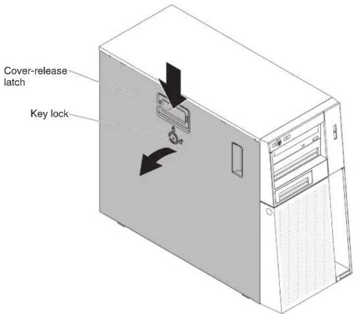
- If you are instructed to return the side cover, follow all packaging instructions, and use any packaging materials for shipping that are supplied to you.
Installing the side cover
Attention: For proper cooling and airflow, replace the side cover before turning on the server. Operating the server for extended periods of time (more than 30 minutes) with the side cover removed might damage server components.
For 4U server models with non-hot-swap power supplies, complete the following steps in order to remove the side cover. For the 5U server model with hot-swap power supplies (Model name: 2582-F4x), please see the next sub-section.
-
Make sure that all cables, adapters, and other components are installed and seated correctly and that you have not left loose tools or parts inside the server. Also, make sure that all internal cables are correctly routed.
-
Carefully turn the server on its side so that it is lying flat, with the cover facing up.
Attention: Do not allow the server to fall over.
- Press on the side cover and push from the rear side of the side cover until it locks securely into place.
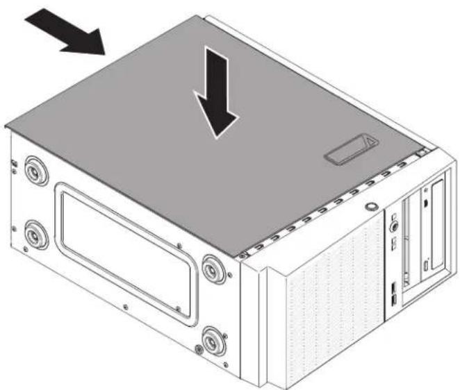
natural_image
Isometric line drawing of a computer tower case with a highlighted top panel and two arrows indicating downward motion (no text or symbols present)- Secure the side cover in place with the two chassis screws on the rear of the side cover.
- Reconnect the external cables and power cords; then, turn on the attached devices and turn on the server.
For the 5U server model with hot-swap power supplies (Model name: 2582-F4x), complete the following steps in order to remove the side cover. For 4U server models with non-hot-swap power supplies, please see the above sub-section.
- Make sure that all cables, adapters, and other components are installed and seated correctly and that you have not left loose tools or parts inside the server. Also, make sure that all internal cables are correctly routed.
Important: The cover lock must be in the unlocked (opened) position before you install the side cover.
-
If you removed the upper and lower bezels, reinstall them before you replace the side cover (see "Installing the upper bezel" on page 175 and "Installing the lower bezel" on page 173).
-
Position the lip at the bottom edge of the side cover on the ledge at the bottom of the chassis; then, rotate the cover up to the chassis. Press down on the cover release latch and push the cover into the chassis until it latches securely into place.
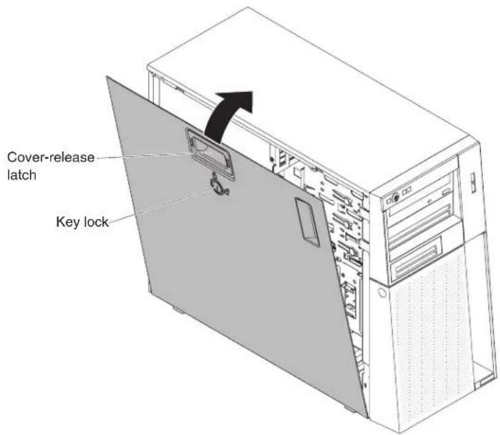
-
Lock the side cover.
-
Reconnect the external cables and power cords; then, turn on the attached devices and turn on the server.
Removing the bezel
This procedure applies only to 4U server models with non-hot-swap power supplies.
When you work with some devices on 4U server models with non-hot-swap power supplies, such as the drives in bays 3 through 6, you must first remove the bezel to access the devices.
To remove the bezel on 4U server models with non-hot-swap power supplies, complete the following steps.
-
Read the safety information that begins on page vi and "Installation guidelines" on page 163.
-
Open the bezel by pressing the button on the left edge of the bezel, and rotate the left side of the bezel away from the server.
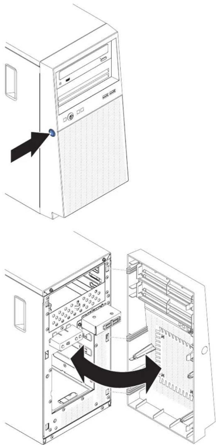
- If you are instructed to return the bezel, follow all packaging instructions, and use any packaging materials for shipping that are supplied to you.
Installing the bezel
This procedure applies only to 4U server models with non-hot-swap power supplies.
To install the bezel on 4U server models with non-hot-swap power supplies, complete the following steps.
- Insert the three tabs on the bezel into the corresponding holes in the front of the server.
- Rotate the bezel to the server until it locks securely into place.
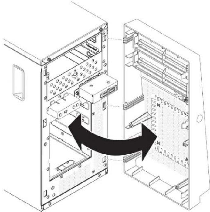
natural_image
Diagram of a computer tower internal structure showing internal components and an arrow indicating a process or transformation (no text or symbols present)- Reconnect the external cables and power cords; then, turn on the attached devices and turn on the server.
Removing the lower bezel
This procedure applies only to the 5U server model with hot-swap power supplies (Model name: 2582-F4x).
To access the hard disk drives on the 5U server model with hot-swap power supplies (Model name: 2582-F4x), you must first remove the lower bezel.
To remove the lower bezel on the 5U server model with hot-swap power supplies (Model name: 2582-F4x), complete the following steps.
-
Read the safety information that begins on page vii and "Installation guidelines" on page 163.
-
If you are replacing a non-hot-swap component, turn off the server and all attached devices; then, disconnect all power cords and external cables.
-
Press the blue-colored release button on the right side of the lower bezel and rotate the lower bezel downward to disengage from the chassis.
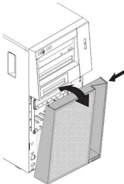
natural_image
Diagram of a computer tower with an open storage unit and directional arrows indicating movement (no text or symbols present)- If you are instructed to return the lower bezel, follow all packaging instructions, and use any packaging materials for shipping that are supplied to you.
Installing the lower bezel
This procedure applies only to the 5U server model with hot-swap power supplies (Model name: 2582-F4x).
To install the lower bezel on the 5U server model with hot-swap power supplies (Model name: 2582-F4x), complete the following steps.
- Insert the two bottom tabs on the lower bezel into the corresponding holes in the front of the chassis.

natural_image
Diagram of a computer tower with an open storage unit and directional arrows indicating movement or force (no text or symbols present)-
Rotate the top of the lower bezel up to the chassis; then, press the blue-colored release tab on the right side of the lower bezel and completely close the lower bezel until it locks securely into place.
-
Reconnect the external cables and power cords; then, turn on the attached devices and turn on the server.
Removing the upper bezel
This procedure applies only to the 5U server model with hot-swap power supplies (Model name: 2582-F4x).
To access the DVD drive or tape drive on the 5U server model with hot-swap power supplies (Model name: 2582-F4x), you must first remove the upper bezel to access the devices.
To remove the upper bezel on the 5U server model with hot-swap power supplies (Model name: 2582-F4x), complete the following steps.
- Read the safety information that begins on page vi and "Installation guidelines" on page 163.
- If you are replacing a non-hot-swap component, turn off the server and all attached devices; then, disconnect all power cords and external cables.
- Unlock and remove the side cover (see "Removing the side cover" on page 166).
- Remove the lower bezel (see "Removing the lower bezel" on page 171).
- Carefully pull the two bezel clips on the left side of the upper bezel; then, rotate the upper bezel to the right side of the server to disengage the two right-side tabs from the chassis.
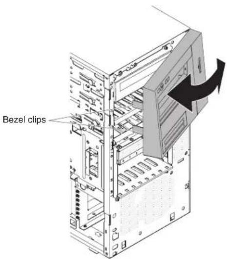
- If you are instructed to return the upper bezel, follow all packaging instructions, and use any packaging materials for shipping that are supplied to you.
Installing the upper bezel
This procedure applies only to the 5U server model with hot-swap power supplies (Model name: 2582-F4x).
To install the upper bezel on the 5U server model with hot-swap power supplies (Model name: 2582-F4x), complete the following steps.
- Insert the two tabs on the right-side of the upper bezel into the corresponding holes on the right side of the chassis.
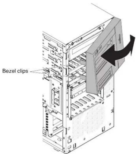
-
Rotate the upper bezel to the left side of the chassis until the bezel clips are aligned with the corresponding indentations on the left side of the chassis and snap them into place.
-
Install the lower bezel (see "Installing the lower bezel" on page 173).
-
Install and lock the side cover (see "Installing the side cover" on page 167).
-
Reconnect the external cables and power cords; then, turn on the attached devices and turn on the server.
Removing a ServeRAID adapter
To remove an ServeRAID adapter on 4U server models with non-hot-swap power supplies, complete the following steps. For the 5U server model with hot-swap power supplies (Model name: 2582-F4x), please see the next sub-section.
-
Read the safety information that begins on page via and "Installation guidelines" on page 163.
-
Turn off the server and all peripheral devices; then, disconnect the power cords and all external cables.
-
Carefully turn the server on its side so that it is lying flat, with the cover facing up.
Attention: Do not allow the server to fall over.
-
Remove the side cover (see "Removing the side cover" on page 166).
-
Remove the air duct.
-
Disconnect any cables from the ServeRAID adapter or any cables that impede access to the ServeRAID adapter.
-
Lift the end of the rear adapter retention bracket till the tab disengages the hole on the chassis.

natural_image
Technical diagram of a computer motherboard showing internal components and directional arrows (no text or labels)-
Rotate the rear adapter retention bracket upward to remove it from the chassis.
-
Remove the expansion-slot screw at the rear of the adapter if any.
-
Carefully grasp the adapter by its top edge or upper corners; then, pull the adapter to remove it from the server.
Attention: Expansion-slot covers must be installed in all empty slots. This maintains the electronic emissions standards of the computer and ensures proper ventilation of computer components.
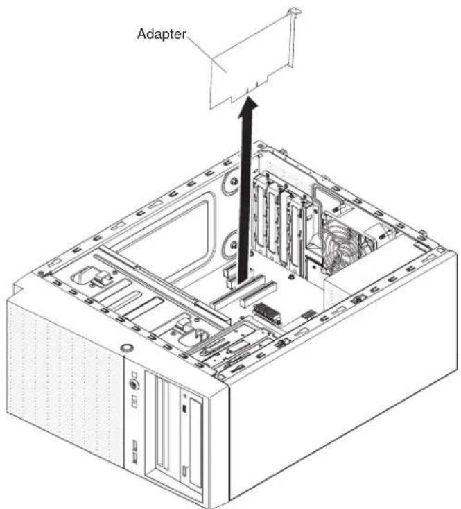
- If you are not replacing the adapter, install an expansion-slot cover in the expansion-slot opening.
- If you are instructed to return the adapter, follow all packaging instructions, and use any packaging materials for shipping that are supplied to you.
To remove an ServeRAID adapter on the 5U server model with hot-swap power supplies (Model name: 2582-F4x), complete the following steps. For 4U server models with non-hot-swap power supplies, please see the above sub-section.
- Read the safety information that begins on page 6 and "Installation guidelines" on page 163.
- Turn off the server and all attached devices; then, disconnect all power cords and external cables.
- Unlock and remove the side cover (see "Removing the side cover" on page 166).
- Carefully turn the server on its side so that it is lying flat, with the system board facing up.
Attention: Do not allow the server to fall over.
- Disconnect any cables from the adapter or any cables that impede access to the adapter.
- Rotate the rear adapter-retention bracket to the open (unlocked) position.
- Carefully grasp the adapter by its top edge or upper corners, and pull the adapter from the server.
Attention: Expansion-slot covers must be installed in all empty slots. This maintains the electronic emissions standards of the computer and ensures proper ventilation of computer components.

-
If you are not replacing the adapter, install an expansion-slot cover in the expansion-slot opening.
-
If you are instructed to return the adapter, follow all packaging instructions, and use any packaging materials for shipping that are supplied to you.
Installing a ServeRAID adapter
For information about the types of ServeRAID adapters that the server supports and other information that you might consider when you install an ServeRAID adapter, see the InstallationandUser'sGuide. (For the locations of the expansion slots and connectors, see 'System-board internal connectors' on page 17).
Note: If you are installing Intel Ethernet Quad Port Server Adapter I340-T4 (part number 49Y4240), you can only install the adaptor in slot 1, slot 2, or slot 3.
To install a replacement ServeRAID adapter on 4U server models with non-hot-swap power supplies, complete the following steps. For the 5U server model with hot-swap power supplies (Model name: 2582-F4x), please see the next sub-section.
- Read the safety information that begins on page vi and "Installation guidelines" on page 163.
- Check the instructions that come with the adapter for any requirements, restrictions, or cabling instructions. It might be easier to route cables before you install the adapter.
-
Follow the instructions that come with the adapter to set jumpers or switches, if any.
-
Touch the static-protective package that contains the adapter to any unpainted metal surface on the server. Then, remove the adapter from the static-protective package. Avoid touching the components and gold-edge connectors on the adapter.
-
Turn off the server and all peripheral devices; then, disconnect the power cords and all external cables.
-
Carefully turn the server on its side so that it is lying flat, with the cover facing up.
Attention: Do not allow the server to fall over.
-
Remove the side cover (see "Removing the side cover" on page 166).
-
Remove the air duct.
-
Follow the cabling instructions, if any, that come with the adapter. Route the adapter cables before you install the adapter.
-
Follow the instructions that come with the adapter to set jumpers or switches, if any.
-
Lift the end of the rear adapter retention bracket till the tab disengages the hole on the chassis.
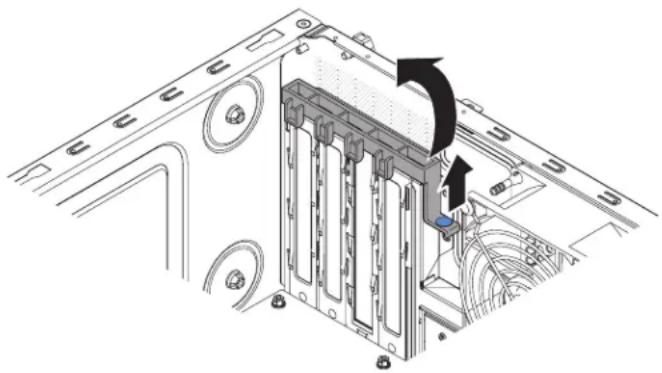
natural_image
Technical diagram of a computer tower internal structure with arrows indicating motion or assembly (no text or symbols present)-
Rotate the rear adapter retention bracket upward to remove it from the chassis.
-
Remove the screw that secures the expansion-slot cover to the chassis. Store the expansion-slot cover and screw in a safe place for future use.
Note: Expansion-slot covers must be installed on all vacant slots. This maintains the electronic emissions standards of the server and ensures proper ventilation of server components.
-
Touch the static-protective package that contains the adapter to any unpainted metal surface on the server. Then, remove the adapter from the static-protective package. Avoid touching the components and gold-edge connectors on the adapter.
-
Carefully grasp the adapter by the top edge or upper corners, and align it with the expansion slot guides; then, press the adapter firmly into the expansion slot.
Attention: Make sure that the adapter is correctly seated in the expansion slot before you turn on the server. Incomplete installation of an adapter might damage the system board or the adapter.

- Position the rear adapter retention bracket so that the hole in one of the hinge points is aligned with the hinge pin on the chassis; then, place the hinge pin through the hole on the chassis.

natural_image
Technical diagram of a computer motherboard showing internal components and a close-up inset of a component (no text or symbols)-
Rotate the rear adapter retention bracket into place so that the hole in the opposite hinge point snaps into place over the hinge pin on the chassis.
-
Connect any required cables to the adapter. Route the cables so that they do not block the flow of air from the system fan.
-
Install the air duct.
-
Install the side cover (see "Installing the side cover" on page 167).
-
Stand the server back up in its vertical position.
-
Install bezel (see "Installing the bezel" on page 1/1).
- Reconnect the external cables and power cords; then, turn on the attached devices and turn on the server.
Note: To support Windows 2011 SBS on Brocade adapters need to use at least 3.0.0.0 driver package or later version.
To install a replacement ServeRAID adapter on the 5U server model with hot-swap power supplies (Model name: 2582-F4x), complete the following steps. For 4U server models with non-hot-swap power supplies, please see the above sub-section.
- Read the safety information that begins on page vi and "Installation guidelines" on page 163.
- Check the instructions that come with the adapter for any requirements, restrictions, or cabling instructions. It might be easier to route cables before you install the adapter.
- Follow the instructions that come with the adapter to set jumpers or switches, if any.
- Touch the static-protective package that contains the adapter to any unpainted metal surface on the server. Then, remove the adapter from the static-protective package. Avoid touching the components and gold-edge connectors on the adapter.
- Turn off the server and all peripheral devices; then, disconnect the power cords and all external cables.
- Unlock and remove the side cover (see "Removing the side cover" on page 166).
- Carefully turn the server on its side so that it is lying flat, with the system board facing up.
Attention: Do not allow the server to fall over.
- Rotate the rear adapter-retention bracket to the open (unlocked) position.
- Carefully grasp the adapter by the top edge or upper corner, and move the adapter directly from the static-protective package to the expansion slot. Align the adapter with the expansion slot guides; then, press the adapter firmly into the expansion slot.
- Connect the required cables to the adapter. Route cables so that they do not block the air flow from the fan.
- Rotate the rear adapter-retention bracket to the closed (locked) position.

- Stand the server back up in its vertical position.
- Install and lock the side cover (see "Installing the side cover" on page 167).
- Reconnect the external cables and power cords; then, turn on the attached devices and turn on the server.
Removing and installing internal drives
The following figure shows the locations of the drive bays in 4U server models with non-hot-swap power supplies.
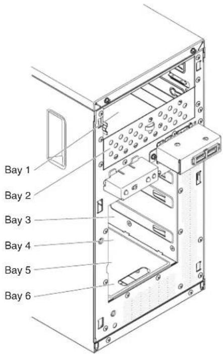
The following figure shows the locations of the drive bays in the 5U server model with hot-swap power supplies (Model name: 2582-F4x).
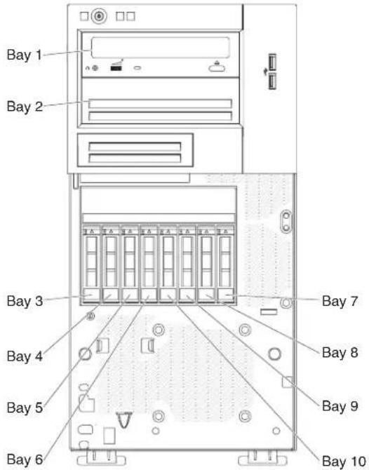
The following notes describe the types of drives that the server supports and other information that you must consider when installing a drive:
- Make sure that you have all the cables and other equipment that is specified in the documentation that comes with the drive.
- Check the instructions that come with the drive to see whether you have to set any switches or jumpers on the drive. If you are installing a SATA device, be sure to set the SATA ID for that device.
- Optional external tape drives, DVD-ROM drive are examples of removable-media drives. You can install removable-media drives only in bays 1 and 2.
•The electromagnetic interference (EMI) integrity and cooling of the server are protected by having all bays and PCI slots covered or occupied. When you install a drive or PCI adapter, save the EMC shield and filler panel from the bay or the PCI adapter slot cover in the event that you later remove the drive or adapter.
- For a complete list of supported options for the server, see http://www.ibm.com/servers/eserver/serverproven/compat/us/.
Removing a DVD drive
To remove a DVD drive in 4U server models with non-hot-swap power supplies, complete the following steps. For the 5U server model with hot-swap power supplies (Model name: 2582-F4x), please see the next sub-section.
-
Read the safety information that begins on page vi and "Installation guidelines" on page 163.
-
Turn off the server and all peripheral devices; then, disconnect the power cords and all external cables.
-
Remove the bezel (see "Removing the bezel" on page 169).
-
Carefully turn the server on its side so that it is lying flat, with the cover facing up.
Attention: Do not allow the server to fall over.
-
Remove the side cover (see "Removing the side cover" on page 166).
-
Disconnect the power cable and then the signal cables from the drive that is to be removed.
-
Stand the server back up in its vertical position.
-
Press and hold the blue release button on the side of the bay to release the drive; then, pull the drive out of the front of the server.
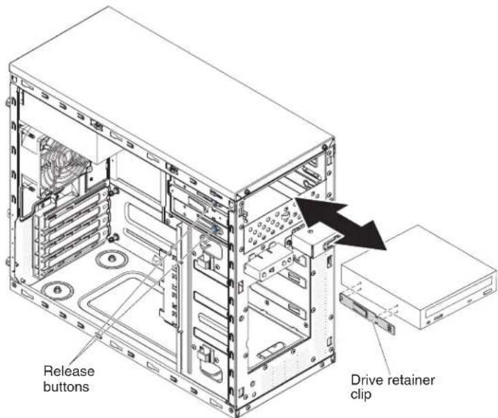
-
Remove the drive retainer clip from the side of the drive. Save the clip to use when you install the replacement drive.
-
If you are instructed to return the drive, follow all packaging instructions, and use any packaging materials for shipping that are supplied to you.
To remove a DVD drive in the 5U server model with hot-swap power supplies (Model name: 2582-F4x), complete the following steps. For 4U server models with non-hot-swap power supplies, please see the above sub-section.
- Read the safety information that begins on page vii and "Installation guidelines" on page 163.
- Turn off the server and all attached devices; then, disconnect all power cords and external cables.
- Unlock and remove the side cover (see "Removing the side cover" on page 166).
- Remove the lower bezel (see "Removing the lower bezel" on page 171).
- Remove the upper bezel (see "Removing the upper bezel" on page 174).
- Disconnect the power and signal cables from the drive that is to be removed.
- Press and hold the blue-colored release button on the side of the bay to release the drive; then, pull the drive out of the front of the server.
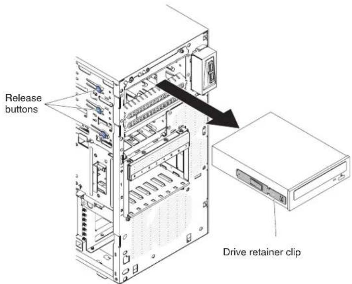
-
Remove the drive retainer clip from the side of the drive. Save the clip to use when you install the replacement drive.
-
If you are instructed to return the drive, follow all packaging instructions, and use any packaging materials for shipping that are supplied to you.
Installing a DVD drive
To install a DVD drive, complete the following steps.
If you are replacing a removed drive with a new drive, make sure that:
- You have all the cables and other equipment that is specified in the documentation that comes with the new drive.
- You have checked the instructions that come with the new drive to determine whether you must set any switches or jumpers in the drive.
- You have removed the blue optical drive retainer clip from the side of the old drive and have them available for installation on the new drive.
Note: If you are installing a drive that contains a laser, observe the following safety precaution.
Statement 3:

CAUTION:
When laser products (such as CD-ROMs, DVD drives, fiber optic devices, or transmitters) are installed, note the following:
- Do not remove the covers. Removing the covers of the laser product could result in exposure to hazardous laser radiation. There are no serviceable parts inside the device.
- Use of controls or adjustments or performance of procedures other than those specified herein might result in hazardous radiation exposure.

DANGER
Some laser products contain an embedded Class 3A or Class 3B laser diode. Note the following.
Laser radiation when open. Do not stare into the beam, do not view directly with optical instruments, and avoid direct exposure to the beam.

Class 1 Laser Product
Laser Klasse 1
Laser Klass 1
Luokan 1 Laserlaite
To install a DVD drive on 4U server models with non-hot-swap power supplies, complete the following steps. For the 5U server model with hot-swap power supplies (Model name: 2582-F4x), please see the next sub-section.
-
Read the safety information that begins on page vi and "Installation guidelines" on page 163.
-
Follow the instructions that come with the drive to set jumpers or switches, if there are any.
Note: You might find it easier to install the new drive from the front and then attach the cables.
-
Turn off the server and all peripheral devices; then, disconnect the power cords and all external cables.
-
Remove the bezel (see "Removing the bezel" on page 169).
-
Carefully turn the server on its side so that it is lying flat, with the cover facing up.
Attention: Do not allow the server to fall over.
-
Remove the side cover (see "Removing the side cover" on page 166).
-
Touch the static-protective package that contains the new DVD drive to any unpainted metal surface on the server; then, remove the DVD drive from the package and place it on a static-protective surface.
-
Stand the server back up in its vertical position.
-
Remove the drive retainer clip from the side of the drive cage of bay 1 or bay 2. Slide the drive retainer clip to the front to remove it from the drive cage; then, snap the drive retainer clip into the screw holes on the side of the drive.

-
Push the drive into the bay.
-
Carefully turn the server on its side so that it is lying flat.
Attention: Do not allow the server to fall over.
- Connect the power (power connector P9) and signal cables to the drive.
Note: Route the signal cable so that it does not block the airflow to the rear of the drives or over the microprocessor and dual inline memory modules (DIMMs).
-
If you have another drive to install or remove, do so now.
-
Install the side cover (see "Installing the side cover" on page 167).
-
Stand the server back up in its vertical position.
-
Install bezel (see "Installing the bezel" on page 171).
Note: Remove the filler blocking the installed drive if any.
- Reconnect the external cables and power cords; then, turn on the attached devices and turn on the server.
To install a DVD drive on the 5U server model with hot-swap power supplies (Model name: 2582-F4x), complete the following steps. For 4U server models with non-hot-swap power supplies, please see the above sub-section.
-
Touch the static-protective package that contains the new DVD drive to any unpainted metal surface on the server; then, remove the DVD drive from the package and place it on a static-protective surface.
-
Follow the instructions that come with the drive to set jumpers or switches, if there are any.
Note: You might find it easier to install the new drive from the front and then attach the cables.
-
Attach the drive retainer clip that you removed from the previous drive to the side of the new drive.
-
Push the drive into the bay.
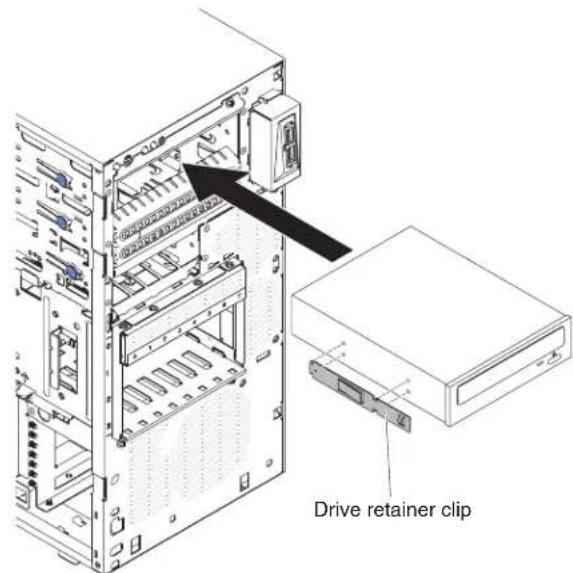
- Connect the power and signal cables to the drive.
Note: Route the signal cable so that it does not block the airflow to the rear of the drives or over the microprocessor and dual inline memory modules (DIMMs).
- Install the upper bezel (see "Installing the upper bezel" on page 175).
- Install the lower bezel (see "Installing the lower bezel" on page 173).
- Install and lock the side cover (see "Installing the side cover" on page 167).
- Reconnect the external cables and power cords; then, turn on the attached devices and turn on the server.
Removing a tape drive
To remove a tape drive on 4U server models with non-hot-swap power supplies, complete the following steps. For the 5U server model with hot-swap power supplies (Model name: 2582-F4x), please see the next sub-section.
- Read the safety information that begins on page via and "Installation guidelines" on page 163.
- Turn off the server and all peripheral devices; then, disconnect the power cords and all external cables.
- Remove the bezel (see "Removing the bezel" on page 169).
- Carefully turn the server on its side so that it is lying flat, with the cover facing up.
Attention: Do not allow the server to fall over.
-
Remove the side cover (see "Removing the side cover" on page 166).
-
Disconnect the power cable and then the signal cables from the drive that is to be removed.
- Stand the server back up in its vertical position.
- Press and hold the blue release button on the side of the bay to release the drive; then, pull the drive out of the front of the server.
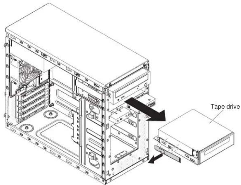
- Remove the drive retainer clip from the side of the drive. Save the clip to use when you install the replacement drive.
- If you are instructed to return the drive, follow all packaging instructions, and use any packaging materials for shipping that are supplied to you.
To remove a tape drive on the 5U server model with hot-swap power supplies (Model name: 2582-F4x), complete the following steps. For 4U server models with non-hot-swap power supplies, please see the above sub-section.
-
Read the safety information that begins on page vi and "Installation guidelines" on page 163.
-
Turn off the server and peripheral devices, and disconnect the power cords and all external cables.
-
Unlock and remove the side cover (see "Installing the side cover" on page 167).
-
Remove the lower bezel (see "Removing the lower bezel" on page 1/1).
-
Remove the upper bezel (see "Removing the upper bezel" on page 174).
-
Disconnect the power and signal cables from the drive that is to be removed.
-
Press and hold the blue release button on the side of the bay to release the drive; then, pull the drive out of the front of the server.
-
Remove the drive retainer clip from the side of the drive. Save the clip to use when you install the replacement drive.
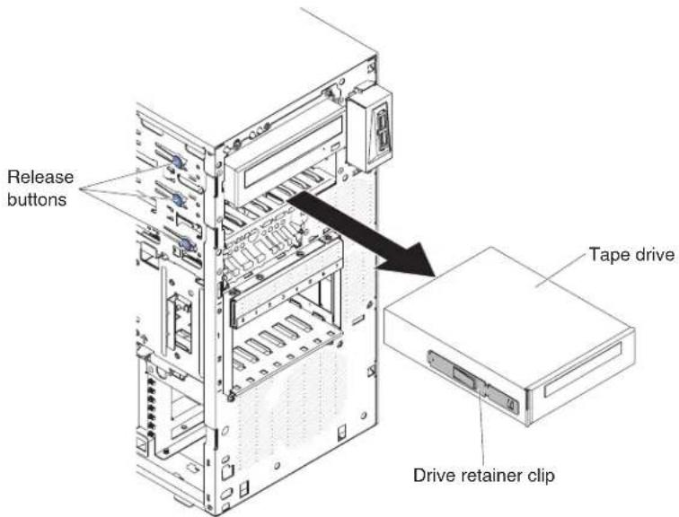
- If you are instructed to return the drive, follow all packaging instructions, and use any packaging materials for shipping that are supplied to you.
Installing a tape drive
If you are replacing a removed drive with a new drive, make sure that:
- You have all the cables and other equipment that is specified in the documentation that comes with the new drive.
- You check the instructions that come with the new drive to determine whether you must set any switches or jumpers on the drive.
- You have removed the drive retainer clip on the side of the old drive and have it available for installation on the new drive.
To install a tape drive on 4U server models with non-hot-swap power supplies, complete the following steps. For the 5U server model with hot-swap power supplies (Model name: 2582-F4x), please see the next sub-section.
- Read the safety information that begins on page vi and "Installation guidelines" on page 163.
- Turn off the server and peripheral devices, and disconnect the power cords and all external cables.
- Remove the bezel (see "Installing the bezel" on page 1/1).
- Carefully turn the server on its side so that it is lying flat, with the cover facing up.
Attention: Do not allow the server to fall over.
- Remove the side cover (see "Removing the side cover" on page 166).
- Remove the air duct.
- Touch the static-protective package that contains the drive to any unpainted metal surface on the server; then, remove the drive from the package and place it on a static-protective surface.
- Set any jumpers or switches on the drive according to the documentation that comes with the drive.
-
Stand the server back up in its vertical position.
-
Remove the drive retainer clip from the side of the drive cage of bay 1 or bay 2. Slide the drive retainer clip to the front to remove it from the drive cage; then, snap the drive retainer clip into the screw holes on the side of the drive.

- Remove the EMC filler.

natural_image
Technical line drawing of a computer tower internal structure with a black arrow indicating a component (no text or symbols present)Note: Be careful of any sharp edges.
- Push the drive into the bay.
Note: A tape drive can only be installed in bay 1 or bay 2
- Carefully turn the server on its side so that it is lying flat, with the cover facing up.
Attention: Do not allow the server to fall over.
-
Connect one end of the applicable signal cable into the rear of the drive and make sure that the other end of this cable is connected into the applicable connector on the system board.
-
Route the signal cable so that it does not block the airflow to the rear of the drives or over the microprocessor and dual inline memory modules (DIMMs).
-
If you have another drive to install or remove, do so now.
-
Install the air duct.
-
Install the side cover (see "Installing the side cover" on page 167).
-
Stand the server back up in its vertical position.
-
Install bezel (see "Installing the bezel" on page 171).
Note: Remove the bezel filler blocking the installed drive if any.

- Reconnect the external cables and power cords; then, turn on the attached devices and turn on the server.
To install a tape drive on the 5U server model with hot-swap power supplies (Model name: 2582-F4x), complete the following steps. For 4U server models with non-hot-swap power supplies, please see the above sub-section.
- Read the safety information that begins on page via and "Installation guidelines" on page 163.
- Turn off the server and peripheral devices, and disconnect the power cords and all external cables.
-
Unlock and remove the side cover (see "Removing the side cover" on page 166).
-
Remove the lower bezel (see "Removing the lower bezel" on page 1/1).
-
Remove the upper bezel (see "Removing the upper bezel" on page 174).
-
Touch the static-protective package that contains the drive to any unpainted metal surface on the server; then, remove the drive from the package and place it on a static-protective surface.
-
Set any jumpers or switches on the drive according to the documentation that comes with the drive.
-
Slide the drive retainer clip to the front to remove it from the drive cage of bay 2; then, snap the drive retainer clip into the screw holes on the side of the drive.

-
Remove the EMC filler.
-
Push the drive into the bay.
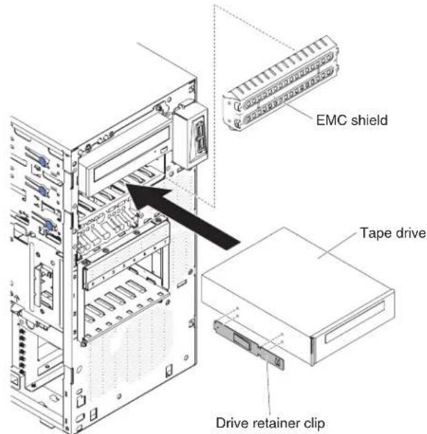
- Connect one end of the applicable signal cable into the rear of the drive and make sure that the other end of this cable is connected into the applicable connector on the system board.
- Route the signal cable so that it does not block the airflow to the rear of the drives or over the microprocessor and dual inline memory modules (DIMMs).
- Connect the power cable to the rear of the drive. The connectors are keyed and can be inserted only one way.
- Install the upper bezel (see "Installing the upper bezel" on page 175).
- Install the lower bezel (see "Installing the lower bezel" on page 173).
- Install and lock the side cover (see "Installing the side cover" on page 167).
- Reconnect the external cables and power cords; then, turn on the attached devices and turn on the server.
Removing a simple-swap hard disk drive
This procedure applies only to 4U server models with non-hot-swap power supplies.
Attention: Simple-swap hard disk drives are not hot-swappable. Disconnect all power from the server before you remove or install a simple-swap hard disk drive.
To remove a simple-swap SATA hard disk drive on 4U server models that have non-hot-swap power supplies, complete the following steps.
- Read the safety information that begins on page vi and "Installation guidelines" on page 163.
- Turn off the server and all attached devices; then, disconnect all power cords and external cables.
- Remove the bezel (see "Removing the bezel" on page 169).
- Pull the round blue loops of the drive assembly that is to be removed toward each other; then, pull the assembly out of the bay.

natural_image
Technical diagram of a server rack with internal components and a blue cable attachment (no text or symbols)- If you are instructed to return the drive assembly, follow all packaging instructions, and use any packaging materials for shipping that are supplied to you.
Installing a simple-swap hard disk drive
This procedure applies only to 4U server models with non-hot-swap power supplies.
For 4U server models with non-hot-swap power supplies, the server supports up to four 3.5-inch simple-swap SATA hard disk drives, which are accessible from the front of the server. You must disconnect all power from the server before you remove or install simple-swap drives. Before you install a simple-swap SATA hard disk drive, read the following information:
To install a simple-swap SATA hard disk drive on 4U server models with non-hot-swap power supplies, complete the following steps.
• Install the drives starting from the top bay to the bottom bay (bay 3, 4, 5, and then 6). The following tables list the IDs of the hard disk drives:
Table11.IDsofsimple-swapdrives
| Drive bay HDD ID | |
| 3 | 0 |
| 4 | 1 |
| 5 | 2 |
| 6 | 3 |
- The simple-swap SATA hard disk drives connect to the SATA 0 through SATA 3 connectors on the system board as follows:
– System board end cable connector 0 connects to the SATA 0 connector on the system board.
- System board end cable connector 1 connects to the SATA 1 connector on the system board.
– System board end cable connector 2 connects to the SATA 2 connector on the system board.
- System board end cable connector 3 connects to the SATA 3 connector on the system board.
.
– Hard disk drive 0 connects to the SATA 0 connector on the system board.
- Hard disk drive 1 connects to the SATA 2 connector on the system board.
- Hard disk drive 2 connects to the SATA 1 connector on the system board.
– Hard disk drive 3 connects to the SATA 3 connector on the system board.
Note: Under RAID mode:
-
In uEFI setup menu:
-
Drive 0 indicates hard disk drive 0.
- Drive 1 indicates hard disk drive 2.
- Drive 2 indicates hard disk drive 1.
-
Drive 3 indicates hard disk drive 3.
-
In MegaRAID Storage Manager utility:
-
Slot 0 indicates hard disk drive 0.
- Slot 1 indicates hard disk drive 2.
- Slot 2 indicates hard disk drive 1.
- Slot 3 indicates hard disk drive 3.
Attention: Simple-swap hard disk drives are not hot-swappable. Disconnect all power from the server before you remove or install a simple-swap hard disk drive.
Note: If you installed a ServeRAID adapter in the server, connect the other end of the SATA signal cable to the connector on the ServeRAID adapter.
To install a simple-swap SATA hard disk drive, complete the following steps.
-
Read the safety information that begins on page vi and "Installation guidelines" on page 163.
-
Turn off the server and peripheral devices and disconnect all external cables and power cords.
-
Remove the bezel (see "Removing the bezel" on page 169).
-
Touch the static-protective package that contains the drive to any unpainted metal surface on the server; then, remove the drive from the package and place it on a static-protective surface.
-
Align the drive assembly with the guide rails in the bay (the connector end of the drive goes in first).
-
Pull the round blue loops of the drive assembly toward each other; then, carefully slide the drive assembly into the drive bay until it stops, and release the loops.
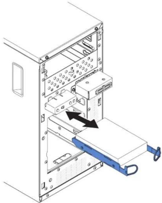
natural_image
Technical diagram of a server rack with an attached blue folder and black arrow indicating direction (no text or symbols present)Note: Do not release the loops on the drive assembly until it is completely seated.
-
If you have another drive to install or remove, do so now.
-
Install bezel (see "Installing the bezel" on page 171).
-
Reconnect the external cables and power cords; then, turn on the attached devices and turn on the server.
Table12.3TBHDDOSsupportlist
| OS Support limitation Support status | ||
| Windows 2008R2 SP1 64bit uEFI | Support | |
| Windows 2008R2 SP1 64bit legacy | Support with disk partitions less than 2 TB | Support with limitation |
| Windows 2008 SP2 64bit uEFI | Support | |
| Windows 2008 SP2 64bit legacy | Support with disk partitions less than 2 TB | Support with limitation |
| Windows 2008 SP2 32bit legacy | Support with disk partitions less than 2 TB | Support with limitation |
| RHEL 6.1 64bit uEFI Support | ||
| RHEL 6.1 64bit legacy Support | ||
| RHEL 6.1 32bit legacy Support | ||
| RHEL 5.6 64bit legacy RHEL 5.6 32bit legacy | Do not support, partition not allowed | Do not support |
| RHEL 5.6 64bit legacy RHEL 5.6 32bit legacy | Do not support, partition not allowed | Do not support |
| SLES11 SP1 64bit uEFI Support | ||
| SLES11 SP1 64bit legacy Support | ||
| SLES11 SP1 32bit legacy Support | ||
| SLES10 SP4 64bit legacy Support with disk partitions less than 2 TB | Support with limitation | |
| SLES10 SP4 32bit legacy Support with disk partitions less than 2 TB | Support with limitation | |
Note: 3TB hard disk drives are not supported in OS 4690.
Table13. ServeRAIDsupportlimitationon3TBHDD
| ServeRAID adapter Support limitation Comment | ||
| ServeRAID M5014 Support 3TB HDD, Virtual disk supports up to 12TB | Support | |
| ServeRAID M1015 Support 3TB HDD, Virtual disk supports up to 12TB | Support | |
| ServeRAID-BR10il Virtual disk only supports up to 8TB. | LSI chip limitation. Support with limitation. | |
| ServeRAID H1110 | Support 3TB HDD, Virtual disk supports up to 12TB | Support |
| ServeRAID C100 | Support 3TB HDD, Virtual disk supports up to 12TB | Support |
Removing a hot-swap hard disk drive
This procedure applies only to the 5U server model with hot-swap power supplies (Model name: 2582-F4x).
To remove a hot-swap hard disk drive on the 5U server model with hot-swap power supplies (Model name: 2582-F4x), complete the following steps.
Attention: To maintain proper system cooling, do not operate the server for more than 10 minutes without either a drive or a filler panel installed in each drive bay.
- Read the safety information that begins on page vii and "Installation guidelines" on page 163.
Note: You do not have to turn off the server to remove hot-swap drives from the hot-swap drive bays.
-
Remove the lower bezel (see "Removing the lower bezel" on page 171).
-
Rotate the drive tray handle of the drive assembly that is to be removed to the open position.
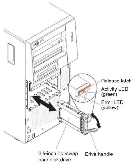
-
Grasp the handle of the drive assembly that is to be replaced and pull the assembly out of the bay.
-
If you are instructed to return the drive assembly, follow all packaging instructions, and use any packaging materials for shipping that are supplied to you.
Installing a hot-swap hard disk drive
This procedure applies only to the 5U server model with hot-swap power supplies (Model name: 2582-F4x).
Before you install a hot-swap hard disk drive, read the following information:
- The hot-swap drives must be either all SAS hard disk drives or all SATA hard disk drives; the two types cannot be combined.
- Inspect the drive tray for signs of damage.
•To maintain proper system cooling, do not operate the server for more than 10 minutes without either a drive or a filler panel installed in each drive bay.
- You do not have to turn off the server to install hot-swap drives in the hot-swap drive bays.
• See the Installation and User's Guide for additional information.
To install a hot-swap hard disk drive on the 5U server model that have hot-swap power supplies (Model name: 2582-F4x), complete the following steps.

- Touch the static-protective package that contains the drive to any unpainted metal surface on the server; then, remove the drive from the package and place it on a static-protective surface.
- Make sure that the drive tray handle is in the open position.
- Align the drive assembly with the guide rails in the bay; then, carefully slide the drive assembly into the drive bay until the drive stops.
- Rotate the drive tray handle to the closed position.
- Check the hard disk drive status indicator to make sure that the hard disk drive is operating correctly. (You might have to restart the server for the drive to be recognized.) If the yellow hard disk drive status LED for a drive is lit continuously, it indicates that the drive is faulty and must be replaced. If the green hard disk drive activity LED is flashing, this indicates that the drive is being accessed.
Note: If the server is configured for RAID operation using a ServeRAID controller, you might have to reconfigure the disk arrays after you replace hard disk drives. See the ServeRAID documentation for additional information about RAID operation and complete instructions for using ServeRAID Manager.
-
Install the lower bezel (see "Installing the lower bezel" on page 173).
-
Install and lock the side cover (see "Installing the side cover" on page 167).
Removing a memory module
To remove a dual inline memory module (DIMM) on 4U server models with non-hot-swap power supplies, complete the following steps. For the 5U server model with hot-swap power supplies (Model name: 2582-F4x), please see the next sub-section.
-
Read the safety information that begins on page vi and "Installation guidelines" on page 163.
-
Turn off the server and all attached devices; then, disconnect all power cords.
- Carefully turn the server on its side so that it is lying flat, with the cover facing up.
Attention: Do not allow the server to fall over.
- Remove the side cover (see "Removing the side cover" on page 166).
- Remove the air duct.
- Locate the DIMM connector that contains the DIMM that is to be replaced (see "System-board internal connectors" on page 17).
Attention: To avoid breaking the DIMM retaining clips or damaging the DIMM connectors, open and close the clips gently.
- Carefully open the retaining clips on each end of the DIMM connector and remove the DIMM.
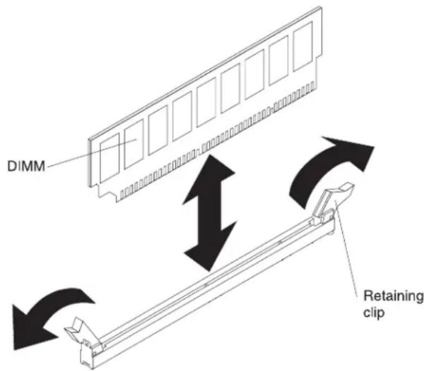
- If you are instructed to return the DIMM, follow all packaging instructions, and use any packaging materials for shipping that are supplied to you.
To remove a dual inline memory module (DIMM) on the 5U server model with hot-swap power supplies (Model name: 2582-F4x), complete the following steps. For 4U server models with non-hot-swap power supplies, please see the above sub-section.
- Read the safety information that begins on page vi and "Installation guidelines" on page 163.
- Turn off the server and all attached devices; then, disconnect all power cords.
- Unlock and remove the side cover (see "Removing the side cover" on page 166).
- Carefully turn the server on its side so that it is lying flat, with the system board facing up.
Attention: Do not allow the server to fall over.
- Locate the DIMM connector that contains the DIMM that is to be replaced (see "System-board internal connectors" on page 17).
Attention: To avoid breaking the DIMM retaining clips or damaging the DIMM connectors, open and close the clips gently.
- Carefully open the retaining clips on each end of the DIMM connector and remove the DIMM.
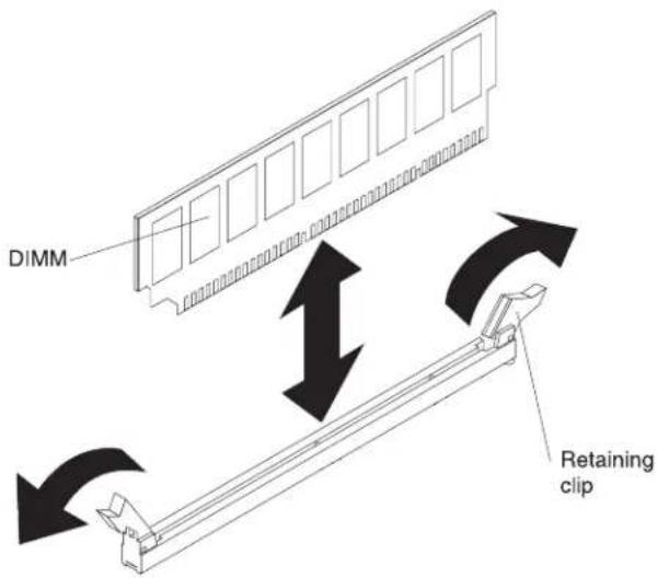
- If you are instructed to return the DIMM, follow all packaging instructions, and use any packaging materials for shipping that are supplied to you.
Installing a memory module
The following notes describe the types of dual inline memory modules (DIMMs) that the server supports and other information that you must consider when you install DIMMs (see "System-board internal connectors" on page 17).
•The server supports industry-standard, 1066, 1333 and 1600 MHz, PC3-12800 (single-rank or dual-rank) double-data-rate 3 (DDR3), registered or unbuffered, synchronous dynamic random-access memory (SDRAM) dual inline memory modules (DIMMs) with error correcting code (ECC). For a list of supported options for the server, see http://www.ibm.com/servers/eserver/serverproven/compat/us; then, select your country and navigate to the list of options for the server.
- The maximum amount of memory that the server supports is dependent on the type of memory that you install in the server.
- The amount of usable memory is reduced, depending on the system configuration. A certain amount of memory must be reserved for system resources. To view the total amount of installed memory and the amount of configured memory, run the Setup utility. For additional information, see "Using the Setup utility" on page 271.
- The maximum operating speed of the server is determined by the slowest DIMM in the server.
- If you install a pair of DIMMs in DIMM connectors 1 and 3, the size and speed of the DIMMs that you install in DIMM connectors 1 and 3 must match each other. However, they do not have to be the same size and speed as the DIMMs that are installed in DIMM connectors 2 and 4.
- You can use compatible DIMMs from various manufacturers in the same pair.
- When you install or remove DIMMs, the server configuration information changes. When you restart the server, the system displays a message that indicates that the memory configuration has changed.
Attention: Static electricity that is released to internal server components when the server is powered-on might cause the server to stop, which could result in the loss of data. To avoid this potential problem, always use an electrostatic-discharge wrist strap or other grounding system when working inside the server with the power on.
•The specifications of a DDR3 DIMM are on a label on the DIMM, in the following format.
ggg eRxff-PC3-wwwwww-m-aa-bb-cc
where:
gggis the total capacity of the DIMM (for example, 1GB, 2GB, or 4GB)
eis the number of ranks
1 = single-rank
2 = dual-rank
4 = quad-rank
ffis the device organization (bit width)
4 = x4 organization (4 DQ lines per SDRAM)
8 = x8 organization
16 = x16 organization
wwwwis the DIMM bandwidth, in MBps
8500 = 8.53 GBps (PC3-1066 SDRAMs, 8-byte primary data bus)
10600 = 10.66 GBps (PC3-1333 SDRAMs, 8-byte primary data bus)
12800 = 12.8 GBps (PC3-1600 SDRAMs, 8-byte primary data bus) mis the DIMM type
E = Unbuffered DIMM (UDIMM) with ECC (x72-bit module data bus)
R = Registered DIMM (RDIMM)
U = Unbuffered DIMM with no ECC (x64-bit primary data bus) aais the CAS latency, in clocks at maximum operating frequency bbis the JEDEC SPD Revision Encoding and Additions level ccis the reference design file for the design of the DIMM dis the revision number of the reference design of the DIMM
Note: To determine the type of a DIMM, see the label on the DIMM. The information on the label is in the format xxxxx nRxxx PC3-xxxxx-xx-xx-xxx. The numeral in the sixth numerical position indicates whether the DIMM is single-rank (n=1) or dual-rank (n=2).
Unbuffered DIMMs (UDIMMs)
The following notes provide information that you must consider when you install UDIMMs:
- The memory channels run at the lowest common frequency of the DIMMs installed.
- The UDIMM options that are available for the server are 1 GB, 2 GB, 4 GB, and 8 GB (when available) DIMMs.
•The server supports up to two single-rank or dual-rank UDIMMs per channel.
•The following table lists the supported UDIMM population.
Table14. SupportedUDIMMpopulationperchannel
| DIMM connectors per channel | DIMMs installed in each channel | DIMM type DIMM speed | Ranks per DIMM (any combination) | |
| 2 1 Unbuffered | DDR3 ECC | 1066, 1333, 1600 | Single-rank, dual-rank | |
| 2 2 Unbuffered | DDR3 ECC | 1066, 1333, 1600 | Single-rank, dual-rank | |
•The following table lists the maximum DIMM population using ranked UDIMMs.
Table15.MaximummemorypopulationusingrankedUDIMMs(dependingonyourmodel)
| Number of UDIMMs DIMM type Size Total memory | |||
| 4 Single-rank UDIMMs | 1 GB | 4 GB | |
| 4 Dual-rank UDIMMs | 2 GB | 8 GB | |
| 4 Dual-rank UDIMMs | 4 GB | 16 GB | |
| 4 Dual-rank UDIMMs | 8 GB (when available) | 32 GB | |
- The following table shows the UDIMM memory population rule to optimize the system performance.
Table16.UDIMMpopulationrule
| DIMM connector 1 | DIMM connector 2 | DIMM connector 3 | DIMM connector 4 |
| Populated | Empty | Empty | Empty |
| DIMM connector 1 DIMM connector 2 DIMM | connector 3 DIMM connector 4 | ||
| Populated Empty Populated Empty | |||
| Populated Populated Populated Populated | |||
The following illustration shows the location of the DIMM connectors on the system board.
Note: The illustrations in this document might differ slightly from your model.
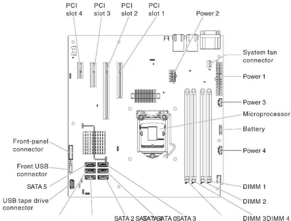
Attention: Static electricity that is released to internal server components when the server is powered on might cause the server to halt, which might result in the loss of data. To avoid this potential problem, always use an electrostatic-discharge wrist strap or other grounding system when you work inside the server with the power on.
To install a DIMM on 4U server models with non-hot-swap power supplies, complete the following steps. For the 5U server model with hot-swap power supplies (Model name: 2582-F4x), please see the next sub-section.
- Read the safety information that begins on page vii and "installation guidelines" on page 163.
- Turn off the server and peripheral devices, and disconnect the power cords and all external cables.
- Carefully turn the server on its side so that it is lying flat, with the cover facing up.
Attention: Do not allow the server to fall over. - Remove the side cover (see "Removing the side cover" on page 166).
-
Remove the air duct.
-
Locate the DIMM connectors on the system board. Determine the connectors into which you will install the DIMMs. Install the DIMMs in the sequence shown in the following table.
Table17.DIMMinstallationsequence
| Number of DIMMs Installation sequence (connectors) | |
| First pair of DIMMs 1, 3 | |
| Second pair of DIMMs 2, 4 | |
- Open the retaining clips and, if necessary, remove any existing DIMM.
Attention: To avoid breaking the retaining clips or damaging the DIMM connectors, open and close the clips gently.
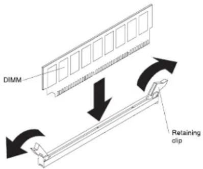
- Touch the static-protective package that contains the DIMM to any unpainted metal surface on the outside of the server. Then, remove the DIMM from the package.
- Turn the DIMM so that the DIMM keys align correctly with the connector.
- Insert the DIMM into the connector by aligning the edges of the DIMM with the slots at the ends of the DIMM connector.
- Firmly press the DIMM straight down into the connector by applying pressure on both ends of the DIMM simultaneously. The retaining clips snap into the locked position when the DIMM is firmly seated in the connector.
Note: If there is a gap between the DIMM and the retaining clips, the DIMM has not been correctly inserted; open the retaining clips, remove the DIMM, and then reinsert it.
-
Install the air duct.
-
Install the side cover (see "Installing the side cover" on page 167).
-
Stand the server back up in its vertical position.
-
Install bezel (see "Installing the bezel" on page 171).
-
Reconnect the external cables and power cords; then, turn on the attached devices and turn on the server.
To install a DIMM on the 5U server model with hot-swap power supplies (Model name: 2582-F4x), complete the following steps. For 4U server models with non-hot-swap power supplies, please see the above sub-section.
- Read the safety information that begins on page vii and "Installation guidelines" on page 163.
-
Turn off the server and peripheral devices, and disconnect the power cords and all external cables.
-
Unlock and remove the side cover (see "Removing the side cover" on page 166).
-
Carefully turn the server on its side so that it is lying flat, with the system board facing up.
Attention: Do not allow the server to fall over.
- Locate the DIMM connectors on the system board. Determine the connectors into which you will install the DIMMs. Install the DIMMs in the sequence shown in the following table.
Table18.DIMMinstallationsequence
| Number of DIMMs Installation sequence (connectors) | |
| First pair of DIMMs 1, 3 | |
| Second pair of DIMMs 2, 4 | |
- Open the retaining clips and, if necessary, remove any existing DIMM.
Attention: To avoid breaking the retaining clips or damaging the DIMM connectors, open and close the clips gently.
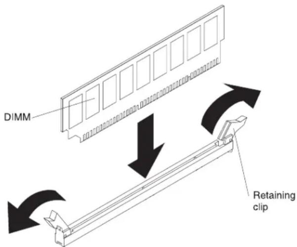
-
Touch the static-protective package that contains the DIMM to any unpainted metal surface on the server. Then, remove the new DIMM from the package.
-
Turn the DIMM so that the DIMM keys align correctly with the connector.
-
Insert the DIMM into the connector by aligning the edges of the DIMM with the slots at the ends of the DIMM connector. Firmly press the DIMM straight down into the connector by applying pressure on both ends of the DIMM simultaneously. The retaining clips snap into the locked position when the DIMM is firmly seated in the connector. If there is a gap between the DIMM and the retaining clips, the DIMM has not been correctly installed. Open the retaining clips, remove the DIMM, and then reinsert it.
-
Install and lock the side cover (see "Installing the side cover" on page 167).
-
Stand the server back up in its vertical position.
-
Reconnect the external cables and power cords; then, turn on the attached devices and turn on the server.
Removing the system battery
The following notes describe information that you must consider when you replace the battery:
- IBM has designed this product with your safety in mind. The lithium battery must be handled correctly to avoid possible danger. If you replace the battery, you must adhere to the following instructions.
Note: In the U. S., call 1-800-IBM-4333 for information about battery disposal.
- If you replace the original lithium battery with a heavy-metal battery or a battery with heavy-metal components, be aware of the following environmental consideration. Batteries and accumulators that contain heavy metals must not be disposed of with normal domestic waste. They will be taken back free of charge by the manufacturer, distributor, or representative, to be recycled or disposed of in a proper manner.
•To order replacement batteries, call 1-800-IBM-SERV within the United States, and 1-800-465-7999 or 1-800-465-6666 within Canada. Outside the U.S. and Canada, call your support center or business partner.
Notes:
-
After you replace the battery, you must reconfigure the server and reset the system date and time.
-
You need to use IPMI to reset SEL Time, see http://publib.boulder.ibm.com/infocenter/Inxinfo/v3r0m0/index.jsp?topic=/liaai/ipmi/ipmikick.htm for more information.
Statement 2:

CAUTION:
When replacing the lithium battery, use only IBM Part Number 33F8354 or an equivalent type battery recommended by the manufacturer. If your system has a module containing a lithium battery, replace it only with the same module type made by the same manufacturer. The battery contains lithium and can explode if not properly used, handled, or disposed of.
Donot:
- Throw or immerse into water
- Heat to more than 100°C (212°F)
- Repair or disassemble
Dispose of the battery as required by local ordinances or regulations.
To remove the battery on 4U server models with non-hot-swap power supplies, complete the following steps. For the 5U server model with hot-swap power supplies (Model name: 2582-F4x), please see the next sub-section.
- Read the safety information that begins on page vi and "Installation guidelines" on page 163.
- Turn off the server and all attached devices; then, disconnect all power cords and external cables.
- Carefully turn the server on its side so that it is lying flat, with the cover facing up.
Attention: Do not allow the server to fall over.
- Remove the side cover (see "Removing the side cover" on page 166).
-
Remove the air duct.
-
Locate the battery on the system board (see "System-board internal connectors" on page 1/).
-
Remove the battery:
a. Use one finger to tilt the battery horizontally out of its socket, pushing it away from the socket.
b. Lift and remove the battery from the socket.
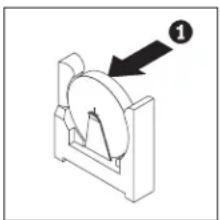
natural_image
Mechanical component diagram showing a circular disc mounted on a base, with an arrow pointing to it (no text or symbols present)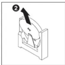
natural_image
Diagram of a mechanical component with an arrow indicating direction (no text or symbols)To remove the battery on the 5U server models with hot-swap power supplies (Model name: 2582-F4x), complete the following steps. For 4U server models with non-hot-swap power supplies, please see the above sub-section.
- Read the safety information that begins on page vi and "Installation guidelines" on page 163.
- Turn off the server and all attached devices; then, disconnect all power cords and external cables.
- Unlock and remove the side cover (see "Removing the side cover" on page 166).
- Carefully turn the server on its side so that it is lying flat, with the system board facing up.
Attention: Do not allow the server to fall over.
-
Locate the battery on the system board (see "System-board internal connectors" on page 17).
-
Remove the battery:
a. Use one finger to tilt the battery horizontally out of its socket, pushing it away from the socket.
b. Lift and remove the battery from the socket.
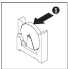
natural_image
Mechanical component diagram showing a circular component with an arrow pointing to it, labeled with number 1 (no text or symbols on the object itself)
natural_image
Isometric diagram of a mechanical component with an arrow indicating direction (no text or symbols)Installing the system battery
The following notes describe information that you must consider when you replace the battery in the server.
- You must replace the battery with a lithium battery of the same type from the same manufacturer.
•To order replacement batteries, call 1-800-426-7378 within the United States, and 1-800-465-7999 or 1-800-465-6666 within Canada. Outside the U.S. and Canada, call your IBM marketing representative or authorized reseller.
• After you replace the battery, you must reconfigure the server and reset the system date and time.
• To avoid possible danger, read and follow the following safety statement.
Statement 2:

CAUTION:
When replacing the lithium battery, use only IBM Part Number 33F8354 or an equivalent type battery recommended by the manufacturer. If your system has a module containing a lithium battery, replace it only with the same module type made by the same manufacturer. The battery contains lithium and can explode if not properly used, handled, or disposed of.
Donot:
- Throw or immerse into water
• Heat to more than 100°C (212°F)
•Repair or disassemble
Dispose of the battery as required by local ordinances or regulations.
To install the replacement battery on 4U server models with non-hot-swap power supplies, complete the following steps. For the 5U server model with hot-swap power supplies (Model name: 2582-F4x), please see the next sub-section.
- Follow any special handling and installation instructions that come with the replacement battery.
- Insert the battery:
a. Hold the battery in a vertical orientation so that the smaller side is facing the socket.
b. Tilt the battery and slide the battery into its socket; then, press the battery toward the socket until it clicks into place. Make sure that the battery clip holds the battery securely.
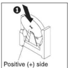

natural_image
Pure mechanical diagram showing a rotating component with an arrow indicating direction (no text or symbols)- Install the air duct.
- Install the side cover (see "Installing the side cover" on page 167).
- Stand the server back up in its vertical position.
- Reconnect the external cables and power cords; then, turn on the attached devices and turn on the server.
-
Start the Configuration/Setup Utility program and reset the configuration:
-
Set the system date and time.
- Set the power-on password.
•Reconfigure the server.
See "Using the Setup utility" on page 271 for details.
To install the replacement battery on the 5U server model with hot-swap power supplies (Model name: 2582-F4x), complete the following steps. For 4U server models with non-hot-swap power supplies, please see the above sub-section.
-
Follow any special handling and installation instructions that come with the replacement battery.
-
Insert the new battery:
a. Orient the battery so that the positive side faces up.
b. Tilt the battery and slide the battery into its socket
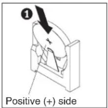
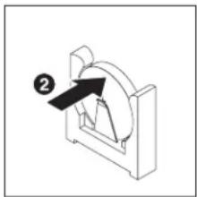
natural_image
Mechanical component diagram showing a curved bracket with an arrow and label (no text or symbols present)c. Press the battery down into the socket until it clicks into place. Make sure that the battery clip holds the battery securely.
- Stand the server back up in its vertical position.
- Install and lock the side cover (see "Installing the side cover" on page 167).
- Reconnect the external cables and power cords; then, turn on the attached devices and turn on the server.
-
Start the Configuration/Setup Utility program and reset the configuration:
-
Set the system date and time.
- Set the power-on password.
•Reconfigure the server.
See "Using the Setup utility" on page 271 for details.
Removing the rear system fan
This procedure applies only to 4U server models with non-hot-swap power supplies.
Attention:
•To ensure proper cooling and airflow, do not operate the server for more than 30 minutes with the side cover removed.
To remove the rear system fan on server models with non-hot-swap power supplies (4U chassis), complete the following steps.
- Turn off the server and all attached devices; then, disconnect all power cords and external cables.
- Carefully turn the server on its side so that it is lying flat, with the cover facing up.
Attention: Do not allow the server to fall over.
- Remove the side cover (see "Removing the side cover" on page 166).
- Remove the air duct.
- Remove any adapters that impede access to the fan and the fan connector on the system board (see "Removing a ServeRAID adapter" on page 176).
- Remove the system fan:
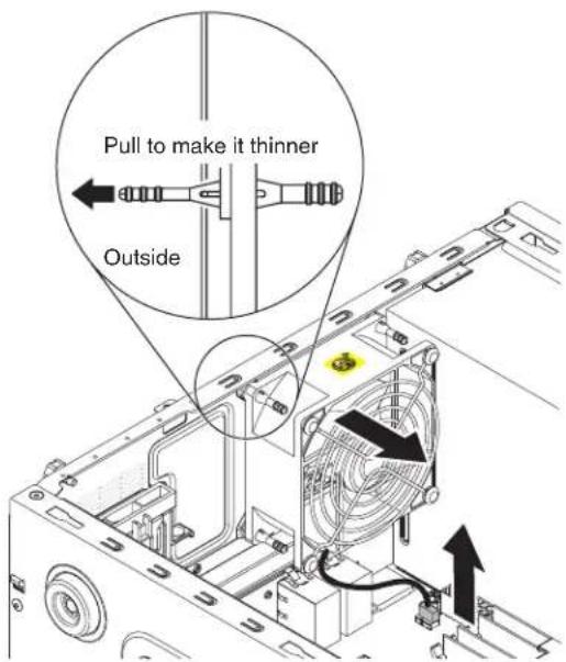
a. Disconnect the fan cable from the system board (see "System-board internal connectors" on page 17).
b. While you support the system fan with one hand, pull the rubber grommet away from the chassis to make it thinner; then, pull the fan toward the front of the server to remove the rubber grommet through the hole on the chassis. Repeat this step till all the remaining rubber grommets are removed.
c. Lift the system fan up and out of the chassis.
- If you are instructed to return the fan, follow all packaging instructions, and use any packaging materials for shipping that are supplied to you.
Installing the rear system fan
This procedure applies only to 4U server models with non-hot-swap power supplies.
Attention:
• To ensure proper cooling and airflow, do not operate the server for more than 30 minutes with the side cover removed.
To install the rear system fan on 4U server models with non-hot-swap power supplies, complete the following steps.
-
The replacement fan comes with the rubber grommets installed; however, they might have come out during shipment. If any of the rubber grommets are missing from the fan, install them on the fan before you continue. Use needle-nosed pliers to pull the grommets through the holes in the fan.
-
Carefully turn the server on its side so that it is lying flat, with the cover facing up.
Attention: Do not allow the server to fall over.
-
Remove the side cover (see "Removing the side cover" on page 166).
-
Remove the air duct.
-
Position the fan so that the grommets protrude through the holes in the chassis; then, use needle-nosed pliers to pull the grommets through the holes from outside the chassis.
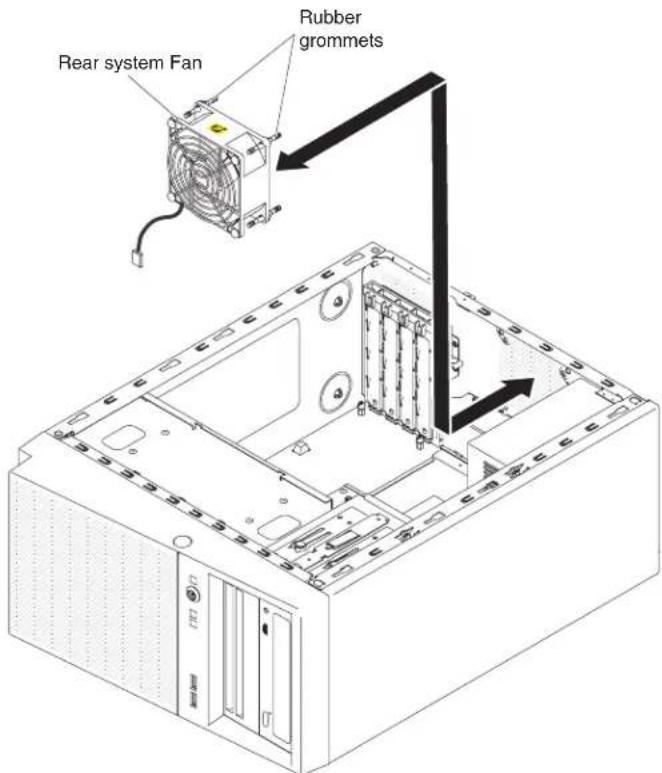
-
Connect the fan cable to the system board (see "System-board internal connectors" on page 17 for the location of the rear fan connector).
-
Install any adapters that you removed (see "Installing a ServeRAID adapter" on page 178).
-
Install the air duct.
-
Install the side cover (see "Installing the side cover" on page 167).
-
Stand the server back up in its vertical position.
-
Install bezel (see "installing the bezel" on page 1/1).
-
Reconnect the external cables and power cords; then, turn on the attached devices and turn on the server.
Removing the hard disk drive fan duct
This procedure applies only to the 5U server model with hot-swap power supplies (Model name: 2582-F4x).
Attention:
•To ensure proper cooling and airflow, do not operate the server for more than 30 minutes with the side cover removed.
To remove the hard disk drive fan duct on the 5U server model with hot-swap power supplies (Model name: 2582-F4x), complete the following steps.
- Turn off the server and all attached devices; then, disconnect all power cords and external cables.
- Unlock and remove the side cover (see "Removing the side cover" on page 166).
- Carefully turn the server on its side so that it is lying flat, with the system board facing up.
Attention: Do not allow the server to fall over.
- Unfasten the retention clips that secure the hard disk drive fan duct cable and then disconnect the hard disk drive fan duct cable from the system board.
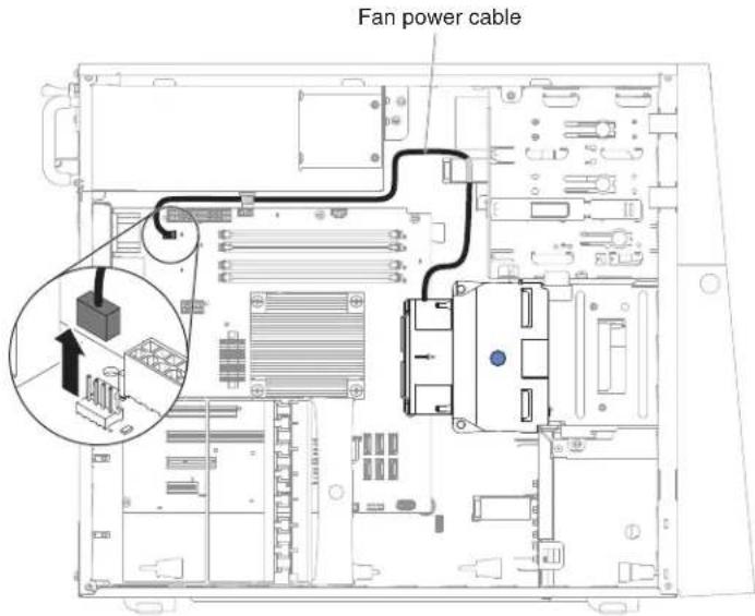
- Grasp the hard disk drive fan duct by the blue point and pull up to lift it out of the chassis.

- If you are instructed to return the fan, follow all packaging instructions, and use any packaging materials for shipping that are supplied to you.
Installing the hard disk drive fan duct
This procedure applies only to the 5U server model with hot-swap power supplies (Model name: 2582-F4x).
Attention:
•To ensure proper cooling and airflow, do not operate the server for more than 30 minutes with the side cover removed.
To install the hard disk drive fan duct on the 5U server model with hot-swap power supplies (Model name: 2582-F4x), complete the following steps.
-
Unlock and remove the side cover (see "Removing the side cover" on page 166).
-
Carefully turn the server on its side so that it is lying flat, with the system board facing up.
Attention: Do not allow the server to fall over.
- Lower the hard disk drive fan duct into the chassis, making sure the two guide pins and two latches on the chassis protrude through the respective holes on the hard disk drive fan duct.
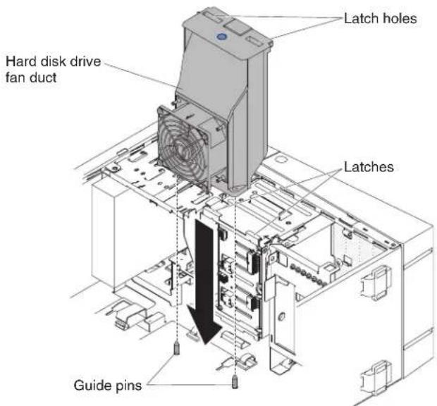
- Connect the hard disk drive fan duct cable to the system board (see "System-board internal connectors" on page 17 for the location of the fan assembly connector). Remember to insert the hard disk drive fan duct cable into the relevant retention clips.

-
Stand the server back up in its vertical position.
-
Install and lock the side cover (see "Installing the side cover" on page 167).
-
Reconnect the external cables and power cords; then, turn on the attached devices and turn on the server.
Removing and replacing consumable parts
Replacement of consumable parts is your responsibility. If IBM installs a consumable part at your request, you will be charged for the installation.
The illustrations in this document might differ slightly from your hardware.
Removing and replacing Tier 2 CRUs
You may install a Tier 2 CRU yourself or request IBM to install it, at no additional charge, under the type of warranty service that is designated for the server.
The illustrations in this document might differ slightly from your hardware.
Removing the simple-swap backplate
This procedure applies only to 4U server models with non-hot-swap power supplies.
To remove the simple-swap backplate on 4U server models with non-hot-swap power supplies, complete the following steps.
Note: You need a screwdriver in order to complete the steps.
- Read the safety information that begins on page vi and "Installation guidelines" on page 163.
- Turn off the server and all attached devices; then, disconnect all power cords and external cables.
- Remove the bezel (see "Removing the bezel" on page 169).
- Carefully turn the server on its side so that it is lying flat, with the cover facing up.
Attention: Do not allow the server to fall over.
- Remove the side cover (see "Removing the side cover" on page 166).
- Remove the air duct.
- Remove the simple-swap hard disk drives that are installed in the hard disk drive cage (see "Removing a simple-swap hard disk drive" on page 194).
- Disconnect the power cable and then the signal cable from the simple-swap backplate.
- Press and hold the drive cage release latches to pull the drive cage half out of the chassis.

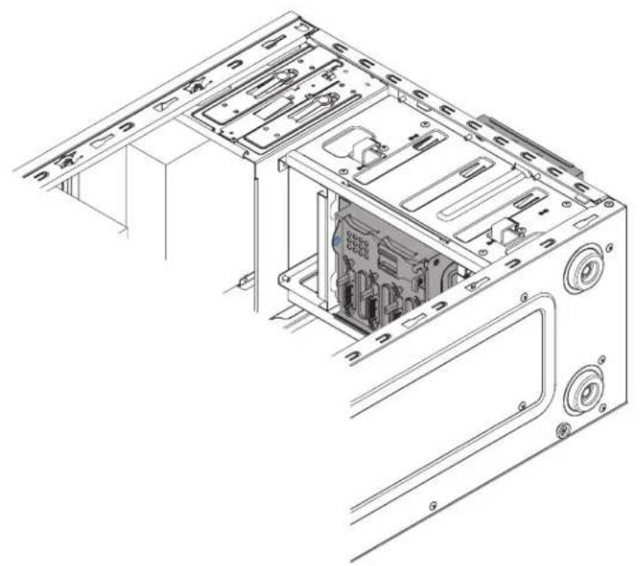
natural_image
Technical line drawing of an open computer tower case with internal components and ventilation ducts (no text or symbols)- Remove the backplate.

- If you are instructed to return the simple-swap backplate, follow all packaging instructions, and use any packaging materials for shipping that are supplied to you.
Installing the simple-swap backplate
This procedure applies only to 4U server models with non-hot-swap power supplies.
To install the simple-swap backplate on 4U server models with non-hot-swap power supplies, complete the following steps.
- Press and hold the drive cage release latches to pull the drive cage out.

- Align the bottom edge of the simple-swap backplate between the tabs and the bottom edge of the drive cage, and then rotate the simple-swap backplate toward the drive cage.
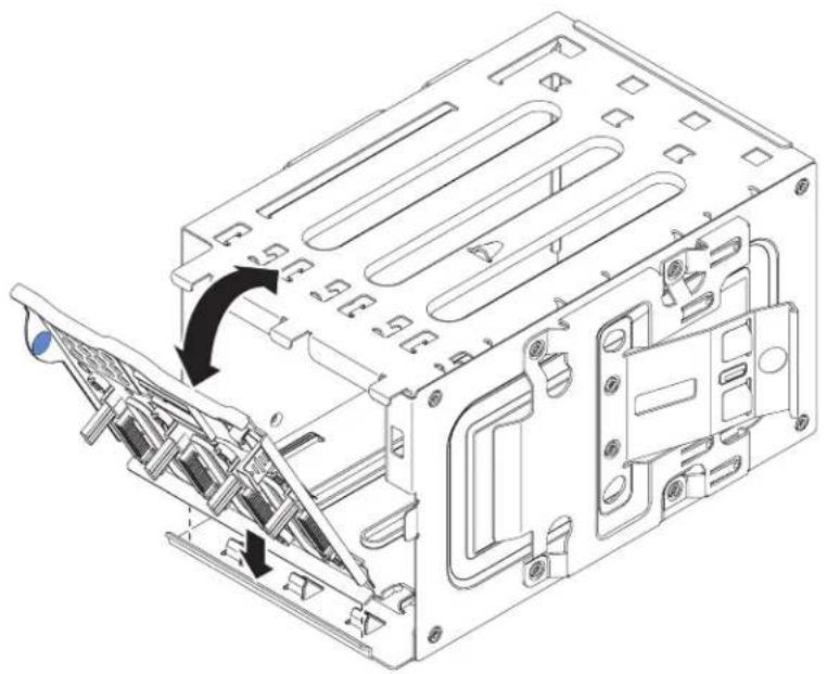
natural_image
Technical line drawing of a computer chassis with internal components and a directional arrow indicating movement (no text or symbols present)- Make sure the tabs on the simple-swap backplate are on the left of the upper drive cage tabs, and then push the backplate till the end.

natural_image
Technical line drawing of a computer chassis showing internal components and mounting holes (no text or symbols)- Slide the disk drive cage into the opening in the front of the server till half in.
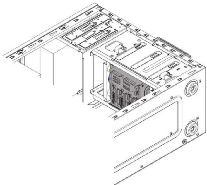
natural_image
Technical line drawing of an open computer tower case with internal components (no text or symbols)- Connect the hard disk drive power cables to the backplate (connector P3 to bay 3, connector P4 to bay 4, connector P5 to bay 5, and connector P6 to bay 6,).
- Connect the hard disk drive signal cables to the SATA connectors on the backplate (connector 0 to bay 3, connector 1 to bay 4, connector 2 to bay 5, and connector 3 to bay 6,)
- Connect the hard disk drive signal cables to the SATA connectors on the system board or the connector on the adapter (if one is installed).
Note: In the LSI RAID utility, SATA 1 represents hard disk drive in drive bay two and SATA 2 represents hard disk drive in drive bay one (see "nstalling a simple-swap hard disk drive" on page 196).
The following illustrations shows the SATA connectors on the system board:
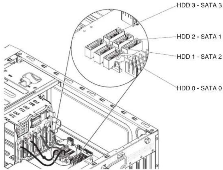
-
Secure the cables with the retention clips.
-
Press hard disk drive cage in until the release latches click into place.

-
Install the simple-swap hard disk drives that you removed from the hard disk drive cage (see "Installing a simple-swap hard disk drive" on page 196)
-
Install the air duct.
-
Install the side cover (see "Installing the side cover" on page 167).
-
Stand the server back up in its vertical position.
-
Install bezel (see "Installing the bezel" on page 171).
-
Reconnect the external cables and power cords; then, turn on the attached devices and turn on the server.
Removing the hot-swap hard disk drive backplane
This procedure applies only to the 5U server model with hot-swap power supplies (Model name: 2582-F4x).
To remove the hot-swap backplane on the 5U server model with hot-swap power supplies (Model name: 2582-F4x), complete the following steps.
-
Read the safety information that begins on page vi and "Installation guidelines" on page 163.
-
Turn off the server and all attached devices; then, disconnect all power cords and external cables.
-
Unlock and remove the side cover (see "Removing the side cover" on page 166).
-
Remove the lower bezel (see "Removing the lower bezel" on page 171).
-
Remove the hot-swap SAS/SATA hard disk drives installed in the hard disk drive cage (see "Removing a hot-swap hard disk drive" on page 198).
-
Carefully turn the server on its side so that it is lying flat, with the system board facing up.
Attention: Do not allow the server to fall over.
-
Remove the hard disk drive fan duct (see "Removing the hard disk drive fan duct" on page 214).
-
Press and hold the drive cage release tab; then, rotate the drive cage out of the chassis until the retaining tab on top of the cage locks into place.

- Disconnect the power, signal and configuration cables from the hard disk drive backplane.
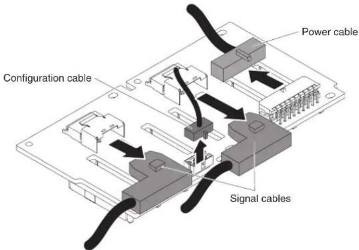
- Remove the four screws that secure the SAS/SATA hard disk drive backplane to the drive cage.

-
Lift the hot-swap backplane out of the lower lip on the drive cage and set it aside.
-
If you are instructed to return the SAS/SATA hard disk drive backplane, follow all packaging instructions, and use any packaging materials for shipping that are supplied to you.
Installing the hot-swap hard disk drive backplane
This procedure applies only to the 5U server model with hot-swap power supplies (Model name: 2582-F4x).
To install the hard disk drive backplane on the 5U server model with hot-swap power supplies (Model name: 2582-F4x), complete the following steps.
-
Place the bottom edge of the hot-swap hard disk drive backplane in the lower lip of the drive cage.
-
Connect the power, signal and configuration cables to the hard disk drive backplane.
Note: Make sure that Port 1 on the hardware ServeRAID is connected to Port 1 on the backplane. Likewise, Port 0 on the hardware ServeRAID should be connected to Port 0 on the backplane.

- Install the four screws that secure the hot-swap hard disk drive backplane to the drive cage.
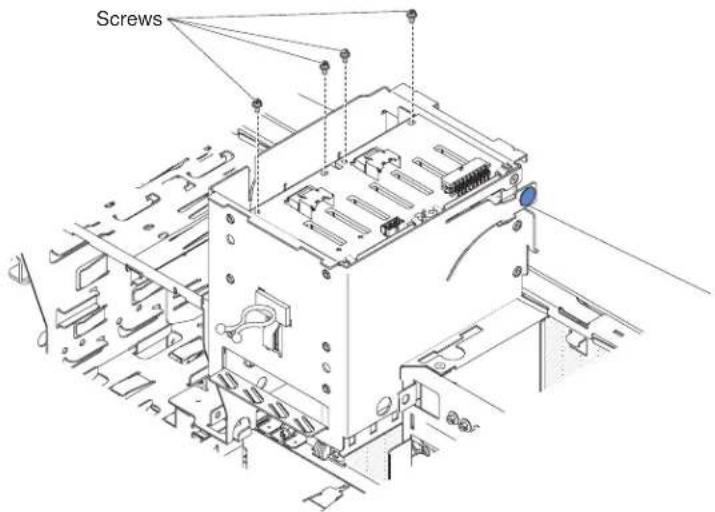
- Press and hold the retaining tab on the side of the cage; then, rotate the drive cage into the chassis until it locks into place.
Note: You may need to slightly lift up the cage in order to press and hold the retaining tab.
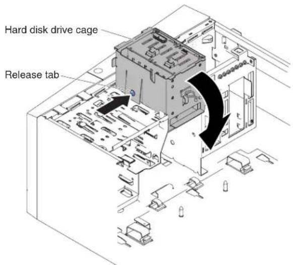
- Install the hard disk drive fan duct onto the hard disk drive cage (see "Installing the hard disk drive fan duct" on page 215).
- Stand the server back up in its vertical position.
- Install the hot-swap hard disk drives that you removed from the hard disk drive cage (see "Installing a hot-swap hard disk drive" on page 199).
- Install the lower bezel (see "Installing the lower bezel" on page 173).
- Install and lock the side cover (see "Installing the side cover" on page 167).
- Reconnect the external cables and power cords; then, turn on the attached devices and turn on the server.
Removing the front-panel assembly
To remove the front-panel assembly on 4U server models with non-hot-swap power supplies, complete the following steps. For the 5U server model with hot-swap power supplies (Model name: 2582-F4x), please see the next sub-section.
- Read the safety information that begins on page vi and "Installation guidelines" on page 163.
- Turn off the server and all attached devices; then, disconnect all power cords and external cables.
- Remove the bezel (see "Removing the bezel" on page 169).
- Carefully turn the server on its side so that it is lying flat, with the cover facing up.
Attention: Do not allow the server to fall over.
- Remove the side cover (see "Removing the side cover" on page 166).
- Remove the air duct.
- Disconnect the front-panel assembly cable from the system board, and note the routing of the cable (see "System-board internal connectors" on page 17 for the location of the front-panel connector).
- Press on top of the front-panel assembly and rotate the assembly toward the bottom of the server; then, remove the front-panel assembly from the chassis.

natural_image
Technical line drawing of an internal server rack with a highlighted internal component (no text or symbols)Note: Carefully pull the cable out from the opening. Do not allow the LED to disconnect from the front-panel assembly.
- If you are instructed to return the front-panel assembly, follow all packaging instructions, and use any packaging materials for shipping that are supplied to you.
To remove the front-panel assembly on the 5U server model with hot-swap power supplies (Model name: 2582-F4x), complete the following steps. For 4U server models with non-hot-swap power supplies, please see the above sub-section.
-
Read the safety information that begins on page vi and "Installation guidelines" on page 163.
-
Turn off the server and all attached devices; then, disconnect all power cords and external cables.
-
Unlock and remove the side cover (see "Removing the side cover" on page 168).
-
Remove the lower bezel (see "Removing the lower bezel" on page 171).
-
Remove the upper bezel (see "Removing the upper bezel" on page 174).
-
Slide the drives in bay 1 and bay 2 forward slightly (see "Removing a DVD drive" on page 184 and "Removing a tape drive" on page 188 for more information). It is not necessary to remove these drives.
-
Carefully turn the server on its side so that it is lying flat, with the system board facing up.
Attention: Do not allow the server to fall over.
-
Remove the hot-swap power supplies and the hot-swap power-supply cage (see "Removing the hot-swap power supply" on page 243) and "Removing the hot-swap power supply cage" on page 247).
-
Disconnect the front-panel assembly cable from the system board, and note the routing of the cable (see "System-board internal connectors" on page 1/ for the location of the front-panel connector).
-
Press up on the release tab of the front-panel assembly and pull the assembly toward the rear of the server; then, remove the front-panel assembly from the chassis.
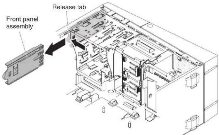
- If you are instructed to return the front-panel assembly, follow all packaging instructions, and use any packaging materials for shipping that are supplied to you.
Installing the front-panel assembly
To install the front-panel assembly on 4U server models with non-hot-swap power supplies, complete the following steps. For the 5U server model with hot-swap power supplies (Model name: 2582-F4x), please see the next sub-section.
- Reroute the front-panel assembly cable into the opening.
Note: Carefully pull the cable out from the opening. Do not allow the LED to disconnect from the front-panel assembly.
- Insert the bottom tabs of the front-panel assembly into the corresponding holes and rotate the assembly toward the chassis.
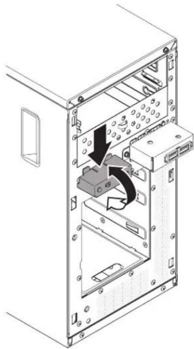
natural_image
Technical diagram of an internal server rack with a black arrow indicating a component (no text or symbols present)-
Push the front-panel assembly toward the chassis until it clicks into place.
-
Reroute and connect the front-panel assembly cable to the system board (see "System-board internal connectors" on page 17 for the location of the front-panel connector).
-
Install the air duct.
-
Install the side cover (see "Installing the side cover" on page 167).
-
Stand the server back up in its vertical position.
-
Install bezel (see "Installing the bezel" on page 171).
-
Reconnect the external cables and power cords; then, turn on the attached devices and turn on the server.
To install the front-panel assembly on the 5U server model with hot-swap power supplies (Model name: 2582-F4x), complete the following steps. For 4U server models with non-hot-swap power supplies, please see the above sub-section.
- Carefully turn the server on its side so that it is lying flat.
Attention: Do not allow the server to fall over.
-
Position the front end of the front-panel assembly in the channel above bay 1.
-
Push the front-panel assembly toward the front of the chassis until it clicks into place.
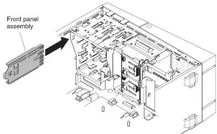
-
Reroute and connect the front-panel assembly cable to the system board (see "System-board internal connectors" on page 17 for the location of the front-panel connector).
-
Install the power-supply cage and the power supplies (see "Installing the hot-swap power supply cage" on page 249) and "Installing the hot-swap power supply" on page 245.
-
Push the drives in bay 1 and bay 2 into the drive bays (see "Installing a DVD drive" on page 185 and "Installing a tape drive" on page 190 for more information).
-
Stand the server back up in its vertical position.
-
Install the upper bezel (see "Installing the upper bezel" on page 175).
-
Install the lower bezel (see "Installing the lower bezel" on page 173).
-
Install and lock the side cover (see "Installing the side cover" on page 167).
-
Reconnect the external cables and power cords; then, turn on the attached devices and turn on the server.
Removing the front USB connector assembly
To remove the front USB connector assembly on 4U server models with non-hot-swap power supplies, complete the following steps. For the 5U server model with hot-swap power supplies (Model name: 2582-F4x), please see the next sub-section.
-
Read the safety information that begins on page vi and "Installation guidelines" on page 163.
-
Turn off the server and all attached devices; then, disconnect all power cords and external cables.
-
Remove the bezel (see "Removing the bezel" on page 169).
-
Carefully turn the server on its side so that it is lying flat, with the cover facing up.
Attention: Do not allow the server to fall over.
-
Remove the side cover (see "Removing the side cover" on page 166).
-
Remove the air duct.
-
Disconnect the front USB cable from the system board, and note the routing of the cable (see "System-board internal connectors" on page 17 for the location of the front USB connector).
-
Unscrew the front USB housing; then, tilt the top of the housing away from the chassis and lift the housing out of the opening in the chassis.
-
Pull the assembly out of the back of the housing.

natural_image
Technical diagram showing a mechanical assembly with a component and directional arrows indicating movement (no text or symbols present)- Carefully pull the front USB cable out of the opening in the chassis.
- If you are instructed to return the front USB connector assembly, follow all packaging instructions, and use any packaging materials for shipping that are supplied to you.
To remove the front USB connector assembly on the 5U server model with hot-swap power supplies (Model name: 2582-F4x), complete the following steps.
For 4U server models with non-hot-swap power supplies, please see the above sub-section.
- Read the safety information that begins on page vi and "Installation guidelines" on page 163.
- Turn off the server and all attached devices; then, disconnect all power cords and external cables.
- Unlock and remove the side cover (see "Removing the side cover" on page 166).
- Remove the lower bezel (see "Removing the lower bezel" on page 171).
- Remove the upper bezel (see "Removing the upper bezel" on page 174).
- Carefully turn the server on its side so that it is lying flat, with the system board facing up.
Attention: Do not allow the server to fall over.
- Disconnect the front USB cable from the system board, and note the routing of the cable (see "System-board internal connectors" on page 1/ or the location of the front USB connector).

- Stand the server back up in its vertical position.
- Press down and hold the release tab on the top of the front USB housing; then, tilt the top of the housing away from the chassis and lift the housing out of the opening in the chassis.
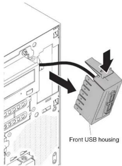
- Squeeze the spring clips on the sides of the front USB connector assembly and pull the assembly out of the back of the housing.
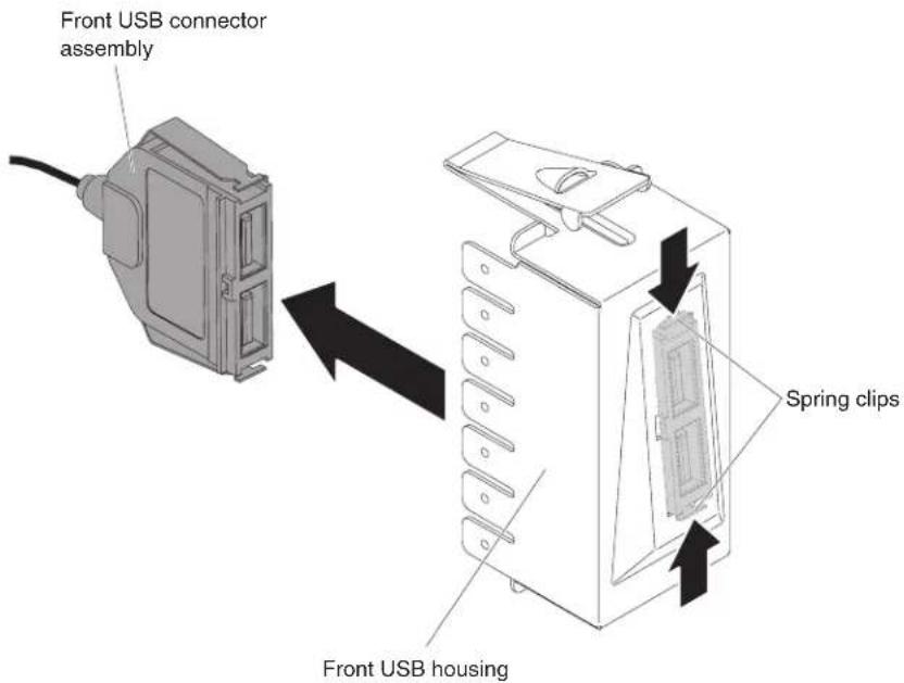
-
Carefully pull the front USB cable out of the opening in the chassis.
-
If you are instructed to return the front USB connector assembly, follow all packaging instructions, and use any packaging materials for shipping that are supplied to you.
Installing the front USB connector assembly
To install the front USB connector assembly on 4U server models with non-hot-swap power supplies, complete the following steps. For the 5U server model with hot-swap power supplies (Model name: 2582-F4x), please see the next sub-section.
-
Read the safety information that begins on page vi and "Installation guidelines" on page 163.
-
Turn off the server and all attached devices; then, disconnect all power cords and external cables.
-
Remove the bezel (see "Removing the bezel" on page 169).
-
Carefully turn the server on its side so that it is lying flat, with the cover facing up.
Attention: Do not allow the server to fall over.
-
Remove the side cover (see "Removing the side cover" on page 166).
-
Remove the air duct.
-
Carefully insert the front USB cable through the opening in the front of the chassis.

natural_image
Technical diagram showing a mechanical assembly with mounting brackets and a central control box, no visible text or symbols- Place the tab on the bottom edge of the USB housing into the bottom of the opening in the chassis.
- Tilt the top of the USB housing into position to the end.
- Secure the front USB housing with the screw.
- Reroute and connect the front USB cable to the front USB connector on the system board (see "System-board internal connectors" on page 17 for the location of the front USB connector).
- Install the air duct.
- Install the side cover (see "Installing the side cover" on page 167).
- Stand the server back up in its vertical position.
- Install bezel (see "Installing the bezel" on page 171).
- Reconnect the external cables and power cords; then, turn on the attached devices and turn on the server.
To install the front USB connector assembly on the 5U server model with hot-swap power supplies (Model name: 2582-F4x), complete the following steps. For 4U server models with non-hot-swap power supplies, please see the above sub-section.
- Read the safety information that begins on page vi and "Installation guidelines" on page 163.
- Turn off the server and all attached devices; then, disconnect all power cords and external cables.
- Unlock and remove the side cover (see "Removing the side cover" on page 166).
- Remove the lower bezel (see "Removing the lower bezel" on page 171).
- Remove the upper bezel (see "Removing the upper bezel" on page 174).
- Carefully insert the front USB cable through the opening in the front of the chassis.
- Squeeze the spring clips on the sides of the front USB connector assembly and insert the assembly into the housing through the back of the housing.
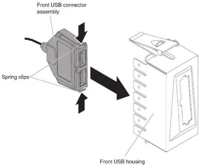
- Place the bottom edge of the housing into the bottom of the opening in the chassis; then, tilt the top of the housing into position until it clicks into place.
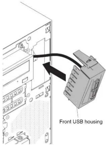
- Carefully turn the server on its side so that it is lying flat, with the system board facing up.
Attention: Do not allow the server to fall over.
- Reroute and connect the front USB cable to the front USB connector on the system board (see "System-board internal connectors" on page 17 for the location of the front USB connector).

-
Stand the server back up in its vertical position.
-
Install the upper bezel (see "Installing the upper bezel" on page 175).
-
Install the lower bezel (see "Installing the lower bezel" on page 173).
-
Install the and lock the side cover (see "Installing the side cover" on page 167).
-
Reconnect the external cables and power cords; then, turn on the attached devices and turn on the server.
Removing the rear adapter retention bracket
This procedure applies only to the 5U server model with hot-swap power supplies (Model name: 2582-F4x).
To remove the rear adapter-retention bracket on the 5U server model with hot-swap power supplies (Model name: 2582-F4x), complete the following steps.
-
Turn off the server and all attached devices; then, disconnect all power cords and external cables.
-
Unlock and remove the side cover (see "Removing the side cover" on page 166).
-
Carefully turn the server on its side so that it is lying flat, with the system board facing up.
Attention: Do not allow the server to fall over.
- Remove all adapters (if necessary) and place the adapters on a static-protective surface (see "Removing a ServeRAID adapter" on page 176).
Note: You might find it helpful to note where each adapter is installed before you remove the adapters.
-
Rotate the rear adapter-retention bracket to the open (unlocked) position.
-
Grasp the bracket on one side at the hinge point and pull inward (while you rotate the bracket slightly toward the front of the server) until the bracket is free of the hinge pin; then, grasp the bracket on the other side at the hinge point, pull inward until the bracket is free of the hinge pin, and remove the rear adapter-retention bracket from the server.
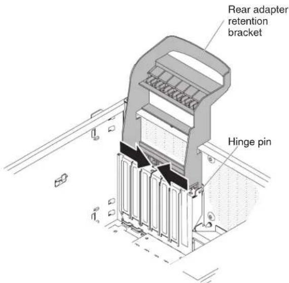
Installing the rear adapter retention bracket
This procedure applies only to the 5U server model with hot-swap power supplies (Model name: 2582-F4x).
To install the rear adapter-retention bracket on the 5U server model with hot-swap power supplies (Model name: 2582-F4x), complete the following steps.
- Position the rear adapter-retention bracket so that the hole in one of the hinge points is aligned with the hinge pin on the chassis; then, place the hinge pin through the hole on the chassis.
- Rotate the rear adapter-retention bracket into place so that the hole in the opposite hinge point snaps into place over the hinge pin on the chassis.
- Install the adapters.
- Stand the server back up in its vertical position.
- Install and lock the side cover (see "Installing the side cover" on page 167).
- Reconnect the external cables and power cords; then, turn on the attached devices and turn on the server.
Removing the hard disk drive cage
This procedure applies only to 4U server models with non-hot-swap power supplies.
To remove the hard disk drive cage on 4U server models with non-hot-swap power supplies, complete the following steps.
- Read the safety information that begins on page via and "Installation guidelines" on page 163.
- Turn off the server and all attached devices; then, disconnect all power cords and external cables.
- Remove the bezel (see "Removing the bezel" on page 169).
- Carefully turn the server on its side so that it is lying flat, with the cover facing up.
Attention: Do not allow the server to fall over.
-
Remove the side cover (see "Removing the side cover" on page 166).
-
Remove the air duct.
-
Remove the simple-swap hard disk drives (see "Removing a simple-swap hard disk drive" on page 194).
-
Remove the simple-swap backplate (see "Removing the simple-swap backplate" on page 217).
-
Press and hold the drive cage release latches.
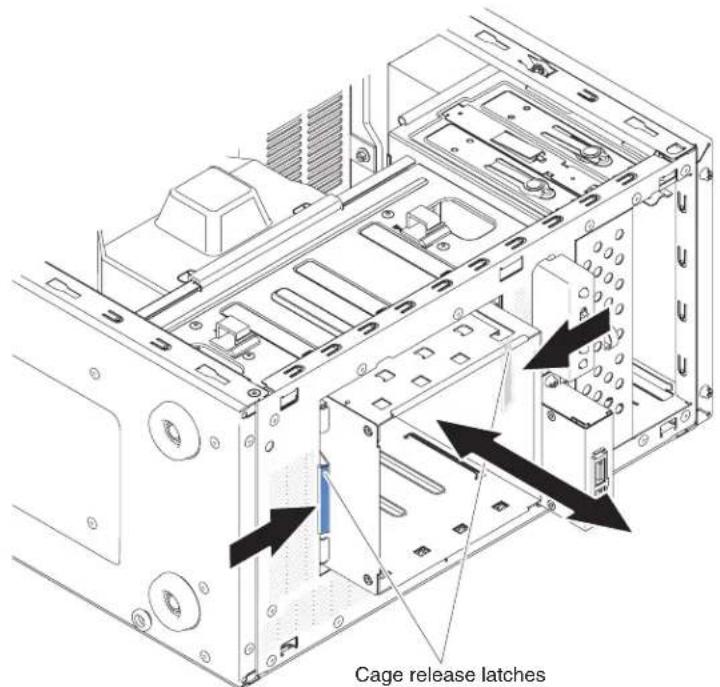
-
Carefully pull the hard disk drive cage and the cables out of the opening in the chassis.
-
If you are instructed to return the drive cage, follow all packaging instructions, and use any packaging materials for shipping that are supplied to you.
Installing the hard disk drive cage
This procedure applies only to 4U server models with non-hot-swap power supplies.
To install the hard disk drive cage on 4U server models with non-hot-swap power supplies, complete the following steps.
-
Read the safety information that begins on page 6 and "Installation guidelines" on page 163.
-
Turn off the server and all attached devices; then, disconnect all power cords and external cables.
-
Remove the bezel (see "Removing the bezel" on page 169).
-
Carefully turn the server on its side so that it is lying flat, with the cover facing up.
Attention: Do not allow the server to fall over.
-
Remove the side cover (see "Removing the side cover" on page 166).
-
Remove the air duct.
-
Press hard disk drive cage in until the release latches click into place.
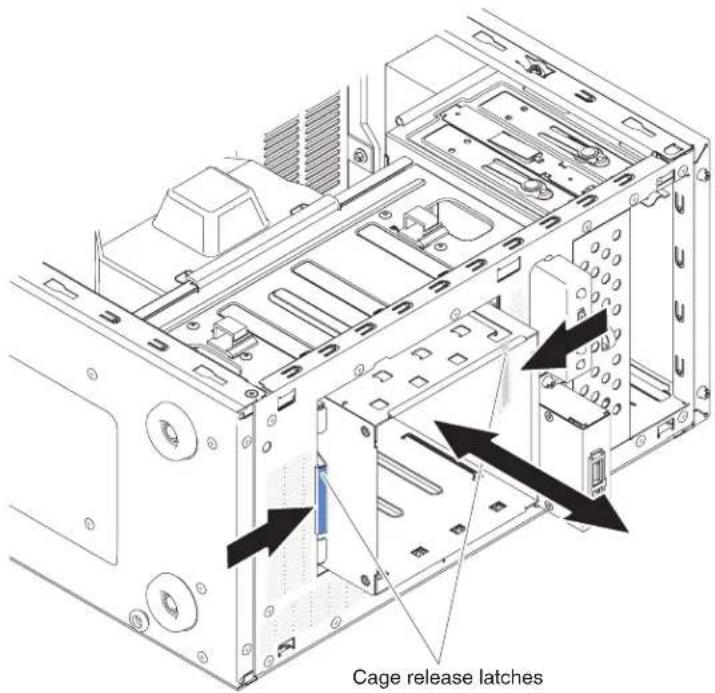
Note: Make sure the backplate is already installed on the disk drive cage (see "Installing the simple-swap backplate" on page 219).
-
Install the air duct.
-
Install the side cover (see "Installing the side cover" on page 167).
-
Stand the server back up in its vertical position.
-
Install bezel (see "installing the bezel" on page 171).
-
Reconnect the external cables and power cords; then, turn on the attached devices and turn on the server.
Removing the non-hot-swap power supply
This procedure applies only to 4U server models with non-hot-swap power supplies.
When you remove or install a non-hot-swap power supply on 4U server models with non-hot-swap power supplies, observe the following precautions.
Statement 8:
CAUTION:
Never remove the cover on a power supply or any part that has the following label attached.

Hazardous voltage, current, and energy levels are present inside any component that has this label attached. There are no serviceable parts inside these components. If you suspect a problem with one of these parts, contact a service technician.
To remove a non-hot-swap power supply on 4U server models with non-hot-swap power supplies, complete the following steps.
-
Read the safety information that begins on page vi and "Installation guidelines" on page 163.
-
Turn off the server and all attached devices; then, disconnect all power cords and external cables.
-
Carefully turn the server on its side so that it is lying flat, with the cover facing up.
Attention: Do not allow the server to fall over.
-
Remove the side cover (see "Removing the side cover" on page 166).
-
Remove the air duct.
-
Remove the heat sink (see "Removing the microprocessor and heat sink" on page 250).
-
Disconnect the hard disk power cables from the backplate.
-
Disconnect the cables from the power supply to the system board and all internal components. Note the routing of all power-supply cables; you will need to route the power-supply cables the same way when you install the power supply.
Attention: Support the power supply while you remove the mounting screws. After the screws are removed, the power supply is loose and can damage other components in the server.
- While you support the power supply, remove the screws that secure it to the chassis; then, lift the power supply out of the chassis. Save the screws to use when you install the replacement power supply.
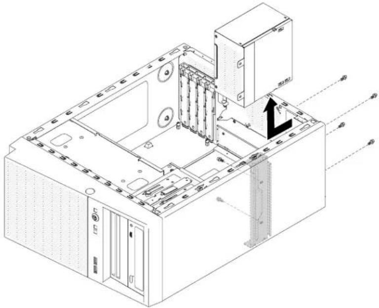
natural_image
Isometric technical diagram of a computer tower with internal components and ventilation duct (no text or labels)Note: You may find it easier to remove the power supply by pushing the bottom upward. Do not pull the cables.
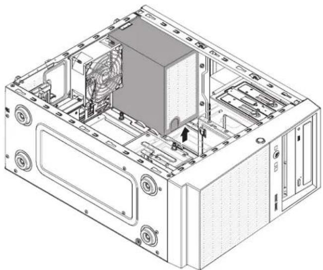
natural_image
Technical line drawing of a computer tower case with visible internal components and ventilation slots (no text or labels)- If you are instructed to return the power supply, follow all packaging instructions, and use any packaging materials for shipping that are supplied to you.
Installing the non-hot-swap power supply
This procedure applies only to 4U server models with non-hot-swap power supplies.
Statement 8:
CAUTION:
Never Remove the server top cover on a power supply or any part that has the following label attached.

Hazardous voltage, current, and energy levels are present inside any component that has this label attached. There are no serviceable parts inside these components. If you suspect a problem with one of these parts, contact a service technician.
To install a non-hot-swap power supply on 4U server models with non-hot-swap power supplies, complete the following steps.
- Remove the air duct.
- Remove the heat sink (see "Removing the microprocessor and heat sink" on page 250).
- Position the power supply in the chassis so that the screw holes in the power supply are aligned with the corresponding holes in the rear of the chassis.

natural_image
Isometric technical diagram of a computer tower with internal components and ventilation ducts (no text or labels)Note: Make sure the top and the bottom of the power supply align with the upper and lower tabs on the opening.

natural_image
3D diagram of a computer tower with fan and directional arrow indicating movement (no text or symbols)- Install the screws that secure the power supply to the chassis.
- Install the air duct.
- Install the side cover (see "Installing the side cover" on page 167).
- Stand the server back up in its vertical position.
- Install bezel (see "Installing the bezel" on page 171).
- Reconnect the external cables and power cords; then, turn on the attached devices and turn on the server.
Removing the hot-swap power supply
This procedure applies only to the 5U server model with hot-swap power supplies (Model name: 2582-F4x).
When you remove or install a hot-swap power supply on the 5U server model with hot-swap power supplies (Model name: 2582-F4x), observe the following precautions.
Statement 5:

CAUTION:
The power control button on the device and the power switch on the power supply do not turn off the electrical current supplied to the device. The device also might have more than one power cord. To remove all electrical current from the device, ensure that all power cords are disconnected from the power source.
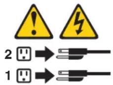
Statement 8:

CAUTION:
Never Remove the server top cover on a power supply or any part that has the following label attached.
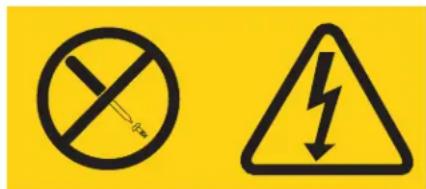
Hazardous voltage, current, and energy levels are present inside any component that has this label attached. There are no serviceable parts inside these components. If you suspect a problem with one of these parts, contact a service technician.
Attention: During normal operation, each power-supply bay must contain either a hot-swap power supply or a hot-swap power-supply filler for proper cooling.
To remove a hot-swap power supply on server models with hot-swap power supplies (5U chassis), complete the following steps.
- Read the safety information that begins on page vi and "Installation guidelines" on page 163.
- Disconnect the power cord from the power supply that is to be removed.
- Press down on the orange release lever and pull the power supply out of the bay, using the handle.
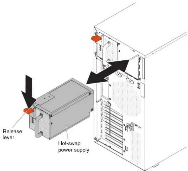
- If you are instructed to return the power supply, follow all packaging instructions, and use any packaging materials for shipping that are supplied to you.
Installing the hot-swap power supply
This procedure applies only to the 5U server model with hot-swap power supplies (Model name: 2582-F4x).
The following items describe the type of power supply that the server supports and other information that you must consider when you install a power supply:
•To confirm that the server supports the power supply that you are installing, see http://www.ibm.com/systems/info/x86servers/serverproven/compat/us/.
•The server comes standard with one 430-watt hot-swap power supply. The input voltage is 110 V ac or 220 V ac auto-sensing.
•These power supplies are designed for parallel operation. In the event of a power-supply failure, the redundant power supply continues to power the system. The server supports a maximum of two power supplies.
- The server can run fully configured with one power supply. For redundancy support, you must install the second hot-swap power supply.
Note: You cannot mix high-efficiency and non-high-efficiency power supplies in the server.
Statement 5:

CAUTION:
The power control button on the device and the power switch on the power supply do not turn off the electrical current supplied to the device. The device also might have more than one power cord. To remove all electrical current from the device, ensure that all power cords are disconnected from the power source.
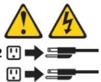
Statement 8:
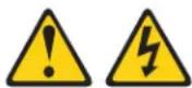
CAUTION:
Never Remove the server top cover on a power supply or any part that has the following label attached.

Hazardous voltage, current, and energy levels are present inside any component that has this label attached. There are no serviceable parts inside these components. If you suspect a problem with one of these parts, contact a service technician.
Attention: During normal operation, each power-supply bay must contain either a power supply or power-supply filler for proper cooling.
To install a hot-swap power supply on the 5U server model with hot-swap power supplies (Model name: 2582-F4x), complete the following steps.
- Place the power supply into the bay guides.
- Using the handle, push the power supply toward the front of the chassis until it locks into place.

- Connect one end of the power cord into the connector on the back of the power supply and connect the other end of the power cord into a properly grounded electrical outlet.
- Make sure that both the ac and dc power LEDs on the rear of the power supply are lit, indicating that the power supply is operating correctly.
- If you are adding a power supply to the server, attach the redundant power information label that comes with this option on the server top cover near the power supplies.

Removing the hot-swap power supply cage
This procedure applies only to the 5U server model with hot-swap power supplies (Model name: 2582-F4x).
To remove the hot-swap power-supply cage on the 5U server model with hot-swap power supplies (Model name: 2582-F4x), complete the following steps.
- Read the safety information that begins on page vi and "Installation guidelines" on page 163.
- Turn off the server and all attached devices; then, disconnect all power cords and external cables.
- Unlock and remove the side cover (see "Removing the side cover" on page 166).
- Remove the hot-swap power supplies (see "Removing the hot-swap power supply" on page 243).
- Carefully turn the server on its side so that it is lying flat, with the system board facing up.
Attention: Do not allow the server to fall over.
- Disconnect the cables from the power-supply cage to the system board and all internal components.
- Remove the two screws that secure the power-supply cage to the chassis; the two screws are located in the front of the hot-swap power supply cage.

- Remove the other four screws that also secure the power-supply cage to the chassis; then, slide the cage toward the front of the server to disengage the retaining clips from the top of the chassis and lift the cage out of the chassis.
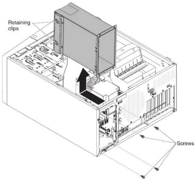
- If you are instructed to return the power-supply cage, follow all packaging instructions, and use any packaging materials for shipping that are supplied to you.
Installing the hot-swap power supply cage
This procedure applies only to the 5U server model with hot-swap power supplies (Model name: 2582-F4x).
To install the hot-swap power supply cage on the 5U server model with hot-swap power supplies (Model name: 2582-F4x), complete the following steps.
- Place the power-supply cage into the chassis and slide it toward the rear of the server until the retaining clips engage the top of the chassis, then install the four screws to secure the power-supply cage to the chassis.
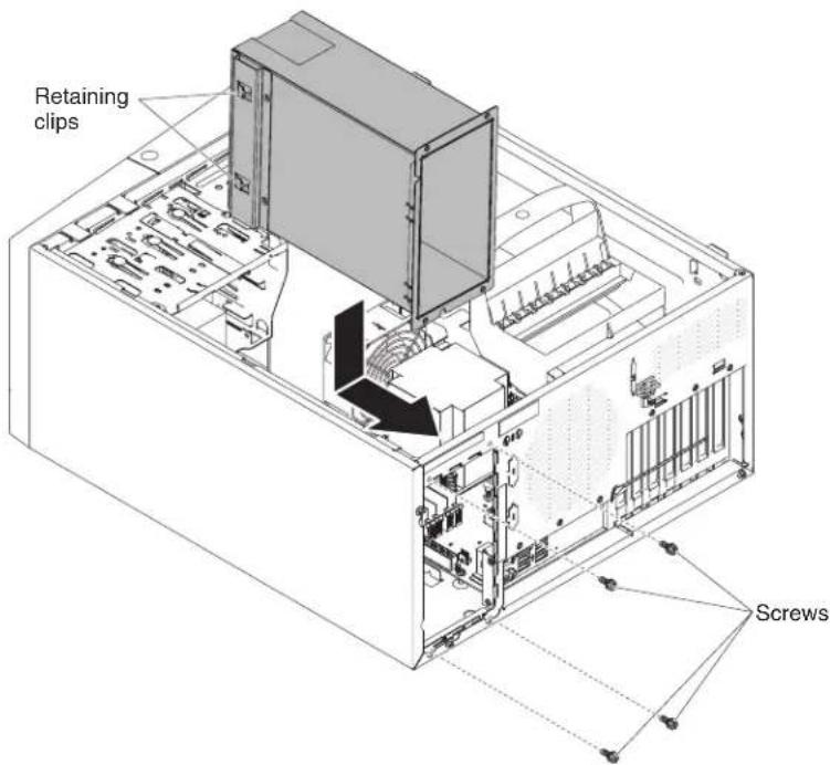
-
Install the other two screws to further secure the power-supply cage to the chassis, which is located in front of the power-supply cage.
-
Connect the cables from the power-supply cage to the system board and all internal components (see "System-board internal connectors" on page 17 for the locations of the internal connectors).
-
Stand the server back up in its vertical position.
-
Reinstall the hot-swap power supplies (see "Installing the hot-swap power supply" on page 245).
-
Install and lock the side cover (see "Installing the side cover" on page 167).
-
Reconnect the external cables and power cords; then, turn on the attached devices and turn on the server.
Removing and replacing FRUs
Field replaceable units (FRUs) must be installed only by trained service technicians.
Removing the microprocessor and heat sink
To remove the microprocessor and heat sink on 4U server models with non-hot-swap power supplies, complete the following steps. For the 5U server model with hot-swap power supplies (Model name: 2582-F4x), please see the next sub-section.
-
Read the safety information that begins on page vi and "Installation guidelines" on page 163.
-
Turn off the server and all attached devices; then, disconnect all power cords and external cables.
-
Carefully turn the server on its side so that it is lying flat, with the cover facing up.
Attention: Do not allow the server to fall over.
-
Remove the side cover (see "Removing the side cover" on page 166).
-
Remove the air duct.
-
Remove the heat sink from the microprocessor:
Attention: The heat sink may become very hot during normal operation. Allow time for the heat sink to cool down before you touch it.
a. Loosen the screws and alternate among the screws until they break the seal with the microprocessor.
b. Press firmly on the captive screws and loosen them with a screwdriver.
c. Use your fingers to gently pull the heat sink from the microprocessor.
Important: Be careful when you handle the microprocessor and heat sink. If the microprocessor and heat sink will be reused, do not contaminate the thermal material between them.
Attention: The microprocessor retention latch is spring-loaded when the microprocessor is in place. Releasing the latch too quickly or allowing it to spring upward can damage the microprocessor and surrounding components.
- Release the microprocessor retention latch by pressing down on the end, moving it to the side, and slowly releasing it to the open (up) position.
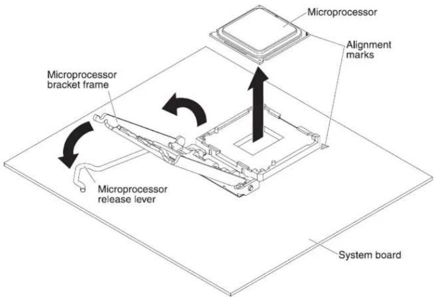
- Open the microprocessor bracket frame by lifting up the tab on the top edge.
- Carefully lift the microprocessor straight up and out of the socket, and place it on a static-protective surface.
- If you are instructed to return the microprocessor and heat sink, follow all packaging instructions, and use any packaging materials for shipping that are supplied to you.
To remove the microprocessor and heat sink on the 5U server model with hot-swap power supplies (Model name: 2582-F4x), complete the following steps. For 4U server models with non-hot-swap power supplies, please see the above sub-section.
- Read the safety information that begins on page vi and "Installation guidelines" on page 163.
- Turn off the server and all attached devices; then, disconnect all power cords and external cables.
- Unlock and remove the side cover (see "Removing the side cover" on page 166).
- Carefully turn the server on its side so that it is lying flat, with the system board facing up.
Attention: Do not allow the server to fall over.
- Rotate the rear adapter-retention bracket to the open (unlocked) position.
- Remove the heat sink from the microprocessor:
Attention: The heat sink may become very hot during normal operation. Allow time for the heat sink to cool down before you touch it.
a. Loosen the screws and alternate among the screws until they break the seal with the microprocessor.
b. Press firmly on the captive screws and loosen them with a screwdriver.
c. Use your fingers to gently pull the heat sink from the microprocessor.
Important: Be careful when you handle the microprocessor and heat sink. If the microprocessor and heat sink will be reused, do not contaminate the thermal material between them.

Attention: The microprocessor retention latch is spring-loaded when the microprocessor is in place. Releasing the latch too quickly or allowing it to spring upward can damage the microprocessor and surrounding components.
- Release the microprocessor retention latch by pressing down on the end, moving it to the side, and slowly releasing it to the open (up) position.

-
Open the microprocessor bracket frame by lifting up the tab on the top edge.
-
Carefully lift the microprocessor straight up and out of the socket, and place it on a static-protective surface.
-
If you are instructed to return the microprocessor and heat sink, follow all packaging instructions, and use any packaging materials for shipping that are supplied to you.
Installing a microprocessor and heat sink
To install the microprocessor and heat sink on 4U server models with non-hot-swap power supplies, complete the following steps. For the 5U server model with hot-swap power supplies (Model name: 2582-F4x), please see the next sub-section.
-
Touch the static-protective package that contains the microprocessor to any unpainted metal surface on the server. Then, remove the microprocessor from the package.
-
Remove the protective cover, tape, or label from the surface of the microprocessor socket, if any is present.
-
Rotate the release lever on the microprocessor socket to the fully open position.
Attention: Make sure that the release lever on the microprocessor socket is in the fully open position before you insert the microprocessor in the socket. Failure to do so might result in permanent damage to the microprocessor, microprocessor socket, and system board.
- Carefully grasp the microprocessor and place the microprocessor into the microprocessor socket.
Note: To maintain correct orientation between the microprocessor and the microprocessor socket during installation, observe the following information:
•The microprocessor has two notches that are keyed to two tabs on the sides of the socket.
- A triangle-shaped indicator on one corner of the microprocessor points to a 45-degree angle on the system board.
- Do not use excessive force when you press the microprocessor into the socket.
- Close the microprocessor bracket frame; then, close the microprocessor retention latch and lock it securely in place.

- Install the heat sink:
Attention: Do not touch the thermal material on the bottom of the heat sink. Touching the thermal material will contaminate it. If the thermal material on the microprocessor or heat sink becomes contaminated, contact your service technician.
a. Align the screw holes on the heat sink with the holes on the system board.
b. Tighten the screws with a screwdriver, alternating among the screws until they are tight. If possible, each screw should be rotated two full rotations at a time. Repeat until the screws are tight. Do not overtighten the screws by using excessive force.
Important: Do not touch the thermal material on the bottom of the heat sink. Touching the thermal material will contaminate it. If the thermal material on the microprocessor or heat sink becomes contaminated, contact your service technician.
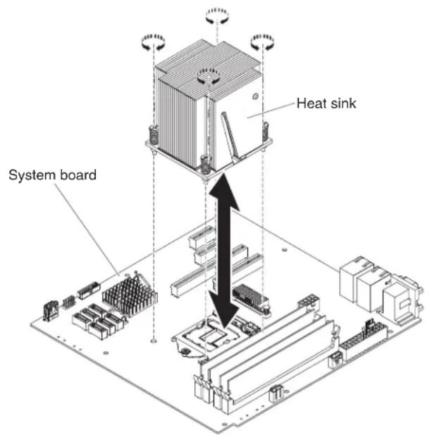
- Reconnect any cables that you disconnected during the removal of the old microprocessor.
- Secure the SATA signal cables with the retention-clips.
- Install the air duct.
- Install the side cover (see "Installing the side cover" on page 167).
- Stand the server back up in its vertical position.
- Install bezel (see "Installing the bezel" on page 171).
- Reconnect the external cables and power cords; then, turn on the attached devices and turn on the server.
To install the microprocessor and heat sink on the 5U server model with hot-swap power supplies (Model name: 2582-F4x), complete the following steps. For 4U server models with non-hot-swap power supplies, please see the above sub-section.
-
Touch the static-protective package that contains the microprocessor to any unpainted metal surface on the server. Then, remove the microprocessor from the package.
-
Remove the protective cover, tape, or label from the surface of the microprocessor socket, if any is present.
- Rotate the release lever on the microprocessor socket to the fully open position.
Attention: Make sure that the release lever on the microprocessor socket is in the fully open position before you insert the microprocessor in the socket. Failure to do so might result in permanent damage to the microprocessor, microprocessor socket, and system board.
- Carefully grasp the microprocessor and place the microprocessor into the microprocessor socket.
Note: To maintain correct orientation between the microprocessor and the microprocessor socket during installation, observe the following information:
- The microprocessor has two notches that are keyed to two tabs on the sides of the socket.
- A triangle-shaped indicator on one corner of the microprocessor points to a 45-degree angle on the system board.
-
Do not use excessive force when you press the microprocessor into the socket.
-
Close the microprocessor bracket frame; then, close the microprocessor retention latch and lock it securely in place.

- Install the heat sink:
Attention: Do not touch the thermal material on the bottom of the heat sink. Touching the thermal material will contaminate it. If the thermal material on the microprocessor or heat sink becomes contaminated, contact your service technician.
a. Align the screw holes on the heat sink with the holes on the system board.
b. Tighten the screws with a screwdriver, alternating among the screws until they are tight. If possible, each screw should be rotated two full rotations at a time. Repeat until the screws are tight. Do not overtighten the screws by using excessive force.
Important: Do not touch the thermal material on the bottom of the heat sink. Touching the thermal material will contaminate it. If the thermal material on the microprocessor or heat sink becomes contaminated, contact your service technician.
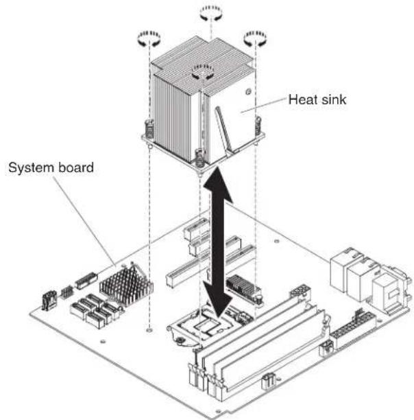
- Reconnect any cables that you disconnected during the removal of the old microprocessor.
- Rotate the rear adapter-retention bracket to the closed (locked) position.
- Stand the server back up in its vertical position.
- Install and lock the side cover (see "Installing the side cover" on page 167).
- Reconnect the external cables and power cords; then, turn on the attached devices and turn on the server.
Thermal grease
The thermal grease must be replaced whenever the heat sink has been removed from the top of the microprocessor and is going to be reused or when debris is found in the grease.
When you are installing the heat sink on the same microprocessor that is was removed from, make sure that:
•The thermal grease on the heat sink and microprocessor is not contaminated.
•Additional thermal grease is not added to the existing thermal grease on the heat sink and microprocessor.
Note:
- Read the Safety information on page vii
- Read the "Installation guidelines" on page 163.
- Read "Handling static-sensitive devices" on page 165.
To replace damaged or contaminated thermal grease on the microprocessor and heat sink, complete the following steps.
- Place the heat sink on a clean work surface.
-
Remove the cleaning pad from its package and unfold it completely.
-
Use the cleaning pad to wipe the thermal grease from the bottom of the heat sink.
Note: Make sure that all of the thermal grease is removed.
- Use a clean area of the cleaning pad to wipe the thermal grease from the microprocessor; then, dispose of the cleaning pad after all of the thermal grease is removed.
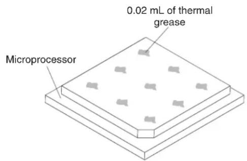
- Use the thermal-grease syringe to place 9 uniformly spaced dots of 0.02 mL each on the top of the microprocessor. The outermost dots must be within approximately 5 mm of the edge of the microprocessor, this is to ensure uniform distribution of the grease.

Note: If the grease is properly applied, approximately half of the grease will remain in the syringe.
- Install the heat sink onto the microprocessor as described in "Installing a microprocessor and heat sink" on page 254.
Removing the system board
To remove the system board on 4U server models with non-hot-swap power supplies, complete the following steps. For the 5U server model with hot-swap power supplies (Model name: 2582-F4x), please see the next sub-section.
- Read the safety information that begins on page vi and "Installation guidelines" on page 163.
- Turn off the server and all attached devices; then, disconnect all power cords and external cables.
- Carefully turn the server on its side so that it is lying flat, with the cover facing up.
Attention: Do not allow the server to fall over.
- Remove the side cover (see "Removing the side cover" on page 166).
- Remove the air duct.
- Remove the microprocessor and heat sink (see "Removing the microprocessor and heat sink" on page 250).
Attention: Remove the socket covers from the microprocessor sockets on the new system board and place them on the microprocessor sockets of the system board you are removing.
- Pull the drive cage half out of the chassis.

natural_image
Technical line drawing of an open computer tower case with internal components (no text or symbols)-
Disengage the cables from any retention-clips.
-
Note where each cable is connected; then, disconnect all cables from the system board.
Attention: Disengage all latches, release tabs or locks on cable connectors when you disconnect all cables from the system board. Failing to release them before removing the cables will damage the cable sockets on the system board. The cable sockets on the system board are fragile. Any damage to the cable sockets may require replacing the system board.
- Remove any of the following components (in addition to others that might not be listed) that are installed on the system board and put them in a safe, static-protective place:
- Adapters (see "Removing a ServeRAID adapter" on page 176).
•DIMMs (see "Installing a memory module" on page 203).
- Battery (see "Removing the system battery" on page 207).
- Remove the seven screws that secure the system board to the chassis.

-
Carefully lift the system board out of the server.
-
If you are instructed to return the system board, follow all packaging instructions, and use any packaging materials for shipping that are supplied to you.
Attention: Make sure to place the socket covers for the microprocessor sockets on the system board before returning the system board.
To remove the system board on the 5U server model with hot-swap power supplies (Model name: 2582-F4x), complete the following steps. For 4U server models with non-hot-swap power supplies, please see the above sub-section.
-
Read the safety information that begins on page vii and "Installation guidelines" on page 163.
-
Turn off the server and all attached devices; then, disconnect all power cords and external cables.
-
Unlock and remove the side cover (see "Removing the side cover" on page 166).
-
Carefully turn the server on its side so that it is lying flat, with the system board facing up.
Attention: Do not allow the server to fall over.
-
Rotate the rear adapter-retention bracket to the open (unlocked) position.
-
Remove the hard disk drive fan duct (see "Removing the hard disk drive fan duct" on page 214).
-
Remove the microprocessor and heat sink (see "Removing the microprocessor and heat sink" on page 250).
Attention: Remove the socket covers from the microprocessor sockets on the new system board and place them on the microprocessor sockets of the system board you are removing.
-
Disengage the cables from any retention-clips.
-
Note where each cable is connected; then, disconnect all cables from the system board.
Attention: Disengage all latches, release tabs or locks on cable connectors when you disconnect all cables from the system board. Failing to release them before removing the cables will damage the cable sockets on the system board. The cable sockets on the system board are fragile. Any damage to the cable sockets may require replacing the system board.
- Remove any of the following components (in addition to others that might not be listed) that are installed on the system board and put them in a safe, static-protective place:
- Adapters (see "Removing a ServeRAID adapter" on page 176).
- DIMMs (see "Installing a memory module" on page 203).
- Battery (see "Removing the system battery" on page 207).
- Remove the seven screws that secure the system board to the chassis.
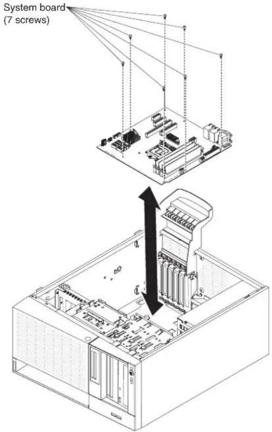
-
Carefully lift the system board out of the server.
-
If you are instructed to return the system board, follow all packaging instructions, and use any packaging materials for shipping that are supplied to you.
Attention: Make sure to place the socket covers for the microprocessor sockets on the system board before returning the system board.
Installing the system board
Notes:
-
When you reassemble the components in the server, be sure to route all cables carefully so that they are not exposed to excessive pressure.
-
When you replace the system board, you must either update the server with the latest firmware or restore the pre-existing firmware that the customer provides on a diskette or CD image. Make sure that you have the latest firmware or a copy of the pre-existing firmware before you proceed. See "Updating the firmware" on page 267, "Updating the Universal Unique Identifier (UUID)" on page 286, and "Updating the DMI/SMBIOS data" on page 289 for more information.
Important: Some cluster solutions require specific code levels or coordinated code updates. If the device is part of a cluster solution, verify that the latest level of code is supported for the cluster solution before you update the code
To install the system board on 4U server models with non-hot-swap power supplies, complete the following steps. For the 5U server model with hot-swap power supplies (Model name: 2582-F4x), please see the next sub-section.
-
Read the safety information that begins on page vi and "Installation guidelines" on page 163.
-
Pull the drive cage half out of the chassis.
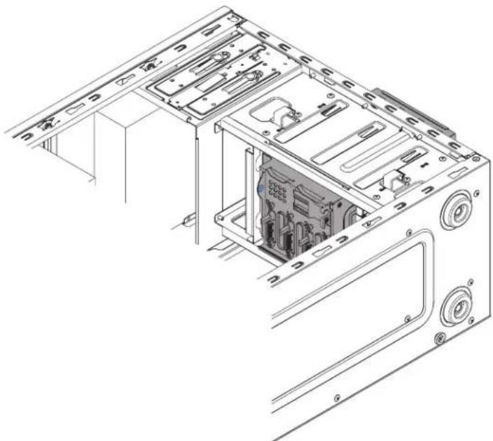
natural_image
Technical line drawing of an internal computer tower case with visible internal components and mounting brackets (no text or labels)-
Touch the static-protective package that contains the system board to any unpainted metal surface on the server. Then, remove the system board from the package.
-
Insert the system board into the chassis and slide it toward the rear of the server until the screw holes on the system board align with the screw holes on the chassis.

- Install the seven screws that secure the system board to the chassis.
- Install any of the following components that you removed from the system board:
•SAS/SATA ServeRAID adapter (see "Installing a ServeRAID adapter" on page 178). - Battery (see "Installing the system battery" on page 209).
•DIMMs (see "Installing a memory module" on page 203). - Microprocessor and heat sink (see "Installing a microprocessor and heat sink" on page 254).
- Adapters (see "Installing a ServeRAID adapter" on page 178).
- Reconnect any cables to the system board that you disconnected during removal (see "System-board internal connectors" on page 1/).
- Secure the cables with the retention-clips.
- Install the air duct.
- Install the side cover (see "Installing the side cover" on page 167).
- Stand the server back up in its vertical position.
- Install bezel (see "Installing the bezel" on page 171).
- Reconnect the external cables and power cords; then, turn on the attached devices and turn on the server.
Important: Perform the following updates:
- Either update the server with the latest RAID firmware or restore the pre-existing firmware from a diskette or CD image.
- Update the UUID (see "Updating the Universal Unique Identifier (UUID)" on page 286).
- Update the DMI/SMBIOS (see "Updating the DMI/SMBIOS data" on page 289).
- Clear the CMOS data (see JP1 in "System-board switches and jumpers" on page 19).
To install the system board on the 5U server model with hot-swap power supplies (Model name: 2582-F4x), complete the following steps. For 4U server models with non-hot-swap power supplies, please see the above sub-section.
-
Read the safety information that begins on page vii and "Installation guidelines" on page 163.
-
Touch the static-protective package that contains the system board to any unpainted metal surface on the server. Then, remove the system board from the package.
-
Insert the system board into the chassis and slide it toward the rear of the server until the screw holes on the system board align with the screw holes on the chassis.
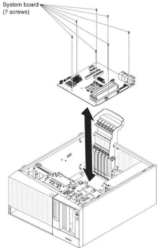
-
Install the seven screws that secure the system board to the chassis.
-
Install any of the following components that you removed from the system board:
- Adapters (see "Installing a ServeRAID adapter" on page 178).
- Battery (see "Installing the system battery" on page 209).
- DIMMs (see "Installing a memory module" on page 203).
- Microprocessor and heat sink (see "Installing a microprocessor and heat sink" on page 254).
-
Reconnect any cables to the system board that you disconnected during removal (see "System-board internal connectors" on page 17).
-
Secure the cables with the retention-clips.
-
Install the hard disk drive fan duct (see "Installing the hard disk drive fan duct" on page 215).
- Rotate the rear adapter-retention bracket to the closed (locked) position.
- Stand the server back up in its vertical position.
- Install and lock the side cover (see "Installing the side cover" on page 167).
- Reconnect the external cables and power cords; then, turn on the attached devices and turn on the server.
Important: Perform the following updates:
- Either update the server with the latest RAID firmware or restore the pre-existing firmware from a diskette or CD image.
- Update the UUID (see "Updating the Universal Unique Identifier (UUID)" on page 286).
- Update the DMI/SMBIOS (see "Updating the DMI/SMBIOS data" on page 289).
- Clear the CMOS data (see JP1 in "System-board switches and jumpers" on page 19).
Chapter 6. Configuration information and instructions
This chapter provides information about updating the firmware and using the configuration utilities.
Updating the firmware
Attention:
- Some cluster solutions require specific code levels or coordinated code updates. If the device is part of a cluster solution, verify that the latest level of code is supported for the cluster solution before you update the code.
- Before you update the firmware, be sure to back up any data that is stored in the Trusted Platform Module (TPM), in case any of the TPM characteristics are changed by the new firmware. For instructions, see your encryption software documentation.
The firmware for the server is periodically updated and is available for download on the IBM website. To check for the latest level of firmware, such as the server firmware, vital product data (VPD) code, device drivers, and IMM2 firmware, go to http://www.ibm.com/systems/support/ or http://www.ibm.com/support/fixcentral/.
Download the latest firmware for the server; then, install the firmware, using the instructions that are included with the downloaded files.
When you replace a device in the server, you might have to either update the server with the latest version of the firmware that is stored in memory on the device or restore the pre-existing firmware from a diskette or CD image.
A flash utility enables you to update hardware and server firmware and eliminates the need to manually install new firmware or firmware updates from a physical diskette or other medium. To find a flash utility, complete the following steps.
- Go to http://www-947.ibm.com/support/entry/portal/docdisplay?Indocid=SERV-XPRESS.
- Download IMM, uEFI, pDSA code from http://www.ibm.com/support/fixcentral/.
- Follow IMM, uEFI, pDSA readme file for firmware update
The following items are downloadable from the web at http://www.ibm.com/systems/support/ or http://www.ibm.com/support/fixcentral/:
- Server firmware is stored in ROM on the system board.
- IMM2 firmware is stored in ROM on the system board.
- Ethernet firmware is stored in ROM on the Ethernet controller.
- ServeRAID firmware is stored in ROM on the ServeRAID adapter.
- SAS/SATA firmware is stored in ROM on the SAS/SATA controller on the system board.
Major components contain VPD code. You can select to update the MT/Serial Number in VPD code with Advanced Settings Utility after firmware update procedure is completed.
Configuring the server
The ServerGuideprogram provides software-setup tools and installation tools that are designed for the server. Use this CD during the installation of the server to configure basic hardware features, such as an integrated SAS/SATA ServeRAID adapter with RAID capabilities, and to simplify the installation of your operating system. For information about using this CD, see "Using the ServerGuide Setup and Installation CD" on page 269.
In addition to the ServerGuideSetupandInstallationCD, you can use the following configuration programs to customize the server hardware:
- Setup utility
The Setup utility is part of the basic input/output system firmware. Use it to change the startup-device sequence, set the date and time, and set passwords. For information about using this program, see "Using the Setup utility" on page 271.
- Boot Manager program
The Boot Manager program is part of the server firmware. Use it to override the startup sequence that is set in the Setup utility and temporarily assign a device to be first in the startup sequence. For more information about using this program, see "Using the Boot Manager program" on page 275.
Note: OPROM configuration utility is only available for emulex 10G card.
•integrated management module II
Use the integrated management module II (IMM2) for configuration, to update the firmware and sensor data record/field replaceable unit (SDR/FRU) data, and to remotely manage a system. For information about using these programs, see "Using the integrated management module II (IMM2)" on page 275.
•Ethernet controller configuration
For information about configuring the Ethernet controller, see "Configuring the Gigabit Ethernet controller" on page 281.
• IBM Advanced Settings Utility (ASU) program
Use this program as an alternative to the Setup utility for modifying UEFI settings. Use the ASU program online or out of band to modify UEFI settings from the command line without the need to restart the server to access the Setup utility. For more information about using this program, see "IBM Advanced Settings Utility program" on page 285.
•LSI Configuration Utility program
Use the LSI Configuration Utility program to configure the integrated SATA ServeRAID adapter with RAID capabilities and the devices that are attached to it. For information about using this program, see "Using the LSI Configuration Utility program" on page 282.
The following table lists the different server configurations and the applications that are available for configuring and managing RAID arrays.
Table19.ServerconfigurationandapplicationsforconfiguringandmanagingRAIDarrays
| Server configuration | RAID array configuration (before operating system is installed) | RAID array management (after operating system is installed) |
| ServeRAID-BR10il v2 adapter (LSI 1068) installed | LSI Utility (Setup utility, press Ctrl+C), ServerGuide | MegaRAID Storage Manager (for monitoring storage only) |
Using the ServerGuide Setup and Installation CD
The ServerGuideSetupandInstallationCD provides software setup tools and installation tools that are designed for your server. The ServerGuide program detects the server model and hardware options that are installed and uses that information during setup to configure the hardware. The ServerGuide program simplifies operating-system installations by providing updated device drivers and, in some cases, installing them automatically. To download the CD, go to http://www.ibm.com/support/entry/portal/docdisplay?Indocid=SERV-GUIDE and click IBM Service and Support Site.
The ServerGuide program has the following features:
- An easy-to-use interface
- Diskette-free setup, and configuration programs that are based on detected hardware
- ServeRAID Manager program, which configures your ServeRAID adapter
- Device drivers that are provided for your server model and detected hardware
- Operating-system partition size and file-system type that are selectable during setup
ServerGuide features
Features and functions can vary slightly with different versions of the ServerGuide program. To learn more about the version that you have, start the ServerGuide SetupandInstallationCD and view the online overview. Not all features are supported on all server models.
The ServerGuide program requires a supported IBM server with an enabled startable (bootable) CD drive. In addition to the ServerGuideSetupandInstallation CD, you must have your operating-system CD to install the operating system.
The ServerGuide program performs the following tasks:
- Sets system date and time
- Detects the RAID adapter or controller and runs the SAS/SATA RAID configuration program
- Checks the microcode (firmware) levels of a ServeRAID adapter and determines whether a later level is available from the CD
- Detects installed hardware options and provides updated device drivers for most adapters and devices
- Provides diskette-free installation for supported Windows operating systems
- Includes an online readme file with links to tips for your hardware and operating-system installation
Setup and configuration overview
When you use the ServerGuideSetupandInstallationCD, you do not need setup diskettes. You can use the CD to configure any supported IBM server model. The setup program provides a list of tasks that are required to set up your server model. On a server with a ServeRAID adapter or SAS/SATA controller with RAID capabilities, you can run the SAS/SATA RAID configuration program to create logical drives.
Note: Features and functions can vary slightly with different versions of the ServerGuide program.
When you start the ServerGuideSetupandInstallationCD, the program prompts you to complete the following tasks:
- Select your language.
- Select your keyboard layout and country.
•View the overview to learn about ServerGuide features. - View the readme file to review installation tips for your operating system and adapter.
- Start the operating-system installation. You will need your operating-system CD.
Important: Before you install a legacy operating system (such as VMware) on a server with an LSI SAS controller, you must first complete the following steps.
- Update the device driver for the LSI SAS controller to the latest level.
- In the Setup utility, set Legacy Only as the first option in the boot sequence in the Boot Manager menu.
- Using the LSI Configuration Utility program, select a boot drive.
For detailed information and instructions, go to https://www-947.ibm.com/systems/support/supportsite.wss/docdisplay?Indocid=MIGR-5083225.
Typical operating-system installation
The ServerGuide program can reduce the time it takes to install an operating system. It provides the device drivers that are required for your hardware and for the operating system that you are installing. This section describes a typical ServerGuide operating-system installation.
Note: Features and functions can vary slightly with different versions of the ServerGuide program.
- After you have completed the setup process, the operating-system installation program starts. (You will need your operating-system CD to complete the installation.)
- The ServerGuide program stores information about the server model, service processor, hard disk drive controllers, and network adapters. Then, the program checks the CD for newer device drivers. This information is stored and then passed to the operating-system installation program.
- The ServerGuide program presents operating-system partition options that are based on your operating-system selection and the installed hard disk drives.
- The ServerGuide program prompts you to insert your operating-system CD and restart the server. At this point, the installation program for the operating system takes control to complete the installation.
Installing your operating system without using ServerGuide
If you have already configured the server hardware and you are not using the ServerGuide program to install your operating system, complete the following steps to download the latest operating-system installation instructions from the IBM website.
Note: Changes are made periodically to the IBM website. The actual procedure might vary slightly from what is described in this document.
- Go to http://www.ibm.com/systems/support/.
- Under Product support, click System x.
- From the menu on the left side of the page, click System x support search.
- From the Task menu, select Install.
-
From the Product family menu, select System x3100 M4.
-
From the Operating system menu, select your operating system, and then click Search to display the available installation documents.
Using the Setup utility
Use the Unified Extensible Firmware Interface (UEFI), formerly BIOS, Setup utility to perform the following tasks:
•View configuration information
•View and change assignments for devices and I/O ports
- Set the date and time
- Set the startup characteristics of the server and the order of startup devices
- Set and change settings for advanced hardware features
•View, set, and change settings for power-management features
•View and clear error logs
- Resolve configuration conflicts
Starting the Setup utility
To start the Setup utility, complete the following steps.
- Turn on the server.
Note: Approximately 1 to 3 minutes after the server is connected to ac power, the power-control button becomes active after the power-on LED flashes slowly.
- When the prompt
Setup is displayed, press F1. If you have set an administrator password, you must type the administrator password to access the full Setup utility menu. If you do not type the administrator password, a limited Setup utility menu is available. - Select settings to view or change.
Setup utility menu choices
The following choices are on the Setup utility main menu for the UEFI. Depending on the version of the firmware, some menu choices might differ slightly from these descriptions.
•System Information
Select this choice to view information about the server. When you make changes through other choices in the Setup utility, some of those changes are reflected in the system information; you cannot change settings directly in the system information. This choice is on the full Setup utility menu only.
- System Summary
Select this choice to view configuration information, including the ID, speed, and cache size of the microprocessors, machine type and model of the server, the serial number, the system UUID, and the amount of installed memory. When you make configuration changes through other options in the Setup utility, the changes are reflected in the system summary; you cannot change settings directly in the system summary.
- Product Data
Select this choice to view the system-board identifier, the revision level or issue date of the firmware, the integrated management module II and diagnostics code, and the version and date.
This choice is on the full Setup utility menu only.
- System Settings
Select this choice to view or change the server component settings.
- Processors
Select this choice to view or change the processor settings.
- Memory
Select this choice to view or change the memory settings.
– Devices and I/O Ports
Select this choice to view or change assignments for devices and input/output (I/O) ports. You can configure the serial ports, configure remote console redirection, enable or disable integrated Ethernet controllers. If you disable a device, it cannot be configured, and the operating system will not be able to detect it (this is equivalent to disconnecting the device).
- Power
Select this choice to view or change power capping to control consumption, processors, and performance states.
- Legacy Support
Select this choice to view or set legacy support.
- Force Legacy Video on Boot
Select this choice to force INT video support, if the operating system does not support UEFI video output standards.
- Rehook INT 19h
Select this choice to enable or disable devices from taking control of the boot process. The default is Disable.
- Legacy Thunk Support
Select this choice to enable or disable UEFI to interact with PCI mass storage devices that are non-UEFI compliant.
- integrated management module II
Select this choice to view or change the settings for the integrated management module II.
- POST Watchdog Timer
Select this choice to view or enable the POST watchdog timer.
- POST Watchdog Timer Value
Select this choice to view or set the POST loader watchdog timer value.
- Reboot System on NMI
Enable or disable restarting the system whenever a nonmaskable interrupt (NMI) occurs. Enable is the default.
- Commands on USB Interface Preference
Select this choice to enable or disable the Ethernet over USB interface on IMM2.
- Network Configuration
Select this choice to view the system management network interface port, the IMM2 MAC address, the current IMM2 IP address, and host name; define the static IMM2 IP address, subnet mask, and gateway address, specify whether to use the static IP address or have DHCP assign the IMM2 IP address, save the network changes.
- Reset IMM2 to Defaults
Select this choice to view or reset IMM2 to the default settings.
- Reset IMM2
Select this choice to reset IMM2.
- Adapters and UEFI Drivers
Select this choice to view information about the UEFI 1.10 and UEFI 2.0 compliant adapters and drivers installed in the server.
- Network
Select this choice to view or configure the network device options, such as iSCSI, PXE, and network devices.
- Date and Time
Select this choice to set the date and time in the server, in 24-hour format (hour:minute:second).
This choice is on the full Setup utility menu only.
- Start Options
Select this choice to view or boot to devices, including the startup sequence, . The server starts from the first boot record that it finds.
This choice is on the full Setup utility menu only.
- Boot Manager
Select this choice to view, add, delete, or change the device boot priority, boot from a file, select a one-time boot, or reset the boot order to the default setting. If the server has Wake on LAN hardware and software and the operating system supports Wake on LAN functions, you can specify a startup sequence for the Wake on LAN functions. For example, you can define a startup sequence that checks for a disc in the DVD drive, then checks the hard disk drive, and then checks a network adapter.
Note: OPROM configuration utility is only available for emulex 10G card.
•System Event Logs
Select this choice to enter the System Event Manager, where you can view the error messages in the system event logs. You can use the arrow keys to move between pages in the error log.
The system event logs contain all event and error messages that have been generated during POST, by the systems-management interface handler, and by the system service processor. Run the diagnostic programs to get more information about error codes that occur. See 'Running the diagnostic programs' on page 94 for instructions on running the diagnostic programs.
Important: If the system-error LED on the front of the server is lit but there are no other error indications, clear the IMM2 system-event log. Also, after you complete a repair or correct an error, clear the IMM2 system-event log to turn off the system-error LED on the front of the server.
- POST Event Viewer
Select this choice to enter the POST event viewer to view the POST error messages.
- System Event Log
Select this choice to view the IMM2 system event log.
– Clear System Event Log
Select this choice to clear the IMM2 system event log.
-User Security
Select this choice to set, change, or clear passwords. See "Passwords" on page 274 for more information.
This choice is on the full and limited Setup utility menu.
- Set Power-on Password
Select this choice to set or change a power-on password. See "Power-on password" on page 274 for more information.
– Clear Power-on Password
Select this choice to clear a power-on password. See "Power-on password" for more information.
- Set Administrator Password
Select this choice to set or change an administrator password. An administrator password is intended to be used by a system administrator; it limits access to the full Setup utility menu. If an administrator password is set, the full Setup utility menu is available only if you type the administrator password at the password prompt. For more information, see "Administrator password" on page 275.
– Clear Administrator Password
Select this choice to clear an administrator password. For more information, see "Administrator password" on page 275.
- Save Settings
Select this choice to save the changes that you have made in the settings.
-Restore Settings
Select this choice to cancel the changes that you have made in the settings and restore the previous settings.
- Load Default Settings
Select this choice to cancel the changes that you have made in the settings and restore the factory settings.
- Exit Setup
Select this choice to exit from the Setup utility. If you have not saved the changes that you have made in the settings, you are asked whether you want to save the changes or exit without saving them.
Passwords
From the User Security menu choice, you can set, change, and delete a power-on password and an administrator password. The User Security choice is on the full Setup utility menu only.
If you set only a power-on password, you must type the power-on password to complete the system startup and to have access to the full Setup utility menu.
An administrator password is intended to be used by a system administrator; it limits access to the full Setup utility menu. If you set only an administrator password, you do not have to type a password to complete the system startup, but you must type the administrator password to access the Setup utility menu.
If you set a power-on password for a user and an administrator password for a system administrator, you must type the power-on password to complete the system startup. A system administrator who types the administrator password has access to the full Setup utility menu; the system administrator can give the user authority to set, change, and delete the power-on password. A user who types the power-on password has access to only the limited Setup utility menu; the user can set, change, and delete the power-on password, if the system administrator has given the user that authority.
Power-onpassword: If a power-on password is set, when you turn on the server, the system startup will not be completed until you type the power-on password. You can use any combination of between six and 20 printable ASCII characters for the password.
If you forget the power-on password, you can regain access to the server in the following way:
- If an administrator password is set, type the administrator password at the password prompt. Start the Setup utility and reset the power-on password.
Administratorpassword: An administrator password is intended to be used by a system administrator; it limits access to the full Setup utility menu. You can use any combination of between six and 20 printable ASCII characters for the password.
Attention: If you set an administrator password and then forget it, there is no way to change, override, or remove it. You must replace the system board.
Using the Boot Manager program
The Boot Manager program is a built-in, menu-driven configuration utility program that you can use to temporarily redefine the first startup device without changing settings in the Setup utility.
To use the Boot Manager program, complete the following steps.
- Turn off the server.
- Restart the server.
- When the prompt
Select Boot Device is displayed, press F12. If a bootable USB mass storage device is installed, a submenu item (USB Key/Disk) is displayed. - Use the Up arrow and Down arrow keys to select an item from the Boot Selection Menu and press Enter.
Note: OPROM configuration utility is only available for emulex 10G card.
The next time the server starts, it returns to the startup sequence that is set in the Setup utility.
Starting the backup server firmware
The system board contains a backup copy area for the server firmware (formerly BIOS firmware). This is a secondary copy of the server firmware that you update only during the process of updating the server firmware. If the primary copy of the server firmware becomes damaged, use this backup copy.
To force the server to start from the backup copy, turn off the server; then, place the J6 jumper in the backup position (pins 2 and 3).
Use the backup copy of the server firmware until the primary copy is restored. After the primary copy is restored, turn off the server; then, move the J6 jumper back to the primary position (pins 1 and 2).
Using the integrated management module II (IMM2)
The Integrated Management Module II (IMM2) is the second generation of the functions that were formerly provided by the Integrated Management Module (IMM). It combines service processor functions and the video controller in a single chip.
The IMM2 supports the following basic systems-management features:
- Environmental monitor with fan speed control for temperature, voltages, fan failure, and power supply failure.
- DIMM error assistance. The Unified Extensible Firmware Interface (UEFI) disables a failing DIMM that is detected during POST, and the IMM2 lights the associated system error LED and the failing DIMM error LED.
•System event-log (SEL).
- ROM-based IMM2 firmware flash updates.
•Auto Boot Failure Recovery (ABR).
•Nonmaskable interrupt (NMI) detection and reporting.
- Automatic Server Restart (ASR) when POST is not complete or the operating system hangs and the operating system watchdog timer times-out. The IMM2 allows the administrator to generate a nonmaskable interrupt (NMI) by pressing an NMI button on the system board for an operating-system memory dump. ASR is supported by IPMI.
- Intelligent Platform Management Interface (IPMI) Specification V2.0 and Intelligent Platform Management Bus (IPMB) support.
- Serial over LAN (SOL).
- Power/reset control (power-on, hard and soft shutdown, hard and soft reset).
- Alerts (IPMI style PET traps).
Using IPMItool
IPMItool provides various tools that you can use to manage and configure an IPMI system. You can use IPMItool in-band to manage and configure the IMM2. For more information about IPMItool, or to download IPMItool, go to http://sourceforge.net
Managing tools and utilities with IMM2 and IBM System x Server Firmware
This section describes the tools and utilities that are supported by IMM2 and IBM System x Server Firmware. The IBM tools that you use to manage the IMM2 in-band do not require you to install device drivers. However, if you choose to use certain tools such as IPMItool in-band, you must install the OpenIPMI drivers.
Updates and downloads for IBM systems-management tools and utilities are available on the IBM website. To check for updates to tools and utilities, complete the following steps.
Note: Changes are made periodically to the IBM website. Procedures for locating firmware and documentation might vary slightly from what is described in this document. See http://www-947.ibm.com/support/entry/portal/docdisplay?brand=5000008&Indocid=TOOL-CENTER.
Using IBM Advanced Settings Utility (ASU)
IBM Advanced Settings Utility (ASU) version 3.0.0 or later is required to manage IMM2. ASU is a tool that you can use to modify firmware settings from the command-line interface on multiple operating-system platforms. It also enables you to issue selected IMM2 setup commands. You can use ASU in-band to manage and configure the IMM2.
For more information about the ASU, go to http://www.ibm.com/support/entry/portal/docdisplay?Indocid=TOOL-ASU.
Using IBM Flash utilities and update utilities
A flash utility enables you to update hardware and server firmware and eliminates the need to manually install new firmware or firmware updates from a physical diskette or other medium. To find a flash utility, complete the following steps.
- Go to http://www.ibm.com/systems/support/.
- Under Product support, click System x.
- Type flash utility in the search field and click Search.
- Click the link to the applicable flash utility.
A flash utility enables you to update hardware and server firmware and eliminates the need to manually install new firmware or firmware updates from a physical diskette or other medium. To find a flash utility, complete the following steps.
- Go to http://www-947.ibm.com/support/entry/portal/docdisplay?Indocid=SERV-XPRESS.
- Download IMM, uEFI, pDSA code from http://www.ibm.com/support/fixcentral/.
- Follow IMM, uEFI, pDSA readme file for firmware update
Resetting the IMM2 with the Setup utility
To reset the IMM2 through the Setup utility, complete the following steps.
- Turn on the server.
Note: Approximately 60 seconds after the server is connected to ac power, the power-control button becomes active.
- When the prompt F1 Setup is displayed, press F1. If you have set both a power-on password and an administrator password, you must type the administrator password to access the full Setup utility menu.
-
- From the Setup utility main menu, select System Settings.
- On the next screen, select Integrated Management Module.
- Select Reset IMM.
![File View Macros Tools Help IBM Integrated Management Module POST Watchdog Timer [ ] POST Watchdog Timer Value [5] Reboot System on NMI Disallow commands on USD Interface Network Configuration Reset IMM to Defaults Reset IMM 14=Move Highlight =Select Entry Esc=Exit Select this option to reset your IMM.](/content/2026/05/1055070/images/97d7b9dfff53bf8c57e10caf4694d0e3827c21cdea35e531d65cd199f8cf1a75.jpg)
Note: After you reset the IMM2, this confirmation message is displayed immediately:
IMM2 reset command has been sent successfully!! Press ENTER to continue.
The IMM2 reset process is not yet complete. You must wait approximately 3 minutes for the IMM2 to reset before the IMM2 is functional again. If you attempt to access sever firmware information while the server is resetting, Unknown is displayed in the fields, and the description is Error retrieving information from IMM2.
LAN over USB
A LAN over USB interface enables in-band communications to the IMM2; the IMM2 hardware on the system board presents an internal Ethernet NIC from the IMM2 to the operating system.
Typically, the IMM2 IP address for the LAN over USB interface is set to a static address of 169.254.95.118 with a subnet mask of 255.255.0.0. In the event of an IP address collision on the network, the IMM2 might obtain a different IP address in the 169.254.xxx.xxx range.
Because the IMM2 might obtain a random IP address for the LAN over USB interface, the ASU and firmware flash utilities, DSA, and the IBM Systems Director Agent use the Service Location Protocol (SLP) to discover the IMM2 IP address. These tools perform an SLP multicast discovery on the LAN over USB interface. When they receive a response from the IMM2, they obtain the attributes that contain the IP address that the IMM2 is using for the LAN over USB interface.
Potential conflicts with the LAN over USB interface
In some situations, the IMM2 LAN over USB interface can conflict with certain network configurations, applications, or both. For example, Open MPI attempts to
use all of the available network interfaces on a server. Open MPI detects the IMM2 LAN over USB interface and attempts to use it to communicate with other systems in a clustered environment. The LAN over USB interface is an internal interface, so this interface does not work for external communications with other systems in the cluster.
Resolving conflicts with the IMM2 LAN over USB interface
There are several actions that resolve LAN over USB conflicts with network configurations and applications:
- For conflicts with Open MPI, configure the application so that it does not attempt to use the interface.
•Take the interface down (run ifdown under Linux). - Remove the device driver (run rmmod under Linux).
Configuring the LAN over USB interface manually
For the IMM2 to use the LAN over USB interface, you might have to complete other configuration tasks if the automatic setup fails or if you prefer to set up the LAN over USB manually. The firmware update package or Advanced Settings Utility attempts to perform the setup automatically. For more information about LAN over USB configuration on different operating systems, see the IBM white paper Transitioning to UEFI and IMM on the IBM website.
Installing device drivers
For the IMM2 to use the LAN over USB interface, you might have to install operating-system drivers. If the automatic setup fails or if you prefer to set up the LAN over USB manually, use one of the following procedures. For more information about LAN over USB configuration on different operating systems, see the IBM white paper Transitioning to UEFI and IMM on the IBM website.
InstallingtheWindowsIPMIdevicedriver:The Microsoft IPMI device driver is not installed by default on Microsoft Windows Server 2003 R2 operating systems. To install the Microsoft IPMI device driver, complete the following steps.
- From the Windows desktop, clickStart → Control Panel → Add or Remove Programs.
- Click Add/Remove Windows Components.
- From the component list, select Management and Monitoring Tools, and then click Details.
- Select Hardware Management.
- Click Next. The installation wizard opens and guides you through the installation.
Note: The Windows installation CD might be required.
InstallingtheLANoverUSBWindowsdevicedriver:When you install Windows, an unknown RNDIS device is shown in the Device Manager. You must install a Windows INF file that identifies this device and is required by Windows operating system to detect and use the LAN over USB functionality. The signed version of the INF is included in all of the Windows versions of the IMM2, UEFI, and DSA update packages. The file needs to be installed only once. To install the Windows INF file, complete the following steps.
- Obtain the IMM2 update package.
-
Extract the ibm_rndis_server_os.inf and device.cat files from the firmware update package and copy them to the \WINDOWS\inf subdirectory.
-
For Windows 2003: Install the ibm_rndis_server_os.inf file by right-clicking on the file and selecting Install. This generates a PNF file of the same name in \WINDOWS\inf. For Windows 2008: Go to Computer Management, then Device Manager and locate the RNDIS Device. Select Properties → Driver → Reinstall driver. Point the server to the \Windows\inf directory, where it can locate the ibm_rndis_server_os.inf file and install the device.
- Go to Computer Management, then Device Manager, right-click Network adapters, and select Scan for hardware changes. A message confirms that the Ethernet device is found and installed. The New Hardware Wizard starts automatically.
- When you are prompted Can Windows connect to Windows Update to search for software?, click No, not this time. Click Next to continue.
- When you are prompted What do you want the wizard to do?, click Install from a list or specific location (Advanced). Click Next to continue.
- When you are prompted Please choose your search and installation options, click Don't search. I will choose the driver to install. Click Next to continue.
- When you are prompted Select a hardware type, and then click Next, click Network adapters. Click Next to continue.
- When you are prompted Completing the Found New Hardware Wizard, click Finish.
Note: A new local area connection is displayed and might state This connection has limited or no connectivity. Ignore this message.
- Go back to the Device Manager. Verify that IBM USB Remote NDIS Network Device appears under Network Adapters.
- Open a command prompt, type ipconfig, and press Enter. The local area connection for the IBM USB RNDIS is displayed with an IP address in the range of 169.254.xxx.xxx with a subnet mask set to 255.255.0.0.
InstallingtheLANoverUSBLinuxdevicedriver:Current versions of Linux, such as RHEL 5 Update 6 and SLES 10 Service Pack 4, support the LAN over USB interface by default. This interface is detected and displayed during the installation of these operating systems. When you configure the device, use a static IP address of 169.254.95.130 with a subnet mask of 255.255.0.0.
Note: Older Linux distributions might not detect the LAN over USB interface and might require manual configuration. For information about configuring LAN over USB on specific Linux distributions, see the IBM white paper TransitioningtoUEFI andIMMon the IBM website.
The IMM2 LAN over USB interface requires that the usbnet and cdc_ether device drivers be loaded. If the device drivers have not been installed, use the modprobe command to install them. When these device drivers are installed, the IMM2 USB network interface is shown as a network device in the operating system. To discover the name that the operating system has assigned to the IMM2 USB network interface, type:
dmesg | grep -i cdc ether
Use the ifconfig command to configure the interface to have an IP address in the range 169.254.xxx.xxx. For example:
ifconfig IMM2_device_name 169.254.1.102 netmask 255.255.0.0
This interface is configured to have an IP address in the 169.254.xxx.xxx range each time that the operating system is started.
Enabling the Intel Gigabit Ethernet Utility program
The Intel Gigabit Ethernet Utility program is part of the server firmware. You can use it to configure the network as a startable device, and you can customize where the network startup option appears in the startup sequence.
To enable the Intel Gigabit Ethernet Utility program, complete the following steps.
- From the Setup utility main menu, select Devices and I/O Ports and press Enter.
- Select Enable/Disable onboard device(s) and press Enter.
- Select Ethernet and press Enter.
- Select Enable and press Enter.
- Exit to the main menu and select Save Settings and press Enter.
Configuring the Gigabit Ethernet controller
The Ethernet controller is integrated on the system board. It provides an interface for connecting to a 10 Mbps, 100 Mbps, or 1 Gbps network and provides full-duplex (FDX) capability, which enables simultaneous transmission and reception of data on the network. If the Ethernet ports in the server support auto-negotiation, the controller detects the data-transfer rate (10BASE-T, 100BASE-TX, or 1000BASE-T) and duplex mode (full-duplex or half-duplex) of the network and automatically operates at that rate and mode.
You do not have to set any jumpers or configure the controller. However, you must install a device driver to enable the operating system to address the controller. To find updated information about configuring the controllers:
- Go to http://www.ibm.com/supportportal/.
- Under Product support, click System x.
- From the Product family menu, select System x3100 M4, and click Continue.
- Under Popular links, click Downloads.
- Under Downloads and fixes, click View System x3100 M4 downloads.
- Under menu, click Network.
Enabling and configuring Serial over LAN (SOL)
Establish a Serial over LAN (SOL) connection to manage servers from a remote location. You can remotely view and change the BIOS settings, restart the server, identify the server, and perform other management functions. Any standard Telnet client application can access the SOL connection.
To enable and configure the server for SOL, you must update and configure the UEFI code; update and configure the integrated management module II (IMM2) firmware; update and configure the Ethernet controller firmware; and enable the operating system for an SOL connection.
UEFI update and configuration
To update and configure the UEFI code to enable SOL, complete the following steps.
- Update the UEFI code:
a. Download the latest version of the UEFI code from http://www.ibm.com/systems/support/.
b. Update the UEFI code, following the instructions that come with the update file that you downloaded.
2. Update the IMM2 firmware:
a. Download the latest version of the IMM2 firmware from http://www.ibm.com/systems/support/ or http://www.ibm.com/support/ fixcentral/.
b. Update the IMM2 firmware, following the instructions that come with the update file that you downloaded.
3. Configure the UEFI settings:
a. When you are prompted to start the Configuration/Setup Utility program, restart the server and press F1.
b. Select System Settings → Devices and I/O Ports.
c. Select Console Redirection Settings; then, make sure that the values are set as follows:
•COM Port 1: Enable
•COM Port 2: Enable
•Remote Console: Disable
- Serial Port Sharing: Disable
- Serial Port Access Mode: Disable
•Legacy Option ROM Display: COM Port 1
•Baud Rate: 115200
•Data Bits: 8
- Parity: Select any of the following three options:
- None
- Odd
- Even
-Stop Bits: 1
Attention: In Linux operating system, if the number "2" is selected for the Stop Bits setting, the Parity setting must be set to "None".
•Thermal Emulation: ANSI
•Active After Boot: Enable
•Flow Control: Hardware
d. Press Esc twice to exit the Devices and I/O Ports section of the Configuration/Setup Utility program.
e. Select Save Settings; then, press Enter.
f. Press Enter to confirm.
g. Select Exit Setup; then, press Enter.
h. Make sure that Yes, exit the Setup Utility is selected; then, press Enter.
Using the LSI Configuration Utility program
Note: OPROM configuration utility is only available for emulex 10G card.
Use the LSI Configuration Utility program to configure and manage redundant array of independent disks (RAID) arrays. Be sure to use this program as described in this document.
- Use the LSI Configuration Utility program to perform the following tasks:
- Perform a low-level format on a hard disk drive
- Create an array of hard disk drives with or without a hot-spare drive
- Set protocol parameters on hard disk drives
The integrated SATA controller with RAID capabilities supports RAID arrays. ServeRAID-BR10il adapter provides RAID levels 0 and 1 support. If you install a different type of RAID adapter, follow the instructions in the documentation that comes with the adapter to view or change settings for attached devices.
In addition, you can download an LSI command-line configuration program from http://www.ibm.com/systems/support/.
When you are using the LSI Configuration Utility program to configure and manage arrays, consider the following information:
- The integrated SATA controller with RAID capabilities supports the following features:
- Integrated Mirroring (IM) with hot-spare support (also known as RAID 1)
Use this option to create an integrated array of two disks plus up to two optional hot spares. All data on the primary disk can be migrated.
– Integrated Striping (IS) (also known as RAID 0)
Use this option to create an integrated striping array of two to eight disks. All data on the array disks will be deleted. - Hard disk drive capacities affect how you create arrays. The drives in an array can have different capacities, but the RAID controller treats them as if they all have the capacity of the smallest hard disk drive.
- If you use an integrated SATA controller with RAID capabilities to configure a RAID 1 (mirrored) array after you have installed the operating system, you will lose access to any data or applications that were previously stored on the secondary drive of the mirrored pair.
- If you install a different type of RAID controller, see the documentation that comes with the controller for information about viewing and changing settings for attached devices.
Starting the LSI Configuration Utility program
To start the LSI Configuration Utility program, complete the following steps.
- Turn on the server.
Note: Approximately 1 to 3 minutes after the server is connected to ac power, the power-control button becomes active after the power-on LED flashes slowly.
-
When the prompt
is displayed, press F1. If you have set an administrator password, you are prompted to type the password. -
Select System Settings →Adapters and UEFI drivers.
-
Select Please refresh this page on the first visit and press Enter.
-
Select LSI controller_driver_nameDriver and press Enter, where controller_driver_name is the name of the SAS/SATA controller driver. For the SAS/SATA controller driver name, see the documentation that comes with your controller.
-
To perform storage-management tasks, follow the procedures in the documentation that comes with the SAS/SATA controller.
When you have finished changing settings, press Esc to exit from the program; select Save to save the settings that you have changed.
Formatting a hard disk drive
Low-level formatting removes all data from the hard disk. If there is data on the disk that you want to save, back up the hard disk before you perform this procedure.
Note: Before you format a hard disk, make sure that the disk is not part of a mirrored pair.
To format a drive, complete the following steps.
- From the list of adapters, select the controller (channel) for the drive that you want to format and press Enter.
- Select SAS Topology and press Enter.
- Select Direct Attach Devices and press Enter.
- To highlight the drive that you want to format, use the Up Arrow and Down Arrow keys. To scroll left and right, use the Left Arrow and Right Arrow keys or the End key. Press Alt+D.
- To start the low-level formatting operation, select Format and press Enter.
Creating a RAID array of hard disk drives
To create a RAID array, complete the following steps.
- From the list of adapters, select the controller (channel) for the drives that you want to mirror.
- Select RAID Properties.
- Select the type of array that you want to create.
- Use the arrow keys to highlight the first drive in the pair; then, press the Minus (-) or Plus (+) key to change the mirror value to Primary.
- Continue to select the next drive using the Minus (-) or Plus (+) key until you have selected all the drives for your array.
- Press C to create the disk array.
- Select Apply changes and exit menu to create the array.
Creating a software RAID array of hard disk drives
To create a software RAID array of hard disk drives, complete the following steps.
- Turn on the server.
Note: Approximately 1 to 3 minutes after the server is connected to ac power, the power-control button becomes active after the power-on LED flashes slowly.
-
When the prompt
is displayed, press F1. If you have set an administrator password, you are prompted to type the password. -
Under System Settings, select Devices and I/O Ports.
-
Confirm to configure SATA as RAID.
-
Save the setting and reboot the system.
-
Press F1 to boot the uEFI setup menu.
-
Under System Settings, select Storage.
-
Under Configuration Options, select LSI MegaRAID Controller Configuration Utility → Virtual Drive Management → Create Configuration.
-
Select the type of array that you want to create.
-
Select Select Drives and use space key to select all the drives for your array.
- Select Apply Change to create the array.
- When the prompt Success is displayed, select OK to continue.
- After the system auto skip to the next screen, select Save Configuration.
- When the prompt create RAID will cause data lost on the physical HDD is displayed, use space key to select Confirm.
- Select Yes to continue.
- Select OK to continue.
- To initialize virtual disk, select LSI MegaRAID Controller Configuration Utility → Virtual Drive Management → Select Virtual Drive Operation.
- Select Start Operation.
- Select Yes to confirm.
- When the prompt Success is displayed, select OK.
Notes:
- Software RAID is not supported in Redhat 6.1 UEFI mode.
- You can create software RAID with Linux OS RAID. LSI software RAID is turned off in Linux OS by default.
- Legacy OS installation is not supported when BBS boot is enabled on ServeRAID M5014.
- Brocade adapters are supported in Windows 2011 SBS with 3.0.0.0 driver package or later version installed.
Disable a software RAID array of hard disk drives
To disable a software RAID array of hard disk drives, complete the following steps.
- Turn on the server.
Note: Approximately 1 to 3 minutes after the server is connected to ac power, the power-control button becomes active after the power-on LED flashes slowly.
- When the prompt
is displayed, press F1. If you have set an administrator password, you are prompted to type the password. - Select Devices and I/O Ports →Adapters and UEFI drivers.
- Save the setting and reboot the system.
- Press F1 to boot the uEFI setup menu.
- Select Devices and I/O Ports → Configure SATA as.
- Select IDE or AHCI.
- Save the setting and reboot the system.
IBM Advanced Settings Utility program
The IBM Advanced Settings Utility (ASU) program is an alternative to the Setup utility for modifying UEFI settings. Use the ASU program online or out of band to modify UEFI settings from the command line without the need to restart the system to access the Setup utility.
In addition, the ASU program provides limited settings for configuring the IPMI function in the IMM2 through the command-line interface.
Use the command-line interface to issue setup commands. You can save any of the settings as a file and run the file as a script. The ASU program supports scripting environments through a batch-processing mode.
For more information and to download the ASU program, go to
http://www.ibm.com/support/entry/portal/docdisplay?Indocid=TOOL-ASU.
Updating IBM Systems Director
If you plan to use IBM Systems Director to manage the server, you must check for the latest applicable IBM Systems Director updates and interim fixes.
Note: Changes are made periodically to the IBM website. The actual procedure might vary slightly from what is described in this document.
To locate and install a newer version of IBM Systems Director, complete the following steps.
- Check for the latest version of IBM Systems Director:
a. Go to http://www.ibm.com/systems/software/director/downloads/index.html.
b. If a newer version of IBM Systems Director than what comes with the server is shown in the drop-down list, follow the instructions on the web page to download the latest version.
- Install the IBM Systems Director program.
If your management server is connected to the Internet, to locate and install updates and interim fixes, complete the following steps.
- Make sure that you have run the Discovery and Inventory collection tasks.
- On the Welcome page of the IBM Systems Director web interface, click View updates.
- Click Check for updates. The available updates are displayed in a table.
- Select the updates that you want to install, and click Install to start the installation wizard.
If your management server is not connected to the Internet, to locate and install updates and interim fixes, complete the following steps.
- Make sure that you have run the Discovery and Inventory collection tasks.
- On a system that is connected to the Internet, go to http://www.ibm.com/support/fixcentral/.
- From the Product family list, select IBM Systems Director.
- From the Product list, select IBM Systems Director.
- From the Installed version list, select the latest version, and click Continue.
- Download the available updates.
- Copy the downloaded files to the management server.
- On the management server, on the Welcome page of the IBM Systems Director web interface, click the Manage tab, and click Update Manager.
- Click Import updates and specify the location of the downloaded files that you copied to the management server.
- Return to the Welcome page of the web interface, and click View updates.
- Select the updates that you want to install, and click Install to start the installation wizard.
Updating the Universal Unique Identifier (UUID)
The Universal Unique Identifier (UUID) must be updated when the system board is replaced. Use the Advanced Settings Utility to update the UUID in the UEFI-based server. The ASU is an online tool that supports several operating systems. Make
sure that you download the version for your operating system. You can download the ASU from the IBM website. To download the ASU and update the UUID, complete the following steps.
Note: Changes are made periodically to the IBM website. The actual procedure might vary slightly from what is described in this document.
- Download the Advanced Settings Utility (ASU):
a. Go to http://www.ibm.com/support/entry/portal/docdisplay?&Indocid=TOOL-CENTER.
b. Scroll down to Configuration and click Advanced Settings Utility.
c. In the next window under Related Information, click the Advanced Settings Utility link and download the ASU version for your operating system.
- ASU sets the UUID in the integrated management module II (IMM2). Select one of the following methods to access the integrated management module II (IMM2) to set the UUID:
•Online from the target system (LAN or keyboard console style (KCS) access)
- Remote access to the target system (LAN based)
- Bootable media containing ASU (LAN or KCS, depending upon the bootable media)
Note: IBM provides a method for building a bootable media. You can create a bootable media using the Bootable Media Creator (BoMC) application from the Tools Center website.
- Copy and unpack the ASU package, which also includes other required files, to the server. Make sure that you unpack the ASU and the required files to the same directory. In addition to the application executable (asu or asu64), the following files are required:
- For Windows based operating systems:
- ibm_rndis_server_os.inf
- device.cat
•For Linux based operating systems:
- cdc_interface.sh
- After you install ASU, use the following command syntax to set the UUID:
asu set SYSTEM_PROD_DATA.SysInfoUUID
Where:
[access_method] The access method that you selected to use from the following methods:
• Online authenticated LAN access, type the command:
[host
Where:
IMM2_internal_ip The IMM2 internal LAN/USB IP address. The default value is 169.254.95.118.
IMM2_user_id The IMM2 account (1 of 12 accounts). The default value is USERID.
IMM2_password
The IMM2 account password (1 of 12 accounts). The default value is PASSWORD (with a zero 0 not an O).
Note: If you do not specify any of these parameters, ASU will use the default values. When the default values are used and ASU is unable to access the IMM2 using the online authenticated LAN access method, ASU will automatically use the unauthenticated KCS access method.
The following commands are examples of using the userid and password default values and not using the default values:
Example that does not use the userid and password default values:
asu set SYSTEM_PROD_DATA.SYsInfoUUID
Example that does use the userid and password default values:
asu set SYSTEM_PROD_DATA.SysInfoUUID
•Online KCS access (unauthenticated and user restricted):
You do not need to specify a value for access_methodwhen you use this access method.
Example:
asu set SYSTEM_PROD_DATA.SysInfoUUID
The KCS access method uses the IPMI/KCS interface. This method requires that the IPMI driver be installed. Some operating systems have the IPMI driver installed by default. ASU provides the corresponding mapping layer.
See the AdvancedSettingsUtilityUsersGuidefor more details. You can access the ASU Users Guide from the IBM website.
Note: Changes are made periodically to the IBM website. The actual procedure might vary slightly from what is described in this document.
a. Go to http://www.ibm.com/supportportal/.
b. Under Product support, select System x.
c. Under Popular links, select Tools and utilities.
d. In the left pane, click System x and BladeCenter Tools Center.
e. Scroll down and click Tools reference.
f. Scroll down and click the plus-sign (+) for Configuration tools to expand the list; then, select Advanced Settings Utility (ASU).
g. In the next window under Related Information, click the Advanced Settings Utility link.
- Remote LAN access, type the command:
Note: When using the remote LAN access method to access IMM2 using the LAN from a client, the host and the IMM2_external_ip address are required parameters.
host
Where:
IMM2_external_ip
The external IMM2 LAN IP address. There is no default value. This parameter is required.
IMM2_user_id
The IMM2 account (1 of 12 accounts). The default value is USERID.
IMM2_password
The IMM2 account password (1 of 12 accounts). The default value is PASSWORD (with a zero 0 not an O).
The following commands are examples of using the userid and password default values and not using the default values:
Example that does not use the userid and password default values:
asu set SYSTEM_PROD_DATA.SYsInfoUUID
Example that does use the userid and password default values:
asu set SYSTEM_PROD_DATA.SysInfoUUID
- Bootable media:
You can also build a bootable media using the applications available through the Tools Center website at http://publib.boulder.ibm.com/infocenter/toolsctr/
v1r0/index.jsp. From the left pane, click IBM System x and BladeCenter
Tools Center, then click Tool reference for the available tools.
- Restart the server.
Updating the DMI/SMBIOS data
The Desktop Management Interface (DMI) must be updated when the system board is replaced. Use the Advanced Settings Utility to update the DMI in the UEFI-based server. The ASU is an online tool that supports several operating systems. Make sure that you download the version for your operating system. You can download the ASU from the IBM website. To download the ASU and update the DMI, complete the following steps.
Note: Changes are made periodically to the IBM website. The actual procedure might vary slightly from what is described in this document.
- Download the Advanced Settings Utility (ASU):
a. Go to http://www.ibm.com/supportportal/.
b. Under Product support, select System x.
c. Under Popular links, select Tools and utilities.
d. In the left pane, click System x and BladeCenter Tools Center.
e. Scroll down and click Tools reference.
f. Scroll down and click the plus-sign (+) for Configuration tools to expand the list; then, select Advanced Settings Utility (ASU).
g. In the next window under Related Information, click the Advanced Settings Utility link and download the ASU version for your operating system.
- ASU sets the DMI in the integrated management module II (IMM2). Select one of the following methods to access the integrated management module II (IMM2) to set the DMI:
•Online from the target system (LAN or keyboard console style (KCS) access)
- Remote access to the target system (LAN based)
- Bootable media containing ASU (LAN or KCS, depending upon the bootable media)
Note: IBM provides a method for building a bootable media. You can create a bootable media using the Bootable Media Creator (BoMC) application from the Tools Center website.
- Copy and unpack the ASU package, which also includes other required files, to the server. Make sure that you unpack the ASU and the required files to the same directory. In addition to the application executable (asu or asu64), the following files are required:
- For Windows based operating systems:
    - ibm_rndis_server_os.inf
    - device.cat
- For Linux based operating systems:
    - cdc_interface.sh
- After you install ASU, Type the following commands to set the DMI:
asu set SYSTEM_PROD_DATA.SysInfoProdName <m/t_model> [access_method]
asu set SYSTEM_PROD_DATA.SysInfoSerialNum <s/n> [access_method]
asu set SYSTEM_PROD_DATA.SysEncloseAssetTag <asset_tag> [access_method]
Where:
<m/t_model>
The server machine type and model number. Type mtm xxxxyyy, where xxxxis the machine type and yyyis the server model number.
<s/n> The serial number on the server. Type sn zzzzzzz, where zzzzzzz is the serial number.
<asset_method>
The server asset tag number. Type asset
aaaaaaaaaaaaaaaaaaaaaaaaaaaaaaa, where
aaaaaaaaaaaaaaaaaaaaaaaaaaaaaaaaaaaaaaais the asset tag number.
[access_method]
The access method that you select to use from the following methods:
•Online authenticated LAN access, type the command:
[host <IMM2_internal_ip>] [user <IMM2_user_id>] [password <IMM2_password>]
Where:
IMM2_internal_ip
The IMM2 internal LAN/USB IP address. The default value is 169.254.95.118.
IMM2_user_id
The IMM2 account (1 of 12 accounts). The default value is USERID.
IMM2_password
The IMM2 account password (1 of 12 accounts). The default value is PASSWORD (with a zero 0 not an O).
Note: If you do not specify any of these parameters, ASU will use the default values. When the default values are used and ASU is unable to access the IMM2 using the online authenticated LAN access method, ASU will automatically use the following unauthenticated KCS access method.
The following commands are examples of using the userid and password default values and not using the default values:
Examples that do not use the userid and password default values:
asu set SYSTEM_PROD_DATA.SYsInfoProdName <m/t_model>
--user <IMM2_user_id> --password <IMM2_password>
asu set SYSTEM_PROD_DATA.SYsInfoSerialNum <s/n> --user <IMM2_user_id>
--password <IMM2_password>
asu set SYSTEM_PROD_DATA.SYsEncloseAssetTag <asset_tag>
--user <IMM2_user_id> --password <IMM2_password>
Examples that do use the userid and password default values:
asu set SYSTEM_PROD_DATA.SysInfoProdName <m/t_model>
asu set SYSTEM_PROD_DATA.SysInfoSerialNum <s/n>
asu set SYSTEM_PROD_DATA.SysEncloseAssetTag <asset_tag>
•Online KCS access (unauthenticated and user restricted):
You do not need to specify a value for access_methodwhen you use this access method.
The KCS access method uses the IPMI/KCS interface. This method requires that the IPMI driver be installed. Some operating systems have the IPMI driver installed by default. ASU provides the corresponding mapping layer. See the AdvancedSettingsUtilityUsersGuidefor more details.
The following commands are examples of using the userid and password default values and not using the default values:
Examples that do not use the userid and password default values:
asu set SYSTEM_PROD_DATA.SYsInfoProdName <m/t_model>
asu set SYSTEM_PROD_DATA.SYsInfoSerialNum <s/n>
asu set SYSTEM_PROD_DATA.SYsEncloseAssetTag <asset_tag>
- Remote LAN access, type the command:
Note: When using the remote LAN access method to access IMM2 using the LAN from a client, the host and the IMM2_external_ip address are required parameters.
host <IMM2_external_ip> [user <IMM2_user_id>[password <IMM2_password>]
Where:
IMM2_external_ip
The external IMM2 LAN IP address. There is no default value. This parameter is required.
IMM2_user_id
The IMM2 account (1 of 12 accounts). The default value is USERID.
IMM2_password
The IMM2 account password (1 of 12 accounts). The default value is PASSWORD (with a zero 0 not an O).
The following commands are examples of using the userid and password default values and not using the default values:
Examples that do not use the userid and password default values:
asu set SYSTEM_PROD_DATA.SYsInfoProdName <m/t_model> --host <IMM2_ip>
--user <IMM2_user_id> --password <IMM2_password>
asu set SYSTEM_PROD_DATA.SYsInfoSerialNum <s/n> --host <IMM2_ip>
--user <IMM2_user_id> --password <IMM2_password>
asu set SYSTEM_PROD_DATA.SYsEncloseAssetTag <asset_tag>
--host <IMM2_ip> --user <IMM2_user_id> --password <IMM2_password>
Examples that do use the userid and password default values:
asu set SYSTEM_PROD_DATA.SysInfoProdName <m/t_model> --host <IMM2_ip>
asu set SYSTEM_PROD_DATA.SysInfoSerialNum <s/n> --host <IMM2_ip>
asu set SYSTEM_PROD_DATA.SysEncloseAssetTag <asset_tag>
--host <IMM2_ip>
- Bootable media:
You can also build a bootable media using the applications available through the Tools Center website at http://publib.boulder.ibm.com/infocenter/toolsctr/v1r0/index.jsp. From the left pane, click IBM System x and BladeCenter Tools Center, then click Tool reference for the available tools.
- Restart the server.
Appendix A. Getting help and technical assistance
If you need help, service, or technical assistance or just want more information about IBM products, you will find a wide variety of sources available from IBM to assist you. Use this information to obtain additional information about IBM and IBM products, determine what to do if you experience a problem with your IBM system or optional device, and determine whom to call for service, if it is necessary.
Before you call
Before you call, make sure that you have taken these steps to try to solve the problem yourself:
- Check all cables to make sure that they are connected.
- Check the power switches to make sure that the system and any optional devices are turned on.
- Check for updated firmware and operating-system device drivers for your IBM product. The IBM Warranty terms and conditions state that you, the owner of the IBM product, are responsible for maintaining and updating all software and firmware for the product (unless it is covered by an additional maintenance contract). Your IBM service technician will request that you upgrade your software and firmware if the problem has a documented solution within a software upgrade.
- If you have installed new hardware or software in your environment, check http://www.ibm.com/systems/info/x86servers/serverproven/compat/us, to make sure that the hardware and software is supported by your IBM product.
- Go to http://www.ibm.com/supportportal/ to check for information to help you solve the problem.
•Gather the following information to provide to IBM Support. This data will help IBM Support quickly provide a solution to your problem and ensure that you receive the level of service for which you might have contracted.
– Hardware and Software Maintenance agreement contract numbers, if applicable
– Machine type number (IBM 4-digit machine identifier)
- Model number
- Serial number
– Current system UEFI and firmware levels
- Other pertinent information such as error messages and logs
- Go to http://www.ibm.com/support/entry/portal/Open_service_request/ to submit an Electronic Service Request. Submitting an Electronic Service Request will start the process of determining a solution to your problem by making the pertinent information available to IBM Support quickly and efficiently. IBM service technicians can start working on your solution as soon as you have completed and submitted an Electronic Service Request.
You can solve many problems without outside assistance by following the troubleshooting procedures that IBM provides in the online help or in the documentation that is provided with your IBM product. The documentation that comes with IBM systems also describes the diagnostic tests that you can perform. Most systems, operating systems, and programs come with documentation that
contains troubleshooting procedures and explanations of error messages and error codes. If you suspect a software problem, see the documentation for the operating system or program.
Using the documentation
Information about your IBM system and preinstalled software, if any, or optional device is available in the documentation that comes with the product. That documentation can include printed documents, online documents, readme files, and help files. See the troubleshooting information in your system documentation for instructions for using the diagnostic programs. The troubleshooting information or the diagnostic programs might tell you that you need additional or updated device drivers or other software. IBM maintains pages on the World Wide Web where you can get the latest technical information and download device drivers and updates. To access these pages, go to http://www.ibm.com/supportportal/. Also, some documents are available through the IBM Publications Center at http://www.ibm.com/shop/publications/order/.
Getting help and information from the World Wide Web
On the World Wide Web, up-to-date information about IBM systems, optional devices, services, and support is available at http://www.ibm.com/supportportal/. The address for IBM System x ® information is http://www.ibm.com/systems/x/. The address for IBM BladeCenter ® information is http://www.ibm.com/systems/bladecenter/. The address for IBM IntelliStation ® information is http://www.ibm.com/systems/intellistation/.
How to send Dynamic System Analysis data to IBM
Use the IBM Enhanced Customer Data Repository to send diagnostic data to IBM. Before you send diagnostic data to IBM, read the terms of use at http://www.ibm.com/de/support/ecurep/terms.html.
You can use any of the following methods to send diagnostic data to IBM:
- Standard upload: http://www.ibm.com/de/support/ecurep/send_http.html
- Standard upload with the system serial number: http://www.ecurep.ibm.com/app/upload_hw
- Secure upload: http://www.ibm.com/de/support/ecurep/send_http.html#secure
- Secure upload with the system serial number: https://www.ecurep.ibm.com/app/upload_hw
Creating a personalized support web page
At http://www.ibm.com/support/mynotifications/, you can create a personalized support web page by identifying IBM products that are of interest to you. From this personalized page, you can subscribe to weekly email notifications about new technical documents, search for information and downloads, and access various administrative services.
Software service and support
Through IBM Support Line, you can get telephone assistance, for a fee, with usage, configuration, and software problems with your IBM products. For information about which products are supported by Support Line in your country or region, see http://www.ibm.com/services/supline/products/.
For more information about Support Line and other IBM services, see http://www.ibm.com/services/, or see http://www.ibm.com/planetwide/ for support telephone numbers. In the U.S. and Canada, call 1-800-IBM-SERV (1-800-426-7378).
Hardware service and support
You can receive hardware service through your IBM reseller or IBM Services. To locate a reseller authorized by IBM to provide warranty service, go to http://www.ibm.com/partnerworld and click Find Business Partners on the right side of the page. For IBM support telephone numbers, see http://www.ibm.com/planetwide. In the U.S. and Canada, call 1-800-IBM-SERV (1-800-426-7378).
In the U.S. and Canada, hardware service and support is available 24 hours a day, 7 days a week. In the U.K., these services are available Monday through Friday, from 9 a.m. to 6 p.m.
IBM Taiwan product service
IBM Taiwan product service contact information: IBM Taiwan Corporation 3F, No 7, Song Ren Rd. Taipei, Taiwan Telephone: 0800-016-888
Appendix B. Notices
This information was developed for products and services offered in the U.S.A.
IBM may not offer the products, services, or features discussed in this document in other countries. Consult your local IBM representative for information on the products and services currently available in your area. Any reference to an IBM product, program, or service is not intended to state or imply that only that IBM product, program, or service may be used. Any functionally equivalent product, program, or service that does not infringe any IBM intellectual property right may be used instead. However, it is the user's responsibility to evaluate and verify the operation of any non-IBM product, program, or service.
IBM may have patents or pending patent applications covering subject matter described in this document. The furnishing of this document does not give you any license to these patents. You can send license inquiries, in writing, to:
IBMDirectorofLicensing
IBMCorporation
NorthCastleDrive
Armonk,NY10504-1785
U.S.A.
INTERNATIONAL BUSINESS MACHINES CORPORATION PROVIDES THIS PUBLICATION "AS IS" WITHOUT WARRANTY OF ANY KIND, EITHER EXPRESS OR IMPLIED, INCLUDING, BUT NOT LIMITED TO, THE IMPLIED WARRANTIES OF NON-INFRINGEMENT, MERCHANTABILITY OR FITNESS FOR A PARTICULAR PURPOSE. Some states do not allow disclaimer of express or implied warranties in certain transactions, therefore, this statement may not apply to you.
This information could include technical inaccuracies or typographical errors. Changes are periodically made to the information herein; these changes will be incorporated in new editions of the publication. IBM may make improvements and/or changes in the product(s) and/or the program(s) described in this publication at any time without notice.
Any references in this information to non-IBM websites are provided for convenience only and do not in any manner serve as an endorsement of those websites. The materials at those websites are not part of the materials for this IBM product, and use of those websites is at your own risk.
IBM may use or distribute any of the information you supply in any way it believes appropriate without incurring any obligation to you.
Trademarks
IBM, the IBM logo, and ibm.com are trademarks of International Business Machines Corp., registered in many jurisdictions worldwide. Other product and service names might be trademarks of IBM or other companies. A current list of IBM trademarks is available on the web at "Copyright and trademark information" at http://www.ibm.com/legal/copytrade.shtml.
Adobe and PostScript are either registered trademarks or trademarks of Adobe Systems Incorporated in the United States and/or other countries.
Cell Broadband Engine is a trademark of Sony Computer Entertainment, Inc., in the United States, other countries, or both and is used under license therefrom.
Intel, Intel Xeon, Itanium, and Pentium are trademarks or registered trademarks of Intel Corporation or its subsidiaries in the United States and other countries.
Java and all Java-based trademarks and logos are trademarks or registered trademarks of Oracle and/or its affiliates.
Linux is a registered trademark of Linus Torvalds in the United States, other countries, or both.
Microsoft, Windows, and Windows NT are trademarks of Microsoft Corporation in the United States, other countries, or both.
UNIX is a registered trademark of The Open Group in the United States and other countries.
Important notes
Processor speed indicates the internal clock speed of the microprocessor; other factors also affect application performance.
CD or DVD drive speed is the variable read rate. Actual speeds vary and are often less than the possible maximum.
When referring to processor storage, real and virtual storage, or channel volume, KB stands for 1024 bytes, MB stands for 1,048,576 bytes, and GB stands for 1,073,741,824 bytes.
When referring to hard disk drive capacity or communications volume, MB stands for 1,000,000 bytes, and GB stands for 1,000,000,000 bytes. Total user-accessible capacity can vary depending on operating environments.
Maximum internal hard disk drive capacities assume the replacement of any standard hard disk drives and population of all hard disk drive bays with the largest currently supported drives that are available from IBM.
Maximum memory might require replacement of the standard memory with an optional memory module.
IBM makes no representation or warranties regarding non-IBM products and services that are ServerProven ® , including but not limited to the implied warranties of merchantability and fitness for a particular purpose. These products are offered and warranted solely by third parties.
IBM makes no representations or warranties with respect to non-IBM products. Support (if any) for the non-IBM products is provided by the third party, not IBM.
Some software might differ from its retail version (if available) and might not include user manuals or all program functionality.
Particulate contamination
Attention: Airborne particulates (including metal flakes or particles) and reactive gases acting alone or in combination with other environmental factors such as humidity or temperature might pose a risk to the server that is described in this document. Risks that are posed by the presence of excessive particulate levels or concentrations of harmful gases include damage that might cause the server to malfunction or cease functioning altogether. This specification sets forth limits for particulates and gases that are intended to avoid such damage. The limits must not be viewed or used as definitive limits, because numerous other factors, such as temperature or moisture content of the air, can influence the impact of particulates or environmental corrosives and gaseous contaminant transfer. In the absence of specific limits that are set forth in this document, you must implement practices that maintain particulate and gas levels that are consistent with the protection of human health and safety. If IBM determines that the levels of particulates or gases in your environment have caused damage to the server, IBM may condition provision of repair or replacement of servers or parts on implementation of appropriate remedial measures to mitigate such environmental contamination. Implementation of such remedial measures is a customer responsibility.
Table20.Limitsforparticulatesandgases
| Contaminant Limits | |
| Particulate •The room | om air must be continuously filtered with 40% atmospheric dust spot efficiency (MERV 9) according to ASHRAE Standard 52.21.•Air that enters a data center must be filtered to 99.97% efficiency or greater, using high-efficiency particulate air (HEPA) filters that meet MIL-STD-282.•The deliquescent relative humidity of the particulate contamination must be more than 60%2.•The room must be free of conductive contamination such as zinc whiskers. |
| Gaseous | • Copper: Class G1 as per ANSI/ISA 71.04-19853•Silver: Corrosion rate of less than 300 Å in 30 days |
| 1ASHRAE 52.2-2008 - MethodofTestingGeneralVentilationAir-CleaningDevicesfor Removal Efficiency by Particle Size. Atlanta: American Society of Heating, Refrigerating and Air-Conditioning Engineers, Inc.2The deliquescent relative humidity of particulate contamination is the relative humidity at which the dust absorbs enough water to become wet and promote ionic conduction.3ANSI/ISA-71.04-1985. Environmentalconditionsforprocessmeasurementandcontrol systems: Airborne contaminants. Instrument Society of America, Research Triangle Park, North Carolina, U.S.A. | |
Documentation format
The publications for this product are in Adobe Portable Document Format (PDF) and should be compliant with accessibility standards. If you experience difficulties when you use the PDF files and want to request a web-based format or accessible PDF document for a publication, direct your mail to the following address:
InformationDevelopment
IBMCorporation
205/A015
3039E.CornwallisRoad
P.O.Box12195
ResearchTrianglePark, North Carolina27709-2195
U.S.A.
In the request, be sure to include the publication part number and title.
When you send information to IBM, you grant IBM a nonexclusive right to use or distribute the information in any way it believes appropriate without incurring any obligation to you.
Telecommunication regulatory statement
This product is not intended to be connected directly or indirectly by any means whatsoever to interfaces of public telecommunications networks, nor is it intended to be used in a public services network.
Electronic emission notices
When you attach a monitor to the equipment, you must use the designated monitor cable and any interference suppression devices that are supplied with the monitor.
Federal Communications Commission (FCC) statement
Note: This equipment has been tested and found to comply with the limits for a Class A digital device, pursuant to Part 15 of the FCC Rules. These limits are designed to provide reasonable protection against harmful interference when the equipment is operated in a commercial environment. This equipment generates, uses, and can radiate radio frequency energy and, if not installed and used in accordance with the instruction manual, may cause harmful interference to radio communications. Operation of this equipment in a residential area is likely to cause harmful interference, in which case the user will be required to correct the interference at his own expense.
Properly shielded and grounded cables and connectors must be used in order to meet FCC emission limits. IBM is not responsible for any radio or television interference caused by using other than recommended cables and connectors or by unauthorized changes or modifications to this equipment. Unauthorized changes or modifications could void the user's authority to operate the equipment.
This device complies with Part 15 of the FCC Rules. Operation is subject to the following two conditions: (1) this device may not cause harmful interference, and (2) this device must accept any interference received, including interference that may cause undesired operation.
Industry Canada Class A emission compliance statement
This Class A digital apparatus complies with Canadian ICES-003.
Australia and New Zealand Class A statement
Attention: This is a Class A product. In a domestic environment this product may cause radio interference in which case the user may be required to take adequate measures.
European Union EMC Directive conformance statement
This product is in conformity with the protection requirements of EU Council Directive 2004/108/EC on the approximation of the laws of the Member States relating to electromagnetic compatibility. IBM cannot accept responsibility for any failure to satisfy the protection requirements resulting from a nonrecommended modification of the product, including the fitting of non-IBM option cards.
Attention: This is an EN 55022 Class A product. In a domestic environment this product may cause radio interference in which case the user may be required to take adequate measures.
Responsible manufacturer: International Business Machines Corp. New Orchard Road Armonk, New York 10504 914-499-1900
European Community contact: IBM Deutschland GmbH Technical Regulations, Department M372 IBM-Allee 1, 71139 Ehningen, Germany Telephone: +49 7032 15 2941 Email: lugi@de.ibm.com
Germany Class A statement
VCCI Class A statement
This is a Class A product based on the standard of the Voluntary Control Council for Interference (VCCI). If this equipment is used in a domestic environment, radio interference may occur, in which case the user may be required to take corrective actions.
Japan Electronics and Information Technology Industries Association (JEITA) statement
高調波ガイドライン適合品
Japanese Electronics and Information Technology Industries Association (JEITA)
Confirmed Harmonics Guideline (products less than or equal to 20 A per phase)
Korea Communications Commission (KCC) statement
This is electromagnetic wave compatibility equipment for business (Type A). Sellers and users need to pay attention to it. This is for any areas other than home.
Russia Electromagnetic Interference (EMI) Class A statement
People's Republic of China Class A electronic emission statement
Taiwan Class A compliance statement
ABR, automatic boot failure recovery 144
AC power LED 15
accessible documentation 299
acoustical noise emissions 7, 8, 10
adapter
removing 176
specifications 7
administrator password 275
administrator password, clear 274
administrator password, set 274
Advanced Settings Utility 285
ASM event log 24
assertion event, system-event log 24
assistance, getting 293
ASU 276
attention notices 6
automatic boot failure recovery (ABR) 144
B
battery, replacing 209
battery, system
replacing 207
before you install a legacy operating system 270
bezel
installing 171
lower
installing 173
removing 171
removing 169
upper
installing 175
removing 174
boot failure, three consecutive 144
Boot Manager program 268, 275
C
caution statements 6
CD drive
installing 185
problems 82
removing 184
CDs
recovery 159
checkout procedure 80, 81
Class A electronic emission notice 300
clear, administrator password 274
clear, power-on password 274
code updates 1
components
on the server 151
configuration
minimum 147
ServerGuide Setup and Installation CD 267, 269
Setup utility 267
configuration (continued)
using the Setup utility 271
configuration programs
LSI Configuration Utility 268
configuring
with ServerGuide 269
configuring the server 268
configuring your server 267
connector
Ethernet 15
external 13
power cord 14
serial 15
Universal Serial Bus (USB) 13, 15
video 15
connector
external 18
contamination, particulate and gaseous 7, 9, 299
controllers
Ethernet 281
controls and indicators 11
cooling 7, 9
cover, side
installing 167
removing 166
CPU error LEDs 19
creating
a RAID array 284
a software RAID array 284
CRUs, replacing
system battery 207
customer replaceable units (CRUs) 151
D
danger statements 6
deassertion event, system-event log 24
diagnosing a problem 3
diagnostic
error codes 95
LEDs, error 18
test log, viewing 95
text message format 95
tools, overview 23
diagnostic data 294
DIMM LEDs 19
DIMMs
removing 200
DIMMs, installing 203
Director, Systems
updating 286
disable
a software RAID array 285
diskette drive
removing 184
display problems 87
documentation format 299
drive
removable-media 188, 190
simple-swap 196
drive bays, internal 182
drives
hot-swap, removing 198, 199
simple-swap, removing
simple-swap, removing 194
specifications 7
DSA 1
DSA diagnostic
programs, overview 94
DSA log 24
dual inline memory module (DIMM)
connectors 203
installing 203
retaining clips 207
DVD drive
activity LED 13
eject button 13
installing 185
problems 82
removing 184
Dynamic System Analysis 1, 294
E
eject button
DVD 13
electrical input 7, 8, 9
electronic emission Class A notice 300
enabling
Intel Gigabit Ethernet Utility 281
enclosure manager heartbeat LED 19
environment 7, 9
error codes and messages
diagnostic 95
IMM2 39
messages, diagnostic 94
POST 26
error symptoms
CD-ROM drive 82
DVD-ROM drive 82
general 83
hard disk drive 83
intermittent 84
keyboard 85
memory 86
microprocessor 86
monitor 87
mouse 85
optional devices 89
pointing device 85
power 90
serial port 91
ServerGuide 91
software 92
USB port 93
video 87
errors
format, diagnostic code 95
Ethernet
activity LED 15
connector 15
link status LED 15
utility, enabling 281
Ethernet controller configuration 268
Ethernet controller, troubleshooting 146
event logs 1, 24
clearing 26
expansion slots 8, 10
F
fan
front
installing 215
removing 214
rear
installing 213
removing 211
FCC Class A notice 300
features
ServerGuide 269
features and specifications 7
features, server 7
field replaceable units (FRUs) 151
firmware, server
starting the backup 275
firmware, server, recovering 142
Flash utilities 277
formatting
a hard disk drive 284
front USB connector assembly
installing 233
removing 230
front-panel assembly
installing 228
removing 226
G
gaseous contamination 7, 9, 299
getting help 293
grease, thermal 257
guidelines
installation 163
system reliability 164
H
hard disk drive
activity LED 13
formatting 284
order of installation 196
problems 83
simple-swap 196
hard disk drive cage
removing 237, 238
hard disk drives
hot-swap SAS or SATA, installing 199
hot-swap SAS or SATA, removing 198
hard disk drives (continued)
simple-swap SATA, removing 194
hardware service and support 295
hardware, configuring 268
heat output 7, 8, 9
heat sink
installing 254
removing 250
help, getting 293
hot-swap backplane
removing 222
hot-swap drives
SAS backplane LEDs 13
SAS/SATA backplane LEDs 13
hot-swap drives, SAS or SATA
installing 199
removing 198
hot-swap power supply cage
installing 249
removing 248
|
IBM Advanced Settings Utility program
overview 285
IBM Support Line 294
IBM System x Server Firmware
Setup utility 277
tools and utilities 276
IBM Systems Director
updating 286
IMM
managing tools and utilities 276
IMM2 267, 268, 275, 277
error messages 39
IMM2 event log 24
IMM2 heartbeat LED 19
important notices 6
in-band method
recovering the server firmware 142
indicators 11
installation order
hard disk drives 196
memory modules 206, 207
installing
adapter 178
battery 209
bezel 171
lower 173
upper 175
CD drive 185
DVD drive 185
fan
front 215
rear 213
front USB connector assembly 233
front-panel assembly 228
heat sink 254
hot-swap drives 199
hot-swap power supply cage 249
hot-swap SAS or SATA drives 199
installing (continued)
internal drives 182
memory modules 203
microprocessor 254
power supply
non-hot-swap 242, 245
SAS/SATA hard disk drive backplane 224
side cover 167
simple-swap backplate 219
simple-swap drives 196
system board 262
tape drive 185, 190
integrated functions 8, 9
integrated integrated management module 16
integrated management module 2
using 275
integrated management module event log 24
integrated management module II
error messages 39
integrated management module II programs 268
Intel Gigabit Ethernet Utility program
enabling 281
intermittent problems 84
internal connectors 17
internal drives
installing 182
removing 182
IPMItool 276
J
jumper
UEFI boot recovery 142
jumpers 19
K
keyboard problems 85
L
LED
AC power 15
LED,
enclosure manager heartbeat 19
IMM2 heartbeat 19
System-board error 19
LEDs
DVD drive activity 13
Ethernet link status 15
Ethernet transmit/receive activity 15
hard disk drive activity 13
hot-swap hard disk drive activity 13
hot-swap hard disk drive status 13
on the system board 18
power-on 12
system board 18
system-error 13
LEDs,
CPU error 19
DIMM 19
legacy operating system
requirement 270
License Agreement for Machine Code 5
Licenses and Attributions Documents 5
light path diagnostics 1
Linux license agreement 5
logs
system event message 39
LSI Configuration Utility program
starting 283
using 282
M
memory
installing 203
specifications 7
memory module
installing 203
order of installation 206, 207
specifications 7, 9
memory modules
removing 200
memory problems 86
menu choices
for the Setup utility 271
messages
diagnostic 94
messages, error
POST 26
microprocessor
installing 254
problems 86
removing 250
specifications 7, 9
minimum configuration 147
monitor problems 87
mouse problems 85
N
NMI button 15
NOS installation
with ServerGuide 270
without ServerGuide 270
notes 6
notes, important 298
notices 297
electronic emission 300
FCC, Class A 300
notices and statements 6
0
online publications 6
online service request 3
optional device
problems 89
options
memory modules 203
order of installation
hard disk drives 196
memory modules 206, 207
P
particulate contamination 7, 9, 299
parts listing 151
password 274
administrator 274
power-on 274
password, administrator 275
clear 274
set 274
password, power-on 274
clear 274
set 273
passwords, setting 274
pointing-device problems 85
ports
Ethernet 15
serial 15
Universal Serial Bus (USB) 13, 15
video 15
POST 26
error codes 26
POST event log 24
power control-button 12
power cords 159
power problems 90, 145
power supply
non-hot-swap
installing 242, 245
removing 239, 243
specifications 7, 9
power switch 12
power-cord connector 14
power-on LED 12, 15
power-on password, clear 274
power-on password, set 273
power-on self-test (POST) 26
power-on, password 274
problem diagnosis 3
problem isolation tables 82
problems
CD-ROM, DVD-ROM drive 82
Ethernet controller 146
hard disk drive 83
IMM2 39
intermittent 84
keyboard 85
memory 86
microprocessor 86
monitor 87
mouse 85
optional devices 89
pointing device 85
power 90, 145
serial port 91
ServerGuide 91
software 92
problems (continued)
undetermined 147
USB port 93
video 87
public services network, use in 300
public telecommunications network, connection to 300
publications 5
R
RAID array
creating 284
recovering the server firmware 142
in-band method 142
recovering, UEFI update failure 142
recovery CDs 159
removing
battery, system 207
bezel 169
lower 171
upper 174
CD drive 184
DIMMs 200
diskette drive 184
DVD drive 184
fan
front 214
rear 211
front USB connector assembly 230
front-panel assembly 226
hard disk drive cage 237, 238
heat sink 250
hot-swap backplane 222
hot-swap drives 198
hot-swap power supply cage 248
hot-swap SAS or SATA drives 198
internal drives 182
memory modules 200
microprocessor 250
power supply
non-hot-swap 239, 243
ServeRAID adapter 176
side cover 166
simple-swap backplate 217
simple-swap drives 194
simple-swap SATA drives 194
system board 258
tape drive 188
replacement parts 151
replacing
battery 209
battery, system 207
reset IMM2 277
RETAIN tips 3
retaining clips, dual inline memory module (DIMM) 207
running
the diagnostic programs 95
S
safety information
Statement 12 xvi
Statement 13 xvi
Statement 15 xvii
SAS backplane
LEDs
hot-swap drive status 13
SAS or SATA hot-swap drives
installing 199
removing 198
SAS/SATA backplane
LEDs
hot-swap drive activity 13
SAS/SATA hard disk drive backplane
installing 224
SATA backplane
activity LEDs for hot-swap drives 13
SATA simple-swap drives
removing 194
Serial Advanced Technology Attachment (SATA)
simple-swap drives 196
serial connector 15
serial port problems 91
server
power features 15
specifications 7
turning it off 16
server components 151
server configuration 268
server firmware, recovering 142
server replaceable units 151
server shutdown 16
server, backup firmware
starting 275
ServeRAID adapter
installing 178
ServerGuide
features 269
NOS installation 270
problems 91
setup 269
Setup and Installation CD 267, 269
service request, online 3
set, administrator password 274
set, power-on password 273
setting, passwords 274
Setup utility 267, 268
menu choices 271
starting 271
using 271
shutting down the server 16
simple-swap backplate
installing 219
removing 217
simple-swap drives 196
removing 194
size 7, 9
software problems 92
software RAID array
creating 284
software RAID array (continued)
disable 285
software service and support 294
specifications 7
specifications, server 7
start here
troubleshooting procedures 1
starting
the LSI Configuration Utility program 283
the server firmware 275
the Setup utility 271
statements and notices 6
static-sensitive devices, handling 165
status LEDs 11
system board
error LEDs 18
installing 262
internal connectors 17
jumper blocks 19
jumpers 19
LEDs 18
removing 258
system event log 39
system reliability 164
system specifications 7
System-board error LED 19
system-error LED 13
system-event log 24
Systems Director, updating 286
T
tape drive
installing 185, 190
remove 188
telephone numbers 295
temperature 7
test log, viewing 95
thermal grease 257
three boot failure 144
tools 276
Flash utilities 267, 277
IPMltool 276
tools, diagnostic 23
trademarks 297
troubleshooting 3
troubleshooting procedures
start here 1
turning off the server 16
integrated integrated management module 16
U
UEFI
boot recovery jumper 142
UEFI update failure
recovery 142
undetermined problems 147
undocumented problems 3
United States electronic emission Class A notice 300
United States FCC Class A notice 300
Universal Serial Bus (USB)
connectors
front 13
rear 15
Universal Serial Bus (USB) problems 93
UpdateXpress 2
updating
IBM Systems Director 286
Systems Director, IBM 286
USB, front connector assembly
installing 233
removing 230
using
IMM2 275
the integrated management module 2 275
the LSI Configuration Utility program 282
Using IBM Advanced Settings Utility (ASU) 276
utilities
Seetools
utility
Setup 271
Utility program
IBM Advanced Settings 285
utility, Setup 268
V
video
connector 15
specifications 7
video problems 87
viewing event logs 24
W
Wake on LAN feature 15
warranty 5
website
compatible options 203
personalized support 294
publication ordering 294
ServerProven list 203
support line, telephone numbers 295
UEFI flash diskette 142
weight 7, 9
IBM
Part Number: 00V9701
Printed in USA
(1P) P/N: 00V9701

- IBM
- Contents
- Safety
- Guidelines for trained service technicians
- Inspecting for unsafe conditions
- Guidelines for servicing electrical equipment
- Safety statements
- Important:
- Statement 1:
- DANGER
- To Connect: To Disconnect:
- Statement 2:
- CAUTION:
- Statement 3:
- Chapter 1. Start here
- Diagnosing a problem
- Return the server to the condition it was in before the problem occurred.
- View the light path diagnostics LEDs and event logs.
- Run IBM Dynamic System Analysis (DSA) and collect system data.
- Check for and apply code updates.
- b. Install manual system updates.
- Check for and correct an incorrect configuration.
- See controller and management software documentation.
- Check for troubleshooting procedures and RETAIN tips.
- Use the troubleshooting tables.
- Undocumented problems
- Chapter 2. Introduction
- Related documentation
- •SafetyInformation
- Notices and statements in this document
- Features and specifications
- Server controls, LEDs, and power
- Front view
- Hard disk drive activity LED
- System-error LED
- USB connectors
- DVD-eject button
- DVD drive activity LED
- Hot-swap hard disk drive activity LED (some models)
- Hot-swap hard disk drive status LED (some models)
- Rear view
- AC power LED
- DC power LED
- Fault-error LED
- Serial connector
- Video connector
- NMI button
- Ethernet connector
- Ethernet transmit/receive activity LED
- Ethernet link status LED
- Server power features
- Turning on the server
- Turning off the server
- Statement 5:
- Internal LEDs, connectors, and jumpers
- System-board internal connectors
- System-board external connectors
- System-board LEDs
- System-board switches and jumpers
- Chapter 3. Diagnostics
- Diagnostic tools
- - POST error messages and error logs
- •Troubleshooting tables
- •Dynamic System Analysis (DSA) Preboot diagnostic programs
- •Server LEDs
- •IBM Electronic Service Agent
- Event logs
- Viewing event logs through the Setup utility
- Viewing event logs without restarting the server
- Clearing the event logs
- POST
- POST error codes
- System-event log
- Information
- Warning
- Integrated management module II (IMM2) error messages
- Checkout procedure
- About the checkout procedure
- Performing the checkout procedure
- Troubleshooting tables
- DVD drive problems
- General problems
- Hard disk drive problems
- Intermittent problems
- Keyboard, mouse, or pointing-device problems
- Memory problems
- Microprocessor problems
- Monitor or video problems
- Optional-device problems
- Power problems
- Serial port problems
- ServerGuide problems
- Software problems
- Universal Serial Bus (USB) port problems
- Diagnostic programs and messages
- Running the diagnostic programs
- Diagnostic text messages
- Viewing the test log
- Diagnostic messages
- Recovering the server firmware
- In-band manual recovery method
- In-band automated boot recovery method
- Automated boot recovery (ABR)
- Three boot failure
- Solving power problems
- Solving Ethernet controller problems
- Solving undetermined problems
- Problem determination tips
- Chapter 4. Parts listing, System x3100 M4 Type 2582
- Replaceable server components
- Product recovery CDs
- Power cords
- Chapter 5. Removing and replacing server components
- Installation guidelines
- System reliability guidelines
- Working inside the server with the power on
- Handling static-sensitive devices
- Returning a device or component
- Removing and replacing consumable parts and Tier 1 CRUs
- Removing the side cover
- Installing the side cover
- Removing the bezel
- Installing the bezel
- Removing the lower bezel
- Installing the lower bezel
- Removing the upper bezel
- Installing the upper bezel
- Removing a ServeRAID adapter
- Installing a ServeRAID adapter
- Removing and installing internal drives
- Removing a DVD drive
- Installing a DVD drive
- Removing a tape drive
- Installing a tape drive
- Removing a simple-swap hard disk drive
- Installing a simple-swap hard disk drive
- Note: Under RAID mode:
- Removing a hot-swap hard disk drive
- Installing a hot-swap hard disk drive
- Removing a memory module
- Installing a memory module
- Unbuffered DIMMs (UDIMMs)
- Removing the system battery
- Notes:
- Installing the system battery
- Removing the rear system fan
- Attention:
- Installing the rear system fan
- Removing the hard disk drive fan duct
- Installing the hard disk drive fan duct
- Removing and replacing consumable parts
- Removing and replacing Tier 2 CRUs
- Removing the simple-swap backplate
- Installing the simple-swap backplate
- Removing the hot-swap hard disk drive backplane
- Installing the hot-swap hard disk drive backplane
- Removing the front-panel assembly
- Installing the front-panel assembly
- Removing the front USB connector assembly
- Installing the front USB connector assembly
- Removing the rear adapter retention bracket
- Installing the rear adapter retention bracket
- Removing the hard disk drive cage
- Installing the hard disk drive cage
- Removing the non-hot-swap power supply
- Statement 8:
- Installing the non-hot-swap power supply
- Removing the hot-swap power supply
- Installing the hot-swap power supply
- Removing the hot-swap power supply cage
- Installing the hot-swap power supply cage
- Removing and replacing FRUs
- Removing the microprocessor and heat sink
- Installing a microprocessor and heat sink
- Thermal grease
- Note:
- Removing the system board
- Installing the system board
- Chapter 6. Configuration information and instructions
- Updating the firmware
- Configuring the server
- - Setup utility
- - Boot Manager program
- •integrated management module II
- •Ethernet controller configuration
- • IBM Advanced Settings Utility (ASU) program
- •LSI Configuration Utility program
- Using the ServerGuide Setup and Installation CD
- ServerGuide features
- Setup and configuration overview
- Typical operating-system installation
- Installing your operating system without using ServerGuide
- Using the Setup utility
- Starting the Setup utility
- Setup utility menu choices
- •System Information
- - System Summary
- - Product Data
- - System Settings
- - Processors
- - Memory
- – Devices and I/O Ports
- - Power
- - Legacy Support
- - Force Legacy Video on Boot
- - Rehook INT 19h
- - Legacy Thunk Support
- - integrated management module II
- - POST Watchdog Timer
- - POST Watchdog Timer Value
- - Reboot System on NMI
- - Commands on USB Interface Preference
- - Network Configuration
- - Reset IMM2 to Defaults
- - Reset IMM2
- - Adapters and UEFI Drivers
- - Network
- - Date and Time
- - Start Options
- - Boot Manager
- •System Event Logs
- - POST Event Viewer
- - System Event Log
- – Clear System Event Log
- -User Security
- - Set Power-on Password
- – Clear Power-on Password
- - Set Administrator Password
- – Clear Administrator Password
- - Save Settings
- -Restore Settings
- - Load Default Settings
- - Exit Setup
- Passwords
- Using the Boot Manager program
- Starting the backup server firmware
- Using the integrated management module II (IMM2)
- Using IPMItool
- Managing tools and utilities with IMM2 and IBM System x Server Firmware
- Using IBM Advanced Settings Utility (ASU)
- Using IBM Flash utilities and update utilities
- Resetting the IMM2 with the Setup utility
- LAN over USB
- Potential conflicts with the LAN over USB interface
- Resolving conflicts with the IMM2 LAN over USB interface
- Configuring the LAN over USB interface manually
- Installing device drivers
- Enabling the Intel Gigabit Ethernet Utility program
- Configuring the Gigabit Ethernet controller
- Enabling and configuring Serial over LAN (SOL)
- UEFI update and configuration
- Update the IMM2 firmware:
- Configure the UEFI settings:
- Using the LSI Configuration Utility program
- Starting the LSI Configuration Utility program
- Formatting a hard disk drive
- Creating a RAID array of hard disk drives
- Creating a software RAID array of hard disk drives
- Disable a software RAID array of hard disk drives
- IBM Advanced Settings Utility program
- Updating IBM Systems Director
- Updating the Universal Unique Identifier (UUID)
- Updating the DMI/SMBIOS data
- Appendix A. Getting help and technical assistance
- Before you call
- Using the documentation
- Getting help and information from the World Wide Web
- How to send Dynamic System Analysis data to IBM
- Creating a personalized support web page
- Software service and support
- Hardware service and support
- IBM Taiwan product service
- Appendix B. Notices
- Trademarks
- Important notes
- Particulate contamination
- Documentation format
- Telecommunication regulatory statement
- Electronic emission notices
- Federal Communications Commission (FCC) statement
- Industry Canada Class A emission compliance statement
- Australia and New Zealand Class A statement
- European Union EMC Directive conformance statement
- Germany Class A statement
- VCCI Class A statement
- Japan Electronics and Information Technology Industries Association (JEITA) statement
- Korea Communications Commission (KCC) statement
- Russia Electromagnetic Interference (EMI) Class A statement
- People's Republic of China Class A electronic emission statement
- Taiwan Class A compliance statement
- B
- C
- D
- E
- F
- G
- H
- |
- J
- K
- L
- M
- N
- 0
- P
- R
- S
- T
- U
- V
- W
Brand : LENOVO
Model : System x3100 M4
Category : Server