
LA3-Vari-E - Loudspeaker BOSCH - Free user manual and instructions
Find the device manual for free LA3-Vari-E BOSCH in PDF.


| Product Type | Line Array Extension Unit (LA3-VARI-E) |
| Brand | Bosch |
| Model | LA3-VARI-E |
| Driver Configuration | 4 x 4" full-range drivers |
| Amplifier | 4 x 25 W Class-D (powered from base unit) |
| Frequency Response (with VARI-B base) | 130 Hz – 10 kHz (±3 dB) |
| Frequency Response (with VARI-BH base) | 130 Hz – 18 kHz (±3 dB) |
| Max SPL (with VARI-B+E, continuous/peak) | 90 / 93 dB SPL (A-weighted at 32 m) |
| Horizontal Coverage (fixed) | 130° (-6 dB, avg 1–4 kHz) |
| Vertical Coverage (adjustable) | Software configurable via VariControl |
| Dimensions (H x W x D) | 1200 x 130 x 98 mm |
| Weight | Approx. 11.7 kg |
| Color Options | Gray (RAL9007) or White (RAL9003 for -L version) |
| Enclosure Material | Aluminum (RAL9007/9003) |
| Grille Material | White aluminum (RAL9006/9003) |
| Protection Rating | IP54 |
| Operating Temperature | -25°C to 55°C |
| Storage Temperature | -40°C to +70°C |
| Relative Humidity | <95% |
| Mounting | Wall mounting with hinged brackets (included) |
| Connection to Base Unit | Multipin D-shell connector and M5 bolts |
| Included Accessories | Mounting bracket, hex-headed screws, wall plugs, grille removal tool, PCB cover plate |
| Power Supply | Powered from base unit (AC mains or 24 V DC backup) |
| Signal Processing | Controlled by DSP in base unit via VariControl |
| Network Interface | RS-485 (via base unit) for configuration and monitoring |
| Compliance | CE, EN 55103, IEC 60065 |
| Application | Extends coverage area and increases SPL of VARI-B or VARI-BH base line array |
Frequently Asked Questions - LA3-Vari-E BOSCH
User questions about LA3-Vari-E BOSCH
0 question about this device. Answer the ones you know or ask your own.
Ask a new question about this device
Download the instructions for your Loudspeaker in PDF format for free! Find your manual LA3-Vari-E - BOSCH and take your electronic device back in hand. On this page are published all the documents necessary for the use of your device. LA3-Vari-E by BOSCH.
USER MANUAL LA3-Vari-E BOSCH
VARI-Directional Array
LA3-VARI-B(L), LA3-VARI-BH(L), LA3-VARI-E(L), LA3-VARI-CM, LA3-VARI-CS

BOSCH
Installation Manual
Table of Contents
| 1 | Safety 5 | |
| 1.1 Reference to EC statement of conformity 5 | ||
| 2 | Introduction 6 | |
| 2.1 Users notice and disclaimer 6 | ||
| 2.2 Intended audience 6 | ||
| 3 | System Overview 7 | |
| 3.1 What's in the packaging 10 | ||
| 4 | Installation 11 | |
| 4.1 Preparing for installation 11 | ||
| 4.2 Power, Signal and Control cables 12 | ||
| 4.2.1 AC mains supply 13 | ||
| 4.2.2 Audio inputs 13 | ||
| 4.2.3 Backup DC power supply 14 | ||
| 4.2.4 Failure relay 14 | ||
| 4.2.5 Control input 14 | ||
| 4.2.6 RS-485 network | 14 | |
| 4.2.7 CobraNet® input 15 | ||
| 4.2.8 Common analogue grounding issues | 15 | |
| 4.3 Adding VARI-E Extension Units | 16 | |
| 4.3.1 Attachment method | 16 | |
| 4.4 Optional CobraNet® module | 19 | |
| 4.5 Mechanical installation | 20 | |
| 4.5.1 Mounting height | 20 | |
| 4.5.2 Flush mounting | 20 | |
| 4.5.3 Mounting the loudspeaker | 21 | |
| 5 | Connector and wiring details | 24 |
| 5.1 AC Mains input (1) | 25 | |
| 5.2 Backup DC power supply input (2) | 25 | |
| 5.3 Line level input 1 (4) and 2 (5) | 26 | |
| 5.4 100 V input 1 (6) and 2 (7) | 26 | |
| 5.5 RS-485 network in (8) and thru (9) | 27 | |
| 5.5.1 Network configuration | 27 | |
| 5.5.2 Cable length 28 | ||
| 5.5.3 Cable termination | 28 | |
| 5.6 External control input (10) | 29 | |
| 5.7 Failure relay (11) | 29 | |
| 6 | Configuring the VARI | 30 |
| 6.1 Installation of VariControl software on a PC | 30 | |
| 6.1.1 Minimum PC requirements | 30 | |
| 6.1.2 Administrator | 30 | |
| 6.1.3 Software installation | 31 | |
| 6.1.4 Licensing and evaluation mode | 32 | |
| 6.1.5 Upgrading | 35 | |
| 6.2 Connecting the PC to the VARI | 35 | |
| 6.3 Entering the venue parameters | 37 | |
| 6.4 VARI configuration procedure | 38 | |
| 6.4.1 Control parameters | 38 | |
Table of Contents VARI-Directional Array
6.4.2 Ranges of adjustment 39
6.4.3 Other VARI parameters 40
6.4.4 Applying and saving the settings 41
6.4.5 Loading a previously saved settings file 42
7 Technical Data 43
1 Safety
Prior to installing or operating this product, always read the Important Safety Instructions which are available as a separate document (F.01U.120.759) and are packed with all units that can be connected to the mains. In addition to these Important Safety Instructions, this Installation Manual contains specific instructions indicated with a Warning sign. Persons can be (severely) injured or the equipment can be seriously damaged if such an alert is not being observed.
1.1 Reference to EC statement of conformity
This document confirms that products bearing the CE label meet all the requirements in the EMC directive 2004/108/EC and LV directive 2006/95/EC laid down by the Member States Council for adjustment of legal requirements. Furthermore the products comply with the rules and regulations from 30 August 1995 referring to the electromagnetic compatibility of devices. Bosch VARI-directional Arrays bearing the CE label comply with the following harmonised or national standards:
| EMC EN 55103-1 :2009 | |
| EN 55103-2 :2009 | |
| Safety IEC 60065 :2002 + A1 :2006 | |
| Mains Harmonics EN | 61000-3-2 Class A :2006 |
| Insulation Class 1 | |
Bosch Security Systems B.V., The Netherlands, March 2013.
2 Introduction
This installation manual describes the recommended installation procedure for the Bosch VARI range of line arrays. The Bosch VARI is a DSP-based active line array. As well as loudspeaker drivers, the VARI base units, LA3-VARI-B(L), LA3-VARI-BH(L) and LA3-VARI-E(L), contain a mains-powered electronics module consisting of a multi-channel amplifier and a Digital Signal Processing (DSP) section. The LA3-VARI-E(L) extension unit contains loudspeaker drivers and a multi-channel power amplifier powered from the base unit. The extension L indicates that the line array is white instead of grey.

Notice!
Where, in this manual, VARI-B, VARI-BH or VARI-E is written, the provided information is also valid for the white colored versions VARI-BL, VARI-BHL or VARI-EL, unless stated otherwise.
This manual describes the following aspects of an installation:
- Necessary cabling
- Connector wiring
- Mechanical installation – Line array configuration using the VariControl software application

Notice!
The terms “loudspeaker” and “line array” are both used throughout this manual, and may be considered synonymous.
2.1 Users notice and disclaimer
Although every effort has been made to ensure the information and data contained in these Installation Manual is correct, no rights can be derived from the contents.
Bosch Security Systems B.V. disclaim all warranties with regard to the information provided in these instructions. In no event shall Bosch Security Systems B.V. be liable for any special, indirect or consequential damages whatsoever resulting from loss of use, data or profits, whether in action of contract, negligence or other tortious action, arising out of or in connection with the use of the information provided in these Installation and User Instructions.
No part of this manual including the software described in it may be reproduced, transmitted, transcribed, stored in a database system or translated without the express written permission of Bosch Security Systems B.V. Documentation kept by the end user for back-up purposes is excluded from the above.
All products and corporate names mentioned in this manual may be registered trademarks or copyrights of their respective companies. They are used here for indicative purposes only.
Specifications and information contained in this manual are subject to change at any time without notice.
Copyright 2013, Bosch Security Systems B.V. All rights reserved.
2.2 Intended audience
This manual has been written with installers in mind. Sections in this manual that carry a Warning sign describe servicing instructions for use by qualified service personnel only. To reduce the risk of electric shock do not perform any servicing other than that contained in the operating instructions unless you are qualified to do so.
3
System Overview
The Bosch VARI product range consists of three line array variants, the configuration software and an optional CobraNet® module:
- LA3-VARI-B : VARI Base unit.
- LA3-VARI-BH : VARI Base unit with extended HF response.
- LA3-VARI-E : VARI Extension unit.
- LA3-VARI-CS : VARI Configuration Set.
- LA3-VARI-CM : Optional CobraNet® module.
VARI-xx line arrays
The three line array units are identical in physical size and appearance. VARI base units may be installed on their own, or with either one or two VARI extension units mechanically added to them. Adding VARI extension units will increase the effective coverage area of the line array and provide a greater SPL (Sound Pressure Level) within the coverage area for the same electronic configuration.
The table below shows the continuous SPLs (Sound Pressure Levels) achievable on-axis at various distances from the loudspeaker for each of the three configurations, mounted at 3 m above floor level.
| Distance | VARI-B VARI-B+E VARI-B+E+E VARI-BH VARI-BH+E VARI-BH+E+E | |||||
| 20 m 90 d | BA -- 89 d | BA -- | ||||
| 32 m - 90 | dBA -- 89 | dBA - | ||||
| 50 m -- 88 | dBA -- 87 | dBA | ||||
VARI-BH base units employ co-axial drivers instead of the single-coil drivers fitted to the VARI-B. These give the line arrays an extended high-frequency response and this model is better suited to applications where the audio system is to reproduce music as well as speech. VARI extension units may be used to extend either VARI-B or VARI-BH base units. By adding one or two extension units to either base unit, a total of six line array configurations can be constructed. Refer to NoTrans Variables.
For easy identification an abbreviated array name has been defined for each of the possible array compositions:
| Array name | Array composition | Elements used | ||
| VARI-B VARI-BH VARI-E | ||||
| Vari-array-B1 VARI-B | 1 | - | - | |
| Vari-array-B2 VARI-B | +E 1 | - | 1 | |
| Vari-array-B3 VARI-B | +E+E 1 | - | 2 | |
| Vari-array-H1 | VARI-BH | - | 1 | - |
| Vari-array-H2 | VARI-BH+E | - | 1 | 1 |
| Vari-array-H3 | VARI-BH+E+E | - | 1 | 2 |
The mechanical mounting and coupling arrangements of the VARI units are designed to give composite line arrays the smooth, finished appearance of a single unit when extension units are employed.

Figure 3.1: VARI overview (grilles removed for identification)
VARI Configuration Set
A VARI-CS Configuration Set consists of the VariControl software application, a computer interface and interconnection cables. It should be ordered separately from the line arrays. A VARI-CS Configuration Set can be used repeatedly, on multiple installations. Bosch can accept no responsibility for the correct functioning of any other type of computer interface; the use of OEM interfaces is not recommended.
VARI CobraNet® Module
VARI base units may be fitted with an optional CobraNet® input module. CobraNet® is a proprietary audio network protocol used widely in large infrastructures to carry multiple channels of digital audio and other control data bi-directionally over Ethernet, using CAT-5 cable. The VARI-CM module allows VARI line arrays to be directly interfaced to a CobraNet® network.

Notice!
Note that this manual does NOT cover the configuration and operation of the CobraNet® module. A description of CobraNet® can be found on www.cobranet.info. Here also CobraNet® Discovery can be downloaded. This is the tool to discover and configure CobraNet® interfaces, including the VARI CobraNet® module.
3.1
What's in the packaging
In addition to the line array itself, each VARI-B and VARI-BH base unit is shipped with the following items:
| Qty Item Use | ||
| 1 Important Safety Instructions | ||
| 1 Right-angled IEC connector (C13, rewireable) AC mains input | ||
| 2 Cable tie, nylon Mains cable strain relief | ||
| 4 Phoenix connectors, 3-pole, 3.81 mm-pitch Inputs (line level), failure relay, control voltage | ||
| 2 Phoenix connectors, 5-pole, 3.81 mm-pitch RS-485 in/out | ||
| 2 Phoenix connectors, 2-pole, 5.08 mm-pitch Inputs (100 V line) | ||
| 1 Phoenix connector, 2-pole, 7.62 mm-pitch DC power input | ||
| 2 Hinged mounting bracket Wall mounting | ||
| 4 30 mm hex-headed screws with washers and wall plugs | Fixings for wall mounting | |
| 1 Grille removal tool Removal of front protective grille |
In addition to the line array itself, each VARI-E extension unit is shipped with the following items:
| Qty | Item Use | |
| 2 M5 | x 12 mm hex-headed bolts Secure Extension to base unit | |
| 1 Hinged mounting bracket Wall mounting | ||
| 2 30 | mm hex-headed screws with washers and wall plugs | Fixings for wall mounting |
The VARI-CS Configuration Set comprises the following items:
| Qty | Item Use | |
| 1 CD | ROM containing VariControl software, documentation and drivers for interface | Configuration application |
| 1 USB | to RS-485 interface, with manual Hardware interface | |
| 1 USB | cable, 1.8 m(USB Type A to USB Type B) | PC-to-interface cable |
| 1 RS | 485 cable, 5 m(5-pin Phoenix to 5-pin Phoenix) | Interface-to-VARI cable |
4 Installation
This chapter of the manual takes you through the steps necessary to install a VARI line array loudspeaker in the order in which they should be carried out. In summary, the steps are:
Preparation: Making sure that you know where the unit is to be mounted.
Cabling: Understanding which connections need to be made.
Assembly: Adding any VARI-E extension units to the VARI base unit.
Connections: Terminating all necessary cables correctly and connecting up.
Configuration: Using the VariControl software to create the unit's configuration file and uploading it to the line array.
Mounting: Mechanical installation of the unit.
4.1 Preparing for installation
Before starting to install the VARI loudspeaker, a number of points should be considered.
Mounting location:
VARI loudspeakers are designed to be mounted on a vertical surface – e.g., a wall or column. If the vertical axis is tilted such that the loudspeaker is pointing “up” or “down” even a few degrees, the effective sound coverage will be considerably impaired. Thus when choosing a location, it is important that the positions which each of the mounting brackets will occupy are in the same vertical plane. Similarly, the vertical axis should be perpendicular to the floor, so that the loudspeaker is “upright”.

Figure 4.1: Upright loudspeaker mounting
The mounting location should be chosen so that there is an unobstructed line-of-sight path between the loudspeaker and the intended area of coverage - i.e., avoid mounting near columns, external room corners or ceiling infrastructure items such as air conditioning, lighting units, and the like.
Power supply
The VARI base unit requires an AC mains supply. Its internal power supply is of the auto-switching type, and will operate on voltages between 100 - 120 V or 200 - 240 V, at 50 or 60 Hz. It is equipped with power factor correction and has short circuit and over-temperature protection. The installer should ensure that an AC mains supply of sufficient capacity is available at the mounting location; note the peak mains power consumption in the table below:
| Configuration Max. power Idle | power | |
| VARI-B/BH 60 W 18 W | ||
| VARI-B/BH + VARI-E 97 W 23 W | ||
| VARI-B/BH + 2 x VARI-E 124 W 28 W |

Warning!
The third terminal of the mains outlet must be connected to a proper safety ground. Unpower the units during lighting storms or when unused for long periods of time, unless special functions are to be maintained, such as for evacuation systems.
The VARI base unit (and thus any attached extension units) can also operate from a 24 V DC power supply, and will automatically switch to this in the event of mains failure. This may be sufficient to satisfy local safety regulations covering the use of sound systems in emergency situations, but the installer should ensure that he/she is aware of the precise local requirements in this respect. It may be necessary to provide a separate mains distribution network or an uninterruptible mains power supply (UPS).
4.2 Power, Signal and Control cables
Since VARI loudspeakers will frequently be installed in locations which are difficult to access readily, consideration should be given to the cables required at each mounting position. VARI units will operate satisfactorily with just a signal input and the mains supply. However, some installations will require further cables to be installed. It is recommended that all necessary cables are run to the mounting location before the loudspeaker is physically installed. Note that all external connections are made to the VARI base unit, at the bottom of the loudspeaker column. Cable access is via a 37 mm diameter hole at the rear of the connector compartment. Depending on local wiring regulations, it may be necessary for all cables to the VARI to be contained in flexible conduit made of a material with a specific fire rating. A suitable bush to terminate the conduit at the VARI will need to be fitted in the hole before the loudspeaker is mounted in position.

Notice!
It will generally be necessary to mount the loudspeaker in position and feed the cables through the rear cable access hole before the cables are terminated.
| Connection Required? Cable type Section | |||
| AC Mains supply Always | required 3-core mains cable | AC mains supply, | page 13 |
| Audio input 1 (line level) | One of these inputs is always required unless system uses CobraNet®. Others are optional. | 1-pair audio cable | io inputs, page 13 |
| Audio input 1 (100 V) 2-core speaker cable | |||
| Audio input 2 (line level) | 1-pair audio cable | ||
| Audio input 2 (100 V) 2-core speaker cable | |||
| Backup DC power Optional 2-core mains cable Backup DC power | supply, page 14 | ||
| Failure relay Optional 2-core low current | cable | Failure relay, page 14 | |
| Control input Optional 2-core low current | cable | Control input, page 14 | |
| RS-485 network in Optional Network cable with 2 | twisted pairs and individual screens | RS-485 network, page 14 | |
| RS-485 network thru Optional | |||
| CobraNet® input Optional - required when system uses CobraNet® | CAT-5 network cable | CobraNet® input, page 15 | |
4.2.1
AC mains supply
For ease of installation, the VARI base unit is delivered with a rewireable angled IEC mains power cable connector. Only this connector may be used and should be fitted to a power cord of the required length. Refer to section Connector and wiring details, page 24.
4.2.2
Audio inputs
The VARI base unit provides two input channels that accept audio signals at either line level (0 dBV), or from a 100 V line speaker distribution system. Use the line level inputs if the signal source is a standard item of audio equipment such as a mixer. Use the 100 V inputs if the VARI is being installed as part of a system which uses other 100 V line loudspeakers. The line level inputs are transformer-balanced, and the 100 V inputs transformer-coupled. For the input type being used, Input 1 should be connected to the “normal” signal source. Input 2, if used, may be connected to a secondary audio feed, such as the output of a paging system, spot announcement player or emergency announcement system.
Refer to section Line level input 1 (4) and 2 (5), page 26 and 100 V input 1 (6) and 2 (7), page 26 for wiring details.
4.2.3
Backup DC power supply
The VARI base unit is equipped with a backup DC power input. In the event of AC mains failure, the internal power supply will automatically switch to this backup input, allowing the loudspeaker to continue operation under what may be emergency conditions.
The backup DC supply will typically be from batteries, and should be 24 V.
Note that the current drawn by the VARI unit from the backup supply will be much higher than that drawn from the AC-mains, and the cable used must have an adequate current rating. Refer to section Backup DC power supply input (2), page 25 for wiring details.
4.2.4
Failure relay
If network monitoring is not to be used (see below), a simple surveillance function may be realised by use of the VARI's failure relay. The failure relay connector provides both volt-free and switched-impedance contacts, the latter suitable for impedance-sensing fault-monitoring equipment.
Refer to section Failure relay (11), page 29 for wiring details.
4.2.5
Control input
The VARI is fitted with an external control port which can be used to load an internal “emergency” configuration in the form of a preset from memory in the event of, e.g., network failure.
Refer to section External control input (10), page 29 for wiring details.
4.2.6
RS-485 network
The VARI's RS-485 connection is primarily the method by which it gets configured using the VariControl software application. The unit's configuration file will generally be loaded before mechanical installation, using the cable supplied with the VARI-CS Configuration Set.
Additionally, continuous monitoring of the unit's performance and external control may be realized via the RS-485 connection. If this feature is to be implemented, a permanent RS-485 network connection will need to be run to the VARI's installed location. In that case, the configuration file can just as easily be loaded after mechanical installation.
The VARI has two identical RS-485 connectors, paralleled internally, allowing multiple VARI units to be easily “daisy-chained”.
The type of cable necessary for correct operation of the RS-485 network is twin twisted pair with each pair individually shielded. Numerous cables of this type are readily available and cables broadly meeting the specifications of the example cable given below are likely to be suitable. Example of a preferred cable type:
| Parameter | Value |
| Type BELDEN ‘Datalene’ series | No. 9729 2-pair, pairs individually screened |
| Characteristic impedance 100 ohms | |
| Capacitance (core to core) 41 pF/m | |
| Capacitance (core to screen) 72.5 pF/m | |
| DC resistance (core) 78.7 ohms/km | |
| DC resistance (screen) 59.1 ohms/km | |
Refer to section RS-485 network in (8) and through (9), page 27 for wiring details.
4.2.7 CobraNet® input
The CobraNet® interface carries multiple channels of digital audio as well as all control and monitoring data. If a VARI-CN CobraNet® interface module is fitted to the base unit, a single CAT-5 cable to the RJ-45 socket on the card replaces both the normal RS-485 and audio connections.
4.2.8 Common analogue grounding issues
Using correct grounding procedures when connecting VARI line arrays gives several benefits:
Safety
The GND terminal of the IEC mains connector provides a direct low impedance path from the metal parts of the chassis to ground. Always connect this terminal.
Reduction of RF emission
Although the electronics module in the VARI base unit is well shielded and external connections are decoupled to prevent RF emission from the internal high speed digital circuits, this protection will not work properly if the chassis is not connected to ground.
RF Immunity
RF currents induced in the signal cables by external RF fields are effectively shorted to chassis-ground, provided that the cable screen (shield) is of sufficiently low impedance. In addition to the mains ground, the VARI-B/BH connector block has ground pins on several of the other connectors. Each serves a dedicated purpose and care should be taken that they are not connected to each other.
The GND pins on the line level audio inputs are connected internally directly to the chassis of the VARI base unit. These GND pins are only for connecting the screens (shields) of the audio cables.
The GND pins on the RS-485 connectors are intended as a terminal for the network cable screens (shields). Since the RS-485 interface is optically isolated (to prevent ground loops), this ground has no relation to the chassis ground. It should not be connected to any other ground pin on the chassis.
4.3
Adding VARI-E Extension Units

Notice!
If the VARI base unit is to be installed alone (with no VARI extension units attached), this section of the Installation Manual may be ignored.
If the line array to be mounted consists of a VARI base unit plus a VARI-E extension unit, the extension unit should be attached to the base unit as described in the next step of the installation procedure. This also applies to line arrays consisting of a base unit and two extension units, of course; the second extension unit should be attached to the first at the same time.
This step should be carried out next because:
- The VariControl configuration software will automatically detect how many extension units are present when the PC is connected to the base unit for configuration file upload, and,
- It is physically impossible to attach extension units after the base unit has been fixed in its mounting position because the mounting brackets need to be moved to accommodate the extended assembly.

Warning!
Ensure the base unit is not connected to the AC mains supply during the mechanical assembly procedure.
The maximum physical configuration of the VARI-directional Line Array is one base unit plus two extension units. Do not attempt to add additional extension units.
4.3.1
Attachment method
On a clear, clean and flat floor area, lay the VARI-B or VARI-BH base unit down on its back, face up. In the top surface of the enclosure, observe two tapped holes (M5) and a small plate secured by two screws. Remove the plate and retain it; a recessed, female multipin D-shell connector will now be visible. Both tapped holes are utilised to attach the extension unit.

Figure 4.2: Removing D-shell connector coverplate
Mounting brackets
VARI base units are shipped with two hinged brackets pre-fitted to the rear of the enclosure. If the line array being installed consists only of a base unit (i.e., with no extension units), the unit may be mounted in its location without any adjustment to the brackets positions. In this case, the next section of this manual may be ignored.
Line arrays with extension units - repositioning the brackets
VARI extension units are shipped with one hinged bracket pre-fitted to the rear of the enclosure, at its “upper” end. Before mounting a line array comprising a base unit and one extension unit, it is necessary to first reposition the upper hinged bracket on the base unit. If the line array includes two extension units, then the bracket on the “first” extension unit (that attached to the base unit) will have to be repositioned in an identical manner.
Figure 4.3: Bracket repositioning
Remove the hinged bracket to be repositioned by undoing the two M5 x 16 hex-headed bolts securing it to the back of the base unit (open the bracket at its hinge to gain access). The spacing between the two threaded holes in the enclosure is the same as that between the upper threaded hole in the base unit and the lower threaded hole in the extension unit when the units are assembled. Reposition the hinged bracket so that it “straddles” the joint between the two enclosures and refix using the original M5 bolts. The procedure for moving the second bracket in the case of a line array assembly with two extension units is identical.
Removing of the front grille
Lay the extension unit to be attached down in a similar way. Remove the front grille by gently lifting the grille at the locations of the "snap-on" fittings which hold it in place. Use the grille removal tool provided for this. Note that the two end surfaces of the extension unit also have two M5 holes and a multipin connector. Note the removable cover panel in the baffle at one end of the extension unit; this is the end that needs to be attached to the base unit; orient the extension unit accordingly.
Connect extension unit to base unit
Remove the six self-tapping screws securing the cover panel of the extension unit and lift the cover off. The open compartment gives access to the two M5 fixing holes/screws (1) in the bottom surface.

Figure 4.4: Access to fixing screws
Carefully align the extension unit with the base unit, and mate the two multipin connectors together (1, 2, 3). This procedure will probably need a second person to steady the base unit; take care not to mate the connectors until the shells are accurately aligned, to avoid bending any pins on the male connector.
Figure 4.5: Mate extension unit to base unit
With the connectors fully mated, and the two unit's surfaces flush with each other, insert the two M5 x 12 mm hex-headed screws (supplied with the extension unit) through the holes in the bottom surface of the extension unit (from the inside, via the access compartment), into the threaded inserts in the top surface of the base unit (3). Tighten them fully with a spanner. If a second extension unit is to be attached to the first, repeat the procedure. The holes in the top surface of the extension units have M5 inserts in the same way as base units, and the method of attaching two extensions together is identical to that already described for attaching an extension unit to a base unit. Replace the access compartment cover panel(s) in the front baffle(s) of the extension unit(s), and then replace the front grille(s). Finally, fit the D-connector cover plate removed from the top of the base unit to the top of the extension unit (or the second extension unit if there is one). The line array is now ready for configuration; refer to Configuring the VARI, page 30.
4.4
Optional CobraNet® module
The optional VARI-CM CobraNet® module may be fitted to the VARI-B or VARI-BH base units and is located in the compartment at the bottom.

Warning!
To prevent the hazard of electric shocks, disconnect the mains cord from the base unit before removing the screws of the cover plate. Do not perform any servicing other than that contained in the operating instructions unless you are qualified to do so. Also see section Intended audience, page 6. The electronics of the CobraNet® module and the electronics inside the unit are susceptible to electrostatic discharges. Wear an anti-ESD bracelet during the installation of the module.
To install/access the CobraNet® module; remove the front grille of the base unit by gently lifting the grille at the locations of the “snap-on” fittings which hold it in place and remove the 12 screws of the cover plate. Take out the cover plate/module by gently lifting and turn it over (take care of the wiring). Place the CobraNet® module as indicated in the figure following, by inserting the board connector and fixing the two screws which are delivered with the CobraNet® module.
Put the cover plate/module back into its compartment and snap the grille back.
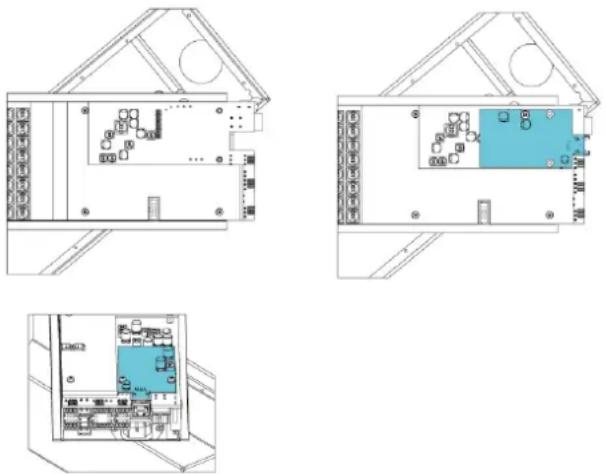
Figure 4.6: Installation of the CobraNet® module

Notice!
Note that this manual does NOT cover the configuration and operation of the CobraNet® module. A description of CobraNet® can be found on www.cobranet.info. Here also CobraNet® Discovery can be downloaded. This is the tool to discover and configure CobraNet® interfaces, including the VARI CobraNet® module.
4.5
Mechanical installation
4.5.1
Mounting height
Mounting a VARI loudspeaker is a straightforward procedure. However, it is extremely important that the height of the unit above floor level is exactly the same as the “Mounting height” dimension entered in the VariControl software. The software optimises VARI’s performance for that specific height and the loudspeaker’s acoustical coverage will be degraded if it is not adhered to. The mounting height used in the creation of the configuration file should be the vertical distance from the floor to the bottom of the VARI base unit. Mark the wall at the mounting location to indicate this height, and also mark the vertical centreline of the loudspeaker to aid drilling the holes for the mounting brackets.
The configuration software allows the bottom of the base unit to be between 0 and 3.5 m above ear level. If the intended ear level is e.g. 1.7 m for people standing, the bottom of the base unit must be at a height of 1.7 to 5.3 m above the floor. VARI units must only ever be installed with the base unit's connector bay at the bottom of the assembly, never upside down.

Figure 4.7: Mounting height
4.5.2
Flush mounting
The VARI loudspeakers use the front side (behind the grille) as heatsink for the amplifiers. This keeps heat radiation at the rear and sides at a minimum and allows for flush mounting into walls. Nevertheless a minimum clearance of 5 cm around the loudspeaker should be maintained, except for the rear side where the depth of the mounting brackets is sufficient.
4.5.3
Mounting the loudspeaker
Once any brackets that require repositioning have been moved and refixed, the loudspeaker is ready for mounting in position. The brackets allow the VARI to be mounted on a flat wall or column. The number of brackets required to mount each configuration is as follows:
| Configuration Brackets | |
| VARI base unit only 2 | |
| VARI base + one extension 3 | |
| VARI base + two extensions 4 |

Warning!
Only use the brackets that are supplied with the loudspeakers for loudspeaker mounting. The VARI loudspeakers are heavy and must be securely fixed to a flat vertical surface.
It is important to ensure that all mounting points are in the same vertical plane, to avoid the unit being bent when the screws are tightened. The design of the hinged brackets makes it possible to drill the wall and insert the fixing screws without removing the brackets from the loudspeaker assembly. The elongated shape of the fixing holes allows the screw heads to pass through the rear plate of the bracket and the speaker is then lowered so that the screw shaft sits in the elongation.
Proceed as follows:
- Use the supplied 30 mm hexagon-headed screws, together with the washers and wall plugs to secure the brackets to the wall. The head size of the supplied screws allow the brackets to slide over the heads later on (step 7).
- Refer to the diagram below. Mark on the centreline the position for the lower hole of the bottom bracket, which will be 89 mm above the datum height previously marked (refer to section Mounting height, page 20). The upper hole of the bottom bracket will be 80 mm above this. Mark the other pairs of holes higher up the centreline using the dimensions given in the drawing. Note that the hole spacing for the two holes in each bracket is always 80 mm.
- Mark and drill the holes (8 mm) for the wall plugs.
- Insert the plugs and screws into the holes. Tighten the screws with a spanner, but stop with a few mm of screw shaft visible between the head and the wall.
- Remove the front grille from the VARI base unit by gently lifting the grille at the locations of the 'snap-on' fittings which hold it in place. Unscrew the six self-tapping screws securing the connector compartment cover and remove the cover.
- If flexible steel (or plastic, nylon, etc.) conduit is to be used to contain the cabling to the rear of the loudspeaker, a conduit fitting or entry bush of the correct size for the conduit should now be fitted to the 37 mm diameter hole in the rear of the connector compartment.
- Open the hinges on all the mounting brackets. Lift the VARI loudspeaker into position and slide the brackets over the heads of the hex-head screws protruding from the wall, at the same time threading all cabling through the rear cable hole (with or without its bush) and the connector compartment so that it is free and accessible from the front.
- Gently lower the VARI so that all fixing screws are fully engaged in the vertical elongations of their bracket holes. Firmly tighten all the screws. Close the hinged brackets so that the loudspeaker is in its correct orientation. Re-check the verticality with a spirit level or similar levelling device.
Figure 4.8: Mechanical dimensions in mm
5
Connector and wiring details
All VARI input and output connectors are located in the connector compartment at the bottom of the VARI-B or VARI-BH base unit. The IEC AC mains socket is immediately adjacent.
Except for the mains connection, all other connections to the VARI base unit are made via Phoenix-type screw-terminal connectors. All mating connectors are supplied; note that three different sizes are used. All connectors on the VARI have male contacts.
The pinouts of each connector are given in the next paragraphs.

Figure 5.1: Base unit connectors

Figure 5.2: Base unit connector overview
| Reference | Connector Reference Connector | ||
| 1 AC mains input 7 Input 2 (100 V) | |||
| 2 Backup DC | power supply input 8 RS-485 network input | ||
| 3 Fuse (for 24 V input only) 9 RS-485 network | thru | ||
| 4 Input 1 (line level) 10 External control input | |||
| 5 Input 2 (line level) 11 Failure relay | |||
| 6 Input 1 (100 V) 12 CobraNet®/Ethernet port | * | ||
* Only present if CobraNet® module is fitted.
5.1
AC Mains input (1)
The VARI base unit is equipped with a 3-pin IEC AC mains connector. The power supply assembly has an internal mains fuse and is not user-accessible. Mains fuse replacement should only be performed by qualified personnel. For ease of installation, the VARI base unit is delivered with a rewireable angled IEC mains power cable connector. Only this connector may be used and should be fitted to a power cord of the required length, having a wire size of 3 x 1 mm² (18 AWG). The power cord should be compliant with the applicable national electrical installation regulations and directives.

Warning!
Only qualified service personnel are allowed to assemble the mains connection.
The VARI base units are Class 1 devices. These units have their chassis connected to the earth pin of the IEC mains connector. This pin must be connected to the electrical earth/ground. A fault in the VARI unit which causes a live conductor to contact the casing will cause a current to flow in the earth conductor. This current should trip either an externally installed overcurrent device (fuse or circuit breaker) or a residual current circuit breaker (ground fault circuit interrupter) which will cut off the supply of electricity to the appliance. Because the IEC mains connector of the VARI base unit is not readily accessible to disconnect the unit when necessary, the mains connection to the VARI base unit should incorporate a manual circuit breaker or an accessible mains plug.
Wire the connector as shown in the table:
| Term Europe USA | |
| L Brown Black | |
| N Blue White | |
| E Green/Yellow Green |
Please use the two supplied cable ties as a strain relief.
First, secure one cable tie around the cable itself. Secondly, secure the cable to the tie mount with the second cable tie, so that the first tie is at the side of the connector.
Now lateral movement is restricted so that no strain can be placed on the connector.
5.2
Backup DC power supply input (2)
Connector type: 2-pole, 7.62 mm-pitch:
| Pin Function | |
| 1 +24 V | |
| 20 V |

Warning!
Because the DC power supply current can be quite high, a minimum wire size of 2.5 mm², or AWG12 must be used.
5.3 Line level input 1 (4) and 2 (5)
The VARI is fitted with two transformer-balanced line inputs. Selection of Input 1 or Input 2 as audio source is made from the VariControl software via the network, and for many installations only Input 1 need be wired. However, Input 2 may be connected to a secondary signal path (in case of a failure elsewhere in the system), or to an emergency sound source. For optimum results only use good quality balanced audio cable consisting of a twisted pair and an overall screen. The audio source(s) should have a low impedance balanced output. The nominal line input level is 0 dBV.
Connector type: 3-pole, 3.81 mm-pitch:
| Input 1 Input 2 | |||
| Pin Function | Pin Function | ||
| 4 Hot (+) 1 Hot (+) | |||
| 5 Ground 2 Ground | |||
| 6 Cold (-) 3 Cold (-) | |||
5.4 100 V input 1 (6) and 2 (7)
These inputs should only be used if the VARI is to be fed from an audio power amplifier with 100 V line outputs (or from an amplifier with low-impedance outputs, via 100 V line transformers). The VARI can thus form part of a 100 V line loudspeaker system and be connected in the same way as the other speakers. Do not connect a 100 V line to input 1 if already a line level input is connected to input 1. Idem for input 2
The inputs are transformer-coupled for impedance matching and galvanic isolation. Selection of Input 1 or Input 2 as audio source is made from the VariControl software via the network, and for most installations only Input 1 need be wired. However, Input 2 may be connected to a secondary signal path (in case of a failure elsewhere in the system), or to an emergency sound source.
Connector type: 2-pole, 5.08 mm-pitch:
| Input 1 | Input 2 | ||
| Pin Function | Pin Function | ||
| 3 100 V line + | 1 100 V line + | ||
| 4 100 V line - | 2 100 V line - | ||
Loudspeaker distribution systems in some territories use 70 V line as the standard; all references in the manual to “100 V line” can be taken as applying equally to 70 V line.
5.5 RS-485 network in (8) and thru (9)
See also
- RS-485 network, page 14
5.5.1 Network configuration
The RS-485 network connection should be wired if the VARI is to be continuously monitored during operation or to be used for commissioning a large system.
The RS-485 interface permits multiple VARI line arrays to be “daisy-chained” in parallel, so that all units are controlled and monitored by the same PC. Two RS-485 connectors (“in” and “thru”) are provided on each VARI to permit such interconnections to be made easily. In such a system, each VARI must have its own unique network address; this will be determined via the VariControl software for each individual line array when the configuration file is loaded. If only one VARI unit is to be connected to the RS-485 network, the “thru” connector (9) can be ignored.
The pinout of the two RS-485 connectors is identical. They should be wired as shown in the table and diagram below, using cable with two separate twisted pairs with individual screens. Connector type: 5-pole, 3.81 mm-pitch:
| RS-485 in | RS-485 thru | ||
| Pin Function | Pin Function | ||
| 1 Ground 6 Ground | |||
| 2 Data Tx+ (Y) | 7 Data Tx+ (Y) | ||
| 3 Data Tx- (Z) | 8 Data Tx- (Z) | ||
| 4 Data Rx- (B) | 9 Data Rx- (B) | ||
| 5 Data Rx+ (A) | 10 Data Rx+ (A) | ||
Because the VARI uses a full duplex RS485 interconnection, it requires a 5-wire interface, consisting of a differential input port (AB), a differential output port (YZ), and a dedicated network ground terminal (Ground). Therefore, the transmit (Tx) and receive (Rx) balanced data lines must be wired via their own twisted pairs.
![graph TD subgraph_Slave_3["slave 3"] A1["A"] --> Ground1["Ground"] B1["B"] --> Ground1 Y1["Y"] --> Ground1 Z1["Z"] --> Ground1 end subgraph_Slave_2["slave 2"] A2["A"] --> Ground2["Ground"] B2["B"] --> Ground2 Y2["Y"] --> Ground2 Z2["Z"] --> Ground2 end subgraph_Slave_1["slave 1"] A3["A"] --> Ground3…](/content/2026/05/1055015/images/e6fda3658e95b23ba1a564777631ecd935ed2b42e07d8b540a1dada6fc2d3c57.jpg)
Figure 5.3: Structure of the RS-485 network
A network is composed of one master device and one or more slave devices. A master device can be a PC running the VariControl software and a USB to RS-485 converter, part of the VARI-CS Configuration Set. All slave devices are wired in parallel, and the master device is connected with the AB and YZ terminals interchanged (see previous figure). Because all slave devices share the same bus, the outputs (YZ) of these units are only enabled during transmission of data from the unit to the master. The implemented network protocol sets the output of all other units in a high impedance state during this period to prevent conflicts.
5.5.2
Cable length
The maximum cable length over which the network connection will operate reliably depends on the cable type and the baud rate used. With good quality cable, a safe maximum figure is 2000 m. If the distance is significantly longer than this, a network repeater will be required. Refer to section RS-485 network, page 14.
5.5.3
Cable termination
According to the official RS-485 standard, the network should be terminated with 120 ohm resistors at both ends of each pair, while the length of the stub lines should not exceed 7 m. The RS-485 transceivers, which are implemented in the VARI, are slew rate limited which minimizes reflections from open cable lengths. This fact, in combination with the relative low baud-rate, makes the network very tolerant to stub lengths or improper termination. Star-wiring of multiple VARI slaves to the master should be avoided. If star-wiring is needed, use a multi-port full duplex hub or multiple full duplex RS-485 repeaters.
5.6 External control input (10)
The VARI's internal memory has provision for an “emergency” configuration preset (Preset 7 by default) to be stored, and automatically recalled and loaded under certain programmable conditions. This is a useful facility where the VARIs are being used as part of an emergency evacuation system. (See VariControl “Help files” for more information on Presets.) The emergency preset may also be recalled by an external DC voltage at the External control input. The External control input is isolated by an opto-coupler. The emergency preset will be loaded either on a logic high (5 – 24 VDC) or a logic low (2 VDC) at the input (programmable in VariControl).
Connector type: 3-pole, 3.81 mm-pitch:
| Pin | Function |
| 4 n/c | |
| 5 + VDC | |
| 6 - VDC |
5.7 Failure relay (11)
If continuous monitoring of the VARI via the RS-485 network is not implemented, a simple monitoring function can be realized with the Failure relay. This has two NC (Normally-Closed) contacts, which open when a fault condition arises. The definition of “fault condition” in this context is programmed by the VariControl software when the unit is configured (see VariControl “Help files” for more information). One set of contacts is fitted with internal resistors to permit impedance-sensing fault-monitoring equipment (such as the supervised control inputs of Bosch Praesideo units) to be interfaced. Note that one side of each contact set is paralleled and brought out as the ‘C’ pin of the external connector.
| Pin 3 > Pin 1 Pin 2 | > Pin 1 | |
| Normal operation Short-circuit 10 kohm | ||
| Fault condition Open-circuit 20 kohm | ||
Connector type: 3-pole, 3.81 mm-pitch:
| Pin | Function |
| 1 | C |
| 2 NC | (impedance-sensing) |
| 3 NC | (hard switching) |
6
Configuring the VARI
This section describes how to use the VariControl software (supplied with the VARI-CS Configuration Set) to create a data file - the configuration file - specific to the loudspeaker being installed.
The electronics section within the VARI base unit is very sophisticated and controls all aspects of the VARI unit's operation. The configuration file which is created in VariControl and uploaded to the line array not only specifies how the unit will perform acoustically, e.g., volume, coverage angles, equalisation, etc., but also incorporates data specifying how the unit should operate under certain emergency conditions, what circumstances constitute a "reportable" failure, and so on. VariControl requires the installer to enter various dimensional data concerning the loudspeaker's location and its intended area of coverage. The file subsequently created is then uploaded from the PC to the loudspeaker via the RS-485 network connection.

Notice!
If the VariControl software has already been installed on the PC and licensed, section Installation of VariControl software on a PC, page 30 can be skipped.
6.1
Installation of VariControl software on a PC
These notes describe how to install the VariControl software application on a PC running Windows. If the user is unfamiliar with VariControl he/she is strongly advised, after installing the application, to study the various "Help files" before attempting to use any of its functions beyond the basic unit configuration described elsewhere in this manual.
6.1.1
Minimum PC requirements
| Processor/Storage Pentium III, 1 GHz, 256 MB RAM, 500 MB (min.) of free disk space. |
| Operating System Windows 2000, XP, Vista, Windows 7 or Windows 8. |
| Ports One free USB port. |
6.1.2
Administrator
The installation and registration of VariControl requires Administrator rights. It is possible to run VariControl as a user with limited access rights. VariControl requires GDI+ to be installed (gdiplus.dll). If you are using a system with Windows 2000, GDI+ might not be installed by default on your system. Normally the installer will take care of this, however a separate GDI+ distribution can be obtained from:
http://www.microsoft.com/downloads/details.aspx?FamilyID=6A63AB9C-DF12-4D41-933C-BE590FEAA05A&displaylang=en
6.1.3
Software installation
To install VariControl, insert the CD-ROM in the PC's disk drive. The InstallShield Wizard will be launched automatically and the welcome screen will be displayed:

Figure 6.1: Welcome screen VariControl InstallShield Wizard
Follow the instructions of the InstallShield Wizard. The installation requires accepting the terms in the license agreement. Also, Readme information is displayed, showing installation notes, folder locations, etc. This information is mainly of relevance to experienced users who already have an earlier version of VariControl installed on the same machine. After finishing installation of the VariControl software and before launching the program, also the VARI DDA libraries should be installed, containing the directivity data for all VARI array configurations. There are two setup executables for the VARI: the first one installs the data for the VARI-B, VARI-B+E, and VARI-B+E+E. The second setup executable installs the data for the VARI-BH, VARI-BH+E, and VARI-BH+E+E. These libraries are installed as programs to be able to manage the default destination folders of the libraries and automatically clean up old libraries in case of updates. During installation it is advised to use the default destination folder ([Program files folder]\Bosch\DDA libraries); if another folder is specified during the installation, the VariControl Folder for DDA libraries should be adapted.

Notice!
Please be patient during installation of the DDA libraries. These libraries are very big and contain thousands of folders and files. Depending on the type of PC, installation may take several minutes.
To remove a library from the PC, use the Add or Remove Programs tool from the Windows Control Panel.
6.1.4
Licensing and evaluation mode
VariControl is a licensed product. Each individual user, company, agency, or institution that uses this program has to obtain a license, one for each computer on which the program is used. After installation, VariControl initially operates in EVALUATION mode. For VariControl version 2.45 or lower, in this mode the software is fully functional with the limitation that the on-line mode is not supported, i.e., the communication port(s) cannot send or receive control data. For VariControl version 2.70 or higher, the EVALUATION mode is fully functional, only at program start-up the license window will appear showing the Days left period until the program will be LOCKED. This period is initially 30 days, and the program should be licensed within this time frame.
Licensing procedure
- Launch the VariControl program. Initially, VariControl operates in EVALUATION mode, and a license window will always appear on program start-up.

Figure 6.2: License window
- Click the Continue>> button in order to start evaluating the program. Evaluation is possible for a limited number of days (indicated in the Days left field of the license window).
- In order to start using the program in on-line mode, a valid Activation code (i.e., 'unlocking' code) must be entered. This code can be obtained by clicking the Activation button on the license window (Internet connection is required). Follow the instructions shown in the web browser in order to obtain this code. The Site code and MID that are shown in the license window are required during registration. If you are not yet a registered user of VariControl, first press the Register link on the Login page to go to the User Registration page. A valid and accessible email address is required for registration.

Login webpage User Registration webpage
▶ After finishing registration, it is possible to enter the VariControl Activation Center using the registered email address and password.

VariControl Activation Center VariControl Activation Code
Using the Site code and MID code (which is PC specific), an Activation code is returned.
Tick the Unlock application radio button in the VariControl license window, then enter (copy-paste) the Activation code in the Activation code field.

Figure 6.3: License window
After pressing the Continue>> button, the application will now start with the evaluation mode limitation removed. Next time the program is started, the license window will not appear anymore. There is no need to store the Site code, MID (Machine ID), and Activation code to extend the license or to move the license to another PC in the future. The Site code and MID will be generated by VariControl, and the Activation code by the license website.
In order to force the license window to appear after registering, activate 'Scroll lock' or 'Caps lock' (with the 'Scroll lock' respectively 'Caps lock' key) before program start-up. This might be required if the license has to be removed. It can also be helpful to show the license status (e.g. Days left). During program execution, the license status can also be found in the About box (select Help | About... from VariControl's main menu). The license is valid for a limited time (180 days by default). The license window will appear on program start-up if the license is expired or will expire within 7 days or less. After license expiration, for VariControl version 2.45 or older, the application will be LOCKED. Click the Activation button in order to re-activate the program. For VariControl version 2.70 or higher, upon the first program start-up after license expiration, the application will fall back into the EVALUATION mode and VariControl can still be used for 30 days before the application will be LOCKED.
License site access
Direct browser access to the registration site is also possible via the general license website of Bosch Security Systems: https://license.boschsecurity.com. Select the Vari-directional Array by clicking on the photo, then the Login webpage will be presented.

Figure 6.4: Bosch Security System license website
6.1.5
Upgrading
Registered users can download the latest version of the VariControl software from the VariControl Activation Center. From here it is also possible to move a license to another PC. When upgrading from a previous version of VariControl, it is advised to backup the files in the Settings, DDA, Scenes and OffLine sub-folders of the installation folder as well as the data folder (if present). Any changes that were made to the contents of the default files present in these folders will be lost, those files will be overwritten during the installation process. The default installation folder is: [Program files folder]\BOSCH\VariControl User The default data folder is: [My documents]\BOSCH\VariControl This data folder is created and populated with files from the installation folder during initial program execution of VariControl.
6.2
Connecting the PC to the VARI
The PC running VariControl software should be connected to the VARI base unit using the USB to RS-485 interface and cables supplied with the VARI-CS Configuration Set. If the front grille of the VARI base unit has not already been removed to attach an extension unit, remove it now with the grille removal tool. Remove the six self-tapping screws securing the connector compartment cover panel and lift the cover off. See Connector and wiring details, page 24. The interface has two connectors. One is a USB connector which is connected to a USB port on the PC using the short USB cable supplied. The other is a 5-pin Phoenix connector which should be connected to the RS-485 Network Connection input on the VARI base unit (refer to section RS-485 network in (8) and thru (9), page 27) using the 5 m-long Phoenix to Phoenix cable also supplied. The VARI loudspeaker will need to be powered for the configuration procedure to be carried out, so connect it to an AC mains supply before proceeding.
USB-to-RS485 converter
Figure 6.5: USB-to-RS485 converter
The USB-to-RS485 converter of the VARI-CS contains an IC device from Future Technology Devices International Ltd. Driver software for this converter can be downloaded from: http://www.ftdichip.com/Drivers/VCP.htm
6.3
Entering the venue parameters
Having connected the PC to the VARI, start the VariControl application. A pop-up appears to select between off-line operation or on-line operation. Select on-line operation by deselecting the off-line mode and select the communication port to which the converter is connected. If a CobraNet® module has been installed, the CobraNet® serial bridge can be selected as communication port for configuration via Ethernet.

Figure 6.6: VariControl Communication options
VariControl auto-detects the VARI configuration to which it is connected, and the precise appearance of the opening screen will reflect the particular model(s). By double-clicking a particular unit in the Network view, the individual settings of that unit are shown and can be changed. Following an example is shown (in off-line mode) for the VARI-B.

Figure 6.7: Entering the venue parameters
6.4
VARI configuration procedure
The red rectangle represents the line array: a base unit only, or a base unit with one or two extension units attached. Next open the Control parameters window by clicking on the icon for the VARI configuration being installed.
6.4.1
Control parameters
The Control Parameters window has eight pages (selected by the top tab set); only the first, Beam, is required for setting the primary system parameters. Ensure that the Geometry tab at the bottom of the window is selected.
![Control parameters [Normal preset 0] / Normal preset 0 Beam Input Volume Delay EQ AVC Surveillance Other Geometry Mount. Height VAR1B Mounting Height (2.1 m) Rat level (1.7 m) Ras (0.6 m) End (20 m) Start End Rac Accr. Res. Coverage SPL Copy PASO opt Re... Beam DSA source file that is installed in t…](/content/2026/05/1055015/images/886f871667ebe5e17fd26b869eac0cbb6d5da77558af6916f67da9e28835d499.jpg)
Figure 6.8: Geometry and Results panes
The five Geometry settings in the top pane represent the physical dimensions relating to the VARI's installed position. The parameter values are simply entered by moving the on-screen slider controls. The ranges of available adjustment for some parameters varies with the loudspeaker configuration and are given in section Ranges of adjustment, page 39. The Results display in the bottom pane shows the predicted performance of the VARI array, and changes in real time to reflect the values of the physical parameters. Two versions of the Results display are available, selected by the two buttons above the diagram. Coverage shows an on-axis, vertical cross-section through the sound field ('On-axis' means that the cross-section is perpendicular to the vertical centre line of the array.). The loudspeaker position is on the left-hand vertical axis, the vertical line represents the vertical position of the loudspeaker (with the '0'-reference at ear level on the start position!) and the horizontal line the coverage zone, between Start and End distances. The predicted sound field in front of the array is colour-coded to show SPL (Sound Pressure Level), with a key relating colour to dBs on the right. The thin straight line superimposed on the coverage plot indicates the ear level as specified by the currently-set parameter values. Right-clicking in the window pops-up a selection box that allows to select a plot and copy it to the Windows clipboard, e.g. to paste it into a word-processing file for project documentation. The five parameters to have their values entered are defined in the next table:
| Mounting height | This is the mounting height of the loudspeaker, and is measured vertically from floor level to the bottom of the base unit. The height is selectable in increments of 0.1 m. |
| Start This is | the horizontal distance from the front of the loudspeaker to the position at which defined coverage is required, which will normally be the first audience row. The distance is selectable in increments of 1 m. Select the value closest to that applicable to the venue. |
| End This is | the horizontal distance from the front of the loudspeaker to the furthest position at which defined coverage is required. This will normally be the last audience row. The range available varies with the array type because adding an extension unit to a base unit increases the effective coverage distance of the array. The distance is selectable in increments of 1 m. Select the value closest to that applicable to the venue.In case of a hard (acoustically reflective) wall just behind the last row, the contribution of the back wall echo may be reduced by using a smaller value for the End parameter. |
| Rise This should be left at 0.0 m if the audience area is horizontal. Many venues use raked seating, however, and if this is the case, the height of the last row of the seating should be entered here. Rise is adjustable in increments of 0.1 m. | |
| Ear level (Listening height) | The height of the audience's ears above floor level will be greater in a standing venue than one with seats, and this parameter may be adjusted to allow for this. (It may also be appropriate to adjust this to allow for audiences predominantly comprising children!) The parameter is adjustable in increments of 0.1 m. |
6.4.2
Ranges of adjustment
| Parameter VARI-B/BH VARI-B/BH+E VARI-B/BH+E+E | |||
| Mounting Height* 0.5 m - 4.0 m (min. Ear level) / 2.0 m - 5.5 m (max. Ear level) | |||
| Start 1.0 m - 5.0 m | |||
| End 10.0 m - 20.0 m 10.0 m - 32.0 m 10.0 m - 50.0 m | |||
| Rise** 0.0 m - 3.4 m 0.0 m - 5.3 m 0.0 m - 7.9 m | |||
| Listening Height (Ear level) 0.5 m - 2.0 m | |||
* The Mounting height range is dependent on the setting of the Ear level parameter. ** Maximum value of Rise is dependent on setting of End parameter and is limited by the maximum angle of the slope, which is 10 degrees. Figure given is with End at maximum.
The alternative SPL display shows the same computed data as a simple graph of SPL at ear level against distance.
6.4.3
Other VARI parameters
The Help files supplied with VariControl software are quite extensive, and installers are referred to these for detailed information on other aspects of the configuration program. The Help button in the Control Parameters window itself is context-sensitive. For completeness, however, a brief description of the facilities available on the other pages of the Control Parameters window is given below, accessible by tab selection:
- Input: Comprises five tabs (at bottom), giving control over input selection and input signal processing.
- Common parameters: Selection of active input, method of priority switching and setting of switching parameters.
- Gain/delay [In-1]: Adjustment of input gain and delay (in milliseconds or metres), phase inversion, priority setting and enabling of pilot tone detection for Input 1. Input and output levels can be monitored by selecting Tools | Status properties (F5) | Levels.
- EQ [In-1]: Each input has a 4-band equalisation available, with a choice of fully-parametric hi-pass, low-pass, notch, bell or shelving filters in each band.
- Gain/delay [In-2]: As for Input 1.
- EQ [In-2]: As for Input 1.
- Volume: Provides adjustment of overall unit volume. Controls for setting gain in the analog domain both before (Analog pre-gain) and after (Analog output gain) the DSP section are included. Volume reduction under ducking control is also set here.
- Delay: Allows an overall pre-delay to be added (is applied to both input channels).
- EQ: In addition to the per-input EQ, an 8-band equalisation curve may be set to tailor the overall frequency response of the loudspeaker.
- AVC: This feature enables the VARI to automatically increase the amplifier gain (and hence the volume) as the ambient noise in the venue increases. To achieve this, the VARI is fitted with an ANS (Ambient Noise Sensing) microphone, and the embedded AVC (Automatic Volume Control) algorithm is able to measure the ambient noise during gaps in the programme material or between announcements.
- Surveillance: This page permits configuration settings relating to the loudspeaker's operation under various fault conditions to be made.
- Other: Miscellaneous unit settings.
6.4.4
Applying and saving the settings
When all the venue parameters have been entered, click the Apply button. This will transfer the settings to the VARI unit.
To save the settings as a file on the PC, proceed as follows:
Click Save... to open the Save control parameters settings window.

Figure 6.9: Save control parameters settings
- Note that it is possible to save a subset of the speaker's parameters, as well as the whole set. If all the parameters are to be saved, ensure that all the checkboxes in the Parameters pane are ticked.
- Unless you have reason to do otherwise (see the Help files), ensure that Current preset only is selected in the Preset options box in the Presets pane.
- The File name box in the Settings file pane specifies the location in which the settings file will be saved. The default folder is at C:...\My Documents\Bosch\VariControl\Settings, and the default filename is vari_default.ini. Installers will generally wish to save the settings file(s) in a different location; clicking on the folder symbol to the right of the File name box will open a standard Save As window. Navigate to the desired location and give the file a name; Click Save. Note that VARI settings files have a *.ini filename extension.
- Click OK.
- If the filename in the File name box has not been changed, a Warning dialogue box appears asking for confirmation that the existing file should be overwritten. Click Yes if this is the case.
- An Info dialogue box appears, confirming the file saving details. Click OK if everything is correct.
- Proceed with section Mechanical installation, page 20 in case the VARI is not mechanically mounted yet.
6.4.5
Loading a previously saved settings file
It may be appropriate for multiple VARI speakers in an installation to have exactly the same settings. In this case, a settings file, saved according to the procedure outlined above, may be loaded into VariControl and then transferred to further loudspeakers.
Loading an *.ini file is straightforward and similar to the procedure for saving. From the Control parameters window:
- Click Load..., to open the Load control parameters settings window.
- Note that it is possible to load a subset of the loudspeaker's parameters, as well as the whole set. If all the parameters are to be loaded, ensure that all the checkboxes in the Parameters pane are ticked.
- Unless you have reason to do otherwise (see the Help files), ensure that Current preset only is selected in the Preset options box in the Presets pane.
- The File name box in the Settings file pane specifies the location of the settings file to be loaded. Clicking on the folder symbol to the right of the File name box will open a standard Open window. Navigate to the folder containing the desired file; click on the file and then click Open.
- Click OK. An Info dialogue box appears, confirming the file saving details. Click OK if everything is correct. The settings file will be uploaded into the VARI speaker, and into VariControl so that the parameters are visible.
- Proceed with section Mechanical installation, page 20 in case the VARI is not mechanically mounted yet.
7

Technical Data
Notice!
The provided technical data for the VARI-B, VARI-BH and VARI-E is also valid for the white versions VARI-BL, VARI-BHL and VARI-EL, except for the color specification.
Acoustical
| Frequency range 2 | |
| VARI-B 130 Hz to 10 kHz ( ± 3 dB) | |
| VARI-BH 130 Hz to 18 kHz ( ± 3 dB) |
| Max SPL 3 | Continuous / peak |
| VARI-B 90 / 93 dB SPL (A-weighed at 20 m) | |
| VARI-B+E 90 / 93 dB SPL (A-weighed at 32 m) | |
| VARI-B+E+E 88 / 91 dB SPL (A-weighed at 50 m) | |
| VARI-BH 89 / 92 dB SPL (A-weighed at 20 m) | |
| VARI-BH+E 89 / 92 dB SPL (A-weighed at 32 m) | |
| VARI-BH+E+E 87 / 90 dB SPL (A-weighed at 50 m) | |
| Coverage | |
| Horizontal (fixed) 4 | 130° (-6 dB, avg. 1 to 4 kHz) |
| Vertical (adjustable) 5 | Software configurable |
| Maximum throw: | |
| VARI-B(H) 20 m | |
| VARI-B(H)+E 32 m | |
| VARI-B(H)+E+E 50 m |
| Transducers | |
| VARI-B 4” Full Range (8 x 1 driver) | |
| VARI-BH 4” Coaxial (8 x 1 driver) | |
| VARI-E 4” Full Range (4 x 2 drivers) |
Electrical
| Input Line (2x) | |
| Input level nominal 0 dBV rms | |
| Input level maximum +20 dBV peak | |
| Type Transformer balanced | |
| Impedance (balanced) 7.8 kohm at 1 kHz | |
| Input 100 V (2x) | |
| Input level nominal +40 dBV rms | |
| Type Transformer balanced (floating input) | |
| Impedance (balanced) 1 Mohm at 1 kHz | |
| Power Amplifiers | |
| Power | |
| VARI-B(H) 8 x 15 W (class-D full bridge) | |
| VARI-E 4 x 25 W (class-D full bridge) | |
| Protection Thermal shutdown | |
| Current limiting | |
| Dynamic range 6 | >105 dB |
| PSU | |
| Mains voltage 100 to 120 V / 200 to 24 V (auto switching) | |
| Power consumption @ Mains / 24 Vdo | |
| Power save | |
| VARI-B(H) 13 / 4.5 W | |
| VARI-B(H)+E | 17 / 7 W |
| VARI-B(H)+E+E | 19 / 9 W |
| Idle | |
| VARI-B(H) 18 / 8.5 W | |
| VARI-B(H)+E | 23 / 13 W |
| VARI-B(H)+E+E | 28 / 17 W |
| Max. (Noise, CF 6 dB) | |
| VARI-B(H) 60 / 36 W | |
| VARI-B(H)+E | 97 / 75 W |
| VARI-B(H)+E+E | 124 / 100 W |
| Power factor | According to EN61000-3-2, class A |
| Mains inrush current <70 A (at 230 V) | |
| Protection Thermal shutdown | |
| Current limiting | |
| Under voltage lock-out | |
| Signal processing 5 | |
| DSP 32-bit floating point, 900 Mflops | |
| ADC / DAC 24-bits S-D, 128 x oversampling | |
| Sample rate 48 kHz | |
| Functions Pre-delay (max. 21 s) | |
| Input-delay (max. 2 x 10 s / 4 x 5 s) | |
| Equalizer and compensation filtering | |
| Compressor | |
| Volume | |
| AVC |
| Control | |
| Network interface RS-485 full duplex, auto-switching 115k2, 57k6, 38k4, 19k2 baud, optically isolated | |
| Max. number of units 7 | 126 |
| Surveillance General status | |
| Amplifier and load monitoring | |
| External pilot-tone detection | (20 kHz to 30 kHz, min. level -22 dBV) |
| Built-in ambient noise sensing microphone | |
| Thermal overload protection | |
| Failure relay Maskable conditions | |
| Contact 1 No failure = closed / Failure = open | |
| Rating Max. 24 V, 100 mA | |
| Contact 2 No failure = 10 k ohm / Failure = 20 k ohm | |
| Control voltage input 5 to 24 Vdc, optically isolated | |
| CobraNet | |
| Interface RJ-45, Ethernet 100 Mbps |
| Word length 16-/20-/24-bit (set by transmitter) |
| Sample rate 48 kHz |
| Additional latency 1.33/2.67/5.33 ms (set by transmitter) |
Mechanical
| Dimensions (H x W x D) | |
| VARI-B(H) 1200 x 130 x 98 mm | (47.2 x 5.1 x 3.8 in) |
| VARI-B(H)+E 2400 x 130 x 98 mm | (94.5 x 5.1 x 3.8 in) |
| VARI-B(H)+E+E 3600 x 130 x 98 mm | (141.7 x 5.1 x 3.8 in) |
| Bracket 27 mm (1.1 in) additional depth, flat mounted | |
| VARI-CM 100 x 50 x 23 mm | (3.9 x 2.0 x 0.9 in) |
| Weight | |
| VARI-B(H) 13.0 kg (28.7 lbs) | |
| VARI-B(H)+E 24.7 kg (54.5 lbs) | |
| VARI-B(H)+E+E 36.4 kg (80.3 lbs) | |
| Color | |
| Enclosure:VARI-B(H) and -EVARI-B(H)L and -EL | RAL9007 (gray aluminum)RAL9003 (signal white) |
| Grill:VARI-B(H) and -EVARI-B(H)L and -EL | RAL9006 (white aluminum)RAL9003 (signal white) |
Environmental
| Operating temperature | -25 °C to 55 °C (-13 °F to 131 °F) |
| Storage temperature -40 °C to +70 °C | (-40 °F to +158 °F) |
| Relative humidity <95 % |
Certifications and approvals
| Safety according to IEC 60065: 2001 + A1: 2005 | |
| Immunity according to EN 55103-2: 2009 | according to FCC-47 part 15B |
| Emissions according to EN 55103-1: 2009 | according to EN 50130-4: 2006according to EN 50121-4: 2006according to EN 61000-3-2:2006 + A1: 2009 + A2: 2009 |
| Wind-force according to NEN 6702: 2007 + A1: | 2008,Bft 11 |
| Water and dust protection according to EN605 | 29 IP54 |
| Approval CE |
Notes:
- Measured outside under semi-anechoic 'full-space' conditions with typical filter and delay settings unless stated otherwise.
- Measured on-axis. The frequency response of the complete array is depending on the actual signal processing parameters and air absorption (at larger distances). A typical bandwidth is specified for the complete array under 'full-space' radiation conditions.
- Levels are valid for pink noise (100 Hz to 20 kHz bandwidth) with a crest factor of 3 dB, default EQ and minimum opening angle setting. 'Continuous' is the RMS level, 'Peak' is the absolute peak level, both determined at the onset of the output limiter. SPL values will vary depending upon opening angle.
- For this measurement the signals at all power amplifier outputs are summed together.
- Additional processing capabilities available.
- Measured as the A-weighted difference (in dB) between the maximum rms level (with pink noise input signal) and the noise output (with no input signal present).
- Maximum number that can be connected to one RS-485 subnet, multiple subnets can be controlled by one host PC.
Bosch Security Systems B.V.
Torenallee 49
5617 BA Eindhoven
The Netherlands
www.boschsecurity.com
© Bosch Security Systems B.V., 2014

- VARI-DIRECTIONAL ARRAY
- BOSCH
- SAFETY
- REFERENCE TO EC STATEMENT OF CONFORMITY
- INTRODUCTION
- NOTICE
- USERS NOTICE AND DISCLAIMER
- INTENDED AUDIENCE
- SYSTEM OVERVIEW
- VARI-XX LINE ARRAYS
- VARI CONFIGURATION SET
- VARI COBRANET® MODULE
- WHAT'S IN THE PACKAGING
- INSTALLATION
- PREPARING FOR INSTALLATION
- MOUNTING LOCATION
- POWER SUPPLY
- WARNING
- POWER, SIGNAL AND CONTROL CABLES
- AC MAINS SUPPLY
- AUDIO INPUTS
- BACKUP DC POWER SUPPLY
- FAILURE RELAY
- CONTROL INPUT
- RS-485 NETWORK
- COBRANET® INPUT
- COMMON ANALOGUE GROUNDING ISSUES
- REDUCTION OF RF EMISSION
- RF IMMUNITY
- ADDING VARI-E EXTENSION UNITS
- ATTACHMENT METHOD
- MOUNTING BRACKETS
- LINE ARRAYS WITH EXTENSION UNITS - REPOSITIONING THE BRACKETS
- REMOVING OF THE FRONT GRILLE
- CONNECT EXTENSION UNIT TO BASE UNIT
- OPTIONAL COBRANET® MODULE
- MECHANICAL INSTALLATION
- MOUNTING HEIGHT
- FLUSH MOUNTING
- MOUNTING THE LOUDSPEAKER
- CONNECTOR AND WIRING DETAILS
- AC MAINS INPUT (1)
- BACKUP DC POWER SUPPLY INPUT (2)
- LINE LEVEL INPUT 1 (4) AND 2 (5)
- V INPUT 1 (6) AND 2 (7)
- RS-485 NETWORK IN (8) AND THRU (9)
- SEE ALSO
- NETWORK CONFIGURATION
- CABLE LENGTH
- CABLE TERMINATION
- EXTERNAL CONTROL INPUT (10)
- FAILURE RELAY (11)
- CONFIGURING THE VARI
- INSTALLATION OF VARICONTROL SOFTWARE ON A PC
- ADMINISTRATOR
- SOFTWARE INSTALLATION
- LICENSING AND EVALUATION MODE
- LICENSING PROCEDURE
- LOGIN WEBPAGE USER REGISTRATION WEBPAGE
- VARICONTROL ACTIVATION CENTER VARICONTROL ACTIVATION CODE
- LICENSE SITE ACCESS
- UPGRADING
- CONNECTING THE PC TO THE VARI
- ENTERING THE VENUE PARAMETERS
- VARI CONFIGURATION PROCEDURE
- CONTROL PARAMETERS
- OTHER VARI PARAMETERS
- APPLYING AND SAVING THE SETTINGS
- LOADING A PREVIOUSLY SAVED SETTINGS FILE
- TECHNICAL DATA
- NOTES
Brand : BOSCH
Model : LA3-Vari-E
Category : Loudspeaker