T10F-22M - Audio Visual Accessory Kramer - Free user manual and instructions
Find the device manual for free T10F-22M Kramer in PDF.


| Product Type | Signal Converter |
| Brand | Kramer |
| Model | T10F-22M |
| Dimensions (W x D x H) | 100 x 75 x 25 mm |
| Weight | 200 g |
| Power Supply | USB-C 5V DC, 1A |
| Power Consumption | 2.5 W max |
| Input Connector | HDMI Type A (female) |
| Output Connector | HDMI Type A (female) |
| Supported Resolution | Up to 4K@60Hz (3840x2160) |
| Supported Audio Formats | LPCM 2.0, Dolby Digital, DTS |
| HDCP Version | 2.2 |
| Operating Temperature | 0°C to 40°C |
| Storage Temperature | -20°C to 60°C |
| Enclosure Material | Aluminum |
| LED Indicators | Power, Signal Status |
| Main Functions | Signal conversion, scaling, EDID management |
| Maintenance & Cleaning | Wipe with a soft, dry cloth; avoid liquids |
| Safety Precautions | Use in dry environment, keep away from moisture |
| Spare Parts & Repairability | Not user-serviceable; contact Kramer support |
| General Information | Professional AV accessory, Kramer brand, 2-year warranty |
Frequently Asked Questions - T10F-22M Kramer
User questions about T10F-22M Kramer
0 question about this device. Answer the ones you know or ask your own.
Ask a new question about this device
Download the instructions for your Audio Visual Accessory in PDF format for free! Find your manual T10F-22M - Kramer and take your electronic device back in hand. On this page are published all the documents necessary for the use of your device. T10F-22M by Kramer.
USER MANUAL T10F-22M Kramer
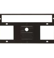
The Kramer T10F-22M Inner Frame
Congratulations on purchasing your Kramer T10F-22M Inner Frame for the TBUS-10XL Table Connection bus.
The T10F-22M Inner Frame includes:
• An opening for 1 SID-X1 or other MegaTOOL
- 1 blank insert
• 2 power socket openings
• 1 pass through insert

Note that you can install the optional T-2INSERT (P/N: 80-00006699) inside a single power socket opening.

natural_image
Black rectangular device with three white panels and a central circular component (no text or symbols)Figure 1: T10F-22M Inner Frame (P/N: 80-000028)
Installing the Wall Plate Inserts
Before installing the inner frame, you need to install wall plate inserts.

Go to http://www.kramerelectronics.com to check for up-to-date user manuals and the complete list of Kramer wall plate inserts and module connectors.
You can rearrange or remove any of the blank inserts mounted on the inner frame and replace them with Kramer wall plate inserts or connector modules for interfacing A/V type signals.
To mount a Kramer insert or connector module:
- Unscrew the two screws that fasten the blank insert to the inner frame and remove the blank insert.
- Place the required Kramer wall plate insert over the opening, insert the two screws to fix the Kramer insert in place, and tighten them.
Installing the SID-X1 or other MegaTOOL
To install the SID-X1, as shown in Figure 2:
- Fasten each of the supplied TOOL brackets to their location (one on each side).
- Insert the SID-X1, from underneath, through the MegaTOOL opening.
- Fasten the screws (one on each side) through the inner frame holes and TOOL brackets.
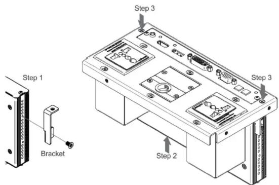
Figure 2: Installing the SID-X1
Installing the Inner Frame
To install the T10F-22M inner frame:
- Place the assembled inner frame inside the TBUS-10XL enclosure.
- Set the required height using your fingers to bring the inner frame to the desired position, and then screw and tighten it in place using the height adjustment screws supplied with the inner frame.
Connecting the Cables
When replacing blank inserts with connector inserts (for example, VGA, audio, HDMI and so on):
- Insert the cables to their appropriate connectors from underneath.
- Secure the cables to the tie holes on the TBUS-10XL. Do not secure the cables too tightly or too loosely. Leave a small amount of slack.
After the TBUS-10XL is connected to mains power and the proper cables, it is ready for use.
Adjusting the Height of the Inner Frame
If needed, you can adjust the inner frame to one of the several possible heights to accommodate large or bulky cables. To adjust, perform the following:
- Remove the height adjustment screws, while supporting the frame from underneath with your fingers.
- Raise or lower the connecting surface to the required height, insert the screws, and tighten them in place.

KRAMER ELECTRONICS LTD.
Installation Instructions
MODEL:
T10F-22M Inner Frame
For the latest information on our products and a list of Kramer distributors, visit our Web site where updates to this user manual may be found.
We welcome your questions, comments, and feedback.
Web site: www.kramerelectronics.com
E-mail: info@kramerel.com


SAFETY WARNING
Disconnect the unit from the power supply before opening and servicing





Brand : Kramer
Model : T10F-22M
Category : Audio Visual Accessory