
ProScale VP-729 - Scale Kramer - Free user manual and instructions
Find the device manual for free ProScale VP-729 Kramer in PDF.


| Product Type | Digital Scale |
| Brand | Kramer |
| Model | ProScale VP-729 |
| Weight Capacity | Up to 500 kg (1100 lb) |
| Readability | 0.1 kg / 0.2 lb |
| Display | Large LCD backlit display |
| Units of Measure | kg / lb / oz / stones |
| Platform Size | 600 x 500 mm (23.6 x 19.7 inches) |
| Platform Material | Stainless steel |
| Power Supply | AC adapter (included) or 6 x AA batteries (not included) |
| Auto-Off | Yes, after 3 minutes of inactivity |
| Tare Function | Yes, subtracts container weight |
| Calibration | External calibration with calibration weight (not included) |
| Hold Function | Yes, holds stable reading |
| Overload Protection | Yes, audible and visual alarm |
| Net Weight | Approximately 4.5 kg (9.9 lb) |
| Dimensions (W x D x H) | 620 x 520 x 90 mm (24.4 x 20.5 x 3.5 inches) |
| Operating Temperature | 0°C to 40°C (32°F to 104°F) |
| Storage Temperature | -10°C to 60°C (14°F to 140°F) |
| Certifications | CE, FCC, OIML (pending) |
| Warranty | 2 years limited |
Frequently Asked Questions - ProScale VP-729 Kramer
User questions about ProScale VP-729 Kramer
0 question about this device. Answer the ones you know or ask your own.
Ask a new question about this device
Download the instructions for your Scale in PDF format for free! Find your manual ProScale VP-729 - Kramer and take your electronic device back in hand. On this page are published all the documents necessary for the use of your device. ProScale VP-729 by Kramer.
USER MANUAL ProScale VP-729 Kramer
Presentation Switcher/Scaler
VP-729 Quick Start Guide
This guide helps you install and use your product for the first time. For more detailed information, go to http://www.kramerelectronics.com/support/product_downloads.asp to download the latest manual or scan the QR code on the left.
Step 1: Check what's in the box
The VP-729 Presentation Switcher Scaler
2 C-SF/2RVM cables
IR remote control transmitter with batteries
1 Null-modem adapter
1 Set of rack ears
4 Rubber feet
1 Power cord
1 Quick start guide
Save the original box and packaging materials in case you need to return your product for service.
Step 2: Install the VP-729
Mount the machine in a rack or place on a table.
Step 3: Connect inputs and outputs
Always switch OFF the power on each device before connecting it to your VP-729.

flowchart
graph TD
    A["Component DVD Player"] --> B["Composite DVD Player"]
    B --> C["s-Video DVD Player or Set-top box"]
    C --> D["Computer Graphics Source (PC)"]
    D --> E["DVD Player"]
    E --> F["Computer Graphics Source (PC)"]
    F --> G["Power amplifiers"]
    G --> H["PC Control Device"]
    H --> I["Analog Display (screen)"]
    I --> J["Plasma Display or Projector"]
    J --> K["DVD Player (HDMI) or Set-top box"]
    K --> L["Hardware Out"]
    L --> M["Hardware Out"]
    M --> N["Hardware Out"]
    N --> O["Hardware Out"]
    O --> P["Hardware Out"]
    P --> Q["Hardware Out"]
    Q --> R["Hardware Out"]
    R --> S["Hardware Out"]
    S --> T["Hardware Out"]
    T --> U["Hardware Out"]
    U --> V["Hardware Out"]
    V --> W["Hardware Out"]
    W --> X["Hardware Out"]
    X --> Y["Hardware Out"]
    Y --> Z["Hardware Out"]
    Z --> AA["Hardware Out"]
    AA --> AB["Hardware Out"]
    AB --> AC["Hardware Out"]
    AC --> AD["Hardware Out"]
    AD --> AE["Hardware Out"]
    AE --> AF["Hardware Out"]
    AF --> AG["Hardware Out"]
    AG --> AH["Hardware Out"]
    AH --> AI["Hardware Out"]
    AI --> AJ["Hardware Out"]
For best results, we recommend that you always use Kramer high-performance cables to connect AV equipment to the VP-729.
Step 4: Connect the power
Connect AC power to the rear of the VP-729, switch on its power and then switch on the power on each device.

natural_image
Close-up of a black electronic device with a gray power outlet and cable, no visible text or symbolsStep 5: Operate via the front panel buttons and the remote control transmitter
Push the MENU button to access the menu and show the main menu screen on your display or projector.
If you cannot see any images, verify that the output cable to your display, TV, or projector is in good working order and is connected to the VP-729.
If you still don't see an image, press and hold the RESET TO XGA/720P button for a second to reset the output to XGA (1024x768) resolution. Push the MENU button again and the main menu should appear on the screen.
Press an input button. The VP-729 will quickly fade to black, switch inputs, and then fade up from black to show the new input signal on your display or projector.
Press and hold to reset to the default resolution (helpful if you fail to see the input signal on the display)

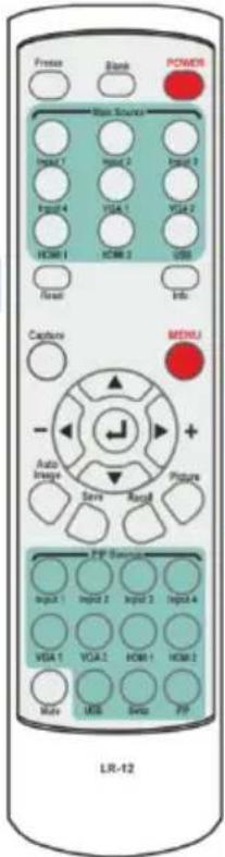
POWER Cycles power

Press one of the nine Main Source buttons to select an input signal

The MENU button shows the main OSD menu. The arrow buttons and ENTER button let you navigate within the OSD menu

Step 6. Set the inputs
Universal Inputs: by default, the UNIVERSAL inputs are set to CV. To change the default setting, select a different input via the Input OSD menu.
UXGA inputs: you do not have to set the UXGA inputs
HDMI Inputs: set HDCP support via the Setup OSD menu
USB Input: read JPEG picture files (up to 2048x1536 and not exceeding 1MB) to use as a logo, background or to create a slideshow
Step 7: Set the output resolution

The VP-729 is set at the factory to a default output resolution of 1024x768 (XGA) with a refresh rate of 60Hz.
If your projector or display uses XGA resolution, you can start using the VP-729. If not, you can set a different output resolution via the Output OSD menu.
Contents
1 Introduction 1
2 Getting Started 2
2.1 Achieving the Best Performance 2
2.2 Recycling Kramer Products 2
3 Overview 3
3.1 Defining the VP-729 Presentation Switcher/Scaler 5
4 Installing in a Rack 8
5 Connecting the VP-729 9
5.1 Connecting a PC 11
5.2 Connecting the VP-729 via the ETHERNET Port 11
6 Presentation Switcher / Scaler Buttons 12
6.1 Switching an Input 12
6.2 The PIP Button Feature 13
6.3 Locking and Unlocking the Front Panel 17
6.4 The Infrared Remote Control Transmitter 18
7 Configuring the VP-729 via the OSD MENU Screens 19
7.1 The Input Screen 20
7.2 The Picture Screen 22
7.3 The Output Screen 23
7.4 The PIP Screen 25
7.5 The Audio Screen 26
7.6 The Geometry Screen 27
7.7 The Setup Screen 28
7.8 The Advanced Setup Screen 30
7.9 The Info Screen 35
8 Using Text Overlay 36
9 Audio Flash Memory Upgrade 38
9.1 Downloading from the Internet 38
9.2 Connecting the PC to the RS-232 Port 39
9.3 Upgrading the Audio Firmware 39
10 Technical Specifications 44
11 VP-729 Communication Protocol 49
11.1 Error Codes Description 60
Figures
Figure 1: VP-729 Presentation Switcher/Scaler Front Panel 6
Figure 2: VP-729 Presentation Switcher/Scaler Rear Panel 7
Figure 3: Connecting to the VP-729 Rear Panel 10
Figure 4: Crossed Cable RS-232 Connection 11
Figure 5: Straight Cable RS-232 Connection with a Null Modem Adapter 11
Figure 6: PIP Source over Background 14
Figure 7: The SWAP Status 15
Figure 8: IR Remote Control Transmitter 18
Figure 9: MENU Items 19
Figure 10: Input Screen 20
Figure 11: Picture Screen 22
Figure 12: Output Screen 23
Figure 13: PIP Screen 25
Figure 14: Audio Screen 26
Figure 15: Geometry Screen 27
Figure 16: Setup Screen 28
Figure 17: Advanced Setup Screen 30
Figure 18: Misc Screen 31
Figure 19: Input Functions 33
Figure 20: Output Functions 34
Figure 21: Active Video Functions 35
Figure 22: Information Screen 35
Figure 23: Text Overlay Application Screen 36
Figure 24: Splash Screen 39
Figure 25: Atmel – Flip Window 40
Figure 26: Device Selection Window 40
Figure 27: Selecting the Device Window 41
Figure 28: Loading the Hex 41
Figure 29: RS-232 Window 42
Figure 30: Atmel – Flip Window (Connected) 42
Figure 31: Atmel – Flip Window (Operation Completed) 43
1 Introduction
Welcome to Kramer Electronics! Since 1981, Kramer Electronics has been providing a world of unique, creative, and affordable solutions to the vast range of problems that confront the video, audio, presentation, and broadcasting professional on a daily basis. In recent years, we have redesigned and upgraded most of our line, making the best even better!
Our 1,000-plus different models now appear in 11 groups that are clearly defined by function: GROUP 1: Distribution Amplifiers; GROUP 2: Switchers and Matrix Switchers; GROUP 3: Control Systems; GROUP 4: Format/Standards Converters; GROUP 5: Range Extenders and Repeaters; GROUP 6: Specialty AV Products; GROUP 7: Scan Converters and Scalers; GROUP 8: Cables and Connectors; GROUP 9: Room Connectivity; GROUP 10: Accessories and Rack Adapters and GROUP 11: Sierra Products.
Congratulations on purchasing your Kramer VP-729 Presentation Switcher / Scaler, which is ideal for the following typical applications:
- Projection systems in conference rooms, boardrooms, auditoriums, hotels and churches, production studios, rental and staging
- Any application where high quality conversion and switching of multiple and different video signals to graphical data signals is required for projection purposes
2 Getting Started
We recommend that you:
- Unpack the equipment carefully and save the original box and packaging materials for possible future shipment
• Review the contents of this user manual
• Use Kramer high performance high resolution cables
• Use only the power cord that is supplied with this machine

Go to http://www.kramerelectronics.com to check for up-to-date user manuals, application programs, and to check if firmware upgrades are available (where appropriate).
2.1 Achieving the Best Performance
To achieve the best performance:
- Use only good quality connection cables to avoid interference, deterioration in signal quality due to poor matching, and elevated noise levels (often associated with low quality cables)
- Do not secure the cables in tight bundles or roll the slack into tight coils
- Avoid interference from neighboring electrical appliances that may adversely influence signal quality
• Position your Kramer VP-729 away from moisture, excessive sunlight and dust
2.2 Recycling Kramer Products
The Waste Electrical and Electronic Equipment (WEEE) Directive 2002/96/EC aims to reduce the amount of WEEE sent for disposal to landfill or incineration by requiring it to be collected and recycled. To comply with the WEEE Directive, Kramer Electronics has made arrangements with the European Advanced Recycling Network (EARN) and will cover any costs of treatment, recycling and recovery of waste Kramer Electronics branded equipment on arrival at the EARN facility. For details of Kramer's recycling arrangements in your particular country go to our recycling pages at http://www.kramerelectronics.com/support/recycling/.
3 Overview
The Kramer VP-729 is a 9-input Proscale™ Presentation Switcher / Scaler with unbalanced stereo and digital S/PDIF audio. The VP-729 scales any composite, s-Video (Y/C), component video (YUV), HDMI or computer graphics video signal, as well as JPEG files (via USB) up or down to a selectable graphics or HDTV output resolution. It also provides glitch-free switching between sources through FTB™ (fade-thru-black) switching technology, in which the video fades to black and then the new input fades from black for glitch-free and smooth switching. The output signal provides constant sync so the display never glitches. The output signal is available simultaneously on a 15-pin HD computer graphics video (UXGA) connector and on an HDMI connector.
The VP-729 features include:
- Silicon Optix HQV® Video Processing - HQV (Hollywood Quality Video) processing represents the state-of-the-art in video processing technology, with the highest quality de-interlacing, noise reduction, and scaling performance for both standard-definition and high-definition signals
- K-IIT XL™ Picture-in-Picture Image Insertion Technology - ultra stable picture-in-picture, picture-and-picture, and split screen capability. Any video source can be inserted into or positioned next to a computer graphics video source or vice versa with window positioning and sizing controls
- Four user definable (universal) video inputs (each can be set as composite video, s-Video (Y/C) or component video), two computer graphics video inputs, two HDMI inputs and 1 USB input (for reading JPEG image files that are recognized up to 2048x1536 and do not exceed 1MB)
• HDTV compatible component input
• HDTV output resolutions - 720p 1080i, and 1080p
• Scaled video outputs - HDMI and computer graphics video - HDMI support of up to 2.25Gbps bandwidth per graphic channel Suitable for resolutions up to UXGA at 60Hz, and for all HD resolutions
- Multiple computer graphics output resolutions - including a user-defined output resolution with selectable refresh rates
• Multiple aspect ratio selections
• Companion AFV (audio-follow-video) for every analog video input
- Embedded audio on the two HDMI inputs and output
The embedded audio feature is not available for the RGB resolutions 1920x1200 and 1920x1080. (It is available for 1080p)
• Built-in noise reduction and picture enhancement features
- Audio inputs - four (stereo audio or S/PDIF on two RCA connectors) for each of the four universal video inputs; two unbalanced stereo audio (on 3.5mm mini jacks) for the two computer graphics video inputs; and embedded audio on the HDMI inputs
- Audio outputs - S/PDIF and unbalanced stereo audio (RCA connectors). The machine transcodes stereo or S/PDIF audio to both stereo and S/PDIF audio and embeds audio into the HDMI output
Tip: To use a 5.1 digital audio source, connect this HDMI or S/PDIF source (for example, a Blu-ray player) directly to your receiver or display
• Built-in Time Base Corrector - stabilizes video sources with unstable sync
- Built-in video Proc-Amp - color, hue, sharpness, contrast, and brightness are set individually for each input
- A BLANK button, a FREEZE button, a RESET TO XGA/720P button (to hardware-reset the output resolution); and a PANEL LOCK button
The front panel blank, freeze and lock buttons can be programmed via the OSD menu (see Page 32)
- Built-in audio Proc-Amp with bass, treble, balance and loudness control, as well as audio delay
• Firmware upgrade performed via the USB port
- Slideshow option, letting you run a slideshow via the USB port
- An OSD (On-Screen Display) – for making adjustments – that can be located anywhere on the screen
In addition, the VP-729:
- Includes non-volatile memory that retains the last settings, after switching the power off and then on again
- Digitally reprocesses the signal to correct mastering errors and regenerates the video at a higher line and pixel rate format, providing native-resolution video for LCD, DLP and plasma displays
• Is specifically designed to improve video quality by reducing chroma noise
• Scales and zooms (to up to 400% of the original size) - Can provide non-linear scaling for 4:3 and 16:9 transformation
Control your VP-729 directly via the front panel push buttons, or:
- By RS-232 serial commands transmitted by a touch screen system, PC, or other serial controller
- Remotely, from the infrared remote control transmitter (with on-screen menus)
• Via the Ethernet
The VP-729 is housed in a 19" 1U rack mountable enclosure, with rack "ears" included and is fed from a 100-240 VAC universal switching power supply.
3.1 Defining the VP-729 Presentation Switcher/Scaler
This section defines the VP-729.

flowchart
graph LR
    A["1"] --> B["POWER"]
    C["2"] --> B
    D["3"] --> E["UNIVERSAL INPUTS"]
    E --> F["UKGA 1"]
    E --> G["UKGA 2"]
    E --> H["HDMI 1"]
    E --> I["HDMI 2"]
    J["4"] --> K["UNIVERSAL INPUTS"]
    K --> L["UKGA 1"]
    K --> M["UKGA 2"]
    K --> N["HDMI 1"]
    K --> O["USB"]
    P["5"] --> Q["UNIVERSAL INPUTS"]
    Q --> R["UKGA 1"]
    Q --> S["UKGA 2"]
    Q --> T["HDMI 1"]
    Q --> U["USB"]
    V["6"] --> W["UNIVERSAL INPUTS"]
    W --> X["UKGA 1"]
    W --> Y["UKGA 2"]
    W --> Z["HDMI 1"]
    W --> AA["USB"]
    AB["7"] --> AC["UNIVERSAL INPUTS"]
    AC --> AD["UKGA 1"]
    AC --> AE["UKGA 2"]
    AC --> AF["HDMI 1"]
    AC --> AG["USB"]
    AH["8"] --> AI["UNIVERSAL INPUTS"]
    AI --> AJ["UKGA 1"]
    AI --> AK["UKGA 2"]
    AI --> AL["HDMI 1"]
    AI --> AM["USB"]
    AN["9"] --> AO["UNIVERSAL INPUTS"]
    AO --> AP["UKGA 1"]
    AO --> AQ["UKGA 2"]
    AO --> AR["HDMI 1"]
    AO --> AS["USB"]
    AT["10"] --> AU["UNIVERSAL INPUTS"]
    AU --> AV["UKGA 1"]
    AU --> AW["UKGA 2"]
    AU --> AX["HDMI 1"]
    AU --> AY["USB"]
    AZ["11"] --> BA["UNIVERSAL INPUTS"]
    BA --> BB["UKGA 1"]
    BA --> BC["UKGA 2"]
    BA --> BD["HDMI 1"]
    BA --> BE["USB"]
    BF["12"] --> BG["UNIVERSAL INPUTS"]
    BG --> BH["UKGA 1"]
    BG --> BI["UKGA 2"]
    BG --> BJ["HDMI 1"]
    BG --> BK["USB"]
    BL["13"] --> BM["UNIVERSAL INPUTS"]
    BM --> BN["UKGA 1"]
    BM --> BO["UKGA 2"]
    BM --> BP["HDMI 1"]
    BM --> BQ["USB"]
    BR["14"] --> BS["UNIVERSAL INPUTS"]
    BS --> BT["UKGA 1"]
    BS --> BU["UKGA 2"]
    BS --> BV["HDMI 1"]
    BS --> BW["USB"]
    BX["15"] --> BY["UNIVERSAL INPUTS"]
    BY --> CA["UKGA 1"]
    BY --> CB["UKGA 2"]
    BY --> CC["HDMI 1"]
    BY --> DD["USB"]
    DE["16"] --> DF["UNIVERSAL INPUTS"]
    DF --> DG["UKGA 1"]
    DF --> DH["UKGA 2"]
    DF --> DI["HDMI 1"]
    DF --> DJ["USB"]
    DK["17"] --> DL["UNIVERSAL INPUTS"]
    DL --> DM["UKGA 1"]
    DL --> DN["UKGA 2"]
    DL --> DO["HDMI 1"]
    DL --> DP["USB"]
    EQ["18"] --> RQ["UNIVERSAL INPUTS"]
    RQ --> S["UKGA 1"]
    RQ --> TH["UKGA 2"]
    RQ --> U["HDMI 1"]
    RQ --> V["USB"]
    WQ["19"] --> WQ
    XQ["20"] --> YQ
    ZQ
    AA
    AB
    AC
    AD
    AE
    AF
    AG
    AH
    AI
    AJ
    AK
    AL
    AM
    AN
    AO
    AP
    AQ
    AR
    AS
    AT
    AU
    AV
    AW
    AX
    AY
    AZ
    BA
    BB
    BC
    BD
    BE
    BF
    BG
    BH
    BI
    BJ
    BK
    BL
    BM
    BN
    BO
    BP
    BQ
    BN
    BO
    BP
    BQ
    BP
    BQ
    BP
    BQ
    BP
    BQ
    BP
    BQ
    BP
    BQ
    BP
    BQ
    BP
    BQ
    BP
    BQ
    BP
    BQ
    BP
    BQ
    BP
    BQ
    BP
    BQ
    BP
    BQ
    BP
    BQ

   Presentation Switcher / Scaler VP-729
Figure 1: VP-729 Presentation Switcher/Scaler Front Panel
| # Feature Function | |||
| 1 | POWER Switch | Illuminated switch for turning the machine ON or OFF | |
| 2 | IR Receiver / LED | Lights red when the unit accepts IR remote commands | |
| 3 | UNIVERSAL INPUT Selector Buttons | Press to select the composite video / s-Video / component video source and the appropriate audio source (from 1 to 4) | |
| 4 | INPUT Selector Buttons(illuminates when selected) | UXGA 1 | Press to select the UXGA source 1 and the appropriate audio source |
| 5 | UXGA 2 | Press to select the UXGA source 2 and the appropriate audio source | |
| 6 | HDMI 1 | Press to select the HDMI source 1 | |
| 7 | HDMI 2 | Press to select the HDMI source 2 | |
| 8 | USB | Press to select the USB source (JPEG files on a USB memory stick) and also run/stop the slideshow (see Section 7.7.1) | |
| 9 | PIP Button | Toggles the picture-in-picture function (see Section 6.2) | |
| 10 | BLANK Button | Press to toggle between a blank screen (blue or black) and the display.The BLANK button can be programmed to mute the audio signal at the same time (see Page 32) | |
| 11 | FREEZE Button | Press to freeze/unfreeze the output video image, as well as pause the slideshow (see Page 29).The FREEZE button can be programmed to mute the audio signal at the same time (see Page 32) | |
| 12 | MENU Button | Press to display the OSD menu screen. Press again to return to normal operation. | |
| 13 | ENTER Button | Press to move to the next level in the OSD screen or to accept a new parameter | |
| 14 | Navigation Buttons | ◀Button | Decreases the range by one step in the OSD screen or moves to the previous level in the OSD screen.Decreases the volume level, when not in the OSD menu |
| 15 | ▲Button | Moves up one step (in the same level) in the OSD screen, or moves to the previous slide when running a slideshow (see Section 7.7.1) | |
| 16 | ▶Button | Increases the range by one step in the OSD screenIncreases the volume level, when not in the OSD menu | |
| 17 | ▼Button | Moves down one step (in the same level) in the OSD screen, or moves to the next slide when running a slideshow (see Section 7.7.1) | |
| 18 | RESET TO XGA/720p Button | Press and hold to reset to the default resolution (toggles between RESET TO XGA and 720p) | |
| 19 | PANEL LOCK Button | Press to lock/unlock the front panel to prevent unintentional operation | |
| 20 | USB Connector | Connects to a USB drive to read JPEG files (smaller than 1MB and up to a resolution of 2048x1536) and also to download new firmware | |
flowchart
graph LR
    A["21"] --> B["22"]
    B --> C["23"]
    C --> D["24"]
    D --> E["25"]
    E --> F["26"]
    F --> G["27"]
    G --> H["28"]
    H --> I["29"]
    I --> J["30"]
    J --> K["31"]
    K --> L["32"]
    L --> M["33"]
    M --> N["34"]
    N --> O["41"]

    subgraph Internal Components
        P["LED Unit 1"] --> Q["LED Unit 2"]
        R["LED Unit 3"] --> S["LED Unit 4"]
        T["LED Unit 5"] --> U["LED Unit 6"]
        V["LED Unit 7"] --> W["LED Unit 8"]
        X["LED Unit 9"] --> Y["LED Unit 10"]
        Z["LED Unit 11"] --> AA["LED Unit 12"]
        AB["LED Unit 13"] --> AC["LED Unit 14"]
        AD["LED Unit 15"] --> AE["LED Unit 16"]
        AF["LED Unit 17"] --> AG["LED Unit 18"]
        AH["LED Unit 19"] --> AI["LED Unit 20"]
        AJ["LED Unit 21"] --> AK["LED Unit 22"]
        AL["LED Unit 23"] --> AM["LED Unit 24"]
        AN["LED Unit 25"] --> AO["LED Unit 26"]
        AP["LED Unit 27"] --> AQ["LED Unit 28"]
        AR["LED Unit 29"] --> AS["LED Unit 30"]
        AT["LED Unit 31"] --> AU["LED Unit 32"]
        AV["LED Unit 33"] --> AW["LED Unit 34"]
    end

    subgraph External Components
        AX["External Control"] --> AY["External Control"]
        AZ["External Control"] --> BA["External Control"]
        BB["External Control"] --> BC["External Control"]
        BD["External Control"] --> BE["External Control"]
        BF["External Control"] --> BG["External Control"]
        BH["External Control"] --> BI["External Control"]
        BJ["External Control"] --> BK["External Control"]
        BL["External Control"] --> BM["External Control"]
        BN["External Control"] --> BO["External Control"]
        BP["External Control"] --> BQ["External Control"]
        BR["External Control"] --> BS["External Control"]
        BT["External Control"] --> BU["External Control"]
        BV["External Control"] --> BW["External Control"]
        BX["External Control"] --> BY["External Control"]
        BZ["External Control"] --> BQ
        CC["External Control"] --> BQ
        OD["External Control"] --> BQ
        BXZ["External Control"] --> BXZ
        BYZ[X-10000000000000000000000000000000000000000000000000000000000000000000000000000000000000000000000000000
    end
    subgraph External Components
        XZ[X-155555555555555555555555555555555555555555555555555555555555555555555555555555555555
    end
    end
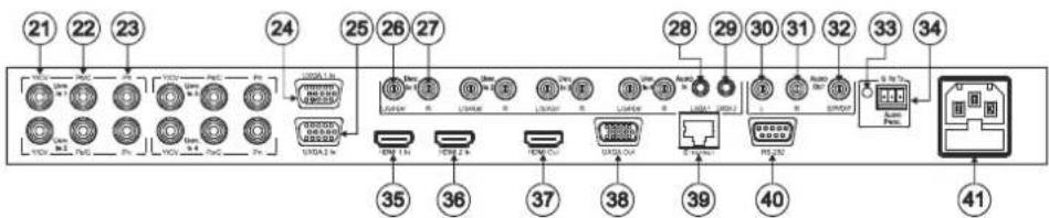
Figure 2: VP-729 Presentation Switcher/Scaler Rear Panel
| # | Feature | Function | ||
| 21 | UNIV. IN RCA Connectors (from 1 to 4) | Y/CV | Connects to the video acceptor which can be either composite video (Y/CV), s-Video (Y/CV, Pb/C ) or component video (Y/CV, Pb/C, Pr) | |
| 22 Pb/C | ||||
| 23 Pr | ||||
| 24 | UXGA 1 IN 15-pin HD Connector | Connects to the UXGA (analog interface) graphics source 1 | ||
| 25 | UXGA 2 IN 15-pin HD Connector | Connects to the UXGA (analog interface) graphics source 2 | ||
| 26 | AUDIO IN UNIV. IN RCA Connectors (from 1 to 4) | L/S/PDIF | Connects to the left unbalanced stereo analog audio source.Alternatively, connect to a digital audio source | |
| 27 | R | Connects to the right unbalanced stereo analog audio source | ||
| 28 | AUDIO IN 3.5 Mini Jack | UXGA 1 | Connects to the unbalanced stereo analog audio source 1 | |
| 29 | UXGA 2 | Connects to the unbalanced stereo analog audio source 2 | ||
| 30 | AUDIO OUT RCA Connectors | L | Connects to the left channel of the unbalanced stereo analog audio acceptor | |
| 31 | R | Connects to the right channel of the unbalanced stereo analog audio acceptor | ||
| 32 | S/PDIF | Connects to a digital audio acceptor | ||
| 33 | AUDIO PROG | Program Button | Push to upgrade to the latest Kramer audio firmware.Release for normal operation | |
| 34 | Terminal Block Connector | Connects to a PC for audio firmware upgrade | ||
| 35 | HDMI 1 IN Connector | Connects to the HDMI 1 source | ||
| 36 | HDMI 2 IN Connector | Connects to the HDMI 2 source | ||
| 37 | HDMI OUT Connector | Connects to the HDMI acceptor | ||
| 38 | UXGA OUT 15-pin HD Connector | Connects to the video acceptor that displays the scaled output.In the default HDTV mode, the signal is transmitted via 3 pins: PIN 1 is Pr, PIN 2 is Y, PIN 3 Pb | ||
| 39 | ETHERNET Port | Connects to your LANLocal Area Network – that is computers sharing a common communications line or wireless link,which often share a server within a defined geographic area | ||
| 40 | RS-232 9-pin D-sub Connector | Connects to a PC or serial controller | ||
| 41 | Power Connector with Fuse | AC connector for connecting power to the unit | ||
4 Installing in a Rack
This section provides instructions for rack mounting the unit.
Before installing in a rack, be sure that the environment is within the recommended range:
| OPERATING TEMPERATURE: | 0° to +55°C (32° to 131°F) |
| STORAGE TEMPERATURE: | -45° to +72°C (-49° to 162°F) |
| HUMIDITY: | 10% to 90%, RHL non-condensing |

CAUTION!
When installing on a 19" rack, avoid hazards by taking care that:
- It is located within the recommended environmental conditions, as the operating ambient temperature of a closed or multi unit rack assembly may exceed the room ambient temperature.
- Once rack mounted, enough air will still flow around the machine.
- The machine is placed straight in the correct horizontal position.
- You do not overload the circuit(s). When connecting the machine to the supply circuit, overloading the circuits might have a detrimental effect on overcurrent protection and supply wiring. Refer to the appropriate nameplate ratings for information. For example, for fuse replacement, see the value printed on the product label.
- The machine is earthed (grounded) in a reliable way and is connected only to an electricity socket with grounding. Pay particular attention to situations where electricity is supplied indirectly (when the power cord is not plugged directly into the socket in the wall), for example, when using an extension cable or a power strip, and that you use only the power cord that is supplied with the machine.
To rack-mount a machine:
- Attach both ear brackets to the machine. To do so, remove the screws from each side of the machine (3 on each side), and replace those screws through the ear brackets.

natural_image
Technical line drawing of a mechanical bracket assembly with bolts and rods (no text or symbols)- Place the ears of the machine against the rack rails, and insert the proper screws (not provided) through each of the four holes in the rack ears.
Note:
• In some models, the front panel may feature built-in rack ears
- Detachable rack ears can be removed for desktop use
• Always mount the machine in the rack before you attach any cables or connect the machine to the power
- If you are using a Kramer rack adapter kit (for a machine that is not 19"), see the Rack Adapters user manual for installation instructions available from our Web site
5 Connecting the VP-729

Always switch off the power to each device before connecting it to your VP-729. After connecting your VP-729, connect its power and then switch on the power to each device.
To connect the VP-729 as illustrated in the example in Figure 3, do the following:
1. Connect the video sources:
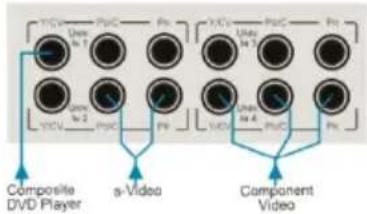
A component video source (for example, a DVD player) to the UNIV. IN 1 RCA connectors, Y/CV, Pb/C and PR
Component video is sometimes called YUV, or Y, B-Y, R-Y
An s-Video source (for example, a DVD player) to the UNIV. IN 4 RCA connectors, Y/CV and PB/C
A computer graphics source to the UXGA 1 IN 15-pin HD computer graphics video connector
An HDMI source (for example, a DVD player) to the HDMI 1 IN connector
A graphics data source (for example, JPEG files, that should be smaller than 1MB and should not exceed a resolution of 2048x1536, from a PC or a USB flash drive) to the USB connector on the front panel of the machine
2. Connect the unbalanced stereo or digital audio sources:
The audio of the component video source 1 to the AUDIO UNIV IN 1 S/PDIF RCA connector
The audio of the s-Video source 4 to the AUDIO UNIV IN 4 L and R RCA connector
The audio of computer graphics source to the AUDIO UXGA 1 3.5mm mini jack
Although this connecting example shows only several inputs that are connected, you can connect all the inputs simultaneously
3. Connect the video outputs:
The HDMI OUT connector to an HDMI acceptor (for example, a plasma display)
The UXGA OUT 15-pin HD computer graphics video connector to a video acceptor (for example, an analog display)
In the HDTV mode, the signal goes out via three PINS: PIN 1 is Red or Pr, PIN 2 is Green or Y, PIN 3 is Blue or Pb
-
Connect the AUDIO OUT L and R unbalanced stereo audio output and/or the S/PDIF digital audio output to audio acceptors, for example, power amplifiers.
-
Connect the power cord.
We recommend that you use only the power cord that is supplied with this machine
- If required, connect:
A PC via RS-232, (see Page 11)
The ETHERNET port, see Section 5.2

The USB connector, audio sources and acceptors, and power cord are not shown in Figure 3.

flowchart
graph TD
    A["Server"] -->|YUV| B["DVD Player (Component)"]
    A -->|Y/C| C["DVD Player (s-Video)"]
    A -->|VGA| D["Computer Graphics Source"]
    A -->|Control via Ethernet| E["DVD Player (HDMI)"]
    A -->|HDMI| F["Plasma Display"]
    A -->|VGA| G["Analog Display"]
    A -->|RS-232| H["RS-232"]
    style A fill:#f9f,stroke:#333
    note right of A: Audio connections are not shown
Figure 3: Connecting to the VP-729 Rear Panel
5.1 Connecting a PC
You can connect to the unit via a crossed RS-232 connection, using for example, a PC. A crossed cable or null-modem is required as shown in method A and B respectively. If a shielded cable is used, connect the shield to pin 5.
Method A (Figure 4)—Connect the RS-232 9-pin D-sub port on the unit via a crossed cable (only pin 2 to pin 3, pin 3 to pin 2, and pin 5 to pin 5 need be connected) to the RS-232 9-pin D-sub port on the PC.
Note: There is no need to connect any other pins.

Figure 4: Crossed Cable RS-232 Connection
Hardware flow control is not required for this unit. In the rare case where a controller requires hardware flow control, short pin 1 to 7 and 8, and pin 4 to 6 on the controller side.
Method B (Figure 5)—Connect the RS-232 9-pin D-sub port on the unit via a straight (flat) cable to the null-modem adapter, and connect the null-modem adapter to the RS-232 9-pin D-sub port on the PC. The straight cable usually contains all nine wires for a full connection of the D-sub connector. Because the null-modem adapter (which already includes the flow control jumpering described in Method A above) only requires pins 2, 3 and 5 to be connected, you are free to decide whether to connect only these 3 pins or all 9 pins.
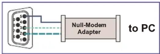
Figure 5: Straight Cable RS-232 Connection with a Null Modem Adapter
5.2 Connecting the VP-729 via the ETHERNET Port
To connect and configure the Ethernet port of the VP-729, refer to the ETHERNET Configuration (Lantronix) GUIDE on our Web site: http://www.kramerelectronics.com.
6 Presentation Switcher / Scaler Buttons
The VP-729 includes the following front panel buttons:
• Nine INPUT selector buttons
- A PIP button
- BLANK and FREEZE buttons
- Six OSD buttons
• A RESET TO XGA/720p button
• A PANEL LOCK button
6.1 Switching an Input
Each INPUT SELECTOR button can be used to select the source. When selected, the button illuminates.
You can switch seamlessly between each input that is connected to a source by pressing the appropriate INPUT SELECTOR button.
SEAMLESS SWITCHING - FTB™ switching for glitchless transitions between inputs
6.2 The PIP Button Feature
The Picture-in-Picture inserter (PIP) uses K-IIT XL ^™ image insertion technology to present video and graphic sources simultaneously so that you can display:
• An inserted video source PIP over a graphic source background
- An inserted graphic source PIP over a video source background
VIDEO SOURCE – can be composite or s-Video
GRAPHIC SOURCE – can be HDMI, UXGA or component
For example, you can show a live video window on top of a graphic background and vice versa.
If the HDMI signal is HDCP protected, it cannot appear on a display that is not HDCP compliant and the machine will not output a picture on the VGA output
The VP-729 supports three PIP modes:
- Picture-in-Picture, with a smaller window superimposed over a full screen image
- Picture + Picture, where both images are placed side-by-side with the same height
- Split, where both images appear side-by-side and the aspect ratios of both images are maintained
6.2.1 Activating the PIP Feature
Activate the PIP feature in any of the following ways:
- Press and hold the PIP front panel button while pressing the input button of the required PIP source
- Press the PIP key on the IR remote control transmitter (see Section 6.4)
- Access the OSD PIP menu (see Figure 13) and selecting PIP On
6.2.2 Selecting the PIP Source
To easily select the PIP source, press and hold the PIP front panel button while pressing the input button of the required PIP source.
For example, to select UXGA 2 as the graphic PIP source over a video background, press the PIP front panel button while pressing the UXGA 2 front panel button.
To select the PIP source using the IR remote controller, press the desired PIP source on the remote controller.
For example, if you want to select HDMI 2 as the PIP source, press the HDMI 2 button in the PIP source area on the IR remote controller.
To set the PIP source via the OSD menu, do the following:
-
Press the MENU button to enter the OSD menu.
-
Press the button to move to the PIP icon.
-
Scroll down to select Source and press ENTER.
-
Use the ▲ or ▼ buttons to select the PIP Source from the drop-down list box, and press ENTER (see Figure 13).
-
To exit the OSD menu, press the MENU button.

natural_image
Black-and-white photo of a ram standing in grass next to a traditional barn with a sloped roof (no visible text or symbols)Figure 6: PIP Source over Background
To replace a PIP source in the same category (for example, changing the PIP source from HDMI 2 to HDMI 1), press the required PIP Source on the remote control transmitter and the PIP display will change accordingly.

When attempting to select a PIP source of the same category as the background source (for example, video on video, which is not compliant with the table on Page 16), a message is displayed, "Unavailable Operation".
6.2.3 Toggling between the PIP and the Screen Source (Swap)
To toggle back and forth between the PIP source and the main display, as Figure 7 illustrates, press the Swap key on the infrared remote control transmitter (see Figure 8). You can also do this via the OSD menu by selecting a new Input Source through the Input menu and a new PIP source through the PIP menu.

natural_image
Black-and-white photo of a ram lying on grass beside a calm river, with an inset showing a landscape (no text or symbols)
natural_image
Black-and-white photo of a sheep resting on a pond with trees and sky in the background (no text or symbols visible)Figure 7: The SWAP Status
When selecting one PIP source, the VP-729 automatically recognizes and displays the selected graphic PIP source on all the video displays and the selected video source on all the graphic displays, compliant with the table on Page 16.
The PIP source appears even if the input signal is not connected. In this case the PIP appears over a blank screen
To replace a PIP in the same input signal category (for example, changing from UXGA 1 to HDMI 2), press the button for that PIP Source on the remote control transmitter and the PIP display will change accordingly.
| PIP Source Appearance Availability | ||||||||||||||||||
| Main Source | PIP Source | |||||||||||||||||
| Input 1 | Input 2 | Input 3 | Input 4 | VGA 1 | VGA 2 | HDMI 1 | HDMI 2 | USB | ||||||||||
| Video | YC | Comp | Video | YC | Comp | Video | YC | Comp | Video | YC | Comp | |||||||
| Input 1 | Video | x | x | x | x | x | √ | x | x | √ | x | x | √ | √ | √ | √ | √ | x |
| YC | x | x | x | x | x | √ | x | x | √ | x | x | √ | √ | √ | √ | √ | x | |
| Comp | x | x | x | √ | √ | x | √ | √ | x | √ | √ | x | x | x | x | x | x | |
| Input 2 | Video | x | x | √ | x | x | x | x | x | √ | x | x | √ | √ | √ | √ | √ | x |
| YC | x | x | √ | x | x | x | x | x | √ | x | x | √ | √ | √ | √ | √ | x | |
| Comp | √ | √ | x | x | x | x | √ | √ | x | √ | √ | x | x | x | x | x | x | |
| Input 3 | Video | x | x | √ | x | x | √ | x | x | x | x | x | √ | √ | √ | √ | √ | x |
| YC | x | x | √ | x | x | √ | x | x | x | x | x | √ | √ | √ | √ | √ | x | |
| Comp | √ | √ | x | √ | √ | x | x | x | x | √ | √ | x | x | x | x | x | x | |
| Input 4 | Video | x | x | √ | x | x | √ | x | x | √ | x | x | x | √ | √ | √ | x | |
| YC | x | x | √ | x | x | √ | x | x | √ | x | x | x | √ | √ | √ | x | ||
| Comp | √ | √ | x | √ | √ | x | √ | √ | x | x | x | x | x | x | x | x | x | |
| VGA 1 | √ | √ | x | √ | √ | x | √ | √ | x | √ | √ | x | x | x | x | x | x | |
| VGA 2 | √ | √ | x | √ | √ | x | √ | √ | x | √ | √ | x | x | x | x | x | x | |
| HDMI 1 | √ | √ | x | √ | √ | x | √ | √ | x | √ | √ | x | x | x | x | x | x | |
| HDMI 2 | √ | √ | x | √ | √ | x | √ | √ | x | √ | √ | x | x | x | x | x | x | |
| USB* | √ | √ | x | √ | √ | x | √ | √ | x | √ | √ | x | x | x | x | x | x | |
| ✓ means Yes; x means No*For a USB source with the PIP enabled, the output image size is limited to 960 horizontal pixels | ||||||||||||||||||
6.3 Locking and Unlocking the Front Panel
To prevent changing the settings accidentally or tampering with the unit via the front panel buttons, lock your VP-729.
Unlocking releases the protection mechanism.
When the front panel is locked, control is still available via RS-232 and/or the Ethernet.
To lock the VP-729:
- Press the PANEL LOCK button on the front panel.
The front panel is locked and the PANEL LOCK button is illuminated.
Pressing any button other than the PANEL LOCK button has no effect
To unlock the VP-729:
- Press the illuminated PANEL LOCK button on the front panel The front panel unlocks and the PANEL LOCK button is no longer illuminated
The Save Lock and Input Lock OSD functions are defined in the table on Page 32.
6.4 The Infrared Remote Control Transmitter
You can control the VP-729 remotely from the infrared remote control transmitter which is powered by two AAA size 1.5V DC batteries. The IR remote control transmitter:
• Has a range of up to 15 meters
• Delivers instantaneous results
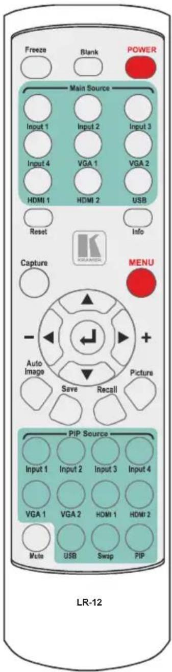
Figure 8: IR Remote Control Transmitter
| Key | Function |
| Freeze | Pauses the output video and can be programmed to mute the audio signal at the same time (see Page 32) |
| Blank Toggles | between a blank screen (blue or black) and the display |
| POWER Cycles power | |
| Main Source | 9 keys for selecting one of the following sources: Input 1, Input 2, Input 3, Input 4, VGA 1, VGA2, HDMI 1, HDMI 2, and USB |
| Reset Press | and hold to reset to the default resolution (toggles between RESET TO XGA and 720p) |
| Info | Press to toggle the Info OSD menu |
| Capture | Captures an image to place as a logo or background (see Page 31) |
| MENU | Shows the main OSD Menu |
| Navigation arrows | Allows maneuvering within an OSD screen (left, right, up and down, as well as the ENTER arrow at the center). The + and - buttons increase and decrease the volume level, respectively (when not in the OSD menu) |
| Auto Image | Press to assess the image and improve the quality accordingly, by automatically adjusting the phase, frequency and position |
| Save | Press to save a profile |
| Recall | Press to recall a profile |
| Picture | Press to display the Picture OSD menu |
| PIP source | 9 keys for selecting one of the following PIP sources: Input 1, Input 2, Input 3, Input 4, VGA 1, VGA2, HDMI 1 and HDMI 2 |
| Mute | Press to mute the audio signal |
| Swap Press | to toggle between the PIP content and the parent screen content |
| PIP | Press to select the picture-in-picture (the PIP button illuminates) see Page 13 |
7 Configuring the VP-729 via the OSD MENU Screens
The VP-729 uses an on-screen display (OSD) menu for system configuration. The menu appears as an overlay over any images that are output from the VP-729.
There are eight sub-menus that are used to configure the VP-729. You can activate and navigate these menus from the front panel buttons, or from the IR remote control.

Figure 9: MENU Items
To access and use the OSD menus, push the button for the desired input signal, then press the MENU front panel OSD button or the MENU key on the infrared remote control transmitter to display the main MENU screen which shows the eight interactive icons.
- Press the ◀ or ▶ buttons to select the desired sub-menu, and then press ENTER
- Press the ▲ or ▼ buttons to select the menu item to be adjusted, and then press ENTER
- Press the ▲ or ▼ buttons to make the adjustment and then press ENTER, or
- Press the ◀ or ▶ buttons to increase or decrease the (numerical) value as needed
To return to the previous menu level, press the front panel MENU button or the MENU key on the remote control. All settings and adjustments are automatically saved in non-volatile memory for each of the inputs (except USB).

The values defined in the different menus may change according to the firmware version (you can download the up-to-date firmware version from our Web site at http://www.kramerelectronics.com).
7.1 The Input Screen

Figure 10: Input Screen
| Setting | Function | Default |
| Source | Select the source: Input 1, Input 2, Input 3, Input 4, VGA 1, VGA 2, HDMI 1, HDMI 2 or USBWhen switching sources, the image fades through blackThe source is automatically updated when pressing an input front panel button on the machine | |
| Input (1 to 4) Source Type | Select the source type: Component, YC or video (CV) | Video |
| Image Name Select the file | name of the image displayed when the USB port is selected as an inputThis feature is available when the slideshow feature is set to Off (see Section 7.7.1)This feature supports JPEG format only. The JPEG file should be smaller than 1MB and should not exceed a resolution of 2048x1536.If the image file is not within the definition, the machine displays the message: “Size Too Big” | |
| Color Format | Select the color format: Auto, RGB or YUV | Auto |
| Video Standard Select the video | video standard: Auto, NTSC, PAL,PAL-M, PAL-N, NTSC 4.43, SECAM or PAL-60 | Auto |
| H-Position | Set the horizontal position according to the input resolutionFor UXGA and component video inputs | |
| V-Position Set the vertical position | position according to the input resolution | |
| Frequency | Adjust the frequency: 0 to 50For UXGA inputs | 0 |
| Phase Adjust the phase: 0 to 31 0 | ||
| Auto image Assesses the image and improves the quality accordingly, by automatically adjusting the phase,frequency and position | ||
7.1.1 Reading JPEG Files
You can read the JPEG files via the USB input. The JPEG files can be used to display a JPEG image, download a new Logo or background (see Page 31) or create a slideshow (see Section 7.7.1).
To read JPEG files:
- Load the JPEG images (the JPEG file should be smaller than 1MB and should not exceed a resolution of 2048x1536) to the route directory of a USB memory stick.
- Connect the Memory stick to the USB connector on the front panel.
- Select the USB INPUT button on the front panel.
- Select the desired image.
7.2 The Picture Screen
The Brightness, Contrast, Color and Hue picture settings are saved individually for each input (except USB).
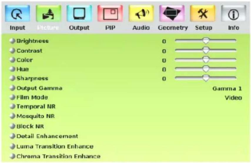
Figure 11: Picture Screen
| Setting | Function | Default |
| Brightness | Adjust the brightness: 0 to 100 | 50 |
| Contrast | Adjust the contrast: 0 to 100 | 50 |
| Color | Adjust the color: 0 to 100 | 55 |
| Hue | Adjust the hue: 0 to 360 | 180 |
| Sharpness | Adjust the sharpness: 0 to 100 | 50 |
| Output Gamma | Adjust the gamma: Gamma 1 to Gamma 5 | Gamma 1 |
| Film Mode | Set the film mode: Auto, Video, Film | Auto |
| Temporal NR | Set the temporal noise reduction level: Off, Low, Medium, High | High |
| Mosquito NR | Set the Mosquito noise reduction level: Off, Low, Medium, High | Low |
| Block NR | Set the block noise reduction level: Off, On | Off |
| Detail Enhancement | Set the detail enhancement: Off, Low, Medium, HighIf the USB input is selected, Detail Enhancement is set to Off | Medium |
| Luma Transition Enhance | Set the luminance transition enhance level: Off, Low, High | Low |
| Chroma Transition Enhance | Set the chrominance transition enhance level: Off, Low, High | Low |
7.3 The Output Screen

Figure 12: Output Screen
| Setting | Function | Default |
| Resolution | Set the resolution: Native HDMI, 640x480x60Hz, 640x480x75Hz, 800x600x50Hz, 800x600x60Hz, 800x600x75Hz, 1024x768x50Hz, 1024x768x60Hz, 1024x768x75Hz, 1280x768x50Hz, 1280x768x60Hz, 1280x720x60Hz, 1280x800x60Hz, 1280x1024x50Hz, 1280x1024x60Hz, 1280x1024x75Hz, 1366x768x50Hz, 1366x768x60Hz, 1400x1050x50Hz, 1400x1050x60Hz, 1600x1200x50Hz, 1600x1200x60Hz, 1680x1050x60Hz, 1920x1080x60Hz, 1920x1200x60Hz, 480px60Hz, 576px60Hz, 720px50Hz, 720px60Hz, 1080ix50Hz, 1080ix60Hz, 1080px50Hz, 1080px60Hz, 720x480x59.94Hz, 1280x720x59.94Hz, 1920x1080ix59.94Hz, 1920x1080x23.98Hz, 1920x1080x29.97Hz, 1920x1080x59.94Hz or Custom (from 1 to 4)Note that any change in the resolution must be confirmed via the count-down message that appears on the screenThe embedded audio feature is not available for the 1920x1200The embedded audio feature is not available for theRGBresolutions 1920x1200 and 1920x1080. (It is available for 1080p) | 1024x768@60Hz |
| HDMI Type | Set the HDMI type: Auto, HDMI, DVI | Auto |
| Aspect Ratio | Set the aspect ratio (also seeSection 7.3.1):Best Fit- the best possible compromise between the input and the output aspect ratiosLetterboxFollow Output- If the input ≤ output, scale up the picture.If the input ≥ output, scale down the pictureVirtual WideFollow Input- If the input ≤ output, display with a blank border. If the input ≥ output, crop the imageCustom | Follow Output |
| H-Pan | Horizontal pan: -16 to 16This feature is available when selecting Custom aspect ratio | 0 |
| V-Pan | Vertical pan: -16 to 16This feature is available when selecting Custom aspect ratio | 0 |
| H-Zoom | Horizontal zoom: -8 to 8This feature is available when selecting Custom aspect ratio | 0 |
| V-Zoom | Vertical zoom: -8 to 8This feature is available when selecting Custom aspect ratio | 0 |
| Zoom | Set the Zoom: 100%, 150%, 200%, 225%, 250%, 275%, 300%, 325%, 350%, 375%, 400% or Custom | 100% |
| Custom Zoom | Set the Zoom: From 100% to 400% | |
| Zoom H-Pan | 0 to 31 | 16 |
| Zoom V-Pan | 0 to 31 | 16 |
7.3.1 Selecting the Correct Aspect Ratio
You can configure the aspect ratio of any output image to fit your application. The VP-729 offers six different aspect ratio settings: Best Fit, Letterbox, Follow Output, Virtual Wide, Follow Input, and Custom. Here is how each of these settings works.
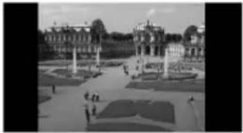
BEST FIT – This setting re-sizes the video or graphics input signal to "best fit" the output resolution while maintaining the aspect ratio of the input signal. For example, a composite video signal (4:3 aspect ratio) will "best fit" to the top and bottom of a widescreen output image, resulting in black pillars on either side.
LETTERBOX – This setting compresses the top and bottom edges of the input signal, but fills the width of the screen.
natural_image
Exterior view of a grand palace with symmetrical gardens and central towers (no signage or text visible)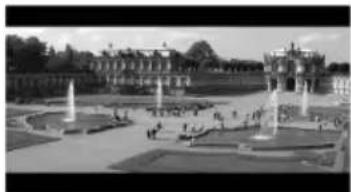
natural_image
Exterior view of a grand palace with fountains and manicured gardens (no signage or text visible)FOLLOW OUTPUT – The aspect ratio and resolution of the input signal is re-sized to precisely match the aspect ratio and resolution of the VP-729 output signal. This may result in some distortion to the input signal images

natural_image
Exterior view of a grand palace with fountains and manicured gardens (no signage or text visible)VIRTUAL WIDE – The input signal is stretched horizontally to fit the width of a widescreen output image from the VP-729. This setting is used to expand anamorphic (horizontally compressed) video images from DVDs

natural_image
Two black-and-white photos showing a fountain in an open plaza with buildings and trees in the background (no visible text or symbols)FOLLOW INPUT – The aspect ratio and resolution of the input video or graphics signal are both preserved. For example, a composite video image with a 4:3 aspect ratio will appear with the same aspect ratio on a 1080p (16:9) output image, surrounded by black bars

natural_image
Exterior view of a grand courtyard with symmetrical buildings and central plaza (no visible text or signage)CUSTOM – Use this menu to define a custom aspect ratio by adjusting the output image horizontal size (width) and vertical size (height)

natural_image
Black-and-white exterior view of a grand palace with fountains and manicured gardens (no visible text or signage)7.4 The PIP Screen

Figure 13: PIP Screen
| Setting | Function | Default |
| On/Off | Activate/deactivate the PIP feature: On/OffFor a USB source with the PIP enabled, the maximum output image size is 960 horizontal pixels | Off |
| Type | Select the PIP type: Picture-In-Picture, Picture + Picture or Split (see Section 6.2) | Picture-In-Picture |
| Source | Select the PIP source (see table in Page 16)When changing the PIP source, the display fades through black | |
| PIP Size | Select the PIP size: 1/25, 1/16, 1/9, 1/4, or CustomThe PIP size can be set up to the full height and up to half the width of the screen | 1/4 |
| H-Position | Set the horizontal position of the PIP on the display: 0 – 128 | 3 |
| V-Position | Set the vertical position of the PIP on the display: 0 – 128 | 0 |
| H-Size | Set custom size: 1 – 256The actual range depends upon the input resolution | |
| V-Size | Set custom size: 1 – 256The actual range depends upon the input resolution | |
| Frame | Turn the PIP frame on or off: On/Off | On |
| Frame Color | Select the color of the PIP frame: Red, Green or Blue | Blue |
7.5 The Audio Screen

Figure 14: Audio Screen
| Setting | Function | Default |
| Type | Select the audio input type (available for IN 1 to IN 2): Analog or S/PDIF | Analog |
| Input Volume | Adjust the input volume: -22 to 22 | 0 |
| Output Volume | Adjust the output volume: -100 to 24 | 0 |
| Bass | Adjust the bass: -36 to 36 | 0 |
| Treble | Adjust the treble: -36 to 36 | 0 |
| Balance | Adjust the balance: -10 to 10 | 0 |
| Loudness | Set the loudness: On/Off | Off |
| Delay | Define the delay type: Dynamic or User DefineSelect Dynamic for the audio delay to equal the pipeline video delay or User Define to set the delay time manually (via User Delay) | Dynamic |
| User Delay | Available when selecting the User Defined delay: 0 to 340 (msec)Set the delay in 2msec steps | 0 |
| USB | Select the audio signal to follow the USB signal: No Audio, Input 1, Input 2, Input 3, Input 4, VGA 1, VGA 2, HDMI 1 or HDMI 2 | No Audio |
7.6 The Geometry Screen

Figure 15: Geometry Screen
| Setting | Function | Default |
| Application | Select the output application: Keystone, Anyplace or Rotation | Keystone |
| Location | Select the location of the display: Front, Rear, Ceiling or Rear ceiling | Front |
| Horizontal Keystone | Adjust the horizontal keystone: -40 to 40If the projector is located at an angle to the left or right of the screen | 0 |
| Vertical Keystone | Adjust the vertical keystone: -30 to 30If the projector is located at an angle above or below the screen | 0 |
| Diagonal Projection Move the location of each corner of the display separately: Top Left, Top Right, Bottom Left,Bottom Right or Reset (to reset diagonal projections settings) | Top Left | |
| Pincushion/Barrel | Adjust the pincushion or barrel appearance of the screen: -20 to 20 | 0 |
| Rotation Rotate the display by 180 degrees clockwise or counterclockwise: -180 to 180 | 0 | |
| Reset all | Resets the geometry values to their default value | |
The settings available for each application are defined in the following table:
| Application | Available Settings |
| Keystone Location, horizontal keystone, vertical keystone,pincushion/barrel and Reset all | |
| Anyplace | Location, Diagonal Projection and Reset all |
| Rotation | Location, pincushion/barrel, Rotation and Reset all |
7.7 The Setup Screen

Figure 16: Setup Screen
| Setting | Function | Default |
| Save | Saves up to eight profiles from 1 to 8 | |
| Recall | Recalls a profile from 1 to 8 | |
| Slideshow | Set the speed for the slide show to Min, Low, Mid, Long, Max or Off (see Section 7.7.1) | Min |
| Frame Lock Locks the vertical refresh rate of the output to that of the input. Set to On or Off. Note that seamless switching is not possible when working in the Frame Lock mode unless all sources are frame synchronized. In cases where the output resolution can support the vertical refresh rate of the input, the output refresh rate will change according to the input refresh rate | Off | |
| Auto Image | Automatically adjusts and aligns the picture each time one of the UXGA inputs is selected or if the UXGA input resolution has changed. Set to Manual or Auto | Manual |
| Switching Mode | Selects seamless switching (fade-through-Black) or Fast switching which is faster but may cause glitches on the output (applies when switching between analog inputs) | Seamless |
| Factory Reset | Select Yes to reset your VP-729 to its preset default settings | |
| Advanced Setup | Opens the advanced setup menu screen (see Figure 17), which includes the: Mode Set, OSD, Misc, Input and Output OSD menus (Section 7.8) | |
| HDMI Switch Behavior | Set to DVD/Normal or PC/Bypass Set to Normal for sources with HDCP. When in Normal operation, the unit sends a hot plug to the source for any Group/Scaler switching request. There might be some graphic cards that might shut OFF the VGA/HDMI output following the hot plug detection. To prevent this, set this parameter to the Bypass mode so the unit will not send a hot plug for switching request (the hot plug will be detected by the source only when plugging a physical connection) | Normal |
| HDMI Input HDCP | Set to On or Off for each HDMI inputHDCP support can be enabled (On) or disabled (Off) for each of the HDMI inputs, allowing the source to transmit a non-HDCP signal if required (for example, when working with a Mac computer) |
7.7.1 The Slideshow Feature
The VP-729 lets you run a slideshow via the USB input and set the slideshow speed via the slideshow feature.
To prepare a slideshow:
- Load the slideshow JPEG images to a USB memory stick.
The slides will appear in alphabetical order.
The JPEG file should be smaller than 1MB and should not exceed a resolution of 2048x1536 - Open the Setup menu and set the desired speed in the slideshow item and then close the menu.
- Connect the Memory stick to the USB connector on the front panel.
- Select the USB INPUT button on the front panel.
The slideshow begins at the set speed.
You have to set the slideshow parameters before you run the slideshow
You can control the slide show by pressing the:
- FREEZE button to pause
• USB button to play and stop the slideshow
• ▲ (up arrow) button to go to the previous slide
• ▼ (down arrow) button to go to the next slide
7.8 The Advanced Setup Screen

Figure 17: Advanced Setup Screen
The Mode Set functions define the desired working resolution and refresh rate when the system cannot distinguish between similar resolutions (for example, resolutions that have the same number of lines can be defined to identify refresh rate values.
| Setting | Function | Selection/Range | Default |
| Mode 1 | Set mode 1 | 1400x1050x60Hz1680x1050x60Hz | 1400x1050x60Hz |
| Mode 2 | Set mode 2 | 1280x1024x75Hz1280x1024x76Hz | 1280x1024x75Hz |
| Mode 3 | Set mode 3 | 1280x768x60Hz1366x768x60Hz | 1280x768x60Hz |
If two resolutions have the same number of lines (for example, 1050), we can define them so that the unit identifies them as 1400x1050 or as 1680x1050.
7.8.1 The OSD Screen Functions
| Setting | Function | Selection/Range | Default |
| Menu Position | Set the location of the OSD menu | Center, Top Left, Top Right, Bottom Left, Bottom Right | Center |
| Time Out (sec) | Set the OSD menu timeout | 5, 10, 20, 30, 60, 90 or Off | 30 |
7.8.2 The Misc Screen functions

Figure 18: Misc Screen
| Setting | Function | Default |
| Logo Select On, Off or CustomChoose ON for the start up logo to appear on the screen Choose OFF for it not to appearSet to Custom to download a custom Logo (Flash ROM).The logo can be obtained via the Capture function or downloaded via USB (Logo Download) | Kramer Logo | |
| Blank Color Select Black or BlueSet the blank color (the color that appears on the screen when the blank button is pressed) | Blue | |
| Capture | Press to capture the currently displayed image.The machine prompts “Capture”.This captured image can be used as a logo or as the background if the background setting is set to Custom, or when no input is connected and the output sync is ON. 1. The unit can capture the image for an input source with a resolution up to 1920x1200If the output resolution is too high, the machine prompts "Output resolution too high for Capture"2. The output resolution must be <1400 horizontal pixels in order to capture3. The PIP must be off in order to use the capture featureThe machine prompts “Cannot Capture with PIP” If PIP is on 1. The unit can capture the image for an input source with a resolution up to 1920x1200If the output resolution is too high, the machine prompts "Output resolution too high for Capture"2. The output resolution must be <1400 horizontal pixels in order to capture3. The PIP must be off in order to use the capture featureThe machine prompts “Cannot Capture with PIP” If PIP is on | |
| Background | Select Blue, Black, Custom or Disable Analog Sync to set the background screen color if an input without a signal is selectedSelecting Custom will automatically bring up a custom (captured) screen image, that can be obtained via the Capture function or downloaded via USB (Logo Download)Selecting Disable Analog Sync will cause the output SYNC to turn to off if an output is not connected for over 2 minutes for better energy efficiency | Default |
| Save Lock Select | On or OffSet to ON to save the lock status when the machine is powered down | Off |
| Input Lock Select | On or OffSet to OFF so you can still use the SOURCE buttons on the front panel even when the lock button is on | On |
| Firmware Download | Select and confirm to download the firmware via the USB connection | |
| Logo Download | Download a new logo via the USB connectionMake sure the USB is not selected as the system input when downloading the logo | |
| Blank Select Blank | & Mute, Blank or Mute to determine the behavior of the BLANK front panel buttonSet to Blank & Mute to blank the output image and mute the audioSet to Blank to blank the outputSet to Mute to mute the audio | Blank & Mute |
| Freeze | Select Freeze & Mute, Freeze or Mute to determine the behavior of the FREEZE front panel buttonSet to Freeze & Mute to Freeze the output image and mute the audioSet to Freeze to Freeze the outputSet to Mute to mute the audio | Freeze & Mute |
| HDCP Setting | Select Follow Input or Follow Output to define whether the HDCP will follow the input or the outputWhen Follow Input is selected, the scaler changes its HDCP output setting (for the HDMI output) according to the HDCP of the input.This option is recommended when the HDMI scaler output is connected to a splitter/switcher (in this mode, switching may not be glitch-free)When Follow Output is selected, the scaler matches its HDCP output to the HDCP setting of the HDMI acceptor to which it is connected.This ensures smooth switching, regardless of the input | Follow Output |
| Overscan Select | On or OffSet to On to Allow stretching of the outputted pictureThis feature is enabled only for HD input resolutions | Off |
7.8.3 The Input Functions Screen

Figure 19: Input Functions
| Setting | Function | Default |
| Custom Input | Custom Input from Custom 1 to custom 4 | Custom 1 |
| HT Horizontal Total | 1344 | |
| HW Horizontal sync pulse width | 136 | |
| HS Horizontal active start point | 296 | |
| HA | Horizontal active region | 1024 |
| HP Horizontal polarity | ||
| VT Vertical Total 806 | ||
| VW | Vertical sync pulse width | 6 |
| VS | Vertical active start point | 35 |
| VA Vertical active region 768 | ||
| VP Vertical polarity | ||
| OCLK | Output clock | 65 |
| Enable | Set to On to enable parameter change | Off |
| Save | Apply settings | N/A |
7.8.4 The Output Functions Screen

Figure 20: Output Functions
| Setting | Function | Default |
| Custom Output | Custom 1 to Custom 4 | |
| HT Horizontal total 1344 | ||
| HW | Horizontal sync pulse width | 136 |
| HS | Horizontal active start point | 296 |
| HA | Horizontal active region | 1024 |
| HP Horizontal polarity | ||
| VT | Vertical total | 806 |
| VW | Vertical sync pulse width | 6 |
| VS | Vertical active start point | 35 |
| VA | Vertical active region | 768 |
| VP | Vertical polarity | |
| OCLK | Output clock | 65 |
| Apply | Press to apply the settings | |
| Save | Save setup | |
| Set Current | Import the values of the currently selected output resolution into the User Mode Setting | N/A |
| Read EDID | Reads the EDID file from the acceptor that is connected to the HDMI output. The EDID is stored as a custom output resolution.This allows automatic handling of LED screens that support very low non-standard resolutions | |
Figure 21 illustrates horizontal and vertical sync pulse width, timing and active video area for a typical frame of video.
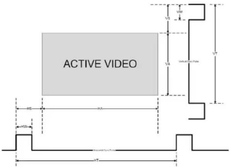
Figure 21: Active Video Functions
7.9 The Info Screen
From the Information screen (see Figure 22), you can verify the main source, PIP source, the output resolution, the SYNC mode, as well as the firmware revision and the audio board firmware version (for example, 2.9 in Figure 22):

Figure 22: Information Screen

When the output resolution is 1920x1080 or 1920x1200, "No Embedded Audio" will appear in brackets next to the resolution.
8 Using Text Overlay
The text overlay feature is accessed via the Application Program (AP).
Running this AP with the PC connected to the VP-729 lets you display text over the screen, with features including text color and speed, transparency, text position and repetition. Current text overlay settings can be saved and loaded to the AP.

Figure 23: Text Overlay Application Screen
| Feature | Function | |
| Parameter Setting Area | ||
| Text Color Dropdown Box | Select the Text color | |
| Background Color Dropdown Box | Set the text background color | |
| Transparency Dropdown Box | Select On for a transparent background or Off for a non-transparent background | |
| Display Height Check Box | Set the thickness of the background stripe (72 or 36) | |
| Text Position - V-Position | Set the vertical position of the text background on the display screen (Top, Center or Bottom) | |
| Communication Interface Area | ||
| Connect/Disconnect | Connect the machine or disconnect | |
| TCP/IP Check box | When selected, set the IP Address (or search the IP Address) and Port to connect via Ethernet (you have to select the connection type before connecting the software to the machine) | |
| RS-232 Check box | When selected, set the COM port and Baud Rate (9600) to connect via the RS-232 connector | |
| Scrolling Mode Area | ||
| Blank Time (Sec) Dropdown Box | Set the blank delay time (from 1 to 5) | |
| Speed Dropdown Box | Set the speed at which the text moves on the display (from 1 to 5) | |
| Mode | Set to Still (fixed text) or Scrolling (text moves across the display) | |
| Send Text Area | ||
| Message | Type the desired text in the Message box | |
| Repeat Dropdown Box | Set the number of times that the text message will scroll across the screen (1 to 20), or set to Forever to repeat the text message continuouslyFor example, set to 2 to repeat the text twice | |
| H-Offset Dropdown Box | After selecting the Static mode, use the H-Offset box to select the horizontal position of the text (Left Center or Right) | |
| Start Button Click to display the text on screen | ||
| Stop Button Click to stop scrolling on screen | ||
| Quit Button Click to quit the program | ||
| Load Setting Button Click to load a previously saved setting | ||
| Save Setting Button Click to save the current setting | ||
9 Audio Flash Memory Upgrade
The VP-729 audio firmware is located in FLASH memory, which lets you upgrade to the latest Kramer firmware version in minutes!
Upgrade should be carried out by skilled technical personnel. Failure to upgrade correctly will result in the malfunction of the machine
The process involves:
• Downloading from the Internet
- Upgrading Firmware
- Connecting the PC to the AUDIO PROG. terminal block connector (Section 9.2)
9.1 Downloading from the Internet
You can download the up-to-date file from the Internet. To do so:
- Go to our Web site at www.kramerelectronics.com and download the file: "FLIP_VP729.zip" from the Technical Support section.
- Extract the file: "FLIP_VP729.zip" to a folder (for example, C:\Program Files\Kramer Flash).
- Create a shortcut on your desktop to the file: "FLIP.EXE". The files indicated in this section are given as an example only. File names are liable to change from time to time
9.2 Connecting the PC to the RS-232 Port
Before installing the latest Kramer audio firmware version on a VP-729 unit, do the following:
- Connect the PC to the AUDIO PROG. terminal block connector, as defined below:
RS-232 PINOUT

| Connect this PIN on the Terminal Block Connector: | To this PIN on the 9-pin D-sub Connector |
| Tx PIN 2 | |
| Rx PIN 3 | |
| GND PIN 5 |
- Push the AUDIO PROG. button using a small screwdriver.
- Switch the unit ON.

This sequence is critical – first push the AUDIO PROG button and then turn on the unit.
9.3 Upgrading the Audio Firmware
Follow these steps to upgrade the audio firmware:
- Double click the desktop icon: "Shortcut to FLIP.EXE".
The Splash screen appears as follows:
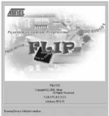
Figure 24: Splash Screen
- After a few seconds, the Splash screen is replaced by the "Atmel - Flip" window:

Figure 25: Atmel – Flip Window
- Press the keyboard shortcut key F2 (or select the "Select" command from the Device menu, or press the integrated circuit icon in the upper right corner of the window).
The "Device Selection" window appears:

Figure 26: Device Selection Window
- Click the button next to the name of the device and select from the list: AT89C51RD2:

Figure 27: Selecting the Device Window
- Click OK and select "Load Hex" from the File menu.
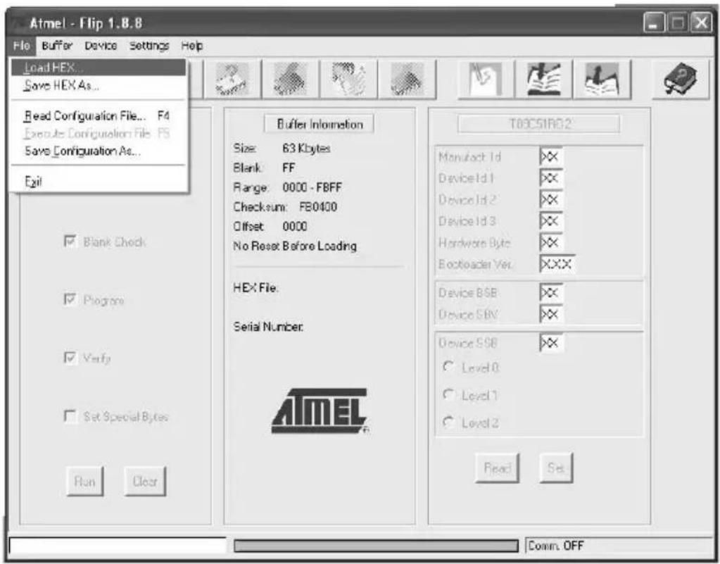
Figure 28: Loading the Hex
-
The Open File window opens. Select the correct HEX file that contains the updated version of the firmware for VP-729 (for example 44M_V1p2.hex) and click Open.
-
Press the keyboard shortcut key F3 (or select the "Communication / RS232" command from the Settings menu, or press the keys: Alt SCR).
The "RS232" window appears. Change the COM port according to the configuration of your computer and select the 9600 baud rate:

Figure 29: RS-232 Window
- Click Connect.
In the "Atmel – Flip" window, in the Operations Flow column, the Run button is active, and the name of the chip appears as the name of the third column: AT89C51RD2.
Verify that in the Buffer Information column, the "HEX File: VP729.hex" appears.

Figure 30: Atmel – Flip Window (Connected)
9. Click Run.
After each stage of the operation is completed, the check-box for that stage becomes colored green.
See also the blue progress indicator on the status bar
- When the operation is completed, all 4 check-boxes will be colored green and the status bar message: Memory Verify Pass appears:
If an error message: "Not Finished" shows, click Run again

Figure 31: Atmel – Flip Window (Operation Completed)
-
Close the "Atmel - Flip" window.
-
Disconnect the power on the VP-729.
-
If required, disconnect the rear panel AUDIO PROG. terminal block connector on the VP-729.
-
Release the rear panel AUDIO PROG. button, using a small screwdriver.
-
Connect the power to the VP-729.
Upon initialization, the new VP-729 audio software version shows in the Information menu (see Figure 22).
10 Technical Specifications
| INPUTS: | 4 x universal Y/CV, Pb/C, Pr (composite, s-Video and component) 1 Vpp/75Ω on RCA connectors;2 x UXGA on a 15-pin HD connector (VGA through UXGA)2 x HDMI connectors1 x USB connectorFor each universal input there is a corresponding (unbalanced) audio stereo input (1V nom./ 25kΩ minimum) and digital stereo S/PDIF input (32kHz to 96kHz sample frequency / 75Ω) on RCA connectorsFor each UXGA input there is a corresponding (unbalanced) audio stereo input on a 3.5mm mini jack connector |
| OUTPUTS: 1 HDMI | connector1 UXGA format on a 15-pin HD connector1 unbalanced audio stereo output (1V nom./ 50Ω) on RCA connectors1 digital stereo S/PDIF output (32kHz to 96kHz sample frequency / 75Ω) on an RCA connector |
| COMPLIANCE WITH HDMI STANDARD: | Supports HDMI and HDCP |
| OUTPUT RESOLUTIONS: | Native HDMI, 640x480x60Hz, 640x480x75Hz, 800x600x50Hz, 800x600x60Hz, 800x600x75Hz, 1024x768x50Hz, 1024x768x60Hz, 1024x768x75Hz, 1280x768x50Hz, 1280x768x60Hz, 1280x720x60Hz, 1280x800x60Hz, 1280x1024x50Hz, 1280x1024x60Hz, 1280x1024x75Hz, 1366x768x50Hz, 1366x768x60Hz, 1400x1050x50Hz, 1400x1050x60Hz, 1600x1200x50Hz, 1600x1200x60Hz, 1680x1050x60Hz, 1920x1080x60Hz, 1920x1200x60Hz, 480px60Hz, 576px60Hz, 720px50Hz, 720px60Hz, 1080ix50Hz, 1080ix60Hz, 1080px50Hz, 1080px60Hz, 720x480x59.94Hz, 1280x720x59.94Hz, 1920x1080ix59.94Hz, 1920x1080x23.98Hz, 1920x1080x29.97Hz, 1920x1080x59.94Hz or Custom |
| CONTROL: | Front panel buttons / OSD, IR remote control, RS-232 on a 9-pin D-sub connector, Ethernet |
| ADDITIONAL CONTROLS: | Picture-In-Picture: Video-in- Graphics (or vice versa), Picture-and-Picture or Split Screen (two images side-by-side), freeze, zoom, different selectable vertical refresh rates, Video and Audio ProcAmp control, output image scaling and aspect ratio change, EDID capture, text overlay, slide show |
| POWER SOURCE: | 100-240V AC, 50/60Hz, 30VA automatic power supply |
| DIMENSIONS: | 19" (W), 9.3" (D) 1U (H) rack mountable |
| WEIGHT: 3kg (6.6) | bs) approx. |
| ACCESSORIES: | Null-modem adapter, rack "ears", IR remote control, 2 sets of C-SF/2RVM-0.5 cables, power cord, control application program via RS-232 (PC) and via Ethernet (i-Phone® and PC) |
| Specifications are subject to change without noticeFor the most updated resolution list, go to our Web site at http://www.kramerelectronics.com | |
Technical Specifications of the RGBHV / RGBS (PC) / RGsB (PC) Input Signal
| Resolution | Vertical Frequency (Hz) | Notes | Resolution | Vertical Frequency (Hz) | Notes |
| 640x480 | 60 | 1152x870 | 75 | ||
| 640x480 | 67 | Mac13 | 1152x900 | 66 | Mac21 |
| 640x480 | 72 | 1152x900 | 76 | Sun | |
| 640x480 | 75 | 1280x720 | 60 | Sun | |
| 640x480 | 85 | 1280x800 | 60 | ||
| 720x400 | 70 | 1280x960 | 60 | ||
| 720x400 | 85 | 1280x960 | 85 | ||
| 800x600 | 56 | 1280x768 | 60 | ||
| 800x600 | 60 | 1280x1024 | 60 | ||
| 800x600 | 72 | 1280x1024 | 75 | ||
| 800x600 | 75 | 1280x1024 | 76 | ||
| 800x600 | 85 | 1280x1024 | 85 | Sun | |
| 832x624 | 75 | Mac16 | 1366x768 | 60 | |
| 1024x768 | 60 | 1440x900 | 60 | ||
| 1024x768 | 70 | 1400x1050 | 60 | ||
| 1024x768 | 75 | 1400x1050 | 75 | ||
| 1024x768 | 75 | Mac19 | 1600x1200 | 60 | 1600x1200 |
| 1024x768 | 85 | 1680x1050 | 60 | 1680x1050 | |
| 1024x800 | 84 | Sun | 1920x1080 | 60 | 1920x1080 |
| 1152x864 | 75 | 1920x1200 | 60 | 1920x1200 |
Technical Specifications of the HDMI Input Signal (for RGB Colorspace)
| Resolution | Vertical Frequency (Hz) | Notes | Resolution | Vertical Frequency (Hz) | Notes |
| 640x480 | 60 | 1152x870 | 75 | Mac21 | |
| 640x480 | 67 | Mac13 | 1152x900 | 66 | Sun |
| 640x480 | 72 | 1152x900 | 76 | Sun | |
| 640x480 | 75 | 1280x720 | 60 | ||
| 640x480 | 85 | 1280x800 | 60 | ||
| 720x400 | 70 | 1280x960 | 60 | ||
| 720x400 | 85 | 1280x960 | 85 | ||
| 800x600 | 56 | 1280x768 | 60 | ||
| 800x600 | 60 | 1280x1024 | 60 | ||
| 800x600 | 72 | 1280x1024 | 75 | ||
| 800x600 | 75 | 1280x1024 | 76 | ||
| 800x600 | 85 | 1280x1024 | 85 | Sun | |
| 832x624 | 75 | Mac16 | 1366x768 | 60 | |
| 1024x768 | 60 | 1400x1050 | 60 | ||
| 1024x768 | 70 | 1400x1050 | 75 | ||
| 1024x768 | 75 | 1440x900 | 60 | ||
| 1024x768 | 75 | Mac19 | 1600x1200 | 60 | |
| 1024x768 | 85 | 1680x1050 | 60 | ||
| 1024x800 | 84 | Sun | 1920x1080 | 60 | |
| 1152x864 | 75 | 1920x1200 | 60 |
Technical Specifications of the Y/C, Video Signal
| Standard | NTSC, NTSC4.43, PAL, PAL-M, PAL-N, SECAM, PAL-60 |
Technical Specifications of the HDMI Signal (for RGB or YUV Colorspace)
| Resolution | Vertical Frequency (Hz) | Notes |
| 1080i 60 YPbPr | ||
| 1080i 50 YPbPr | ||
| 1080p 60 YPbPr | ||
| 1080p 50 YPbPr | ||
| 1080P 24fps YPbPr | ||
| 720p 60 YPbPr | ||
| 720p 50 YPbPr | ||
| 480i 60 YPbPr | ||
| 480p 60 YPbPr | ||
| 576i 50 YPbPr | ||
| 576p 50 YPbPr |
Technical Specifications of the Component Input Signal
| Resolution | Vertical Frequency (Hz) | Remark |
| 1080i 60 YPbPr | ||
| 1080i 50 YPbPr | ||
| 1080p 60 YPbPr | ||
| 1080p 50 YPbPr | ||
| 720p 60 YPbPr | ||
| 720p 50 YPbPr | ||
| 480i 60 YPbPr | ||
| 480p 60 YPbPr | ||
| 576i 50 YPbPr | ||
| 576p 50 YPbPr |
| Technical Specifications of the RGBHV/Comp/YPbPr Output Signal | |
| Resolution Vertical Frequency (Hz) | |
| 640x480 60 | |
| 640x480 75 | |
| 800x600 50 | |
| 800x600 60 | |
| 800x600 75 | |
| 1024x768 50 | |
| 1024x768 60 | |
| 1024x768 75 | |
| 1280x720 60 | |
| 1280x768 50 | |
| 1280x768 60 | |
| 1280x800 60 | |
| 1280x1024 50 | |
| 1280x1024 60 | |
| 1280x1024 75 | |
| 1366x768 50 | |
| 1366x768 60 | |
| 1400x1050 50 | |
| 1400x1050 60 | |
| 1600x1200 50 | |
| 1600x1200 60 | |
| 1920x1080 60 | |
| 1920x1200 60 | |
| 1680x1050 60 | |
| 1080i 60 | |
| 1080i 50 | |
| 720p 60 | |
| 720p 50 | |
| 480p 60 | |
| 576p 50 | |
| 1080p 50 | |
| 1080p 60 | |
| 480p 59.94 | |
| 720p 59.94 | |
| 1080i 59.94 | |
| 1080p 23.98 | |
| 1080p 29.97 | |
| 1080p 59.94 | |
| Technical Specifications of the HDMI/DVI/RGB Output Signal | |
| Resolution Vertical Frequency (Hz) | |
| 640x480 60 | |
| 640x480 75 | |
| 800x600 50 | |
| 800x600 60 | |
| 800x600 75 | |
| 1024x768 50 | |
| 1024x768 60 | |
| 1024x768 75 | |
| 1280x720 60 | |
| 1280x768 50 | |
| 1280x768 60 | |
| 1280x800 60 | |
| 1280x1024 50 | |
| 1280x1024 60 | |
| 1280x1024 75 | |
| 1366x768 50 | |
| 1366x768 60 | |
| 1400x1050 50 | |
| 1400x1050 60 | |
| 1600x1200 50 | |
| 1600x1200 60 | |
| 1920x1080 60 | |
| 1920x1200 60 | |
| 1680x1050 60 | |
| 1080i 60 | |
| 1080i 50 | |
| 720p 60 | |
| 720p 50 | |
| 480p 60 | |
| 576p 50 | |
| 1080p 50 | |
| 1080p 60 | |
| 1080p 24 | |
| 480p 59.94 | |
| 720p 59.94 | |
| 1080i 59.94 | |
| 1080p 23.98 | |
| 1080p 29.97 | |
| 1080p 59.94 | |
11 VP-729 Communication Protocol
Serial Configuration:
Baud rate: 9600 (Bits per second)
Data bits: 8bits
Parity: None
Stop bits: 1bit
Communication confirmation:
Send: CR
Reply: CR>
Set Command:
Send: Y■Control_Type■Function■Param■CR
Reply: Z■Control_Type■Function■Param■CR>
Get Command:
Send: Y■Control_Type■Function■CR
Reply: Z■Control_Type■Function■Param■CR>
Example: set Input 1 Source Type to Component
Send: Y■0■0■0■CR
Reply: Z■0■0■0■CR>
Example: get current Input 1 Source Type
Send: Y■1■0■CR
Reply: Z■1■0■0■CR >
Definition:
■: ASCII Code 0x20
CR: Ascii Code 0x0D

Go to our Web site at http://www.kramerelectronics.com to check for the latest VP-729 communication protocol.
| Control Set | Type Get | Function | Parameter Description | |
| 0 1 0 | 0: Input 11: Input 22: Input 33: Input 44: VGA 15: VGA 26: HDMI 17: HDMI 28: USB | Input Source | ||
| 0 1 1 | 0: Component1: YC2: Video | Input 1 Source Type | ||
| 0 1 2 | 0: Component1: YC2: Video | Input 2 Source Type | ||
| 0 1 3 | 0: Component1: YC2: Video | Input 3 Source Type | ||
| 0 1 4 | 0: Component1: YC2: Video | Input 4 Source Type | ||
| 0 1 5 | 0: Auto1: RGB2: YUV | Input Color Format | ||
| 0 1 6 | 0: Auto1: NTSC2: PAL3: PAL-M4: PAL-N5: NTSC 4.436: SECAM7: PAL-60 | Input Video Standard | ||
| 0 | 1 | 7 | 1 ~ 50 | Input H-Position |
| 0 | 1 | 8 | 2 ~ 50 | Input V-Position |
| 0 1 9 0 | ~ 50 | Input Frequency | ||
| 0 | 1 | 10 | 0 ~ 31 | Input Phase |
| 0 | - | 11 | N/A | Input Auto Image |
| 0 | 1 | 12 | 0~100 | Picture Brightness |
| 0 | 1 | 13 | 0~100 | Picture Contrast |
| 0 | 1 | 14 | 0~100 | Picture Color |
| 0 | 1 | 15 | 0~360 | Picture Hue |
| 0 | 1 | 16 | 0~100 | Picture Sharpness |
| 0 1 17 | 0: Gamma 11: Gamma 22: Gamma 33: Gamma 44: Gamma 5 | Picture Output Gamma | ||
| 0 1 18 | 0: Auto1: Video2: Film | Picture Film Mode | ||
| 0 1 19 | 0: Off1: Low2: Medium3: High | Picture Temporal NR | ||
| 0 1 20 | 0: Off1: Low2: Medium3: High | Picture Mosquito NR | ||
| 0 1 21 | 0: Off1: On | Picture Block NR | ||
| 0 1 22 | 0: Off1: Low2: Medium3: High | Picture Detail Enhancement | ||
| 0 1 23 | 0: Off1: Low2: High | Picture Luma Transition Enhance | ||
| 0 1 24 | 0: Off1: Low2: High | Picture Chroma Transition Enhance | ||
| 0 1 25 | 0 : Native HDMI1 : 640x480@60Hz2 : 640x480@75Hz3 : 800x600@50Hz4 : 800x600@60Hz5 : 800x600@75Hz6 : 1024x768@50Hz7 : 1024x768@60Hz8 : 1024x768@75Hz9 : 1280x768@50Hz10: 1280x768@60Hz11: 1280x720@60Hz12: 1280x800@60Hz13: 1280x1024@50Hz14: 1280x1024@60Hz15: 1280x1024@75Hz16: 1366x768@50Hz17: 1366x768@60Hz18: 1400x1050@50Hz19: 1400x1050@60Hz20: 1600x1200@50Hz21: 1600x1200@60Hz22: 1680x1050@60Hz23: 1920x1080@60Hz24: 1920x1200@60Hz25: 480p@60Hz26: 576p@60Hz27: 720p@50Hz28: 720p@60Hz29: 1080i@50Hz30: 1080i@60Hz31: 1080p@50Hz32: 1080p@60Hz33: 480P@59.94Hz34: 720P@59.94Hz35: 1080i@59.94Hz36: 1080P@23.98Hz37: 1080P@29.97Hz38: 1080P@59.94Hz96: Custom197: Custom298: Custom399: Custom4 | Output Resolution | ||
| 0 1 26 | 0: Auto1: HDMI2: DVI | Output HDMI Type | ||
| 0 1 27 | 0: Best Fit1: Letterbox2: Follow Output3: Virtual Wide4: Follow Input5: Custom | Aspect Ratio | ||
| 0 | 1 | 28 | -16 ~ 16 | H-Pan |
| 0 | 1 | 29 | -16 ~ 16 | V-Pan |
| 0 | 1 | 30 | -8 ~ 8 | H-Zoom |
| 0 | 1 | 31 | -8 ~ 8 | V-Zoom |
| 0 1 32 | 0: 100%1: 150%2: 200%3: 225%4: 250%5: 275%6: 300%7: 325%8: 350%9: 375%10: 400%11: Custom | Zoom | ||
| 0 1 33 | 0 ~ 32 | Custom Zoom | ||
| 0 | 1 | 34 | 0 ~ 31 | Zoom H-Pan |
| 0 | 1 | 35 | 0 ~ 31 | Zoom V-Pan |
| 0 1 36 | 0: Off1: On | PIP On/Off | ||
| 0 1 37 | 0: Picture-In-Picture1: Picture + Picture2: Split | PIP Type | ||
| 0 1 38 | 0: Input 11: Input 22: Input 33: Input 44: VGA 15: VGA 26: HDMI 17: HDMI 2 | PIP Source | ||
| 0 1 39 | 0: 1/251: 1/162: 1/93: 1/44: Custom | PIP Size | ||
| 0 | 1 | 40 | 0 ~ 128 | PIP H-Position |
| 0 | 1 | 41 | 0 ~ 128 | PIP V-Position |
| 0 | 1 | 42 | 1 ~ 256 | PIP H-Size |
| 0 | 1 | 43 | 1 ~ 256 | PIP V-Size |
| 0 1 44 | 0: Off1: On | PIP Frame | ||
| 0 1 45 | 0: Red1: Green2: Blue | PIP Frame Color | ||
| 0 1 46 | 0: Analog1: S/PDIF | Audio Input Type | ||
| 0 | 1 | 47 | -22~0~+22 | Audio Input Volume |
| 0 1 | 48Up | -100~24 Audio Output Volume | ||
| 0 - 111 | Volume | |||
| 0 - -111 | Volume Down | |||
| 0 1 49 | -36~0~+36 Audio Bass | |||
| 0 | 1 | 50 | -36~0~+36 | Audio Treble |
| 0 1 51 | -10~10 Audio Balance | |||
| 0 1 52 | 0: Off1: On | Audio Loudness | ||
| 0 1 53 | 0: Dynamic1: User Define | Audio Delay | ||
| 1 | 54 | 0~340 (2msec steps) | User Delay | |
| 0 1 55 | 0: No audio1: Input 12: Input 23: Input 34: Input 45: VGA16: VGA27: HDMI18: HDMI2 | Audio Input For USB | ||
| 0 1 56 | 0: Keystone1: Anyplace2: Rotation | Geometry Application | ||
| 0 1 57 | 0: Front1: Ceiling2: Rear3: Rear ceiling | Geometry Location | ||
| 0 | 1 | 58 | -40 ~ 40 | Geometry Horizontal Keystone |
| 0 | 1 | 59 | -30~30 | Geometry Vertical Keystone |
| 0 | 1 | 60 | -2000~2000 | Geometry Diagonal Projection – Top Left H |
| 0 | 1 | 61 | -2000~2000 | Geometry Diagonal Projection – Top Left V |
| 0 | 1 | 62 | -2000~2000 | Geometry Diagonal Projection – Top Right H |
| 0 | 1 | 63 | -2000~2000 | Geometry Diagonal Projection – Top Right V |
| 0 | 1 | 64 | -2000~2000 | Geometry Diagonal Projection – Bottom Left H |
| 0 | 1 | 65 | -2000~2000 | Geometry Diagonal Projection – Bottom Left V |
| 0 | 1 | 66 | -2000~2000 | Geometry Diagonal Projection – Bottom Right H |
| 0 | 1 | 67 | -2000~2000 | Geometry Diagonal Projection – Bottom Right V |
| 0 | - | 68 | N/A | Geometry Diagonal Projection – Reset |
| 0 | 1 | 69 | -20 ~ 20 | Geometry Pincushion/Barrel |
| 0 | 1 | 70 | -180 ~ 180 | Geometry Rotation |
| 0 | - | 71 | N/A | Geometry Reset all |
| 0 - 72 | 0: Profile 11: Profile 22: Profile 33: Profile 44: Profile 55: Profile 66: Profile 77: Profile 8 | Save Setting | ||
| 0 - 73 | 0: Profile 11: Profile 22: Profile 33: Profile 44: Profile 55: Profile 66: Profile 77: Profile 8 | Recall Setting | ||
| 0 1 74 | 0: Off1: On | Frame Lock | ||
| 0 - 75 | N/A Factory Reset | |||
| - 1 76 | N/A Firmware Revision | |||
| 0 1 77 | 0: 1400x1050x601: 1680x1050x60 | Mode Set – Mode 1 | ||
| 0 1 78 | 0: 1280x1024x751: 1280x1024x76 | Mode Set – Mode 2 | ||
| 0 1 79 | 0: Center1: Top Left2: Top Right3: Bottom Left4: Bottom Right | OSD Menu Position | ||
| 0 1 80 | 0: 5 sec1: 10 sec2: 20 sec3: 30 sec4: 60 sec5: 90 sec6: Off | OSD Time Out | ||
| 0 1 81 | 0: Off1: On2: Custom | Logo | ||
| 0 1 82 | 0: Black1: Blue | Blank Color | ||
| 0 - 83 | N/A Capture | |||
| 0 1 84 | 0: Black1: Blue2: Custom3: Disable Analog Sync | Background | ||
| 0 1 85 | 0: Off1: On | Save Lock | ||
| 0 1 86 | 0: Off1: On | Input Lock | ||
| 0 1 87 | 0: Blank & Mute1: Blank2: Mute | Blank key function | ||
| 0 1 88 | 0: Freeze & Mute1: Freeze2: Mute | Freeze key function | ||
| 0 1 89 | 0: Off1: On | Freeze | ||
| 0 1 90 | 0: Off1: On | Blank | ||
| 0 1 91 | 0: Off1: On | Power | ||
| 0 - 92 | N/A Info | |||
| 0 - 93 | N/A Menu | |||
| 0 - 94 | N/A Top | |||
| 0 - 95 | N/A Down | |||
| 0 - 96 | N/A Left | |||
| 0 - 97 | N/A Right | |||
| 0 - 98 | N/A Enter | |||
| 0 - 99 | N/A Picture | |||
| 0 - 100 | N/A Swap | |||
| 0 1 101 | 0: Off1: On | Mute | ||
| 0 1 102 | 0: Off1: On | Lock | ||
| - 1 103 | 0: 640x480 601: 640x480 67 Mac132: 640x480 723: 640x480 754: 640x480 855: 720x400 706: 720x400 857: 800x600 568: 800x600 609: 800x600 7210: 800x600 7511: 800x600 8512: 832x624 75 Mac1613: 1024x768 6014: 1024x768 7015: 1024x768 7516: 1024x768 75 Mac1917: 1024x768 8518: 1024x800 84 Sun19: 1152x864 7520: 1152x870 75 Mac2121: 1152x900 66 Sun22: 1152x900 76 Sun23: 1280x960 6024: 1280x960 8525: 1280x768 6026: 1280x1024 6027: 1280x1024 7528: 1280x1024 76 Sun29: 1280x1024 8530: 1400x1050 6031: 1400x1050 7532: 1600x1200 6033: 1680x1050 6034: 1080i 6035: 1080i 5036: 1080p 6037: 1080p 5038: 720p 6039: 720p 5040: 480i41: 480p42: 576i43: 576p44: 1280x800 60 (Reduce blank)45: 1920x1200 6046: 1920x1080 6047: 1280x720 6048: 1080p 2449: 1280x800 6050: 1440x900 6051: 1440x900 60(Reduced blanking)52: 1280x768_60 (Reduced blanking)53: 1680x1050 60(Reduce blank)54: 1366x768 6055: 1366x768_60 (Reduce blank)94: Custom195: Custom296: Custom397: Custom498: No Input detected99: other101: NTSC102: PAL103: PAL-M104: PAL-N105: NTSC 4.43106: SECAM107: PAL-60 | Main Input status | ||
| - 1 104 | 0: 640x480 601: 640x480 67 Mac132: 640x480 723: 640x480 754: 640x480 855: 720x400 706: 720x400 857: 800x600 568: 800x600 609: 800x600 7210: 800x600 7511: 800x600 8512: 832x624 75 Mac1613: 1024x768 6014: 1024x768 7015: 1024x768 7516: 1024x768 75 Mac1917: 1024x768 8518: 1024x800 84 Sun19: 1152x864 7520: 1152x870 75 Mac2121: 1152x900 66 Sun22: 1152x900 76 Sun23: 1280x960 6024: 1280x960 8525: 1280x768 6026: 1280x1024 6027: 1280x1024 7528: 1280x1024 76 Sun29: 1280x1024 8530: 1400x1050 6031: 1400x1050 7532: 1600x1200 6033: 1680x1050 6034: 1080i 6035: 1080i 5036: 1080p 6037: 1080p 5038: 720p 6039: 720p 5040: 480i41: 480p42: 576i43: 576p44: 1280x800 60 (Reduce blank)45: 1920x1200 6046: 1920x1080 6047: 1280x720 6048: 1080p 2449: 1280x800 6050: 1440x900 6051: 1440x900 60(Reduced blanking)52: 1280x768_60 (Reduced blanking)53: 1680x1050 60(Reduce blank)54: 1366x768 6055: 1366x768_60 (Reduce blank)94: Custom195: Custom296: Custom397: Custom498: No Input detected99: other101: NTSC102: PAL103: PAL-M104: PAL-N105: NTSC 4.43106: SECAM107: PAL-60 | PIP Input status | ||
| 0 | 1 | 105 | 512~3071 | Advance Input Mode: HT |
| 0 | 1 | 106 | 32~(HS-48) | Advance Input Mode: HW |
| 0 | 1 | 107 | 80~(HT-HA-12) | Advance Input Mode: HS |
| 0 1 108 | 640~1920<= (HT-92) | Advance Input Mode: HA | ||
| 0 1 109 | 0: Negative polarity1: Positive polarity | Advance Input Mode: HP | ||
| 0 | 1 | 110 | 384~2047 | Advance Input Mode: VT |
| 0 | 1 | 111 | 2~(HS-13) | Advance Input Mode: VW |
| 0 | 1 | 112 | 15~(VT-VA-1) | Advance Input Mode: VS |
| 0 1 113 | 480~1200<= (VT-16) | Advance Input Mode: VA | ||
| 0 1 114 | 0: Negative polarity1: Positive polarity | Advance Input Mode: VP | ||
| 0 | 1 | 115 | 25 < OCLK < 165 | Advance Input Mode: OCLK(Integer) |
| 0 | 1 | 116 | 25 < OCLK < 165 | Advance Input Mode: OCLK(Decimal) |
| 0 1 117 | 0: Off1: On | Advance Input Mode: Enable | ||
| 0 | - | 118 | N/A | Advance Input Mode: Save |
| 0 | 1 | 119 | 512~3071 | Advance Output Mode: HT |
| 0 | 1 | 120 | 32~(HS-48) | Advance Output Mode: HW |
| 0 | 1 | 121 | 80~(HT-HA-12) | Advance Output Mode: HS |
| 0 1 122 | 640~1920<= (HT-92) | Advance Output Mode: HA | ||
| 0 1 123 | 0: Negative polarity1: Positive polarity | Advance Output Mode: HP | ||
| 0 | 1 | 124 | 384~2047 | Advance Output Mode: VT |
| 0 | 1 | 125 | 2~(HS-13) | Advance Output Mode: VW |
| 0 | 1 | 126 | 15~(VT-VA-1) | Advance Output Mode: VS |
| 0 1 127 | 480~1200<= (VT-16) | Advance Output Mode: VA | ||
| 0 1 128 | 0: Negative polarity1: Positive polarity | Advance Output Mode: VP | ||
| 0 | 1 | 129 | 25 < OCLK < 165 | Advance Output Mode: OCLK(Integer) |
| 0 | 1 | 130 | 25 < OCLK < 165 | Advance Output Mode: OCLK(Decimal) |
| 0 | - | 131 | N/A | Advance Output Mode: Save |
| 0 | - | 132 | N/A | Advance Output Mode: Set Current |
| 0 - 133 | N/A Volume Up | |||
| 0 - 134 | n/a Volume Down | |||
| 0 1 135 | 0: Follow Output1: Follow Input | HDCP Setting | ||
| 0 1 136 | 0:Custom11:Custom22:Custom33:Custom4 | Advance Input Mode: Custom Input | ||
| 0 1 137 | 0:Custom11:Custom22:Custom33:Custom4 | Advance Output Mode: Custom Output | ||
| 0 1 138 | 0: Off1: On | Overscan | ||
| 0 1 139 | 0: Seamless1: Fast | Switching Mode | ||
| 0 1 140 | 0: Manual1: Auto | Auto Image Mode | ||
| 0 - 141 | N/A Slideshow Start | |||
| 0 - 142 | N/A Slideshow Stop | |||
| 0 - 143 | N/A Slideshow Pause | |||
| 0 | - | 144 | N/A | Slideshow Next |
| 0 | - | 145 | N/A | Slideshow Previous |
| 0 1 146 | 0: Min1: Low2: Mid3: Long4: Max | Slideshow | ||
| 5: Off | ||||
| 0 1 147 | 0: 1280x768x601: 1366x768x60 | Mode Set – Mode 3 | ||
| 0 1 148 | 0 : Normal1 : Bypass | HDMI1 Switching Behavior | ||
| 0 1 149 | 0 : Normal1 : Bypass | HDMI2 Switching Behavior | ||
| 0 1 150 | 0 : Input 11 : Input 22 : Input 33 : Input 44 : VGA 15 : VGA 26 : HDMI 1 | HDMI1 Audio Input | ||
| 0 1 151 | 0 : Input 11 : Input 22 : Input 33 : Input 44 : VGA 15 : VGA 26 : HDMI 2 | HDMI2Audio Input | ||
| 0 - 152 | - Custom Output Read HDMI EDID Prefer Timing | |||
| 0 1 153 | 0 : Off1 : On | HDMI1 Input HDCP On/Off | ||
| 0 1 154 | 0 : Off1 : On | HDMI2Input HDCP On/Off | ||
11.1 Error Codes Description
| Error code Description |
| ERR 1 Unknown command |
| ERR 2 Unknown function |
| ERR 3 Unavailable function |
| ERR 4 Unknown control type |
| ERR 5 Unavailable get function |
| ERR 6 Unavailable set function |
| ERR 7 Unavailable parameter |
| ERR 8 Too few arguments |
LIMITED WARRANTY
The warranty obligations of Kramer Electronics for this product are limited to the terms set forth below:
What is Covered
This limited warranty covers defects in materials and workmanship in this product.
What is Not Covered
This limited warranty does not cover any damage, deterioration or malfunction resulting from any alteration, modification, improper or unreasonable use or maintenance, misuse, abuse, accident, neglect, exposure to excess moisture, fire, improper packing and shipping (such claims must be presented to the carrier), lightning, power surges, or other acts of nature. This limited warranty does not cover any damage, deterioration or malfunction resulting from the installation or removal of this product from any installation, any unauthorized tampering with this product, any repairs attempted by anyone unauthorized by Kramer Electronics to make such repairs, or any other cause which does not relate directly to a defect in materials and/or workmanship of this product. This limited warranty does not cover cartons, equipment enclosures, cables or accessories used in conjunction with this product.
Without limiting any other exclusion herein, Kramer Electronics does not warrant that the product covered hereby, including, without limitation, the technology and/or integrated circuit(s) included in the product, will not become obsolete or that such items are or will remain compatible with any other product or technology with which the product may be used.
How Long Does this Coverage Last
Seven years as of this printing; please check our Web site for the most current and accurate warranty information.
Who is Covered
Only the original purchaser of this product is covered under this limited warranty. This limited warranty is not transferable to subsequent purchasers or owners of this product.
What Kramer Electronics will do
Kramer Electronics will, at its sole option, provide one of the following three remedies to whatever extent it shall deem necessary to satisfy a proper claim under this limited warranty:
- Elect to repair or facilitate the repair of any defective parts within a reasonable period of time, free of any charge for the necessary parts and labor to complete the repair and restore this product to its proper operating condition. Kramer Electronics will also pay the shipping costs necessary to return this product once the repair is complete.
- Replace this product with a direct replacement or with a similar product deemed by Kramer Electronics to perform substantially the same function as the original product.
- Issue a refund of the original purchase price less depreciation to be determined based on the age of the product at the time remedy is sought under this limited warranty.
What Kramer Electronics will not do Under This Limited Warranty
If this product is returned to Kramer Electronics or the authorized dealer from which it was purchased or any other party authorized to repair Kramer Electronics products, this product must be insured during shipment, with the insurance and shipping charges prepaid by you. If this product is returned uninsured, you assume all risks of loss or damage during shipment. Kramer Electronics will not be responsible for any costs related to the removal or re-installation of this product from or into any installation. Kramer Electronics will not be responsible for any costs related to any setting up this product, any adjustment of user controls or any programming required for a specific installation of this product.
How to Obtain a Remedy under this Limited Warranty
To obtain a remedy under this limited warranty, you must contact either the authorized Kramer Electronics reseller from whom you purchased this product or the Kramer Electronics office nearest you. For a list of authorized Kramer Electronics resellers and/or Kramer Electronics authorized service providers, please visit our web site at www.kramerelectronics.com or contact the Kramer Electronics office nearest you.
In order to pursue any remedy under this limited warranty, you must possess an original, dated receipt as proof of purchase from an authorized Kramer Electronics reseller. If this product is returned under this limited warranty, a return authorization number, obtained from Kramer Electronics, will be required. You may also be directed to an authorized reseller or a person authorized by Kramer Electronics to repair the product.
If it is decided that this product should be returned directly to Kramer Electronics, this product should be properly packed, preferably in the original carton, for shipping. Cartons not bearing a return authorization number will be refused.
Limitation on Liability
THE MAXIMUM LIABILITY OF KRAMER ELECTRONICS UNDER THIS LIMITED WARRANTY SHALL NOT EXCEED THE ACTUAL PURCHASE PRICE PAID FOR THE PRODUCT. TO THE MAXIMUM EXTENT PERMITTED BY LAW, KRAMER ELECTRONICS IS NOT RESPONSIBLE FOR DIRECT, SPECIAL, INCIDENTAL OR CONSEQUENTIAL DAMAGES RESULTING FROM ANY BREACH OF WARRANTY OR CONDITION, OR UNDER ANY OTHER LEGAL THEORY. Some countries, districts or states do not allow the exclusion or limitation of relief, special, incidental, consequential or indirect damages, or the limitation of liability to specified amounts, so the above limitations or exclusions may not apply to you.
Exclusive Remedy
TO THE MAXIMUM EXTENT PERMITTED BY LAW, THIS LIMITED WARRANTY AND THE REMEDIES SET FORTH ABOVE ARE EXCLUSIVE AND IN LIEU OF ALL OTHER WARRANTIES, REMEDIES AND CONDITIONS, WHETHER ORAL OR WRITTEN, EXPRESS OR IMPLIED. TO THE MAXIMUM EXTENT PERMITTED BY LAW, KRAMER ELECTRONICS SPECIFICALLY DISCLAIMS ANY AND ALL IMPLIED WARRANTIES, INCLUDING, WITHOUT LIMITATION, WARRANTIES OF MERCHANTABILITY AND FITNESS FOR A PARTICULAR PURPOSE. IF KRAMER ELECTRONICS CANNOT LAWFULLY DISCLAIM OR EXCLUDE IMPLIED WARRANTIES UNDER APPLICABLE LAW, THEN ALL IMPLIED WARRANTIES COVERING THIS PRODUCT, INCLUDING WARRANTIES OF MERCHANTABILITY AND FITNESS FOR A PARTICULAR PURPOSE, SHALL APPLY TO THIS PRODUCT AS PROVIDED UNDER APPLICABLE LAW.
IF ANY PRODUCT TO WHICH THIS LIMITED WARRANTY APPLIES IS A "CONSUMER PRODUCT" UNDER THE MAGNUSON-MOSS WARRANTY ACT (15 U.S.C.A. §2301, ET SEQ.) OR OTHER APPLICABLE LAW, THE FOREGOING DISCLAIMER OF IMPLIED WARRANTIES SHALL NOT APPLY TO YOU, AND ALL IMPLIED WARRANTIES ON THIS PRODUCT, INCLUDING WARRANTIES OF MERCHANTABILITY AND FITNESS FOR THE PARTICULAR PURPOSE, SHALL APPLY AS PROVIDED UNDER APPLICABLE LAW.
Other Conditions
This limited warranty gives you specific legal rights, and you may have other rights which vary from country to country or state to state.
This limited warranty is void if (i) the label bearing the serial number of this product has been removed or defaced, (ii) the product is not distributed by Kramer Electronics or (iii) this product is not purchased from an authorized Kramer Electronics reseller. If you are unsure whether a reseller is an authorized Kramer Electronics reseller, please visit our Web site at www.kramerelectronics.com or contact a Kramer Electronics office from the list at the end of this document.
Your rights under this limited warranty are not diminished if you do not complete and return the product registration form or complete and submit the online product registration form. Kramer Electronics thanks you for purchasing a Kramer Electronics product. We hope it will give you years of satisfaction.

For the latest information on our products and a list of Kramer distributors, visit our Web site where updates to this user manual may be found.
We welcome your questions, comments, and feedback.
Web site: www.kramerelectronics.com
E-mail: info@kramerel.com


SAFETY WARNING
Disconnect the unit from the power supply before opening and servicing

PN: 2900-000362

Rev: 9
- VP-729 Quick Start Guide
- Step 1: Check what's in the box
- Step 2: Install the VP-729
- Step 3: Connect inputs and outputs
- Step 4: Connect the power
- Step 5: Operate via the front panel buttons and the remote control transmitter
- Step 6. Set the inputs
- Step 7: Set the output resolution
- Contents
- Introduction 1
- Getting Started 2
- Overview 3
- Installing in a Rack 8
- Figures
- Introduction
- Getting Started
- Achieving the Best Performance
- Recycling Kramer Products
- Overview
- The VP-729 features include:
- Defining the VP-729 Presentation Switcher/Scaler
- Installing in a Rack
- CAUTION!
- To rack-mount a machine:
- Note:
- Connecting the VP-729
- Connect the video sources:
- Connect the unbalanced stereo or digital audio sources:
- Connect the video outputs:
- Connecting a PC
- Connecting the VP-729 via the ETHERNET Port
- Presentation Switcher / Scaler Buttons
- Switching an Input
- The PIP Button Feature
- Activating the PIP Feature
- Selecting the PIP Source
- Toggling between the PIP and the Screen Source (Swap)
- Locking and Unlocking the Front Panel
- To lock the VP-729:
- To unlock the VP-729:
- The Infrared Remote Control Transmitter
- Configuring the VP-729 via the OSD MENU Screens
- The Input Screen
- Reading JPEG Files
- To read JPEG files:
- The Picture Screen
- The Output Screen
- Selecting the Correct Aspect Ratio
- The PIP Screen
- The Audio Screen
- The Geometry Screen
- The Setup Screen
- The Slideshow Feature
- The Advanced Setup Screen
- The OSD Screen Functions
- The Misc Screen functions
- The Input Functions Screen
- The Output Functions Screen
- The Info Screen
- Using Text Overlay
- Audio Flash Memory Upgrade
- Downloading from the Internet
- Connecting the PC to the RS-232 Port
- Upgrading the Audio Firmware
- Click Run.
- Technical Specifications
- VP-729 Communication Protocol
- Serial Configuration:
- Communication confirmation:
- Set Command:
- Get Command:
- Definition:
- Error Codes Description
- LIMITED WARRANTY
- What is Covered
- What is Not Covered
- How Long Does this Coverage Last
- Who is Covered
- What Kramer Electronics will do
- What Kramer Electronics will not do Under This Limited Warranty
- How to Obtain a Remedy under this Limited Warranty
- Limitation on Liability
- Exclusive Remedy
- Other Conditions
- SAFETY WARNING
Brand : Kramer
Model : ProScale VP-729
Category : Scale