
Alero ALR-AMP - Receiver AMX - Free user manual and instructions
Find the device manual for free Alero ALR-AMP AMX in PDF.


| Product Type | 8-Zone Power Amplifier |
| Brand | AMX |
| Model | Alero ALR-AMP-8 (FG1104-01) |
| Channels | 16 channels in 8 stereo zones; each zone can be bridged |
| Output Power (Stereo) | 80W per channel at 4 ohms (0.03% THD+N, 20Hz-20kHz) |
| Output Power (Bridged) | 160W per channel at 8 ohms (0.04% THD+N, 20Hz-20kHz) |
| Amplifier Technology | Class D (ICEpower) |
| Frequency Response | ±0.4 dB, 10Hz-20kHz, all loads |
| Total Harmonic Distortion + Noise | 0.003% at 4Ω, SE, 100Hz, 1W |
| Dynamic Range | 110 dBA (SE), 115 dBA (BTL) |
| Input Impedance | 47 kΩ |
| Audio Inputs | 16 RCA/phono (stereo pairs for 8 zones) |
| Speaker Outputs | 16 captive-wire terminals (2-pin per channel) |
| Control I/O | 10-pin captive-wire port (signal sense, 12V trigger, 3-5V trigger, thermal/OC monitor) |
| Power Supply | Universal mains 100-240VAC, 50-60Hz |
| Power Consumption (Standby) | < 0.25W |
| Dimensions (H x W x D) | 1.7" x 16.7" x 8.98" (44 x 424 x 228 mm) |
| Weight | 10.98 lbs (4.1 kg) |
| Rack Mount | 1U, fits standard 19" rack (included ears) |
| Cooling | Two low-noise fans, side panels |
| Operating Temperature | 32° - 113°F (0° - 45°C) |
| Certifications | FCC, CE, UL, IEC, PSE, C-TICK |
| Compliance | RoHS2, WEEE, Low Voltage Directive, EMC |
| Warranty | See AMX Warranty and Return Policy at www.amx.com |
Frequently Asked Questions - Alero ALR-AMP AMX
User questions about Alero ALR-AMP AMX
0 question about this device. Answer the ones you know or ask your own.
Ask a new question about this device
Download the instructions for your Receiver in PDF format for free! Find your manual Alero ALR-AMP - AMX and take your electronic device back in hand. On this page are published all the documents necessary for the use of your device. Alero ALR-AMP by AMX.
USER MANUAL Alero ALR-AMP AMX
IMPORTANT SAFETY INSTRUCTIONS
-
READ these instructions.
-
KEEP these instructions.
-
HEED all warnings.
-
FOLLOW all instructions.
-
DO NOT use this apparatus near water.
-
CLEAN ONLY with dry cloth.
-
DO NOT block any ventilation openings. Install in accordance with the manufacturer's instructions.
-
DO NOT install near any heat sources such as radiators, heat registers, stoves, or other apparatus (including amplifiers) that produce heat.
-
DO NOT defeat the safety purpose of the polarized or grounding type plug. A polarized plug has two blades with one wider than the other. A grounding type plug has two blades and a third grounding prong. The wider blade or the third prong are provided for your safety. If the provided plug does not fit into your outlet, consult an electrician for replacement of the obsolete outlet.
-
PROTECT the power cord from being walked on or pinched, particularly at plugs, convenience receptacles, and the point where they exit from the apparatus.
-
ONLY USE attachments/accessories specified by the manufacturer.

-
USE ONLY with a cart, stand, tripod, bracket, or table specified by the manufacturer, or sold with the apparatus. When a cart is used, use caution when moving the cart/apparatus combination to avoid injury from tip-over.
-
UNPLUG this apparatus during lightning storms or when unused for long periods of time.
-
REFER all servicing to qualified service personnel. Servicing is required when the apparatus has been damaged in any way, such as power-supply cord or plug is damaged, liquid has been spilled or objects have fallen into the apparatus, the apparatus has been exposed to rain or moisture, does not operate normally, or has been dropped.
-
DO NOT expose this apparatus to dripping or splashing and ensure that no objects filled with liquids, such as vases, are placed on the apparatus.
-
To completely disconnect this apparatus from the AC Mains, disconnect the power supply cord plug from the AC receptacle.
-
Where the mains plug or an appliance coupler is used as the disconnect device, the disconnect device shall remain readily operable.
-
DO NOT overload wall outlets or extension cords beyond their rated capacity as this can cause electric shock or fire.

The exclamation point, within an equilateral triangle, is intended to alert the user to the presence of important operating and maintenance (servicing) instructions in the literature accompanying the product.

The lightning flash with arrowhead symbol within an equilateral triangle is intended to alert the user to the presence of uninsulated "dangerous voltage" within the product's enclosure that may be of sufficient magnitude to constitute a risk of electrical shock to persons.

ESD Warning: The Icon to the left indicates text regarding potential danger associated with the discharge of static electricity from an outside source (such as human hands) into an integrated circuit, often resulting in damage to the circuit.
WARNING: To reduce the risk of fire or electrical shock, do not expose this apparatus to rain or moisture.
WARNING: No naked flame sources - such as candles - should be placed on the product.
WARNING: Equipment shall be connected to a MAINS socket outlet with a protective earthing connection.
WARNING: To reduce the risk of electric shock, grounding of the center pin of this plug must be maintained.
COPYRIGHT NOTICE
AMX© 2015, all rights reserved. No part of this publication may be reproduced, stored in a retrieval system, or transmitted, in any form or by any means, electronic, mechanical, photocopying, recording, or otherwise, without the prior written permission of AMX. Copyright protection claimed extends to AMX hardware and software and includes all forms and matters copyrightable material and information now allowed by statutory or judicial law or herein after granted, including without limitation, material generated from the software programs which are displayed on the screen such as icons, screen display looks, etc. Reproduction or disassembly of embodied computer programs or algorithms is expressly prohibited.
LIABILITY NOTICE
No patent liability is assumed with respect to the use of information contained herein. While every precaution has been taken in the preparation of this publication, AMX assumes no responsibility for error or omissions. No liability is assumed for damages resulting from the use of the information contained herein. Further, this publication and features described herein are subject to change without notice.
AMX WARRANTY AND RETURN POLICY
The AMX Warranty and Return Policy and related documents can be viewed/downloaded at www.amx.com.
ESD WARNING

To avoid ESD (Electrostatic Discharge) damage to sensitive components, make sure you are properly grounded before touching any internal materials.
When working with any equipment manufactured with electronic devices, proper ESD grounding procedures must be followed to make sure people, products, and tools are as free of static charges as possible. Grounding straps, conductive smocks, and conductive work mats are specifically designed for this purpose.
Anyone performing field maintenance on AMX equipment should use an appropriate ESD field service kit complete with at least a dissipative work mat with a ground cord and a UL listed adjustable wrist strap with another ground cord

WARNING: Do Not Open! Risk of Electrical Shock. Voltages in this equipment are hazardous to life. No user-serviceable parts inside. Refer all servicing to qualified service personnel.
Place the equipment near a main power supply outlet and make sure that you can easily access the power breaker switch.
WARNING: This product is intended to be operated ONLY from the voltages listed on the back panel or the recommended, or included, power supply of the product. Operation from other voltages other than those indicated may cause irreversible damage to the product and void the products warranty. The use of AC Plug Adapters is cautioned because it can allow the product to be plugged into voltages in which the product was not designed to operate. If the product is equipped with a detachable power cord, use only the type provided with your product or by your local distributor and/or retailer. If you are unsure of the correct operational voltage, please contact your local distributor and/or retailer.
FCC AND CANADA EMC COMPLIANCE INFORMATION:
This device complies with part 15 of the FCC Rules. Operation is subject to the following two conditions:
(1) This device may not cause harmful interference, and (2) this device must accept any interference received, including interference that may cause undesired operation.
NOTE: This equipment has been tested and found to comply with the limits for a Class B digital device, pursuant to part 15 of the FCC Rules. These limits are designed to provide reasonable protection against harmful interference in a residential installation. This equipment generates, uses and can radiate radio frequency energy and, if not installed and used in accordance with the instructions, may cause harmful interference to radio communications. However, there is no guarantee that interference will not occur in a particular installation. If this equipment does cause harmful interference to radio or television reception, which can be determined by turning the equipment off and on, the user is encouraged to try to correct the interference by one or more of the following measures:
•Reorient or relocate the receiving antenna.
- Increase the separation between the equipment and receiver.
- Connect the equipment into an outlet on a circuit different from that to which the receiver is connected.
- Consult the dealer or an experienced radio/TV technician for help.
Approved under the verification provision of FCC Part 15 as a Class B Digital Device.
Caution: Changes or modifications not expressly approved by the manufacturer could void the user's authority to operate this device.
CAN ICES-3 (B)/NMB-3(B)
WIRELESS TRANSMITTER COMPLIANCE INFORMATION:
The term "IC:" before the radio certification number only signifies that Industry Canada technical specifications were met.
This device complies with part 15 of the FCC Rules and the applicable Industry Canada license-exempt Operation is subject to the following two conditions: (1) this device may not cause harmful interference, and (2) this device must accept any interference, including interference that may cause undesired operation of the device.
This equipment complies with FCC and IC radiation exposure limits set forth for an uncontrolled environment. This equipment should be installed and operated with minimum distance 20cm between the radiator and your body. This transmitter must not be co-located or operating in conjunction with any other antenna or transmitter.
Eligible to bear the CE mark; Conforms to European Union Low Voltage Directive 2006/95/EC; European Union EMC Directive 2004/108/EC; European Union Restriction of Hazardous Substances Recast (RoHS2) Directive 2011/65/EU; European Union WEEE (recast) Directive 2012/19/EU; European Union Radio and Telecommunications Terminal Equipment (R&TTE) Directive 1999/5/EC.
You may obtain a free copy of the Declaration of Conformity by visiting http://www.amx.com/techcenter/certifications.asp.
WEEE NOTICE:
 | This appliance is labeled in accordance with European Directive 2012/19/EU concerning waste of electrical and electronic equipment (WEEE). This label indicates that this product should not be disposed of with household waste. It should be deposited at an appropriate facility to enable recovery and recycling. |
CHINA COMPLIANCE INFORMATION:

This device is designed and evaluated under the condition of non-tropical climate; it can only be used in locations in non-tropical climate areas. Using the device in tropical climate areas could result in a potential safety hazard.

This device is designed and evaluated under the condition of altitude below 2000 meters above sea level; it can only be used in locations below 2000 meters above sea level. Using the device above 2000 meters could result in a potential safety hazard.
Table of Contents
Alero ALR-AMP-8 8 Zone Power Amplifier ....7
Overview 7
Common Application 7
Product Features 7
Product Specifications 7
Front Panel Components (LEDs)....8
POWER LED (Green/Red) 8
OC/CLIP LED (Yellow/Red) 8
THERMAL LED (Red) 8
Rear Panel Components 9
System Diagram....9
Controlling the Alero ALR-AMP-8 9
Installation 10
Mounting the Alero into an Equipment Rack.... 10
Ventilation.... 10
Rack Mount Safety Instructions 10
Wiring and Connections 10
Connecting Audio Source Devices.... 10
Audio (Signal) Inputs 10
SE/BTL (Stereo/Bridge Mode) Switches (1-8).... 10
Connecting Input Devices in Stereo Mode 11
Connecting Input Devices in Bridge Mode 11
Connecting Speakers 12
Speaker Output Connectors 12
Connecting Speakers in Stereo Mode 13
Connecting Speakers in Bridge Mode 14
I/O (Control Input) Port 15
Pins 7 & 8 - Thermal Overload and OC (Overcurrent) Monitor Indicators 17
Pin 9 - On Signal Output / 12V Trigger 17
On Signal Output.... 17
12V Trigger 18
Pin 10 - Status GND ...... 18
On/Off Control (12V Trigger, 3-5V Trigger and Signal Sense) 18
Enabling and Disabling Zones 18
Table of Contents
Applying Power to the Alero Amplifier 19
AC Power Plug Connector.... 19
Entering Standby Mode 19
NetLinx Programming Example:
On Signal, OC and Thermal Functions ....20
Overview 20
Alero ALR-AMP-8 8 Zone Power Amplifier
Overview
The Alero ALR-AMP-8 8-Zone Power Amplifier (FG1104-01) features 16 distribution channels of true audiophile quality sound and highly efficient, heat-dissipating Class D power amplification – all smartly designed to fit into a compact 1RU chassis. Alero perfectly complements the AMX Precis DSP for a completely unified, whole-home distributed audio source switching and amplification solution.
Whether you are listening to music in your home theater, your kitchen or by the pool – the experience is the same – life changing. AMX equipped Alero with the same switching amplification technologies by ICEpower®, an independent subsidiary of Bang & Olufsen a/s, that are also used by several of the world's premium home audio and automotive audio manufacturers. And it's engineered to perform as well as it sounds.

FIG. 1 Alero ALR-AMP-8 Audio Amplifier
Common Application
The Alero Power Amplifier is ideal for discerning audiophiles who demand the highest quality of multi-room distributed audio.
Product Features
- Audiophile Performance – Features the same switching amplification technologies by ICEpower® that are also used by several of the world's premium home audio and automotive audio manufacturers
- 16 Channels at your Beck and Call – No matter how large or far reaching the property, you have 16 channels available for all kinds of zoning configurations
• Available Output Power – 80 watts per channel at 4 ohms / 160 watts at 8 ohms bridged - More Room in the Rack – At just 1RU high, Alero offers you the ability to install more components in the same rack
- Cool Running – Class D amplifier technology ensures efficient heat dissipation and low power consumption
Product Specifications
| Alero ALR-AMP-8 Product Specifications | |
| General | |
| Number of channels 16 channels in 8 stereo Zones; each Zone can be bridged. | |
| Output power • 80W per Ch. in SE, 4Ω (0.03%THD+N, 20Hz - 20kHz)• 1 6 0 W p er C h . i n B T L-,20kHz (0.04%THD+N, 20Hz | |
| Signal sense | Audio input sense, 12V trigger and 3-5V trigger |
| Standby power consumption | Less than 0.25W |
| Audio | |
| Amplifier | • Amplifier Gain: The audio gain (20Hz to 20kHz) is 25.8dB ±0.5dB.• Amplifier Input: The amplifier has a Single Ended input. Maximum input voltage without clipping is 1Vrms.• Amplifier Output: The amplifier uses a Single Ended output stage. Thus the power output is GND referenced.Maximum output voltage without clipping is 28Vp. |
| THD + N | 0.003%, 4Ω, SE, f=100Hz, Po=1W |
| Dynamic range | 110dBA SE, 115dBA BTL |
| Idle noise | 50uV, A-weighted, 20Hz-20kHz |
| Upper bandwidth, -3 dB | • 100 kHz, 4Ω, SE• 1 2 0 k Hz , 8 Ω,SE |
| Frequency response | ±0.4 dB, 10Hz- 20kHz, all loads |
| Input impedance | 47K Ω |
| Output serial impedance | 30m Ω, f≤1kHz |
| Alero ALR-AMP-8 Product Specifications (Cont.) | |
| AC Mains Power | |
| AC mains power Universal Mains 100- | 240VAC, 50-60Hz |
| Fuse rating T6.3A_H 250V | |
| Power connection IEC 320 C13 power connector with 3-pole detachable power cord | |
| Thermal | |
| Environmental operating temperature | 32° - 113°F/0° - 45°C |
| Thermal dissipation Two low noise fans mounted in side panels | |
| Thermal dissipation (heat losses) • 0.23 W/ 0.8 BTU/hr, standby• 40 W/ 136.5 BTU/hr, idle, all ch.• 100 W/ 341 BTU/hr, max output power, all ch. driven | |
| Physical | |
| Height 1U, 1.7 Inches/44 mm (1 RU) | |
| Width 16.7 inches (424mm) - Fits in a standard 19" equipment rack | |
| Depth | 8.98" (228mm) without connectors and 9.30" (236.3mm) with connectors |
| Weight | 10.98 lbs (4.1kg) |
| Certifications | • FCC• CE• UL• IEC• PSE• C-TICK |
Front Panel Components (LEDs)
The front panel features three LEDs (see FIG. 1 on page 7):
POWER LED (Green/Red)
The Power LED indicates that the current power state of the amp:
- Green indicates that the amplifier is On.
- Red indicates that the amplifier is receiving power, but is in Standby mode.
OC/CLIP LED (Yellow/Red)
The OC/CLIP LED indicates that either the current of one or more of the speaker outputs has exceeded its maximum or that the power supply is overloaded.
NOTE: The amplifier outputs are limited to 20A peak each in order to protect the power stages against overload during a short circuit, or over-current event on the output of the amplifier.
- Yellow indicates an OC (over-current) shutdown of the amplifier output.- In the case of an OC event, the amplifier will shut down to protect itself, and indicate an OC event on this LED (yellow) and the OC pin (pin 8 on the 10-pin I/O port - see page 15). An OC event can indicate a cable fault, installation fault or defective speaker.
- Red indicates an overload event with the Power Supply. The LED will light red if internal temperature sensors on the power supply sense an abnormally high temperature, or if power supply over-current/over-load/power-limit circuits are triggered. In either case, the power supply will limit the amplifier output to keep the power supply within safe limits, while keeping the music playing.
THERMAL LED (Red)
The Thermal Protection LED indicates thermal shutdown of the individual zones (amplifier boards).
- The temperatures of all the output channels are individually monitored, and if one or more of them reaches the thermal limit (105°C) then the respective Zones will shut down and go into soft start mode (Channels 1/2 = Zone 1, Channels 3/4 = Zone 2, etc), and the Thermal Protection LED will be lit.
- The other Zones will continue to be active. When the temperature has dropped below the thermal threshold, the respective Zone(s) start up again automatically.
Rear Panel Components
The rear panel provides all input, output, control and power connections (FIG. 2):
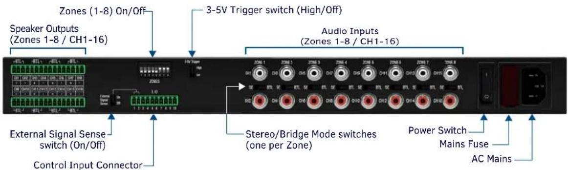
FIG. 2 ALR-AMP-8 Rear Panel
Refer to the Installation section on page 10 for connector details and wiring information.
System Diagram
FIG. 3 provides a basic system diagram showing the Alero in a NetLinx System:
![graph TD A["Touch Panel"] --> B["NetLinx Controller"] C["Stereo Audio Source Devices"] --> D["Precis DSP Audio Switcher with Volume Control"] E["Alero ALR-AMP-8"] --> F["Stereo Speaker Pairs (8 Zones)"] B --> G["Computer"] B --> H["Server"] B --> I["Server"] B --> J["Server"] B --> K["Server"] B -->…](/content/2026/05/1054937/images/083221f73063f1c2ac67ba10e112b8e470999dc5f80bb6619fe2b3fa54a3c130.jpg)
FIG. 3 Alero / NetLinx System Diagram
NOTE: Note that the Alero ALR-AMP-8 requires an external preamp for volume control.
This example shows eight stereo audio source devices connected to the Alero ALR-AMP-8, and eight stereo Zones for audio output.
- The Alero also supports a Bridge Mode (BTL) configuration. Bridge Mode converts one stereo pair into a single, stronger amplification channel. If all Zones are bridged, there are 8 channels available.
- Stereo and Bridged Zones can be mixed as necessary (see the Connecting Audio Source Devices section on page 10 for details).
Controlling the Alero ALR-AMP-8
Volume control for the Alero ALR-AMP-8 is managed by an external pre-amp / audio switcher, such as the AMX Precis DSP (Fixed Matrix Switcher with Stereo Audio with RCA Digital Volume Control and Digital Signal Processing).
The Alero ALR-AMP-8 can be powered on and off externally by using the two signals 12V trigger and 3-5V trigger. A Signal Sense function is also provided which automatically can switch on the Alero in the event of an audio signal and switch off the Alero to enter standby mode when no audio signal has been present on the signal terminals for approximately 13 minutes.
Refer to the On/Off Control (12V Trigger, 3-5V Trigger and Signal Sense) section on page 18 for details.
Installation
Mounting the Alero into an Equipment Rack
The Alero ALR-AMP-8 can be mounted in a 19" equipment rack or on a solid flat surface.
Use the included removable rack ears and removable feet for mounting.
Ventilation
NOTE: The maximum operating ambient temperature is 45° C ( 113° F).
- To ensure that the rack enclosure is adequately ventilated, there must be a minimum of 3" all around the Alero unit.
- Sufficient airflow must be achieved (by convection or forced-air cooling) to satisfy the ventilation requirements of all the items of equipment installed within the rack.
Rack Mount Safety Instructions
- Mounting of the equipment in the rack should be such that a hazardous condition is not achieved due to uneven mechanical loading.
- Consideration should be given to the connection of the equipment to the supply circuit and the effect that overloading of the circuits might have on over current protection and supply wiring. Appropriate consideration of equipment nameplate ratings should be used when addressing this concern.
- Reliable earthing of rack-mounted equipment should be maintained. Particular attention should be given to supply connections other than direct connections to the branch circuit (e.g. use of power strips).
Wiring and Connections
NOTE: All speaker wire connections must be made with the amplifier off. The amplifier must be off whenever you make changes to the input connections.
Connecting Audio Source Devices
Source Devices connect to the Audio (Signal) Inputs connectors on the rear panel. (FIG. 4):
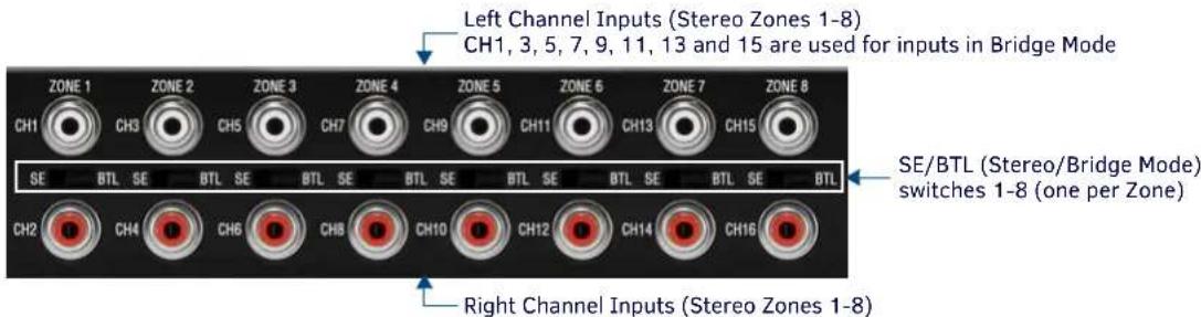
FIG. 4 Audio Input connectors (L/R pairs for 8 stereo inputs, 16 total)
- The Audio Inputs consist of 16 RCA/phono terminals; each of the single-ended input channels having a signal input and ground.
- Each Zone (1–8) consists of two channels (odd and even) that represent the left and right channels in a stereo pair. For example, CH1 and CH2 represent the left and right channels for Zone 1.
Audio (Signal) Inputs
The following table provides pinout information for the Audio Inputs:
| Audio Input Connectors - Pinout Information | |||
| PIN Function Description Type | |||
| 1 Signal + Single Ended Signal Positive Input | |||
| 2 Signal GND Single Ended Signal GND GND | |||
SE/BTL (Stereo/Bridge Mode) Switches (1-8)
The ALR-AMP-8 features eight SE/BTL slide switches (located between the two RCA/phono input connectors for each Zone - see FIG. 4). These switches provide the ability to set each of the eight Zones to either Stereo Mode (SE) or Bridge Mode (BTL). Note that by default, all Audio Inputs are set to Stereo Mode.
- Stereo Mode (SE): In Stereo Mode, both channels are used for stereo audio input. Stereo mode provides true stereo separation between the left and right channels in each Zone.
- Bridge Mode (BTL): Bridge Mode uses one input channel of the amplifier to combine the power from both channels output into one single output. In Bridge Mode, the odd channels are used for audio input and the even channels are disconnected internally.
Connecting Input Devices in Stereo Mode
Stereo input devices use both input channels (left and right) for each Zone.
- Odd-numbered channels (with white connectors) should be used to connect to the left output on the source device.
- Even-numbered channels (with red connectors) should be used to connect to the right output on the source device.
The Alero ALR-AMP-8 supports up to eight stereo input devices, each one associated with an input Zone (1-8). Note that each Zone represents a stereo pair. For example, Zone 1 consists of CH1 (left channel) and Ch2 (right channel).
There is a direct correlation between the audio inputs and the speaker outputs. For example, a stereo device connected to the Zone 1 inputs (CH1 and CH2) will output on the CH1 (left) and CH2 (right) speaker outputs (FIG. 5):
Alero INPUTS (Stereo Mode) Alero OUTPUTS (Stereo Mode)
![graph LR A["From stereo source device (left output)"] --> B["Zone 1 (CH1 and CH2) audio inputs"] C["From stereo source device (right output)"] --> B B --> D["Zone 1 (CH1 and CH2) speaker outputs"] D --> E["Left right"] D --> F["Right right"]](/content/2026/05/1054937/images/bfa9bef516d89e5a2ec34d6413698457c336052baadb878b0acbd5146b27ded1.jpg)
FIG. 5 Stereo Input Mode - Zone 1 (CH1 and CH2) is output on Speaker Outputs CH1 and CH2
NOTE: When connecting stereo input devices, verify that the Stereo/Bridge (SE/BTL) mode switch for the Zone (see FIG. 4) is set to "SE". This is the default factory setting.
See Also: Connecting Speakers in Stereo Mode on page 13.
Connecting Input Devices in Bridge Mode
In Bridge Mode, input devices connect to the left input channels only. Note that left input connectors are white, and are the odd-numbered channels (CH1, 3, 5, 7, 9, 11, 13 and 15).
There is a direct correlation between the audio inputs and the speaker outputs. For example, a bridged device connected to the Channel 1 input (CH1) will output on the CH1 (left) and CH2 (right) speaker outputs - see FIG. 6:
Alero INPUTS (Bridge Mode) Alero OUTPUTS (Bridge Mode)
![graph LR A["From bridged source device"] --> B["Zone 1 (CH1 and CH2) audio inputs"] B --> C["CH1 input"] B --> D["CH2"] D --> E["Ch1 + and CH2+ Speaker Outputs"]](/content/2026/05/1054937/images/4b980fcf67fb468da9d13b2d0f0fd0eae892b87da614da8c62d4296e0b8c62fc.jpg)
FIG. 6 Bridged Input Mode - Channel 1 is output on a single speaker connected to Speaker Outputs CH1(+) and CH2(+)
NOTE: When connecting bridged input devices, verify that the Stereo/Bridge (SE/BTL) mode switch for the Zone is set to "BTL" as shown above (FIG. 6).
See Also: Connecting Speakers in Bridge Mode on page 14.
Connecting Speakers
All speaker connections must use Class 2 Wiring.
NOTE: All speaker connections must use Class 2 Wiring. Class 2 Wiring is required due to the fact that power is above 10W per channel under normal operating conditions.
Speakers connect to the captive-wire output terminals (CH1-CH16) on the rear panel (FIG. 7): t

Odd numbered outputs = left channel (in Stereo Mode) Even numbered outputs = right channel (in Stereo Mode)
Zone 1 = CH1/CH2
Zone 2 = CH3/CH4
Zone 3 = CH5/CH6
Zone 4 = CH7/CH8
Zone 5 = CH9/CH10
Zone 6 = CH11/CH12
Zone 7 = CH13/CH14
Zone 8 = CH15/CH16
FIG. 7 Speaker (Output) Terminals (16 total, L/R pairs for eight stereo outputs)
Each Zone (1-8) consists of two channels (an L/R pair in Stereo Mode), and each Channel (1-16) uses a 2-pin captive-wire connector to connect to speakers.
NOTE: For wiring runs longer than 80 feet, 14-gauge speaker wire is recommended.
Speaker Output Connectors
The speaker output connectors consist of two 16 pin captive-wire terminals; each of the output terminals having a "+" and "-" terminal.
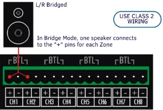
The label "BTL" on each speaker pair points to the pins that are used when connecting a single speaker to an input in Bridge Mode (see SE/BTL (Stereo/Bridge Mode) Switches (1-8) on page 10).
- See the Connecting Input Devices in Bridge Mode section on page 11 for details.
• See the Connecting Speakers section on page 12 for connection details.
The following table provides pinout information for the Speaker Output Terminals
| Speaker Output Terminals Pinout Information | |||
| PIN | Function Description Type | ||
| 1 | OUT+ | Positive balanced audio power output terminal Output | |
| 2 | OUT- | Negative balanced audio power output terminal Output | |
Connecting Speakers in Stereo Mode
NOTE: When connecting stereo speakers, verify that the Stereo/Bridge (SE/BTL) mode switch for the associated Zone (see FIG. 5 on page 10) is set to "SE".
Stereo speaker pairs use both output channels (left and right) for each Zone.
- Odd-numbered channels should be used to connect to the left speaker.
- Even-numbered channels should be used to connect to the right speaker.
The ALR-AMP-8 supports up to eight stereo speaker pairs, each one associated with a Zone (1-8).
FIG. 8 illustrates the wiring connection from both Zone output channels to a stereo speaker pair:
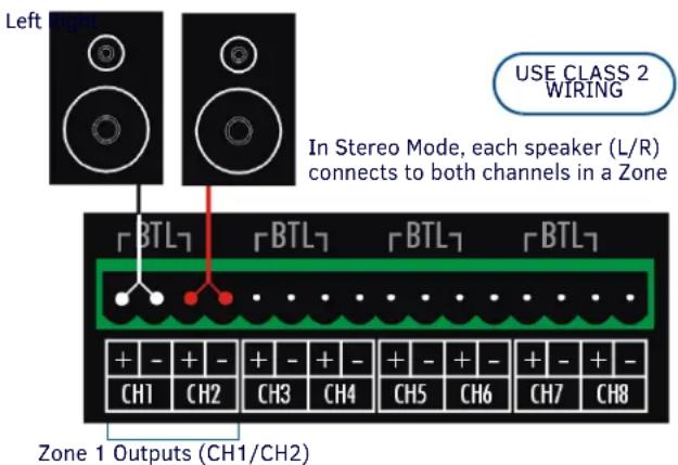
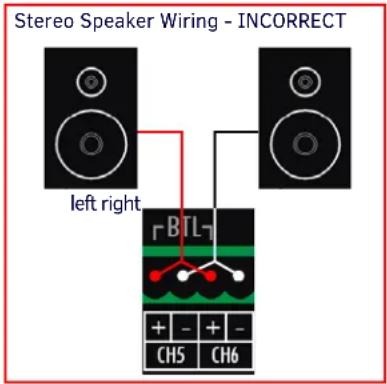
FIG. 8 Stereo Output Mode
NOTE: If incorrect wiring is used there is a risk of electrical shock and a fire hazard.
The table below illustrates the direct correlation between the audio inputs and the speaker outputs in Stereo Mode:
| Audio Inputs to Speaker Outputs - Stereo Mode | ||
| Zone A | Audio Input Connectors Speaker | Output Connectors |
| 1 CH1 | (left) / CH2 (right) CH1 (left) / CH2 (right) | |
| 2 CH3 | (left) / CH4 (right) CH3 (left) / CH4 (right) | |
| 3 CH5 | (left) / CH6 (right) CH5 (left) / CH6 (right) | |
| 4 CH7 | (left) / CH8 (right) CH7 (left) / CH8 (right) | |
| 5 CH9 | (left) / CH10 (right) CH9 (left) / CH10 (right) | |
| 6 CH11 | (left) / CH12 (right) CH11 (left) / CH12 (right) | |
| 7 CH13 | (left) / CH14 (right) CH13 (left) / CH14 (right) | |
| 8 CH15 | (left) / CH16 (right) CH15 (left) / CH16 (right) | |
See Also: Connecting Input Devices in Stereo Mode on page 11.
Connecting Speakers in Bridge Mode
NOTE: When connecting a speaker to a "bridged" input, verify that the Stereo/Bridge (SE/BTL) mode switch for the associated Zone (see FIG. 6 on page 10) is set to "BTL".
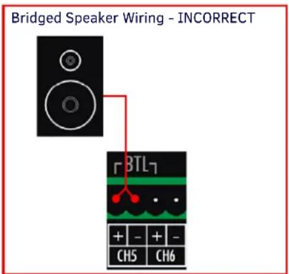
In Bridge Mode, both channels in a Zone are connected to a single speaker, via the positive ("+") pins for both output channels (labeled "BTL", as shown in FIG. 9):
Zone 1 Outputs (CH1/CH2)
FIG. 9 Bridged Output Mode
CAUTION: If incorrect wiring is used there is a risk of electrical shock and a fire hazard.
The table below illustrates the direct correlation between the audio inputs and the speaker outputs in Bridge Mode:
| Audio Inputs to Speaker Outputs - Bridge Mode | ||
| Zone | Audio Input Connectors | Speaker Output Connectors |
| 1 CH1 | (left) CH1 (+) / CH2 (+) | |
| 2 CH3 | (left) CH3 (+) / CH4 (+) | |
| 3 CH5 | (left) CH5 (+) / CH6 (+) | |
| 4 CH7 | (left) CH7 (+) / CH8 (+) | |
| 5 CH9 | (left) CH9 (+) / CH10 (+) | |
| 6 CH1 | 1 (left) CH11 (+) / CH12 (+) | |
| 7 CH1 | 3 (left) CH13 (+) / CH14 (+) | |
| 8 CH1 | 5 (left) CH15 (+) / CH16 (+) | |
See Also: Connecting Input Devices in Bridge Mode on page 11.
I/O (Control Input) Port
The 10-pin captive-wire I/O (Control Input) port is for external control and status indication (FIG. 10).

FIG. 10 10-pin I/O (Control Input) Port with External Signal Sense switch
The following table lists the pinouts for the I/O port
| 10-Pin I/O Port - Pinout Information | ||||
| PIN Function Description Type Page Reference | ||||
| 1 | Signal Sense + | Signal Sense | Input | page 15 |
| 2 | Signal GND | Single Ended Signal GND | GND | page 15 |
| 3 | 12V Trigger In | 12V Trigger Input | Input | page 16 |
| 4 | Trigger Loop Out | Trigger Loop Out | Output | page 16 |
| 5 | GND | Logic / Trigger GND | GND | page 16 |
| 6 | 3-5V Trigger | Logic Level Trigger | Input | page 16 |
| 7 | Thermal | Thermal Overload Indicator | Output | page 17 |
| 8 | OC | Overcurrent Monitor Indicator | Output | page 17 |
| 9 | On signal | On Signal Output | Output | page 17 |
| 10 | GND | Status GND | GND | page 18 |
The function of each pin on the I/O port is described below.
Pin 1 - Signal Sense
Pin 1 on the 10-pin I/O port is used for single-ended Signal Sense input (+). This pin detects an input signal from a source device when the source device is active. Pin 1 (Signal Sense +) connects to one of the source device's input cables to provide a signal to the Alero when the source device is active (FIG. 11):.
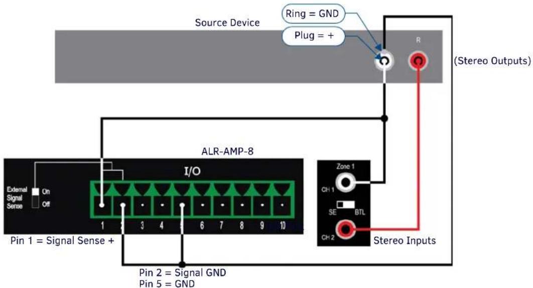
FIG. 11 PIN 1 Example - Signal Sense Connection (Unbalanced)
External Signal Sense Switch
With the External Signal Sense switch in the ON position (see FIG. 10), the amplifier is automatically turned on when an audio signal is present, and automatically placed in standby mode when no audio signal has been present on the signal terminals for approximately 13 minutes.
- Note that the example diagram in FIG. 11 indicates the Signal Sense connection tied to the Left output from the source device, but Signal Sense can come from either output.
- The amplifier will power up if a signal is applied to the signal sense input. By default, the External Signal Switch is set to the ON position.
Pin 3 - 12V (In) Trigger
The Alero can be turned On or placed in Standby mode externally via a 12V Trigger signal. A 12V trigger input is accessible via Pin 3 on the 10-pin I/O port (FIG. 12).

FIG. 12 PIN 3 Example - 12V Trigger (In) Connections
Typically, Pin 3 connects to a relay pin on a Controller's Relay port. For example, the connection shown in FIG. 12 would allow the Alero to be turned on/off programmatically via Relay #7 on the Controller.
Pin 4 - Trigger (Loop Out)
The Alero also provides a convenient way to daisy-chain a 12V trigger to other devices. Any voltage provided to Pin 3 is looped out to Pin 4 of the 10-pin I/O port (FIG. 13):

FIG. 13 PIN 4 Example - Trigger (Loop Out) Connections
Pin 4 connects to a +12V Trigger (input) on a downstream amplifier (see FIG. 12).
NOTE: Pin 3 and Pin 4 are hardwired together. Therefore, when a trigger is applied to pin 3 it will also be present at pin 4. Pin 4 will be high only if a signal is applied to Pin 3.
Pin 5 - Local/Trigger GND
Pin 5 on the 10-pin I/O port provides a ground connection for the 3-5V Logic Level Trigger. Pin 5 connects to the GND pin of an I/O port on an external controller, such as a NetLinx Central Controller.
Pin 6 - 3-5V Logic Level Trigger
The Alero can be also turned On or placed in Standby mode externally via a 3-5V Logic Level trigger signal. A 3-5V trigger input is accessible via Pin 6 on the 10-pin I/O port.
3-5V Trigger Switch
The 3-5V Trigger Switch (FIG. 14) has two selections; High and Off.
When the 3-5V Trigger Switch is set to High, the amplifier will turn on when AC mains is turned on. For example, the 3-5V Trigger switch could be set to High if the amplifier needs to be forced on without having signal sense or external trigger signals.

3-5V Trigger Switch (High/Off)
FIG. 14 3-5V Trigger Switch
Pins 7 & 8 - Thermal Overload and OC (Overcurrent) Monitor Indicators
The Thermal Overload Indicator (OUT) signal can be used to send a Thermal message from the Alero to an external controller (such as NetLinx Central Controller), if desired.
The OC (Overcurrent) Monitor Indicator (OUT) signal can be used to send an OC message from the Alero to an external controller if desired.
NOTE: The THERMAL and OC/CLIP LEDs on the front panel (see FIG. 1 on page 9) always light to indicate these conditions.
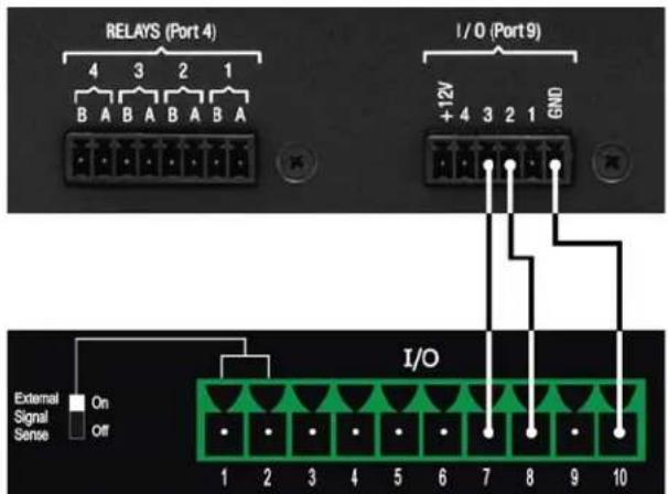
- A Thermal Overload Indicator signal is output on Pin 7 on the 10-pin I/O port. This pin connects to an I/O pin on an external controller such as a NetLinx Central Controller (see FIG. 15).
- An Overcurrent Monitor Indicator signal is output on Pin 8 on the 10-pin I/O port. This pin connects to an I/O pin on an external controller such as a NetLinx Central Controller (see FIG. 15).
NetLinx Central Controller
ALR-AMP-8
Pin 7 = Thermal Overload Monitor Indicator
Pin 8 = OC (Overcurrent) Monitor Indicator
Pin 10 = GND
FIG. 15 Example - Thermal and OC Indicator Connections
NOTE: See page 20 for a NetLinx code example that illustrates configuring the port (on an NI-3100 NetLinx Central Controller) to properly monitor inputs from the On Signal, OC and Thermal functions.
Pin 9 - On Signal Output / 12V Trigger
On Signal Output
Pin 9 on the 10-pin I/O port provides a continuous 12VDC when the Alero exits Standby Mode for On. When the Alero is in Standby mode, Pin 9 falls to zero. When connected to an external Controller, this pin allows the Controller to be aware of the On/Off state of the Alero.
For Signal Output, Pin 9 connects to an I/O pin on an external controller such as a NetLinx Central Controller (FIG. 16):

NetLinx Central Controller
ALR-AMP-8
Pin 9 = On Signal (Out)
Pin 10 = Status GND
FIG. 16 Pin 9 Example Connection - On Signal Output Connections
NOTE: Refer to AMX Tech Note #777 for details regarding configuring the I/O ports on a NetLinx Master to accept a voltage input.
12V Trigger
Pin 9 also functions as a 12V on/off output trigger. In this case, it can be used to turn on or off other amplifiers, when there are multiple Alero system in an installation.
As a 12V Trigger, Pin 9 connects to Pin 3 (12V Trigger Input) on a downstream Alero (FIG. 17):

FIG. 17 Example - Thermal and OC Indicator Connections
NOTE: See page 20 for a NetLinx code example that illustrates configuring the port (on an NI-3100 NetLinx Central Controller) to properly monitor inputs from the On Signal, OC and Thermal functions.
Pin 10 - Status GND
Pin 10 on the 10-pin I/O port provides a ground reference for the Output pins (7-9), and is required for any device that needs to sense the potential.
Pin 10 connects to the GND pin of an I/O port on an external controller, such as a NetLinx Central Controller (see FIG. 16).
On/Off Control (12V Trigger, 3-5V Trigger and Signal Sense)
The Alero ALR-AMP-8 can be powered on and off externally by using the two signals 12V trigger and 3-5V trigger. A Signal Sense function is also provided which automatically can switch on the Alero in the event of an audio signal and switch off the Alero to enter standby mode when no audio signal has been present on the signal terminals for approximately 13 minutes.
The Signal Sense function consists of an audio detection circuit and a timer. If an audio signal of more than typically 1.3 mVrms is present on the Signal Sense terminals, the Alero will always be in the On mode. If none of the two triggers are high and audio is not present at the terminals the timer will switch off the Alero after 13 minutes.
NOTE: Pins 1 and 2 on the 10-pin I/O port provide Signal Sense (+ and -) inputs. See the Pin 1 - Signal Sense section on page 15 for details.
NOTE: When changing control signals from on mode to standby mode, there is a 200ms delay before the main SMPS turns off. This is to provide time for internal circuitry to power down in order to meet the standby mode current draw requirements.
Enabling and Disabling Zones
The 8-position dip switch labeled "ZONES" provides the ability to individually enable or disable any of the 8 Zones. It is recommended to disable Zones that are not being used, to lower power consumption.
To disable a Zone, flip the associated switch (1-8) from Enable (default setting) to Disable (FIG. 18):
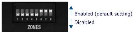
FIG. 18 ZONES Dip Switch
The UP position enables each Zone; the Down position enables each Zone.
Applying Power to the Alero Amplifier
CAUTION: This unit should only have one source of incoming power. Using more than one source of power to the Alero can result in damage to the internal components and a possible burn out.
CAUTION: Apply power to the unit only after installation is complete.
AC Power Plug Connector
The following table provides pinout information for the AC Connector:
| AC Power Plug Connector - Pinout Information | |||||
| PIN Function Description Type | |||||
| 1 Live Mains AC Live Input | |||||
| 2 Neutral Mains AC Neutral Input | |||||
| 3 | P E | P r o t | e | ||
t i v e E a
- Mains Power Fuse - T6.3A H Mains Power Fuse fuse provides over-current protection.
-
Mains Power Switch - The power switch is the AC mains switch, which turns everything off when it is in the Off position, and powers everything on when it is in the On position.
-
Connect a standard IEC 3-pole detachable power cord to the AC Mains power connector on the rear panel.
- Plug the attached power plug into a correctly grounded wall outlet.
- Switch the Mains Power Switch (on the rear panel) to the On position.
Note that the POWER LED on the front panel lights Green to indicate that the amplifier is receiving power (and not in Standby mode).
Entering Standby Mode
To put the Alero Amplifier in Standby Mode:
- Remove signal from the signal sense input, or disable signal sense input. See the Pin 1 - Signal Sense section on page 15 for details.
- Enable 3-5V trigger -> Disable 3-5V trigger
Note that the POWER LED on the front panel lights Red to indicate that the amplifier is receiving power, but is in Standby mode.
Also note that when in Standby mode, the 12V output trigger is turned off.
NetLinx Programming Example: On Signal, OC and Thermal Functions
Overview
The following NetLinx code example illustrates configuring the port (on an NI-3100 NetLinx Central Controller) to properly monitor inputs from the On Signal, OC and Thermal functions:
DEFINE_DEVICE
dvIO = 5001:17:0 // I/O port on an NI-3100
DEFINE_EVENT
DATA_EVENT[dvIO]
{
    ONLINE:
    {
    SEND_COMMAND dvIO,'SET INPUT 1 HIGH' //SENSE ACTIVE HIGH (See Tech Note 777 for wiring instructions)
    SEND_COMMAND dvIO,'SET INPUT 2 LOW' //SENSE ACTIVE LOW (DEFAULT)
    SEND_COMMAND dvIO,'SET INPUT 3 LOW' //AKA "OPEN COLLECTOR"
    }
}
// USAGE EXAMPLE:
BUTTON_EVENT[dvIO,1]
{
    PUSH:
    {
    SEND_STRING 0,'ALR-AMP8 IS ON'
    }
    RELEASE:
    {
    SEND_STRING 0,'ALR-AMP8 IS OFF'
    }
}
BUTTON_EVENT[dvIO,2]
{
    PUSH:
    {
    SEND_STRING 0,'!!!ALR-AMP8 OVERCURRENT!!!
    }
    RELEASE:
    {
    SEND_STRING 0,'ALR-AMP8 OC STATE NORMAL'
    }
}
BUTTON_EVENT[dvIO,3]
{
    PUSH:
    {
    SEND_STRING 0,'!!!ALR-AMP8 THERMAL PROTECTION!!!
    }
    RELEASE:
    {
    SEND_STRING 0,'ALR-AMP8 THERMAL STATE NORMAL'
    }
}
// ALTERNATE USAGE EXAMPLE:
DEFINE_PROGRAM
[dvTP,123] = [dvIO,1] // reflect the state of the amplifier on touch panel button 123
[dvTP,124] = [dvIO,2] // turn the button on when AMP8 is in Over Current Protection
[dvTP,125] = [dvIO,3] // turn the button on when AMP8 is in Thermal shutdown
HARMAN
© 2015 Harman. All rights reserved. Alero, NetLinx, AMX, AV FOR AN IT WORLD, HARMAN, and their respective logos are registered trademarks of HARMAN, Oracle, Java and any other company or brand name referenced may be trademarks/registered trademarks of their respective companies.
AMX does not assume responsibility for errors or omissions. AMX also reserves the right to alter specifications without prior notice at any time.
The AMX Warranty and Return Policy and related documents can be viewed/downloaded at www.amx.com.
3000 RESEARCH DRIVE, RICHARDSON, TX 75082
AMX.com | 800.222.0193 | 469.624.8000 | +1.469.624.7400 | fax 469.624.7153
Last Revised:
9/15/2015

- IMPORTANT SAFETY INSTRUCTIONS
- COPYRIGHT NOTICE
- LIABILITY NOTICE
- AMX WARRANTY AND RETURN POLICY
- ESD WARNING
- FCC AND CANADA EMC COMPLIANCE INFORMATION
- WIRELESS TRANSMITTER COMPLIANCE INFORMATION
- WEEE NOTICE
- CHINA COMPLIANCE INFORMATION
- TABLE OF CONTENTS
- ALERO ALR-AMP-8 8 ZONE POWER AMPLIFIER ....7
- INSTALLATION 10
- NETLINX PROGRAMMING EXAMPLE
- ALERO ALR-AMP-8 8 ZONE POWER AMPLIFIER
- OVERVIEW
- COMMON APPLICATION
- PRODUCT FEATURES
- PRODUCT SPECIFICATIONS
- FRONT PANEL COMPONENTS (LEDS)
- POWER LED (GREEN/RED)
- OC/CLIP LED (YELLOW/RED)
- THERMAL LED (RED)
- REAR PANEL COMPONENTS
- SYSTEM DIAGRAM
- CONTROLLING THE ALERO ALR-AMP-8
- INSTALLATION
- MOUNTING THE ALERO INTO AN EQUIPMENT RACK
- VENTILATION
- RACK MOUNT SAFETY INSTRUCTIONS
- WIRING AND CONNECTIONS
- CONNECTING AUDIO SOURCE DEVICES
- AUDIO (SIGNAL) INPUTS
- SE/BTL (STEREO/BRIDGE MODE) SWITCHES (1-8)
- CONNECTING INPUT DEVICES IN STEREO MODE
- CONNECTING INPUT DEVICES IN BRIDGE MODE
- CONNECTING SPEAKERS
- SPEAKER OUTPUT CONNECTORS
- CONNECTING SPEAKERS IN STEREO MODE
- CONNECTING SPEAKERS IN BRIDGE MODE
- I/O (CONTROL INPUT) PORT
- PIN 1 - SIGNAL SENSE
- EXTERNAL SIGNAL SENSE SWITCH
- PIN 3 - 12V (IN) TRIGGER
- PIN 4 - TRIGGER (LOOP OUT)
- PIN 5 - LOCAL/TRIGGER GND
- PIN 6 - 3-5V LOGIC LEVEL TRIGGER
- 3-5V TRIGGER SWITCH
- PINS 7 & 8 - THERMAL OVERLOAD AND OC (OVERCURRENT) MONITOR INDICATORS
- PIN 9 - ON SIGNAL OUTPUT / 12V TRIGGER
- ON SIGNAL OUTPUT
- 12V TRIGGER
- PIN 10 - STATUS GND
- ON/OFF CONTROL (12V TRIGGER, 3-5V TRIGGER AND SIGNAL SENSE)
- ENABLING AND DISABLING ZONES
- APPLYING POWER TO THE ALERO AMPLIFIER
- AC POWER PLUG CONNECTOR
- ENTERING STANDBY MODE
- NETLINX PROGRAMMING EXAMPLE: ON SIGNAL, OC AND THERMAL FUNCTIONS
Brand : AMX
Model : Alero ALR-AMP
Category : Receiver