
EL-24 - Chlorinator ZODIAC - Free user manual and instructions
Find the device manual for free EL-24 ZODIAC in PDF.

| Product Type | Salt Chlorinator |
| Brand | Zodiac |
| Model | EL-24 |
| IP Rating | IP23 |
| Salt Level Required | 4000 - 6000 ppm (recommended 6000 ppm) |
| Chlorine Output Levels | 8 adjustable levels (1-8) |
| Timer Periods | 2 separate time periods per day |
| Automatic Cell Cleaning | Yes, under normal conditions |
| Pipe Size Compatibility | 40 mm |
| Installation Requirements | Horizontal installation, water connections downward; not within 3.5m of pool; after filter and heater |
| Power Supply | Standard mains (3-pin plug) |
| Pump Current Limit | 8 amps maximum |
| Fault Codes | NO F (No flow), LOS (Low salt) |
| Warranty Registration | Online at www.zodiac.com.au/warranty |
| Maintenance Schedule | Fortnightly checks (cell, water chemistry), 3-monthly (cell connections, insect prevention), 6-monthly (chlorine levels, timer adjustment) |
| Included Accessories | Cell cable, power cord, earth wire, active/neutral wires |
| Cell Type | With negative charge sensor |
| Typical Pool Size | Approximately 50,000 litres |
| Operating Temperature | Up to 40°C |
| Safety Features | Gas trap design, fail-safe sensor, automatic cleaning |
Frequently Asked Questions - EL-24 ZODIAC
User questions about EL-24 ZODIAC
0 question about this device. Answer the ones you know or ask your own.
Ask a new question about this device
Download the instructions for your Chlorinator in PDF format for free! Find your manual EL-24 - ZODIAC and take your electronic device back in hand. On this page are published all the documents necessary for the use of your device. EL-24 by ZODIAC.
USER MANUAL EL-24 ZODIAC
natural_image
Exterior view of a ZODIAC EL-24 saltwater chlorinator device and its transparent internal chamber (no visible text or symbols on the device itself)INDEX
General Overview 3
Chlorinator Control Installation....3
Cell Installation....4
Pool Preparation 5
Programming 5
Chlorine Output 6
User Mode 6
Setting The Right Chlorine output And Filtration Time....7
General Operation/Pool Chemistry 7
Setting the right Chlorine Output and Filtration Time. 7
Chlorinator Maintenance and Troubleshooting 8
Maintenance of Your
Chlorinator....9
Troubleshooting 10
Warranty....11
Congratulations! You have purchased an Zodiac EL-24 Salt Chlorinator. Please read the instructions carefully and your purchase will provide you with years of trouble free use.
Your Zodiac Chlorinator works by converting some of the salt (sodium chloride) in your pool into chlorine which starts to destroy algae and bacteria and sanitises your pool. As part of the process, the chlorine is converted back into salt and hence salt is not consumed.
Your Chlorinator control has many features which ensure simple operation of your chlorinator and Filtration system.
The EL-24 Chlorinator has an internal electronic time clock designed to operate the Filtration pump up to 2 separate time periods each day. The control has a non replaceable backup power source which is designed to maintain timer setting memory in the event of an infrequent and short power interruption.
WARNING: This appliance is not intended for use by persons including young children or infirm persons with reduced physical, sensory or mental capabilities, or lack of experience or knowledge, unless they have been given supervision or instruction concerning use of the appliance by a person responsible for their safety.
Please ensure that young children are supervised to ensure that they do not play with the pump or chlorinator.
To avoid a safety hazard, the supply cord if damaged, must only be replaced by Zodiac, or its service agent or a suitably qualified person.
CHLORINATOR CONTROLLER INSTALLATION
The EL-24 chlorinator controller has a Rating of IP23 enabling it to be installed outdoors.
Regulations require that the control is not allowed to be located within 3.5 metres of the pool water.
The chlorinator controller should be installed in a well ventilated position ideally away from direct sunlight. Ensure that the unit is not located near pool chemicals as fumes may damage the control.
When installing the controller on a post, first attach a flat waterproof panel at least 300mm wide by 500mm long. Make sure the controller is located centrally on the panel and sits flat.
Plug the 3 pin plug into a suitable weatherproof outlet and then plug the pump into the 3 pin socket in the chlorinator controller.
Note: The pump current rating must not exceed 8 amps.
The Chlorinator Cell should be the last piece of equipment installed on the pipe work just prior to the return to the pool. However if valves are installed between the Chlorinator and the pool outlet, it is essential that they cannot deadhead the pump. If the pressure in the cell exceeds 250kPa and/or the water temperature exceeds 40 degrees Celsius, the cell may fail.
WARNING: Never install the cell before the pump or heater
The Cell MUST be installed with the barrel unions underneath (water connections pointing downwards) and the cell should be horizontal. The cell is suitable for 40mm pipe only. Use high pressure PVC pipe and glue into the barrel union tails. Make sure that the 'O-rings are correctly fitted and the unions are tightened firmly.
Direction of flow through the Cell is critical – unit must be plumbed with the water entering the cell at the end closest to the terminal connections
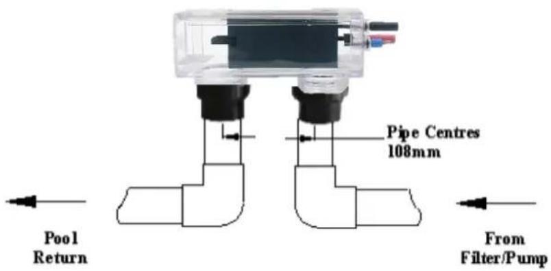
WARNING: It is essential that pipe work and equipment do not allow gases generated from the cell to collect and build up.
WARNING: Cell must be installed horizontally with water connections pointing downwards – this creates a safety gas trap. Installation in any other way may cause explosion, injury or death.
WARNING: Cell must be installed in the return pipework to the pool. Always install after filter, gas heater, and solar heater or heat pump connections.
WARNING: DO NOT install isolation valves on inlet or outlet of cell.
Once the Cell is located, connect the black multi-core cable to the cell. All terminal posts and cell cable connectors are colour coded, ensure the correct colours are connected. Ensure that the connectors are seated firmly and correctly.
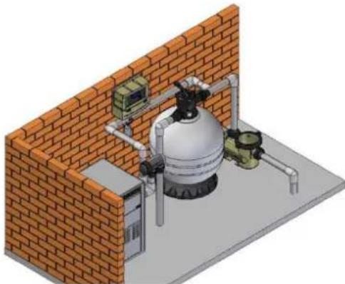
natural_image
Isometric illustration of a gas cylinder mounted on a brick wall, with piping and control panel (no text or symbols)The recommended salt level for the EL-24 Salt Chlorinator is 6,000ppm. The chlorinator requires between 4000ppm and 6000 ppm of salt dissolved into the pool water. The level of salt will depend on water temperature, but if a level of 6000 ppm dissolved salt is allowed for, your chlorinator will always be able to produce the maximum level of chlorine. We recommend you add 6 kgs of salt for every 1000 litres of water (a typical pool of around 50,000 litres requires 300kg of salt).
Salt should always be added at the shallow end of the pool and allowed to dissolve. Running the pump will mix the water and speed the dissolving process.
WARNING: Never add salt to the skimmer box!!
NOTE: Plug the pump directly into a power outlet (bypass the chlorinator) and run for 8-10 hours to ensure the salt is dissolved prior to running the chlorinator.
When the salt is dissolved, connect the pump to the chlorinator and run it on maximum chlorine output. Check that low salt is not indicated on the screen. If it is, check again in 24 hours. If the low salt indicator still persists, have the salt level checked by your local pool shops and ensure it is increased to 6000 ppm.
PROGRAMMING
Setting Current Time/Day
Select Off
(a) Press the MENU button and screen should display CLK. Press ENTER
(b) Press ENTER and the hour digit will flash. Use up and down arrows to adjust.
(c) Press ENTER to change to minutes and set.
(d) Press ENTER and select AM or PM
(e) Press MENU to save
Setting Timers
Your Chlorinator has 2 timers enabling you to set different periods in which your chlorinator/pump will operate. Timers are set by entering a start time and an off time. To set timers, do the following:
(a) Press the MENU button twice and screen should display TMR. Press ENTER
(b) Use up and down arrows to adjust start time for TIMER1. Press ENTER
(c) Use up and down arrows to adjust the off time for TIMER 1. Press ENTER.
(d) Repeat for TIMER 2
Programming Recommendations
Zodiac recommend that you use two timers, one for the morning and one for the evening and typically for periods of 2-5 hours for each (depending on pool size and season). Your chlorinator is most effective if running in the early morning or evening when it is cooler (strong sunlight consumes more chlorine). As a factory default, the control is set to come on at 08:00am and 04:00pm both for periods of 4 hours.
CHLORINE OUTPUT
To adjust the chlorine output:
(a) Use Increase/Decrease arrows for setting the chlorine output level of the chlorinator. The chlorinator output can be set from levels 1 through to 8.
(b) Chlorine Output display shows the level set
The user mode buttons enable you to select and to automatically or manually control the chlorinator/pump. Functions are as follows:
(a) POOL MODE:
Auto - Running The chlorinator/pump will run according to how you have set the timers
Manual -Running The chlorinator/pump will run continuously.
Manual - Stopped The chlorinator/pump will stay off continuously.
Maximum efficiency will be achieved from you chlorinator at the following levels:
Water temperature 15 Degrees – Salt level required is 6000 ppm
Water Temperature 25 Degrees – Salt level required is 4,100 ppm
FAULT CODES
The User Display can indicate the following fault codes;
- NO F – No flow indication
• LOS – Low salt indication
Refer to troubleshooting table at the end of this manual for actions to correct these errors.
SETTING THE RIGHT CHLORINE OUTPUT AND FILTRATION TIME
Your EL-24 Chlorinator must be run every day to ensure that your pool is correctly sanitised. As the sun dissipates chlorine, running times are higher in the summer compared to the winter. Zodiac recommend that you initially run you chlorinator at maximum output for the first few days, then adjust as required.
Summer
You should set your Chlorinator to operate for 8 to 10 hours per day. Ideally, run it for 4-5 hours in the morning (say 8-12pm) and 4-5 hours in the evening (say 6.00-11pm).
In extremely hot weather it may be necessary to extend the running time if you find that the free chlorine level is too low.
To prevent consumption of chlorine by sunlight, try adding Cyanuric Acid as recommended by your local pool professional. Additional benefit will be gained by operating your chlorinator and pump into the evening when the strong sunlight has abated.
Chlorine is most effective when the pH of your pool water is 7.4. The electro-chemical process of the chlorinator, (change salt into chlorine) will automatically raise the pH of your pool water, so it is very important to check your pH weekly and adjust as necessary.
Winter
You should set your Chlorinator to operate for 6 to 8 hours per day. Again, running it in the morning and evening is preferable.
Checking Chlorine Level
Ideally, check your chlorine level after the morning operating period. The free chlorine residual level should be somewhere between 1 and 3 parts per million. Increase or decrease the output of the Chlorinator to get the right residual chlorine level. It may also be necessary to adjust the operating period if you are running at minimum or maximum output.
As previously mentioned, sunlight rapidly dissipates the amount of free chlorine in your pool. Chlorine stabiliser greatly reduces this effect. Without stabiliser, you may need to run your Chlorinator and filtration system up to 16 hours per day or longer. Keep the Stabiliser reading between 30 and 60ppm.
pH Level
You should keep you pH level between 7.0 and 7.4 for fibreglass pools and 7.2 to 7.6 for other pools.
Total Alkalinity
The ideal range is between 80 and 120 ppm.
Salt Level
Although salt is not consumed by the chlorinator, salt is lost during backwashing, and when your pool overflows due to rain or splashing. The correct salt level is important to cell life and the effective operation of your chlorinator. Salt level should be maintained around 6,000ppm but should never be allowed to fall below 4,000ppm.
A typical pool of around 50,000 litres requires 300kg of salt to initially set-up the pool to 6,000ppm. A low salt level warning is indicated on your EL-24 Chlorinator if the salt level drops. If Low Salt is indicated, check again in 24 hours and then if it is still indicated, add two 25kg bags of salt to the shallow end of your pool. Run the filtration system for approx. 6 hours to help mix the salt in the pool. It can take up to a day for the salt to fully dissolve.
If the low salt light is still on, then you should get your pool water tested. If the Salinity is above 6000ppm then you may need to have your Chlorinator checked.
Warning: Never add salt directly to the skimmer box. This practice should be avoided as it allows very high concentrations of salt to be passed through your filtration and other pool equipment.
CHLORINATOR MAINTENANCE AND TROUBLESHOOTING
If the supply cord is damaged, it must be replaced by Zodiac or its service agent or a similarly qualified person in order to avoid a hazard.
Warning: Operating the chlorinator with less than 3000 ppm of dissolved salt in the water may cause damage to the cell and will void the warranty. Never start the chlorinator, until the correct quantity of salt has been added and dissolved in your pool water.
CELL MAINTENANCE
Your EL-24 Chlorinator has an automatic cleaning feature that under normal conditions, will keep the cell plates clear of deposits of salt and calcium.
The cell has a negative charge sensor that monitors the flow and salt levels of the water. This sensor is designed to be fail safe. As it is negative charge deposits of calcium or other debris may be deposited on it and cause it to indicate a low salt or no flow condition. Should a low salt condition be indicated, have your salt level checked at your local pool shop. If the low salt condition persists, or a no flow condition is indicated when the supply pump is operating, you may need to manually clean your chlorinator Cell.
- Close applicable valves
- Disconnect the chlorinator from the mains by removing the 3 pin plug
- Disconnect the cell wires
- Undo the barrel nuts connecting the cell to your filtration system
- Turn the cell upside down (inlet and outlet on top) and fill the cell with a mix of 1 part Hydrochloric acid to 10 parts water and leave standing for a few minutes. As an alternative, you may use an approved commercial Cell cleaning solution
- Repeat if necessary and then rinse well in clean water
- Re-install the cell ensuring o-rings are correctly located and barrel nuts are tightened to prevent leaks
- Re-connect cell wires ensuring all connections are in the proper colour coded connector
- Return all valves to their normal positions, re connect power to the chlorinator and turn on at power point.
WARNING: Follow safety instructions provided with the Hydrochloric acid or cleaning solution. When handling Hydrochloric Acid, the use of eye protection, mask and gloves are highly recommended. Extreme caution should be taken whenever handling Hydrochloric Acid or Cell Cleaning Solution.
Maintenance Schedule: Your new product incorporates moving parts and withstands high velocity water with chemicals in it. Some of these parts will wear in the normal course of use and require regular checks and maintenance. Performing these checks and maintenance will identify parts that have worn and require repair/replacement before further serious damage is sustained. A small amount of regular care and attention to your pool equipment will help ensure long life and trouble free performance.
To protect against extremes of temperature, your unit is vented to allow expensive electronics to cool. Ants and some insects are often attracted to the warmer, dry environment inside the enclosure. We recommend that, with power turned off, you spray a surface insecticide on the surfaces surrounding the control to prevent ant and insect ingress. Repeat every three months or as necessary.
| Timing | Maintenance Check | Service action (if required) |
| Fortnightly | Check cell for calcium build up | Soak electrode in mixture of 10 parts water to 1 part acid. Use a soft brush only if required |
| Check water chemistry | Balance pH in pool and adjust output of unit to ensure satisfactory production of chlorine | |
| Check cable connections to cell | Ensure no water contact is occurring with pins | |
| Three Monthly | Check cell connections for leaks | Isolate Pump, turn power off, clean and grease O rings or replace if necessary |
| Check for insects/ants | Spray a surface insecticide on the surfaces around the unit to prevent ant and insect ingress. | |
| Six Monthly | Check chlorine levels and pump operating hoursPrevent insect ingress to controller | Adjust timer and output depending on demand for current season. Turn controller off, use an insect spray and spray onto walls around controller. Do not spay directly into unit. |
Important note: Regular maintenance is important to ensure long life and trouble free performance of your pool equipment. If unable to perform the maintenance yourself, contact your local Zodiac office who will arrange a trained service technician to perform the maintenance for you.
Your EL-24 Chlorinator has diagnostic and safety features to make it easy to maintain your system. The table below summarises potential faults and their causes.
| Fault Indication | Potential Cause | Remedy |
| No Flow | Pump turned off/disconnected or valves closedBlue wire disconnected from cell | Ensure valves/pump onConnect Blue sense wire to cell |
| Low salt | Salt level in pool has dropped too lowPool water temperature is lowCell has calcifiedCell has failed | Take sample of water to pool shop and check salt level – add salt as recommended.Add salt and turn chlorinator output down until the water is warmerClean cellCall for Service |
| Display blank | No Power to ControllerFuse blown | Plug in controller and ensure mains power availableHave a service technician replace fuse (3 amp slow blow) |
| Low/No chlorine in pool | Cables not connected to cellTimer period too shortChlorine output level too lowFilter needs backwashingPh too highPool stabiliser (cyanuric acid) too lowSalt level too low | Connect cablesIncrease timer period – particularly in summerIncrease chlorine outputBackwash filterBalance pH level to 7.4 – 7.6Increase Stabiliser between 30 and 60 ppmIncrease salt to above 6000 ppm |
| Clock loses time when mains power removed | Battery life expired | Call a technician |
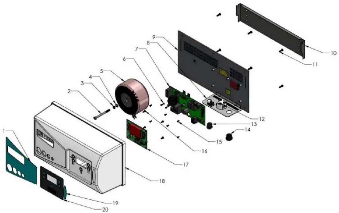
| ITEM No | DESCRIPTION | PART NUMBER | QTY |
| 1 | LABEL-PART OF LABEL575 | LABEK575 | 1 |
| 2 | BOLT | 880901 | 1 |
| 3 | SPRING WASHER | 886900 | 1 |
| 4 | FLAT WASHER | 885900 | 1 |
| 5 | TRANSFORMER | 70304 | 1 |
| 6 | SCREW | 40233 | 8 |
| 7 | POWER PCB | 72501 | 1 |
| 12 | PLUG BASE 3 PIN | 20026 | 1 |
| 9 | BACK PANEL | 1112875 | 1 |
| 10 | WALL MOUNT BRAKET | 1112877 | 1 |
| 11 | SCREW | 40340 | 6 |
| 12 | PLUG BASE 3 PIN | 20026 | 1 |
| 13 | HEYCO CORD GRIP - POWER CORD | 20008 | 1 |
| 14 | HEYCO CORD GRIP- CELL CORD | 20028 | 1 |
| 15 | SCREW | 40340 | 6 |
| 16 | SCREW FOR USER PANEL | 39-52-02 | 4 |
| 17 | USER PCB | 72501 | 1 |
| 18 | COVER | 78946 | 1 |
| 19 | LABEL PART OF LABEL575 | LABEL575 | |
| 20 | LABEL PART OF LABEL575 | LABEL575 | |
| NOT SHOWN | CELL CABLE | 703012 | 1 |
| NOT SHOWN | POWER CORD | 350029 | 1 |
| NOT SHOWN | EARTH WIRE | 703011 | 1 |
| NOT SHOWN | ACTIVE NEUTRAL WIRES | 78771 | 1 |
| NOT SHOWN | LABEL- EARTH | LABEL28 | 1 |
| NOT SHOWN | RIVETS | HSP171 | 2 |
| NOT SHOWN | EARTH TAB | 78750 | 1 |

For full warranty terms and conditions and to register your warranty, simply visit www.zodiac.com.au/warranty and complete your details. Or scan the QR code and be taken directly to the registration page
Record your Equipment details here for quick reference:
Model No.: ____
Serial No.: ____

Zodiac is a registered trademark of Zodiac Group Australia Pty Ltd ABN 87 002 641 965
ZODIAC CUSTOMER SERVICE CENTRE
Zodiac Group Australia 219 Woodpark Rd, Smithfield, NSW. 2164 Australia
Tel; 1300 763 021
Fax; 1300 781 688
Email; Apac.aftersales@zodiac.com
www.zodiac.com.au
Due to constant developments and improvements, specifications may change without notice. Improper use could affect performance and void warranty
©Copyright Zodiac Australia Ltd 2018
INST473
- INDEX
- CHLORINATOR CONTROLLER INSTALLATION
- WARNING: Never install the cell before the pump or heater
- Direction of flow through the Cell is critical – unit must be plumbed with the water entering the cell at the end closest to the terminal connections
- WARNING: Never add salt to the skimmer box!!
- PROGRAMMING
- Setting Current Time/Day
- Setting Timers
- Programming Recommendations
- CHLORINE OUTPUT
- POOL MODE:
- FAULT CODES
- SETTING THE RIGHT CHLORINE OUTPUT AND FILTRATION TIME
- Summer
- Winter
- Checking Chlorine Level
- pH Level
- Total Alkalinity
- Salt Level
- CHLORINATOR MAINTENANCE AND TROUBLESHOOTING
- CELL MAINTENANCE
- ZODIAC CUSTOMER SERVICE CENTRE
Brand : ZODIAC
Model : EL-24
Category : Chlorinator