
VDC-C1575VP - Security Camera SANYO - Free user manual and instructions
Find the device manual for free VDC-C1575VP SANYO in PDF.


| Product Type | Security Camera |
| Brand | Sanyo |
| Model | VDC-C1575VP |
| Image Sensor | 1/3-inch CCD |
| Resolution | 700 TVL (analog) |
| Lens Type | Fixed focal length, 3.6mm |
| Minimum Illumination | 0.01 lux (color), 0 lux with IR |
| IR Distance | Up to 20 meters |
| Video Output | 1 Vp-p composite, 75 ohms |
| Power Supply | 12V DC ±10% |
| Power Consumption | 4W (max) |
| Dimensions (W x H x D) | 80 x 70 x 140 mm |
| Weight | 0.5 kg |
| Mounting Type | Bracket mount (included) |
| Operating Temperature | -10°C to 50°C |
| Weatherproof Rating | IP66 (indoor/outdoor) |
| Sync System | Internal |
| White Balance | ATW / AWB |
| Cleaning Instructions | Clean lens with soft dry cloth; avoid solvents |
| Maintenance | Check connections periodically; clean IR LEDs |
| Safety Precautions | Use only specified power supply; avoid exposure to rain |
| Spare Parts | Replacement brackets, power adapters available |
| Compliance | CE, FCC |
Frequently Asked Questions - VDC-C1575VP SANYO
User questions about VDC-C1575VP SANYO
0 question about this device. Answer the ones you know or ask your own.
Ask a new question about this device
Download the instructions for your Security Camera in PDF format for free! Find your manual VDC-C1575VP - SANYO and take your electronic device back in hand. On this page are published all the documents necessary for the use of your device. VDC-C1575VP by SANYO.
USER MANUAL VDC-C1575VP SANYO
● Before installing and using the camera, please read this manual carefully. Be sure to keep it handy for later reference.
This instruction manual covers the following models. Any difference among the three models is indicated when necessary:
among the union members is indicated when necessary VDC-C1575WR
VDC-D1595VP
VDC-W1595VP
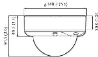
Dimensions: mm (inches)
Depending on the conditions of use, installation and environment, please be sure to make the appropriate settings and adjustments. If you need help with installation and/or settings, please consult your dealer or an Authorized Sanyo Service Center.
Please note:
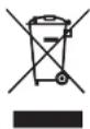
Your SANYO product is designed and manufactured with high quality materials and components which can be recycled and reused.
This symbol means that electrical and electronic equipment, at their end-of-life, should be disposed of separately from your household waste.
Please dispose of this equipment at your local community waste collection/recycling centre. In the European Union there are separate collection systems for used electrical and electronic products.
Please help us to conserve the environment we live in!
This symbol mark and recycle system are applied only to EU countries and not applied to countries in other areas of the world.
TROUBLESHOOTING
Before sending the camera out for repair, check the items below. If the problem persists after checking these items, consult your dealer or an Authorized Sanyo Service Center.
■If no image appears
● Is the coaxial cable attached securely?
● Are the power and voltage normal?
● Has the iris of the lens been adjusted correctly (with the level volume)?
● Is there adequate illumination?
■If the image is unclear
● Is the monitor adjusted correctly?
● Is the lens in focus?
- Is the lens clean?
Dirt or fingerprints on the lens can adversely affect the image. Gently wipe any dirt or fingerprints off the lens with a soft cloth or lens cleaning paper and cleaning fluid (commercially available).
SERVICE
The camera is a precision instrument. Handle it carefully and always follow the safety precautions. If the camera requires service, never try to repair it yourself or open the casing.
For servicing, maintenance, or repairs, consult your dealer or an Authorized Sanyo Service Center.
SPECIFICATIONS
VDC-C1575VP VDC-D1585VP VDC-W1595VP
| Screening system PAI, standard 625 lines, 50 times/sec. | |||
| Image sensor /1/3"roring transfer mode ODD | |||
| Number of effective pixels | 7NZ (H) x 802 (V) | ||
| Hordeable resolution More than 500 TV lines | More than 480 TV lines | ||
| Minimum Humination (approx.) | 1.0 x (F1.4) | 0.65 ix (F1.4, BW mode)1.0 lx (F1.6, case mode) | 1.0 lx (F1.4) |
| Video output 1.0 Vpp=ps/75.5, composite, BNC | |||
| Video SN ratio More than 50 dB (ADC fr) | |||
| Less Bath in walk focal autoatts, 1:2-6.5 mm, F = 1.4:2.0 | |||
| PanTH adjustment Par: ±800, TH ±60P (Calling Installed) | |||
| Darkight compensation | OFF/TON (Senior and monitoring) | ||
| Fis slotting | AVL (CY) off: 98 is available for PC Full-E long) | ||
| White balance | ATW/ATWA | ATW/ATWA | |
| Cam control | ON/OFF | ||
| Wide dynamic range | ON/OFF | ||
| Dynamic range | 54 dB typical | ||
| Sync system DC 12 V low: Internal sys, AC 24 V user Line+lock | |||
| Dark/night function | – | Always active | – |
| Operating environment | Temperature: -10~+50°C (14~122°F) | -10~+40°C (14~184°F) | |
| Humidity loss than 90% RH the condensation | |||
| Power supply | 24 V AC ≤10%, 50 Hz/12 ~15 V DC | ||
| Power consumption (approx.) | 2.6 W | 2.6 W | 4.0 W |
| Weight (approx.) | 850 g (50 Kg) | ||
| Accessories | High-axis search: Large, Medium and Small.....each! | ||
| Rocker cashon.....1 | |||
| Mounting screw.....4 | |||
| Gowel cord.....4 | |||
| Soldering rod.....4 | |||
● The factory setting value is represented in bold.
Appearance and specifications are subject to change without prior notice.
PRECAUTIONS
In case of a problem
Do not use the unit if smoke or a strange odor comes from the unit, or if it seems not to function correctly. Turn off the power immediately and disconnect the power cord, and then consult your dealer or an Authorized Sanyo Service Center.
■Do not open or modify
Do not open the cabinet, as it may be dangerous and cause damage to the unit. For repairs, consult your dealer or an Authorized Sanyo Service Center.
■Do not put objects inside the unit
Make sure that no metal objects or flammable substance get inside the unit. If used with a foreign object inside, it could cause a fire, a short-circuit or damage. Be careful to protect the unit from rain, sea water, etc. If water or liquid gets inside the unit, turn off the power immediately and disconnect the power cord, and then consult your dealer or an Authorized Sanyo Service Center.
■Be careful when handling the unit
To prevent damage, do not drop the unit or subject it to strong shock or vibration.
■Do not install this unit close to magnetic fields The magnetic fields may result in unstable operation.
■Protect from humidity and dust
To prevent damage, do not install the unit where there is greasy smoke or steam, where the humidity may get too high, or where there is a lot of dust.
■Protect from high temperatures
Do not install close to stoves, or other heat sources, such as spotlights, etc., or where it could be subject to direct sunlight, as this could cause deformation, discoloration or other damage. Be careful when installing close to the ceiling, in a kitchen or boiler room, as the temperature may rise to high levels.
■Cleaning
- Dirt can be removed from the cabinet by wiping it with a soft cloth. To remove stains, wipe with a soft cloth moistened with a soft detergent solution and wrung dry, then dry by wiping with a soft cloth.
- Do not use benzine, thinner or other chemical products on the cabinet, as this may cause deformation and paint peeling. Before using a chemical cloth, make sure to read all accompanying instructions. Make sure that no plastic or rubber material comes into contact with the cabinet for a long period of time, as this may cause damage or paint peeling.
■Approvals: IP66
This unit has been certified to IP66 standards when properly installed. Ensure all openings in enclosure are sealed as per manufacturer's instructions.
SANYO
L5BN2/XE, XE2, XE3 (1106KP-CP-a)
SANYO Electric Co., Ltd. Product in Korea
INSTALLATION
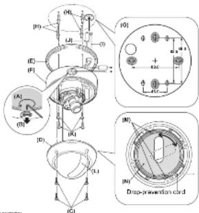

- Since the conduit hole cover is not waterproof-finished, always be sure to seal the cover entirely by caulking, for example, upon completion of installation.
- Make sure to perform waterproofing properly to the ceiling or wall where you are installing the unit.
- When selling up this camera, make sure that it is installed securely. Check that the installation location is strong enough to bear the camera weight before proceeding. Install on a ceiling or wall that has no surface unevenness. In addition, do not touch the camera unit except when settings and adjustments are necessary.
■ When routing the cables on ceiling or wall surfaces: Lassen the conduit hole cover fixing screw (A) on the back of the camera unit base with the hexagonal wrench (medium), open the cover (B), and pass the connection cables through the conduit hole.
1 Loosen the four fixing screws (C) using the supplied hexagonal wrench (large) and remove the dome cover (D).
2 Make screw holes and a cable hole in the rubber cushion (E).
3 Attach the rubber cushion to the back of the camera unit (F).
4 Place the supplied "Mounting template" (G) on the mounting surface, and mark four positions shown in (G).
5 Drill holes at the positions as marked and insert the supplied screw holds (H) in the holes.
6 Cut a hole in the ceiling or the wall for routing the cables.
7 Pass the power cable (I) and video cable (J) from the camera unit through the cable hole in the ceiling or the wall.
8 Align the unit mounting holes of the camera unit with the holes in the ceiling or the wall.
9 Secure with the supplied mounting screws (K).
10 Carry out the settings and adjustments for the camera. Refer to "CONNECTIONS AND SETTINGS" for camera settings and lens adjustments.
11 If a whole surface of the lens does not show through the camera window (L), loosen the screws (M) and adjust the dome liner (N). And then secure the dome cover by tightening the fixing screws (C) with the hexagonal wrench (large).
CONNECTIONS AND SETTINGS
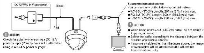
■ CONNECTIONS
■ LENS ADJUSTMENTS
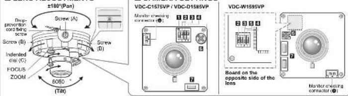
■ CHECKING THE CAMERA IMAGE
You can use the monitor checking cable (sold separately) to display an image on a monitor when setting up the camera to check the surveillance angle and range, lens focus, etc.
Connect the connector of the monitor checking cable to the monitor checking connector (③) on the circuit board and connect the jack of the monitor checking cable to the monitor.
■ LENS ADJUSTMENTS
Once the camera has been installed, adjust the lens section.
CAUTION
- Be careful not to touch the lens section when changing the angle of the camera.
- When loosening the drop-prevention cord fixing screw, be careful not to loosen it too much; otherwise the dome cover may drop.
- Loosen the drop-prevention cord fixing screw, then adjust the pan position (±100°) and the tilt position (±60°).
- Loosen the screw (A) with a Phillips head screwdriver before adjusting the tilt position.
2Loosen the zoom lever screw, turn the zoom lever to the right left to determine the zoom position while viewing the camera images on the monitor, and then re-tighten the screw.
3Loosen the focus lever screw, turn the focus lever to the right/ left to determine the focus position while viewing the camera images on the monitor, and then re-tighten the screw.
4 Tighten the drop-prevention cord fixing screw.
NOTE on Image direction (Wall Installed):
If the monitor image is misaligned, follow the steps below to adjust. ① Loose the screws (B) with the supplied hexagon wrench (small). ② Turn the indented disk (C) to adjust the image direction. ③ Tighten the screws (B) after adjustments are finished.
■ DAY/NIGHT FUNCTION (VDC-D1585VP)
When connected to power, the VDC-D1585VP turns on the DAY/NIGHT function for continuous operation.
THE DAY/NIGHT function automatically switches over between color and black-and-white mode depending on the ambient brightness; for example, choosing color mode during daytime, and black-and-white mode for nighttime monitoring with its increased sensitivity in a darker environment.
NOTE:
This function is disabled if it is set to "Down".
■ CAMERA SETTINGS
The camera comes from the factory pre-adjusted and ready to install, but you can make adjustments or settings if you need. If you have trouble adjusting the camera, consult your dealer or an Authorized Sanyo Service Center.
1 Backlight compensation setting
(VDC-C1575VP, VDC-D1585VP)
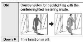
NOTE:
- This function is disabled if ② is set to 'Down'. - If backlight compensation is not corrected in the VDC-C1575VP and VDC-D1585VP when ① is set to "ON", you can correct by adjusting level volume ⑥.
2Iris setting
| ON ♦ | AI: Normal setting (Auto iris) |
| Down | EI: Electronic iris |
NOTE:
This factory preset is optimal, so it is not necessary to change the setting.
3 White balance setting
VDC-C1575VP, VDC-D1565VP
| ON | ATW-A (Auto-tracing white balance - All): Automatic setting for white balance, covering wider range of color temperature than with 'ATW'.• May result in an excessively and unnaturally effected image, depending on the conditions. |
| Down ◆ | ATW (Auto-tracing white balance): Automatic setting for white balance. |
VDC-W1595VP
| ON♦ | ATW-A (Auto-tracing white balance - All): Automatic setting for white balance, covering wider range of color temperature than with "ATW".• May result in an excessively and unnaturally effected image, depending on the conditions. |
| Down | ATW (Auto-tracing white balance): Automatic setting for white balance. |
4 Auto Gain Control (AGC) setting
For adjusting the sensitivity of the camera. Use this setting for shooting in dark environments.
| ON ♦ | Normal setting |
| Down | Set this when there is excessive noise (AGC off) |
5 Wide dynamic range setting (VDC-W1595VP)
Correction is made for simultaneous monitoring of subjects which are different in brightness, one in a dark room and another in bright outdoor environment, for example.
| ON ♦ | When monitoring of subjects which differ in brightness. |
| Down | This function is off. |
6Level volume
If the entire image is too dark or bright, or the backlight compensation is not correct even after 1 is set to "ON", you need to adjust the level volume.
| Counterclockwise (High) | Opens the lens iris, making the entire image brighter |
| Clockwise (Low) | Closes the lens iris, making the entire image darker |
7 Adjusting synchronization error
(AC 24 V users only)
Vertical sync disturbance may occur when a selector is used to switch between multiple cameras connected to one monitor. To prevent vertical sync disturbance, adjust 7.
| VDC-C1575VP. VDC-D1585VP | Press the button to eliminate sync disturbances when needed. |
| VDC-W1595VP | Press each button to eliminate sync disturbances when needed |

CAUTION
When using the DC 12V adaptor, sync setting is set to internal sync.

- TROUBLESHOOTING
- SERVICE
- SPECIFICATIONS
- PRECAUTIONS
- SANYO
- INSTALLATION
- CONNECTIONS AND SETTINGS
- ■ CHECKING THE CAMERA IMAGE
- ■ LENS ADJUSTMENTS
- CAUTION
- NOTE on Image direction (Wall Installed):
- ■ DAY/NIGHT FUNCTION (VDC-D1585VP)
- NOTE:
- ■ CAMERA SETTINGS
- Backlight compensation setting
- White balance setting
- Auto Gain Control (AGC) setting
- Wide dynamic range setting (VDC-W1595VP)
- 6Level volume
- Adjusting synchronization error
- (AC 24 V users only)
Brand : SANYO
Model : VDC-C1575VP
Category : Security Camera