MULTI V PUCKA0 - Water pump LG - Free user manual and instructions
Find the device manual for free MULTI V PUCKA0 LG in PDF.

| Product Type | Condensate Water Pump |
| Brand | LG |
| Model | MULTI V PUCKA0 |
| Application | HVAC condensate removal for air conditioning systems |
| Power Supply | 220-240 V ~ 50/60 Hz |
| Rated Power Consumption | 15 W |
| Maximum Flow Rate | 5 L/h |
| Maximum Suction Lift | 2 m |
| Maximum Discharge Head | 10 m |
| Tank Capacity | 0.5 L |
| Dimensions (W x H x D) | 150 x 120 x 80 mm |
| Weight | 0.8 kg |
| Noise Level | < 30 dB(A) |
| Protection Class | IPX4 |
| Safety Features | Overflow protection, automatic shut-off, thermal overload protection |
| Maintenance | Clean tank and check valve monthly; replace filter annually |
| Spare Parts Available | Replacement pump head, float switch, check valve, filter |
| Warranty | 2 years |
Frequently Asked Questions - MULTI V PUCKA0 LG
User questions about MULTI V PUCKA0 LG
0 question about this device. Answer the ones you know or ask your own.
Ask a new question about this device
Download the instructions for your Water pump in PDF format for free! Find your manual MULTI V PUCKA0 - LG and take your electronic device back in hand. On this page are published all the documents necessary for the use of your device. MULTI V PUCKA0 by LG.
USER MANUAL MULTI V PUCKA0 LG
Please read this installation manual completely before installing the product. Installation work must be performed in accordance with the national wiring standards by authorized personnel only.
Please retain this installation manual for future reference after reading it thoroughly.
Applied(AHU)
Comm.kit
AHU Control Kit Installation Manual
TABLE OF CONTENTS
■ Safety Precautions....3
■ Installation Scene....4
■ Supplies....5
■ Optional Accessories ....5
■ Part Description......6
■ Before Installation ....7
■ Control Kit Installation....9
Mechanical installation....9
Electric wiring work 10-12
Dip switch setting ....12
Dry contact connection_optional accessory....13
■ Thermistors Installation....14
Pipe thermistors installation....14-16
Room thermistor....17
■ Test Operation....18
■ Troubleshooting ....19
Safety Precautions
To prevent injury to the user or other people and property damage, the following instructions must be followed.
■ Incorrect operation due to ignoring instruction will cause harm or damage. The seriousness is classified by the following indications.

WARNING
This symbol indicates the possibility of death or serious injury.

CAUTION
This symbol indicates the possibility of injury or damage.
■ Meanings of symbols used in this manual are as shown below.


Be sure not to do.
Be sure to follow the instruction.

WARNING
■ Installation
Don't touch with the hands while the power is on
- There is risk of fire or electric shock.
Use standard parts(connector).
- Do not disassemble or repair the product. There is risk of fire or electric shock.
For electrical work, contact the dealer, seller, a qualified electrician, or an Authorized Service Center.
- Do not disassemble or repair the product. There is risk of fire or electric shock.
Use the correctly rated breaker or fuse.
- There is risk of fire or electric shock.
Do not install, remove, or re-install the unit by yourself (customer).
- There is risk of fire, electric shock, explosion, or injury.
For installation, always contact the dealer or an Authorized Service Center.
- There is risk of fire, electric shock, explosion, or injury.
Operation
When the product is soaked (flooded or submerged), contact an Authorized Service Center.
- There is risk of fire or electric shock.
Be cautious that water could not enter the product.
- There is risk of fire, electric shock, or product damage.
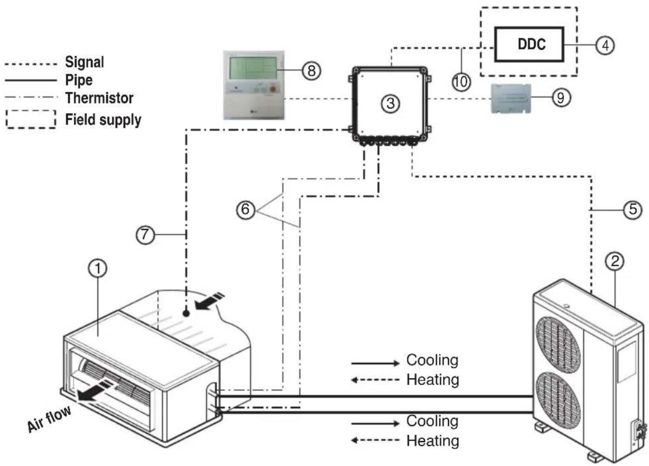
Installation Scene
flowchart
graph TD
    A["Air flow"] --> B["Sensor ①"]
    B --> C["Cooling"]
    B --> D["Heating"]
    C --> E["DDC"]
    D --> E
    E --> F["Field supply"]
    G["Signal"] -.-> B
    H["Pipe"] -.-> B
    I["Thermistor"] -.-> B
    J["Field supply"] -.-> B
    K["Sensor ②"] -.-> E
    L["Sensor ③"] -.-> E
    M["Sensor ④"] -.-> E
    N["Sensor ⑤"] -.-> E
    O["Sensor ⑥"] -.-> B
    P["Sensor ⑦"] -.-> B
    Q["Sensor ⑧"] -.-> B
    R["Sensor ⑨"] -.-> E
    S["Sensor ⑩"] -.-> E
    T["Sensor ⑪"] -.-> E
    U["Sensor ⑫"] -.-> E
Parts and components
| No. Name Remarks | ||
| 1 | Air Handling Unit | Field supply |
| 2 | Outdoor Unit | Universal |
| 3 | AHU Control Kit(PUCKA0) | - |
| 4 | DDC | Field supply(Central control Device) |
Wiring connections
| 5 | Control kit wiring | (Power supply and communication between control kit and outdoor unit) |
| 6 | Pipe thermistors | Evaporator (In/Out) control of Air Handling Unit |
| 7 | Room thermistor | Return air control |
| 8 | Remote controller(PQRCUSA0/1) | Optional accessory |
| 9 | Dry contact (PQDSBC) | Optional accessory |
| 10 | Signal | Fan signal(Low / Middle / High)Defrost / Heating / Cooling signalThemal On/Off |
Supplies
PUCKAO
| Components | AHU Control Kit Room thermistor Pipe thermistors Installation manual | Capacity setting option PCB | Panel(Dry contact support) | |||
| Shape | 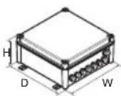 | 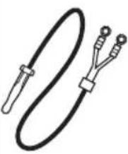 | 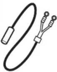 |  | 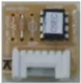 | 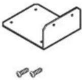 |
| Quantity(EA) | 1 1 2(Pipe In/Out) 1 10(Each 1) | 1(Panel)2(Screw) | ||||
Optional Accessories
Accessories
| Components | Remote controller Dry contact | |
| Model name | PQRCUSA0/1 PQDSBC | |
| Shape | 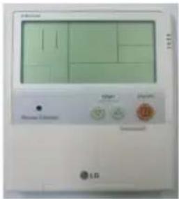 |  |
* For further details of the accessories, refer to the manual provided at the time of purchasing the accessories.
Part Description
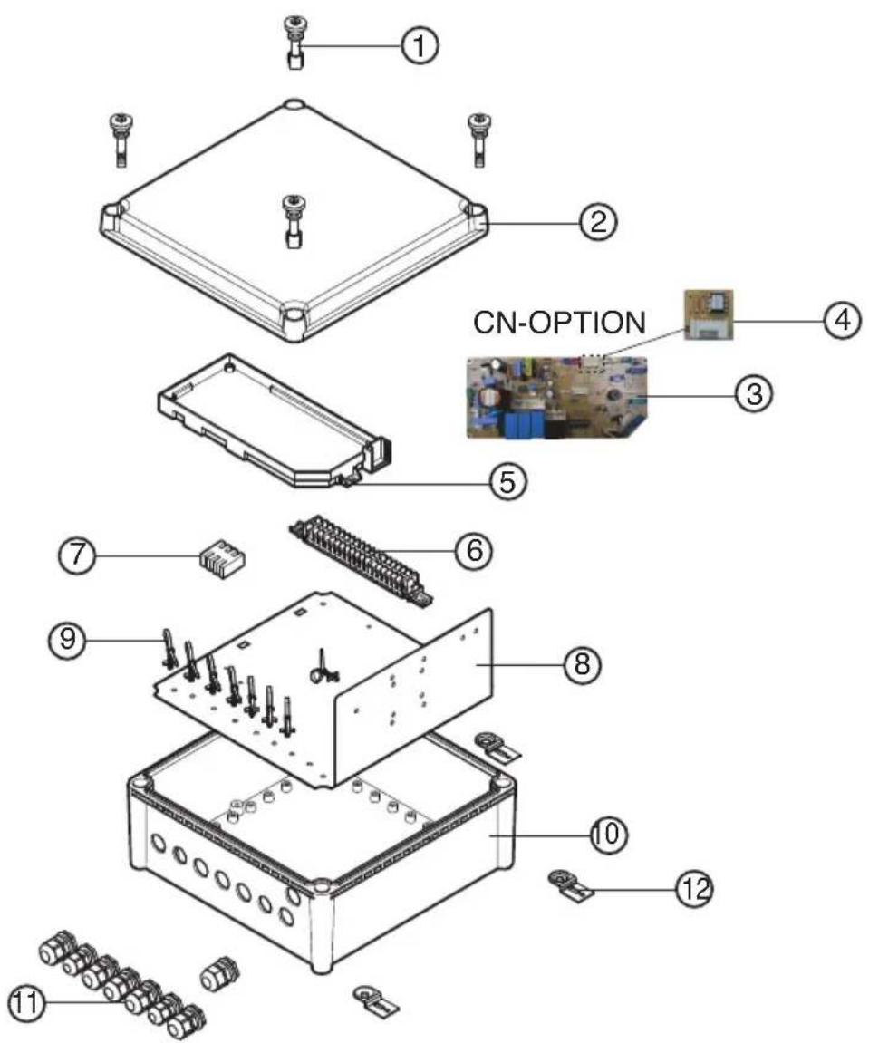
| No. Part Name Quantity(EA) | ||
| 1 | Plastic (+) bolt | 4 |
| 2 | Control box cover | 1 |
| 3 | Main PCB | 1 |
| 4 | Option PCB(24k) | 1 |
| 5 | Main PCB case | 1 |
| 6 | Terminal block (communication) | 1 |
| 7 | Terminal block (POWER Supply) | 1 |
| 8 | Panel | 1 |
| 9 | Support Tie wrap | 8 |
| 10 | Control box case | 1 |
| 11 | Cable gland(2type) | 8 |
| 12 | Bracket | 4 |
Before Installation

CAUTION
■ Don't install or operate the unit in rooms mentioned below.
① Where mineral oil, like cutting oil is present.
② Where the air contains high levels of salt such as air near the ocean.
③ Where sulphurous gas is present such as that in areas of hot spring.
④ In vehicles or vessels.
⑤ Where voltage fluctuates a lot such as that in factories.
⑥ Where high concentration of vapor spray are present.
⑦ Where machines generating electromagnetic waves are present.
⑧ Where acidic or alkaline vapor is present.
⑨ The option boxes must be installed with entrances downward.
⑩ If you want to install the product outdoors, it should be installed with outdoor casing.
■ Check the mentioned below, when you apply the AHU(Field supply).
① If the AHU (Field supply) provided in the field is exclusively for heating, you must not change the operating mode to cooling on the remote controller. If not, it can cause electric shock, injury or death. If you want to operate in cooling mode, AHU (Field supply) must comply with the following details. (Following)
- The insulation level of AHU (Field supply) motor must be 'F' or above, and the protection level must satisfy 'IP 54'.
- AHU (Field supply) must have the drain pan installed.
② For refrigerant piping of outdoor unit, refer to the installation manual supplied with the outdoor unit.
③ For installation of the wired remote controller(PQRCUSA0/1), refer to the manual supplied with the wired remote controller.
④ For connection of the Dry contact (PQDSBC), refer to the manual supplied with the Dry contact (PQDSBC).
■ AHU Control Kit
① Thermistor cable and remote controller wire should be located at least 50mm away from power supply wires and from wires to the controller. Not following this guideline may result in malfunction due to electrical noise.
② Use only specified wires, and tightly connect wires to the terminals. Keep wiring in neat order so that it does not obstruct other equipment. Incomplete connections could result in overheating, and in worse case electric shock or fire.

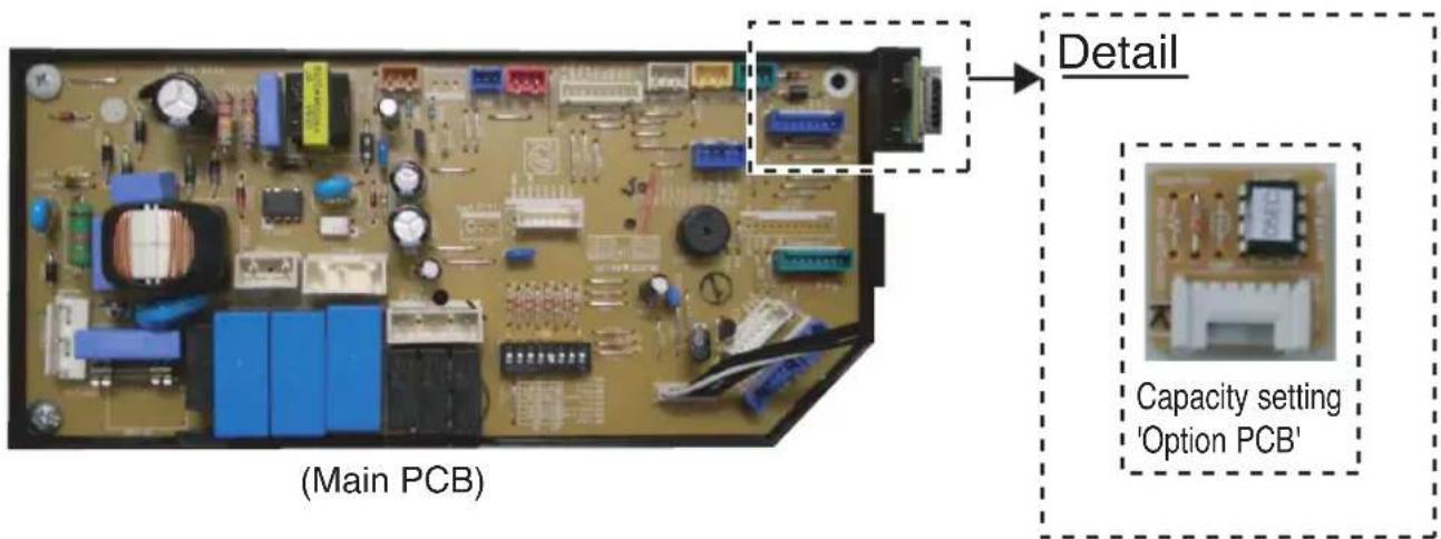
CAUTION
Selection of Evaporator(Air Handling Unit)
See table below for applicable units
Selecting the capacity setting 'Option PCB'(Accessory) according to the capacity mentioned below.
- The corresponding capacity setting 'Option PCB' needs to be selected depending on the need capacity.
- After checking the need capacity, remove the 24k Option PCB equipped in the main PCB, and set up the Option PCB fitted the need capacity in the main PCB.
| Option PCB P/NO | Capacity (Btu/h) | Standard heat exchanger volume ( 10^3 × m^3 ) | Maximum heat exchanger capacity (kW) | Air Flow rate (CMM) |
| EBR65102901 12 | k 2.2 3.5 9~10 | |||
| EBR65102902 18 | k 2.4 5.0 13~1 | 6.5 | ||
| EBR65102903 24 | k 2.6 7.1 14~1 | 8 | ||
| EBR65102904 30 | k 2.9 8.0 20~2 | 6.5 | ||
| EBR65102905 36 | k 3.1 10.0 26.5~32 | |||
| EBR65102906 42 | k 3.4 12.5 28~ | 36 | ||
| EBR65102907 48 | k 4.0 14.0 30~ | 40 | ||
| EBR65102908 60 | k 4.7 15.0 40~ | 50 | ||
| EBR52358920 70 | k 5.2 20.0 60~ | 70 | ||
| EBR52358921 85 | k 5.9 23.0 64~ | 80 |
Saturated Suction Temperature (SST) = 6°C, SH (Superheat) = 5K, Air Temperature = 27°C DB / 19°C WB.
Control Kit Installation
Mechanical installation
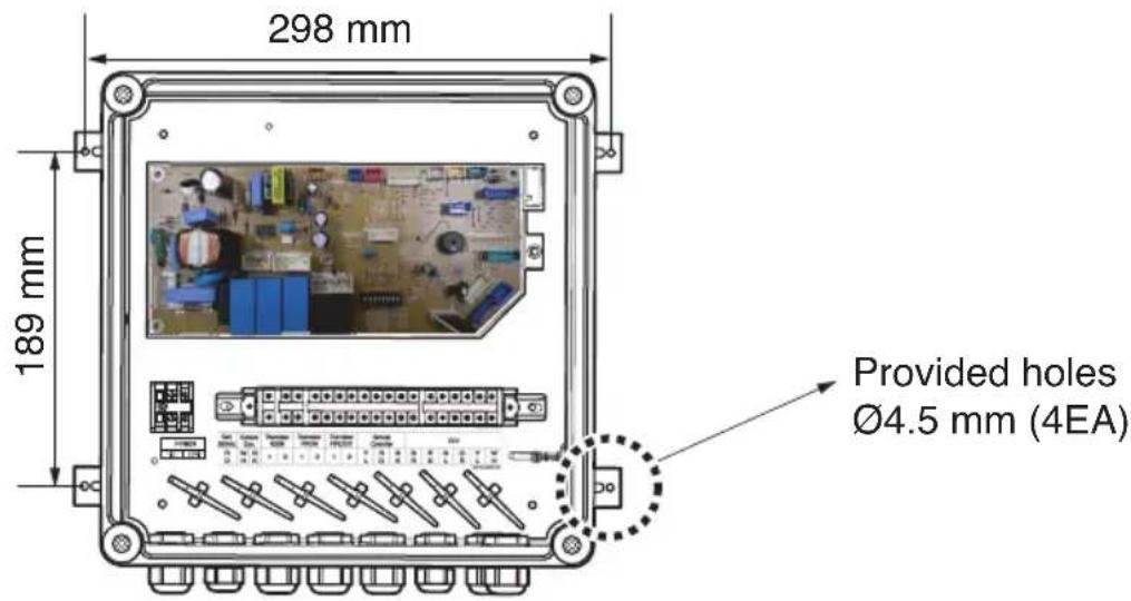
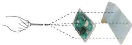
- Remove the Control Kit box cover by unscrewing the plastic (+) bolt(4EA).
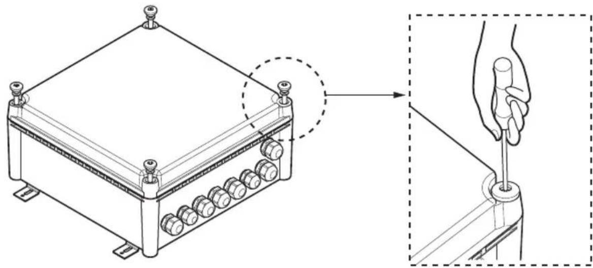
natural_image
Technical line drawing of a mechanical device with a hand holding a screwdriver inserted into a housing (no text or symbols present)- Drill 4 holes on correct position and fix the Control Kit box securely with 4 screws(Field supply) through the provided holes ∅4.5 mm(Reference the length of the holes ∅4.5)
Electric Wiring Work
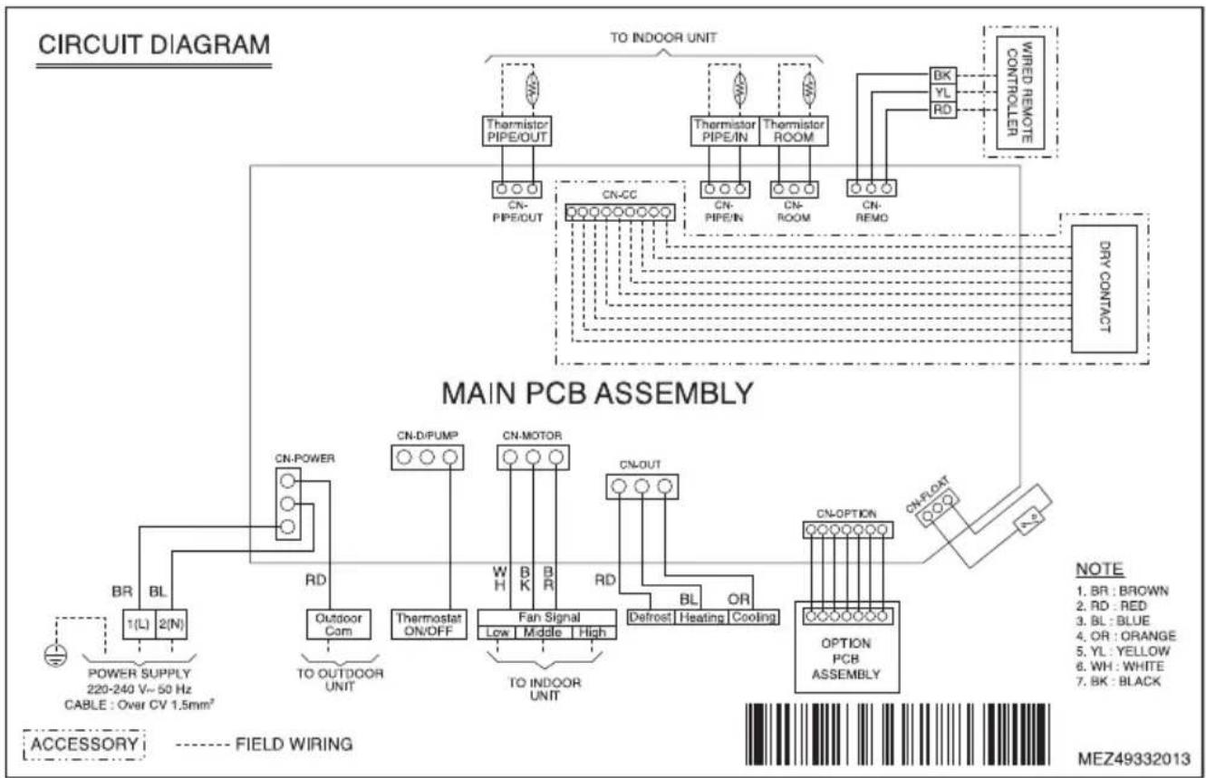
■ Circuit diagram
- For electric wiring, refer to figure 'Circuit diagram' mentioned below.
flowchart
graph TD
    A["TO INDOOR UNIT"] --> B["Thermistor PIPE/OUT"]
    A --> C["Thermistor PIPE/IN"]
    A --> D["Thermistor ROOM"]
    B --> E["CN-PIPE/OUT"]
    C --> F["CN-CC"]
    D --> G["CN-PIPE/IN"]
    D --> H["CN-ROOM"]
    D --> I["CN-REMO"]
    J["WIRED REMOTE CONTROLLER"] --> K["BK"]
    J --> L["YL"]
    J --> M["RD"]
    K --> N["DRY CONTACT"]
    L --> N
    M --> N
    N --> O["MAIN PCB ASSEMBLY"]
    O --> P["CN-Power"]
    O --> Q["CN-D/PUMP"]
    O --> R["CN-MOTOR"]
    O --> S["CN-OUT"]
    P --> T["Outdoor Com"]
    Q --> U["Thermostat ON/OFF"]
    R --> V["Fan Signal Low Middle High"]
    S --> W["Defrost Heating Cooling"]
    T --> X["OPTION PCB ASSEMBLY"]
    U --> X
    V --> X
    W --> X
    X --> Y["CN-OPTION"]
    Y --> Z["NOTE: 1. BR : BROWN, 2. RD : RED, 3. BL : BLUE, 4. OR : ORANGE, 5. YL : YELLOW, 6. WH : WHITE, 7. BK : BLACK"]
    X --> AA["FIELD WIRING: POWER SUPPLY 220-240 V~50 Hz CABLE : Over CV 1.5mm²"]
    AB["ACCESSORY"] --> AC["FIELD WIRING: BR BL 1(L) 2(N)"]
| CONNECTOR NUMBER | LOCATION POINT | FUNCTION |
| CN-POWER AC | POWER SUPPLY | AC POWER LINE INPUT FOR INDOOR CONTROLLER |
| CN-D/PUMP FIELD | WIRING THERMOSTAT ON/OFF SIGNAL | |
| CN-MOTOR FAN | MOTOR CONTROLLER FAN | SPEED CONTROLL OUTPUT |
| CN-OUT FIELD | WIRING | DEFROST, HEATING, COOLING SIGNAL OUTPUT |
| CN-OPTION OPTION | PCB | COMMUNICATION BETWEEN MAIN AND OPTION |
| CN-FLOAT FLOAT | SWITCH INPUT FLOAT SWITCH | SENSING |
| CN-REMO REMOTE | CONTROLLER REMOTE | CONTROL LINE |
| CN-ROOM ROOM | SENSOR ROOM AIR THERMISTOR | |
| CN-PIPE/IN SUCTION | PIPE SENSOR PIPE IN THERMISTOR | |
| CN-CC | DRY CONTACT | DRY CONTACT LINE |
| CN-PIPE/OUT | DISCHARGE PIPE SENSOR | PIPE OUT THERMISTOR |
Electric Wiring Work
■ Connection of the wires
- For connection to outdoor unit and to controller (Field supply):
Pull the wires inside through the cable gland and close that's nut firmly in order to ensure a good pull relieve and water protection.
- The wires require an additional pull-relief. Strap the wire with the support tie wrap.
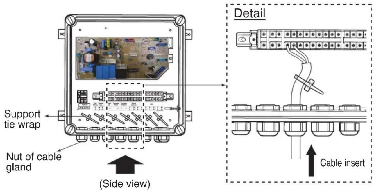
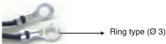
- For the wired remote controller wire and outdoor unit communication wire, remove the coating at the end of the wire to connect and use the ring type ( 3 ) to connect to the terminal block.
- Each wire have to pass the number of the cable gland mentioned below.
| No. Electric wire | |
| 1 | Power supply |
| 2 | Outdoor com. |
| 3 | Thermal Signal(On/Off) |
| 4 | Fan signal(Low / Middle / High) |
| 5 | Defrost / Heating / Cooling signal |
| 6 | Room / Pipe thermistor(In/Out) |
| 7 | Remote controller |
| 8 | DRY contact |
Electric Wiring Work
CAUTION
■ All field supplied parts and materials and electric works must be conform to local codes.
■ Use copper wire only.
■ All wiring must be performed by an authorized electrician.
A main switch or other means for disconnection, having a contact separation in all poles, must be incorporated in the fixed wiring in accordance with relevant local and national legislation.
■ Refer to the installation manual attached to the outdoor unit for the size of power supply electric wire connected to the outdoor unit, the capacity of the circuit breaker and switch, wiring and wiring instructions.
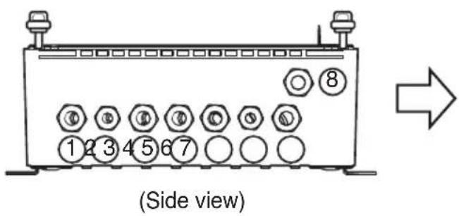
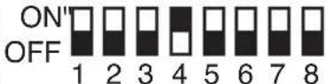
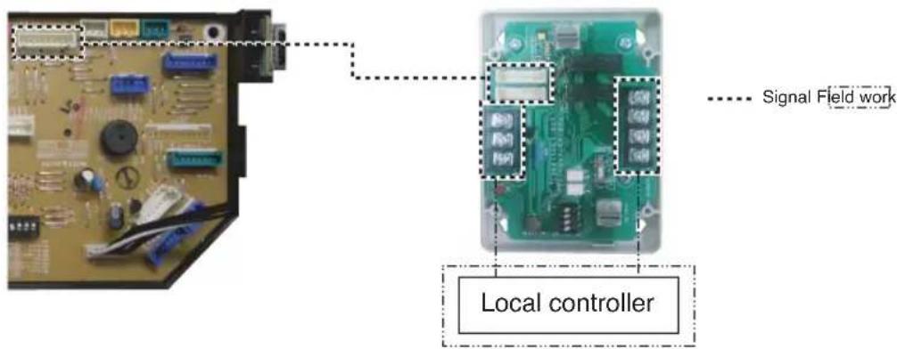
Dip switch setting
If you want to run the Fan(L/M/H) in Heating Mode - defrosting condition, you should set the dip switch 4 to "On" (As shown below)
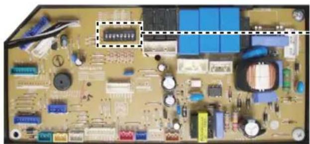
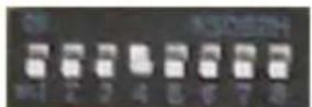
natural_image
Close-up of an electronic circuit board with various components and traces (no readable text or symbols)(Main PCB)
Detail
■ PCB output signal(According to the dip switch 4 setting)
| Output Signal | |||||
| Condition | Thermal On/Off | Fan L/M/H Defrost | Heating Mode | ||
| Dip switch Off | Off Off Off Off | Off | |||
| Cooling Mode Off or On On Off Off | |||||
| Fan Mode Off On Off Off | |||||
| Heating Mode Off or On Off or On Off On | |||||
| Heating Mode - Preheating | On Off Off | On | |||
| Heating Mode - Defrosting | On Off On | On | |||
| Auto Mode The Same as Cooling or Heating Mode | |||||
| Off Off Off Off Off | |||||
| Dip switch On | Cooling Mode Off or On On Off Off | ||||
| Fan Mode Off On Off Off | |||||
| Heating Mode Off or On On Off On | |||||
| Heating Mode - Preheating | On On Off | On | |||
| Heating Mode - Defrosting | On On On | On | |||
| Auto Mode The Same as Cooling or Heating Mode | |||||
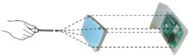
Dry contact connection\_optional accessory
- Using screw(4EA), fix the dry contact on the bracket.
natural_image
Hand holding a tool interacting with a green circuit board and a transparent rectangular component (no text or symbols visible)* Applicable dry contact model - PQDSBC
- Using cable, connect the dry contact to main PCB. For more information, please refer to dry contact installation manual.
- Using screw(4EA), fix the dry contact upper cover to bottom cover.
natural_image
Diagram showing a hand holding a tool interacting with two connected components: one with a blue diamond shape, the other with a green circuit board (no text or symbols present)- Combine the dry contact upper cover to bottom cover with screw(2EA).
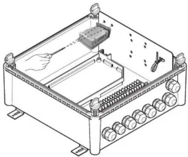
natural_image
Technical line drawing of an electrical enclosure with internal components and wiring (no text or symbols)Thermistors Installation
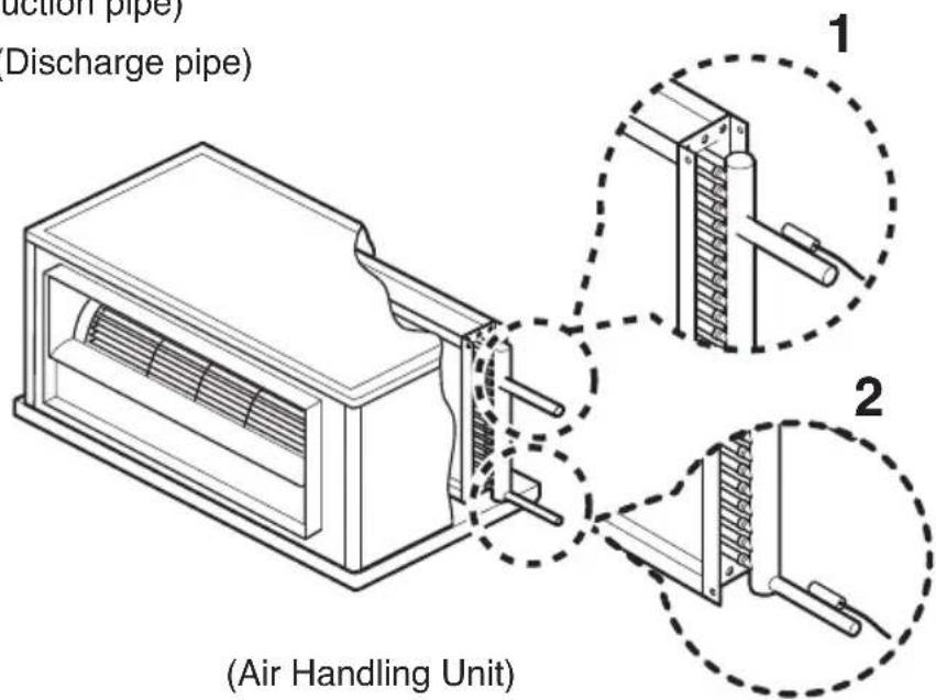
Pipe thermistors Installation
Location of the pipe thermistors
A correct installation of the thermistors is required to ensure a good operation :
- Pipe_In
: Install the thermistor behind the distributor on the coldest pass the heat exchanger (contact your heat exchanger dealer).
- Pipe_Out
: Install the thermistor at the outlet of the heat exchanger as close as possible to the heat exchanger.
Evaluation must be done to check if the evaporator is protected against freeze-up.
Execute test operation and check for freeze-up.
1 Pipe_In(Suction pipe)
2 Pipe_Out(Discharge pipe)
Pipe thermistors Installation
Installation of the pipe thermistor cable
-
Put the thermistor cable in a separate protective tube.
-
Always add a pull-relief to the thermistor cable to avoid atrain on the thermistor cable and loosening of the thermistor. Strain on the thermistor cable or loosening of the thermistor may result in bad contact and incorrect temperature measurement.
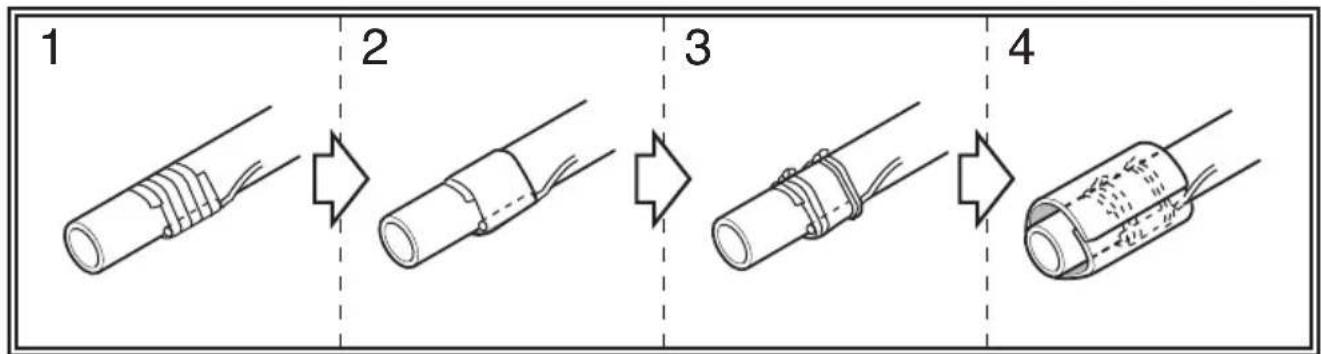
Fixation of the pipe thermistors (Field work)
- Fix the thermistor with insulating aluminum tape (Field supply) in order to ensure a good heat transference.
- Put the supplied piece of rubber around the thermistor in order to avoid loosening of the thermistor after some years.
- Fasten the thermistor with 2 tie wraps.
- Insulate the thermistor with the supplied insulation sheet.
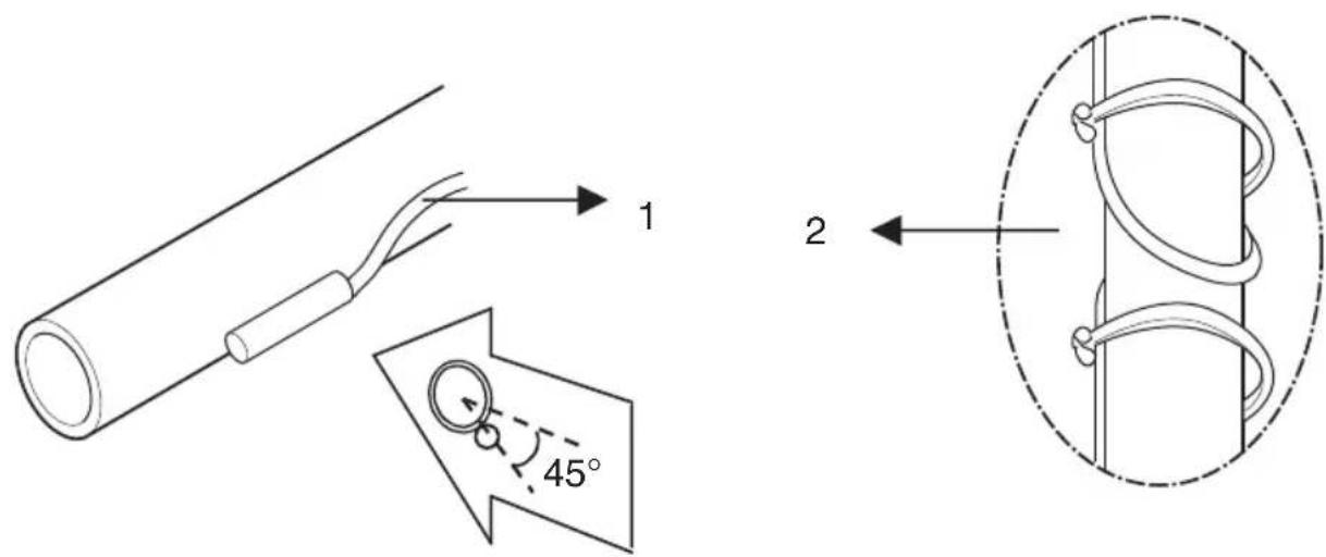
Pipe thermistors Installation

INSTRUCTION
- Put the thermistor wire slightly top to avoid water accumulation on down of the thermistor.
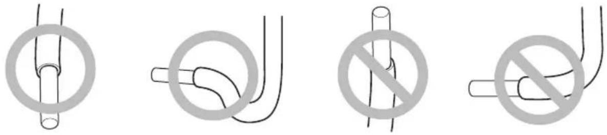
■ Make good between thermistor and evaporator. Put the top of the thermistors on the evaporator, this is the most sensitive point of the thermistor.
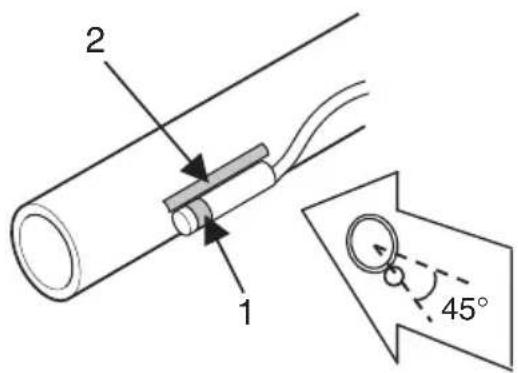
1 Most sensitive point of the thermistor
2 Maximize the contact
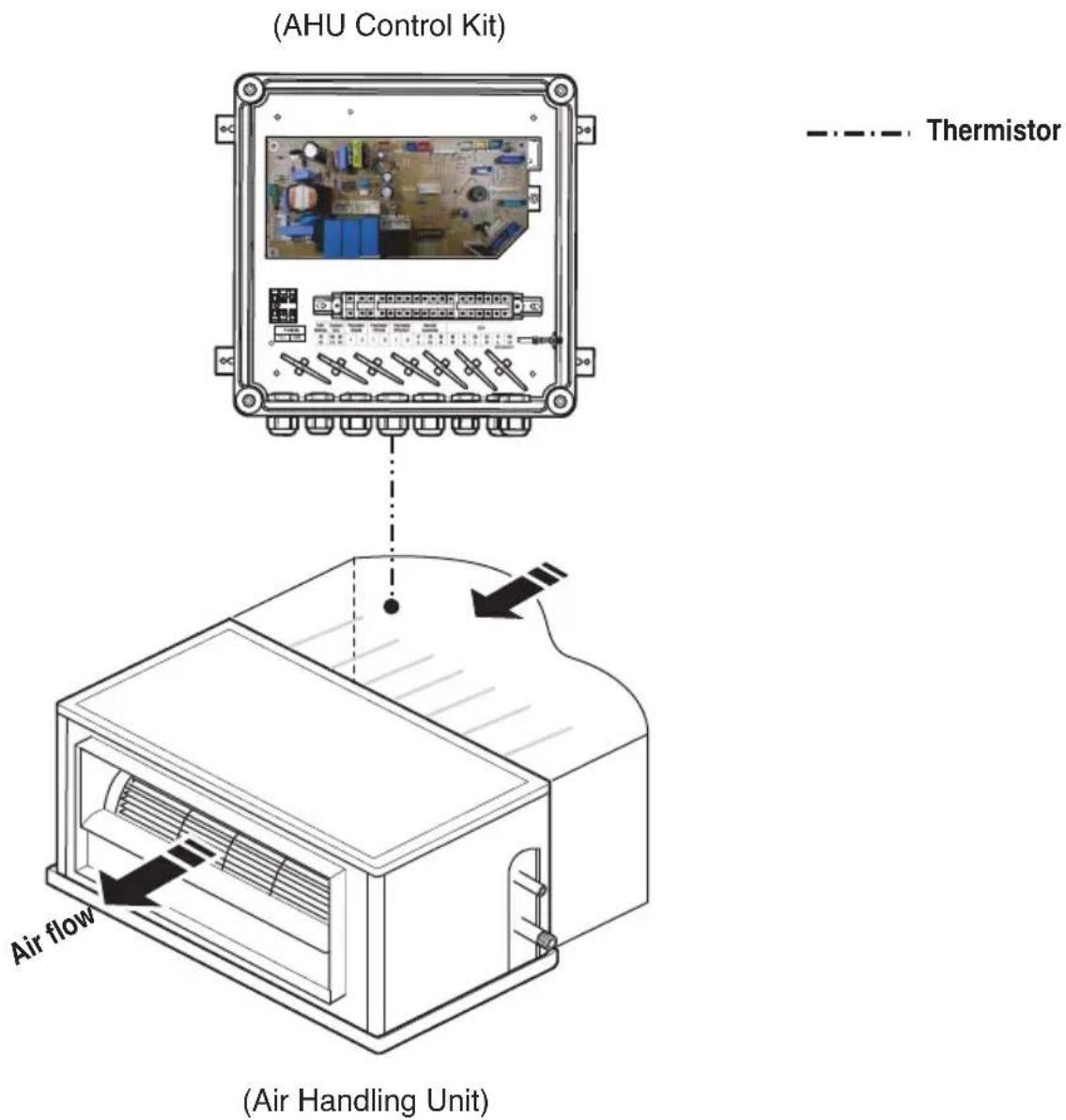
Room thermistor
Installation of the Room thermistor
- The room thermistor have to be installed in the return air part of the AHU(Field supply) mentioned below.
Test Operation
Before test operation, be sure all information is understood completely, and follow the guideline of manual.
■ Check the refrigerant piping of outdoor unit.
(Additional charging of the refrigerant, the maximum allowed piping length and open the stop valve)
* For more detailed information of that, refer to the installation manual supplied with the outdoor unit.
■ Executing the test operation.
- Connect the power and turn on with the wired remote controller(PQRCUSA0/1).
- Check the AHU(Field supply) and outdoor unit operation when the wired remote controller (PQRCUSA0/1) is controlled.
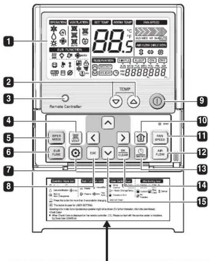
Please attach the inform label inside of the door. Please choose proper language defend on your country.
1 OPERATION INDICATION SCREEN
2 SET TEMPERATURE Button
3 WIRELESS REMOTE (Do not operate) CONTROLLER RECEIVER
• Some products don't receive the wireless signals.
4 VENTILATION Button (Do not operate)
5 OPERATION MODE SELECTION Button
6 SUBFUNCTION Button
7 FUNCTION SETTING Button
8 EXIT Button
9 ON/ OFF Button
10 ROOM TEMPERATURE Button
11 FAN SPEED Button
12 AIR FLOW Button (Do not operate)
13 RESERVATION/ TIME SETTING Button
14 SETTING/ CANCEL Button
15 UP, DOWN, LEFT, RIGHT Button
Troubleshooting
| Problem Cause | Remedy | |
| AHU Control Kit does not work | No power supply Check | the electrical connection and voltage of the power supply. |
| Wiring is wrong Check | the electrical connection of the Control kit(Refer to the circuit diagram of the Control Kit) | |
| AHU Control Kit is broken Check | check the electrical and mechanical part. |
Disposal of your old appliance(as per e-waste Rules)
- When this crossed out wheeled bin symbol is depicted on the product and its operator's manual, it means the product is covered by the e-waste Management and Handling Rules, 2011 and are meant to be recycled, dismantled, refurbished or disposed off.
2. Dos
a. The product is required to be handed over only to the authorized recycle for disposal.
b. Keep the product in isolated area, after it becomes non-functional/un-repairable so as to prevent its accidental breakage.
Don't
a. The product should not be opened by the user himself/herself, but only by authorized service personnel.
b. The product is not meant for re-sale to any unauthorized agencies/scrap dealer/kabariwalah.
c. The product is not meant for mixing into household waste stream.
d. Do not keep any replaced spare part(s) from the product in exposed area.
- Any disposal through unauthorized agencies/person will attract action under Environment (Protection) Act 1986.
- This product is complied with the requirement of Hazardous Substances as specified under Rule 13 (1) & (2) of the E-Waste (Management & Handling) Rules, 2011.
- To locate a nearest collection centre or call for pick-up (limited area only) for disposal of this appliance, please contact Toll Free No. 1800-180-9999 for details. All collection centre and pick up facilities are done by third parties with LG Electronics India Pvt. Ltd. Merely as a facilitator. For more detailed information, please visit: http://www.lge.com/in.