9301A - Speaker GENELEC - Free user manual and instructions
Find the device manual for free 9301A GENELEC in PDF.

| Product Type | Active Studio Monitor Speaker |
| Dimensions (H x W x D) | 300 x 200 x 250 mm |
| Weight | 4.5 kg |
| Power Supply | AC 100-240 V, 50/60 Hz |
| Power Consumption | 50 W typical |
| Amplifier Type | Class D |
| Frequency Response | 45 Hz - 25 kHz (-6 dB) |
| Maximum SPL | 105 dB peak |
| Input Connectors | XLR balanced, RCA unbalanced |
| Output Connectors | XLR loop-through |
| Controls | Volume, Bass tilt, Treble tilt, Input sensitivity |
| Protection Features | Overcurrent, overvoltage, thermal shutdown |
| Enclosure Material | Aluminum die-cast |
| Mounting Options | Stand, wall mount, ceiling mount |
| Operating Temperature | 0°C to 35°C |
| Humidity | 0% to 90% non-condensing |
| Cleaning Instructions | Wipe with a dry, soft cloth. Do not use solvents. |
| Safety Warnings | Do not expose to rain or moisture. Use grounded outlet. |
| Spare Parts & Reparability | Contact Genelec authorized service. Use only genuine parts. |
| Country of Origin | Finland |
Frequently Asked Questions - 9301A GENELEC
User questions about 9301A GENELEC
0 question about this device. Answer the ones you know or ask your own.
Ask a new question about this device
Download the instructions for your Speaker in PDF format for free! Find your manual 9301A - GENELEC and take your electronic device back in hand. On this page are published all the documents necessary for the use of your device. 9301A by GENELEC.
USER MANUAL 9301A GENELEC
natural_image
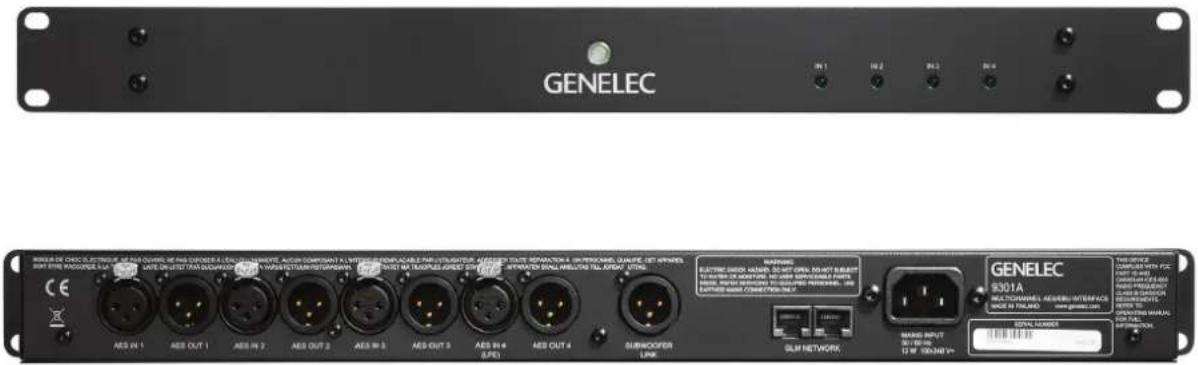
Front view of a black GELEC rack-mounted server unit with internal circuit diagram (no readable text or symbols)Genelec 9301A Multichannel AES/EBU Interface
text_image
GENELEC RISMA DE CHOC ELECTRIGUE OF ONE COUNC MEING CONDER A LUX ELLINOUS MEETING ACSTRUMENTS A LUX ELLINOUS MEETING MEETING MEETING MEETING MEETING MEETING MEETING MEETING MEETING MEETING MEETING MEETING MEETING MEETING MEETING MEETING MEETING MEETING MEETING MEETING MEETING MEETING MEETING MEETING MEETING MEETING MEETING MEETING MEETING MEETING MEETING MEETING MEETING MEETING MEETING MEETING MEETING MEETING MEETING MEETING MEETING MEETING MEETING MEETING MEETING MEETING MEETING MEETING MEETING MEETING ME Theater AEE IN 1 AEE OUT 1 AEE IN 2 AEE OUT 2 AEE IN 3 AEE OUT 3 AEE IN 4 AEE OUT 4 CES 9301A MULTICHANNELS GENERI INTERFACE MARE IN FLAND GENELEC 9301A MULTICHANNELS GENERI INTERFACE MARE IN FLAND GENELEC 9301A MULTICHANNELS GENERI INTERFACE MARE IN FLAND GENELEC 9301A MULTICHANNELS GENERI INTERFACE MARE IN FLAND GENELEC 9301A MULTICHANNELS GENERI INTERFACE MARE IN FLAND GENELECIntroduction
Congratulations and thank you for purchasing the Genelec 9301A multichannel AES/EBU interface intended for 7300 series subwoofers. This manual addresses the setting up and use of the Genelec 9301A.
The low frequencies in multichannel digital audio AES/EBU signals can be monitored by using the 9301A connected to one or more 7300 series smart active monitoring (SAM) subwoofers, for example products 7360A and 7370A. These products have one built-in AES/EBU input and one output, enabling direct monitoring of two digital audio channels. The 9301A multichannel AES/EBU interface expands the digital audio connectivity to 8 audio channels or to 7.1 channels when the low frequency effects (LFE) channel is also used.
The 9301A unit connects to a subwoofer with a simple one-cable link. This cable is an AES/EBU cable and carries the sum of all the main channel inputs and the LFE channel (if used) as the two AES/EBU subframes.
The AES/EBU output on the 7300-series subwoofer connector panel allows easy daisy-chaining using a single cable onwards to multiple subwoofers to enhance and increase the subwoofer acoustic output capacity.
text_image
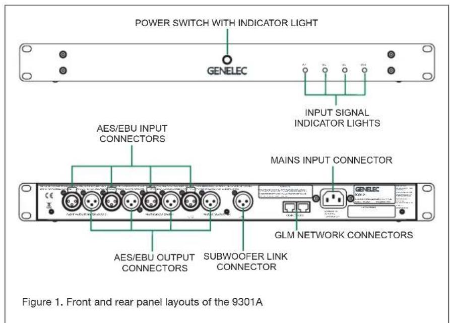
POWER SWITCH WITH INDICATOR LIGHT GENELEC INPUT SIGNAL INDICATOR LIGHTS AES/EBU INPUT CONNECTORS MAINS INPUT CONNECTOR AES/EBU OUTPUT CONNECTORS SUBWOOFER LINK CONNECTOR GLM NETWORK CONNECTORS Figure 1. Front and rear panel layouts of the 9301AThe GLM (Genelec Loudspeaker Manager) software manages the 9301A and sets the correct settings to enable communication between the 9301A and a 7300 series subwoofer.
Each 9301A is supplied with a mains cable, one 5 m GLM network cable and an operating manual. Before connecting up,
ensure that the mains power is switched off.
The energy saving Intelligent Signal Sensing (ISS) function can be turned on in the 9301A to put it automatically into a power save state when no AES/EBU input signal is present. In the power save state the 9301A consumes less than one watt of power. Upon sensing an AES/EBU input signal the
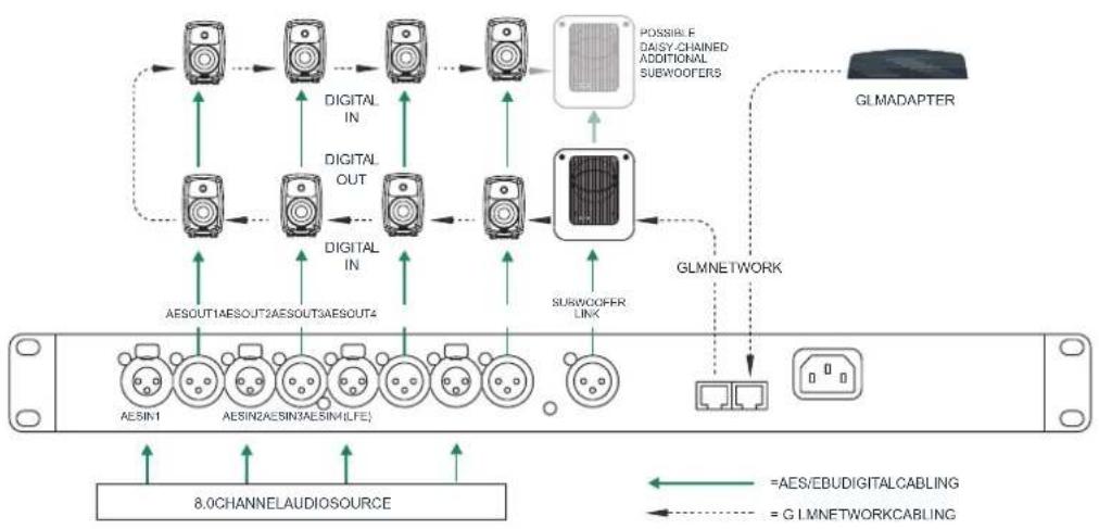
Figure 2. Audio and GLM network cabling for an 8.0 channel system. In this configuration the 9301A routes the sum of all eight channel inputs to the subwoofer.
flowchart
graph TD
    A["8.0CHANNELAUDIOSOURCE"] --> B["AESIN1"]
    A --> C["AESIN2AESIN3AESIN4LE"]
    A --> D["AESOUT1AESOUT2AESOUT3AESOUT4"]
    A --> E["AESOUT4"]
    A --> F["DIGITAL IN"]
    A --> G["DIGITAL OUT"]
    A --> H["SUBWOOFER LINK"]
    A --> I["PLUSIBLE DAISY-CHAINED ADDITIONAL SUBWOOFERS"]
    A --> J["GLMNETWORK"]
    J --> K["GLMADAPTER"]
    style A fill:#f9f,stroke:#333
    style B fill:#ccf,stroke:#333
    style C fill:#ccf,stroke:#333
    style D fill:#ccf,stroke:#333
    style E fill:#ccf,stroke:#333
    style F fill:#ccf,stroke:#333
    style G fill:#ccf,stroke:#333
    style H fill:#ccf,stroke:#333
    style I fill:#ccf,stroke:#333
    style J fill:#ccf,stroke:#333
    style K fill:#ccf,stroke:#333
    style_L["=AES/EBUDIGITALCABLING"] --> M["=GLMNETWORKCABLING"]
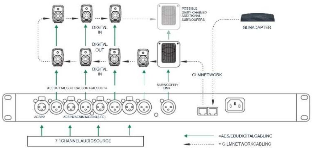
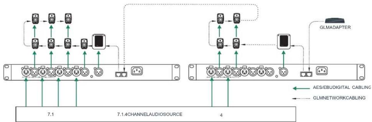
Figure 3. Audio and GLM network cabling for a 7.1 channel system. In this configuration the 9301A routes the sum of all eight channel inputs and the LFE channel content to the subwoofer.
flowchart
graph TD
    A["Device 1"] -->|AESOUT1AESOUT2AESOUT3AESOUT4| B["Digital IN"]
    C["Device 2"] -->|AESIN1AESIN2AESIN3AESIN4(LFE)| D["Digital OUT"]
    E["Device 3"] -->|AESOUT4AESOUT5AESOUT6AESOUT7| F["Digital IN"]
    G["Device 4"] -->|AESOUT9AESOUT10AESOUT11AESOUT12AESOUT13AESOUT14| H["Subwoofer LIVA"]
    I["Device 5"] -->|AESOUT15AESOUT16AESOUT17AESOUT18AESOUT19AESOUT20AESOUT21AESOUT22AESOUT23AESOUT24| J["Possible Daisy-Channel Additional Subwoofer"]
    K["Device 6"] -->|AESIN1AESIN2AESIN3AESIN4(LFE)| L["Subwoofer LIVA"]
    M["Device 7"] --> N["7.1CHANNELAUDIO SOURCE"]
    O["GLMNDAPTER"] --> P["GLMNETWORK"]
    P --> Q["HLMNDAPTER"]
    style A fill:#f9f,stroke:#333
    style C fill:#f9f,stroke:#333
    style E fill:#f9f,stroke:#333
    style G fill:#f9f,stroke:#333
    style I fill:#f9f,stroke:#333
    style M fill:#f9f,stroke:#333
    style N fill:#f9f,stroke:#333
    style O fill:#f9f,stroke:#333
    style P fill:#ccf,stroke:#333
    style Q fill:#ccf,stroke:#333
    style L fill:#ccf,stroke:#333
    style N fill:#ccf,stroke:#333
    style A fill:#fff,stroke:#333
    style C fill:#fff,stroke:#333
    style E fill:#fff,stroke:#333
    style F fill:#fff,stroke:#333
    style G fill:#fff,stroke:#333
    style H fill:#fff,stroke:#333
    style I fill:#fff,stroke:#333
    style J fill:#fff,stroke:#333
    style K fill:#fff,stroke:#333
    style L fill:#fff,stroke:#333
    style M fill:#fff,stroke:#333
    style N fill:#fff,stroke:#333
    style O fill:#fff,stroke:#333
    style P fill:#fff,stroke:#333
    style Q fill:#fff,stroke:#333
    style R fill:#fff,stroke:#333
    style S fill:#fff,stroke:#333
    style T fill:#fff,stroke:#333
    style U fill:#fff,stroke:#333
    style V fill:#fff,stroke:#333
    style W fill:#fff,stroke:#333
    style X fill:#fff,stroke:#333
    style Y fill:#fff,stroke:#333
    style Z fill:#fff,stroke:#333
flowchart
graph TD
    subgraph_Channel1["7.1 CHANNELAUDIO SOURCE"]
        A["Node"] --> B["Node"]
        B --> C["Node"]
        C --> D["Node"]
        D --> E["Node"]
        E --> F["Node"]
        F --> G["Node"]
        G --> H["Node"]
        H --> I["Node"]
        I --> J["Node"]
        J --> K["Node"]
        K --> L["Node"]
        L --> M["Node"]
        M --> N["Node"]
        N --> O["Node"]
        O --> P["Node"]
        P --> Q["Node"]
        Q --> R["Node"]
        R --> S["Node"]
        S --> T["Node"]
        T --> U["Node"]
        U --> V["Node"]
        V --> W["Node"]
        W --> X["Node"]
        X --> Y["Node"]
        Y --> Z["Node"]
        Z --> AA["Node"]
        AA --> AB["Node"]
        AB --> AC["Node"]
        AC --> AD["Node"]
        AD --> AE["Node"]
        AE --> AF["Node"]
        AF --> AG["Node"]
        AG --> AH["Node"]
        AH --> AI["Node"]
        AI --> AJ["Node"]
        AJ --> AK["Node"]
        AK --> AL["Node"]
        AL --> AM["Node"]
        AM --> AN["Node"]
        AN --> AO["Node"]
        AO --> AP["Node"]
        AP --> AQ["Node"]
        AQ --> AR["Node"]
        AR --> AS["Node"]
        AS --> AT["Node"]
        AT --> AU["Node"]
        AU --> AV["Node"]
        AV --> AW["Node"]
        AW --> AX["Node"]
        AX --> AY["Node"]
        AY --> AZ["Node"]
        AZ --> BA["Node"]
        BA --> BB["Node"]
        BB --> BC["Node"]
        BC --> BD["Node"]
        BD --> BE["Node"]
        BE --> BF["Node"]
        BF --> BG["Node"]
        BG --> BH["Node"]
        BH --> BI["Node"]
        BI --> BJ["Node"]
        BJ --> BK["Node"]
        BK --> BL["Node"]
        BL --> BM["Node"]
        BM --> BN["Node"]
        BN --> BO["Node"]
        BO --> BP["Node"]
        BP --> BQ["Node"]
        BQ --> BR["Node"]
        BR --> BS["Node"]
        BS --> BT["Node"]
        BT --> BU["Node"]
        BU --> BV["Node"]
        BV --> BW["Node"]
        BW --> BX["Node"]
        BX --> BY["Node"]
        BY --> BZ["Node"]
        BZ --> CA["Node"]
        CA --> CB["Node"]
        CB --> CC["Node"]
        CC --> CD["Node"]
        CD --> CE["Node"]
        CE --> CF["Node"]
        CF --> CG["Node"]
        CG --> CH["Node"]
        CH --> CI["Node"]
        CI --> CJ["Node"]
        CJ --> CK["Node"]
        CK --> CR["Node"]
        CR --> CS["Node"]
        CS --> CT["Node"]
        CT --> CU["Node"]
        CU --> CV["Node"]
        CV --> CW["Node"]
        CW --> CX["Node"]
        CX --> CY["Node"]
        CY --> CZ["Node"]
Figure 4. Audio and GLM network cabling for a 7.1.4 channel system. Even larger systems can be configured by using multiple 9301As.
9301A automatically wakes up to its normal operation mode. The wait until entering the ISS power save can be configured using the GLM software. When ISS is active you can have your monitoring system ready for action at all times.
Installation
Connections
Two GLM Network connectors are available for computer management using the Genelec Loudspeaker Manager (GLM) software. This software can support analog and digital audio systems with up to 45 monitors and subwoofers.
Four AES/EBU input/output pairs from AES IN 1 to AES IN 4 are available for digital audio signals. Outputs 1 to 4 are a bit-to-bit copy of the input digital audio data and will typically be connected to the satellite monitors. This retains the original signal quality without any modification.
Always ensure that any LFE source is fed into input AES IN 4 of the 9301A. The subframe carrying the LFE channel content can be assigned using the GLM software. Please note that this content is also available at the AES OUT 4 as all the AES OUT connectors carry a bit-to-bit copy of the input audio. This means that the LFE content along with other digital audio data is available for devices connected to the output.
The mains input supports a wide mains voltage range (100-240 VAC, 50-60 Hz) and enables the 9301A to be plugged in anywhere globally. If the mains power is provided with a generator, inverter or certain lower-quality UPS devices, we recommend filtering of the mains power voltage harmonics and taking care that the voltage supply is stable.
Controls And Adjustments
On the outside of the unit there are a power switch and four lights, one for each AES/EBU input. The power switch indicates that the power is on. When the light is flashing continuously, the 9301A settings are being edited with the GLM software. When the input channel lights are lit a valid AES/EBU input has been detected. If the light is off, there is a problem with the AES/EBU data or there is no valid AES/EBU input. See Table 1 for a list of light functions.
In the GLM management software, the
text_image
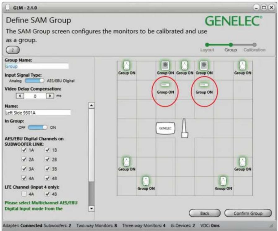
GLM - 2.1.0 Define SAM Group GENELEC® The SAM Group screen configures the monitors to be calibrated and use as a group. Layout Group Calibration Group Name: Group Input Signal Type: Analog AES/EBU Digital Video Delay Compensation: 0 ms Name: Left Side 9301A In Group: OFF ON AES/EBU Digital Channels on SUBWOOFER LINK: ✓ 1A ✓ 1B ✓ 2A ✓ 2B ✓ 3A ✓ 3B ✓ 4A ✓ 4B LFE Channel (input 4 only): 4A ✓ 4B Please select Multichannel AES/EBU Digital Input mode from the Back Confirm Group Group ON Group ON Group ON Group ON Group ON Group ON GENELEC Group ON Group ON Group ON Back Confirm Group Adapter: Connected Subwoofers: 2 Two-way Monitors: 8 Three-way Monitors: 4 G-Devices: 2 VDC: 0msFigure 5. During the Setup Layout we suggest that the 9301As are placed under or above the subwoofers they are connected for easy identification. The "AES/EBU Digital Channels on SUBWOOFER LINK" section allows choosing the input channels to be bass managed. The default selection includes all inputs.
text_image
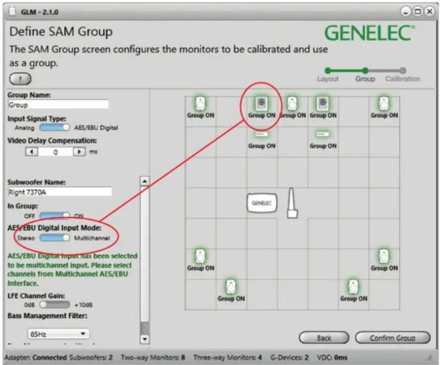
GLM - 2.1.0 Define SAM Group The SAM Group screen configures the monitors to be calibrated and use as a group. GENELEC® Group Name: Group Input Signal Type: Analog AES/EBU Digital Video Delay Compensation: 0 ms Subwoofer Name: Right 7370A In Group: OFF ON AES/EBU Digital Input Mode: Stereo Multichannel AES/EBU Digital Input has been selected to be multichannel input. Please select channels from Multichannel AES/EBU Interface. LFE Channel Gain: 0dB +10dB Bass Management Filter: 85Hz Back Confirm Group Group ON Group ON Group ON Group ON Group ON Group ON GENELEC Group ON Group ON Group ON Group ONFigure 6. During the Group Define stage of GLM Setup, any subwoofer that is connected via Subwoofer Link to 9301A is automatically identified as "Multichannel". Respectively, if a 9301A is not used, the setting is automatically "Stereo".
9301A controls are embedded into the subwoofer controls.
Use With GLM ^TM Management Network
The 9301A is fully compatible with Genelec Loudspeaker Manager GLM ^™ software and the proprietary Genelec monitor management network and Genelec SAM monitors. More information about the use with the GLM ^™ network is available in the SAM System Operating Manual.
System setup
The setup is easy and consists of the following steps:
- Connect the digital audio to the input connectors. If you are using the LFE signal, connect the cable carrying the LFE to AES/EBU 4 connector. Continue with cables from the respective outputs to the monitors. Use cables intended for carrying AES/EBU digital audio. Genelec discourages the use of standard analogue microphone cables as this may reduce system performance.
- Connect the SUBWOOFER LINK output to a subwoofer's DIGITAL IN connector. This creates a link for the subwoofer to input a sum of all input signals.
- Connect CAT5 (RJ45) cables between the 9301A and every monitor and subwoofer. Finally connect to the management network input of a GLM Adapter device (see Figure 2 and 3). Notice that the order of connecting devices is not significant.
- Connect the GLM Adapter device to computer USB connector.
You will find all your devices initially in the product stack of the GLM software. When you find the 9301A in the product stack, drag and drop it to an area on the Layout grid adjacent to where the subwoofer will be placed (see Figure 5).
In case you have multiple 9301A units, observe that when you click with the mouse on a 9301A icon, the front panel light on this 9301A starts flashing, indicating the 9301A that is selected in the GLM software. This can help in identification.
When "Input Signal Type" of the Group is changed to AES/EBU Digital, all 9301As are automatically activated to be part of the group. At the same time the "AES/EBU Digital Input Mode" of all 7300 series subwoofers are turned to Multichannel
| Indicator, colour Colour, indication | Indication | |
| Power switch | Solid green | Power on, normal state and operation |
| Blinking green GLM is adjusting | the 9301A | |
| Green blink every 10 seconds | The 9301A is in ISS power saving state | |
| No light Power off | ||
| Input signal indicator light | Solid green | Valid AES/EBU signal detected, receiving |
| No light No input detected |
Table 1. Front panel indicator light functions
| SPECIFICATIONS | |
| Weight 2 kg (4.4 lbs) | |
| Dimensions:HeightWidthDepth | 44 mm (1 11/16 in)466 mm (18 3/8 in)211 mm (8 5/16 in) |
| Mains voltage 100...240 VAC (50...60 Hz) | |
| Mains tolerance +/- 10 % | |
| Power consumptionISS power saving modelleFull operation | 1 W1 W2 W |
| Digital audio input connectors 4 XLR female | |
| Digital audio input impedance 110 Ohm | |
| Digital audio output connectors | 5 XLR male |
| Digital audio format | AES/EBU (AES3-2003)Can also be used with S/P-DIF and AES3id signals when impedance converters are used |
| Digital audio word length | Minimum 16 bits, maximum 24 bits.Fixed point, AES/EBU format |
| Digital audio sample rate | Minimum 32 kHz, maximum 192 kHz.Supports single-wire AES/EBU audio,does not support dual wire AES/EBU audio |
mode to ensure that multichannel signal is reproduced correctly by subwoofers. If all 9301A devices are set as Group Off then the "AES/EBU Digital Input Mode" of all 7300 series subwoofers is automatically switched to Stereo mode to play normal AES/EBU digital stereo content.
When the LFE channel is used, select the subframe A or B carrying the LFE audio channel. Also, select the “+10 dB” setting for the LFE input when you want the subwoofer to increase the level of the LFE audio channel by 10 dB relative to the main channels.
As a default, all AES/EBU input channels
are selected in the 9301 Group Define panel. If you do not want all inputs to be bass managed, turn off the inputs you want to exclude. This can be done by removing the respective tick marks under "AES/EBU Digital Channels on the SUBWOOFER LINK" section of the GLM (see figure 5). Note that one AES/EBU cable carries two digital audio channels.
To acoustically calibrate your setup, place the Genelec measurement microphone on a microphone stand. Put the microphone at the listening location pointing upwards and its top at ear height. Then follow the instructions in the GLM software to measure
and compensate your monitors and subwoofers.
If you want, you can save the acoustic calibration settings into the monitors, subwoofers, and 9301A units. This enables the use of the calibration data with the GLM network disconnected. Removing the GLM network cable and powering down and up the 9301A and other products on the network enables the use of the stored settings. The settings can be stored into the 9301A using the Genelec Loudspeaker Manager software menu item "Store | Store the Current Group Settings...".
To operate the system without having the computer connected on the GLM network, remove the USB cable connecting to the GLM adapter, power down and then up the 9301A and other devices on your system. This enables the stored settings. Please note that the monitors and subwoofers have a switch for selecting the use of the stored settings, and this switch must be set ON.
Returning to factory settings
The room specific settings stored in a 9301A can be erased by keeping the power switch depressed for more than 10 seconds. This returns the 9301A to the factory settings.
Operating Environment
The 9301A is designed for indoor use only. The permissible ambient temperature is 15-35 degrees Celsius (50-95°F) and relative humidity 20% to 80% (noncondensing). When the product has been stored or transported in cool environment and is taken into a warm room, wait 0.5-1 hours before opening any packing to prevent condensation of humidity before connecting to mains power. Sufficient cooling must be ensured. No minimum clearance is needed.
Maintenance
There are no user serviceable parts inside the 9301A. Maintenance or repair must only be done by Genelec certified service personnel.
Guarantee
Genelec guarantees the 9301A for two years against manufacturing faults or defects altering performance. Refer to the reseller for full sales and guarantee terms.
Safety Considerations
The 9301A has been designed in accordance with international safety standards. To ensure safe operation, the following warnings and precautions must be observed:
- Servicing and adjustment must only be performed by Genelec certified service personnel.
- The enclosure must not be opened.
- Do not use this product with a mains cable or mains outlet having no protective earth (potential equalizing) connection as doing so may result in personal injury.
- To prevent fire or electric shock, do not expose the unit to water or moisture.
- Do not place objects filled with liquid, such as vases, on the 9301A or near it.
- The 9301A is not completely disconnected from the mains power unless the mains cable is removed from the device or the mains outlet.
Compliance to FCC Rules
This device complies with part 15 of the FCC Rules. Operation is subject to the following two conditions:
- This device may not cause harmful interference, and
- This device must accept any interference received, including interference that may cause undesired operation.
Note: This equipment has been tested and found to comply with the limits for a Class B digital device, pursuant to part 15 of the FCC Rules. These limits are designed to provide reasonable protection against harmful interference in a residential installation. This equipment generates, uses, and can radiate radio frequency energy and, if not installed and used in accordance with the instructions, may cause harmful interference to radio communications. There is no guarantee that interference will not occur in a particular installation. If this equipment does cause harmful interference to radio or television reception, which can be determined by turning the equipment off and on, the user is encouraged to try and correct the interference by one or more of the following measures:
- Reorient or relocate the receiving antenna.
- Increase the separation between the
equipment and receiver.
- Connect the equipment into an outlet on a circuit different from that to which the receiver is connected.
- Consult the dealer or an experienced radio/TV technician for help.
Modifications not expressly approved by the manufacturer can void the user's authority to operate the equipment under FCC rules.
Genelec Document D0116R003. Copyright Genelec Oy 12.2016. All data subject to change without prior notice
www.genelec.com
GENELEC®
International enquiries:
Genelec, Olvitie 5
FIN-74100, lisalmi, Finland
Phone +358 17 83881
Fax +358 17 812 267
Email genelec@genelec.com
In the U.S. please contact:
Genelec, Inc., 7 Tech Circle
Natick, MA 01760, USA
In China please contact:
Beijing Genelec Audio Co, Ltd
Room 101, 1st Floor Building 71 B33
Universal Business Park
No.10 Jiuxianqiao Road, Chaoyang District,
Beijing 100015, China
Phone +86 (10) 5823 2014, Post code 100015
Email genelec.china@genelec.com
In Sweden please contact
Genelec Sverige
Ellipsvägen 10B
P.O. Box 5521, S-141 05 Huddinge
Phone +46 8 449 5220
Fax +46 8 708 7071
Email info@genelec.com