HDL18-AS - Loudspeaker RCF - Free user manual and instructions
Find the device manual for free HDL18-AS RCF in PDF.


| Product Type | Active Subwoofer |
| Brand | RCF |
| Model | HDL18-AS |
| Woofer Size | 18 inches |
| Built-in Amplifier | Yes, Class D |
| Power Output (Peak) | 2000 W |
| Frequency Response | 30 Hz - 120 Hz |
| Maximum SPL | 132 dB |
| Dimensions (W x H x D) | 505 mm x 550 mm x 600 mm |
| Weight | 40 kg |
| Power Supply | AC 100-240 V, 50/60 Hz |
| Input Connectors | XLR, Jack |
| Output Connectors | XLR Link Out |
| DSP Features | Built-in crossover, EQ, limiter |
| Enclosure Material | Plywood with polyurea coating |
| Grille | Powder-coated perforated steel |
| Maintenance | Clean with dry cloth; do not use solvents |
| Safety | Use grounded outlet; do not expose to rain |
| Spare Parts | Contact RCF authorized service center |
| General Information | Professional subwoofer for PA systems |
Frequently Asked Questions - HDL18-AS RCF
User questions about HDL18-AS RCF
0 question about this device. Answer the ones you know or ask your own.
Ask a new question about this device
Download the instructions for your Loudspeaker in PDF format for free! Find your manual HDL18-AS - RCF and take your electronic device back in hand. On this page are published all the documents necessary for the use of your device. HDL18-AS by RCF.
USER MANUAL HDL18-AS RCF
- All the precautions, in particular the safety ones, must be read with special attention, as they provide important information.
2. POWER SUPPLY FROM MAINS
The mains voltage is sufficiently high to involve a risk of electrocution; install and a. connect this product before plugging it in.
Before powering up, make sure that all the connections have been made correctly and b. the voltage of your mains corresponds to the voltage shown on the rating plate on the unit, if not, please contact your RCF dealer.
The metallic parts of the unit are earthed through the power cable. An apparatus with c. CLASS I construction shall be connected to a mains socket outlet with a protective earthing connection.
Protect the power cable from damage; make sure it is positioned in a way that it d. cannot be stepped on or crushed by objects.
To prevent the risk of electric shock, never open this product: there are no parts inside e. that the user needs to access.
"POWER ON" switch is a disconnecting device from AC main power and must be f. easily accessible after the installation and during the using of equipment.
- Make sure that no objects or liquids can get into this product, as this may cause a short circuit.
This apparatus shall not be exposed to dripping or splashing. No objects filled with liquid, such as vases, shall be placed on this apparatus. No naked sources (such as lighted candles) should be placed on this apparatus.
- Never attempt to carry out any operations, modifications or repairs that are not expressly described in this manual.
Contact your authorized service centre or qualified personnel should any of the following occur:
The product does not function (or functions in an anomalous way). -
The power cable has been damaged. -
Objects or liquids have got in the unit. -
The product has been subject to a heavy impact. -
-
If this product is not used for a long period, disconnect the power cable.
-
If this product begins emitting any strange odours or smoke, switch it off immediately and disconnect the power cable.
-
Do not connect this product to any equipment or accessories not foreseen.
For suspended installation, only use the dedicated anchoring points and do not try to hang this product by using elements that are unsuitable or not specific for this purpose. Also check the suitability of the support surface to which the product is anchored (wall, ceiling, structure, etc.), and the components used for attachment (screw anchors, screws, brackets not supplied by RCF etc.), which must guarantee the security of the system / installation over time, also considering, for example, the mechanical vibrations normally generated by transducers.
To prevent the risk of falling equipment, do not stack multiple units of this product unless this possibility is specified in the user manual.
- RCF S.p.A. strongly recommends this product is only installed by professional qualified installers (or specialised firms) who can ensure correct installation and certify it according to the regulations in force.
The entire audio system must comply with the current standards and regulations regarding electrical systems.
- Supports and trolleys
The equipment should be only used on trolleys or supports, where necessary, that are
IMPORTANT

recommended by the manufacturer. The equipment / support / trolley assembly must be moved with extreme caution. Sudden stops, excessive pushing force and uneven floors may cause the assembly to overturn.
-
There are numerous mechanical and electrical factors to be considered when installing a professional audio system (in addition to those which are strictly acoustic, such as sound pressure, angles of coverage, frequency response, etc.).
-
Hearing loss
Exposure to high sound levels can cause permanent hearing loss. The acoustic pressure level that leads to hearing loss is different from person to person and depends on the duration of exposure. To prevent potentially dangerous exposure to high levels of acoustic pressure, anyone who is exposed to these levels should use adequate protection devices. When a transducer capable of producing high sound levels is being used, it is therefore necessary to wear ear plugs or protective earphones. See the manual technical specifications to know the maximum sound pressure level.
IMPORTANT NOTES
To prevent the occurrence of noise on line signal cables, use screened cables only and avoid putting them close to:
Equipment that produces high-intensity electromagnetic fields. -
Power cables. -
Loudspeaker lines. -
IMPORTANT NOTES

OPERATING PRECAUTIONS

OPERATING PRECAUTIONS
- Place this product far from any heat sources and always ensure an adequate air circulation around it.
Do not overload this product for a long time. -
Never force the control elements (keys, knobs,etc.). -
- Do not use solvents, alcohol, benzene or other volatile substances for cleaning the external parts of this product.
IMPORTANT NOTES
Before connecting and using this product, please read this instruction manual carefully and keep it on hand for future reference. The manual is to be considered an integral part of this product and must accompany it when it changes ownership as a reference for correct installation and use as well as for the safety precautions. RCF S.p.A. will not assume any responsibility for the incorrect installation and / or use of this product.
WARNING: to prevent the risk of fire or electric shock, never expose this product to rain or humidity.
IMPORTANT NOTES

WARNING

The concept of this unique speaker derives from the touring industry, bringing in a compact cabinet all the experience of RCF professional sound.
The vocals are natural, the sound is clear at longer distances, the spl power is stable at very high levels.
The RCF Precision transducers equipping D LINE have been representing for decades the ultimate performance, the highest power handling and the mos advanced technology in the professional and touring industry.
The high power woofer delivers extremely accurate punchy bass, the custom made compression driver offers a transparent midrange and extreme fidelity.
RCF Class-D power amplifiers technology packs huge performance operating with high efficiency into a lightweight solution. D LINE amplifiers deliver ultra fast attack, realistic transient response and impressive audio performance.
The integrated DSP manages crossover, equalisation, soft limiter, compressor and dynamic bass boost.
D LINE cabinets are moulded on a special polypropylene composite material designed to dampen down vibrations even at maximum volume settings.
From moulding to the final texture, D LINE offers the maximum reliability and strength for the intensive use on the road.
THE HDL18-AS ACTIVE FLYABLE HIGH POWER SUBWOOFER
The HDL18-AS is a compact, flyable high power subwoofer, designed to integrate seemlessly into a HDL 20-A flown array.
The bass reflex design guarantees a deep, linear power response while the 4" voice coil vented design woofer offers the minimum of power compression. The system provides integrated mechanics compatible with the HDL 20-A array module.
The HDL18-AS features:
2000 Watt Peak power - 1000 Watt RMS. -
135 dB max SPL. -
30 Hz - 140 kHz frequency response. -
1 x 18" Woofer. -
DSP controlled Input section with selectable presets. -
Tour grade safe and solid variable mechanics, compatible with HDL 20-A.
- Designed to compliment the HDL 20-A speaker system.
- Baltic birch tour grade cabinet.
The HDL18-AS input section provides:
- IN/OUT XLR connectors.
- Crossover Output XLR connector.
- Volume control (linear potentiometer).
- Crossover setup (90 Hz - 140 Hz).
- Low frequencies high pass set-up (30 Hz - 45 Hz).
- Phase switch.
- Link crossover switch.
- 3 status LEDs.
The HDL18-AS amplifier section features:
- 1x1000 Watt Digital anamplifier module.
-Powercon AC input connector. - Floating aluminium panel.
D LINE TOURING AUDIO SOLUTIONS
HDL18-AS ACTIVE FLYABLE HIGH POWER SUBWOOFER
REAR PANEL

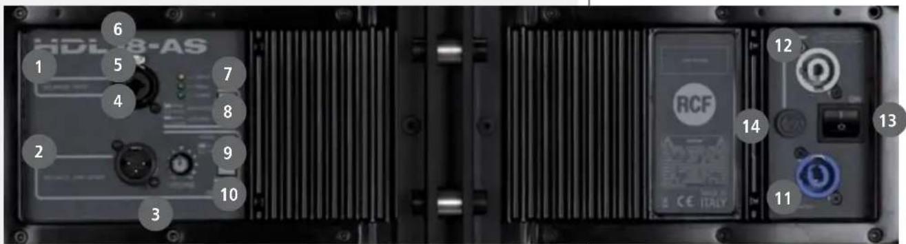
1 MAIN XLR INPUT (BAL/UNBAL). The system accept female XLR input connectors and line level signals from a mixing console or other signal source.
2 LINK XLR OUTPUT. The output XLR male connector provides a loop trough for speakers daisy chaining and crossover out if LINK/XOVER switch is pressed.
3 VOLUME. Controls the volume of the power amplifier. The control ranges from - (maximum attenuation) to the MAX level (maximum output).
4 POWER INDICATOR. Power on indicator. When the power cord is connected and the power switch is turned on this indicator lights green.
5 SIGNAL INDICATOR. The signal indicator lights green if there is signal present on the main XLR input.
6 LIMITER INDICATOR. The amplifier has a built in limiter circuit to prevent clipping of the amplifiers or overdriving the transducers. When the peak clipping circuit is active the LED blinks orange. It is okay if the limit LED blinks occasionally. If the LED blinks frequently or lights continuously, turn down the signal level. The amplifier has a built in RMS limiter. If the RMS limiter is active the LED lights red. The RMS limiter has the purpose to prevent damages the transducers. The speaker shall never be used with the limit indicator red, continuous operation with the RMS protection active can cause damages to the speaker.
7 HIGH PASS. The switch gives the possibility to set high pass filter at 30 Hz or 45 Hz.
8 LOW PASS. The switch gives the possibility to set low pass filter (crossover point) at 90 Hz or 140 Hz.
9 PHASE. The switch gives the possibility to rotate the phase of 180^ (phase reverse).
10 LINK/XOVER. The switch enables the XLR link/xover output to daisy chain the signal or to add the crossover filter to the output signal.
- LINK (daisy chain the input signal).
- ON (add the crossover filter to the output signal).
11 AC POWERCON RECEPTACLE. RCF D Line uses a POWERCON locking 3-pole AC mains. Always use the specific power cord provided in the package.
12 AC POWERCON LINK RECEPTACLE. Use this receptacle to link one or more units.
Always make sure that the maximum current requirement does not exceed the maximum admitted POWERCON current. In case of doubt call the closest RCF SERVICE CENTRE.
13 POWER MAIN SWITCH. The power switch turns the AC power ON and OFF. Make sure that the VOLUME is set to - when you turn on the speaker.
14 FUSE.
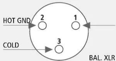
The XLR connectors use the following AES standard:
$$ \text { PIN } 1 = \text { GROUND (SHIELD) } $$
$$ \text { PIN } 2 = \text { HOT } (+) $$
$$ \text { PIN } 3 = \text { COLD } (-) $$
At this point you can connect the power supply cable and the signal cable, but before turning on the speaker make sure that the volume control is at the minimum level (even on the mixer output). It is important that the mixer is already ON before turning on the speaker. This will avoid damage to the speakers and noisy "bumps" due to turning on parts on the audio chain. It is a good practice to always turn on speakers at last and turn them off immediately after the show.
Now you can turn ON the speaker and adjust the volume control to a proper level.
CONNECTIONS
Two aluminium die cast handles with rubber hand-grip are available on each side of the speaker system. The outdoor quality, Baltic birch plywood, cabinet is protected with heavy duty, scratch resistant, polyurea coating.
INSTALLATION

WARNING: never suspend D LINE speakers by there handles. Handles are intended for transportation, not for rigging.
WARNING

WARNING: always make sure that the maximum current requirement does not exceed the maximum admitted POWERCON current. In case of doubt call the closest RCF service centre.
WARNING

MAINS SUPPLY
The system accept mains supply voltage115-230 (+15/-15%) V \~
230 VOLT, 50 HZ SETUP - : FUSE VALUE T 1.6 A - 250V
115 VOLT, 60 HZ SETUP: - FUSE VALUE T 3.15A - 250V
HDL18-AS SUSPENDED
- Suspending loads should be done with extreme caution.
- When deploying a system always wear protective helmets and footwear.
- Never allow people to pass under the system during the installation process.
- Never leave the system unattended during the installation process.
- Never install the system over areas of public access.
- Never attach other loads to the array system.
- Never climb the system during or after the installation.
- Never expose the system to extra loads created from the wind or snow.
WARNING: The system must be rigged in accordance with the laws and regulations of the Country where the system is used. It is responsibility of the owner or rigger to make sure that the system is properly rigged in accordance with Country and local laws and regulations.
WARNING

WARNING: Always check that all the parts of the rigging system that are not provided from RCF are:
WARNING

- appropriate for the application;
- approved, certified and marked;
- properly rated;
- in perfect condition.
WARNING: Each cabinet support the full load of the part of the system below. It is very important that each single cabinet of the system is properly checked.
The suspension system is designed to have a proper Safety Factors (configuration dependent). Using the "RCF Shape Designer" software it is very easy to understand safety factors and limits for each specific configuration. To better comprehend in which safety range the mechanics are working a simple introduction is needed: HDL18-AS mechanics are built with certified UNI EN 10025-95 S 235 JR and S 355 JR Steel. RCF prediction software calculates forces on every single stressed part of the assembly and shows the minimum safety factor for every link.
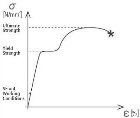
S 235 JR is a structural steel and S 355 has a stress-strain (or equivalent Force-Deformation) curve like the following.
The curve is characterized by two critical points: the Break Point and the Yield Point. The tensile ultimate stress is simply the maximum stress attained. Ultimate tensile stress is commonly used as a criterion of the strength of the material for structural design, but it should be recognized that other strength properties may often be more important. One of these is for sure the Yield Strength. Stress-strain diagram of S 235 JR exhibit a sharp break at a stress below the ultimate strength. At this critical stress, the material elongates considerably with no apparent change in stress. The stress at which this occurs is referred to as the yield point.
Permanent deformation may be detrimental, and the industry adopted 0.2% plastic strain as an arbitrary limit that is considered acceptable by all regulatory agencies. For tension and compression, the corresponding stress at this offset strain is defined as the yield.
S 355 J and S 235 JR characteristic values are R=360 [N/mm2] and R=510 [N/mm2] for Ultimate Strength and Rp0.2=235 [N/mm2] and Rp0.2=355 [N/mm2] for Yield Strength. In our prediction software the Safety Factors are calculated considering the Maximum Stress Limit equal to the Yield Strength, according with many international standards and rules. The resulting Safety Factor is the minimum of all the calculated safety factors, for each link or pin.
This is where you are working with a SF=4:
Depending on local safety regulation and on situation the required safety factor can vary. It is responsibility of the owner or rigger to make sure that the system is properly rigged in accordance with Country and local laws and regulations. The "RCF Shape Designer" software gives detailed information of the safety factor for each specific configuration.
The safety factor is the result of the forces acting on fly bar's and system's front and rear links and pins and depends on many variables:
- number of cabinets;
- fly bar angles;
- angles from cabinets to cabinets. If one of the cited variables change the safety factor MUST BE recalculated using the software before rigging the system.
In case the fly bar is picked up from 2 motors make sure that the fly bar angle is correct. An angle different from the angle used in the prediction software can be potentially dangerous. Never allow persons to stay or pass under the system during the installation process.
When the fly bar is particularly tilted or the array is very curved the centre of gravity can move out from the rear links. In this case the front links are in compression and the rear links are supporting the total weight of the system plus the front compression. Always check very carefully with the "RCF Shape Designer" software all this kind of situations (even with a small number of cabinets).
THE MAXIMUM NUMBER OF SPEAKERS HDL20-A THAT MAY BE SUSPENDED USING THE HDL20-A FRAME IS 16 (SIXTEEN) OR 4 HDL 18-AS + 8 HDL 20-A MAXIMUM OR 8 HDL18-A.
WARNING

"RCF SHAPE DESIGNER" SOFTWARE AND SAFETY FACTOR
line
| ε [%] | σ [N/mm] | |-------|----------| | 0 | 0 | | >0 | Ultimate Strength | | >0 | Yield Strength | | >0 | SF = 4 Working Conditions |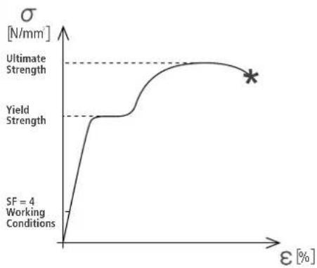
line
| ε [%] | σ [N/mm] | |-------|----------| | 0 | 0 | | >0 | Ultimate Strength | | >0 | Yield Strength | | >0 | SF = 4 Working Conditions |MAXIMUM ARRAY SIZE
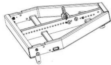
THE HDL18-A FLY BAR
FRONT FLYING BRACKET. Front mounting.
2 QUICK LOCK PIN HOLE. Front mounting (to be used to lock the front bracket before installation).
FRONT BRACKET - TRANSPORT HOLES.
4.ENTRAL PICK UP POINTS.
5he pickup is asymmetric and can be fit in two positions (A and B). A position brings the shackle towards the front. B position allows an intermediate step using the same fixing holes.
6love the pickup bracket in the position suggested by RCF Shape Designer.
71x the pickup bracket with the two pins on the bracket's lanyard to lock the pickup.
8 Check that all the pins are secured and locked.
Rigging the system follow the procedure:
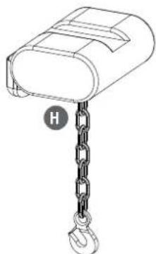
HIGGING CHAIN HOIST.
SERTIFIED SHACKLE.
FLY BAR.
THE HDL18-A FLY BAR FEATURES:
natural_image
Technical line drawing of a mechanical assembly with no visible text or symbols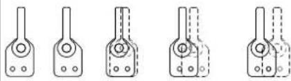
natural_image
Five identical line drawings of a mechanical component with no text or symbols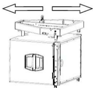
natural_image
Technical line drawing of a mechanical device with two opposing arrows indicating directional movement (no text or symbols)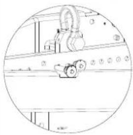
natural_image
Technical line drawing of a mechanical assembly inside a circular frame (no text or symbols)RIGGING PROCEDURE
natural_image
Line drawing of a mailbox with a chain hanging from its side (no text or symbols)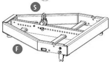
natural_image
Technical line drawing of a mechanical frame assembly with labeled parts S and F (no text or symbols beyond labels)1) Connect the fly-bar F to the chain hoist H (o motors) using the certified shackle. Secure the shackle.
2) Connect the second pin on the front bracket to make sure that the connecting bracket is vertical.
3) Connect the front bracket to the first HDL18-A cabinet using 2 quick lock pins.
4) Reverse and connect the rear bracket to the fly-bar using 1 quick lock pins. The first HDL18-AS has to be fixed always starting at 0° with respect of the frame. No other angles are allowed.
5) Connect the second cabinet to the first always starting from the 2 front brackets.
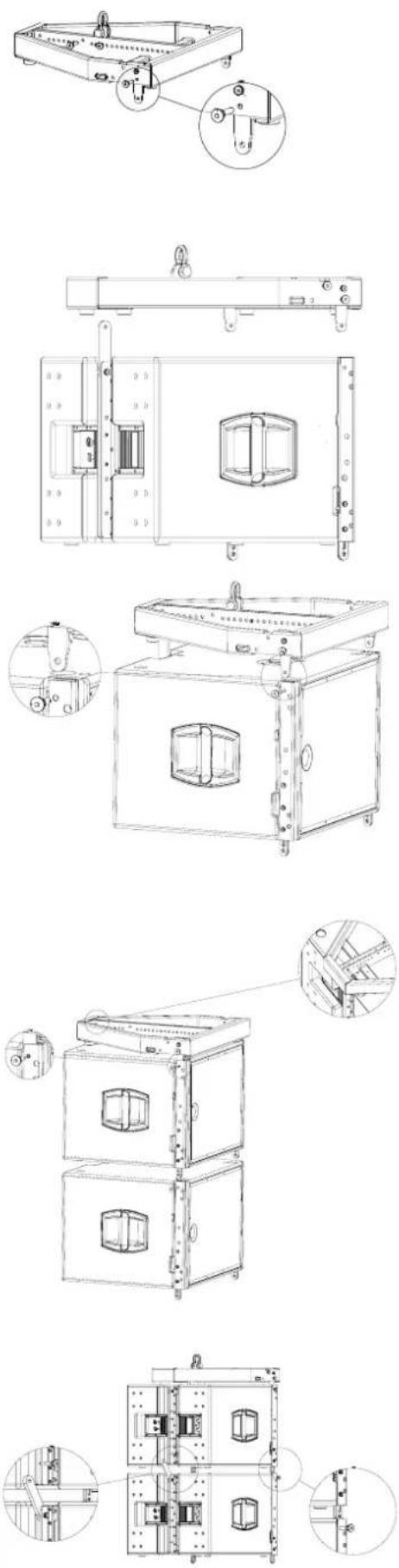
6) Reverse and connect the rear bracket of the second cabinet using the hole.
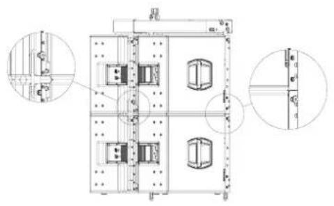
7) Connect all the other HDL20-A cabinets using the accessory linkbar HDL18 to HDL20A (P.N. 13360225).
Fix the linkbar P.N. 13360225 to the HDL 18-AS rear bracket using 2 pins (1 on the subwoofer and 1 on the accessory).
Fix HDL 20-A front to subwoofer brackets using 2 pins.
Fix the HDL 20-A rear bracket to the linkbar P.N. 13360225 using the included 2 pins.
The first HDL 20-A module must be parallel to the subwoofer.
This application allows to link a maximum of 8 HDL 20-A.
natural_image
Technical line drawing of a mechanical assembly with two views (top and side), no visible text or symbols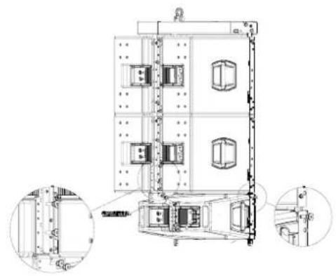
natural_image
Technical line drawing of a multi-level industrial or mechanical assembly with internal components and mounting holes (no text or symbols)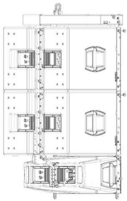
natural_image
Technical line drawing of a multi-level industrial machine or control unit with internal compartments and mounting brackets (no text or symbols)ARRAY SYSTEMS DESIGN
HDL20-A allow users to choose from different face-to-face angle adjustments to create arrays with varying curvature. Thus, designers can create arrays custom-tailored to each venue's profile.
The basic approach to array design dependent on three factors:
- Number of Array Elements;
- Vertical Splay Angles;
- Horizontal Coverage.
Determining the number of elements to use is critical: the number of elements greatly affects the SPL available from the system as well as the uniformity of coverage in both SPL and frequency response. The number of elements profoundly effects the directivity at lower frequencies.
The next easy equation, works as an approximation for flat listening planes.
Coverage (x) ≈ 8n (m) Coverage distance required = x (metres).
Changing the splay angles between cabinets has a significant impact on vertical coverage for the high frequencies, with the result that narrower vertical splay angles produce a higher Q vertical beamwidth, while wider splay lowers the Q at high frequencies. In general, the splay angles do not affect the vertical coverage at lower frequencies.
The curved array system design can be summarized as:
- flat-front HDL20-A s for long throw sections;
- increase curvature as distance decreases;
- add more enclosures for more output.
This approach focuses more transducers mounted on long-throw horns at the farthest seat, gradually focusing fewer transducers as distance decreases. As long as the no gap rule is maintained, arrays constructed according to these principles will provide even SPL and a consistent sonic character throughout the venue without requiring complex processing. This approach, where the same amount of acoustic energy is spread over a larger or smaller vertical angle depending on required throw, typically have the following objectives:
- even horizontal and vertical coverage;
- uniform SPL;
- uniform frequency response;
- sufficient SPL for the application.
This discussion represents, of course, just a basic approach. Given the infinite variety of venues and performers, users will find themselves
needing to solve specific problems in specific situations. RCF Shape Designer software designed to help calculate optimum splay angles, aiming angles, and fly-bar pick points (crucial in aiming the array) for a given venue, will be explained later in this Guide.
ARRAY SYSTEMS DESIGN
RCF Shape Designer is supplied in a zip folder which contains a setup executable file:

setup
Double-click on this and follow the on-screen prompts.
INSTALLING RCF SHAPE DESIGNER
The RCF Shape Designer requires an IBM compatible PC with the Windows® 98, Windows® 98SE, Windows® 2000, Windows® ME, Windows® XP, or Windows NT® operating systems. It is not designed to work with Windows® 3.x, Windows® 95, or Macintosh® operating systems.
Use the RCF Shape Designer for designing HDL20-A arrays. The RCF Shape Designer's primary function is to determine the configuration that will provide the best vertical performance for a given application. Various venue dimensions are entered that allow the RCF Shape Designer to calculate the resultant array performance.
Once you have installed RCF Shape Designer, it will be visible as a shortcut in All Programs via your Windows Start button.

A single click on the RCF Shape Designer tab will open the following page:
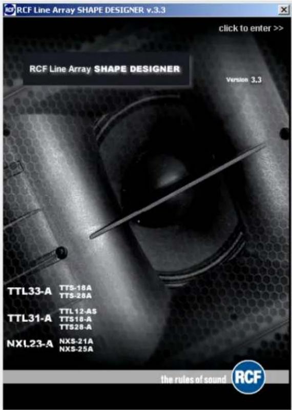
A single click on the window will open the following page:
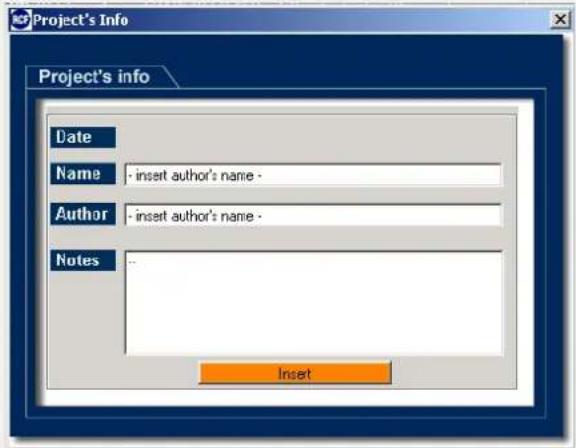
Filling the blank tabs it's possible to start the program.
COMPUTER REQUIREMENTS
INTRODUCTION
USING RCF SHAPE DESIGNER SOFTWARE
ENTERING VENUE DATA
For best results, planes should be used as follows:
FLOOR is used to simulate the main floor area from the stage to a rear bleacher or boundary.
PLANE 1 is used to simulate any audience continuation behind FLOOR (e.g. a rear bleacher) from the end of the main floor to furthest and highest seat below PLANE 2.
PLANE 2 is used to simulate the furthest/highest audience area.
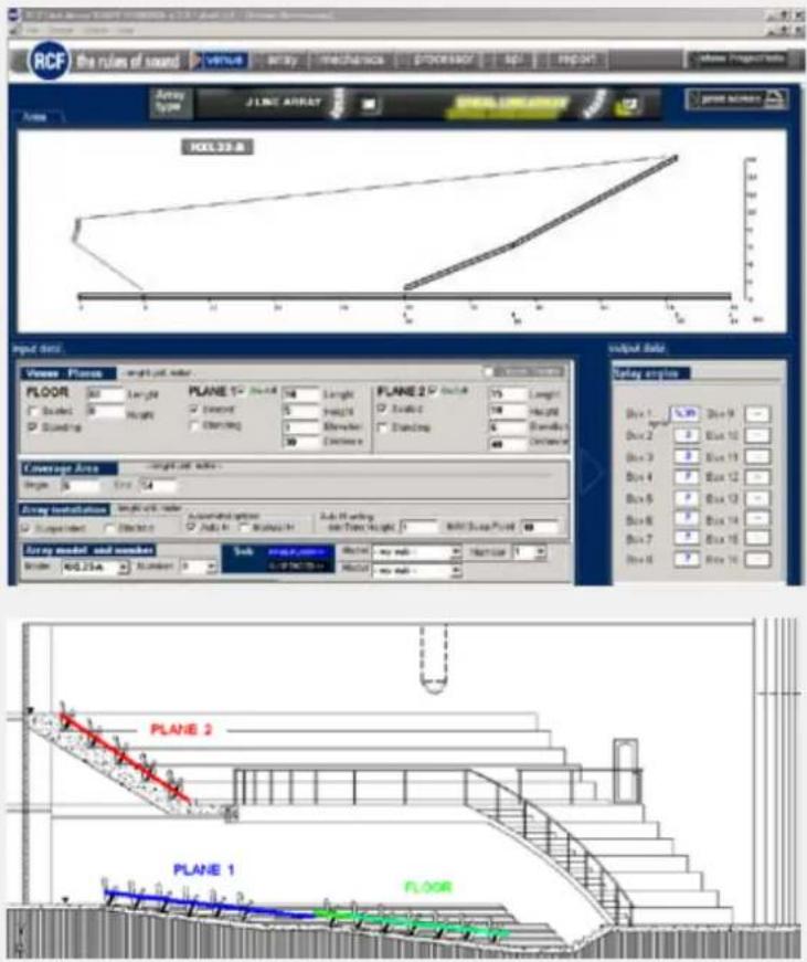
Enter the height, length and elevation of up to three planes.

For all planes Length refers to the horizontal length of that plane.
For all planes Height refers to the height of the rear of the plane.
For PLANES 1 and 2 Elevation refers to the elevation (height) of the front of the plane.
For PLANE 1 and 2 Distance relates to the actual distance from the front of the array to the start of the plane.
For all planes selecting Seated or Standing places ear level at 1.3 or 1.7 m above the respective plane.
Specify the horizontal coverage distances from the front of the array.

Select either Suspended or Stack in the Array installation section to determine how the array is supported.

In Suspended mode the grid is suspended and cabinets are attached beneath.
In Stack mode the grid forms a base and cabinets are placed on top.
COVERAGE
ARRAY INSTALLATION
AUTO H SETTING - MIN TRIM HEIGHT
This is the low limit for the array and is defined as the smallest allowable distance from the lowest point of the array to the ground below
AUTO H SETTING - MAX SUSPENSION POINT
Set this to the maximum array height allowable (usually the highest part of the flying frame). The maximum pick height is usually chosen to allow for the maximum flying point height minus a sensible allowance for any shackles, stingers, bridles or flying hooks. 1m should be allowed for a stinger between each grid flying lug and the relevant motor hook to ensure that motor chain bags do not rest on the grid or top cabinet and upset its tilt angle.
MANUAL H SETTING
In manual installation mode it is possible to enter the height required for flying the system.

Number of cabinets can be set depending also on cabs availability.

VENUE PAGE
- Graphical representations of the array and the venue
- Aiming splay angle between each pair of enclosures
![RCF Line Array Start (S10097) x L8 - started - [Start Dimension] File Edit View Insert Area the rules of sound Venture Array mechanics processor age & reset Point Number FLOOR Length Flange Height Coverage Area Length side Flange Height Coverage Area Length side Range: Bcc: 40 Array interpolation: length and width Annotated options: Bcc: Manual 4 Adaptive setting: width: 500 mm Bcc: 500 mm Bcc: 500 mm Bcc: 500 mm Bcc: 500 mm Bcc: 500 mm Bcc: 500 mm Bcc: 500 mm Bcc: 500 mm Bcc: 500 mm Bcc: 500 mm Bcc: 500 mm Bcc : Bcc : Bcc : Bcc : Bcc : Bcc : Bcc : Bcc : Bcc : Bcc : Bcc : Bcc : Bcc : Bcc : Bcc : Bcc : Bcc : Bcc : Bcc : Bcc : Bcc : Bcc : Bcc : Bcc : Bcc : Bcc : Bcc : Bcc : Bcc : Bcc : Bcc : Bcc : Bcc : Bcc : Bc : Bc : Bc : Bc : Bc : Bc : Bc : Bc : Bc : Bc : Bc : Bc : Bc : Bc : Bc : Bc : Bc : Bc : Bc : Bc : Bc : Bc : Bc : Bc : Bc : Bc : Bc : Bc : Bc : Bc : Bc : Bc : Bc : Bc / Box 1.0 / Box 1.0 / Box 1.0 / Box 1.0 / Box 1.0 / Box 1.0 / Box 1.0 / Box 1.0 / Box 1.0 / Box 1.0 / Box 1.0 / Box 1.0 / Box 1.0 / Box 1.0 / Box 1.0 / Box 1.0 / Box 1.0 / Box 2.0 / Box 3.0 / Box 4.0 / Box 5.0 / Box 6.0 / Box 7.0 / Box 8.0 / Box 9.0 / Box 10.0 / Box 11.0 / Box 12.0 / Box 13.0 / Box 14.0 / Box 15.0 / Box 16.0 / Box 17.0 / Box 18.0 / Box 19.0 / Box 20.0 / Box 21.0 / Box 22.0 / Box 23.0 / Box 24.0 / Box 25.0 / Box 26.0 / Box 27.0 / Box 28.0 / Box 29.0 / Box 30.0 / Box 31.0 / Box 32.0 / Box 33.0 / Box 34.0 / Box 35.0 / Box 36.0 / Box 37.0 / Box 38.0 / Box 39.0 / Box 40.0 / Box 41.0 / Box 42.0 / Box 43.0 / Box 44.0 / Box 45.0 / Box 46.0 / Box 47.0 / Box 48.0 / Box 49.0 / Box 50.0 / Box 51.0 / Box 52.0 / Box 53.0 / Box 54.0 / Box 55.0 / Box 56.0 / Box 57.0 / Box 58.0 / Box 59.0 / Box 60.0 / Box 61.0 / Box 62.0 / Box 63.0 / Box 64.0 / Box 65.0 / Box 66.0 / Box 67.0 / Box 68.0 / Box 69.0 / Box 70.0 / Box 71.0 / Box 72.0 / Box 73.0 / Box 74.0 / Box 75.0 / Box 76.0 / Box 77.0 / Box 78.0 / Box 79.0 / Box 80.0 / Box 81.0 / Box 82.0 / Box 83.0 / Box 84.0 / Box 85.0 / Box 86.0 / Box 87.0 / Box 88.0 / Box 89.0 / Box 90.0 / Box 91.0 / Box 92.0 / Box 93.0 / Box 94.0 / Box 95.0 / Box 96.0 / Box 97.0 / Box 98.0 / Box 99.0 Balance Number Number Number Number Number Number Number Number Number Number Number Number Number Number Number Number Number Number Number Number Number Number Number Number Number Number Number Number Number Number Number Number Number Number Number Number Number Number Number Number Number Number Number Number Number Number Number Number Number Number Percentage values: % Value percentage: % Value percentage: % Value percentage: % Value percentage: % Value percentage: % Value percentage: % Value percentage: % Value percentage: % Value percentage: % Value percentage: % Value percentage: % Value percentage: % Value percentage: % Value percentage: % Value percentage: % Value percentage: % Value percentage: % Value percentage: % Value percentage: % Value percentage: % Value percentage: % Value percentage: % Value percentage: % Value percentage: % Value percentage: % Value percentage: %.% Output data: Output samples: Box Input: Box-1: Box-2: Box-3: Box-4: Box-5: Box-6: Box-7: Box-8:](/content/2026/05/1053368/images/bc6b01caf1372f0d7ac7b82dca3fbd9c24bbbe62a17adf6b95d600d6f800a1a3.jpg)
- Height of the array and trim height to the bottom of the array from the floor
- Pick Point on the Fly-Bar to achieve the calculated array angle when suspended
- Weight of the array
- Mechanical check result
![RCF Line Array Swap12 (SINCEV) x.1.0 - [set/roll] - [Array Configuration] File Edit Controls Tools RCF the rules of sound array mach/replace processor box & record show Project Info Array Auto Material settings ADD Intra-0 output data Battery angles DCB is / Angle 1 Box 1 Box 7 Box 9 Box 11 Box 14 Box 17 Box 20 Box 23 Box 26 Box 29 Box 32 Box 35 Box 38 Box 41 Box 44 Box 47 Box 50 Box 53 Box 56 Box 59 Box 62 Box 65 Box 68 Box 71 Box 74 Box 77 Box 80 Box 83 Box 86 Box 89 Box 92 Box 95 Box 98 Box 101 Box 104 Box 107 Box 110 Box 113 Box 116 Box 119 Box 122 Box 125 Box 128 Box 131 Box 134 Box 137 Box 140 Box 143 Box 146 Box 149 Box 152 Box 155 Box 158 Box 161 Box 164 Box 167 Box 170 Box 173 Box 176 Box 179 Box 182 Box 185 Box 188 Box 191 Box 194 Box 197 Box 199 Box 202 Box 205 Box 208 Box 211 Box 214 Box 217 Box 220 Box 223 Box 226 Box 229 Box 232 Box 235 Box 238 Box 241 Box 244 Box 247 Box 250 Box 253 Box 256 Box 259 Box 262 Box 265 Box 268 Box 271 Box 274 Box 277 Box 280 Box 283 Box 286 Box 289 Box 292 Box 295 Box 298 Box 301 Box 304 Box 307 Box 310 Box 313 Box 316 Box 319 Box 322 Box 325 Box 328 Box 331 Box 334 Box 337 Box 340 Box 343 Box 346 Box 349 Box 352 Box 355 Box 358 Box 361 Box 364 Box 367 Box 370 Box 373 Box 376 Box 379 Box 382 Box 385 Box 388 Box 391 Box 394 Box 397 Box 399 Block Component: Pick up Power source I/O: Load/Max: Pulse position: Cath/Track link level: Base Time link level: Mechanical Check Flow: OK: Cancel: Subtable selection: Set button/Minimize: Suggest key functions: Prevent: end: end:](/content/2026/05/1053368/images/90e5c2aee45c2ad1d775d3d2f06ce6743737c85d5b432228e2d54db28609f347.jpg)
- Cluster Mechanical specifications
- Mechanical safety factors
![CLUSTER SPECIFICATIONS Cluster Type Number of Calendars 9 Fiber Type Pick-up point 4.5 Fiber Shunting Position FRONT Center Length L2 2.64 Fiber Wapping Ratio 0 Level 1/2000 (P=0.2) Fiber Torque Angle (A)% -2.80 Center of Torque (P=0.2) (1.21, 0.25) Control Weight 377 Weight on Power Source Weight on Design (Max) 377 Weight on New Model SALTY FACTOR SCALE Applied Torque Load [N] 1672 Altered Torque Load [N] 31200 Battery Factor - Torque Load 18.4 BRONT Applied Torque Load [N] 71 Altered Torque Load [N] 2688 Battery Factor - Torque Load 905.6 BRONT Applied Torque Load [N] 274 Altered Torque Load [Max] 67000 Battery Factor - Torque Load 995 FRONT Applied Torque Load [N] 995 Altered Torque Load [N] 4388 Battery Factor - Torque Load 61.0 BRONT Applied Torque Load [N] 156 Altered Torque Load [Max] 26888 Battery Factor - Torque Load 996.0 Battery Factor - Combined Load 34.1 GROUND CLUSTER MINIMUM SAFETY FACTOR SIZE: M=1.57 GB CO# = 1.57 GB TYPE: X=0.000 Y=0.000 Z=0.000](/content/2026/05/1053368/images/0902772a86d6e9f43a0332288451e1003e66373e7bf7123d569f2807c89d44c5.jpg)
- DSP preset configuration
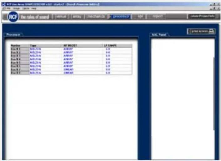
- On-axis aiming angle for each enclosure as a difference from 0° horizontal
- Various angles and throw distances calculated from the venue's dimensions
- DSP preset configuration
- SPL representation on the audience area
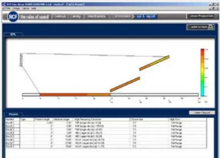
heatmap
| Name | Type | P-value | Value at single | High Frequency Conversion | Clustion size | High Freq | |---|---|---|---|---|---|---| | Box # 1 | | -0.82* | 0.75** | N/A (N/A target dts: 41.39) | 2/3 | N/A Foreign | | Box # 2 | | -0.82* | 0.75** | N/A (N/A target dts: 126.53) | 2/6 | N/A Foreign | | Box # 3 | | -1.00* | 0.80** | N/A (N/A target dts: 45.85) | 2/5 | N/A Foreign | | Box # 4 | | -1.00* | 0.80** | N/A (N/A target dts: 16.73) | 2/6 | N/A Foreign | | Box # 5 | | -10.00* | 0.80** | N/A (N/A target dts: 25.33) | 2/8 | N/A Foreign | | Box # 6 | | -10.00* | 0.80** | N/A (N/A target dts: 18.75) | 2/5 | N/A Foreign | | Box # 7 | | -27.00* | 0.80** | N/A (N/A target dts: 14.26) | 2/6 | N/A Foreign | | Box # 8 | | -35.00* | 0.80** | N/A (N/A target dts: 11.75) | 2/5 | N/A Foreign |WARNING: It is possible to display different pages only IN SEQUENCE (venue > array > mechanics > processor > spl & report, and back), in order to be sure that all pages will be shown to the user, including the one regarding mechanics.
MECHANICS PAGE
PROCESSOR PAGE
SPL & REPORT PAGE
WARNING

RCF Shape Designer works in either of two basic ways:
- AUTOMATIC MODE (default setting): The RCF Shape Designer will select the optimum enclosure splays, array aiming angle, fly-bar pick point and DSP preset configurations.
- MANUAL MODE: This provides a partial control over the array's configuration. The enclosure splays can be increased with a progression of 2° steps for each adjacent speaker, in order to maintain a spiral array configuration. Then array aiming angle, and fly-bar pick point can be entered manually by switching on Box1 + grid changeable and MANUAL H flags.

Array window: Manual splays setting
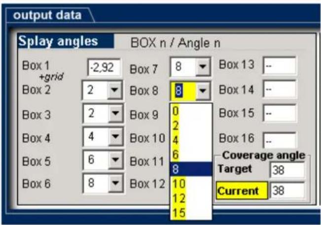
Angles manual changing
ACOUSTICAL Operating frequency range
Max SPL
Crossover point
INPUT/OUTPUT SECTION
Input signal
Input connectors
Output connectors
Input sensitivity
PROCESSOR SECTION
Protections
Limiter
Controls
AMPLIFIER Total power
Low frequencies
Cooling
Connections
CABINET Cabinet Material
Hardware
Handles
Colour
PHYSICAL Height
Width
Depth
Net Weight
Frequency Response -3 dB: 30 Hz ÷ 140 kHz
Max SPL: 135 dB
Woofer: 18", 4.0" v.c.
bal/unbal
XLR
XLR
-2 dBu / +4 dBu
Thermal, RMS
Soft limiter
Volume, EQ shape, Xover
1000 W
1000 W
Convection/forced
Powercon in/out
Baltic Birch
Rigging flyware / M20 insert
2 side
Black
511.5 mm (20.1")
700 mm (27.5")
620 mm (24.4")
48.4 kg (106.7 lbs)
www.rcf.it
HEADQUARTERS:
RCF S.p.A. Italy
tel. +39 0522 274 411
e-mail: info@rcf.it
RCF UK
tel. 0844 745 1234
Int. +44 870 626 3142
e-mail: info@rcfaudio.co.uk
RCF France
tel. +33 1 49 01 02 31
e-mail: france@rcf.it
RCF Germany
tel.+49 2203 925370
e-mail: germany@rcf.it
RCF Spain
tel. +34 91 817 42 66
e-mail: info@rcfaudio.es
RCF Belgium
tel. +32 (0) 3 - 3268104
e-mail: belgium@rcf.it
RCF USA Inc.
tel. +1 (603) 926-4604
e-mail: info@rcf-usa.com
- POWER SUPPLY FROM MAINS
- IMPORTANT NOTES
- OPERATING PRECAUTIONS
- THE HDL18-AS ACTIVE FLYABLE HIGH POWER SUBWOOFER
- The HDL18-AS features:
- The HDL18-AS input section provides:
- The HDL18-AS amplifier section features:
- REAR PANEL
- CONNECTIONS
- INSTALLATION
- MAINS SUPPLY
- HDL18-AS SUSPENDED
- THE HDL18-A FLY BAR
- ARRAY SYSTEMS DESIGN
- COMPUTER REQUIREMENTS
- INTRODUCTION
- USING RCF SHAPE DESIGNER SOFTWARE
- ENTERING VENUE DATA
- COVERAGE
- ARRAY INSTALLATION
- AUTO H SETTING - MIN TRIM HEIGHT
- AUTO H SETTING - MAX SUSPENSION POINT
- MANUAL H SETTING
- VENUE PAGE
- HEADQUARTERS:
- RCF S.p.A. Italy
- RCF UK
- RCF France
- RCF Germany
- RCF Spain
- RCF Belgium
- RCF USA Inc.
Brand : RCF
Model : HDL18-AS
Category : Loudspeaker