MXZ-8C140VAMD - Air Conditioning MITSUBISHI - Free user manual and instructions
Find the device manual for free MXZ-8C140VAMD MITSUBISHI in PDF.

| Product Type | Multi-Split Air Conditioner Outdoor Unit |
| Brand | Mitsubishi Electric |
| Model | MXZ-8C140VAMD |
| Cooling Capacity | 14.0 kW (approx. 48,000 BTU/h) |
| Heating Capacity | 16.0 kW (approx. 54,600 BTU/h) |
| Dimensions (H x W x D) | 880 x 1050 x 330 mm |
| Weight | 82 kg |
| Power Supply | 3-phase, 400V, 50Hz |
| Power Input (Cooling/Heating) | 4.5 kW / 4.8 kW |
| Refrigerant | R32 (pre-charged) |
| Max. Connectable Indoor Units | 8 |
| Compressor Type | Inverter-driven scroll compressor |
| Functions | Cooling, heating, dehumidification, fan only, auto mode, programmable timer, sleep mode |
| Noise Level (Outdoor) | 50 dB(A) (low speed) |
| Energy Efficiency (SEER/SCOP) | SEER 6.5 / SCOP 4.2 (approx.) |
| Maintenance | Clean air filters every 2 weeks; inspect coils annually; professional service every 2 years |
| Safety Features | Overcurrent protection, refrigerant leak detection, high pressure cut-off, auto restart |
| Spare Parts | Remote controller (PAR-33MAA), air filters, PCB board, fan motor, compressor |
| Repairability Index | 7.5 / 10 (serviceable by certified technician) |
| Operating Temperature Range (Cooling) | -10°C to 46°C |
| Operating Temperature Range (Heating) | -15°C to 24°C |
| Warranty | 5 years (compressor), 2 years (parts) |
| Installation Requirements | Professional installation required; clearance of 30 cm around unit |
Frequently Asked Questions - MXZ-8C140VAMD MITSUBISHI
User questions about MXZ-8C140VAMD MITSUBISHI
0 question about this device. Answer the ones you know or ask your own.
Ask a new question about this device
Download the instructions for your Air Conditioning in PDF format for free! Find your manual MXZ-8C140VAMD - MITSUBISHI and take your electronic device back in hand. On this page are published all the documents necessary for the use of your device. MXZ-8C140VAMD by MITSUBISHI.
USER MANUAL MXZ-8C140VAMD MITSUBISHI
Air-Conditioners OUTDOOR UNIT MXZ-8C140/160VAMD-A

text_image
HFC utilized R410AContents
- Safety precautions....2
- Installation diagram & parts....3
- Installation location 4
- Installing the outdoor unit 6
-
Installing the refrigerant piping 6
-
Drainage piping work....10
- Electrical work 10
- Test run.... 17
- Special Functions 18
Confirmation of parts attached
In addition to this manual, the following parts are supplied with the outdoor unit.
They are used for grounding the S terminals of transmission terminal blocks TB3, TB7.
For details refer to "7. Electrical work".
Grounding lead wire (× 2)
1. Safety precautions
Before installing the unit, make sure you read all the "Safety precautions".
▶ Please report to or take consent by the supply authority before connection to the system.
Warning:
Describes precautions that must be observed to prevent danger of injury or death to the user.
Caution:
Describes precautions that must be observed to prevent damage to the unit.
After installation work has been completed, explain the "Safety Precautions" use, and maintenance of the unit to the customer according to the information in the Operation Manual and perform the test run to ensure normal operation. Both the Installation Manual and Operation Manual must be given to the user for keeping. These manuals must be passed on to subsequent users.

Indicates a part which must be grounded.
Warning:
Carefully read the labels affixed to the main unit.
Warning:
- The unit must not be installed by the user. Ask a dealer or an authorized technician to install the unit. If the unit is installed incorrectly, water leakage, electric shock, or fire may result.
- For installation work, follow the instructions in the Installation Manual and use tools and pipe components specifically made for use with R410A refrigerant.
- The R410A refrigerant in the HFC system is pressurized 1.6 times the pressure of usual refrigerants. If pipe components not designed for R410A refrigerant are used and the unit is not installed correctly, the pipes may burst and cause damage or injuries. In addition, water leakage, electric shock, or fire may result.
- The unit must be installed according to the instructions in order to minimize the risk of damage from earthquakes, typhoons, or strong winds. An incorrectly installed unit may fall down and cause damage or injuries.
- The unit must be securely installed on a structure that can sustain its weight. If the unit is mounted on an unstable structure, it may fall down and cause damage or injuries.
- If the air conditioner is installed in a small room, measures must be taken to prevent the refrigerant concentration in the room from exceeding the safety limit in the event of refrigerant leakage. Consult a dealer regarding the appropriate measures to prevent the allowable concentration from being exceeded. Should the refrigerant leak and cause the concentration limit to be exceeded, hazards due to lack of oxygen in the room may result.
- Ventilate the room if refrigerant leaks during operation. If refrigerant comes into contact with a flame, poisonous gases will be released.
- All electric work must be performed by a qualified technician according to local regulations and the instructions given in this manual. The units must be powered by dedicated power lines and the correct voltage and circuit breakers must be used. Power lines with insufficient capacity or incorrect electrical work may result in electric shock or fire.
- Be sure to connect the power supply cords and the connecting wires for the indoor units, outdoor units, and branch boxes directly to the units (no intermediate connections).
Intermediate connections can lead to communication errors if water enters the cords or wires and causes insufficient insulation to ground or a poor electrical contact at the intermediate connection point.
(If an intermediate connection is necessary, be sure to take measures to prevent water from entering the cords and wires.)
- Use C1220 copper phosphorus, for copper and copper alloy seamless pipes, to connect the refrigerant pipes. If the pipes are not connected correctly, the unit will not be properly grounded and electric shock may result.
- Use only specified cables for wiring. The wiring connections must be made securely with no tension applied on the terminal connections. Also, never splice the cables for wiring (unless otherwise indicated in this document). Failure to observe these instructions may result in overheating or a fire.
- The terminal block cover panel of the outdoor unit must be firmly attached. If the cover panel is mounted incorrectly and dust and moisture enter the unit, electric shock or fire may result.
- When installing or relocating, or servicing the outdoor unit, use only the specified refrigerant (R410A) to change the refrigerant lines. Do not mix it with any other refrigerant and do not allow air to remain in the lines. If air is mixed with the refrigerant, then it can be the cause of abnormal high pressure in the refrigerant line, and may result in an explosion and other hazards. The use of any refrigerant other than that specified for the system will cause mechanical failure or system malfunction or unit breakdown. In the worst case, this could lead to a serious impediment to securing product safety.
- Use only accessories authorized by Mitsubishi Electric and ask a dealer or an authorized technician to install them. If accessories are incorrectly installed, water leakage, electric shock, or fire may result.
- Do not alter the unit. Consult a dealer for repairs. If alterations or repairs are not performed correctly, water leakage, electric shock, or fire may result.
- The user should never attempt to repair the unit or transfer it to another location. If the unit is installed incorrectly, water leakage, electric shock, or fire may result. If the air conditioner must be repaired or moved, ask a dealer or an authorized technician.
- After installation has been completed, check for refrigerant leaks. If refrigerant leaks into the room and comes into contact with the flame of a heater or portable cooking range, poisonous gases will be released.
1.1. Before installation
Caution:
- Do not use the unit in an unusual environment. If the air conditioner is installed in areas exposed to steam, volatile oil (including machine oil), or sulfuric gas, areas exposed to high salt content such as the seaside, or areas where the unit will be covered by snow, the performance can be significantly reduced and the internal parts can be damaged.
-
Do not install the unit where combustible gases may leak, be produced, flow, or accumulate. If combustible gas accumulates around the unit, fire or explosion may result.
-
The outdoor unit produces condensation during the heating operation. Make sure to provide drainage around the outdoor unit if such condensation is likely to cause damage.
- When installing the unit in a hospital or communications office, be prepared for noise and electronic interference. Inverters, home appliances, high-frequency medical equipment, and radio communications equipment can cause the air conditioner to malfunction or breakdown. The air conditioner may also affect medical equipment, disturbing medical care, and communications equipment, harming the screen display quality.
1.2. Before installation (relocation)
Caution:
- Be extremely careful when transporting the units. 2 or more persons are needed to handle the unit, as it weighs 20kg or more. Do not grasp the packaging bands. Wear protective gloves to remove the unit from the packaging and to move it, as you can injure your hands on the fins or the edge of other parts.
-
Be sure to safely dispose of the packaging materials. Packaging materials, such as nails and other metal or wooden parts may cause stabs or other injuries.
-
The base and attachments of the outdoor unit must be periodically checked for looseness, cracks or other damage. If such defects are left uncorrected, the unit may fall down and cause damage or injuries.
- Do not clean the air conditioner unit with water. Electric shock may result.
- Tighten all flare nuts to specification using a torque wrench. If tightened too much, the flare nut can break after an extended period and refrigerant can leak out.
1.3. Before electric work
Caution:
- Be sure to install circuit breakers. If not installed, electric shock may result.
IMPORTANT
Make sure that the current leakage breaker is one compatible with higher harmonics.
Always use a current leakage breaker that is compatible with higher harmonics as this unit is equipped with an inverter.
The use of an inadequate breaker can cause the incorrect operation of inverter.
- For the power lines, use standard cables of sufficient capacity. Otherwise, a short circuit, overheating, or fire may result.
- When installing the power lines, do not apply tension to the cables. If the connections are loosened, the cables can snap or break and overheating or fire may result.
- Be sure to ground the unit. Do not connect the ground wire to gas or water pipes, lighting rods, or telephone grounding lines. If the unit is not properly grounded, electric shock may result.
- Use circuit breakers (ground fault interrupter, isolating switch (+B fuse), and molded case circuit breaker) with the specified capacity. If the circuit breaker capacity is larger than the specified capacity, breakdown or fire may result.
1.4. Before starting the test run
Caution:
- Turn on the main power switch more than 12 hours before starting operation. Starting operation just after turning on the power switch can severely damage the internal parts. Keep the main power switch turned on during the operation season.
-
Before starting operation, check that all panels, guards and other protective parts are correctly installed. Rotating, hot, or high voltage parts can cause injuries.
-
Do not touch any switch with wet hands. Electric shock may result.
- Do not touch the refrigerant pipes with bare hands during operation. The refrigerant pipes are hot or cold depending on the condition of the flowing refrigerant. If you touch the pipes, burns or frostbite may result.
- After stopping operation, be sure to wait at least 5 minutes before turning off the main power switch. Otherwise, water leakage or breakdown may result.
1.5. Using R410A refrigerant air conditioners
Caution
- Use C1220 copper phosphorus, for copper and copper alloy seamless pipes, to connect the refrigerant pipes. Make sure the insides of the pipes are clean and do not contain any harmful contaminants such as sulfuric compounds, oxidants, debris, or dust. Use pipes with the specified thickness. (Refer to page 6) Note the following if reusing existing pipes that carried R22 refrigerant.
- Replace the existing flare nuts and flare the flared sections again.
- Do not use thin pipes. (Refer to page 6)
- Store the pipes to be used during installation Indoors and keep both ends of the pipes sealed until just before brazing. (Leave elbow joints, etc. in their packaging.) If dust, debris, or moisture enters the refrigerant lines, oil deterioration or compressor breakdown may result.
-
Use ester oil, ether oil, alkylbenzene oil (small amount) as the refrigeration oil applied to the flared sections. If mineral oil is mixed in the refrigeration oil, oil deterioration may result.
-
Do not use refrigerant other than R410A refrigerant. If another refrigerant is used, the chlorine will cause the oil to deteriorate.
- Use the following tools specifically designed for use with R410A refrigerant. The following tools are necessary to use R410A refrigerant. Contact your nearest dealer for any questions.
| Tools (for R410A) | |
| Gauge manifold Flare tool | |
| Charge hose Size adjustment gauge | |
| Gas leak detector Vacuum pump adapter | |
| Torque wrench Electronic refrigerant charging scale |
- Be sure to use the correct tools. If dust, debris, or moisture enters the refrigerant lines, refrigeration oil deterioration may result.
- Do not use a charging cylinder. If a charging cylinder is used, the composition of the refrigerant will change and the efficiency will be lowered.
2. Installation diagram & parts
text_image
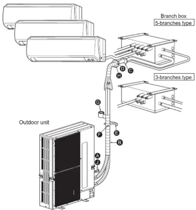
Outdoor unit Branch box 5-branches type 3-branches typeFig. 2-1
2.1. Before installation (Fig. 2-1)
This installation manual is only for the outdoor unit installation. In installing the indoor units and branch box, refer to the installation manual attached to each unit.
Any structural alterations necessary for the installation must comply with the local building code requirements.
This diagram is intended to show the configuration of accessories.
For actual installation, the outdoor unit is to be turned 180°.
Units should be installed by licensed contractor according to local code requirement.
Note:
The dimensions given along the arrows above are required to guarantee the air conditioner's performance. Install the unit in as wide a place as possible for later service or repairs.
Parts to be locally procured
| A | Branch box/outdoor unit connecting wire (3-core) | 1 |
| B | Extension pipe | 1 |
| C | Wall hole sleeve | 1 |
| D | Wall hole cover | 1 |
| E | Pipe fixing band(The quantity depends on the pipe length.) | 2 to 7 |
| F | Fixing screw for E × 20 mm (The quantity depends on the pipe length.) | 2 to 7 |
| G | Piping tape | 1 |
| H | Putty | 1 |
| I | Refrigeration oil | 1 |
| J | Power supply cord (2-core, Refer to 7.3. Wiring transmission cables) | 1 |
text_image
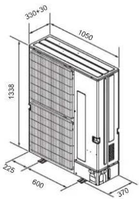
330+30 1050 1338 225 600 370Fig. 3-1
(mm)
natural_image
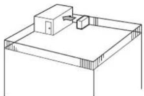
Simple line drawing of a mechanical setup with a box and housing (no text or symbols)Fig. 3-2
natural_image
Technical line drawing of an industrial server unit with labeled component A (no text or symbols beyond label)Fig. 3-3
natural_image
Technical line drawing of a modular air conditioning unit with directional arrows indicating airflow or movement (no text or symbols)Fig. 3-4
3.1. Refrigerant pipe
Refer to 5.2. Pipe length and height difference.
3.2. Choosing the outdoor unit installation location
- Avoid locations exposed to direct sunlight or other sources of heat.
- Select a location from which noise emitted by the unit will not inconvenience neighbors.
- Select a location permitting easy wiring and pipe access to the power source and indoor unit.
- Avoid locations where combustible gases may leak, be produced, flow, or accumulate.
• Note that water may drain from the unit during operation. - Select a level location that can bear the weight and vibration of the unit.
- Avoid locations where the unit can be covered by snow. In areas where heavy snow fall is anticipated, special precautions such as raising the installation location or installing a hood on the air intake must be taken to prevent the snow from blocking the air intake or blowing directly against it. This can reduce the airflow and a malfunction may result.
- Avoid locations exposed to oil, steam, or sulfuric gas.
- Use the transportation handles of the outdoor unit to transport the unit. If the unit is carried from the bottom, hands or fingers may be pinched.
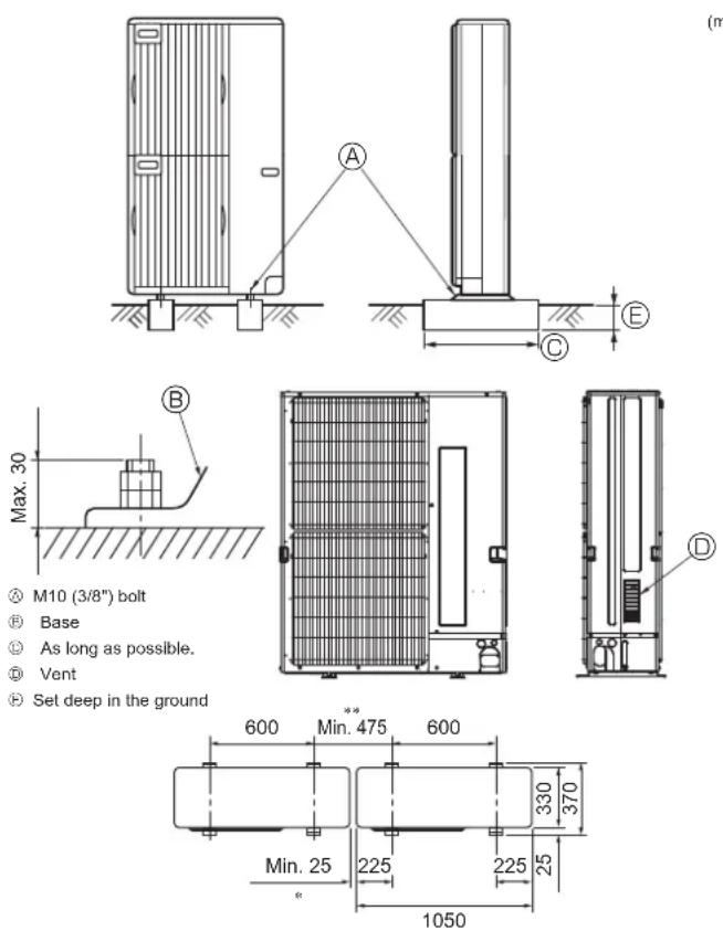
3.3. Outline dimensions (Outdoor unit) (Fig. 3-1)
3.4. Constraints on indoor unit and branch box installation
You should note that indoor units that can be connected to this outdoor unit have the following constraints.
- Indoor units with model in table 2 can be connected.
- For the number of units that can be connected, refer to Table 1 below.
- The total rated capacity (cooling) of the connected indoors units (refer to Table 2) must not exceed 130% of the outdoor unit capacity (refer to the capacity range of connected units in Table 1).*
In addition, up to 2 branch boxes can be connected.
Table 1: Number of units that can be connected and capacity range of connected units
| Outdoor unit model name | The capacity of outdoor unit | Number of units that can be connected | Capacity range of connected units |
| MXZ-8C140 14.0 kW | 2 – 8 units 4.4 – 18 | 2 kW | |
| MXZ-8C160 15.5 kW | 2 – 8 units 4.4 – 20 | 2 kW |
Table 2: Rated capacity (cooling) of the indoor units
M series, S series and P series
| Indoor unit type 22 25 35 42 50 60 71 80 100 | ||||
| Rated capacity (kW) 2.2 2.5 3.5 4.2 5 0 6.0 7.1 8 0 10.0 |
Example: MXZ-8C160
| MSZ-50 = 5.0 | + |
| MSZ-42 = 4.2 | + |
| MSZ-35 = 3.5 | + |
| SEZ-35 = 3.5 | + |
| SEZ-25 = 2.5 | + |
Combinations in which the total capacity of indoor units exceeds the capacity of the outdoor unit will reduce the cooling capacity of each indoor unit below their rated cooling capacity. Thus, combine indoor units with an outdoor unit within the outdoor unit's capacity, if possible.
3.5. Ventilation and service space
3.5.1. Windy location installation
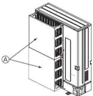
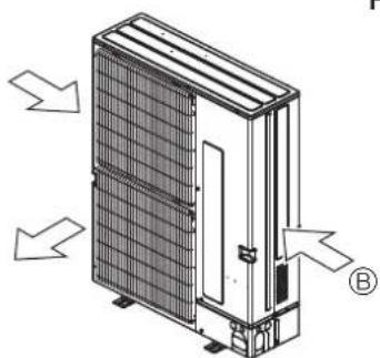
When installing the outdoor unit on a rooftop or other location unprotected from the wind, situate the air outlet of the unit so that it is not directly exposed to strong winds. Strong wind entering the air outlet may impede the normal airflow and a malfunction may result.
The following shows 3 examples of precautions against strong winds.
① Face the air outlet towards the nearest available wall about 50 cm away from the wall. (Fig. 3-2)
② Install an optional air guide if the unit is installed in a location where strong winds from a typhoon, etc. may directly enter the air outlet. (Fig. 3-3)
④ Air guide
③ Position the unit so that the air outlet blows perpendicularly to the seasonal wind direction, if possible. (Fig. 3-4)
® Wind direction
text_image
150 Max. 500 1000 300 200 200 *** 300 1000 (mm)Fig. 3-8 Fig. 3-7 Fig. 3-6 Fig
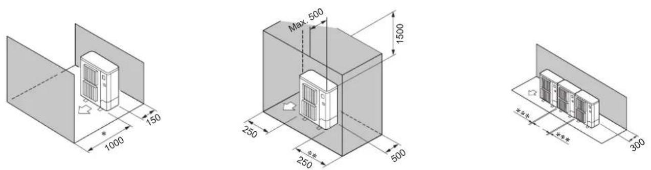
Fig. 3-9 Fig. 3-10 Fig. 3-11
text_image
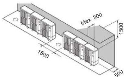
Max: 300 1500 1500 500Fig. 3-12
natural_image
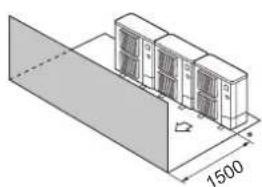
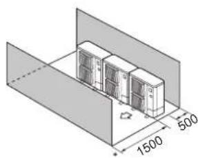
Isometric architectural diagram of a server room with a sloped roof and dimension label (1500), no text or symbols present.Fig. 3-13 Fig. 3-14
natural_image
Isometric diagram of server racks inside a storage unit, showing dimensions 1500x500x and a central control panel (no text labels or symbols)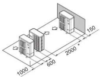
text_image
1000 600 2000 150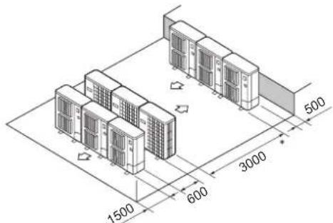
text_image
1500 600 3000 500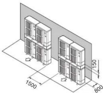
text_image
1500 150 800Fig. 3-15 Fig. 3-16 Fig. 3-17
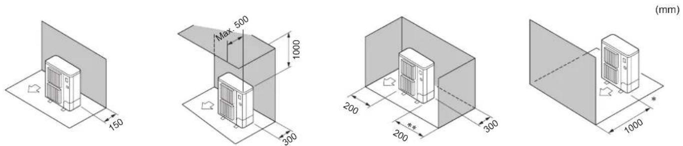
3.5.2. When installing a single outdoor unit
Minimum dimensions are as follows, except for Max., meaning Maximum dimensions, indicated.
Refer to the figures for each case.
① Obstacles at rear only (Fig. 3-5)
② Obstacles at rear and above only (Fig. 3-6)
③ Obstacles at rear and sides only (Fig. 3-7)
** To receive the DRED signals for demand control, the clearance is 350 mm or more.
④ Obstacles at front only (Fig. 3-8)
* When using the optional air outlet guides, the clearance is 500 mm or more.
⑤ Obstacles at front and rear only (Fig. 3-9)
* When using the optional air outlet guides, the clearance is 500 mm or more.
⑥ Obstacles at rear, sides, and above only (Fig. 3-10)
- Do not install the optional air outlet guides for upward airflow.
** To receive the DRED signals for demand control, the clearance is 350 mm or more.
3.5.3. When installing multiple outdoor units
Leave 25 mm space or more between the units.
*** To receive the DRED signals for demand control, the clearance is 350 mm or more.
① Obstacles at rear only (Fig. 3-11)
② Obstacles at rear and above only (Fig. 3-12)
- No more than 3 units must be installed side by side. In addition, leave space as shown.
- Do not install the optional air outlet guides for upward airflow.
③ Obstacles at front only (Fig. 3-13)
* When using the optional air outlet guides, the clearance is 1000 mm or more.
④ Obstacles at front and rear only (Fig. 3-14)
* When using the optional air outlet guides, the clearance is 1000 mm or more.
⑤ Single parallel unit arrangement (Fig. 3-15)
* When using the optional air outlet guides installed for upward airflow, the clearance is 1000 mm or more.
⑥ Multiple parallel unit arrangement (Fig. 3-16)
* When using the optional air outlet guides installed for upward airflow, the clearance is 1500 mm or more.
⑦ Stacked unit arrangement (Fig. 3-17)
• The units can be stacked up to 2 units high.
- No more than 2 stacked units must be installed side by side. In addition, leave space as shown.

4. Installing the outdoor unit
(mm)
Fig. 4-1
5. Installing the refrigerant piping
flowchart
graph TD
    A["Outdoor unit"] --> B["Branch box"]
    B --> C["Indoor unit"]
    C --> D["The first joint"]
    D --> E["L"]
    E --> F["b1"]
    F --> G["c1"]
    G --> H["h1"]
    H --> I["a1"]
    I --> J["c3"]
    J --> K["h3"]
    K --> L["a2"]
    L --> M["c4"]
    M --> N["a3"]
    N --> O["c5"]
    O --> P["a4"]
    P --> Q["c6"]
    Q --> R["a5"]
    R --> S["c7"]
    S --> T["a6"]
    T --> U["c8"]
    U --> V["I"]
    V --> W["b2"]
Fig. 5-1
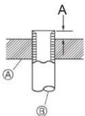
- Be sure to install the unit in a sturdy, level surface to prevent rattling noises during operation. (Fig. 4-1)
| Foundation bolt M10 | |
| Thickness of concrete 120 mm | |
| Length of bolt 70 mm | |
| Weight-bearing capacity 320 kg |
- Make sure that the length of the foundation bolt is within 30 mm of the bottom surface of the base.
- Secure the base of the unit firmly with four-M10 foundation bolts in sturdy locations.
Installing the outdoor unit
- Do not block the vent. If the vent is blocked, operation will be hindered and breakdown may result.
- In addition to the unit base, use the installation holes on the back of the unit to attach wires, etc., if necessary to install the unit. Use self-tapping screws ( 5 × 15 mm or less) and install on site.
Warning:
- The unit must be securely installed on a structure that can sustain its weight.
If the unit is mounted on an unstable structure, it may fall down and cause damage or injuries. - The unit must be installed according to the instructions in order to minimize the risk of damage from earthquakes, typhoons, or strong winds. An incorrectly installed unit may fall down and cause damage or injuries.
Caution:
- Install the unit on a rigid structure to prevent excessive operation sound or vibration.
* To receive the DRED signals for demand control, the clearance is 350 mm or more.
** To receive the DRED signals for demand control, the clearance is 800 mm or more.
5.1. Precautions for devices that use R410A refrigerant
- Refer to page 3 for precautions not included below on using air conditioners with R410A refrigerant.
- Use ester oil, ether oil, alkylbenzene oil (small amount) as the refrigeration oil applied to the flared sections.
- Use C1220 copper phosphorus, for copper and copper alloy seamless pipes, to connect the refrigerant pipes. Use refrigerant pipes with the thicknesses specified in the table to the below. Make sure the insides of the pipes are clean and do not contain any harmful contaminants such as sulfuric compounds, oxidants, debris, or dust.
Warning:
When installing or relocating, or servicing the outdoor unit, use only the specified refrigerant (R410A) to charge the refrigerant lines. Do not mix it with any other refrigerant and do not allow air to remain in the lines.
If air is mixed with the refrigerant, then it can be the cause of abnormal high pressure in the refrigerant line, and may result in an explosion and other hazards. The use of any refrigerant other than that specified for the system will cause mechanical failure or system malfunction or unit breakdown. In the worst case, this could lead to a serious impediment to securing product safety.
| ø6.35 mm, ø9.52 mm, ø12.7 mm Thickness 0.8 mm | |
| ø15.88 mm Thickness 1.0 mm | |
- Do not use pipes thinner than those specified above.
- The thicknesses listed in the table above are based on Japanese standards. Use pipes with a maximum working pressure of 4.15 MPa or higher according to local standards.
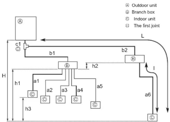
| Permissible length (one-way) | Total piping length | c1 + b1 + b2 + a1 + a2 + a3 + a4 + a5 + a6 ≤ 150 m |
| Farthest piping length (L) | c1 + b2 + a6 ≤ 80 m (b2 ≤ 55 m, a6 ≤ 25 m) | |
| Piping length between outdoor unit and branch boxes | c1 + b1 + b2 ≤ 55 m | |
| Farthest branch box from the first joint (b2) | b2 ≤ 30 m | |
| Farthest piping length after branch box (l) | a6 ≤ 25 m | |
| Total piping length between branch boxes and indoor units | a1 + a2 + a3 + a4 + a5 + a6 ≤ 95 m | |
| Permissible height difference (one-way) | In indoor/outdoor section (H) *1 | H ≤ 30 m (In case of outdoor unit is set higher than indoor unit) |
| H ≤ 20 m (In case of outdoor unit is set lower than indoor unit) | ||
| In branch box/indoor unit section (h1) | h1 + h2 ≤ 15 m | |
| In each branch unit (h2) | h2 ≤ 15 m | |
| In each indoor unit (h3) | h3 ≤ 12 m | |
| Number of bends | | c1 + b1 + a1 |, | c1 + b1 + a2 |, | c1 + b1 + a3 |, | c1 + b1 + a4 |, | c1 + b1 + a5 |, | c1 + b2 + a6 | ≤ 15 | |
*1 Branch box should be placed within the level between the outdoor unit and indoor units.
5.2. Pipe length and height difference (Fig. 5-1)
Flared connections
- This unit has flared connections on each indoor unit and branch box and outdoor unit sides.
5.3. Additional refrigerant charge
Additional refrigerant charge
- The necessity of additional refrigerant is determined according to the total piping length (c1+b1+b2+a1+a2+a3+a4+a5+a6) and the total capacity of indoor units. Refer to the chart to the right.
- If additional refrigerant is necessary, charge the unit with additional refrigerant according to the permitted pipe length in the chart to the right.
In addition, in order to carry out service, enter the size and length of each liquid pipe and additional refrigerant charge amounts in the spaces provided on the "Refrigerant amount" plate on the outdoor unit.
Calculation of additional refrigerant charge
- Calculate the additional charge using the liquid pipe size and length of the extended piping and total capacity of connected indoor units.
- Calculate the additional refrigerant charge using the procedure shown to the right, and charge with the additional refrigerant.
-
For amounts less than 0.1 kg, round up the calculated additional refrigerant charge.
(For example, if the calculated charge is 2.81 kg, round up the charge to 2.9 kg.) -
Remove the valve cover of the outdoor unit, then connect the pipe.
- Refrigerant pipes are used to connect the branch box and outdoor unit.
Necessity of additional charge
| Total capacity of indoor units | Total piping length | ||
| 0 m – 5 m | 6 m – 15 m | 16 m – | |
| - 16.0 kW | Not necessary | Not necessary | Necessary |
| 16.1 kW – 20.2 kW * | Not necessary | Necessary | Necessary |
* For MXZ-8C140, the capacity is 16.1 - 18.2 kW.
Calculation of refrigerant charge
| Pipe size Liquid pipeø6.35(m) × 19.0 (g/m) | + | Pipe size Liquid pipeø9.52(m) × 50.0 (g/m) | -0.2 kg |
* For amounts less than 0 kg, use 0 kg.
Included refrigerant amount when shipped from the factory
| Included refrigerant amount |
| 8.0 kg |
| Outdoor model : MXZ-8C160VAMD | c1 + b1 : ø9.52 | 30 m | |
| Indoor | 1: model 71 | a1 : ø9.52 | 15 m |
| 2: model 42 | a2 : ø6.35 | 10 m | |
| 3: model 25 | a3 : ø6.35 | 10 m | |
| 4: model 25 | a4 : ø6.35 | 20 m | |
The total length of each liquid line is as follows:
∅9.52 : c1 + b1 + a1 = 30 + 15 = 45 m
Additional refrigerant charge
$$ 4 0 \times \frac {1 9 . 0}{1 0 0 0} + 4 5 \times \frac {5 0 . 0}{1 0 0 0} - 0. 2 = 2. 9 (\text { rounded up }) $$
■ In case of using 1-branch box
Flare connection employed. (No. brazing)
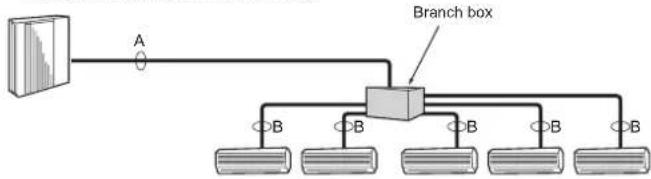
flowchart
graph TD
    A["Client Device"] -->|A| B["Branch Box"]
    B --> C1["Client 1"]
    B --> C2["Client 2"]
    B --> C3["Client 3"]
    B --> C4["Client 4"]
    B --> C5["Client 5"]
■ In case of using 2-branch boxes
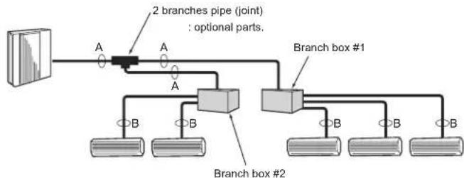
flowchart
graph TD
    A["Main Component"] --> B["Joint Junction"]
    B --> C["Branch Box #1"]
    B --> D["Branch Box #2"]
    C --> E["Output 1"]
    C --> F["Output 2"]
    D --> G["Output 3"]
    D --> H["Output 4"]
    D --> I["Output 5"]
Fig. 5-2
(1) Valve size for outdoor unit
| For liquid 9.52 mm | |
| For gas 15.88 mm |
(2) Valve size for branch box
| ☒ UNIT | Liquid pipe ø6.35 mm | |
| Gas pipe ø9.52 mm | ||
| ☒ UNIT | Liquid pipe ø6.35 mm | |
| Gas pipe ø9.52 mm | ||
| ☒ UNIT | Liquid pipe ø6.35 mm | |
| Gas pipe ø9.52 mm | ||
| ☒ UNIT | Liquid pipe ø6.35 mm | |
| Gas pipe ø9.52 mm | ||
| ☒ UNIT | Liquid pipe ø6.35 mm | |
| ☒ UNIT | Gas pipe ø12.7 mm |
* 3-branch type : only A, B, C unit
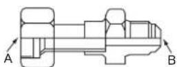
Fig. 5-3
Conversion formula
| 1/4 F | 6.35 |
| 3/8 F | 9.52 |
| 1/2 F | 12.7 |
| 5/8 F | 15.88 |
| 3/4 F | 19.05 |
5.4. Selecting pipe size (Fig. 5-2)
Conversion formula
| A | B | |
| Liquid ø9.52 mm | The piping connection size differs according to the type and capacity of indoor units. Match the piping connection size of branch box with indoor unit.If the piping connection size of branch box does not match the piping connection size of indoor unit, use optional different-diameter (deformed) joints to the branch box side. (Connect deformed joint directly to the branch box side.) | |
| Gas ø15.88 mm |
Different-diameter joint (optional parts) (Fig. 5-3)
| Model name | Connected pipes diameter | Diameter A Diameter B | |
| mm mm | mm | ||
| MAC-A454JP | 9.52 12.7 | 9.52 | 12.7 |
| MAC-A455JP | 12.7 9.52 | 12.7 | 9.52 |
| MAC-A456JP | 12.7 15.88 | 12.7 | 15.88 |
| PAC-493PI | 6.35 9.52 | 6.35 | 9.52 |
| PAC-SG76RJ-E | 9.52 15.88 | 9.52 | 15.88 |
Piping preparation
① Table below shows the specifications of pipes commercially available.
| Outside diameter Insulation thickness | Insulation material | |
| mm | mm | |
| 6.35 | 8 | Heat resisting foam plastic 0.045 specific gravity |
| 9.52 | 8 | |
| 12.7 | 8 | |
| 15.88 | 8 | |
② Ensure that the 2 refrigerant pipes are insulated to prevent condensation.
① Refrigerant pipe bending radius must be 100 mm or more.
Caution
Be sure to use the insulation of specified thickness. Excessive thickness may cause incorrect installation of the indoor unit and branch box, and lack of thickness may cause dew drippage.
2-branch pipe (Joint) : Optional parts (According to the connection method, you can choose the favorite one.
| Model name | Connection method |
| MSDD-50AR-E | flare |
| MSDD-50BR-E | brazing |
■ Installation procedure (2 branches pipe (Joint))
Refer to the installation manuals of MSDD-50AR-E and MSDD-50BR-E.
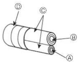
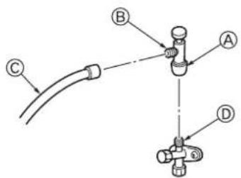
text_image
D C B AⒶ Liquid pipe
⑭ Gas pipe
© Insulation
© Taping
Fig. 5-4
text_image
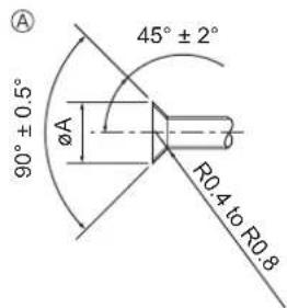
A 90° ± 0.5° ØA 45° ± 2° R0.4 to R0.8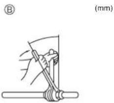
text_image
(mm)Ⓐ Flare cutting dimensions
⑧ Flare nut tightening torque
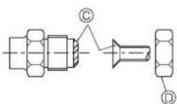
Fig. 5-5
Ⓐ (Fig. 5-5)
| Copper pipe O.D. (mm) | Flare dimensionsøA dimensions (mm) |
| ø6.35 | 8.7 - 9.1 |
| ø9.52 | 12.8 - 13.2 |
| ø12.7 | 16.2 - 16.6 |
| ø15.88 | 19.3 - 19.7 |
| Copper pipe O.D. (mm) | Flare nut O.D. (mm) | Tightening torque (N·m)* |
| ø6.35 | 17 | 14 - 18 |
| ø6.35 | 22 | 34 - 42 |
| ø9.52 | 22 | 34 - 42 |
| ø9.52 | 26 | 49 - 61 |
| ø12.7 | 26 | 49 - 61 |
| ø12.7 | 29 | 68 - 82 |
| ø15.88 | 29 | 68 - 82 |
| ø15.88 | 36 | 100 - 120 |
* 1 N·m=10 kgf·cm
Ⓐ Die
Ⓑ Copper pipe
Fig. 5-6
Warning:
When pumping down the refrigerant, stop the compressor before disconnecting the refrigerant pipes. The compressor may burst and cause injury if any foreign substance, such as air, enters the system.
5.5. Connecting pipes (Fig. 5-4) (Fig. 5-5)
- Conduct sufficient anti-condensation and insulation work to prevent water dripping from the refrigerant piping. (liquid pipe/gas pipe)
- Increase insulation depending on the environment where the refrigerant piping is installed, or condensation may occur on the surface of the insulation material. (Insulation material Heat-resistant temperature: 120 °C, Thickness: 15 mm or more)
When the refrigerant piping is used in locations subject to high temperature and humidity such as in the attic, further addition of insulation may be required.
- To insulate the refrigerant piping, apply heat-resistant polyethylene foam between the indoor unit and insulation material as well as to the net between the insulation material filling all gaps.
(Condensation forming on the piping may result in condensation in the room or burns when contacting the piping.) - The indoor parts of the drain pipe should be wrapped with polyethylene foam insulation materials (specific gravity of 0.03, thickness of 9 mm or more).
[Fig. 5-5]
- Apply thin layer of refrigerant oil to pipe and joint seating surface before tightening flare nut. Ⓐ
- Use 2 wrenches to tighten piping connections. Ⓑ
- Use leak detector or soapy water to check for gas leaks after connections are completed.
- Apply refrigerating machine oil over the entire flare seat surface. ©
- Use the flare nuts as follows.
Warning:
When installing the unit, securely connect the refrigerant pipes before starting the compressor.
■ Pipe size (Outdoor unit-Branch box)
| Pipe size(ømm) | Liquid | 9.52 |
| Gas | 15.88 |
| The lineup of a connectable indoor unit depends on a district/areas/country. |
■ Pipe size (Branch box-Indoor unit) *Case of M series or S series Indoor unit
| Indoor unit type 22 25 35 42 50 60 71 80 | |||||||||
| Pipe size (ømm) | Liquid | ø6.35 | ø6.35 | ø6.35 | ø6.35 | ø6.35 | ø6.35 | ø9.52 | ø9.52 |
| Gas | ø9.52 | ø9.52 | ø9.52 | ø9.52 | ø12.7 | ø15.88 | ø15.88 | ø15.88 | |
■ Pipe size (Branch box-Indoor unit) *Case of P series Indoor unit
| Indoor unit type | 50 | 60 | 71 | 100 | |
| Pipe size(ømm) | Liquid | ø6.35 | ø9.52 | ø9.52 | ø9.52 |
| Gas | ø12.7 | ø15.88 | ø15.88 | ø15.88 | |
- When bending the pipes, be careful not to break them. Bend radius of 100 mm to 150 mm are sufficient.
- Make sure the pipes do not contact the compressor. Abnormal noise or vibration may result.
① Pipes must be connected starting from the indoor unit. Flare nuts must be tightened with a torque wrench.
② Flare the liquid pipes and gas pipes and apply a thin layer of refrigeration oil (Applied on site). - When usual pipe sealing is used, refer to Table 2 for flaring of R410A refrigerant pipes.
The size adjustment gauge can be used to confirm A measurements.
Caution:
- Be sure to wrap insulation around the piping. Direct contact with the bare piping may result in burns or frostbite.
Table 2 (Fig. 5-6)
(mm)
| Copper pipe O.D. | A | |
| Flare tool for R410A | Flare tool for R22·R407C | |
| Clutch type | ||
| ø6.35 | 0 - 0.5 | 1.0 - 1.5 |
| ø9.52 | 0 - 0.5 | 1.0 - 1.5 |
| ø12.7 | 0 - 0.5 | 1.0 - 1.5 |
| ø15.88 | 0 - 0.5 | 1.0 - 1.5 |
text_image
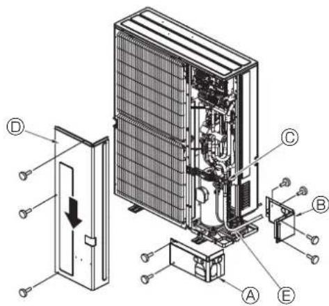
Technical diagram of an air conditioning unit with labeled components A through E, showing internal structure and component assembly.④ Front piping cover
⑧ Piping cover
© Stop valve
① Service panel
Bend radius : 100 mm - 150 mm
Fig. 5-7
text_image
(1) A B C D E F G HFig. 5-8
flowchart
graph TD
    A["Component ①"] --> B["Assembly"]
    C["Component ②"] --> D["Assembly"]
    E["Component ③"] --> F["Assembly"]
    G["Component ④"] --> H["Assembly"]
    I["Component ⑤"] --> J["Assembly"]
    K["Component ⑥"] --> L["Assembly"]
Fig. 5-9
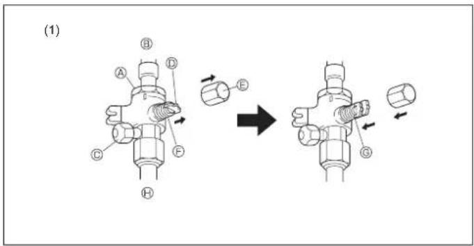
⑧ Valve ⑨ Completely closed
⑧ Unit side ⑨ Completely open
© Service port ① Refrigerant piping side (On-site installation)
© Handle ① Direction the refrigerant flows in
© Cap ⚙ Wrench hole
5.6. Refrigerant piping (Fig. 5-7)
Remove the service panel Ⓓ (3 screws) and the front piping cover Ⓐ (2 screws) and rear piping cover Ⓑ (4 screws).
① Perform refrigerant piping connections for the indoor/outdoor unit when the outdoor unit's stop valve is completely closed.
② Vacuum-purge air from the indoor unit and the connection piping.
Evacuation
Evacuate with the valve of the outdoor unit closed and evacuate both the connection piping and the indoor unit from the service port provided on the valve of the outdoor unit using a vacuum pump. (Always evacuate from the service port of both liquid pipe and gas pipe.) After the vacuum reaches 650 Pa [abs], continue evacuation for at least one hour or more. Then, stop the vacuum pump and leave it for 1 hour. Ensure the degree of vacuum has not increased. (If the degree of vacuum increase is larger than 130 Pa, water might have entered. Apply pressure to dry nitrogen gas up to 0.05 MPa and vacuum again.) Finally, seal in with the liquid refrigerant through the liquid pipe, and adjust the gas piping to obtain an appropriate amount of the refrigerant during operation.
* Never perform air purging using refrigerant.
③ After connecting the refrigerant pipes, check the connected pipes and the indoor unit for gas leaks. (Refer to 5.8 Refrigerant pipe airtight testing method)
④ Vacuumize the refrigerant lines through the service port of the liquid and gas stop valves. And then open the stop valves completely (for both the liquid and gas stop valves). This will completely connect the refrigerant lines of the indoor and outdoor units.
- If the stop valves are left closed and the unit is operated, the compressor and control valves will be damaged.
- Use a leak detector or soapy water to check for gas leaks at the pipe connection sections of the outdoor unit.
- Do not use the refrigerant from the unit to purge air from the refrigerant lines.
• After the valve work is completed, tighten the valve caps to the correct torque: 20 to 25 N·m (200 to 250 kgf·cm).
Failure to replace and tighten the caps may result in refrigerant leakage. In addition, do not damage the insides of the valve caps as they act as a seal to prevent refrigerant leakage.
⑤ Use sealant to seal the ends of the thermal insulation around the pipe connection sections to prevent water from entering the thermal insulation.
Refrigerant pipes are protectively wrapped
- The pipes can be protectively wrapped up to a diameter of 90mm before or after connecting the pipes. Cut out the knockout in the pipe cover following the groove and wrap the pipes.
Pipe inlet gap - Use putty or sealant to seal the pipe inlet around the pipes so that no gaps remain. (If the gaps are not closed, noise may be emitted or water and dust will enter the unit and breakdown may result.)
5.7. Caution for piping connection/valve operation
- Conduct piping connection and valve operation accurately by following the figure below.
- Apply sealer along the insulator to prevent water entering the insulator covering the refrigerant pipe joints.
- After evacuation and refrigerant charge, ensure that the handle is fully open. If operating with the valve closed, abnormal pressure will be imparted to the high- or low-pressure side of the refrigerant circuit, giving damage to the compressor, etc.
- Determine the amount of additional refrigerant charge (refer "5.3. Additional refrigerant charge"), and charge refrigerant additionally through the service port after completing piping connection work.
- After completing work, tighten the service port (12 - 15 N·m) and cap (20 - 25 N·m) securely to prevent gas leak.
*1 N·m ≈10 kgf·cm
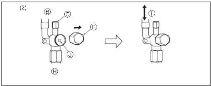
Method of completely opening the stop valve
The stop valve opening method varies according to the outdoor unit model. Use the appropriate method to open the stop valves.
(1) Gas side (Fig. 5-8)
① Remove the cap, pull the handle toward you and rotate 1/4 turn in a counterclockwise direction to open.
② Make sure that the stop valve is open completely, push in the handle and rotate the cap back to its original position.
(2) Liquid side (Fig. 5-9)
① Remove the cap and turn the valve rod counterclockwise as far as it will go with the use of a 4 mm hexagonal wrench. Stop turning when it hits the stopper.
② Make sure that the stop valve is open completely and rotate the cap back to its original position.

text_image
A E F G H I K LO B HI C DFig. 5-10
text_image
Technical diagram showing labeled components A, B, C, and D connected to a pipe or connector with dashed lines indicating alignment or connection.* The figure to the left is an example only. The stop valve shape, service port position, etc., may vary according to the model.
* Turn section Ⓧ only.
(Do not further tighten sections Ⓧ and Ⓞ together.)
© Charge hose
© Service port
Fig. 5-11
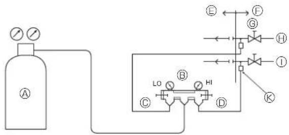
5.8. Refrigerant pipe airtight testing method.
Airtight test (Fig. 5-10)
Airtight test should be made by pressurizing nitrogen gas. For the test method, refer to the following figure.
(1) Connecting the testing tool. Make a test with the stop valve closed. Be also sure to pressurize both liquid or high-pressure pipe and gas or low pressure pipe.
(2) Do not add pressure to the specified pressure all at once; add pressure little by little.
① Pressurize to 0.5 MPa, wait 5 minutes, and make sure the pressure does not decrease.
② Pressurize to 1.5 MPa, wait 5 minutes, and make sure the pressure does not decrease.
③ Pressurize to 4.15 MPa and measure the surrounding temperature and refrigerant pressure.
(3) If the specified pressure holds for about one day and does not decrease, the pipes have passed the test and there are no leaks.
- If the surrounding temperature changes by 1^ , the pressure will change by about 0.01 MPa. Make the necessary corrections.
(4) If the pressure decreases in steps (2) or (3), there is a gas leak. Look for the source of the gas leak.
Ⓐ Nitrogen gas
⑤ Outdoor unit
© System analyzer
© Stop valve
© Lo-knob
⑧ Liquid pipe or high-pressure pipe
© Hi-knob
① Gas pipe or low-pressure pipe
⑤ To branch box
© Service port
Precautions when using the charge valve (Fig. 5-11)
Do not tighten the service port too much when installing it, otherwise, the valve core could be deformed and become loose, causing a gas leak.
After positioning section ② in the desired direction, turn section ⑧ only and tighten it. Do not further tighten sections ⑨ and ⑩ together after tightening section ⑪.
Warning:
- When installing the unit, securely connect the refrigerant pipes before starting the compressor.
6. Drainage piping work
Outdoor unit drainage pipe connection
When drain piping is necessary, use the drain socket or the drain pan (option).
| Drain socket PAC-SG61DS-E | |
| Drain pan PAC-SH97DP-E |
7. Electrical work
7.1. Caution
① Follow ordinance of your governmental organization for technical standard related to electrical equipment, wiring regulations and guidance of each electric power company.
② Wiring for control (hereinafter referred to as transmission line) shall be (5 cm or more) apart from power source wiring so that it is not influenced by electric noise from power source wiring. (Do not insert transmission line and power source wire in the same conduit.)
③ Be sure to provide designated grounding work to outdoor unit.
④ Give some allowance to wiring for electrical part box of indoor and outdoor units, because the box is sometimes removed at the time of service work.
⑤ Never connect the main power source to terminal block of transmission line. If connected, electrical parts will be burnt out.
⑥ Use 2-core shield cable for transmission line. If transmission lines of different systems are wired with the same multiplecore cable, the resultant poor transmitting and receiving will cause erroneous operations.
⑦ Only the transmission line specified should be connected to the terminal block for outdoor unit transmission.
(Transmission line to be connected with indoor unit: Terminal block TB3 for transmission line, Other: Terminal block TB7 for centralized control) Erroneous connection does not allow the system to operate.
③ In case to connect with the upper class controller or to conduct group operation in different refrigerant systems, the control line for transmission is required between the outdoor units each other.
Connect this control line between the terminal blocks for centralized control. (2-wire line with no polarity)
When conducting group operation in different refrigerant systems without connecting to the upper class controller, replace the insertion of the short circuit connector from CN41 of one outdoor unit to CN40.
⑨ Before turning outdoor unit on, be sure to turn the indoor units and the branch boxes.
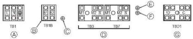
text_image
TB1 A B TB1B C TB3 TB7 D E F TBD1 GⒶ Power source
⑧ Power supply for branch box
© Screw on the electrical component box
⑦ Transmission line
© Screw on the electrical component box
① Screw on the electrical component box
© DRED signal input
Fig. 7-1
7.2. Control box and connecting position of wiring (Fig. 7-1)
- Connect the branch box transmission line to transmission terminal block (TB3), or connect the wiring between outdoor units or the wiring with the centralized control system to the centralized control terminal block (TB7). When using shielded wiring, connect shield ground of the branch box transmission line to the screw (© or F) and connect shield ground of the line between outdoor units and the central control system transmission line to the shield (S) terminal of the centralized control terminal block (TB7) shield (S) terminal. In addition, in the case of outdoor units whose power supply connector CN41 has been replaced by CN40, the shield terminal (S) of terminal block (TB7) of the centralized control system should also be connected to the screw (© or F) using attached lead wire.
- Fix power source wiring to terminal box by using buffer bushing for tensile force (PG connection or the like).
- The terminal bed (TB1B) is for supplying power to the branch box (230 V, max 6A).
- The terminal bed (TBD1) is for the input of the DRED signals (DC 12 V, 1 mA).
Caution:
Never connect the transmission line for the branch box or the central control system transmission line to this terminal bed (TB1B). If the transmission lines are connected, the indoor unit terminal block, branch box terminal block or centralized control terminal block could be damaged.
7.3. Wiring transmission cables
① Types of control cables
-
Wiring transmission cables
-
Types of transmission cables: Shielding wire CVVS or CPEVS or MVVS
• Cable diameter: More than 1.25 mm²
• Maximum wiring length: Within 200 m -
M-NET Remote control cables
| Kind of remote control cable Shielding wire (2-core) CVVS, CPEVS or MVVS. | |
| Cable diameter 0.5 to 1.25 mm ^2 | |
| Remarks | When 10 m is exceeded, use cable with the same specifications as transmission line wiring. |
* Connected with simple remote controller.
- MA Remote control cables
| Kind of remote control cable | Sheathed 2-core cable (unshielded) CVV |
| Cable diameter | 0.3 to 1.25 mm ^2 |
| Remarks | Within 200 m |
* Connected with simple remote controller.
② Wiring examples
- Controller name, symbol and allowable number of controllers.
| Name | Symbol | Allowable number of controllers | |
| Outdoor unit controller OC - | |||
| Indoor unit controller | IC | MXZ-8C140 | 2 to 8 units per 1 OC |
| MXZ-8C160 | 2 to 8 units per 1 OC | ||
| Remote controller | RC | MA | Maximum of 2 per group |
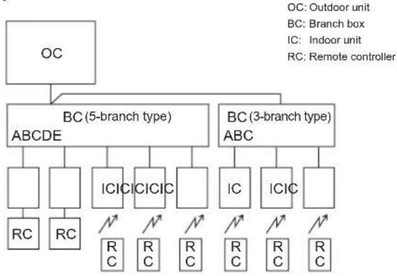
[1] Basic systems
flowchart
graph TD
    A["OC"] --> B["BC (5-branch type)"]
    A --> C["BC (3-branch type)"]
    B --> D["ABCDE"]
    B --> E[ICICICICICICICICICICICICICICICICICICICICICICICICICICICICICICICICICICICICICICICICICICICICICICICICICICICICICICICICICICICICICICICICICICICICICICICICICICICICICICICICICICICICICICICICICICICICICICICICICICICICic
    RRC
    RC
    NC
    NC
    NC
    NC
    NC
    NC
    NC
    NC
    NC
    NC
    NC
    NC
    NC
    NC
    NC
    NC
    NC
    NC
    NC
    NC
    NC
    NC
    NC
    NC
    NC
    NC
    NC
    NC
    NC
    NC
    NC
    NC
    NC
    NC

    B --> D
    B --> E
    C --> E
    C --> F
    C --> G
    C --> H
    C --> I
    C --> J
    C --> K
    C --> L
    C --> M
    C --> N
    C --> O
    C --> P
    C --> Q
    C --> R
    C --> S
    C --> T
    C --> U
    C --> V
    C --> W
    C --> X
    C --> Y
    C --> Z
    C --> AA
    C --> AB
    C --> AC
    C --> AD
    C --> AE
    C --> AF
    C --> AG
    C --> AH
    C --> AI
    C --> AJ
    C --> AK
    C --> AL
    C --> AM
    C --> AN
    C --> AO
    C --> AP
    C --> AQ
    C --> AR
    C --> AS
    C --> AT
    C --> AU
    C --> AV
    C --> AW
flowchart
graph TD
    A["OC"] --> B["BC (5-branch type)"]
    A --> C["BC (3-branch type)"]
    B --> D["ABCDE"]
    B --> E["ABC"]
    D --> F["IC"]
    D --> G["ICIC"]
    F --> H["RC"]
    G --> I["RC"]
    E --> J[" "]
    E --> K[" "]
    K --> L["RC"]
    E --> M[" "]
    E --> N[" "]
    M --> O["RC"]
    N --> P["RC"]
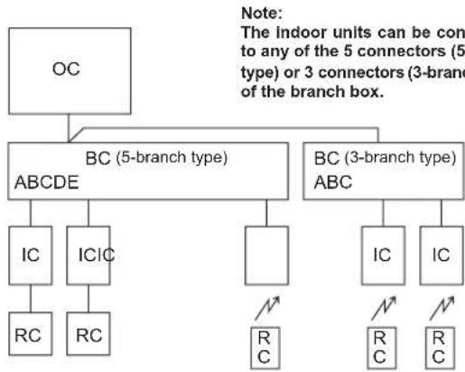
[2] Standard systems
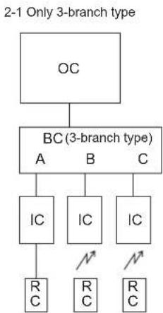
flowchart
graph TD
    A["OC"] --> B["BC (3-branch type)"]
    B --> C["IC"]
    B --> D["IC"]
    B --> E["IC"]
    C --> F["R C"]
    D --> G["R C"]
    E --> H["R C"]
2-2 Only 5-branch type
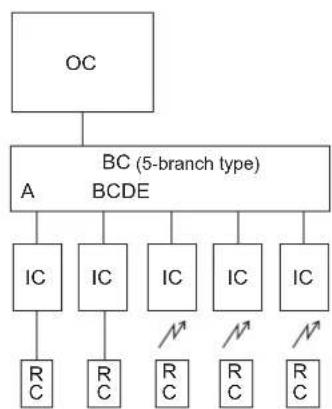
flowchart
graph TD
    OC["OC"] --> BC["BC (5-branch type)"]
    BC --> A["A"]
    BC --> BDE["BCDE"]
    A --> IC1["IC"]
    A --> IC2["IC"]
    A --> IC3["IC"]
    A --> IC4["IC"]
    A --> IC5["IC"]
    IC1 --> RC1["R_C"]
    IC2 --> RC2["R_C"]
    IC3 --> RC3["R_C"]
    IC4 --> RC4["R_C"]
    IC5 --> RC5["R_C"]
2-3 2-branch boxes (3-branch type)
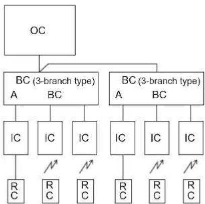
flowchart
graph TD
    OC["OC"] --> BC1["BC (3-branch type)"]
    BC1 --> A1["A"]
    BC1 --> B1["BC"]
    BC2["BC (3-branch type)"] --> A2["A"]
    BC2 --> B2["BC"]
    BC3["BC (3-branch type)"] --> A3["A"]
    BC3 --> B3["BC"]
    BC4["BC (3-branch type)"] --> A4["A"]
    BC4 --> B4["BC"]
    BC5["BC (3-branch type)"] --> A5["A"]
    BC5 --> B5["BC"]
    BC6["BC (3-branch type)"] --> A6["A"]
    BC6 --> B6["BC"]
    BC7["BC (3-branch type)"] --> A7["A"]
    BC7 --> B7["BC"]
    BC8["BC (3-branch type)"] --> A8["A"]
    BC8 --> B8["BC"]
    BC9["BC (3-branch type)"] --> A9["A"]
    BC9 --> B9["BC"]
    BC10["BC (3-branch type)"] --> A10["A"]
    BC10 --> B10["BC"]
    BC11["BC (3-branch type)"] --> A11["A"]
    BC11 --> B11["BC"]
    BC12["BC (3-branch type)"] --> A12["A"]
    BC12 --> B12["BC"]
    BC13["BC (3-branch type)"] --> A13["A"]
    BC13 --> B13["BC"]
    BC14["BC (3-branch type)"] --> A14["A"]
    BC14 --> B14["BC"]
    BC15["BC (3-branch type)"] --> A15["A"]
    BC15 --> B15["BC"]
    BC16["BC (3-branch type)"] --> A16["A"]
    BC16 --> B16["BC"]
    BC17["BC (3-branch type)"] --> A17["A"]
    BC17 --> B17["BC"]
    BC18["BC (3-branch type)"] --> A18["A"]
    BC18 --> B18["BC"]
    BC19["BC (3-branch type)"] --> A19["A"]
    BC19 --> B19["BC"]
2-4. 2 branch boxes (5-branch type, maximum 8 indoor units)
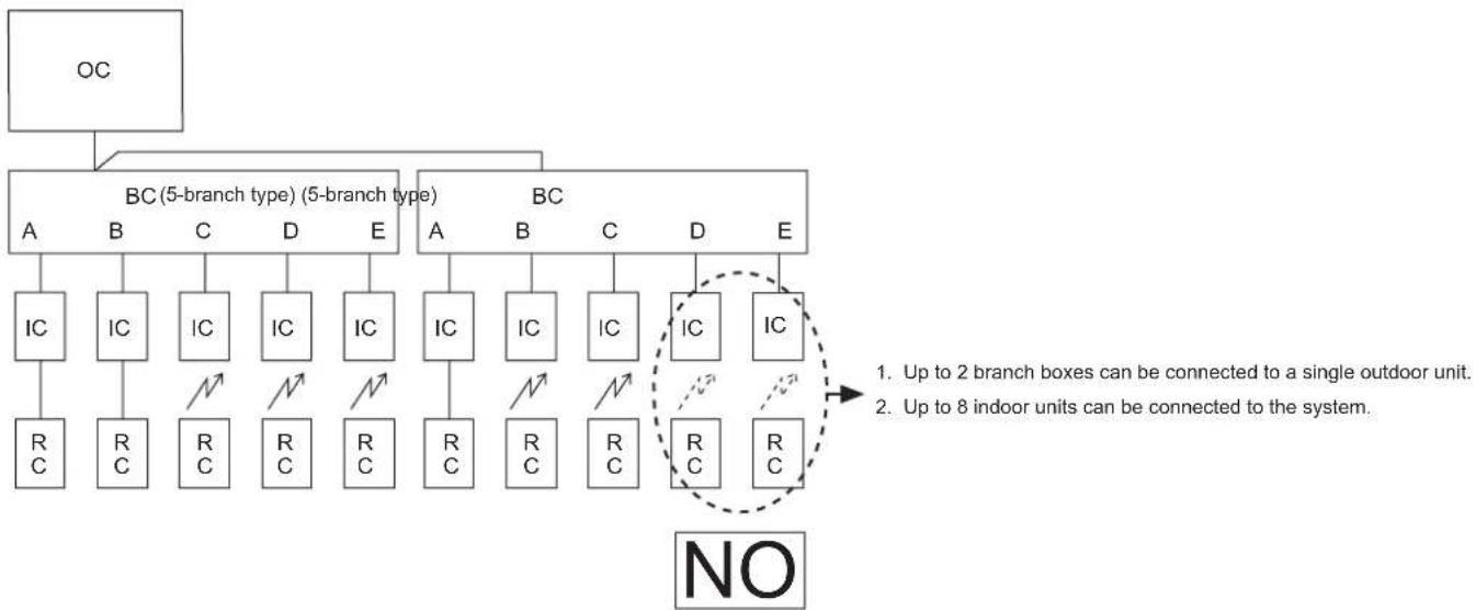
flowchart
graph TD
    A["OC"] --> B["BC (5-branch type) (5-branch type)"]
    B --> C1["IC"]
    B --> C2["IC"]
    B --> C3["IC"]
    B --> C4["IC"]
    B --> C5["IC"]
    B --> C6["IC"]
    B --> C7["IC"]
    B --> C8["IC"]
    B --> C9["IC"]
    B --> C10["IC"]
    B --> C11["IC"]
    B --> C12["IC"]
    B --> C13["IC"]
    B --> C14["IC"]
    B --> C15["IC"]
    B --> C16["IC"]
    B --> C17["IC"]
    B --> C18["IC"]
    B --> C19["IC"]
    B --> C20["IC"]
    B --> C21["IC"]
    B --> C22["IC"]
    B --> C23["IC"]
    B --> C24["IC"]
    B --> C25["IC"]
    B --> C26["IC"]
    B --> C27["IC"]
    B --> C28["IC"]
    B --> C29["IC"]
    B --> C30["IC"]
    B --> C31["IC"]
    B --> C32["IC"]
    B --> C33["IC"]
    B --> C34["IC"]
    B --> C35["IC"]
    B --> C36["IC"]
    B --> C37["IC"]
    B --> C38["IC"]
    B --> C39["IC"]
    B --> C40["IC"]
    B --> C41["IC"]
    B --> C42["IC"]
    B --> C43["IC"]
    B --> C44["IC"]
    B --> C45["IC"]
    B --> C46["IC"]
    B --> C47["IC"]
    B --> C48["IC"]
    B --> C49["IC"]
    B --> C50["IC"]
    B --> C51["IC"]
    B --> C52["IC"]
    B --> C53["IC"]
    B --> C54["IC"]
    B --> C55["IC"]
    B --> C56["IC"]
    B --> C57["IC"]
    B --> C58["IC"]
    B --> C59["IC"]
    B --> C60["IC"]
    B --> C61["IC"]
    B --> C62["IC"]
    B --> C63["IC"]
    B --> C64["IC"]
    B --> C65["IC"]
    B --> C66["IC"]
    B --> C67["IC"]
    B --> C68["IC"]
    B --> C69["IC"]
    B --> C70["IC"]
    B --> C71["IC"]
    B --> C72["IC"]
    B --> C73["IC"]
    B --> C74["IC"]
    B --> C75["IC"]
    B --> C76["IC"]
    B --> C77["IC"]
    B --> C78["IC"]
    B --> C79["IC"]
    B --> C80["IC"]
    B --> C81["IC"]
    B --> C82["IC"]
    B --> C83["IC"]
    B --> C84["IC"]
    B --> C85["IC"]
    B --> C86["IC"]
    B --> C87["IC"]
    B --> C88["IC"]
    B --> C89["IC"]
    B --> C90["IC"]
    B --> C91["IC"]
    B --> C92["IC"]
    B --> C93["IC"]
    B --> C94["IC"]
    B --> C95["IC"]
    B --> C96["IC"]
    B --> C97["IC"]
    B --> C98["IC"]
    B --> C99["IC"]
[3] Incorrect systems
3-1. Group operation by single remote controller
3-2. Group operation between different refrigerant systems
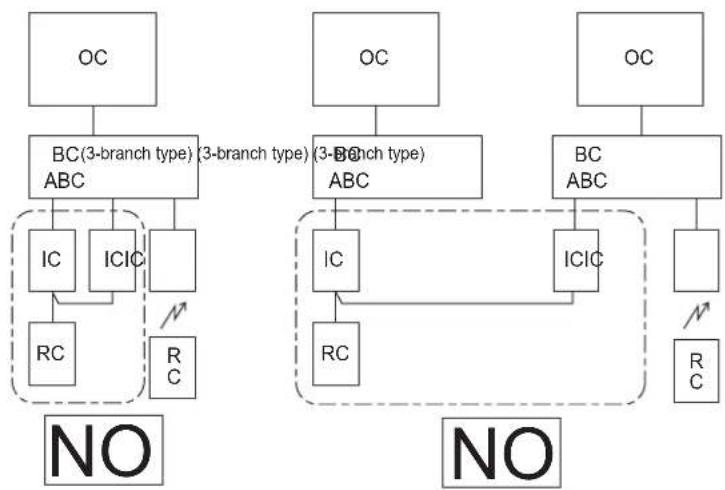
flowchart
graph TD
    subgraph NO
        A["OC"] --> B["BC(3-branch type) ABC"]
        B --> C["IC"]
        B --> D["ICIC"]
        C --> E["RC"]
        D --> F["R C"]
    end
    subgraph NO
        G["OC"] --> H["BC(3-branch type) ABC"]
        H --> I["IC"]
        H --> J["ICIC"]
        I --> K["RC"]
        J --> L["R C"]
    end
    style NO fill:#f9f,stroke:#333
    style NO fill:#ccf,stroke:#333
3-3. Connection of indoor units of CITY MULTI series.

flowchart
graph TD
    OC["OC"] --> BC["BC (5-branch type)"]
    BC --> A["A"]
    BC --> B["B"]
    BC --> C["C"]
    BC --> D["D"]
    BC --> E["E"]
    A --> IC1["IC"]
    B --> IC2["IC"]
    C --> IC3["IC"]
    D --> IC4["IC"]
    E --> IC5["IC"]
    A --> RC1["R_C"]
    B --> RC2["R_C"]
    C --> RC3["R_C"]
    D --> RC4["R_C"]
    E --> RC5["R_C"]
    IC1 --> NC1["NC"]
    IC2 --> NC2["NC"]
    IC3 --> NC3["NC"]
    IC4 --> NC4["NC"]
    IC5 --> NC5["NC"]
    IC6["IC * CITY MULTI"] --> NC6["NC"]
    NC6 --> RC6["R_C"]
    style NC6 stroke-dasharray: 5 5
3-4. Connection of M-NET Remote controller

flowchart
graph TD
    OC["OC"] --> BC["BC (5-branch type)"]
    BC --> A["A"]
    BC --> B["B"]
    BC --> C["C"]
    BC --> D["D"]
    BC --> E["E"]
    A --> IC1["IC"]
    B --> IC2["IC"]
    C --> IC3["IC"]
    D --> IC4["IC"]
    E --> IC5["IC"]
    IC1 --> RC1["R_C"]
    IC2 --> RC2["R_C"]
    IC3 --> RC3["R_C"]
    IC4 --> RC4["R_C"]
    IC5 --> RC5["R_C"]
    RC1 --> NC1["¬"]
    RC2 --> NC2["¬"]
    RC3 --> NC3["¬"]
    RC4 --> NC4["¬"]
    RC5 --> NC5["¬"]
    NC1 --> MNET["M-NET RC"]
    NC2 --> MNET
    NC3 --> MNET
    NC4 --> MNET
    NC5 --> MNET
    MNET -.-> NO["NO"]
3-1. Plural indoor units cannot be operated by a single remote controller.
3-2. Different refrigerant systems cannot be connected together.
3-3. Indoor units of CITY MULTI series cannot be connected to the branch boxes or outdoor unit.
3-4. If an MA remote controller is connected to this system, an M-NET remote controller cannot be connected.
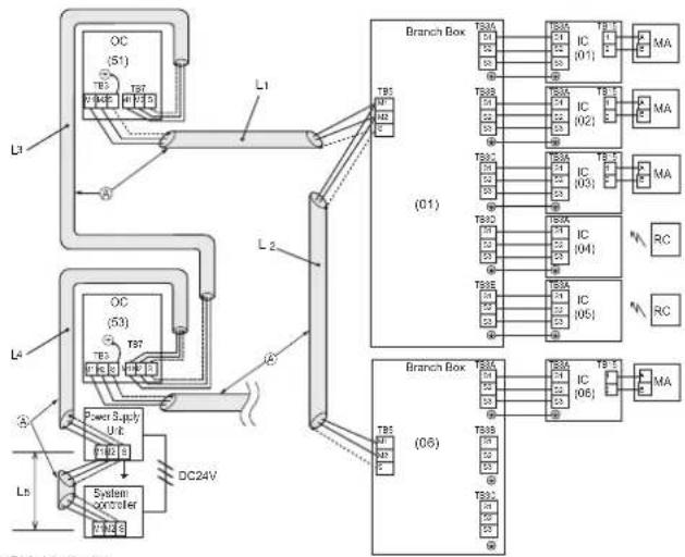
7.4. Branch box/outdoor wire connection and outdoor power supply cord connection (Fig. 7-2)
Warning:
- Be sure to attach the terminal block covers/panel of the outdoor unit securely. If it is not attached correctly, it could result in a fire or an electric shock due to dust, water, etc.
- Be sure to connect the power supply cords and the connecting wires for the indoor units, outdoor units, and branch boxes directly to the units (no intermediate connections).
Intermediate connections can lead to communication errors if water enters the cords or wires and causes insufficient insulation to ground or a poor electrical contact at the intermediate connection point.
(If an intermediate connection is necessary, be sure to take measures to prevent water from entering the cords and wires.)

Caution:
- Be careful not to make mis-wiring.
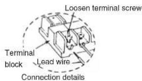
- Firmly tighten the terminal screws to prevent them from loosening.
• After tightening, pull the wires lightly to confirm that they not move. - If the connecting wire is incorrectly connected to the terminal block, the unit does not operate normally.
text_image
Loosen terminal screw. Terminal block Lead wire Connection details- Connect wire from the branch box correctly to the terminal block.
- For future servicing, give extra length to connecting wire.
flowchart
graph TD
    subgraph Power Supply Unit
        A["OC (51)"] --> B["T85"]
        C["OC (53)"] --> D["T97"]
        E["Power Supply Unit"] --> F["T81"]
        G["System controller"] --> H["DC24V"]
    end

    subgraph Branch Box
        I["T85"] --> J["IC (01)"]
        K["T86"] --> L["IC (02)"]
        M["T87"] --> N["IC (03)"]
        O["T88"] --> P["IC (04)"]
        Q["T89"] --> R["IC (05)"]
    end

    subgraph Branch Box
        S["T85"] --> T["IC (06)"]
        U["T86"] --> V["IC (07)"]
        W["T87"] --> X["IC (08)"]
        Y["T88"] --> Z["IC (09)"]
        AA["T89"] --> AB["IC (10)"]
    end

    L --> AC["MA"]
    N --> AD["MA"]
    P --> AE["RC"]
    Q --> AF["RC"]
    style Power Supply Unit fill:#f9f,stroke:#333
    style Branch Box fill:#ccf,stroke:#333
⑧: Shielded wire
( ) : Address example
Fig. 7-2
IMPORTANT
Make sure that the current leakage breaker is one compatible with higher harmonics.
Always use a current leakage breaker that is compatible with higher harmonics as this unit is equipped with an inverter.
The use of an inadequate breaker can cause the incorrect operation of inverter.
Longest length via outdoor units:
L_1 + L_2 + L_3 + L_4 + L_5 ≤ 500 m (1.25 mm^2 or more)
Longest transmission cable length
L_1 + L_2, L_3, L_3 + L_4, L_5 ≤ 200 m (1.25 mm ^2 or more)
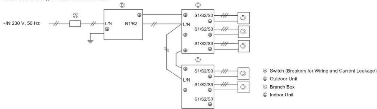
7.5. Wiring of main power supply and equipment capacity
Schematic Drawing of Wiring (Example) (Fig. 7-3)
flowchart
graph TD
    A["~N 230 V, 50 Hz"] --> B["L/N"]
    B --> C["B1/B2"]
    C --> D["S1/S2/S3"]
    C --> E["S1/S2/S3"]
    C --> F["S1/S2/S3"]
    D --> G["Outdoor Unit"]
    E --> H["Branch Box"]
    F --> I["Indoor Unit"]
    style A fill:#f9f,stroke:#333
    style B fill:#ccf,stroke:#333
    style C fill:#cfc,stroke:#333
    style D fill:#fcc,stroke:#333
    style E fill:#fcc,stroke:#333
    style F fill:#fcc,stroke:#333
    style G fill:#fff,stroke:#333
    style H fill:#fff,stroke:#333
    style I fill:#fff,stroke:#333
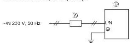
text_image
~N 230 V, 50 Hz A L/N ⊕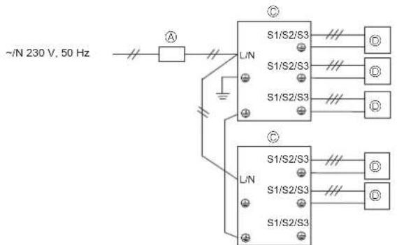
text_image
~N 230 V, 50 Hz S1/S2/S3 L/N S1/S2/S3 S1/S2/S3 S1/S2/S3 L/N S1/S2/S3 S1/S2/S3 S1/S2/S3Fig. 7-3
7. Electrical work
Thickness of Wire for Main Power Supply and On/Off Capacities
| Model | Power Supply | Minimum Wire Thickness (mm2) | Breaker for Wiring*1 | Breaker for Current Leakage | |||
| Main Cable Ground | |||||||
| Outdoor Unit ~/N 230 V, 50 Hz | Indoor Unit Power | When power is supplied separately | 5.5 (6) 5.5 (6) | 32 A 32 A 30 mA | 0.1 sec. or less | ||
| When power is supplied from the outdoor unit | 5.5 (6) 5.5 (6) | 40 A 40 A 30 mA | 0.1 sec. or less | ||||
| Indoor Unit | ~/N 230 V, 50 Hz | Refer to installation manual of indoor unit. | |||||
*1. A breaker with at least 3.0 mm contact separation in each poles shall be provided. Use non-fuse breaker (NF) or earth leakage breaker (NV).
| Total operating current of the indoor unit | Minimum wire thickness (mm2) Local switch (A) | Breaker for wiring (NFB) | Ground-fault interrupter *1 | ||||
| Main cable Branch Ground Capacity Fuse | |||||||
| F0 = 16 A or less *2 | 1.5 | 1.5 | 1.5 | 16 | 16 | 20 | 20 A current sensitivity *3 |
| F0 = 25 A or less *2 | 2.5 | 2.5 | 2.5 | 25 | 25 | 30 | 30 A current sensitivity *3 |
| F0 = 32 A or less *2 | 4.0 | 4.0 | 4.0 | 32 | 32 | 40 | 40 A current sensitivity *3 |
Apply to IEC61000-3-3 about max. permissive system impedance.
*1 The Ground-fault interrupter should support inverter circuit.
The Ground-fault interrupter should combine using of local switch or wiring breaker.
*2 Please take the larger of F1 or F2 as the value for F0.
F1 = Total operating maximum current of the indoor units × 1.2
F2 = (V1/C)
Connect to Branch box (PAC-MK·BC)
| Indoor unit | V1 | V2 | |
| Type 1 | SEZ-KD·VAQ(L), PCA-RP·KAQ, PLA-RP·BA | 19.8 | 2.4 |
| Type 2 | PEAD-RP·JAA | 26.9 | |
| Type 3 | SLZ-KA·VAQ(L) | 9.9 | |
| Type 4 | MSZ-FH·VE, MSZ-EF·VE, MSZ-GE·VAD | 6.8 | |
| Type 5 | MFZ-KJ·VE | 7.4 | |
| Type 6 | Branch box (PAC-MK·BC) | 5.1 | 3.0 |
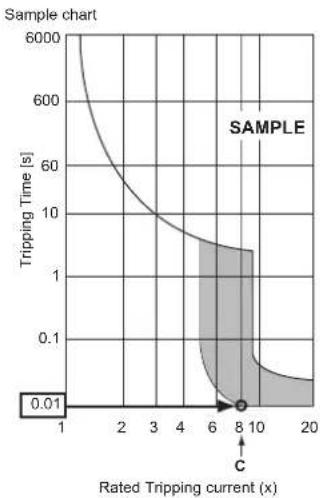
C : Multiple of tripping current at tripping time 0.01 s
Please pick up "C" from the tripping characteristic of the breaker.
*Condition: Branch Box + SEZ-KD-VA × 4 + SLZ-KA-VAQ(L), C=8 (refer to right sample chart)
F2 = 5.1 × 1/8 + 19.8 × 4/8 + 9.9 × 1/8
= 11.8
*3 Current sensitivity is calculated using the following formula.
G1 = V2 + V3 × (Wire length [km])
| G1 | Current sensitivity |
| 30 or less | 30 mA 0.1 sec or less |
| 100 or less | 100 mA 0.1 sec or less |
| Wire thickness (mm2) | V3 |
| 1.5 | 48 |
| 2.5 | 56 |
| 4.0 | 66 |
line
| Rated Tripping current (x) | Tripping Time [s] | | -------------------------- | ----------------- | | 1 | 6000 | | 2 | 4000 | | 3 | 2000 | | 4 | 1000 | | 6 | 500 | | 8 | 200 | | 10 | 100 | | 20 | 50 |Notes: 1. Wiring size must comply with the applicable local and national code.
- Power supply cords and indoor unit/branch box/outdoor unit connecting cords shall not be lighter than polychloroprene sheathed flexible cord. (Design 60245 IEC 57)
- Install an earth line longer than power cables.
- Do not bundle the M-NET cable with the connection cable and power supply cable.
It may cause erroneous operation.
Warning:
- If the power for the branch box is supplied from the terminal bed (TB1B) of the outdoor unit, please turn off the main power supply when servicing. And do not touch the B1, B2 terminals when the power is energized. If isolator should be used between outdoor unit and branch box/indoor unit and branch box, please use 3-pole type or 2-pole type. (Please refer to figure below.)
- Turn on the main power when the ambient temperature is -20^ or higher.
- Under conditions of -20^ , it needs at least 4hr stand by before the units operate in order to warm the electrical parts.
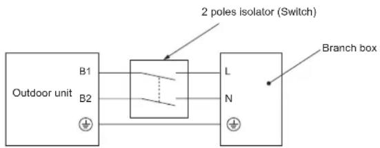
text_image
Outdoor unit B1 B2 2 poles isolator (Switch) L N Branch boxCaution:
After using the isolator, be sure to turn off and on the main power supply to reset the system. Otherwise, the outdoor unit may not be able to detect the branch box(es) or indoor units.
Be sure to connect the outdoor-branch box/indoor-branch box connecting cables directly to the units (no intermediate connections). Intermediate connections can lead to communication errors if water enters the cables and causes insufficient insulation to ground or a poor electrical contact at the intermediate connection point. (If an intermediate connection is necessary, be sure to take measures to prevent water from entering the cables.)
Never splice the power cable or the indoor-outdoor connection cable, otherwise it may result in a smoke, a fire or communication failure.
7.7. Address setting
Switch address setting
| UnitAddress | Outdoor | Branch Box | Indoor | |||||||||||||
| Address Connection Setting | ||||||||||||||||
| Switch |   tens onesdigit digitSWU2 SWU1 SW12 SW11 SW1 *SW1-6 not use tens onesdigit digitSWU2 SWU1 SW12 SW11 SW1 *SW1-6 not use |   tens onesdigit digit tens onesdigit digit | Port A B C D E -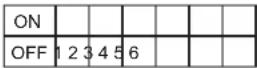 *ON: Indoor connectOFF: No connection *ON: Indoor connectOFF: No connection | None | ||||||||||||
| range 51 | -100 1 - 50 -- | |||||||||||||||
| setting | Branch address +50 | • According to the set address (for example, 01), the ad-dresses for the connected indoor units are set sequentially (for example, 02, 03, 04, and 05). | • Specify whether indoor units are connected to each port (A, B, C, D, and E). | There are no ad-dress settings for the indoor units. | ||||||||||||
| SW1 | 1 | 2 | 3 | 4 | 5 | SW1 | 1 | 2 | 3 | 4 | 5 | (6) | ||||
| ON | ON | ON | ON | ON | Port | A | B | C | D | E | (not use) | |||||
| Port | A | B | C | D | E | Indoor units are connected ONIndoor units are not connected OFF | ||||||||||
| Address | 01 | (SW11, 12) | ||||||||||||||
| 02 | 03 | 04 | 05 (sequential numbers) | |||||||||||||
Note: 1. Branch box address
When setting the address, use a number within the range 1–50.
Ex. The set address is (47) and there are 5 indoor units (A, B, C, D, and E).
If A: (47), B: (48), C: (49), D: (50), and E: (51), E is incorrect because it exceeds 50.
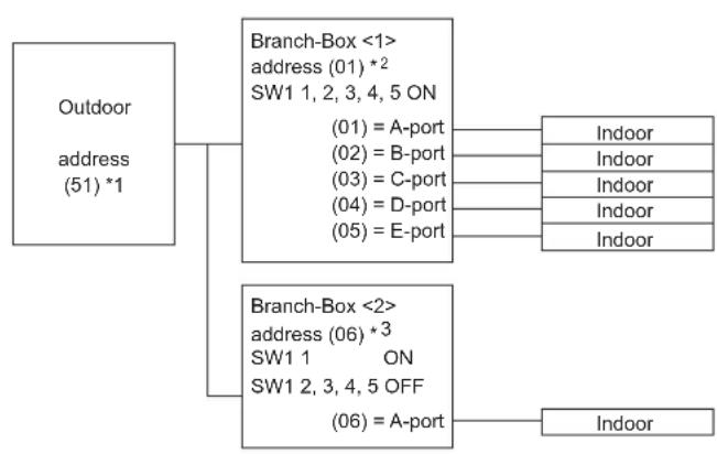
Ex1. Outdoor + Branch <1> (Indoor A, B, C, D, E) + Branch <2> (Indoor A)
flowchart
graph TD
    A["Outdoor address (51) *1"] --> B["Branch-Box <1> address (01) *2 SW1 1, 2, 3, 4, 5 ON"]
    A --> C["Branch-Box <2> address (06) *3 SW1 1 ON SW1 2, 3, 4, 5 OFF"]
    B --> D["Indoor"]
    B --> E["Indoor"]
    B --> F["Indoor"]
    B --> G["Indoor"]
    B --> H["Indoor"]
    C --> I["Indoor"]
    C --> J["Indoor"]
*1 Outdoor address
Branch Box <1> start address + 50 = 01 + 50 = 51
*2 Branch Box <1>
A-port address = Start address = 01
B-port address = Start address + 1 = 02
C-port address = Start address + 2 = 03
D-port address = Start address + 3 = 04
E-port address = Start address + 4 = 05
*3 Branch-Box <2>
Branch Box <2> start address
= Branch Box <1> oldest start address + 1
= 05 + 1 = 06
A-port address = Start address = 06
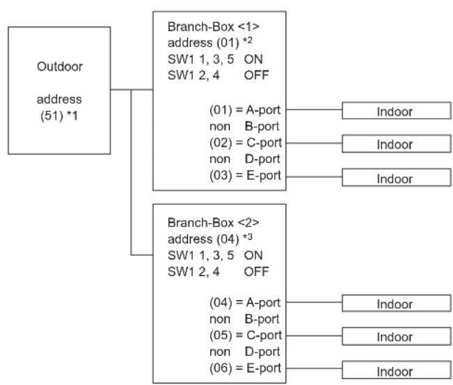
Ex2. Outdoor + Branch <1> (Indoor A, C, E) + Branch <2> (Indoor A, C, E)
flowchart
graph TD
    A["Outdoor address (51) *1"] --> B["Branch-Box <1> address (01) *2 SW1 1, 3, 5 ON SW1 2, 4 OFF"]
    B --> C["Indoor"]
    B --> D["Indoor"]
    B --> E["Indoor"]
    B --> F["(01) = A-port"]
    B --> G["non B-port"]
    B --> H["(02) = C-port"]
    B --> I["non D-port"]
    B --> J["(03) = E-port"]
    K["Branch-Box <2> address (04) *3 SW1 1, 3, 5 ON SW1 2, 4 OFF"]
    K --> L["Indoor"]
    K --> M["Indoor"]
    K --> N["(04) = A-port"]
    K --> O["non B-port"]
    K --> P["(05) = C-port"]
    K --> Q["non D-port"]
    K --> R["(06) = E-port"]
*1 Outdoor address
Branch Box <1> start address + 50 = 01 + 50 = 51
*2 Branch-Box <1>
A-port address = Start address = 01
B-port address no connection
C-port address = Start address + 1 = 02
D-port address no connection
E-port address = Start address + 2 = 03
*3 Branch-Box <2>
Branch Box <2> start address
= Branch Box <1> oldest start address + 1
= 03 + 1 = 04
A-port address = Start address = 04
B-port address no connection
C-port address = Start address + 1 = 05
D-port address no connection
E-port address = Start address + 2 = 06
8.1. Before test run
▶ After completing installation and the wiring and piping of the indoor and outdoor units, check for refrigerant leakage, looseness in the power supply or control wiring, wrong polarity, and no disconnection of one phase in the supply.
▶ Use a 500-volt M-ohm tester to check that the resistance between the power supply terminals and ground is at least 1 MΩ.
▶ Do not carry out this test on the control wiring (low voltage circuit) terminals.
Warning:
Do not use the air conditioner if the insulation resistance is less than 1 MΩ.
Insulation resistance
After installation or after the power source to the unit has been cut for an extended period, the insulation resistance will drop below 1 MΩ due to refrigerant accumulating in the compressor. This is not a malfunction. Perform the following procedures.
- Remove the wires from the compressor and measure the insulation resistance of the compressor.
- If the insulation resistance is below 1 MΩ, the compressor is faulty or the resistance dropped due the accumulation of refrigerant in the compressor.
-
After connecting the wires to the compressor, the compressor will start to warm up after power is supplied. After supplying power for the times indicated below, measure the insulation resistance again.
-
The insulation resistance drops due to accumulation of refrigerant in the compressor. The resistance will rise above 1M after the compressor is warmed up for 12 hours.
(The time necessary to warm up the compressor varies according to atmospheric conditions and refrigerant accumulation.) -
To operate the compressor with refrigerant accumulated in the compressor, the compressor must be warmed up at least 12 hours to prevent breakdown.
-
If the insulation resistance rises above 1 MΩ, the compressor is not faulty.

Caution:
- The compressor will not operate unless the power supply phase connection is correct.
- Turn on the power at least 12 hours before starting operation.
- Starting operation immediately after turning on the main power switch can result in severe damage to internal parts. Keep the power switch turned on during the operational season.
▶ The followings must be checked as well.
- The outdoor unit is not faulty. LED on the control board of the outdoor unit flash when the outdoor unit is faulty.
- Both the gas and liquid stop valves are completely open.
8.2. Test run
8.2.1. Using remote controller
Refer to the indoor unit installation manual.
- Be sure to perform the test run for each indoor unit. Make sure each indoor unit operates properly following the installation manual attached to the unit.
- If you perform the test run for all indoor units at once, you cannot detect any erroneous connection, if any, of the refrigerant pipes and the connecting wires.
* The compressor operation is not available for 3 minutes at least after the power is supplied. - The compressor can emit noise just after turn on the power supply or in case of low outside air temperature.
About the restart protective mechanism
Once the compressor stops, the restart preventive device operates so the compressor will not operate for 3 minutes to protect the air conditioner.
8.2.2. Using SW3 in outdoor unit
Note:
In case of the test run from outdoor unit, all indoor units operate. Therefore, you can not detect any erroneous connection of refrigerant pipes and the connecting wires. If it aims at detection of any erroneous connection, be sure to carry out the test run from remote controller with reference to "8.2.1 Using remote controller."
| SW3-1 ON | Cooling operation | |
| SW3-2 OFF | ||
| SW3-1 ON | Heating operation | |
| SW3-2 ON |
* After performing the test run, set SW3-1 to OFF.
- A few seconds after the compressor starts, a clanging noise may be heard from the inside of the outdoor unit. The noise is coming from the check valve due to the small difference in pressure in the pipes. The unit is not faulty.
The test run operation mode cannot be changed by DIP switch SW3-2 during the test run. (To change the test run operation mode during the test run, stop the test run by DIP switch SW3-1. After changing the test run operation mode, resume the test run by switch SW3-1.)
8.3. Refrigerant collecting (Pump down)
Perform the following procedures to collect the refrigerant when moving the indoor unit or the outdoor unit.
① Turn off the circuit breaker.
② Connect the low pressure side of the gauge manifold to the service port of the gas side stop valve.
③ Close the liquid stop value.
④ Supply power (circuit breaker).
* Start-up of the indoor-outdoor communication takes about 3 minutes after the power (circuit breaker) is turned on. Start the pump-down operation 3 to 4 minutes after the power (circuit breaker) is turned ON.
⑤ Confirm that SW3-2 is set to OFF, and then set SW3-1 to ON to perform the test run for cooling operation. The compressor (outdoor unit) and ventilators (indoor and outdoor units) start operating and test run for cooling operation begins. Immediately after performing the test run for cooling operation, set the outdoor service switch SW2-4 (pump down switch) from OFF to ON.
* Do not continue to operate for a long time with the switch SW2-4 set to ON. Make sure to switch it to OFF after pump down is completed.
⑥ Fully close the gas stop valve when the pressure reading on the gauge drops 0.05 - 0.00 MPa (approximately 0.5 - 0.0 kgf/cm²)
⑦ Set SW3-1 to OFF to stop the air conditioner operation. (Set the outdoor service switch SW2-4 from ON to OFF.)
⑧ Turn off the power supply (circuit breaker).
* If too much refrigerant has been added to the air conditioner system, the pressure may not drop to 0.05 MPa (0.5 kgf/cm ^2 ). If this occurs, use a refrigerant collecting device to collect all of the refrigerant in the system, and then recharge the system with the correct amount of refrigerant after the indoor and outdoor units have been relocated.
Warning:
When pumping down the refrigerant, stop the compressor before disconnecting the refrigerant pipes. The compressor may burst and cause injury if any foreign substance, such as air, enters the system.
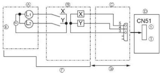
9.1. OUTDOOR UNIT INPUT/OUTPUT CONNECTOR
• State (CN51)
flowchart
graph TD
    A["Component A"] --> L1["L1"]
    A --> L2["L2"]
    L1 --> X["X"]
    L2 --> X
    X --> Y["Y"]
    Y --> X
    X --> Y
    Y --> X
    X --> Y
    Y --> X
    X --> 5["5"]
    5 --> 4["4"]
    4 --> 3["3"]
    3 --> 0["0"]
    0 --> ①[①]
    ②[②] --> ③[③]
    ③ --> ④[④]
    ④ --> ⑤[⑤]
    ⑤ --> ⑥[⑥]
    ⑥ --> ⑦[⑦]
    ⑦ --> ⑧[⑧]
    ⑧ --> ⑨[⑨]
    style A fill:#f9f,stroke:#333
    style B fill:#ccf,stroke:#333
    style C fill:#cfc,stroke:#333
    style D fill:#fcc,stroke:#333
    style E fill:#ffc,stroke:#333
    style F fill:#fcc,stroke:#333
    style G fill:#fcc,stroke:#333
    style H fill:#fcc,stroke:#333
    style I fill:#fcc,stroke:#333
    style J fill:#fcc,stroke:#333
    style K fill:#fcc,stroke:#333
    style L fill:#cff,stroke:#333
    style M fill:#cff,stroke:#333
    style N fill:#cff,stroke:#333
    style O fill:#cff,stroke:#333
    style P fill:#cff,stroke:#333
    style Q fill:#cff,stroke:#333
    style R fill:#cff,stroke:#333
    style S fill:#cff,stroke:#333
Ⓐ Distant control board
® Relay circuit
© External output adapter (PAC-SA88HA-E)
© Outdoor unit control board
© Lamp power supply
⑤ Procure locally
© Max. 10 m
L1: Error display lamp
L2: Compressor operation lamp
X, Y: Relay (Coil standard of 0.9W or less for DC 12V)
X, Y: Relay (DC1mA)
• Auto change over (CN3N)
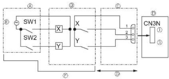
flowchart
graph TD
    A["Switch SW1"] --> B["X"]
    C["Switch SW2"] --> D["Y"]
    B --> E["X"]
    D --> F["Y"]
    E --> G["CN3N"]
    F --> G
    G --> H["Output ①"]
    style A fill:#f9f,stroke:#333
    style C fill:#f9f,stroke:#333
    style B fill:#ccf,stroke:#333
    style E fill:#ccf,stroke:#333
    style F fill:#ccf,stroke:#333
    style G fill:#cfc,stroke:#333
    style H fill:#fcc,stroke:#333
Ⓐ Remote control panel
⑧ Relay circuit
© External input adapter (PAC-SC36NA-E)
Outdoor unit control board
© Relay power supply
⑤ Procure locally
© Max. 10 m
| ON | OFF | |
| SW1 | Heating | Cooling |
| SW2 | Validity of SW1 | Invalidity of SW1 |
- Demand Response Mode (CN3S, CN3D)
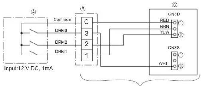
text_image
Input:12 V DC, 1mA Common DRM3 DRM2 DRM1 C 3 2 1 CN3D RED ① BRN ② YLW ③ CN3S WHT ① ② ③Ⓐ DRED (Demand controller)
® Terminal bed
© Outdoor unit control board
The wiring between Ⓑ and Ⓞ is completed before shipping from the factory.
This product is capable of all three Demand Response Mode (DRM1, 2, 3). (DRED compliant to AS/NZS 4755.3.1:2012)
| Demand Response Mode | Description |
| DRM1 | Compressor Off. |
| DRM2 | Total electrical energy consumption of the system is not more than 50%. |
| DRM3 | Total electrical energy consumption of the system is not more than 75%. |
- Silent Mode / Demand Control (CN3D)
To use this function, DIP switch SW5-1 must be set to OFF and the existing CN3S and CN3D lead wires must be removed. In addition, this function cannot be used at the same time as the Demand Response Modes above.
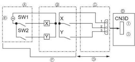
flowchart
graph TD
    A["SW1"] --> B["X"]
    C["SW2"] --> D["Y"]
    B --> E["X"]
    D --> F["Y"]
    E --> G["CN3D"]
    F --> G
    G --> H["①"]
    G --> I["③"]
    style A fill:#f9f,stroke:#333
    style C fill:#f9f,stroke:#333
    style B fill:#ccf,stroke:#333
    style E fill:#ccf,stroke:#333
    style F fill:#ccf,stroke:#333
    style G fill:#cfc,stroke:#333
    style H fill:#fcc,stroke:#333
    style I fill:#fcc,stroke:#333
Ⓐ Remote control panel
⑧ Relay circuit
© External input adapter (PAC-SC36NA-E)
Outdoor unit control board
© Relay power supply
⑤ Procure locally
© Max. 10 m
The silent mode and the demand control are selected by switching the DIP switch 9-2 on outdoor controller board. It is possible to set it to the following power consumption (compared with ratings) by setting SW1, 2.
| Outdoor controller board DIP SW9-2 $W1 SW2 Function | ||||
| Silent mode OFF ON – Silent mode operation | ||||
| Demand control ON OFF OFF 100 % (Normal) | ON OFF 75%ON ON 50%OFF ON 0 % (Stop) | |||
This product is designed and intended for use in the residential, commercial and light-industrial environment.
Please be sure to put the contact address/telephone number on this manual before handing it to the customer.