CA1155E - Car alarm AUDIOVOX - Free user manual and instructions
Find the device manual for free CA1155E AUDIOVOX in PDF.


| Product Type | Car Alarm System |
| Brand | Audiovox |
| Model | CA1155E |
| Control Module Dimensions | Approx. 4.0 x 3.0 x 1.2 inches |
| Control Module Weight | Approx. 0.5 lb |
| Power Supply | 12V DC Vehicle Battery |
| Remote Key Fob Battery | CR2032 or similar (typical) |
| Operating Frequency | 315 MHz (typical) |
| Control Range | Up to 500 feet (line of sight) |
| Main Functions | Remote arming/disarming, shock sensor, siren, LED indicator, panic alarm, door lock/unlock outputs, trunk release (optional) |
| Security Features | Starter interrupt, false alarm prevention, valet mode, auto re-arm, silent mode |
| Inputs/Outputs | 6 programmable trigger inputs, 2 auxiliary outputs, negative trigger door lock interface |
| Siren Output | 6-tone siren, adjustable duration |
| Reset/Clear | Valet switch or remote button combination |
| Installation Type | Professional installation recommended |
| Maintenance | Check backup battery (if present), clean contacts, ensure proper grounding |
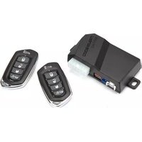
| Included Components | Control module, remote key fobs (2), siren, shock sensor, LED, wiring harness, installation manual |
| Optional Accessories | Glass break sensor, tilt sensor, additional remote |
| Warranty | Limited lifetime (Audiovox typical) |
Frequently Asked Questions - CA1155E AUDIOVOX
User questions about CA1155E AUDIOVOX
0 question about this device. Answer the ones you know or ask your own.
Ask a new question about this device
Download the instructions for your Car alarm in PDF format for free! Find your manual CA1155E - AUDIOVOX and take your electronic device back in hand. On this page are published all the documents necessary for the use of your device. CA1155E by AUDIOVOX.
USER MANUAL CA1155E AUDIOVOX
Vehicle Security and
Keyless Entry System
IMPORTANT NOTE: The operation of the Security and Convenience System as described in this manual is applicable to most vehicles. However, due to the configuration of some vehicles, some functions AND/OR SAFETY PRECAUTIONS may not apply. Please see your installing dealer for more information.
Using Your Remote Control....3
Arming the Security System....3
Bypassing the Shock Sensor .... 3
Disarming the Security System 3
Two Stage Door Unlock (optional)....3
Activating Trunk Release (optional)....3
Activating AUX 1 (optional)....4
Using the Progressive Car Finder Feature....4
Using the Personal Protection Alarm....4
Valet Mode 4
User Selectable Notification Chirps....4
User Selectable LED 5
Manually Overriding the Security System 5
Carjack Mode 5
Status LED, Light Flashes and Siren/Horn Indications .... 6
Remote Control Buttons & Functions....7
Replacing Remote Control Batteries....7
Warranty Information 8
Using Your Remote Control
Arming the Security System
To arm the system, exit the vehicle, close all doors, then press the 📋 button. The parking lights will flash 2 times, indicating the system is armed, has locked the doors (if equipped and connected) and activated the starter disable feature. The LED status indicator will blink steadily, once per second.
NOTE: The system is equipped with a feature called Silent Choice. If enabled, the system requires a second press of the button to activate an audible arming response from the vehicle.
Bypassing The Shock Sensor
To arm the system and ignore the shock sensor press ⏻ button, then within 5 seconds press ⏻+, the system will respond with 1 long chirp.
NOTE: The system will only change the shock sensor setting for one arm cycle and will be defaulted back to normal operation the next time the system is armed.
Disarming the Security System
To disarm the system press the ⚡ button. The parking lights will flash 1 time, indicating the system is disarmed and has unlocked the doors (if equipped and connected).
NOTE: The system is equipped with a feature called Silent Choice. If enabled, the system requires a second press of the button to activate an audible disarming response from the vehicle. If your system is set up for 2 step unlock, a third press of unlock will activate the audible response.
Two Stage Door Unlock (Optional)
If this feature is enabled on your system, pressing the button one time will unlock only the driver's door. Press again within three seconds to unlock the remaining doors.
Activating the Trunk Release Feature (Optional)
If this feature is enabled on your system, pressing and holding the 📋 button for 3 seconds will open the vehicle's trunk or hatch.
Activating the AUX 1 Output (Optional)
If this feature is enabled on your system, pressing the ⏻ and ⏱ buttons simultaneously will activate an optional feature. This feature can be programmed for a wide range of functions like power window or sunroof automation, please consult your installing dealer to determine the functionality of your system.
Using the Progressive Car Finder Feature
Press the button to locate your vehicle. The system will flash the parking lights and sound 5 times at low volume, increasing in volume each time the button is pressed.
Using the Personal Protection Alarm (Panic)
Press and hold the button for 3 seconds to activate the personal protection alarm. During panic mode, the normal function of the transmitter buttons will be suspended. The transmitter's and buttons can be used to lock and unlock the door (if the option is installed). To stop the alarm, press and hold the button on the transmitter again for 3 seconds. The system will automatically stop after 30 seconds.
Valet Mode
When valet mode is activated the status LED will light solid, and all security functions will be disabled. To enter or exit valet mode simply follow the steps outlined below:
- Turn the vehicle's ignition ON.
- Push and hold the programming/valet button.
- The LED will turn on solid when valet mode is active
- Release the programming/valet button.
User Selectable Notification Chirps
System ARM / DISARM chirps can be toggled ON or OFF without entering the programming feature banks.
- Turn the ignition ON then OFF.
- Press and release the valet/programming button 3 times. The system will respond with 1 chirp for ON or 2 chirps for OFF.
User Selectable LED
This feature will control whether the LED is ON or OFF when the system is Armed/Locked and can be toggled ON or OFF without entering the programming feature banks.
- Turn the ignition ON, OFF, ON, OFF.
- Press and release the valet/programming button 3 times. The system will respond with 1 chirp for ON or 2 chirps for OFF.
Manually Overriding the Security System
Your system can be disarmed without the use of the transmitter. This is necessary, since you will need the ability to operate your vehicle if the transmitter is lost or its battery fails. To by-pass the alarm system;
- Open the vehicle door. The alarm will sound.
- Turn the ignition key to the ON position.
- Within 10 seconds, press and release the valet push button switch.
The alarm system will stop sounding and enter the (by-passed) mode. You can now start and operate the vehicle normally.
Carjack Mode (Anti-Hijack Mode)
This feature must be turned on in system programming, please consult your installing dealer.
Triggering Carjack mode: While the ignition is ON and press and hold + for 2 seconds, the parking lights will flash 1 time and the system will act as follows;
- 50 seconds after being triggered the siren will chirp for 15 seconds, during this 15 seconds you will be alerted to push the valet button to turn off Carjack mode. If Carjack mode is not turned off at this time it will advance to the next step.
- Following the 15 second chirps (total time now 65 seconds) the siren will go into full sound and the parking lights will start flashing.
- 90 seconds after trigger in, addition to the siren and parking lights, the system will activate the starter kill. THE SYSTEM WILL REMAIN IN THIS STATE UNTIL THE BATTERY IS DEPLETED.
OVERRIDE THE SYSTEM TO TURN OFF CARJACK MODE: Turn the ignition OFF then On and press the valet button within 10 seconds.
Status LED, Light Flashes, and Siren/Horn Indications
Status LED Flash Indications
LED Flashes Function
OFF Disarmed
Slow Flash Armed
Fast Flash Passive Arming Countdown
ON (Solid) Valet Mode
2 Flashes Zone 2 Trigger, Hood / Trunk
3 Flashes Zone 3 Trigger, Door
4 Flashes Zone 4 Trigger, Shock Sensor
5 Flashes Zone 5 Trigger, Ignition
6 Flashes Zone 6 Trigger, Tilt Sensor
Siren/Horn Chirp Indications
Chirps Function
1 Disarm
| 2 | Arm |
| 3 | Door Ajar Upon Arming |
| 4 | Disarm / Triggered |
| 5 | Car Find |
Parking Light Flash Indications
Flashes Function
| 1 | Disarm | |
| 2 | Arm | |
| 3 | Disarm / Triggered | |
| 5 | Car Find |
Remote Control Buttons & Functions
| 4-Button Transmitter | Lock | Unlock | Trunk | Car Find / Panic | Operation Method |
| Lock X | Press and Release | ||||
| Unlock X | Press and Release | ||||
| Trunk X | Push and Hold (3 Sec) | ||||
| Car Finder | X | Press and Release | |||
| Panic | X | Push and Hold (3 Sec) | |||
| AUX 1 X | X | Push and Hold (3 Sec) | |||
| Shock Bypass | X | X | Press and Release Lock then Press Lock + Car Find (within 5 Sec) |
Replacing Remote Control Batteries
4 Button Remote Control - Model CAT4ME
The batteries inside each remote control should last approximately 1 year under normal use. When the batteries become weak you will notice the remote control range (the distance from the vehicle the remote control will work) deteriorate and the small LED on the remote control will dim. To replace the remote control batteries:
- Remove 1 screw then disassemble the halves of the remote control by unsnapping the back of the case.
- Remove the old battery, observing the +/- symbols on the batteries and replace with a new battery.
- Reassemble the halves of the remote control and reinstall 1 screw.
- Test operation of the remote control.
CODE ALARM
LIMITED LIFETIME WARRANTY
Applies to Code Alarm Series Control Modules, Sirens, Sensors, and Relays.
Voxx Electronics Corporation (the Company) warrants to the original purchaser of this product that should this product or any part thereof, (other than transmitters) under normal use and conditions, be proven defective in material or workmanship during the lifetime of the vehicle, in which it was originally installed from the date of original purchase such defect(s) will be repaired or replaced with new or reconditioned product, (at the Company's option) without charge for parts or repair labor. A transmitter is warranted for 12 months from the date of original purchase.
To obtain repair or replacement within the terms of this Warranty, the product is to be delivered with proof of warranty coverage (e.g. dated bill of sale), specification of defect(s), transportation prepaid, to an approved warranty station. This Warranty is not transferable.
This Warranty does not cover damage to the vehicle's electrical system or costs incurred for removal or reinstallation of the product. This Warranty does not cover batteries, broken LCD or OLED display screens, nor apply to any product or part thereof which, in the opinion of the Company, has suffered or been damaged through alteration, improper installation, mishandling, misuse, abuse, neglect, accident, or by removal or defacement of the factory serial number/bar code label(s).
This Warranty is in lieu of all other express warranties or liabilities. ANY IMPLIED WARRANTIES, INCLUDING ANY IMPLIED WARRANTY OF MERCHANTABILITY, SHALL BE LIMITED TO THE DURATION OF THIS WRITTEN WARRANTY. IN NO CASE SHALL THE COMPANY BE LIABLE FOR ANY CONSEQUENTIAL OR INCIDENTAL DAMAGES FOR BREACH OF THIS OR ANY OTHER WARRANTY. No person or representative is authorized to assume for the Company any liability other than expressed herein in connection with the sale of this product.
The company does not warrant that this product cannot be compromised or circumvented. THE EXTENT OF THE COMPANY'S LIABILITY UNDER THIS WARRANTY IS LIMITED TO THE REPAIR OR REPLACEMENT PROVIDED ABOVE AND, IN NO EVENT, SHALL THE COMPANY'S LIABILITY EXCEED THE PURCHASE PRICE PAID BY PURCHASER FOR THE PRODUCT WITHOUT COST OF INSTALLATION.
Some states do not allow limitations on how long an implied warranty lasts or the exclusion or limitation of incidental or consequential damage so the above limitations or exclusions may not apply to you. This Warranty gives you specific legal rights and you may also have other rights which vary from state to state.
Voxx Electronics Corporation, 180 Marcus Blvd., Hauppauge, New York 11788 / 1-800-645-4994
Voxx Electronics Corporation. Customer Service 1-800-421-3209 WWW.CODE-ALARM.COM
FCC COMPLIANCE
This device complies with Part 15 of the FCC rules and with RSS-210 of
Industry Canada. Operation is subject to the following two conditions:
- This device may not cause harmful interference, and
- This device must accept any interference received, including any interference that may cause undesired operation.
Warning!
Changes or modifications not expressly approved by the party responsible for compliance could void the user's authority to operate the equipment.
PATENTED: www.voxxintl.com/company/patents
CODE ALARM
ELITE SERIES
Installation and Reference Guide
ca1155E
Security and Keyless Entry
Table of Contents
Before You Begin....3
Wire Connection Guide....4
12 Pin Main Harness....6
10 Pin Input / Output Harness....9
Door Locks 12
Additional Ports....13
LED Port....13
Programming Port 13
DBI Port....13
Digital Tilt / Shock Sensor 14
Set Up & Programming 15
Transmitter Programming....15
Manual Feature Programming....15
Shock Sensor Programming, Adjustment and Testing 16
Programming Feature Banks 17
PC Based Feature Programming / Firmware Updates - (Optional)......19
Dome Light Delay / Theater Dimming 20
Chirp Delete - User Accessible....20
User Selectable LED 20
Feature Descriptions....21
Transmitter Button Functions 27
Security Trigger Zones......27
System Layout....28
Thank you for trusting Code Alarm products! If you are a consumer, please note: Professional installation is strongly recommended.
This manual assumes the installer has adequate knowledge of the following expertise, and as such, it does not cover these topics in detail:
12-volt electronics
Testing and verifying circuits
Making safe and lasting wiring connections
Factory ignition, power, lighting, data bus and sensing systems
Factory systems and components to avoid
Safe wire routing, circuit protection and product placement
Access to vehicle-specific technical information
In addition, this manual assumes the installer has the proper tools, skill and facilities to perform a professional installation.
Performing an improper installation could void your vehicle warranty and/or result in damage to the vehicle or its components, improper system function, unsafe vehicle operation or physical injury.
If you are an authorized Code Alarm installation technician, please use this manual as a more detailed addendum to the Installation Quick Reference Guide that accompanies the Code Alarm system. You can download a printable PDF of the quick reference guide at voxxuniversity.com.

Technical Support (800) 421-3209
or go to
www.voxxuniversity.com
System Layout
This diagram shows the available harnesses and connection. Note that you may not use all connections and modules in your installation.
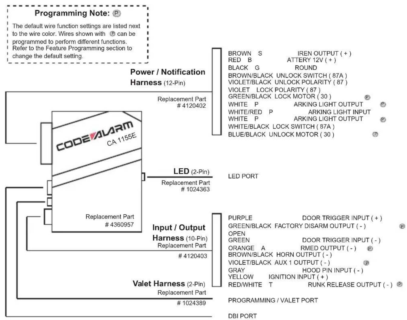
flowchart
graph TD
    A["Power / Notification Harness (12-Pin)"] --> B["Replacement Part # 4120402"]
    A --> C["LED (2-Pin)"]
    A --> D["Input / Output Harness (10-Pin)"]
    A --> E["Valet Harness (2-Pin)"]
    B --> F["BROWN S IREN OUTPUT (+) RRED B ATTERY 12V (+) BLACK G ROUND BROWN/BLACK UNLOCK SWITCH (87A) VIOLET/BLACK UNLOCK POLARITY (87) VIOLET LOCK POLARITY (87) GREEN/BLACK LOCK MOTOR (30) P WHITE P ARKING LIGHT OUTPUT P WHITE/RED P ARKING LIGHT INPUT WHITE P ARKING LIGHT OUTPUT P WHITE/BLACK LOCK SWITCH (87A) BLUE/BLACK UNLOCK MOTOR (30) P"]
    C --> G["LED PORT"]
    D --> H["PURPLE DOOR TRIGGER INPUT (+) GREEN/BLACK FACTORY DISARM OUTPUT (-) OPEN GREEN DOOR TRIGGER INPUT (-) ORANGE A RMED OUTPUT (-) BROWN/BLACK HORN OUTPUT (-) VIOLET/BLACK AUX 1 OUTPUT (-) GRAY HOOD PIN INPUT (-) YELLOW IGNITION INPUT (+) RED/WHITE T RUNK RELEASE OUTPUT (-) P PROGRAMMING / VALET PORT DBI PORT"]
    E --> I["# 1024389"]
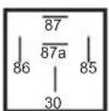
STARTER INTERRUPT RELAY & HARNESS
Replacement Part #1024405
ORANGE
RED
BLACK
WHITE / BLACK
OPEN
86 - ARMED OUTPUT (-)
85 - IGNITION (+)
87A - STARTER OUTPUT - MOTOR SIDE
30 - STARTER INPUT - KEY SIDE
87 - OPEN
Installation Note:
The module should be securely attached to a stable surface using zip ties in order for the on-board shock and tilt sensor to function properly.
12 Pin Main Harness
| 12 PIN MAIN - POWER / LOCKS | 1 | BROWN | SIREN OUTPUT (+) |
| 2 | RED | BATTERY 12V (+) | |
| 3 | BLACK | G ROUND | |
| 4 | BROWN/BLACK | UNLOCK SWITCH (87A) | |
| 5 | VIOLET/BLACK | UNLOCK POLARITY (87) | |
| 6 | WHITE/BLACK | LOCK SWITCH (87A) | |
| 7 | GREEN/BLACK | LOCK MOTOR (30) | |
| 8 | WHITE | PARKING LIGHT OUTPUT | |
| 9 | WHITE/RED | PARKING LIGHT INPUT | |
| 10 | WHITE | PARKING LIGHT OUTPUT | |
| 11 | VIOLET | LOCK POLARITY (87) | |
| 12 | BLUE/BLACK | UNLOCK MOTOR (30) |
10 Pin Input / Output Harness
| 10 PIN INPUT / OUTPUT | 1 | PURPLE | DOOR TRIGGER INPUT ( + ) |
| 2 | GREEN/BLACK | FACTORY DISARM OUTPUT (-) | |
| 3 | OPEN | ||
| 4 | GREEN | DOOR TRIGGER INPUT (-) | |
| 5 | ORANGE | GROUND WHEN ARMED OUTPUT (-) | |
| 6 | BROWN/BLACK | HORN OUTPUT (-) | |
| 7 | VIOLET/BLACK | AUX 1 (-) | |
| 8 | GRAY | HOOD PIN INPUT (-) | |
| 9 | YELLOW | IGNITION INPUT (+) | |
| 10 | RED/WHITE | TRUNK RELEASE OUTPUT (-) |
Locate a suitable mounting location in the engine compartment for the siren, away from moving parts.
With the bell of the siren aiming downwards, secure the siren in place using self tapping screws, being careful not do drill into any hoses, wiring or components.
Connect the BLACK siren wire to a chassis ground using a ring terminal and self tapping screw (not supplied).
Route the BROWN siren output wire from the control module through the firewall and connect to the RED wire on the siren.
NOTE: Be sure to loom the siren wires, and seal the grommet.
2 RED BATTERY 12V (+)
Locate 1 of the vehicle's constant 12 Volt battery wires at the ignition switch.
Verification: This wire will register (+) voltage in all positions of the ignition switch.
Connect the RED wire to the constant 12 Volt battery wire.
NOTE: Remove all fuses until all connections are made.
3
BLACK
GROUND
Connect the BLACK wire to a solid chassis ground point using a ring terminal and self tapping screw (not supplied). Scrape away paint from the grounding point to ensure a good connection. The recommended grounding point is a metal surface in the driver's side kick panel area.
NOTE: Do not ground the BLACK wire with any other vehicle components.
4 BROWN/BLACK UNLOCK SWITCH (87A)
Refer to the Door Lock Section on page 11 of this guide.
5 VIOLET/BLACK UNLOCK POLARITY (87)
Refer to the Door Lock Section on page 11 of this guide.
6 WHITE/BLACK LOCK SWITCH (87A)
Refer to the Door Lock Section on page 11 of this guide.
7 GREEN/BLACK LOCK MOTOR (30)
Refer to the Door Lock Section on page 11 of this guide.
8 WHITE PARKING LIGHT OUTPUT
9 WHITE/RED PARKING LIGHT INPUT
10 WHITE PARKING LIGHT OUTPUT
Locate the parking light output wire at the vehicle's light switch.
Verification: This wire registers positive voltage when the parking lights are turned on.
Positive switching Parking Lights:
Connect the WHITE/RED wire to a 15 Amp max fused battery source.
Connect the WHITE wire to the parking light output wire.
Negative switching Parking Lights:
Connect the WHITE/RED wire to a good chassis ground.
Connect the WHITE wire to the parking light output wire.
11 VIOLET LOCK POLARITY (87)
Refer to the Door Lock Section on page 11 of this guide.
12 BLUE/BLACK UNLOCK MOTOR (30)
Refer to the Door Lock Section on page 11 of this guide.
1 PURPLE DOOR TRIGGER INPUT (+)
Locate the vehicle's dome light or door pin switch wire.
Verification: This wire will register positive voltage (POS) when the door is opened and the interior light is on. This wire will register ground or "0" Volts when the door is closed and the interior light is off.
Connect the PURPLE wire to the vehicle's positive door input wire(s).
NOTE: Certain vehicles may require multiple connections. Refer to vehicle application guide
2 GREEN/BLACK FACTORY DISARM (-)
This wire will supply a (-) 300mA pulse both upon disarming the system and when the trunk release feature is activated. Locate the factory perimeter alarm disarm wire from the key cylinder inside the drivers door.
Verification: This wire registers ground if the key is turned to the unlock position in the driver's door cylinder.
Connect the GREEN/BLACK wire to the factory alarm disarm wire.
3 OPEN
4 GREEN DOOR TRIGGER INPUT (-)
Locate the vehicle's dome light or door pin switch wire.
Verification: This wire will register ground (NEG) when the door is opened and the interior light is on. This wire will register positive voltage when the door is closed and the interior light is off.
Connect the GREEN wire to the vehicle's negative door input wire(s).
NOTE: Certain vehicles may require multiple connections. Refer to vehicle application guide
5 ORANGE GROUND WHEN ARMED OUTPUT (-)
This wire will have a continuous (-) 300mA output when the system is Armed. This wire is typically used for controlling window modules or additional sensors.
6 BROWN/BLACK HORN OUTPUT (-)
Locate the vehicle's horn wire.
Verification: This wire will register at positive voltage and register ground when the horn switch is pressed.
Connect the BROWN/BLACK wire to the vehicle's horn wire. This is a low current output, 300mA.
7 VIOLET/BLACK AUX 1 OUTPUT (-)
This wire provides a ( - ) 300mA output capable of driving relays. For Control of optional accessories (i.e. Power Window/Sunroof, etc.).
To activate refer to the transmitter button configuration chart. Please refer to the selectable options for timing.
8 GRAY HOOD PIN INPUT (-)
Install a Hood Pin Switch and connect to the GRAY wire.
Verification: This wire when connected will register ground when the vehicle's hood is opened.
Connect the GRAY wire to the hood pin.
NOTE: Be sure to loom the wire, and seal the grommet.
9 YELLOW IGNITION INPUT (+)
Locate the vehicle's ignition wire at the ignition switch.
Verification: This wire registers voltage when the key is turned to the ON (or RUN) position. The voltage does not drop out when the key is turned to the START (or CRANK) position.
Connect the YELLOW wire to the vehicle's Ignition wire.
10 RED/WHITE TRUNK RELEASE OUTPUT (-)
Locate the vehicle's trunk release wire at the trunk release switch.
Verification: This wire will register either positive voltage or ground when the trunk release is activated.
This is a low current output, 300mA.
Door Locks
1 BROWN/BLACK UNLOCK SWITCH (87A)
2 BLUE/BLACK UNLOCK MOTOR (30)
3 VIOLET/BLACK UNLOCK POLARITY (87)
4 WHITE/BLACK LOCK SWITCH (87A)
5 GREEN/BLACK LOCK MOTOR (30)
6 VIOLET LOCK POLARITY (87)
The door lock / unlock outputs are designed to control several different types of systems which may require additional parts.
3 Wire Ground Switched Door Locks:
Connect the GREEN/BLACK wire to the wire that provides a ground signal from the factory door lock switch to the factory door lock control relay.
Connect the BLUE/BLACK wire to the wire that provides a ground signal from the factory door unlock switch to the factory door lock control relay.
Connect the VIOLET and the VIOLET/BLACK wires to a solid chassis ground point. The WHITE/BLACK and BROWN/BLACK wires are not required for this type of door lock/unlock system.
3 Wire Positive Switched Door Locks:
Connect the GREEN/BLACK wire to the wire that provides a +12 volt signal from the factory door lock switch to the factory door lock control relay.
Connect the BLUE/BLACK wire to the wire that provides a +12 volt signal from the factory door unlock switch to the factory door lock control relay.
Connect the VIOLET and the VIOLET/BLACK wires to a +12 volt battery source. The WHITE/BLACK and BROWN/BLACK wires are not required for this type of door lock/unlock system.
LED Port
The LED included in the kit will serve as a visual indicator of the alarm's status. It should be installed in the dash, located where it can be easily seen from outside the vehicle, yet not be distracting to the driver. Once a location has been selected, check behind the panel for wire routing access, and to confirm the drill will not damage any existing components as it passes through the panel. Drill a 1/4" hole, and pass the red and blue wires from the LED through the hole, from the front of the panel. Firmly press the body of LED into the hole until fully seated.
Programming / Valet Button Port
Select a mounting location that is within reach of the ignition switch, as this switch in combination with the ignition switch, will be used to program the certain features of the system. It is suggested that the switch be mounted to the lower dash panel in the driver's area within reach of the driver.
DBI Port - 4 Pin Data Bus Interface
The DBI port is used for external Flashlogic data immobilizer & door lock Interface modules to communicate with the vehicle's databus. When using the DBI port to control Flashlogic modules please refer to the D2D (Data to Data) function list available per vehicle firmware on the tech service web site.
Digital Tilt / Shock Sensor
The systems digital tilt and shock sensor is onboard and part of the main module. Mount the module to a firm wire harness, or other stable location, that will allow the sensor to pick up vibrations due to impact to the vehicle or if the vehicle is lifted / tilted.
When the security system is armed a light impact to the vehicle will trigger the system's warn-away feature chirping the horn/siren several short times, a harder impact will trigger the system's full-trigger mode.
To adjust the shock sensor, refer to Shock SensorProgramming, Adjustment and Testing.
To adjust the tilt sensor, refer to Digital Tilt Setting in option programming.
NOTE: During remote start, the system will ignore the sensor upon ignition until after remote start shutdown.
Transmitter Programming - Feature Bank 1
- Turn the ignition ON.
- Press and hold the valet/override button.
- Within 10 seconds the system will chirp (3) three times.
- Press 1 button of each transmitter you wish to program.
- The system will respond with 1 chirp for each accepted transmitter.
- Pressing the override button at anytime during programming will advance to the next bank.
NOTE: The system will exit transmitter programming after 15 seconds of inactivity.
NOTE: This system has 1 button programming which programs all channels of the system.
NOTE: The system will hold up to 4 transmitters in memory, programming a 5th transmitter will erase the oldest transmitter in memory.
Manual Feature Programming - Feature Bank 2 & 3
- Turn the ignition ON.
- Press and hold the valet/override button.
- Within 10 seconds the system will chirp (3) three times.
- Use the valet/override button to advance through each option bank. For feature programming advance to Feature Bank 2 or 3, which is (4) four or (5) five chirps.
- Use the transmitter button to scroll through the selections in each feature bank, the system will chirp to match the feature number.
- Press the transmitter button to change the desired feature. The LED will flash indicating the changed feature.
Defaulting All Features: Pressing the button anytime while in any of the feature banks will default all features and return you to feature bank 2 - 4 chirps.
NOTE: The system will remain in feature programming mode as long as the ignition is on, there is no time limit. To exit programming turn the IGNITION OFF.
Manual Feature Programming - Feature Bank 4 & 5 - N/A
Reserved for future expansion
Shock Sensor Programming, Adjustment and Testing - Feature Bank 6
- Turn the ignition ON.
- Press and hold the valet/override button.
- Within 10 seconds the system will chirp (3) three times.
- Use the valet/override button to advance through each option bank. For Shock Sensor Adjustment advance to Feature Bank 6, which is (8) eight chirps.
- Turn the ignition OFF, exit the vehicle and close all doors.
- Select Auto-Learning or Manual Adjustment:
Option (a) Auto-Learning
a1. Press and hold the transmitter button until the system emits 2 long chirps to enter Shock Sensor Auto-Learning Mode.
a2. Strike the vehicle to set the level intended for the system to trigger.
a3. The system will store the setting, chirp 1 time and automatically advance to step 7, Manual Adjustment and Testing.
Option (b) Manual Adjustment
b1. Press and hold the transmitter button until the system emits 1 long chirp to advance to step 7, Manual Adjustment and Testing.
- Manual Adjustment and Testing. Adjustment and testing can be performed at any time during this step. During testing 3 short chirps indicates warn-away, 1 long chirp indicates full trigger. Allow 3 sec. between each adjustment / test.
a. Full trigger – Press the transmitter button to increase sensitivity. Press the button to decrease sensitivity.
b. Warn-Away – Press the 📋 button to increase sensitivity. Press the 🔊 button to decrease sensitivity.
- Programming will exit by turning the ignition ON or if there is no activity for 60 seconds. The system will flash the parking lights 3 times to confirm exit.
Note: Sensitivity ranges from 0 (OFF) – 27 (most sensitive), the default setting is 4. The system will chirp when sensitivity is raised or lowered with 2 chirps indicating the highest or lowest setting.
Defaulting the Shock Sensor: Enter Feature Bank 6, step 6 and press and hold the UNLOCK button for 3 seconds, the system will emit 1 long chirp to confirm reset and will return to step 6. Continue with step 6 or exit programming.
Refer to transmitter programming.
| Feature Bank 2 - 4 Chirps Security Control | 1 LED Flash | 2 LED Flash | 3 LED Flash | 4 LED Flash | 5 LED Flash | 6 LED Flash | |
| 1 | Silent Choice | ON | OFF | ||||
| 2 | Door Locks | Active | Passive | ||||
| 3 | System Arming | Active | Passive | ||||
| 4 | System Notifications | Siren & Horn | Siren Only | Horn Only | |||
| 5 | Alarm Duration | 30 Seconds | 60 Seconds | ||||
| 6 | Security | ON | OFF | ON w/ OEM Remote Start | |||
| 7 | Anti-Hijack Mode | OFF | ON | ||||
| 8 | Ground While Armed Orange (-) Output | Ground While Armed | Ground While Disarmed | ||||
| 9 | DBI Port Protocol | DBI | ADS | ||||
| 10 | Arm / Disarm Chirps | Standard: 2 - Arm 1 - Disarm | Inverted: 1 - Arm 2 - Disarm | ||||
| 11 | LED Indicator | ON | OFF | ||||
| 12 | Auto Re-lock | OFF | Lock Only | Arm & Lock | |||
| 13 | Extended Parking Lights | OFF | After Unlock | After Lock | After Lock & Unlock | ||
| 14 | Parking Light Relay / Trunk (-) Output | Standard | Inverted | ||||
| 15 | Digital Tilt Sensor | 3 Degrees of Tilt | 1 Degree of Tilt | OFF | |||
| Feature Bank 3 - 5 Chirps Output Control | 1 LED Flash | 2 LED Flash | 3 LED Flash | 4 LED Flash | 5 LED Flash | 6 LED Flash | |
| 1 | Lock / Unlock Timing | 1 Sec. | 3.5 Sec. | 1 Sec. Lock, 2x Unlock | 30 Sec. Lock, 2x Unlock | 2x Lock, 1 Sec. Unlock | 0.5 Sec. |
| 2 | Factory Disarm Lt Green / Black | Factory Disarm | 2nd Unlock | Factory Disarm 2x 500mS | Factory Disarm 350mS | Factory Disarm 5 00mS | Factory Disarm w/ Unlock Timing |
| 3 | Ignition Locks | OFF | Lock / Unlock | Lock Only | Unlock Only | ||
| 4 | Trunk Output Timing | 1 Sec. | 10 Sec. | 20 Sec. | Latched until IGN ON | Latched ON until Button Press | |
| 5 | Horn Output Timing | 16mS | 10mS | 30mS | 40mS | 50mS | |
| 6 | Real Panic | ON | OFF | ||||
| 7 | AUX 1 Violet / Black Output | Push and Hold | Latched | Latched until IGN ON | Dome Light Output |
| Feature Bank 4 - 6 ChirpsN/A |
| Feature Bank 5 - 7 ChirpsN/A |
| Feature Bank 6 - 8 ChirpsShock Sensor Adjustment | |
| Refer to section - Shock Sensor Adjustment |
Code Alarm Utility App
Feature Programming / Firmware Updates (optional)
The new Code Alarm Utility App is able to set feature options, save frequently used feature configurations as well as update module firmware.
PC System Requirements:
Windows XP SP3 or above
Min 1GB RAM
Net Framework 4.0 or above
Screen Resolution - Suggested 1280x1024 or above
Required Accessory & PC Software:
VEPROG Programmer Accessory
CA Utility App
VEPROG drivers
Download and Install the Required Drivers:
- To download the Code Alarm Utility App visit the Voxx University website at voxxuniversity.com (registration/login required).
- Select VOXXTECH and locate the utility app under the heading Software Downloads.
- The Code Alarm Utility App download includes both the CA Utility app and necessary VEPROG drivers.
- Install both items before attempting to update modules.
Use a PC and VEPROG tool for Feature Programming or Firmware Updates:
- Launch the Code Alarm Utility App.
- Connect the VEPROG to your PC via the USB port.
- Connect the VEPROG to the Code Alarm Module.
- Select the features you wish to change or update firmware if needed.
Dome Light Delay / Theater Dimming
The system can be programmed to delay arming after the lock button is pressed (60 second max) for vehicles with a dome light delay or theater dimming feature. Once programmed the system will ‘learn’ the timing of the dome light delay and add 2 seconds before arming.
- Close all doors with ignition off.
- Using the transmitter press LOCK, UNLOCK, LOCK, UNLOCK, LOCK, UNLOCK, LOCK. The LED will light solid to indicate the system has entered DOME DELAY LEARN MODE.
- Immediately OPEN then CLOSE the door WITHOUT disarming the system. The system will then monitor the door trigger wire. Once the dome light turns off, the system will then add 2 seconds and then exit the learning mode.
- The LED will begin to flash indicating the system has exited the learning mode and is now armed.
Defaulting the Dome Light Delay: Turn the ignition ON then OFF 3 times then press and hold the valet button for 5 seconds, the system will chirp 1 time indicating the learned delay time has been cleared.
Chirp Delete - User Accessible
System ARM/DISARM chirps can be toggled ON or OFF without entering the programming feature banks.
- Turn the ignition ON then OFF.
- Press and release the valet/programming button 3 times. The system will respond with 1 chirp for ON or 2 chirps for OFF.
User Selectable LED
This feature will control whether the LED is ON or OFF when the system is Armed/Locked. This will be selectable in feature programming OR on-the-fly without entering the programming feature banks.
- Turn the ignition ON, OFF, ON, OFF.
- Press and release the valet/programming button 3 times. The system will respond with 1 chirp for ON or 2 chirps for OFF.
Feature Bank 2 - Security
1 - Silent Choice: Controls the normal arm/disarm chirps of the security system.
ON - Silent arming/disarming upon first press of lock/unlock, pressing lock/unlock a second time will activate the arm/disarm chirps respectively. The system will only sound the arm/disarm chirps upon a second press of the lock/unlock buttons.
OFF - normal arm/disarm chirps upon the first press of lock/unlock.
2 - Door Locks: Determines manual or automatic locking of the vehicle's doors.
Active - Requires use of the transmitter to lock the vehicle's doors.
Passive - Automatically locks the vehicle's doors 1 minute after the last door is closed.
Note: For Passive Locks, feature #3, System Arming, must also be set to passive.
3 - System Arming: Determines manual or automatic locking of the vehicle's doors.
Active - Requires use of the transmitter to arm the security system.
Passive - Automatically arms the security system 1 minute after the last door is closed
4 - System Notifications: This feature selects which output(s) will sound the system's arm/disarm chirps. This feature does not effect the triggered state of the security system and during a triggered cycle, both the siren and horn outputs will activate respectively.
Siren & Horn – Siren and horn both sound when arming/disarming the system.
Siren Only – Only the siren will sound when arming/disarming the system.
Horn Only - Only the horn will sound when arming/disarming the system.
5 - Alarm Duration: Determines the length of time the system will sound the siren/horn during a full trigger event.
30 Seconds – When triggered, the system will sound the siren/horn for 30 seconds then stop. The unit will remain armed and may be triggered again.
60 Seconds – When triggered, the system will sound the siren/horn for 60 seconds then stop. The unit will remain armed and may be triggered again.
6 - Security: Controls security functionality - ON / OFF.
ON - Full security functionality.
OFF - The security system does not trigger. Panic and all other convenience features operate as normal.
ON w/OEM Remote Start Compatibility - This will prevent a vehicle's factory remote start from triggering the security system when activated. The system will use the ignition input to shunt shock and door inputs until 5 seconds after they clear. If the alarm is triggered prior to ignition on, then ignition will not shunt/cancel the alarm's triggered state. Also, note that the ignition input will no longer serve as a trigger if this option is selected on.
7 - Anti-Hijack Mode: Controls Car Jack mode - ON / OFF.
OFF - Standard security system operation.
ON - Enables Car Jack mode functionality as described in the owners manual
8 - Ground While Armed / Orange Output: Controls the output of the orange wire.
This wire will either supply a ( - ) output when armed OR disarmed.
9 - DBI Port Protocol: Determines the protocol type in which the DBI port uses to
interface with external modules.
DBI Protocol
ADS Protocol
10 - Arm/Disarm Chirps: Determines the number of chirps and parking light flashes when the system is armed/disarmed.
Standard - 2 chirps/light flashes with arm, 1 chirp/light flash with disarm.
Inverted - 1 chirp/light flash with arm, 2 chirps/light flashes with disarm.
11 - LED Indicator: Control of the LED when the system is armed / locked.
ON - LED will flash when system is armed / locked
OFF – LED will not flash when system is armed / locked. Only applies to normal operation (armed/locked) and does not affect programming, valet mode, diagnostics, passive lock countdown or PTN
12 - Auto Re-Lock: When Auto Re-lock is selected, the system will re-lock the vehicle after 3 minutes if the system was disarmed and a door was NOT opened within that set amount of time. A door opening within this time cancels Auto Re-Lock.
Note: This feature is separate from Passive/Active Arming
OFF – Standard operation.
Lock Only – The unit will re-lock the vehicle after 3 minutes if the system was disarmed and a door was NOT opened within that time.
Arm & Lock (security units only) - The system will arm and also re-lock the vehicle after 3 minutes if the system was disarmed and a door was NOT opened within that time.
13 - Extended Parking Lights: When selected, this feature will keep the parking lights on for an additional 30 seconds after the standard flashes when pressing lock or unlock.
OFF – Normal parking light function.
After Unlock – Parking lights will stay on for 30 seconds after normal unlock flashes.
After Lock - Parking lights will stay on for 30 seconds after normal lock flashes.
After Lock & Unlock - Parking lights will stay on for 30 seconds after normal lock and unlock flashes.
14 - Parking Light Relay / Trunk ( - ) Output: This feature gives the installer the ability to swap the functions of the Parking Light Relay & Trunk Output.
Standard – No change to outputs.
Inverted - When inverted, the Trunk Red / White (-) Output will function as the Parking Light Output and the Parking Light White & White/ Red will function as the Trunk Output.
15 - Parking Light Relay / Trunk ( - ) Output: Controls the angle of tilt needed to trigger the alarm. Note that the zero point for the tilt sensor is calibrated each time the system arms. The sensor will also reset the zero point after the alarm cycle when triggered by tilt.
3 Degrees of Tilt – The alarm will trigger when the vehicle is tilted 3 degrees.
1 Degree of Tilt – The alarm will trigger when the vehicle is tilted 1 degree.
OFF – The tilt sensor is inactive and will not trigger the system.
Feature Bank 3 - Output Control
1 - Lock / Unlock Timing: Controls the timing of the BLUE and GREEN lock output wires.
1 Sec. - Single 1 second lock pulse, single 1 second unlock pulse.
3.5 Sec. - Single 3.5 second lock pulse, single 3.5 second unlock pulse.
1 Sec. Lock, 2x Unlock - Single 1 second lock pulse, double 1 second unlock pulse.
30 Sec. Lock, 2x Unlock - Single 30 second lock pulse, double 1 second unlock pulse.
2x Lock, 1 Sec. Unlock - Double 1 second lock pulse, single 1 second unlock pulse.
0.5 Sec. Pulse - Single 0.5 second lock pulse, single 0.5 second unlock pulse.
2 - Factory Disarm, Lt Green/Black Output: Controls the timing of the LT. GREEN/BLACK factory disarm output.
Factory Disarm - Single 1 second pulse with unlock and remote start activation.
2nd Unlock - Same output timing as unlock with 2nd press of unlock only.
Factory Disarm 2x 500mS - Double 500mS second pulse with unlock and remote start activation.
Factory Disarm 350mS - Single 350mS second pulse with unlock and remote start activation.
Factory Disarm 500mS - Single 500mS second pulse with unlock and remote start activation.
Factory Disarm w/ Unlock Timing – Uses the timing option set for Unlock in Bank 3, Feature 1.
3 - Ignition Locks: Control of door locks when the ignition is cycled ON or OFF.
OFF - Door locks not activated by ignition.
Lock / Unlock - Doors lock when ignition is turned on and unlock when ignition is turned off.
Lock Only - Doors lock when ignition is turned on.
Unlock Only - Doors unlock when ignition is turned off.
4 - Trunk Output Timing: Control of the RED/WHITE trunk release output wire when trunk release is activated from the transmitter.
1 Sec. - 1 second pulse output.
10 Sec. - Continuous output for 10 seconds.
20 Sec. - Continuous output for 20 seconds.
Latched until IGN ON - Continuous output until the vehicle's ignition is turned ON.
Latched ON until Button Press - Continuous output until the activation button is pressed again.
5 - Horn Output Timing: Control the minimum horn pulse time in milliseconds, some vehicle will require a longer pulse to activate the factory horn.
16mS
10mS
30mS
40mS
50mS
6 - Real Panic: Controls the panic out when triggered from the transmitter.
ON - Randomized horn honks when panic is triggered.
OFF - Standard pattern horn honks when panic is triggered.
7 - AUX 1 - Violet/Black Output: Controls the VIOLET/BLACK AUX 1 output activation type and timing.
Push and Hold - Output is continuously active until transmitter button is released.
Latched - Output stays active until button is pressed again.
Latched until IGN ON - Output stays active until the ignition is turned on.
Dome Light Output - Output is used for illuminated entry and is not controlled by the AUX 1 function of the transmitter.
Feature Bank 4 & 5 - N/A
Reserved for future expansion
Feature Bank 6 -
Shock Sensor Programming, Adjustment and Testing
- Turn the ignition ON.
- Press and hold the valet/override button.
- Within 10 seconds the system will chirp (3) three times.
- Use the valet/override button to advance through each option bank. For Shock Sensor Adjustment advance to Feature Bank 6, which is (8) eight chirps.
- Turn the ignition OFF, exit the vehicle and close all doors.
- Select Auto-Learning or Manual Adjustment:
Option (a) Auto-Learning
a1. Press and hold the transmitter button until the system emits 2 long chirps to enter Shock Sensor Auto-Learning Mode.
a2. Strike the vehicle to set the level intended for the system to trigger.
a3. The system will store the setting, chirp 1 time and automatically advance to step 7, Manual Adjustment and Testing.
Option (b) Manual Adjustment
b1. Press and hold the transmitter button until the system emits 1 long chirp to advance to step 7, Manual Adjustment and Testing.
- Manual Adjustment and Testing. Adjustment and testing can be performed at any time during this step. During testing 3 short chirps indicates warn-away, 1 long chirp indicates full trigger. Allow 3 sec. between each adjustment / test.
a. Full trigger – Press the transmitter button to increase sensitivity. Press the button to decrease sensitivity.
b. Warn-Away – Press the 📄 button to increase sensitivity. Press the 🔊 button to decrease sensitivity.
- Programming will exit by turning the ignition ON or if there is no activity for 60 seconds. The system will flash the parking lights 3 times to confirm exit.
Note: Sensitivity ranges from 0 (OFF) – 27 (most sensitive), the default setting is 4. The system will chirp when sensitivity is raised or lowered with 2 chirps indicating the highest or lowest setting.
Defaulting the Shock Sensor: Enter Feature Bank 6, step 6 and press and hold the UNLOCK button for 3 seconds, the system will emit 1 long chirp to confirm reset and will return to step 6. Continue with step 6 or exit programming.
Transmitter Button Functions
| 4-Button Transmitter | Lock | Unlock | Trunk | Car Find / Panic | Operation Method |
| Lock X | Press and Release | ||||
| Unlock X | Press and Release | ||||
| Trunk X | Push and Hold (3 Sec) | ||||
| Car Finde r | X | Press and Release | |||
| Panic | X | Push and Hold (3 Sec) | |||
| AUX 1 X | X | Push and Hold (3 Sec) | |||
| Shock Bypass | X | X | Press and Release Lock then Press Lock + Car Find (within 5 Sec) |
Security Trigger Zones
If the security system has been triggered the LED will ash one of the patterns below indicating the zone.
LED FLASHES TRIGGER ZONE
2 Flashes Hood / Trunk Input
3 Flashes Door Input
4 Flashes Shock Sensor
5 Flashes Ignition Input
6 Flashes Tilt Sensor
Programming Note:

The default wire function settings are listed next to the wire color. Wires shown with Ⓟ can be programmed to perform different functions.
Refer to the Feature Programming section to change the default setting.

flowchart
graph TD
    A["Power / Notification Harness (12-Pin)"] --> B["Replacement Part # 4120402"]
    A --> C["LED (2-Pin)"]
    A --> D["Input / Output Harness (10-Pin)"]
    A --> E["Valet Harness (2-Pin)"]
    B --> F["CA 1155E"]
    C --> G["Replacement Part # 1024363"]
    D --> H["Replacement Part # 4360957"]
    E --> I["Replacement Part # 1024389"]
BROWN S IREN OUTPUT (+)
RED B ATTERY 12V (+)
BLACK G ROUND
BROWN/BLACK UNLOCK SWITCH (87A)
VIOLET/BLACK UNLOCK POLARITY (87)
VIOLET LOCK POLARITY (87)
GREEN/BLACK LOCK MOTOR (30)
WHITE P ARKING LIGHT OUTPUT
WHITE/RED P ARKING LIGHT INPUT
WHITE P ARKING LIGHT OUTPUT
WHITE/BLACK LOCK SWITCH (87A)
BLUE/BLACK UNLOCK MOTOR (30)
LED PORT
PURPLE DOOR TRIGGER INPUT (+)
GREEN/BLACK FACTORY DISARM OUTPUT (-)
OPEN
GREEN DOOR TRIGGER INPUT (-)
ORANGE A RMED OUTPUT (-)
BROWN/BLACK HORN OUTPUT (-)
VIOLET/BLACK AUX 1 OUTPUT (-)
GRAY HOOD PIN INPUT (-)
YELLOW IGNITION INPUT (+)
RED/WHITE T RUNK RELEASE OUTPUT (-)
PROGRAMMING / VALET PORT
DBI PORT
STARTER INTERRUPT RELAY & HARNESS
Replacement Part #1024405

ORANGE
RED
BLACK
WHITE / BLACK
OPEN
86 - ARMED OUTPUT (-)
85 - IGNITION (+)
87A - STARTER OUTPUT - MOTOR SIDE
30 - STARTER INPUT - KEY SIDE
87 - OPEN
Installation Note:
The module should be securely attached to a
stable surface using zip ties in order for the
on-board shock and tilt sensor to function properly.
VOXX Electronics Corporation. Customer Service 1-800-421-3209 WWW.CODE-ALARM.COM
FCC COMPLIANCE
This device complies with Part 15 of the FCC rules and with RSS-210 of Industry Canada. Operation is subject to the following two conditions:
- This device may not cause harmful interference, and
- This device must accept any interference received, including any interference that may cause undesired operation.
Warning!
Changes or modifications not expressly approved by the party responsible for compliance could void the user's authority to operate the equipment.
CODE ALARM
PROFESSIONAL SERIES
Security and Keyless Entry Installation Quick Reference Guide for model:
ca1155E
Complete guides also available at www.voxxuniversity.com
2019 Voxx Electronics Corporation. All rights reserved.
4280988
Dome Light Delay / Theater Dimming
The system can be programmed to delay arming after the lock button is pressed (60 second max) for vehicles with a dome light delay or theater dimming feature. Once programmed the system will 'learn' the timing of the dome light delay and add 2 seconds before arming.
- Close all doors with ignition off.
- Using the transmitter press LOCK, UNLOCK, LOCK, UNLOCK, LOCK, UNLOCK, LOCK. The LED will light solid to indicate the system has entered DOME DELAY LEARN MODE.
- Immediately OPEN then CLOSE the door WITHOUT disarming the system. The system will then monitor the door trigger wire. Once the dome light turns off, the system will then add 2 seconds and then exit the learning mode.
- The LED will begin to flash indicating the system has exited the learning mode and is now armed.
Defaulting the Dome Light Delay: Turn the ignition ON then OFF 3 times then press and hold the valet button for 5 seconds, the system will chirp 1 time indicating the learned delay time has been cleared.
Security Trigger Zones
If the security system has been triggered the LED will flash one of the patterns below indicating the zone.
| LED FLASHES | TRIGGER ZONE |
| 2 Flashes | Hood / Trunk Input |
| 3 Flashes | Door Input |
| 4 Flashes | Shock Sensor |
| 5 Flashes | Ignition Input |
| 6 Flashes | Tilt Sensor |
Programming Note: Ⓟ
The default wire function settings are listed next to the wire color. Wires shown with Ⓗ can be programmed to perform different functions. Refer to the Feature Programming section to change the default setting.
Power / Notification Harness (12-Pin)
Replacement Part
4120402

| BROWN | SIREN OUTPUT (+) |
| RED | BATTERY 12V (+) |
| BLACK | GROUND |
| BROWN/BLACK | UNLOCK SWITCH (87A) |
| VIOLET/BLACK | UNLOCK POLARITY (87) |
| VIOLET | LOCK POLARITY (87) |
| GREEN/BLACK | LOCK MOTOR (30) P |
| WHITE | PARKING LIGHT OUTPUT P |
| WHITE/RED | PARKING LIGHT INPUT |
| WHITE | PARKING LIGHT OUTPUT P |
| WHITE/BLACK | LOCK SWITCH (87A) |
| BLUE/BLACK | UNLOCK MOTOR (30) P |
SHOCK SENSOR PORT
LED PORT
| PURPLE | DOOR TRIGGER INPUT (+) |
| GREEN/BLACK | FACTORY DISARM OUTPUT (-) ☑ |
| OPEN | |
| GREEN | DOOR TRIGGER INPUT (-) |
| ORANGE | ARMED OUTPUT (-) ☑ |
| BROWN/BLACK | HORN OUTPUT (-) |
| VIOLET/BLACK | AUX 1 OUTPUT (-) ☑ |
| GRAY | HOOD PIN INPUT (-) |
| YELLOW | IGNITION INPUT (+) |
| RED/WHITE | TRUNK RELEASE OUTPUT (-) ☑ |
PROGRAMMING / VALET PORT
DBI PORT
STARTER INTERRUPT RELAY & HARNESS
Replacement Part #1024405

ORANGE
RED
BLACK
WHITE / BLACK
OPEN
86 - ARMED OUTPUT (-)
85 - IGNITION (+)
87A - STARTER OUTPUT - MOTOR SIDE
30 - STARTER INPUT - KEY SIDE
87 - OPEN
Installation Note:
The module should be securely attached to a stable surface using zip ties in order for the on-board shock and tilt sensor to function properly.
Feature Bank 1 - 3 Chirps Transmitter Programming
Refer to transmitter programming.
| Feature Bank 2 - 4 Chirps Security Control | 1 LED Flash | 2 LED Flash | 3 LED Flash | 4 LED Flash | 5 LED Flash | 6 LED Flash | |
| 1 | Silent Choice | ON | OFF | ||||
| 2 | Door Locks | Active | Passive | ||||
| 3 | System Arming | Active | Passive | ||||
| 4 | System Notifications | Siren & Horn | Siren Only | Hom Only | |||
| 5 | Alarm Duration | 30 Seconds | 60 Seconds | ||||
| 6 | Security | ON | OFF | ON w/ OEM Remote Start | |||
| 7 | Anti-Hijack Mode | OFF | ON | ||||
| 8 | Ground While Armed Orange (-) Output | Ground While Armed | Ground While Disarmed | ||||
| 9 | DBI Port Protocol | DBI | ADS | ||||
| 10 | Arm / Disarm Chirps | Standard: 2 - Arm 1 - Disarm | Inverted: 1 - Arm 2 - Disarm | ||||
| 11 | LED Indicator | ON | OFF | ||||
| 12 | Auto Re-lock | OFF | Lock Only | Arm & Lock | |||
| 13 | Extended Parking Lights | OFF | After Unlock | After Lock | After Lock & Unlock | ||
| 14 | Parking Light Relay / Trunk (-) Output | Standard | Inverted | ||||
| 15 | Digital Tilt Setting | 3 Degrees | 1 Degree | OFF |
| Feature Bank 3 - 5 Chirps Output Control | 1 LED Flash | 2 LED Flash | 3 LED Flash | 4 LED Flash | 5 LED Flash | 6 LED Flash | |
| 1 | Lock / Unlock Timing | 1 Sec. | 3.5 Sec. | 1 Sec. Lock, 2x Unlock | 30 Sec. Lock, 2x Unlock | 2x Lock, 1 Sec. Unlock | 0.5 Sec. |
| 2 | Factory Disarm Lt Green / Black | Factory Disarm | 2nd Unlock | Factory Disarm 2x 500mS | Factory Disarm 350mS | Factory Disarm 500mS | Factory Disarm w/ Unlock Timing |
| 3 | Ignition Locks | OFF | Lock / Unlock | Lock Only | Unlock Only | ||
| 4 | Trunk Output Timing | 1 Sec. | 10 Sec. | 20 Sec. | Latched until IGN ON | Latched ON until Button Press | |
| 5 | Hom Output Timing | 16mS | 10mS | 30mS | 40mS | 50mS | |
| 6 | Real Panic | ON | OFF | ||||
| 7 | AUX 1 Violet / Black Output | Push and Hold | Latched | Latched until IGN ON | Dome Light Output |
Feature Bank 4 - 6 Chirps N/A
Feature Bank 5 - 7 Chirps N/A
| Feature Bank 6 - 8 ChirpsShock Sensor Adjustment | |
| Refer to section - Shock Sensor Adjustment | |
Set Up & Programming
Transmitter Programming - Feature Bank 1
- Turn the ignition ON.
- Press and hold the valet/overmide button.
- Within 10 seconds, the system will chirp (3) three times.
- Press 1 button of each transmitter you wish to program.
- The system will respond with 1 chirp for each accepted transmitter.
- Pressing the override button at anytime during programming will advance to the next bank.
NOTE: The system will exit transmitter programming after 15 seconds of inactivity.
NOTE: This system has 1 button programming which programs all channels of the system.
NOTE: The system will hold up to 4 transmitters in memory. programming a 5th transmitter will erase the oldest transmitter in memory.
NOTE: This system has PTN - Programmed Transmitter Notification. Each time the ignition is turned ON, the LED will flash the number of transmitters programmed to the system.
Manual Feature Programming - Feature Bank 2 - 5
- Turn the ignition ON.
- Press and hold the valet/overmide button.
- Within 10 seconds the system will chirp (3) three times.
- Use the valet/override button to advance through each option bank. For feature programming advance to Feature Bank 2, or 3, which is (4) four, and (5) five chirps.
- Use the transmitter ☐ button to scroll through the selections in each feature bank, the system will chirp to match the feature number.
- Press the transmitter 📋 button to change the desired feature. The LED will flash indicating the changed feature.
Defaulting All Features: Pressing the 📋 button anytime while in any of the feature banks will default all features and return you to feature bank 2 - 4 chirps.
NOTE: The system will remain in feature programming mode as long as the ignition is on, there is no time limit. To exit programming turn the IGNITION OFF.
Shock Sensor Adjustment - Feature Bank 6
- Tum the ignition ON
- Press and hold the valet/override button.
- Within 10 seconds the system will chirp (3) three times.
- Use the valet/override button to advance through each option bank. For Shock Sensor Adjustment advance to Feature Bank 6, which is (8) eight chirps.
- Tum the ignition OFF, exit the vehicle and close all doors.
- Select Auto-Learning or Manual Adjustment:
Option (a) Auto-Learning
- Press and hold the transmitter 📋 button until the system emits 2 long chirps to enter Shock Sensor Auto-Learning Mode.
• Strike the vehicle to set the level intended for the system to trigger.
• The system will store the setting, chirp 1 time and automatically advance to step 7, Manual Adjustment and Testing.
Option (b) Manual Adjustment
- Press and hold the transmitter button until the system emits 1 long chirp to advance to step 7, Manual Adjustment and Testing.
- Manual Adjustment and Testing. Adjustment and testing can be performed at any time during this step. During testing 3 short chirps indicates warn-away, 1 long chirp indicates full trigger. Allow 3 sec. between each adjustment / test.
a. Full trigger – Press the transmitter 📄 button to increase sensitivity. Press the 🔒 button to decrease sensitivity.
b. Warn-Away – Press the 📄 button to increase sensitivity. Press the 📋 button to decrease sensitivity.
- Programming will exit by turning the ignition ON or if there is no activity for 60 seconds. The system will flash the parking lights 3 times to confirm exit.
Note: Sensitivity ranges from 0 (off) - 27 (most sensitive), the default setting is 4. The system will chirp when sensitivity is raised or lowered with 2 chirps indicating the highest or lowest setting.
Defaulting the Shock Sensor: Enter Feature Bank 6, step 6 and press and hold the button for 3 seconds, the system will emit 1 long chirp to confirm reset and will return to step 6. Continue with step 6 or exit programming.
Chirp Delete - User Accessible
System ARM/DISARM chirps can be toggled ON or OFF without entering the programming feature banks.
- Turn the ignition ON then OFF.
- Press and release the valet/programming button 3 times. The system will respond with 1 chirp for ON or 2 chirps for OFF.
User Selectable LED
This feature will control whether the LED is ON or OFF when the system is Armed/Locked. This will be selectable in feature programming OR on-the-fly without entering the programming feature banks.
- Turn the ignition ON, OFF, ON, OFF
- Press and release the valet/programming button 3 times. The system will respond with 1 chirp for ON or 2 chirps for OFF.
PC Based Feature Programming / Firmware Updates
When using the NEW Code Alarm Utility App along with a VEPROG Programming tool you may program selectable features or update the firmware of this module.
- To download the Code Alarm Utility App visit the Voxx University website at voxxuniversity.com.
- Select VOXXTECH and locate the utility app under the heading Software Downloads.

Technical Support (800) 421-3209
or visit
www.voxxuniversity.com

- Using Your Remote Control....3
- Status LED, Light Flashes and Siren/Horn Indications .... 6
- Remote Control Buttons & Functions....7
- Using Your Remote Control
- Arming the Security System
- Bypassing The Shock Sensor
- Disarming the Security System
- Two Stage Door Unlock (Optional)
- Activating the Trunk Release Feature (Optional)
- Activating the AUX 1 Output (Optional)
- Using the Progressive Car Finder Feature
- Using the Personal Protection Alarm (Panic)
- Valet Mode
- User Selectable Notification Chirps
- User Selectable LED
- Manually Overriding the Security System
- Carjack Mode (Anti-Hijack Mode)
- Status LED, Light Flashes, and Siren/Horn Indications
- Status LED Flash Indications
- LED Flashes Function
- Siren/Horn Chirp Indications
- Parking Light Flash Indications
- Remote Control Buttons & Functions
- Replacing Remote Control Batteries
- Button Remote Control - Model CAT4ME
- CODE ALARM
- FCC COMPLIANCE
- Warning!
- ELITE SERIES
- Table of Contents
- Before You Begin....3
- Wire Connection Guide....4
- Additional Ports....13
- Set Up & Programming 15
- Feature Descriptions....21
- Transmitter Button Functions 27
- Security Trigger Zones......27
- System Layout....28
- System Layout
- Installation Note:
- Pin Main Harness
- Pin Input / Output Harness
- RED BATTERY 12V (+)
- PURPLE DOOR TRIGGER INPUT (+)
- GREEN/BLACK FACTORY DISARM (-)
- OPEN
- GREEN DOOR TRIGGER INPUT (-)
- ORANGE GROUND WHEN ARMED OUTPUT (-)
- BROWN/BLACK HORN OUTPUT (-)
- VIOLET/BLACK AUX 1 OUTPUT (-)
- GRAY HOOD PIN INPUT (-)
- YELLOW IGNITION INPUT (+)
- RED/WHITE TRUNK RELEASE OUTPUT (-)
- Door Locks
- Wire Ground Switched Door Locks:
- Wire Positive Switched Door Locks:
- LED Port
- Programming / Valet Button Port
- DBI Port - 4 Pin Data Bus Interface
- Digital Tilt / Shock Sensor
- Transmitter Programming - Feature Bank 1
- Manual Feature Programming - Feature Bank 2 & 3
- Manual Feature Programming - Feature Bank 4 & 5 - N/A
- Shock Sensor Programming, Adjustment and Testing - Feature Bank 6
- Option (a) Auto-Learning
- Option (b) Manual Adjustment
- Code Alarm Utility App
- Feature Programming / Firmware Updates (optional)
- PC System Requirements:
- Required Accessory & PC Software:
- Download and Install the Required Drivers:
- Use a PC and VEPROG tool for Feature Programming or Firmware Updates:
- Dome Light Delay / Theater Dimming
- Chirp Delete - User Accessible
- Feature Bank 2 - Security
- Feature Bank 3 - Output Control
- Feature Bank 4 & 5 - N/A
- Feature Bank 6 -
- Shock Sensor Programming, Adjustment and Testing
- Transmitter Button Functions
- Security Trigger Zones
- LED FLASHES TRIGGER ZONE
- Programming Note:
- STARTER INTERRUPT RELAY & HARNESS
- PROFESSIONAL SERIES
- Security and Keyless Entry Installation Quick Reference Guide for model:
- Programming Note: Ⓟ
- Power / Notification Harness (12-Pin)
- 4120402
- 1024363
- 4360957
- 4120403
- 1024389
- Set Up & Programming
- Manual Feature Programming - Feature Bank 2 - 5
- Shock Sensor Adjustment - Feature Bank 6
- PC Based Feature Programming / Firmware Updates
- Technical Support (800) 421-3209
Brand : AUDIOVOX
Model : CA1155E
Category : Car alarm