
WVBM500 - Video monitor PANASONIC - Free user manual and instructions
Find the device manual for free WVBM500 PANASONIC in PDF.

| Product type | CRT video monitor |
| Brand | Panasonic |
| Model | WVBM500 |
| Dimensions (W × H × D) | 32 × 28 × 38 cm |
| Weight | Approximately 15 kg |
| Power supply | 220-240 V AC, 50 Hz |
| Power consumption | 80 W |
| Screen size | 14 inches (diagonal) |
| Screen type | CRT with cathode ray tube |
| Resolution | 625 lines (PAL) |
| Video input | Composite (BNC 1 Vpp, 75 Ω) |
| Video output | Loop (BNC 1 Vpp, 75 Ω) |
| Audio input/output | Not available |
| Main features | Brightness, contrast, chrominance, and phase adjustments |
| Maintenance and cleaning | Unplug before cleaning; use a soft dry cloth; do not use abrasive products |
| Safety | Compliant with directive 87/308/EEC; do not open the casing; risk of electric shock |
| Spare parts and repairability | Contact an authorized Panasonic service center; cathode ray tube and internal circuits not user-repairable |
| Operating temperature | 0 °C to 40 °C |
| Operating humidity | 10% to 90% (non-condensing) |
| Included accessories | Power cable, BNC video cable, user manual |
Frequently Asked Questions - WVBM500 PANASONIC
User questions about WVBM500 PANASONIC
0 question about this device. Answer the ones you know or ask your own.
Ask a new question about this device
Download the instructions for your Video monitor in PDF format for free! Find your manual WVBM500 - PANASONIC and take your electronic device back in hand. On this page are published all the documents necessary for the use of your device. WVBM500 by PANASONIC.
USER MANUAL WVBM500 PANASONIC
Operating Instructions
Panasonic
Before attempting to connect or operate this product, please read these instructions completely.
ENGLISH VERSION

CAUTION
RISK OF ELECTRIC SHOCK DO NOT OPEN

CAUTION:
TO REDUCE THE RISK OF ELECTRIC SHOCK, DO NOT REMOVE COVER (OR BACK), NO USER SERVICEABLE PARTS INSIDE. REFER SERVICING TO QUALIFIED SERVICE PERSONNEL.
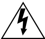
The lightning flash with arrowhead symbol, within an equilateral triangle, is interned to alert the user to the presence of uninsulated "dangerous voltage" within the product's enclosure that may be of sufficient magnitude to constitute a risk of electric shock to persons.

The exclamation point within an equilateral triangle is intended to alert the user to the presence of important operating and maintenance (servicing) instructions in the literature accompanying the appliance.
FOR YOUR SAFETY PLEASE READ THE FOLLOWING TEXT CAREFULLY.
This appliance is supplied with a moulded three pin mains plug for your safety and convenience.
A 5 amp fuse is fitted in this plug.
Should the fuse need to be replaced please ensure that the replacement fuse has a rating of 5 amp and that it is approved by ASTA or BSI to BS1362.
Check for the ASTA mark or the BSI mark on the body of the fuse.
If the plug contains a removable fuse cover you must ensure that it is refitted when the fuse is replaced.
If you lose the fuse cover the plug must not be used until a replacement cover is obtained.
A replacement fuse cover can be purchased from your local Panasonic Dealer.
IF THE FITTED MOULDED PLUG IS UNSUITABLE FOR THE SOCKET OUTLET IN YOUR HOME THEN THE FUSE SHOULD BE REMOVED AND THE PLUG CUT OFF AND DISPOSED OF SAFELY.
THERE IS A DANGER OF SEVERE ELECTRICAL SHOCK IF THE CUT OFF PLUG IS INSERTED INTO ANY 13 AMP SOCKET.
If a new plug is to be fitted please observe the wiring code as shown below.
If in any doubt please consult a qualified electrician.
WARNING: This apparatus must be earthed.
The serial number of this product may be found on the bottom of the unit.
You should note the serial number of this unit in the space provided and retain this book as a permanent record of your purchase to aid identification in the event of theft.
Model No.
Serial No.
WARNING:
TO PREVENT FIRE OR SHOCK HAZARD, DO NOT EXPOSE THIS APPLIANCE TO RAIN OR MOISTURE.
IMPORTANT
The wires in this mains lead are coloured in accordance with the following code.
Green-and-yellow:
Earth
Blue:
Neutral
Brown:
Live
As the colours of the wire in the mains lead of this appliance may not correspond with the coloured markings identifying the terminals in your plug, proceed as follows.
The wire which is coloured green-and-yellow must be connected to the terminal in the plug which is marked with the letter E or by the earth symbol or coloured green or green-and-yellow.
The wire which is coloured blue must be connected to the terminal in the plug which is marked with the letter N or coloured black.
The wire which is coloured brown must be connected to the terminal in the plug which is marked with the letter L or coloured red.
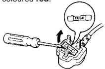
How to replace the fuse
Open the fuse compartment with a screwdriver and replace the fuse and fuse cover.
This model conforms of the EC directive (for radio interference) 87/308/EEC.
This apparatus was produced to BS 800:1987.
For Australia
THIS APPARATUS MUST BE EARTHED.
To ensure safe operation the three-pin plug supplied must be inserted only into a standard three-pin power point which is effectively earthed through the normal household wiring. Extension cords used with the equipment must be three-core and be correctly wired to provide connection to earth. Wrongly wired extension cords are a major cause of fatalities.
The fact that the equipment operates satisfactorily does not imply that the power point is earthed and that the installation is completely safe. For your safety, if in any doubt about the effective earthing of the power point, consult a qualified electrician.
The model numbers listed in this Operating Instructions have no suffixed attached to it.
PREFACE
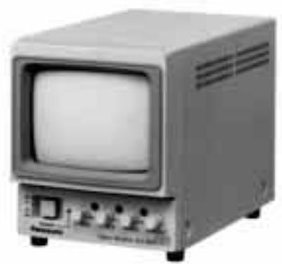
- The Panasonic WV-BM500 is a desk-top closed circuit Video Monitor especially designed for surveillance and studio applications.
WV-BM500 features a 5" screen (diagonal actual visual size) and produces sharp, black-and-white pictures with horizontal resolution of more than 700 lines at center.
Front mounted controls permit fast picture adjustment. Standard BNC-type input and output connectors enables WV-BM500 to be used with other CCTV monitors or Panasonic Video Tape Recorder.
FEATURES
- 5'' screen (diagonal actual visual size).
Horizontal resolution 700 lines at center. - Short H. AFC time constant for VTR playback.
- Bridging input and output connectors for video and composite sync.
- DC restoration.
- Internal and External Sync mode.
- By using the Optional Rack Angle Bracket WVQ64, rack mounting is available.
PRECAUTIONS
- This unit is designed for indoor use. Operable ambient temperature range must not exceed beyond -10^ + 50^ ( 14^ - 122^ ), and permissible humidity is less than 90% . Avoid using the monitor under direct sunlight.
- The input power source is 220 - 240V AC 50 Hz .
- Do not block the ventilation slots on the rear panel and side cover.
- When mounting the Model WV-BM500 in an EIA standard 19^ rack, be careful to insure that the interior temperature of the rack does not exceed +50^ ( 122^ ).
MAJOR OPERATING CONTROLS AND THEIR FUNCTIONS
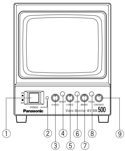
1. Power On/Off Switch (POWER, ON/OFF)
This is a push-push type switch which turns the power of this monitor on and off.
Press once and the switch remains down (—) for turning on the power of monitor.
Press again, the switch comes up (L) for turning off the power of the monitor.
2. Power Indicator (POWER)
By turning on the Power On/Off Switch (1), this indicator lights.
3. Horizontal Hold Control [H-HOLD]
This control is used to Lock in the picture horizontally.
4. Height Control [HEIGHT]
Adjust the vertical height of the picture.
5. Vertical Hold Control [V-HOLD]
This control is used to Lock in the picture vertically.
6. Vertical Linearity Control [V-LIN]
Adjust for vertical distortion of the picture.
7. Bright Control [BRIGHT]
Turn this control clockwise to increase the overall brightness.
8. Focus Control [FOCUS]
Adjust for the clearest picture.
9. Contrast Control [CONTRAST]
Turn this control clockwise to increase the picture contrast .
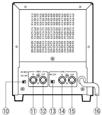
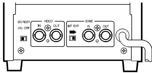
10. DC Restoration Switch [DC REST]
Switch to restore background of picture.
11. Video Input Connector (VIDEO IN)
This connector accepts the input video signal
12. Video Output Connector (VIDEO OUT)
The video input signal connected to the Video Input Connector (11) is looped through to this connector and terminated automatically.
13. Sync Selector Switch [SYNC INT/EXT]
14. Sync Input Connector [SYNC IN]
15. Sync Output Connector [SYNC OUT]
16. AC Power Cord
OPERATING PROCEDURE
- Set the Power On/Off Switch (1) to the ON ( ) position.
- Adjust the Bright Control (7) and Contrast Control (9).

increase

increase
BRIGHT
CONTRAST
- Adjust the Horizontal Hold (3) until the picture is stabilized, if the picture slips to either side, or appears as a series of horizontal stripes.
- Adjust the Vertical Hold (5), if the picture rolls up or down.

H.HOLD

V.HOLD
- Height (4)
This recessed screwdriver control should be adjusted simultaneously to give proper vertical height consistent with good vertical linearity. Adjustment should be made to extend the picture limits approximately 1/10 beyond the top and bottom edges of the mask at over scanning operation.
- Vertical Linearity (6)
This recessed screwdriver control should be adjusted to give proper vertical linearity.
- Focus (8)
The clearest picture is produced when this screwdriver control is adjusted.
- DC Restoration (10)
DC restoration circuit provides a stable reference for the black level. Set the switch to ON position to prevent excessive contrast and preserve shadow detail.
INSTALLATION
CAUTION:
The following installation should be made by qualified service personnel or system installers.
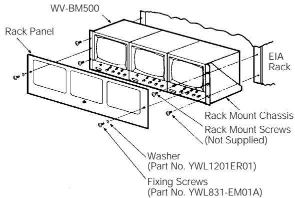
Mounting into EIA Standard 19" Rack
Model WV-BM500 can be mounted into EIA 19" rack as shown below.
Note: Rack Mounting requires the purchase of optional WV-Q64 Rack Angle Bracket.
CONNECTIONS
Power Cable
- Keep the camera Power switched OFF during installation.
- Connect the Power Cord (16) to a 50Hz grounded electrical outlet 220-240V AC.
Video Cable
- Use the RG-59/U (3C-2V), RG-6/U (5C-2V). RG-11/U (7C-2V) or RG-15/U (10C-2V) coaxial cable.
- Up to 10 monitors can be hooked up in this configuration before signal loss occurs. Total cable length should not exceed 500 feet (150m).
-
Wiring Precautions
-
Do not bend coaxial cable into a curve whose radius is smaller than 10 times of its diameter.
- Never crush or pinch the cable All these will change the impedance of the cable and cause poor picture quality
Recommended maximum cable length
| Cable | RG-59/U(3C-2V) | RG-6U(5C-2V) | RG-11/U(7C-2V) | RG-15/U(10C-2V) | |
| Recommended maximum cable length | (m) | 500 | 750 | 1000 | 1250 |
| (ft) | 1650 | 2475 | 3300 | 4125 | |
External Sync
When a non-composite video signal is connected to the monitor, it will be necessary to connect an external composite sync signal to the monitor.
- Connect the Sync Input Connector (14) on the video monitor to the sync signal source by means of a 75 coaxial cable.
- Set the Sync Selector Switch (13) at EXT position.
NOTE:
- Non-composite video signal is a signal without sync.
- External sync should be composed of mixed H. Sync and V. sync signals, not H. and V. drive pulse signals. Composite Sync Level: 4.0 Vp-p (2.0 Vp-p - 5.0 Vp-p)
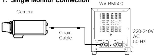
SYSTEM CONNECTION
1. Single Monitor Connection
2. Multiple Monitor Connection
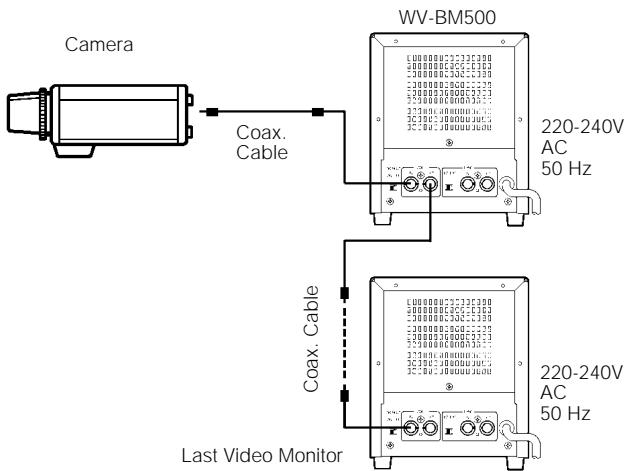
Internal Sync Connection
- Connect the Video Input Connector (11) on the monitor to the Video Out Terminal of cameras with 75-ohm coaxial cables.
External Sync Connection
- When a non-composite video signal is connected to the video monitor, it must also have an external composite SYNC signal connected to the video monitor.
- Set the Sync Selector Switch (13) at EXT position.
- Loop through connection of sync signal is the same as the case of Video Signal.
SPECIFICATIONS
| Power Source : | WV-BM500/A, WV-BM500/B, WV-BM500/G: 220-240V AC50Hz |
| Power Consumption : | Approx. 14W |
| Tube Size : | 5" diagonal actual visual size |
| Video Input Impedance : | 75Ω or high impedance (Auto Termination) |
| Video Input Level : | 1.0 Vp-p composite (0.5 Vp-p - 2.0 Vp-p) |
| Resolution : | More than 700 lines (Horizontal at center) |
| Scanning Frequency : | Horizontal : 15.625kHz |
| Vertical : 50Hz | |
| Sweep Linearity : | Horizontal : Less than 5% |
| Vertical : Less than 5% | |
| External Sync Input Impedance : | 75Ω or high impedance (Auto Termination) |
| External Sync Input Level : | 4.0 Vp-p negative (2.0 Vp-p - 5.0 Vp-p) |
| Operating Ambient Temperature : | -10°C - +50°C (14°F - 122°F) |
| Operating Ambient Humidity : | Less than 90 % |
| Dimensions : | 147 (W) x 180 (H) x 245 (D) mm |
| [5-13/16" (W) x 7-1/16" (H) x 9-5/8" (D)] | |
| Weight : | 2.3 kg [5.1 lbs] |
Weight and dimension indicated above are approximate.
Specifications are subject to change without notice.
OPTIONAL ACCESSORY
Rack Angle Bracket WV-Q64
Matsushita Electric Industrial Co., Ltd.
Central P.O. Box 288, Osaka 530-91, Japan
N0194-0
YWV8QA3285AN
N 13
Printed in Japan
Gedruckt in Japan
Imprimé au Japon
- Operating Instructions
- Panasonic
- ENGLISH VERSION
- CAUTION
- CAUTION:
- FOR YOUR SAFETY PLEASE READ THE FOLLOWING TEXT CAREFULLY.
- IF THE FITTED MOULDED PLUG IS UNSUITABLE FOR THE SOCKET OUTLET IN YOUR HOME THEN THE FUSE SHOULD BE REMOVED AND THE PLUG CUT OFF AND DISPOSED OF SAFELY.
- THERE IS A DANGER OF SEVERE ELECTRICAL SHOCK IF THE CUT OFF PLUG IS INSERTED INTO ANY 13 AMP SOCKET.
- IMPORTANT
- How to replace the fuse
- For Australia
- THIS APPARATUS MUST BE EARTHED.
- PREFACE
- FEATURES
- PRECAUTIONS
- MAJOR OPERATING CONTROLS AND THEIR FUNCTIONS
- Power On/Off Switch (POWER, ON/OFF)
- Power Indicator (POWER)
- Horizontal Hold Control [H-HOLD]
- Height Control [HEIGHT]
- Vertical Hold Control [V-HOLD]
- Vertical Linearity Control [V-LIN]
- Bright Control [BRIGHT]
- Focus Control [FOCUS]
- Contrast Control [CONTRAST]
- DC Restoration Switch [DC REST]
- Video Input Connector (VIDEO IN)
- Video Output Connector (VIDEO OUT)
- Sync Selector Switch [SYNC INT/EXT]
- Sync Input Connector [SYNC IN]
- Sync Output Connector [SYNC OUT]
- AC Power Cord
- OPERATING PROCEDURE
- BRIGHT
- CONTRAST
- INSTALLATION
- Mounting into EIA Standard 19" Rack
- CONNECTIONS
- Power Cable
- Video Cable
- External Sync
- NOTE:
- SYSTEM CONNECTION
- Single Monitor Connection
- Multiple Monitor Connection
- Internal Sync Connection
- External Sync Connection
- SPECIFICATIONS
- OPTIONAL ACCESSORY
- Matsushita Electric Industrial Co., Ltd.
Brand : PANASONIC
Model : WVBM500
Category : Video monitor