DS-K1103 - Memory reader Hikvision - Free user manual and instructions
Find the device manual for free DS-K1103 Hikvision in PDF.

| Product Type | Proximity Card Reader with Keypad |
| Dimensions (H x W x D) | 119 mm x 75 mm x 21 mm |
| Weight | 150 g |
| Power Supply | 12 V DC, 100 mA max |
| Reading Frequency | 13.56 MHz (MIFARE) or 125 kHz (EM) |
| Read Range | Up to 50 mm (MIFARE), up to 80 mm (EM) |
| Keypad | 12-key backlit keypad (0-9, *, #) |
| Communication Interface | Wiegand 26/34-bit or RS-485 |
| LED Indicators | Bi-color (red/green) for status |
| Buzzer | Built-in for audible feedback |
| Tamper Switch | Yes, anti-tamper detection |
| Operating Temperature | -20 °C to 65 °C |
| Operating Humidity | 10% to 90% RH (non-condensing) |
| Housing Material | Polycarbonate (UV resistant) |
| Protection Rating | IP65 (weatherproof) |
| Mounting Type | Surface mount on standard gang box |
| Cable Length | Pre-wired with 3 m pigtail cable |
| Compatibility | Hikvision access controllers and third-party panels |
| Functions | Card reading, PIN input, card+PIN modes |
| Maintenance | Clean with a soft dry cloth; avoid liquids |
| Safety | CE, FCC, RoHS compliant |
| Repairability | Replaceable cable and tamper switch; no user-serviceable parts |
Frequently Asked Questions - DS-K1103 Hikvision
User questions about DS-K1103 Hikvision
0 question about this device. Answer the ones you know or ask your own.
Ask a new question about this device
Download the instructions for your Memory reader in PDF format for free! Find your manual DS-K1103 - Hikvision and take your electronic device back in hand. On this page are published all the documents necessary for the use of your device. DS-K1103 by Hikvision.
USER MANUAL DS-K1103 Hikvision
DS-K1100 Series Card Reader User Manual
User Manual
© 2018 Hangzhou Hikvision Digital Technology Co., Ltd.
ALL RIGHTS RESERVED.
Any and all informaon, including, among others, wordings, pictures, graphs are the properes of Hangzhou Hikvision Digital Technology Co., Ltd. or its subsidiaries (hereinaer referred to be “Hikvision”). This user manual (hereinaer referred to be “the Manual”) cannot be reproduced, changed, translated, or distributed, parally or wholly, by any means, without the prior written permission of Hikvision. Unless otherwise spulated, Hikvision does not make any warranes, guarantees or representaons, express or implied, regarding to the Manual.
This Manual is applicable to card reader.
| Series | Models | Descripon |
| DS-K1101 Series | DS-K1101M | MIFARE card reader (without keypad) |
| DS-K1101MK | MIFARE card reader (with a keypad) | |
| DS-K1101C | CPU card reader (without keypad) | |
| DS-K1101CK | CPU card reader (with a keypad) | |
| DS-K1102 Series | DS-K1102M | MIFARE card reader (without keypad) |
| DS-K1102MK | MIFARE card reader (with a keypad) | |
| DS-K1102C | CPU card reader (without keypad) | |
| DS-K1102CK | CPU card reader (with a keypad) | |
| DS-K1102E | EM card reader (without keypad) | |
| DS-K1102 EK | EM card reader (with a keypad) | |
| DS-K1102 EM | Dual-band card reader(without keypad) | |
| DS-K1102 EMK | Dual-band card reader(with a keypad) | |
| DS-K1103 Series | DS-K1103M | MIFARE card reader (without keypad) |
| DS-K1103MK | MIFARE card reader (with a keypad) | |
| DS-K1103C | CPU card reader (without keypad) | |
| DS-K1103CK | CPU card reader (with a keypad) | |
| DS-K1104 Series | DS-K1104M | MIFARE card reader (without keypad) |
| DS-K1104MK | MIFARE card reader (with a keypad) | |
| DS-K1104C | CPU card reader (without keypad) | |
| DS-K1104CK | CPU card reader (with a keypad) |
About this Manual
This Manual is subject to domesc and internaonal copyright protecon. Hangzhou Hikvision Digital Technology Co., Ltd. ("Hikvision") reserves all
rights to this manual. This manual cannot be reproduced, changed, translated, or distributed, parally or wholly, by any means, without the prior written permission of Hikvision.
Trademarks
HIKVISION and other Hikvision's trademarks and logos are the properes of Hikvision in various jurisdicons. Other trademarks and logos menoned below are the properes of their respective owners.
Legal Disclaimer
TO THE MAXIMUM EXTENT PERMITTED BY APPLICABLE LAW, THE PRODUCT DESCRIBED, WITH ITS HARDWARE, SOFTWARE AND FIRMWARE, IS PROVIDED "AS IS", WITH ALL FAULTS AND ERRORS, AND HIKVISION MAKES NO WARRANTIES, EXPRESS OR IMPLIED, INCLUDING WITHOUT LIMITATION, MERCHANTABILITY, SATISFACTORY QUALITY, FITNESS FOR A PARTICULAR PURPOSE, AND NON-INFRINGEMENT OF THIRD PARTY. IN NO EVENT WILL HIKVISION, ITS DIRECTORS, OFFICERS, EMPLOYEES, OR AGENTS BE LIABLE TO YOU FOR ANY SPECIAL, CONSEQUENTIAL, INCIDENTAL, OR INDIRECT DAMAGES, INCLUDING, AMONG OTHERS, DAMAGES FOR LOSS OF BUSINESS PROFITS, BUSINESS INTERRUPTION, OR LOSS OF DATA OR DOCUMENTATION, IN CONNECTION WITH THE USE OF THIS PRODUCT, EVEN IF HIKVISION HAS BEEN ADVISED OF THE POSSIBILITY OF SUCH DAMAGES.
REGARDING TO THE PRODUCT WITH INTERNET ACCESS, THE USE OF PRODUCT SHALL BE WHOLLY AT YOUR OWN RISKS. HIKVISION SHALL NOT TAKE ANY RESPONSIBILITIES FOR ABNORMAL OPERATION, PRIVACY LEAKAGE OR OTHER DAMAGES RESULTING FROM CYBER ATTACK, HACKER ATTACK, VIRUS INSPECTION, OR OTHER INTERNET SECURITY RISKS; HOWEVER, HIKVISION WILL PROVIDE TIMELY TECHNICAL SUPPORT IF REQUIRED.
SURVEILLANCE LAWS VARY BY JURISDICTION. PLEASE CHECK ALL RELEVANT LAWS IN YOUR JURISDICTION BEFORE USING THIS PRODUCT IN ORDER TO ENSURE THAT YOUR USE CONFORMS THE APPLICABLE LAW. HIKVISION SHALL NOT BE LIABLE IN THE EVENT THAT THIS PRODUCT IS USED WITH ILLEGITIMATE PURPOSES.
IN THE EVENT OF ANY CONFLICTS BETWEEN THIS MANUAL AND THE APPLICABLE LAW, THE LATER PREVAILS.
Regulatory Informaon
Please take aenon that changes or modicaon not expressly approved by the party responsible for compliance could void the user's authority to operate the equipment.
FCC compliance: This equipment has been tested and found to comply with the limits for a Class A digital device, pursuant to part 15 of the FCC Rules. These limits are designed to provide reasonable protecon against harmful interference when the equipment is operated in a commercial environment. This equipment generates, uses, and can radiate radio frequency energy and, if not installed and used in accordance with the instrucon manual, may cause harmful interference to radio communicaons. Operaon of this equipment in a residential area is likely to cause harmful interference in which case the user will be required to correct the interference at his own expense.
FCC Conditions
This device complies with part 15 of the FCC Rules. Operaon is subject to the following two conditions:
- This device may not cause harmful interference.
- This device must accept any interference received, including interference that may cause undesired operaon.
EU Conformity Statement

This product and - if applicable - the supplied accessories too are marked with "CE" and comply therefore with the applicable harmonized European standards listed under the RE Direcve 2014/53/EU, the EMC Direcve
2014/30/EU, the LVD Direcve 2014/35/EU, the RoHS Direcve 2011/65/EU.

natural_image
Symbol of a trash bin crossed with a diagonal line and a horizontal bar below (no text or numbers present)2012/19/EU (WEEE direcve): Products marked with this symbol cannot be disposed of as unsorted municipal waste in the European Union. For proper recycling, return this product to your local supplier upon the purchase of equivalent new equipment, or dispose of it at designated collecon points. For more informaon see: www.recyclethis.info.

natural_image
Symbol of a trash bin crossed with two crossed lines, representing no waste or elimination (no text or labels)2006/66/EC (baery direcve): This product contains a baery that cannot be disposed of as unsorted municipal waste in the European Union. See the product documentaon for specic baery informaon. The baery is marked with this symbol, which may include leering to indicate cadmium (Cd), lead (Pb), or mercury (Hg).
For proper recycling, return the baery to your supplier or to a designated collecon point. For more informaon see: www.recyclethis.info.
Industry Canada ICES-003 Compliance
This device meets the CAN ICES-3 (A)/NMB-3(A) standards requirements.
Use only power supplies listed in the user instrucons:
| Model | Manufacturer | Standard |
| TS-A018-120015Ec | Shenzhen TransinTechnologies Co., Ltd | CEE |
Safety Instrucon
These instrucons are intended to ensure that user can use the product correctly to avoid danger or property loss.
The precauon measure is divided into Warnings and Cauons:
Warnings: Neglecng any of the warnings may cause serious injury or death.
Cauons: Neglecng any of the cauons may cause injury or equipment damage.
 |  |
| Warnings Follow these safeguards to prevent serious injury or death. | Cauons Follow these precautions to prevent potential injury or material damage. |
Warnings
- All the electronic operaon should be strictly compliance with the electrical safety regulaons, re prevenon regulaons and other related regulaons in your local region.
- Please use the power adapter, which is provided by normal company. The power consumpon cannot be less than the required value.
- Do not connect several devices to one power adapter as adapter overload may cause over-heat or re hazard.
- Please make sure that the power has been disconnected before you wire, install or dismantle the device.
- When the product is installed on wall or ceiling, the device shall be rmly xed.
- If smoke, odors or noise rise from the device, turn o the power at once and unplug the power cable, and then please contact the service center.
- If the product does not work properly, please contact your dealer or the nearest service center. Never aempt to disassemble the device yourself. (We shall not assume any responsibility for problems caused by unauthorized repair or maintenance.)

Cauons
- Do not drop the device or subject it to physical shock, and do not expose it to high electromagnesm radiaon. Avoid the equipment installaon on
vibraons surface or places subject to shock (ignorance can cause equipment damage).
- Do not place the device in extremely hot (refer to the specicaon of the device for the detailed operang temperature), cold, dusty or damp locaons, and do not expose it to high electromagnec radiaon. The appropriate temperature is -20^ to 65^ .
● The device cover for indoor use shall be kept from rain and moisture.
- Exposing the equipment to direct sun light, low venlaon or heat source such as heater or radiator is forbidden (ignorance can cause re danger).
- Do not aim the device at the sun or extra bright places. A blooming or smear may occur otherwise (which is not a malfuncon however), and aecng the endurance of sensor at the same me.
- Please use the provided glove when open up the device cover, avoid direct contact with the device cover, because the acidic sweat of the ngers may erode the surface coang of the device cover.
- Please use a so and dry cloth when clean inside and outside surfaces of the device cover, do not use alkaline detergents.
- Please keep all wrappers aer unpack them for future use. In case of any failure occurred, you need to return the device to the factory with the original wrapper. Transportaon without the original wrapper may result in damage on the device and lead to additional costs.
- Improper use or replacement of the baery may result in hazard of explosion. Replace with the same or equivalent type only. Dispose of used baeries according to the instrucons provided by the baery manufacturer.
Prevenve and Cauonary Tips
To guarantee the card reader works properly, please read and obey the notes below.
- If the card reader is powered by the controller, the power supply distance is recommended to be no longer than 100m. If the distance is longer than 100m, you are advised to power the card reader by external 12V (range: -%10 \~ +%10) DC power supply, which is nonswitched and linear.
● To guarantee the communicaon between the controller and the card
reader, you must use RVVP cable above 0.5 to connect them.
- If the card reader is installed outside or in environment easy to permeable, it is advisable to install a waterproof shield.
- If you need to install several card readers, the distance among them must over 30cm.
- To reduce the noise in long distance transmission, the shield of cable should connect to the GND of both controller and card reader terminal.
Content
Chapter 1 Introducon....1
1.1 Front View....1
1.2 Rear View....3
1.3 Slide View....5
Chapter 2 Installaon....7
2.1 Installing PSAM Card 7
2.2 Introducon for DIP Switch 7
2.3 Denion of Cable....8
2.4 Wiring Cables....9
2.5 Installing Card Reader....11
Chapter 3 Sound Prompt and Indicator.... 13
Chapter 1 Introduction
DS-K1100 series card reader is a kind of high-performance product, with a 32 bit high-speed processor. It communicates with access controller via either RS-485 protocol or Wiegand protocol. And a build-in tamper-proof module helps to protect card reader from malicious damage. As to the physical appearance, the PC+ABS material makes water proof and dust proof possible in poor environment.
1.1 Front View
The front view of DS-K1101 series card reader is shown below:
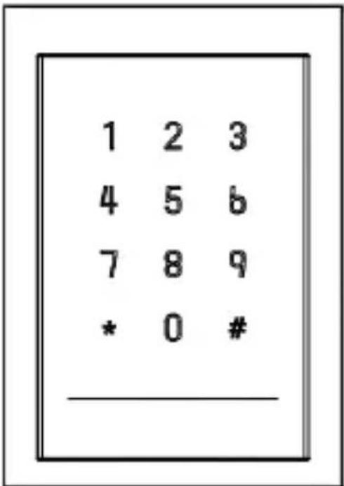
Figure 1-1 DS-K1101MK/DS-K1101CK
natural_image
Line drawing of a smartphone with a wireless signal icon on the screen (no text or symbols)Figure 1-2 DS-K1101M/DS-K1101C
The front view of DS-K1102 series card reader is shown below:
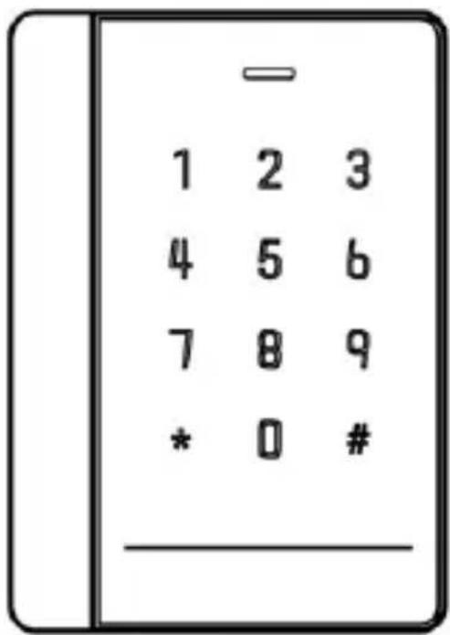
Figure 1-3 DS-K1102MK/DS-K1102CK
natural_image
Simple line drawing of a smartphone with a diamond-shaped tag and wireless signal icon (no text or symbols)Figure 1-4 DS-K1102M/DS-K1102C
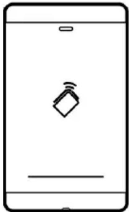
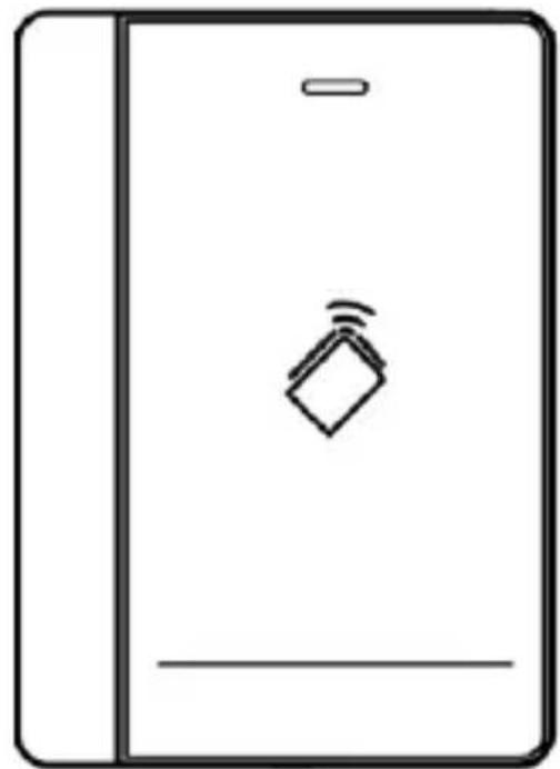
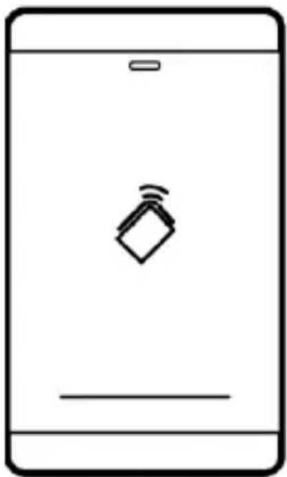
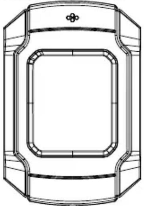
The front view of DS-K1103 series card reader is shown below:
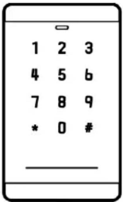
Figure 1-5 DS-K1103MK/DS-K1103CK
natural_image
Simple line drawing of a smartphone with a speech bubble icon on the screen (no text or symbols)Figure 1-6 DS-K1103M/DS-K1103C
The front view of DS-K1104 series card reader is shown below:
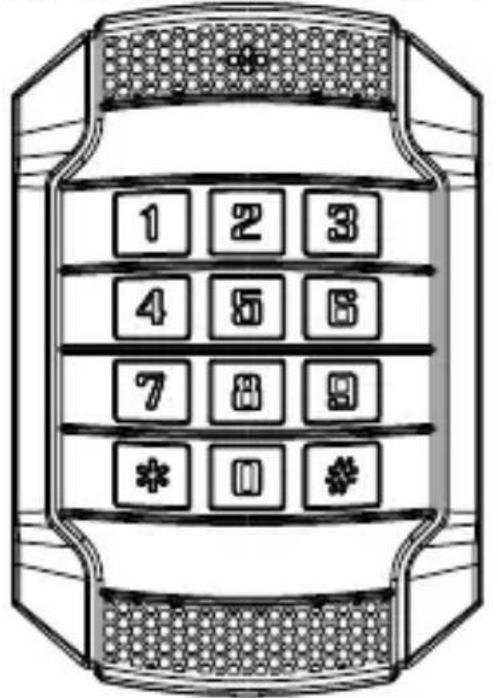
Figure 1-7 DS-K1104MK/DS-K1104CK
natural_image
Technical line drawing of a rectangular device with rounded corners and a central square frame (no text or symbols)Figure 1-8 DS-K1104M/DS-K1104C
1.2 Rear View
The rear view of card reader is shown below:
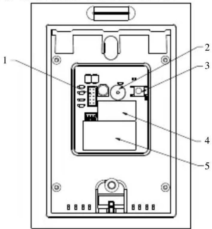
Figure 1-9 Rear View of DS-K1101 Series
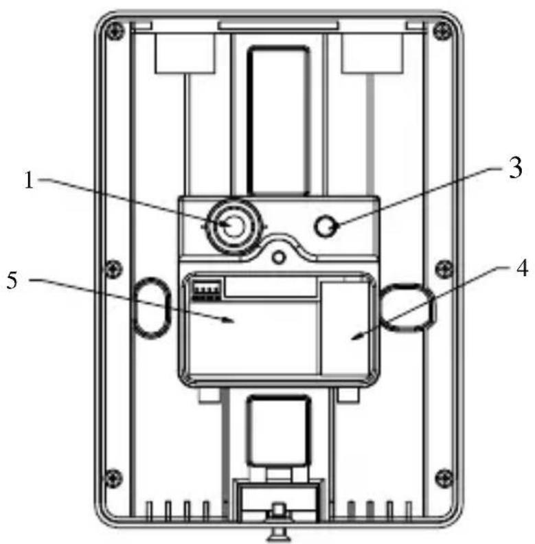
Figure 1-10 Rear View of DS-K1102 Series
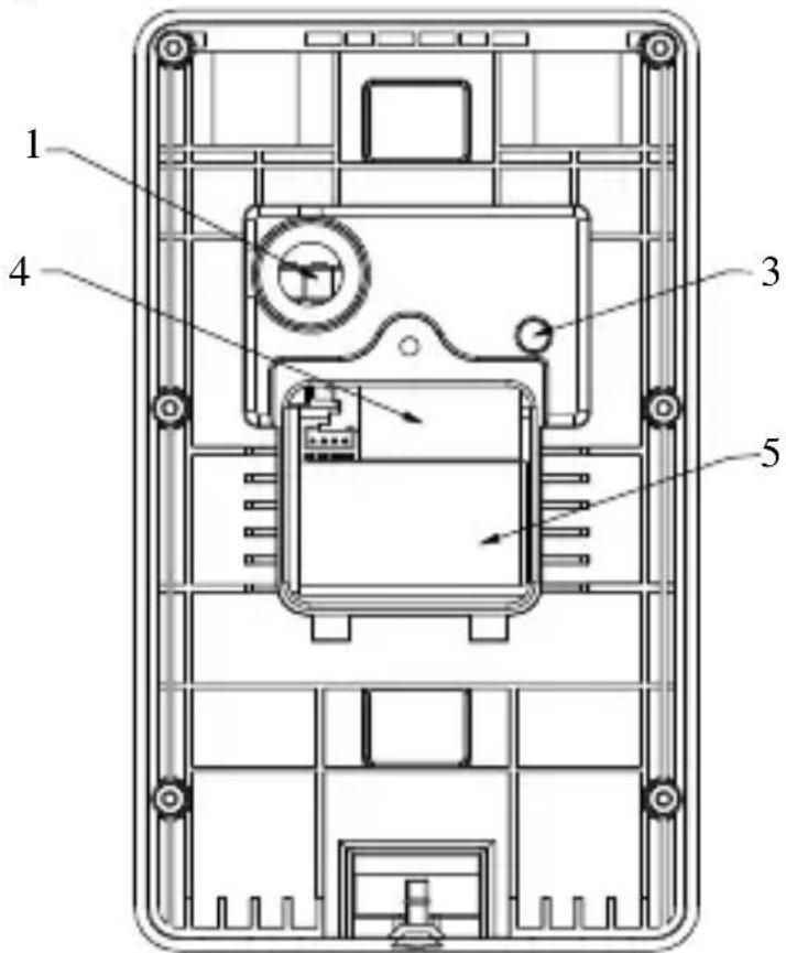
Figure 1-11 Rear View of DS-K1103 Series
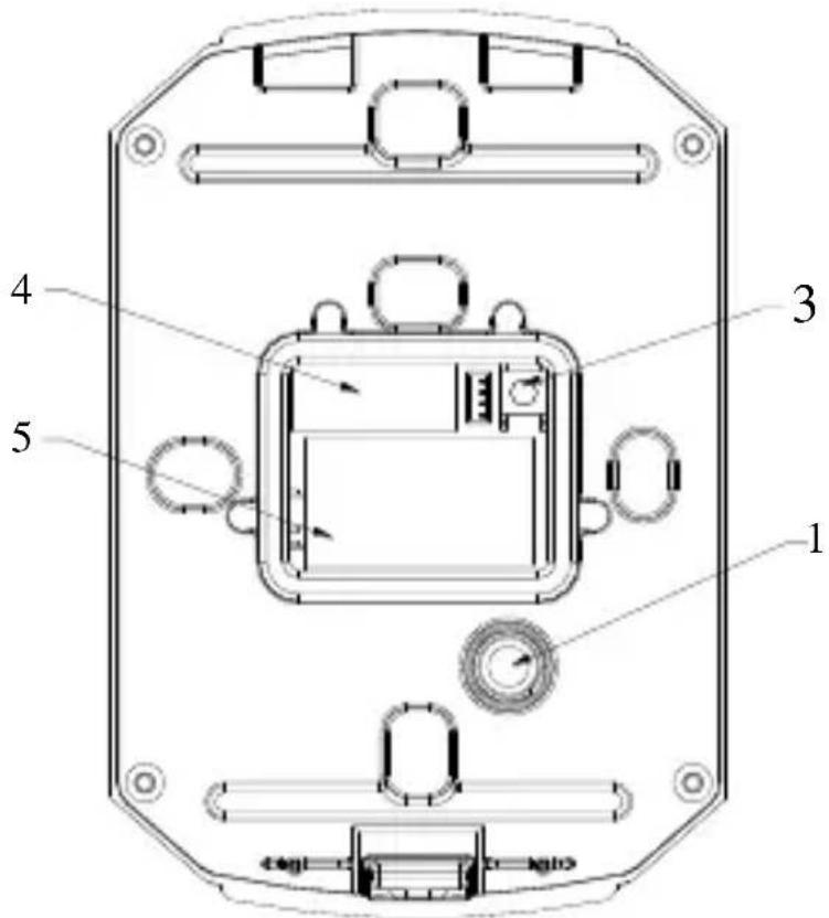
Figure 1-12 Rear View of DS-K1104 Series
Table 1-1 Descripon of Rear View
| No. | Name |
| 1 | Cable Interface of RS-485, Power, LED Control, etc. |
| 2 | Buzzer |
| 3 | Tamper-proof Module |
| 4 | DIP Switch |
| 5 | PSAM Card Slot (available for CPU card reader) |
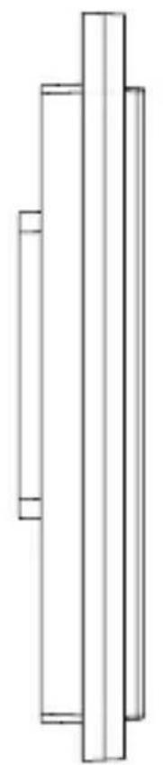
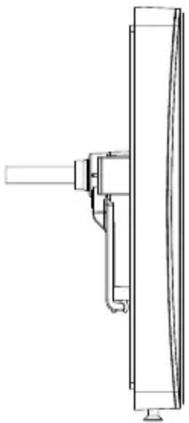
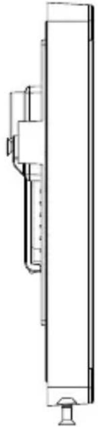
1.3 Slide View
The side view of card reader is shown below:
natural_image
Pure mechanical part diagram showing two vertical columns with no text or symbolsFigure 1-13 DS-K1101 Series
natural_image
Technical line drawing of a mechanical assembly or bracket component (no text or symbols)Figure 1-14 DS-K1102 Series
natural_image
Technical line drawing of a vertical mechanical or electrical component with no visible text or symbolsFigure 1-15 DS-K1103 Series
natural_image
Technical line drawing of a door frame with handle and side panels (no text or symbols)Figure 1-16 DS-K1104 Series
Chapter 2 Installation
2.1 Installing PSAM Card

PSAM card slot is only available for CPU card reader. Insert the PSAM card into the slot according to the direcon shown below.
natural_image
Pure electrical circuit lines without any symbolsFigure 2-1 PSAM Card Slot
2.2 Introducon for DIP Switch
The DIP switch module is shown below. The No. of DIP switch from le to right is 1 \~ 8.
Figure 2-2 DIP Switch Module
Table 2-1 Descripon of DIP Switch
| Icon | Descripon |
 | Represent 1 in binary mode |
| [7GDS] | Represent 0 in binary mode |
For example, binary value of the following status is: 0000 1100.
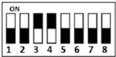
Figure 2-3 DIP Switch Module
Table 2-2 Descripon of DIP Switch
| No. | Descripon | DIP Switch Status |
| 1 ~ 4 | Address of RS-485 | 1: 10: 0 |
| 5 | Read card No. or le in card. (Only available for CPU card reader.) | 1: read card No;0: read le in card. |
| 6 | Wiegand protocol or RS-485 protocol. | 1: Wiegand protocol;0: RS-485 protocol. |
| 7 | Wiegand Protocol (available when No. 6 is 1) | 1: Wiegand protocol of 26-bit;0: Wiegand protocol of 34-bit. |
| 8 | Matched Resistance (available for RS-485 protocol) | 1: Enable;0: Disable. |
2.3 Denion of Cable
The descripon of 10 cables is shown below.
Table 2-3 Descripon of Cable
| Color | Descripon |
| Yellow | RS-485+ |
| Brown | Blue LED Control (available for Wiegand Protocol) |
| Blue | RS-485- |
| Purple | Beep Control (available for Wiegand Protocol) |
| Gray | Case Sensor (available for Wiegand Protocol) |
| Green | Wiegand W0 (available for Wiegand Protocol) |
| White | Wiegand W1 (available for Wiegand Protocol) |
| Black | GND |
| Orange | Red LED Control (available for Wiegand Protocol) |
| Red | PWR (DC +12V) |
2.4 Wiring Cables
Purpose:
Wire the cables between controller and card reader, thus to establish the communicaon between them.
Steps for RS-485 communicaon mode:
- Set the DIP switch of No. 6 as 0.
- Set the DIP switch of No. 1 \~ 5 for RS-485 address and reading card mode. For details, please refer to 2.2 Introducon for DIP Switch.
- Wire the cable between controller and card reader as shown below.
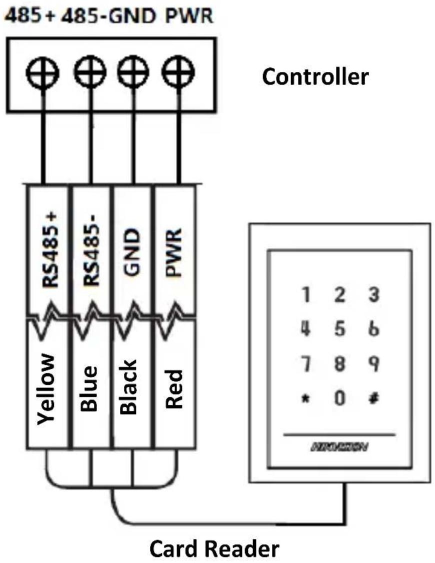
Figure 2-4 Wiring for RS-485 Communicaton Mode
Steps for Wiegand communicaon mode:
- Set the DIP switch of No. 6 as 1.
- Set the DIP switch of No. 5 and 7 for reading card mode and Wiegand protocol. For details, please refer to 2.2 Introducon for DIP Switch.
- Wiring the cable between controller and card reader as shown below.
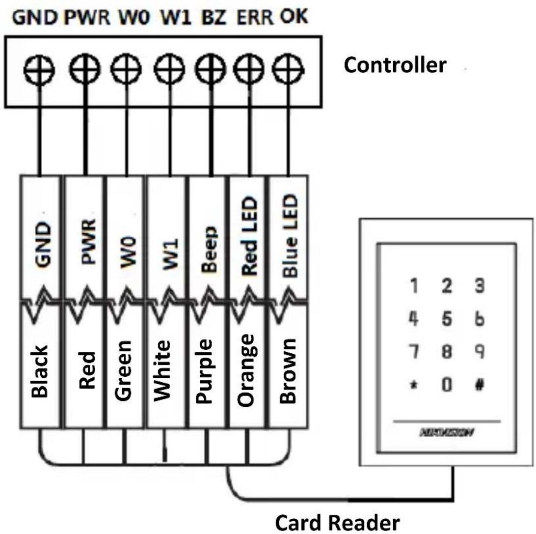
Figure 2-5 Wiring for Wiegand Communicaon Mode
2.5 Installing Card Reader
Before you start:
Set the DIP switch. For details, refer to 2.2 Introducon for DIP Switch.
Steps:
- Fix the gang box on the wall or other place.
- Connect the cables between controller and card reader. For details, refer to 2.4 Wiring Cables.
- Push the card reader to match the xed gang box.
- Fasten the screw to keep the components together.
- Fix the side cover onto the card reader, press the cover to make it ghtly t the reader.
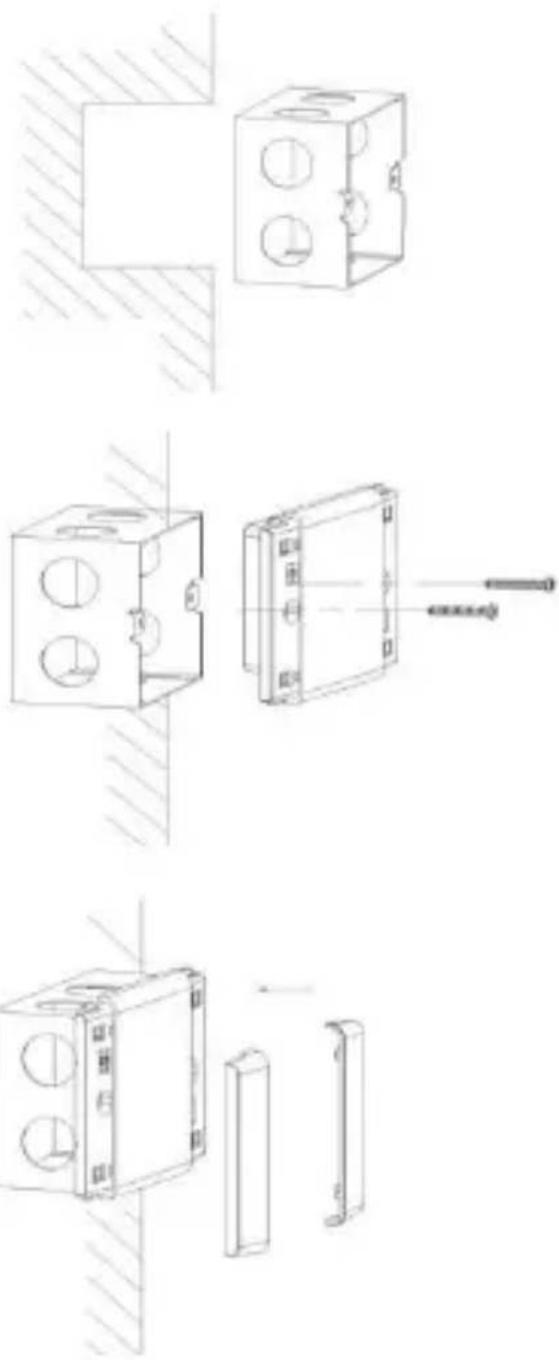
natural_image
Technical line drawing of a mechanical assembly with three circular holes and a shaft, shown in three sequential steps (no text or symbols)Chapter 3 Sound Prompt and Indicator
Aer the card reader is powered on, LED status indicator will turn blue and blink for 1 me. Then it will turn red and blink for 3 mes. At last the buzzer will send out a beep sound indicang the starng up process is completed.
During using the card reader, it will send out dierent sounds prompt and the LED indicator on it have dierent statuses. You can refer to tables below for detailed informaon.
Table 3-1 Descripon of Prompt Sound
| Sound Prompt | Descripon |
| One beep | RS-485 protocol: Pressing keys prompt; Swiping card prompt; Time out prompt for pressing keys or swiping card.Wiegand protocol: Pressing keys prompt; Swiping card prompt. |
| Two rapid beeps | The operaon of pressing keys or swiping card is valid. |
| Three slow beeps | The operaon of pressing keys or swiping card is invalid. |
| Rapidly connuous beeps | Alarm of tamper-proof. |
| Slowly connuous beeps | The card reader is unencrypted. |
Table 3-2 Descripon of LED Indicator
| LED Indicator Status | Descripon |
| Green and blinking | Card reader is working normally. |
| Solid green | The operaon of pressing keys or swipingcard is valid. |
| Solid red | The operaon of pressing keys or swiping card is invalid. |
| Red and blinking | For RS-485 protocol: Registering failed or card reader is oine. Failed to get key les of PSAM card; Failed to detect the PSAM card. |
| Red and Keeping rapidly blinking | Available for reading le mode of CPU card: PSAM is not inserted or undetected. |
020000001081030

See Far, Go Further