
TP7 - Controller Niles - Free user manual and instructions
Find the device manual for free TP7 Niles in PDF.


| Product Type | Controller |
| Brand | Niles |
| Model | TP7 |
| Dimensions (approx) | 4.5 x 2.5 x 1.2 inches |
| Weight | 0.5 lbs |
| Power Supply | 12V DC |
| Primary Functions | Audio/video source selection, volume control, IR routing, RS-232 control |
| Control Interfaces | Infrared (IR), RS-232, possibly Ethernet |
| Compatibility | Niles audio/video systems and third-party components via IR |
| Mounting | Wall-mountable, in-wall or surface |
| Display Type | Backlit LCD touchscreen (typical) |
| Maintenance & Cleaning | Wipe with a soft, dry cloth; avoid liquids and abrasives |
| Safety | Low voltage device; follow local electrical codes for installation |
| Spare Parts & Repairability | Contact Niles customer support for spare parts and service information |
| General Information | Designed for whole-home audio distribution; programming may require dealer assistance |
Frequently Asked Questions - TP7 Niles
User questions about TP7 Niles
0 question about this device. Answer the ones you know or ask your own.
Ask a new question about this device
Download the instructions for your Controller in PDF format for free! Find your manual TP7 - Niles and take your electronic device back in hand. On this page are published all the documents necessary for the use of your device. TP7 by Niles.
USER MANUAL TP7 Niles
TP7 – 7" Touch Panel
User Interface
Quick Install Guide
English
TP7 – Overview

flowchart
graph TD
    A["Speaker"] --> B["Status LED"]
    B --> C["Proximity Sensor"]
    C --> D["Microphone"]
    D --> E["Camera"]
    E --> F["Power"]
    style A fill:#f9f,stroke:#333
    style B fill:#ccf,stroke:#333
    style C fill:#cfc,stroke:#333
    style D fill:#fcc,stroke:#333
    style E fill:#cff,stroke:#333
    style F fill:#ffc,stroke:#333

Planning the installation
The TP7 is designed to wall mount in either Portrait or Landscape orientation.
Ensure there is adequate wall space for the TP7 and that the surface is relatively smooth.
The TP7 requires a minimum mounting depth of 1 34 (4.5 cm) from the front surface plus room for wire. Ensure that adequate depth is available.
Power may be supplied by Power Over Ethernet (PoE) or by a 12v DC power supply (not included).
PoE must meet the IEEE 802.3af standard. Direct power via a 12v DC external power supply requires a minimum current output of 1A.
The TP7 connects to the local network via Ethernet or Wi-Fi. When utilizing Wi-Fi you must ensure that there is adequate Wi-Fi coverage at the mounting location.
1 Installing the TP7
a. Mounting height
- Depending on how tall your homeowner is, it is recommended to locate the center of TP 7 between 57"-65" (145 cm -165 cm) above the finished floor.

b. Rough-In
The TP7 has been designed to mount to a US standard 2 gang box or low voltage bracket.
- The TP7 is "snap" fit into the box/bracket and requires approximately 10lbs of force to remove it from the wall. Ensure that the mounting method you are using is compatible with these requirements.

natural_image
Exterior view of a gray metal enclosure with internal components and mounting bracket (no text or symbols)New Const. Box

natural_image
Exterior view of a gray industrial electrical enclosure with internal components (no visible text or symbols)Old Work Box

natural_image
Metal bracket with mounting holes and a triangular support (no text or symbols visible)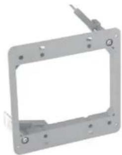
natural_image
Metal frame with mounting holes and a small protrusion (no text or symbols)New Const. Low Volt Bracket Old Work Low Volt Bracket
c. Landscape Mounting
- Install the 2 gang box or bracket in it's normal orientation – with mounting screw holes at the top and bottom. The box is exactly centered with the touch panel for your convenience.

d. Portrait Mounting
- Install the 2 gang box or bracket rotated 90^ - with the mounting screw holes on the left and right sides. The box is exactly centered in the touch panel for your convenience.

e. Installing the TP7 Bracket
- The TP7 includes a mounting bracket that MUST be used. Using the included screws mount the bracket onto the 2 gang box or low voltage bracket and verify that the bracket is level before tightening the screws.
- The mounting bracket is designed to level out uneven wall surfaces allowing the TP7 to fit securely on most any surface. Note that uneven surfaces will create a gap between the back of the panel and the wall – this is normal. Do not tighten the mounting bracket so as to distort it's shape as this will create issues with properly seating the TP7 in the bracket.

natural_image
Technical line drawing showing two views of a device with labeled components and alignment arrows (no text or symbols)f. Connecting the TP7 to power
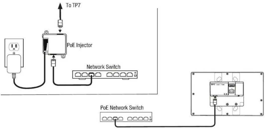
- The TP7 is designed to be powered over the Ethernet connection (PoE) or by connecting a 12v power supply (not included), but not both. If both the PoE and a 12v power supply are connected the TP7 will draw power from the 12v source.
PoE Connection
- PoE connection requires that IEEE 802.3af standard (13w maximum draw @48 V==@270 mA) is met. Utilize a network switch or PoE injector that meets this standard.
- Connect the TP7 using a standard T568A or T568B Ethernet cable from the network switch to the LAN/PoE jack. If you have terminated your own CAT 5e/6/7 cable use a tester to ensure that both ends have been properly terminated.
flowchart
graph TD
    A["Power Input"] --> B["PoE Injector"]
    B --> C["Network Switch"]
    C --> D["Terminal 1"]
    D --> E["Terminal 2"]
    E --> F["Terminal 3"]
    F --> G["Terminal 4"]
    G --> H["Terminal 5"]
    H --> I["Terminal 6"]
    I --> J["Terminal 7"]
    J --> K["To TP7"]
12v Power Supply
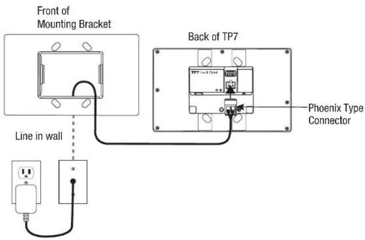
- By utilizing a 12v power supply (not included) to power the TP7 you may provide power locally or remotely. If powering locally be sure to run the wire through the wall in accordance with local codes. If powering remotely be sure to use wire of adequate gauge for the length of the run.
- Verify the polarity of your power supply prior to termination and ensure the power supply is not connected to a power source.
- Strip approx. 14 " of insulation from the wire and observing the correct polarity, terminate the wire into the supplied connector and tighten firmly. Be sure to twist the wires before inserting so that no strands escape the connector. Inspect the termination to verify that the wire is securely retained by the connector and no strands have escaped the barrier.
- Plug the connector into the TP7.
g. Connecting Ethernet
- When not utilizing PoE, but you have a physical network connection available it is recommended that you connect the TP7 directly to the network switch.
- Utilizing a T568A or T568B network cable connect to the LAN/PoE jack. If you have terminated your own CAT 5e/6/7 cable use a tester to ensure that both ends have been properly terminated.
h. Mounting the TP7
- The TP7 is held into the mounting bracket by spring steel tabs.
- Orient the TP7 with the POWER button at the top right for landscape mounting or the top left for portrait mounting.
- To complete the installation simply grasp the TP7 on the edges and press firmly on to the bracket until it is seatled.
CAUTION: DO NOT PRESS DIRECTLY ON THE SCREEN when installing on to the mounting bracket. Press only on the frame edges.

2
Powering up the TP7
The TP7 will automatically power on when power is applied. Wait for the unit to boot up.
- If connected to a wired Ethernet switch the TP7 will acquire a network address via DHCP and automatically connect to the system.
- If the TP7 does not detect a wired Ethernet connection and the WiFi radio has never been configured you will be presented with the Network Configuration Utility interface. To complete the network configuration please refer to the most current training documentation for your system.
3
Removing the TP7
- Using two hands grasp it on each side or the top and bottom and pull straight out from the wall. It will require approx. 10lbs of force to remove it from the bracket.

4 Setting screen orientation
The TP7 is shipped pre-configured for landscape orientation.
To change orientation:
- Press and hold power button for 3 seconds.
- Select Configure Panel from the popup menu.
- Select landscape or portrait orientation.

5
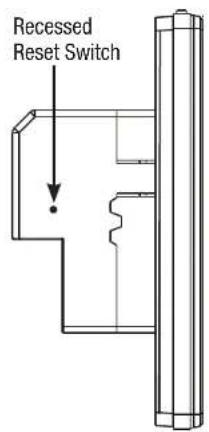
RESET
The recessed RESET button has two functions.
- Tap the button to reset the network configuration.
- Press and hold the button for 10 seconds to restore the TP7 to factory default configuration.
CAUTION:
Neither of these actions can be reversed.


Important Safety Instructions
- Read, understand and follow ALL safety and installation instructions included in this manual.
Failure to follow the included documentation may damage the product and will void manufacturer's warranty. - Follow ALL installation guidelines included with the product. Installation of the product in high humidity environments, in close proximity to heat sources and/or non-recommended locations WILL impede, interfere and/or damage the intended operation of the product
- Only use attachments and accessories which have been specified for use by the manufacturer.
- The use of abrasive, liquid or solvent based cleaning fluids WILL damage the product.
Please refer and follow all Product Care instructions included with the product. - Product Servicing may ONLY be completed by authorized or certified service centers & personnel.
For a complete list of product servicing options, please follow instructions included in the product documentation and /or contact original manufacturer for details.
FEDERAL COMMUNICATIONS COMMISSION INTERFERENCE STATEMENT:
This equipment has been tested and found to comply with the limits for a Class B digital device, pursuant to part 15 of the FCC Rules.
These limits are designed to provide reasonable protection against harmful interference in a residential installation. This equipment generates, uses and can radiate radio frequency energy and, if not installed and used in accordance with the instructions, may cause harmful interference to radio communications.
However, there is no guarantee that interference will not occur in a particular installation. If this equipment does cause harmful interference to radio or television reception, which can be determined by turning the equipment off and on, the user is encouraged to try to correct the interference by one or more of the following measures:
- Reorient or relocate the receiving antenna.
- Increase the separation between the equipment and receiver.
- Connect the equipment into an outlet on a circuit different from that to which the receiver is connected.
- Consult the dealer or an experienced radio/ TV technician for help.
FCC and IC Information:
This Class B digital apparatus complies with Part 15 of the FCC rules and with Canadian ICES-003 and RSS-210.
Operation is subject to the following two conditions:
- This device may not cause interference and
- This device must accept any interference, including interference that may cause undesired operation of the device.
Warning: Changes or modifications to this unit not expressly approved by the party responsible for compliance could void the user's authority to operate the equipment.
FCC and IC Radiation Exposure Statement:
This equipment complies with FCC radiation exposure limits set forth for an uncontrolled environment and meets the exemption from the routine evaluation limits in section 2.5 of RSS 102.
- This Transmitter must not be co-located or operating in conjunction with any other antenna or transmitter.
- This equipment complies with FCC RF radiation exposure limits set forth for an uncontrolled environment.
This equipment should be installed and operated with a minimum distance of 20 centimeters from user and bystanders.
Warning: The device meets the exemption from the routine evaluation limits in section 2.5 of RSS 102, and users can obtain Canadian information on RF exposure and compliance from the Canadian Representative Product Solutions Group at Tel: (519) 763-4538.
Thank you for including the TP7 as part of the user interface strategy for your customer. The TP7 has been designed to provide years of trouble free operation when wired and installed properly. The TP7 has been designed for installation in low humidity indoor environments and should never be installed outdoors or in high humidity areas.
Included in the box
- 1ea TP7 touch panel
- 1ea TP7 mounting bracket
- 4ea Mounting screws
- 1ea DC power connector
Introduction
To install the TP7 you will also need a standard 2 gang US junction box or low voltage bracket.
Specifications
Dimensions Overall 8"w x 5"h Mounting Depth 1 3/4"
Microphone Dual Digital Beam Forming
Far
Field
Pickup
Speaker 2w integrated
Camera 640 x 480
Display 7" 800 x 480
Network 10/100 Ethernet 802.11 B/G/N
WiFi
Connections
LAN/PoE RJ-45
Power 2 pin Phoenix
USB USB Type A
Audio Out 1/8" stereo (Future Use)
Power Requirements
Direct - 12V 1 A ===
PoE - IEEE 802.3at, 13w maximum
(@48V 270 mA max) ===
draw
Niles Auriel Control System for the Next-Gen Home Installation
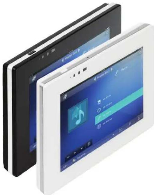
Introducing the Niles Auriel nTP7, a 7" touch panel controller with a contemporary industrial design for control of the Niles Auriel™ MRC-6430 multi-room audio control system. This touch panel is wall mountable in either portrait or landscape orientation to best suit the needs of your room and includes a speaker, microphone and color camera to accommodate future enhancements.
The high resolution interface makes this unit one of the most popular control devices on the market—second in popularity only to the traditional remote for its sleek appearance and simple user interface.
Not all touch panels are created equally – and the Auriel 7" touch panel leads the pack. The touchscreen is highly responsive, and the proximity sensor wakes it from sleep without any touch required. The front panel glass design makes this controller highly durable, easy to clean and resistant to scratches.
natural_image
Exterior view of a modern tablet device with open panels and a music player interface (no visible text or symbols on screen)nTP7
The touch panel is available in White and Black finishes and is single wire connected with power over Ethernet.
FEATURES:
- 7" diagonal viewable area LCD touchscreen interface
• Contemporary, sleek Industrial Design - Edge to edge glass
- Capacitive sense touchscreen
-
Proximity sensor to wake from sleep without touching as hand approaches
-
Mounts into drywall, brick, stone, plaster, wood using a standard 2g U.S. junction box
• Portrait or landscape mounting
• Supports TCP/IP communication - Wi-Fi support
- Plug and play operation with Niles Auriel Software
- Locally powered (optional)
• Available in White and Black bezel
SPECIFICATIONS:
| Dimensions Overall 8" wide x 5" height, mounting depth 1.75" | |
| Screen size 7-inch diagonal, 16:9 widescreen | |
| Resolution 800W x 480H | |
| Microphone Dual Digital Beam Forming for Field Pickup | |
| Speaker 2W integrated | |
| Camera 640X x 480H | |
| Network 10/100 Ethernet / 802.11 B/G/N WiFi | |
CONNECTIONS:
| Type LAN/PoE: RJ-45 | |
| Power Requirements | PoE (Power over Ethernet) EEE 802.3at, 13w maximum draw (@48 V== 270 mA max) |
| USB USB Type A | |
| Audio Out 1/8" stereo mini (Future Use) | |
POWER REQUIREMENTS:
| Direct 12 V , 1 A. Phoenix | 2 pin screw terminal connector |
| PoE | IEEE 802.3at, (power over Ethernet) 13w maximum draw (@48V== 270 mA max) |
Get your App:
www.NilesAudio.com/Auriel


NILES®

- TP7 – 7" Touch Panel
- User Interface
- Quick Install Guide
- Planning the installation
- Installing the TP7
- a. Mounting height
- b. Rough-In
- c. Landscape Mounting
- d. Portrait Mounting
- e. Installing the TP7 Bracket
- f. Connecting the TP7 to power
- PoE Connection
- 12v Power Supply
- g. Connecting Ethernet
- h. Mounting the TP7
- 2
- Powering up the TP7
- 3
- Removing the TP7
- Setting screen orientation
- To change orientation:
- 5
- RESET
- CAUTION:
- Important Safety Instructions
- FEDERAL COMMUNICATIONS COMMISSION INTERFERENCE STATEMENT:
- FCC and IC Information:
- Operation is subject to the following two conditions:
- FCC and IC Radiation Exposure Statement:
- Included in the box
- Introduction
- Specifications
- Connections
- Power Requirements
- Niles Auriel Control System for the Next-Gen Home Installation
- FEATURES:
Brand : Niles
Model : TP7
Category : Controller