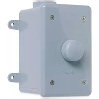
WVC100E - Controller Niles - Free user manual and instructions
Find the device manual for free WVC100E Niles in PDF.


| Product Type | Audio/Video Controller |
| Brand | Niles |
| Model | WVC100E |
| Dimensions (W x H x D) | 17 x 2 x 8 inches (approx.) |
| Weight | 5 lbs (approx.) |
| Power Supply | 120V AC, 60Hz |
| Power Consumption | 15W (max) |
| Inputs | 4 x RCA stereo, 1 x 3.5mm |
| Outputs | 2 x RCA stereo, 1 x speaker level |
| Frequency Response | 20Hz - 20kHz ±0.5dB |
| Signal-to-Noise Ratio | >90dB |
| Total Harmonic Distortion | <0.05% |
| Channels | 2 (stereo) |
| Functions | Volume control, source selection, bass/treble adjustment |
| Remote Control | IR remote included (batteries not included) |
| Rack Mountable | Yes, 1U |
| Construction | Metal chassis, black finish |
| Cleaning | Wipe with a dry, soft cloth. Do not use liquids. |
| Safety | Do not expose to moisture or extreme temperatures. |
| Spare Parts | Contact Niles customer service for replacement parts. |
Frequently Asked Questions - WVC100E Niles
User questions about WVC100E Niles
0 question about this device. Answer the ones you know or ask your own.
Ask a new question about this device
Download the instructions for your Controller in PDF format for free! Find your manual WVC100E - Niles and take your electronic device back in hand. On this page are published all the documents necessary for the use of your device. WVC100E by Niles.
USER MANUAL WVC100E Niles
Miami, Florida 33186
Tel: (305) 238-4373
Fax: (305) 238-0185
07.2021 Niles Auto Construction: All rights reserved. Nets the Bahamas logo, and Branch High Priority and the Niles Auto Management Technology of Niles Audio Corporation. Decor a registered trademark or license Manufacturing. All other trademarks are the products of their respective companies. Some of Niles products include parents thereof, administrators and land under license authority. U.S. Patents, foreign equivalents and/or pending patentee for product detail. Because we currently strive to improve our products, Niles receives the right to charge product specifications, descriptions, and prices without notice. The technical and other features of information contained herein is not intended to sell from all technical and other specializations of Niles products. Additional information can be obtained at www.ileasudc.com or by calling Niles at 1,008,259-4134. Printed in China 2015 Pub:1111.CN
Features and Benefits 2
Installation Considerations 3
Installation 5
Operation 6
Specifications 8
Contents 9

NILES®
WEATH
RPROO! STEREO VOLUME CONTROLS
INTRODUCTION
The WVC 100 and WVC 100E are weatherproof stereo impedance-magnifying volume controls that connect between the speaker-level output of an amplifier, speaker selector, or a Niles VCS HUBB distribution hub and your speakers.
The WVC 100 is a wall-mounted volume control designed specifically for environmental use. The WVC 100E is a freestanding volume control mounted in a PVC junction box for use in environmental where a wall-mounted volume control would be impractical.
Both models adjust the volume of remotely located speakers to which they are connected by attenuating the amplifier signal. To assure minimal dissipation of internal power with virtually no power wasted as heat, Niles volume controls use autoformers instead of L-pads as the volume-controlling element.
The WVC 100 and WVC 100F are impedance-magnifying (IM) volume controls. Unlike other brands, they have additional autofomer windings that magnify the impedance of connected speakers, while allowing all 12 steps to adjust the volume of the sound. Switches on the PC board select these windings.
With the volume control providing impedance protection for your amplifier, you can create systems with no additional impedance-matching devices between the volume control and the amplifier.
In a typical application of 1M controls, a system has eight pairs of 8-ohm speakers throughout the house and in outdoor locations. Connect each pair of speakers to a WVC 100yF volume control with its switch in the 8x position, eliminating the need for an external impedance-matching device to protect the amplifier. Even when playing all eight speaker pairs at once, the amplifier runs at normal operating temperatures.
WATHERPROOF STERIO VOLUME CONTROLS
FEATURES AND BENEFITS
The weatherproof WVC 100 and WVC 100E offer a number of improvements over other weatherproof volume controls:
- WVC 100: Designed for environmental wall-mount installation.
- WVC 100E: Enclosed in a freestanding PVC junction box, designed for installations where wall mounting would be impractical.
- Both models: A rubber gasket fits behind the faceplate during installation to scal out moisture.
- An impedance-magnifying switch on the front of the volume control sets the impedance of connected speakers. You can magnify the speakers' impedance by a factor of two, four, or eight.
- Unlike other impedance-matching volume-control products, Niles IM volume controls maintain a 12-position adjustment regardless of how much impedance magnification you use, with total attenuation >48dB.
• Pop-free switching between all steps. -
100-percent tested, electronically and acoustically, for frequency response, distortion, and power handling.
-
WVC 100: Mounting depth of only 2-9/16". Fits into standard 18-cubic-inch one-gang junction boxes.
• WVC 100E: Fits into PVC junction box (supplied). - Standard faceplate and knob included.
- Isolated left- and right-channel grounds ensure safety with any amplifier.
- May be used with 4-, 6-, or 8-ohm speaker systems.
- Ideal for home and commercial sound installations.
- UL-rated to comply with all local building codes.
- Installation requires only a screwdriver and wire stripper.
• Power handling: 100W/channel RMS.
• Frequency response: 20Hz to 20kHz ±1.5dB.
■ WVC 100: Available colors: Bone and White. - Ten Years parts and labor warranty.
TECH TIP
Some speakers have selectable impedance. Before you proceed, please confirm that any selectable-impedance speakers in your system are properly set for the system you are installing.
WAIHIERPROJ STIKIO VOLUMI CONTROLS
WATHERROOT SIKIO VOLUMI CONTROLS
INSTALLATION CONSIDERATIONS
Calculating the Impedance Magnification Setting
Use the following instructions and the accompanying charts to select the correct switch setting for the number and type of speakers in your system.
CAUTION! Every speaker pair in the system must be connected to an impedance-magnifying volume control and set to the same magnification.
- Count the number of pairs of 4-ohm speakers and the number of pairs of 8-ohm speakers you are connecting. Count pairs of 6-ohm speakers as 4-ohm pairs.
- Determine whether the amplifier should see a 4-ohm load or
an 0-ohm load. You should find this information in the owner's manual of the amplifier. - Read the correct switch position from the charts on page 7. See Figure 3 if your amplifier can drive a 4-ohm load. See Figure 4 if your amplifier must have an 8-ohm speaker load.
- 1/4" Standard
Slotted Screwdriver - Wire Stripper
TOOLS REQUIRED
• 1/8" Standard Slotted Screwdriver
- Set the switches on all of the controls to the same position (1x, 2x, 4x, or 8x).
Limitations in Volume with High Magnification Settings
Using an 8x setting limits the power to each speaker pair to one-eighth of the amplifier's output.
In a typical application of IM volume controls, a system has eight pairs of 8-ohm speakers throughout the house. Each pair of speakers is connected to an IM volume control with its switches set for 8x.
With eight pairs of speakers, one-eighth of the amplifier's power is available to any pair. Therefore, an amplifier rated at 100W per channel RMS into 8 ohms will deliver up to 12.5W to each of the eight pairs – whether you play all eight pairs or just one pair. This translates into a drop in

the maximum volume capability of about 9dB at the 8x setting.
USING SPEAKER SELECTORS WITH IM VOLUME CONTROLS
Although IM controls provide volume and on/off at the volume-control location, they do not give you central control of speakers playing throughout the house. Speaker-selection systems give you central control, but some speaker selectors have non-detectable impedance-protection circuits. Combining IM controls with such a selector will reduce your maximum volume substantially. To solve this problem, specify a speaker selector with a detectable protection circuit (Niles models HDL-4, HDL-6, SPS-4, or SPS-6). Then keep the protection circuit off at all times.
JUNCTION BOXES
WVC 100: The mounting depth of the WVC 100 is 2.9/16". When installed, the unit extends 2-1/16" behind the sheetrock wall (assuming 1/2" sheetrock). For installation, use a standard 18-cubic-inch (or larger) junction box. Suitable junction boxes are available from your Niles dealer or local electrical-supply company.
WVC 100E: Use the PVC junction box (supplied), mounted atop a PVC conduit through which the wires will run.
TYPE OF SPEAKER WIRE
We recommend 16-gauge stranded copper speaker wire for most connections, and 14-gauge wire for runs longer than 80 feet. Don't use speaker wire larger than 14 gauge, because larger wire may not fit into the connectors. Never use solid core, aluminum, or Romex wire with an IIA volume control. For speaker wire runs within walls, most U.S. states and municipalities require a special type of speaker wire with a specific CLI tire rating, such as CL-2 or CL-3. Consult your Niles dealer, building contractor, or local building-inspection department if you aren't sure what kind of wire is best for your application.
MOUNTING LOCATION
WVC 100: Convenient mounting locations include:
- On a porch or patio wall.
- Near doorways.
- Close to a telephone.
- Near other wall-mounted controls.
WVC 100E: Convenient mounting locations include:
- At poolside.
- Near a hot tub.
- Near a barbecue.
- In other locations where a wall-mounted volume control would be impractical.
Some states or municipalities allow installation of devices such as the WVC 100 in the same junction box as 110V devices, with a low-voltage partition between the devices. We do not recommend this, because speaker wires can act as an antenna for electrical noise. Locating speaker wires too close to a light switch or dimmer may cause the speakers to emit a popping or buzzing sound. If you must locate the IM volume control near electrical devices, install it in a separate metal junction box, ground the box to the electrical-system ground, and route the speaker wires several feet away from the electrical wiring.
PREPARING FOR INSTALLATION
WVC 100: Before you install the WVC 100 into an existing wall, consider the possibility of hidden obstructions inside the wall, such as wood and metal studs; electrical, telephone, or other wiring; plumbing; and conduit.
- Install the junction box in the usual manner.
- Run all necessary wiring to the volume control. Label the wires for future reference (Figures 1).
WVC 100E:
- Run the necessary wiring up through the conduit and the opening at the base of the enclosure. Label the wires for future reference (Figures 1).
- Mount the entire enclosure atop the PVC conduit.
INSTALLATION
- Locate the connector plugs (and remove them if they are plugged in).
- Strip 1/4" of insulation from the end of each wire. Tightly twist the end of each wire until no frayed ends remain.
- Use a small flathead screw-driver or your thumbnail to raise the locking tabs, exposing the holes on the removable connector plug.
- Insert each wire into the appropriate hole on the removable connector plug, and snap the locking tab down.
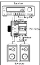
Figure 1
Wiring Diagram
NOTE: Maintain proper phasing. Connect the positive terminals on the volume control to the positive terminals on the amplifier and speakers, and connect the negative terminals on the volume control to the negative terminals on the amplifier and speakers. To help you avoid improper phasing, the con-
nector plug is keyed. Insert the smooth side of the connector plug into the smooth side of the socket. Don't force the scalloped side of the connector plug into the smooth side of the socket. See Figure 5.
- Set the Impedance Magnification Switch (See Figure 6) as determined by the IM charts (Figures 3 and 4).
- Plug the connectors into the volume control as shown in Figure 5. The inputs of the IM volume control are the connector pins labeled AMPLIFIER. The outputs are the connector pins labeled SPEAKERS.
NOTE: If you reverse these connections, the volume control won't function properly.
-
Secure the volume control to the junction box. Insert the 1-1/4 device screws into the oblong screw holes on the top and bottom of the volume control. The oblong shape of the screw holes helps you place the volume control in a vertical position. Align the screws with the threaded holes in the junction box. Tighten the screws using a Phillips screwdriver. DO NOT OVERTIGITEN. If necessary, loosen these screws several turns so the volume control fits flush with the faceplate.
B. Set the rubber gasket inside the faceplate and be sure it is seated properly. -
Use the shorter plate screws to fasten the gasketed faceplate to the volume control. DON'T OVERTIGHTEN THE PLATE SCRFWS, WHICH COULD DAMAGE THE FACEPLATE. Align all the screws in the same direction for a clean, finished look.
OPERATION
- Make sure the amplifier or receiver power is OFF and set the volume to minimum.
- Set the volume on the volume control to maximum (fully clockwise).
- If you are using a Niles speaker selection system, locate the ON/OFF button that corresponds to the speaker pair you wish to play. Set it to the ON position. Make sure the defeatable protection circuit is not enabled. See Using Speaker Selectors with IM Volume Controls, on page 4.
- Turn ON the amplifier or receiver and select a source, such as the tuner or CD player.
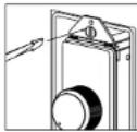
Figure 2
Locscening the Screws for a Flush Fit
WIAIHI KPROO! STIRIO VOLUMI CONTROLS
AMPLIFIER'S MINIMUM SPEAKER LOAD IS 4 OHMS
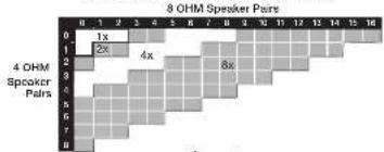
Figure 3

Figure 5
AMPLIFIER'S MINIMUM SPEAKER LOAD & B CHMS

Figure 4
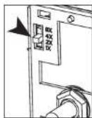
Figure 6
WHATISHPROOF SIERIO VOLUMI CONTROLS
- Slowly turn up the amplifier or receiver volume and set it to a comfortable – not maximum – listening level. Don't overdrive or "clip" your amplifier. If the sound becomes muddy or distorted, you have reached the limit of your amplifier's volume capability. Reduce the volume at once to avoid damaging your speakers.
- Use the volume control to adjust the volume of the speakers to the desired listening level. If all the speaker pairs in your system are equipped with Niles volume controls, you can set the amplifier or receiver volume at one position and use the Niles controls exclusively.
- To turn off the speakers, turn the knob on the volume control fully counter-clockwise, or press the ON/OFF button on your speaker selector.
SPECIFICATIONS
Audio Power Handling
TOOW-channel RMS
200W/channel peak music power
Mounting
WMVC-100: In-wall, fits into most 18-cubic inch single gang junction boxes at least 2-3/4" deep
WMVC-100E: Enclosed in a PVC junction box (supplied)
Wiring Requirements
14-18 gauge, two individual runs of two-conductor speaker wire, or one run of four-conductor speaker wire.
Unit Dimensions
1-5/8" wide x 2-5/8" high
Faceplate Dimensions
Faceplate: 2-3/4" wide x 4-1/2" high
Depth Behind Faceplate
2-9/16
TECH TIP
When using a receiver, set all of your IM volume controls at maximum volume. Then turn up the master volume on the receiver until you reach the maximum listening level. Finally, turn down the volume controls.
WAIHIERPROOF STIKIO VOLUMI CONTROLS
CONTENTS
WVC100
• WVC100 volume control
• Standard wallplate
• Knob
• Device mounting screws X2
• Faceplate screws X2
- Removable speaker connector X2
• Casket
WVC100E
• WVC100F Volume Control
• Knob
• Device mounting screws X2
• Removable speaker connector X2
• Standard Facenplate screws X4
• Enclosure XI
• Casket
WAIHIERPROO! SITKIO VOLUMI CONTROLS

Figure 7


- INTRODUCTION
- FEATURES AND BENEFITS
- TECH TIP
- INSTALLATION CONSIDERATIONS
- Calculating the Impedance Magnification Setting
- TOOLS REQUIRED
- Limitations in Volume with High Magnification Settings
- USING SPEAKER SELECTORS WITH IM VOLUME CONTROLS
- JUNCTION BOXES
- TYPE OF SPEAKER WIRE
- MOUNTING LOCATION
- PREPARING FOR INSTALLATION
- WVC 100E:
- INSTALLATION
- OPERATION
- SPECIFICATIONS
- CONTENTS
- WVC100
- WVC100E
Brand : Niles
Model : WVC100E
Category : Controller