
CP-X990W - Video projector HITACHI - Free user manual and instructions
Find the device manual for free CP-X990W HITACHI in PDF.

| Product Type | Liquid Crystal Projector |
| Display Technology | TFT Active Matrix, 1.3-inch panel, 786,432 pixels (1024x768) |
| Lens | Zoom lens F=1.7~2.3, f=49.0~64.0 mm |
| Lamp | 275 W UHB (Ultra High Brightness) |
| Speaker | 1.2 W + 1.2 W stereo |
| Power Supply | AC 100-120V 4.7A / AC 220-240V 2.0A |
| Power Consumption | 440 W |
| Operating Temperature | 0°C to 35°C (32°F to 95°F) |
| Dimensions (W x H x D) | 289 x 144 x 350 mm (11.4 x 5.7 x 13.8 in) |
| Weight | 6.5 kg (14.3 lbs) |
| Input Terminals | RGB IN 1/2 (D-sub 15-pin), DVI, Video (RCA), S-Video (mini DIN 4-pin), Component Video (3 RCA), Audio (stereo mini jack x2, RCA L/R) |
| Output Terminals | RGB OUT (D-sub 15-pin), Audio OUT (stereo mini jack) |
| Control Terminals | USB (B type), CONTROL (D-sub 15-pin for RS-232C/mouse) |
| Key Features | Partial magnification, distortion correction (keystone), freeze function, PIP (Picture-in-Picture), auto adjustment, whisper mode |
| Image Adjustments | Brightness, contrast, sharpness, color, tint, color balance, gamma, aspect ratio (4:3, 16:9, small) |
| Lamp Life | Approximately 2000 hours (typical); indicator warns when replacement needed |
| Filter Maintenance | Clean air filters every 100 hours; replace if damaged |
| Optional Parts | Lamp (DT00491), Air filter (MN04531) |
| Security | Safety lock hole; complies with FCC Class B, ICES-003 |
Frequently Asked Questions - CP-X990W HITACHI
User questions about CP-X990W HITACHI
0 question about this device. Answer the ones you know or ask your own.
Ask a new question about this device
Download the instructions for your Video projector in PDF format for free! Find your manual CP-X990W - HITACHI and take your electronic device back in hand. On this page are published all the documents necessary for the use of your device. CP-X990W by HITACHI.
USER MANUAL CP-X990W HITACHI
Please read this user's manual thoroughly to ensure correct usage through understanding.
BEDIENUNGSANLEITUNG
natural_image
Line drawing of a projector with control panel and display (no text or symbols)HITACHI
Hitachi America, Ltd.
Computer Division 2000 Sierra Point Parkway, MS760 Brisbane, CA 94005-1835
Tel: +1-800-225-1741 Fax: +1-650-244-7776
www.hitachi.com/lcd.
Hitachi Canada, Ltd.
6740 Campobello Road, Mississauga, Ontario L5N2L8, Canada
Tel: +1-905-821-4545 Fax: +1-905-821-1101
Hitachi Home Electronics (Europe), Ltd.
Dukes Meadow, Millboard Road, Bourne End, Buckinghamshire SL8 5XF UK
Tel: +44-162-864-3000 Fax: +44-162-864-3400
Hitachi Home Electronics Europe Ltd
426 Bergensesteenweg, 1500 Halle, Belgium
Tel: +32-2-363-9901 Fax: +34-2-363-9900
Hitachi Home Electronics Europe Ltd
Gewerbepark, Hintermattlistr, Postfach, 5506 Magenwil, Switzerland
Tel: +41-62-889-8011 Fax: +41-62-896-4771
Hitachi Europe GmbH
Business Systems Division
Via T. Gulli. 39, 20147 Milano, Italy
Tel: +39-2-487861 Fax: +39-2-48786322
Hitachi Sales Europe GmbH
Business Systems Division
Am Seestern 18, 40547 Dusseldorf, Germany
Tel: +49-211-529-1551 Fax: +49-211-529-1594
Hitachi Business Systems (Nordic)
Brugata 14, N-0184 Oslo, Norway
Tel: +47-2205-9060 Fax: +47-2205-9061
Hitachi Business Systems (Nordic)
Domnarvsgatan 29, Lunda, Box 62, S-163 91
Spanga, Sweden
Tel: +46-8-621-8260 Fax: +46-8-761-6250
Hitachi Business Systems (Nordic)
Kuldyssen 13, DK-2630 Tästrup, Denmark
Tel: +45-43-99-9200 Fax: +45-43-99-9392
Hitachi Business Systems (Nordic)
Tapiolan Keskustorni 11 Krs. Fin-02100 Espoo, Finland
Tel: +358-9-3487-1188 Fax: +358-9-455-2152
Hitachi France
Immeuble, 'Ariane', 18 Rue Grange Dame Rose, B.P. 134, 78148 Velizy, Cedex, France
Tel: +33-1-34630542 Fax: +33-1-34650761
Hitachi Sales Iberica S A
Gran Via Carlos 111, 101, 1-1, 08028 Barcelona, Spain
Tel: +34-3-330-8652 Fax: +34-3-339-7839
Hitachi Home Electronics Asia, (S) Pte Ltd.
16 Collyer Quay #20-00 Hitachi Tower Singapore 049318, Singapore
Tel: +65-536-2520 Fax: +65-536-2521
Hitachi Sales (Malaysia) Sdn. Bhd.
Wisma Hitachi, No.2, Lorong 13/6A, 46200 Petaling
Jaya, Selangor Darul Ehsan, Malaysia
Tel: +60-3-7573455 Fax: +60-3-7556090
Hitachi Sales (Thailand), Ltd.
994,996 Soi Thonglor, Sukhumvit 55 Road, Klongton,
Klongtoey, Bangkok 10110, Thailand
Tel: +66-2-381-8381 Fax: +66-2-381-9520
Hitachi (Hong Kong), Ltd.
8th Floor Park-in Commercial Centre, No.56, Dundas
Street, Kowloon Bay, Kowloon, Hong Kong
Tel: +852-2-7804351 Fax: +852-2-7804915
Hitachi Sales Corp. of Taiwan.
2nd Floor, No.65, Nanking East Road, Section 3, Taipei, Taiwan
Tel: +886-2-516-0500 Fax: +886-2-516-1501
Hitachi Australia Ltd.
13-15 Lyonpark Road, North Ryde NSW 2113, Australia
Tel: +61-2-9888-4100 Fax: +61-2-9888-4144
Hitachi, Ltd.
15-12, Nishi Simbashi 2-chome, Minato-ku, Tokyo, 105 Japan
Tel: +81-3-3502-2111 Fax: +81-3-3506-1440

*QR51581*
Liquid Crystal Projector
USER'S MANUAL
Thank you for purchasing this liquid crystal projector.
WARNING • Please read the accompanying manual “SAFETY INSTRUCTIONS” and this “USER'S MANUAL” thoroughly to ensure correct usage through understanding. After reading, store this instruction manual in a safe place for future reference.
NOTE • The information in this manual is subject to change without notice.
- The manufacturer assumes no responsibility for any errors that may appear in this manual
- The reproduction, transmission or use of this document or contents is not permitted without express written authority.
TRADEMARK ACKNOWLEDGMENT : PS/2, VGA and XGA are registered trademarks of International Business Machines Corporation. Apple, Mac and ADB are registered trademarks of Apple Computer, Inc. VESA and SVGA are trademarks of the Video Electronics Standard Association. Windows is a registered trademark of Microsoft Corporation. Carefully observe the trademarks and registered trademarks of all companies, even when not mentioned.
CONTENTS
Page
FEATURES 2
BEFORE USE 2
Contents of Package 2
Part Names....3
Loading the Batteries....5
INSTALLATION 6
Installation of the Projector and Screen .....6
Angle Adjustment ....6
Cabling 7
Power Connection 8
Example of System Setup 8
Plug & Play....8
OPERATIONS....9
Power ON 9
Power OFF 9
Basic Operation....10
Setup Menu 12
Input Menu....13
Image Menu....14
Options Menu ....15
No Signal Menu....16
MAINTENANCE ....17
Lamp....17
Air Filters 19
Other Maintenance....19
Page
TROUBLESHOOTING ....20
OSD Message ......20
Indicators Message 21
Symptom 22
SPECIFICATIONS......23
WARRANTY AND AFTER-SERVICE.....24
TABLES
Table 1. Installation Reference......6
Table 2. Cabling ......7
Table 3. Basic Operations .....10
Table 4. Setup Menu .....12
Table 5. Input Menu....13
Table 6. Image Menu....14
Table 7. Options Menu ....15
Table 8. No Signal Menu....16
Table 9. OSD Message .....20
Table 10. Indicator Message .....21
Table 11. Symptom .....22
Table 12. Specifications .....23
For "TECHNICAL" and "REGULATORY NOTICE", see the end of this manual.
This liquid crystal projector is used to project various computer signals as well as NTSC / PAL / SECAM video signals onto a screen. Little space is required for installation and large images can easily be realized.
Outstanding Brightness
The UHB lamp and high-efficiency optical system assure a high level of brightness.
Partial Magnification Function
Interesting parts of images can be magnified for closer viewing.
Distortion Correction Function
Distortion-free images are quickly available.
BEFORE USE
Contents of package
Make sure all of the following items are included in the package. If anything is missing, please contact your dealer.
NOTE • Keep the original packing material for future reshipment.
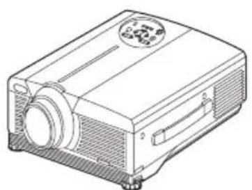
natural_image
Line drawing of a projector with a circular button and ventilation grille (no text or symbols)Projector
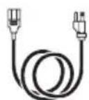
Power Cord (US Type)
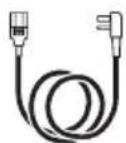
Power Cord (UK Type)
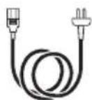
Power Cord (Europe Type)
User's Manual (this manual)
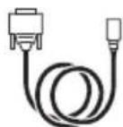
RGB Cable
Component Video Cable
Safety Instructions
Mouse cable (PS/2)
Batteries
for Remote Control
Transmitter
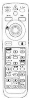
Remote Control
Transmitter
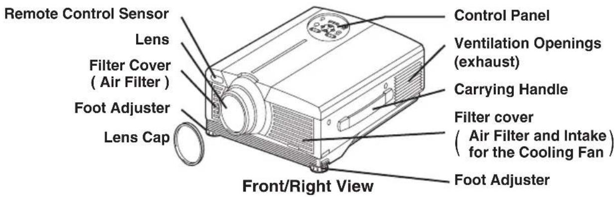
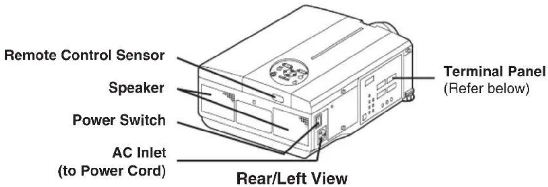
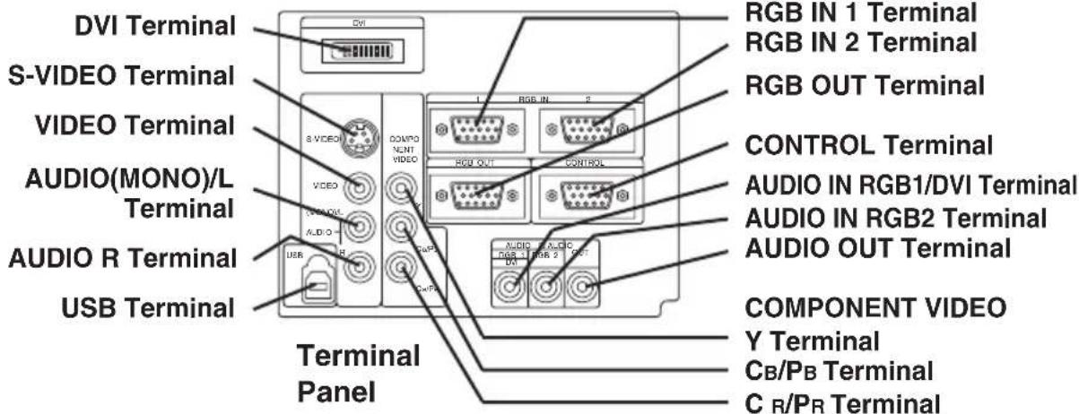
Part Names
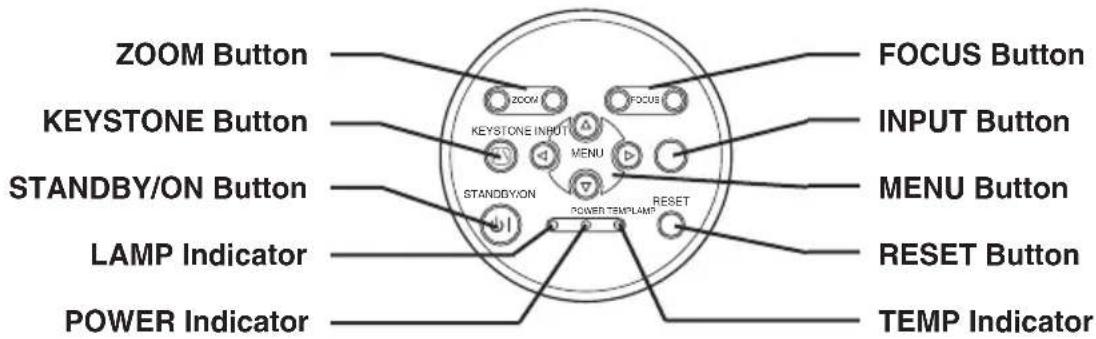
Control Panel
(Refer to P.9 "OPERATIONS")
Part Names (continued)
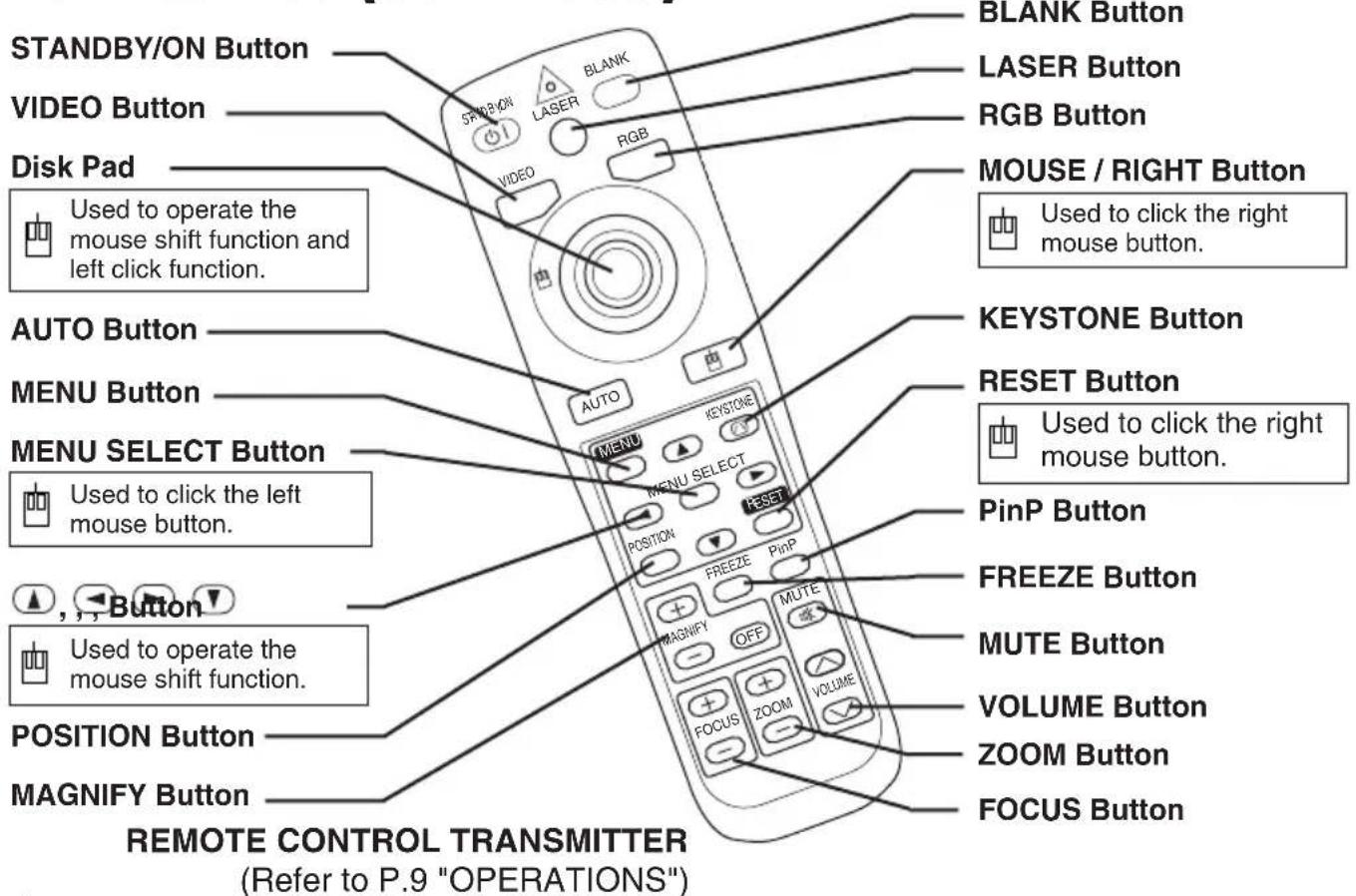
These functions works when the mouse control function is activated. Remember, the POSITION, BLANK ON and MENU ON functions disable the mouse control function.
WARNING • The laser pointer of the remote control transmitter is used in place of a finger or rod. Never look directly into the laser beam outlet or point the laser beam at other people. The laser beam can cause vision problems.
CAUTION • Use of controls or adjustments or performance of procedures other than those specified herein may result in hazardous radiation exposure.
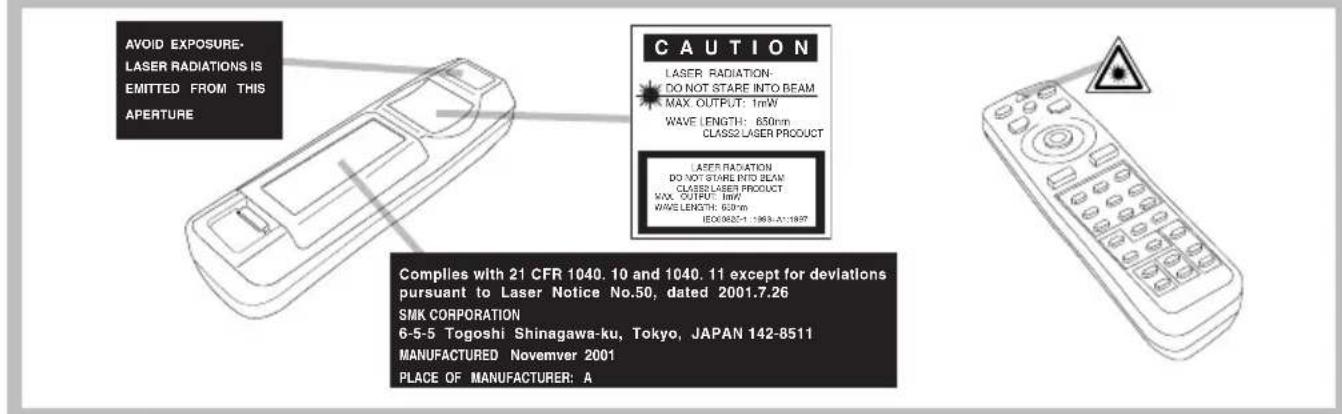
NOTE • Keep the remote control transmitter away from children and pets.
- Do not give the remote control transmitter any physical impact. Take care not to drop.
- Do not place the heavy objects on the remote control transmitter.
- Do not wet the remote control transmitter or place it on any wet object.
- Do not place the remote control transmitter close to the cooling fan of the projector.
- Do not disassemble the remote control transmitter.
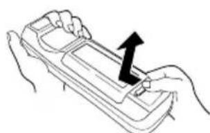
Loading the Batteries
Install the AA batteries into the remote control transmitter.
-
Remove the battery cover. Push the knob while lifting up the battery cover.
-
Load the batteries. Make sure the plus and minus poles are correctly oriented.
-
Close the battery cover.
natural_image
Line drawing of hands holding a tray with an arrow indicating upward movement (no text or symbols)1

CAUTION • Use only the specified batteries with this remote control transmitter. Also, do not mix new and old batteries. This could cause in ery cracking or leakage, which could result in fire or personal injury.
- When loading the batteries, make sure the plus and minus terminals are correctly oriented as indicated in the remote control transmitter. Incorrect orientation could cause battery cracking or leakage, which could result in personal injury or pollution of the surrounding environment.
- When you dispose the battery, you should obey the law in the relative area or country.
- Keep the battery away from children and pets.
- When not to be used for an extended period, remove the batteries from the remote control transmitter.
NOTE Replace the batteries when remote control transmitter operation becomes difficult.
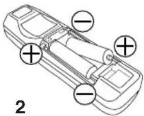
Installation of the Projector and Screen
Refer to the drawing and table below for determining of the screen size and projection distance.
The projection distances shown in the table below are for full size (1024 x 768 dots).
a: Distance from the projector to the screen. (±10%)
b: Distance from the lens center to the bottom of the screen. (±10%)
Table 1. Installation Reference
| Screen size[inches (m)] | a[inches (m)] | b[inches (cm)] | |
| Min. Max. | |||
| 40 (1.0) 55 | (1.4) 73 (1 | .9) 1 (3) | |
| 60 (1.5) 85 | (2.2) 114 | (2.9) 2 (4) | |
| 80 (2.0) 11 | (2.9) 151 | (3.8) 2 (6) | |
| 100 (2.5) 14 | (3.7) 191 | (4.9) 3 (7) | |
| 120 (3.0) 17 | (4.5) 231 | (5.9) 3 (9) | |
| 150 (3.8) 22 | (5.6) 282 | (7.2) 4 (11) | |
| 200 (5.0) 29 | (7.4) 386 | (9.8) 6 (15) | |
Screen
natural_image
Diagram of a projector with a top view indicator (no text or symbols on the diagram itself)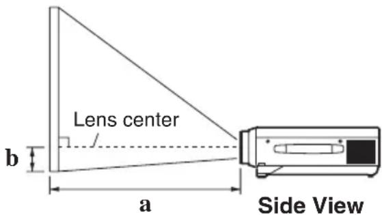

CAUTION • Install the projector in a suitable environment according to instructions of the accompanying manual “SAFETY INSTRUCTIONS” and this manual.
- When you fix this unit with a metal tool and the like, you must connect it with ground wire; otherwise, fire or electric shock can result.
Connect the ground terminal of AC inlet of this unit with the ground terminal provided at the building using an optional three-core power-supply cord.
- Please basically use liquid crystal projector at the horizontal position. If you use liquid crystal projector by the lens up position, the lens down position and the side up position, this may cause the heat inside to build up and become the cause of damage. Be especially careful not to install it with ventilation holes blocked.
- Do not install LCD projector in smoke effected environment. Smoke residue may buildup on critical parts (i.e.LCD panel, Lens Assy etc.).
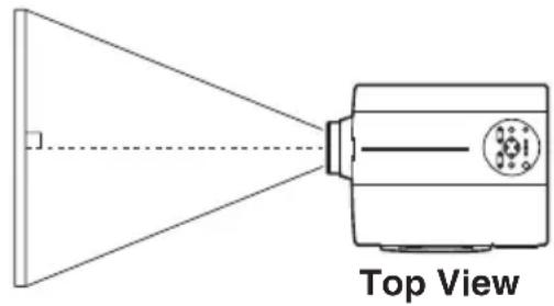
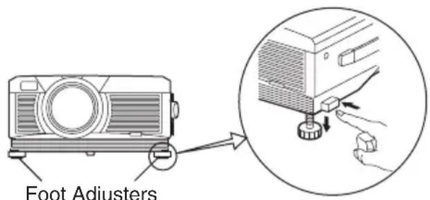
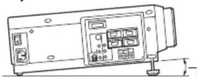
Angle Adjustment
Use the foot adjusters on the bottom of the projector to adjust the projection angle. It is variable within 0^ to 9^ approximately.
- Lift up the front side of the projector, and pressing the foot adjuster button, adjust the projection angle.
- Release the button to lock at the desired angle.
- Make the foot adjusters screw for fine adjustment. Do not force the adjusters to make screw. This could damage the adjusters or cause the lock to fail.
natural_image
Line drawing of a device casing with control panel and mounting base (no text or symbols)Variable within the range of approximately 0^ - 9^

CAUTION • Do not release the foot adjuster button unless the projector is being held; otherwise, the projector could overturn or the fingers could get right and cause personal injury.
Cabling
Refer to the table below for connecting each terminal of the projector to each device.
Table 2. Cabling
| Function Terminal | Cable | |
| Analog RGB input | RGB IN 1 | Accessory or optional RGB cable with D-sub 15-pin shrink jack and inch thread screws |
| RGB IN 2 | ||
| Analog RGB output RGB OUT | ||
| Digital RGB input DVI Optional | DVI cable with inch thread screws | |
| Audio input(from the computer) | AUDIO IN [RGB 1] / [DVI](interlocked with RGB IN 1 or DVI) | Optional audio cable with stereo mini jack |
| AUDIO IN [RGB 2](interlocked with RGB IN 2) | ||
| PS/2 mouse control | DB mouse cableCONTROLserial mouse cable | Accessory PS/2 mouse cable |
| ADB mouse control Optional AD | ||
| Serial mouse control Optional S | ||
| RS-232C communication Optional | RS-232C cable | |
| USB mouse control USB | Optional USB cable | |
| S-video input | S-VIDEO | Optional S-video cable with mini DIN 4-pin jack |
| Video input | VIDEO | Optional video/audio cable |
| Component video input | COMPONENT VIDEO Y | Accessory component video cable |
| COMPONENT VIDEO CB/PB | ||
| COMPONENT VIDEO CR/PR | ||
| Audio input(from video equipment) | AUDIO (MONO)/L | Optional video/audio cable or optional audio cable with RCA jack |
| AUDIO R | ||
| Audio output | AUDIO OUT | Optional audio cable with stereo mini jack |

CAUTION • Incorrect connecting could result in fire or electrical shock. Please read this manual and the separate “SAFETY INSTRUCTIONS”.
- Before connecting, turn off to all devices to be connected, except for the USB cable.
- The cables may have to be used with the core set to the projector side. Use the cables which are included with the projector or specified.
NOTE • Before connecting, read instruction manuals of the devices to be connected, and make sure that the projector is compatible with the device.
- Secure the screws on the connectors and tighten.
- For some RGB input modes, the optional Mac adapter is necessary.
- To select the DVI input, the computer may need some settings. See the manuals of the computer for details.
- Some computers may have multiple display screen modes. Use of some of these modes will not be possible with this projector.
- Refer to the “TECHNICAL” section for the pin assign of connectors and RS-232C communication data.
- When the DVI terminal is used, the RGB OUT terminal may not function.
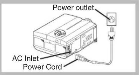
Power Connection
Use the correct one of the enclosed power cords depending on the power outlet to be used. Connect the AC inlet of the projector to the power outlet firmly by the power cord.

CAUTION • Be carful in handling the power cord according to instructions of the companying manual "SAFETY INSTRUCTIONS" this manual.
- Connect the power cord firmly. Avoid using a loose, unsound outlet or contact failure.
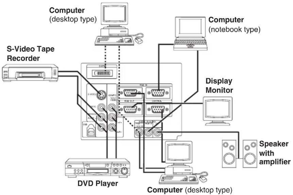
Example of system setup
flowchart
graph TD
    A["Computer (desktop type)"] --> B["S-Video Tape Recorder"]
    B --> C["Display Monitor"]
    C --> D["Computer (notebook type)"]
    D --> E["Speaker with amplifier"]
    E --> F["Computer (desktop type)"]
    F --> G["Display Monitor"]
    G --> H["Computer (notebook type)"]
    H --> I["Display Monitor"]
    I --> J["Computer (notebook type)"]
    J --> K["Display Monitor"]
    K --> L["Computer (notebook type)"]
    L --> M["Display Monitor"]
    M --> N["Computer (notebook type)"]
    N --> O["Display Monitor"]
    O --> P["Computer (notebook type)"]
    P --> Q["Display Monitor"]
    Q --> R["Computer (notebook type)"]
    R --> S["Display Monitor"]
    S --> T["Computer (notebook type)"]
    T --> U["Display Monitor"]
    U --> V["Computer (notebook type)"]
    V --> W["Display Monitor"]
    W --> X["Computer (notebook type)"]
    X --> Y["Display Monitor"]
    Y --> Z["Computer (notebook type)"]
    Z --> AA["Display Monitor"]
NOTE • When connecting with notebook computer, set to valid the RGB external image output (setting CRT display or simultaneous display of LCD and CRT). Please read instruction manual of the notebook for more information.
Plug & Play
This projector is VESA DDC 1/2B compatible. Plug & play is possible by connecting to a computer that is VESA DDC (Display Data Channel) compatible.
Please use this function by connecting the accessory RGB cable with RGB IN 1 terminal (DDC 1/2B compatible), or by connecting an optional DVI cable with DVI terminal (DDC 2B compatible). Plug & play may not operate by other connecting.
NOTE • Plug & play is a system configured with peripheral equipment including a computer and display, and an operating system.
- This projector is recognized as a plug & play monitor. Use the standard display drivers.
- Plug & play may not operate by the computer to connect. Use the RGB IN 2 terminal if plug & play does not operate correctly.
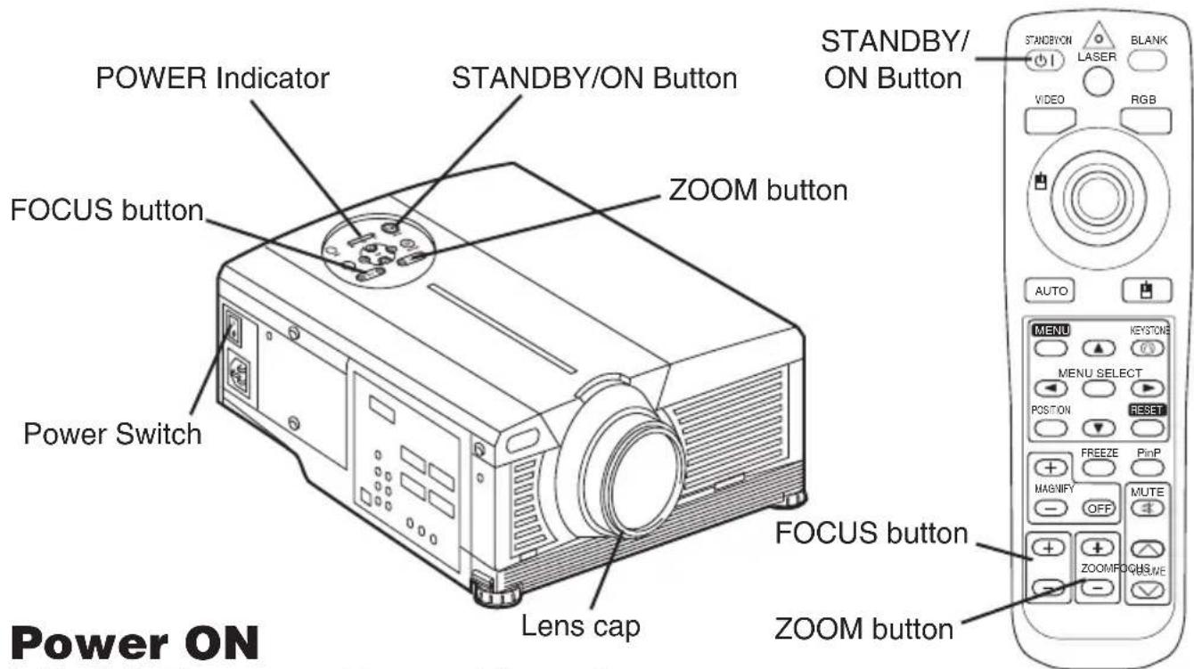
- Check that the power cord is connected correctly.
- Set the power switch to [ | ]. The standby mode is selected, and the POWER indicator is turned to orange.
- Press the STANDBY/ON button on the control panel or the remote control transmitter. Warm-up begins and the POWER indicator blinks in green.
- The POWER indicator ceases blinking and turns to green when power is on. Remove the lens cap.
- Adjust picture size using the ZOOM button.
- Adjust focus using the FOCUS button.
Power OFF
- Press the STANDBY/ON button on the control panel or the remote control transmitter. Then, the message "Power off?" will appear on the screen, and the message will disappear by any operation or no operation for 5 seconds. During this message indication, press the STANDBY/ON button again. The projector lamp is extinguished and lamp cooling begins. The POWER indicator blinks orange during lamp cooling. Pressing the STANDBY/ON button has no effect while the POWER indicator is blinking.
- The system assumes the Standby mode when cooling is complete, and the POWER indicator ceases blinking and changes to orange. Check that the indicator is orange and set the Power switch to [O].
- The POWER indicator is extinguished when power is off. Attach the lens cap.
WARNING • Please read this manual, and the separate “SAFETY INSTRUCTIONS” thoroughly before using the equipment. Always ensure that the equipment is used safely.
NOTE • Except in emergencies, follow the above-mentioned procedure for turning power off. Incorrect procedure will reduce the life of the projector lamp and LCD panel.
• To prevent any trouble, turn on/off the projector when the computer or video tape recorder is OFF. Providing a RS-232C cable is connected, turn on the computer before the projector.
- When a projector continues projecting the same image, the image may remain as an afterimage. Please do not project the image same for a long time.
Basic Operation
The basic operations shown in Table 3 is performed from the supplied remote control transmitter or the projector control panel. Items indicated by (*) may be used from the control panel.
Table 3. Basic Operation
| Item Description | |
| INPUT SELECT | Select Input Signal (*) : Press the INPUT button.RGB IN 1 →RGB IN 2 →DVI→ VIDEO → S-VIDEO → COMPONENT VIDEO (→ RGB IN 1)Select RGB Input : Press the RGB button.VIDEO/S-VIDEO/COMPONENT VIDEO →RGB IN 1/RGB IN 2/DVIRGB IN 1 → RGB IN 2 → DVI (→ RGB IN 1)Select Video Input : Press the VIDEO button.RGB IN 1/RGB IN 2/DVI →VIDEO/S-VIDEO/COMPONENT VIDEOVIDEO → S-VIDEO → COMPONENT VIDEO (→ VIDEO)The selected signal name is displayed for approximately 3 seconds when the input signal is changed. |
| POSITION | Set/Clear Position Adjustment Mode : Press the POSITION button.The [Fcon is displayed in the POSITION mode.Image Position Adjustment: Press the , and buttons in the POSITION mode.Valid only in the MAGNIFY mode with a video signal is input.After approximately 10 seconds of inactivity the [Fcon is extinguished and the POSITION mode is cleared automatically.and , and buttons may operate as the mouse control button. Refer to page 4. |
| RESET (*) | Initialise Each Item : Select an item and press the RESET button.Initialise Position Adjustment : Press the RESET button and the POSITION mode. This function is valid only when RGB signal is input.Valid except for the VOLUME, LANGUAGE, WHISPER and H PHASE.The RESET button may operate as the mouse control button. Refer to page 4. |
| MAGNIFY | Set MAGNIFY Mode : Press the MAGNIFY Button.Move Magnified Area : Run the POSITION in the MAGNIFY mode.Adjust Magnification : Press the MAGNIFY Button in MAGNIFY mode.Clear MAGNIFY Mode : Press the MAGNIFY Button.The MAGNIFY mode is cleared by running or setting the AUTO, ASPECT, INPUT SELECT or VIDEO, or by changing the input signal. |
| FREEZE | Set/Clear FREEZE Mode : Press the FREEZE button. The [II] icon is displayed, and the image frozen, in the FREEZE mode.The FREEZE mode is cleared by running or setting POSITION, VOLUME, MUTE, Automatic Adjustment, BLANK ON/OFF, or MENU ON/OFF, or by changing the input signal.Do not forget to clear frozen static images. |
NOTE • Use the remote control transmitter at a distance of approximately 5m from the sensor on the front of the projector, and within a range of 30^ left-right. Strong light and obstacles will interfere with operation of the remote control transmitter.
Items indicated by (*) may be used from the control panel.
Table 3. Basic Operation (continued)
| Item Description | |
| VOLUME | Volume Adjustment:Press the VOLUME 📧 / 🕒 button. |
| MUTE | Set/Clear Mute Mode:Press the MUTE button. No sound is heard in the MUTE mode. |
| AUTO | Automatic Adjustment at RGB Input:Press the AUTO button. Horizontal position(H.POSIT), vertical position (V.POSIT),clock phase (H.PHASE), and horizontal size(H.SIZE) are automatically adjusted. Use with the window at maximum size in the application display.Automatic Adjustment at Video Input:Press the AUTO button. A signal type appropriate for the input signal is selected automatically. Valid only when AUTO is set for VIDEO on the menu.This operation requires approximately 10 seconds. It may not function correctly with some input signals. |
| BLANK ON/OFF | Set/Clear Blank Mode:Press the BLANK button. No image is displayed in the Blank mode. The screen color is as set in BLANK on the Image menu. |
| MENU ON/OFF (*) | Menu Display Start/Stop:Press the MENU button.The menu display is terminated automatically after approximately 10 seconds of inactivity. |
| MENU SELECT | Select Menu Type:Press the MENU SELECT button. Allows the user to select the normal menu or the single menu. Only the selected item is displayed on the single menu, and other items are displayed with the ⚠ and buttons as with the normal menu.Valid only when the Setup menu is used. Push the MENU SELECT button after selecting items such as "BRIGHTNESS".The MENU SELECT button may operate as the mouse control button. Refer to page 4.Normal menu Single menu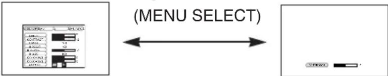 |
| P.IN P. MODE | Select Mode of P.IN P. Display:Press the PinP button.Small → Large → P.IN P. off ( → Small)Valid only at RGB IN 1, RGB IN 2 or DVI input. |
| ZOOM (*) | Adjust Screen Size:Press the ZOOM 📄 button. |
| FOCUS (*) | Adjust Focus:Press the FOCUS 📄 button. |
| KEYSTONE (*) | Set / Clear KEYSTONE Mode:Press the KEYSTONE button.Select KEYSTONE Mode:Press the ⚠ button in the KEYSTONE mode.Vertical 📄 ↔ HorizontalAdjust KEYSTONE:Press the 📄 button. |
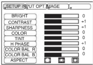
Setup Menu
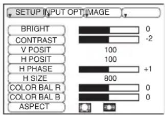
The following adjustments and settings are possible when SETUP is selected at the top of the menu. Part of the Setup menu differs between RGB input and video input. Select an item with the and buttons, and start operation. Use the Single menu to reduce menu size (see Table 3, MENU SELECT).
RGB IN 1 RGB IN 2 DVI
| Item Description | RGB IN 1 RGB IN 2 | DVI | VIDEO S-VIDEO COMPONENT | |
| BRIGHT | Adjustment: Dark Light | √√√ | ||
| CONTRAST | Adjustment: Weak Strong | √√√ | ||
| V POSIT | Adjustment: Down Up | √ | - | - |
| H POSIT | Adjustment: Left Right | √ | - | - |
| H PHASE | Adjustment: Left Right• Adjust to eliminate flicker. | √ | - | √ |
| H SIZE | Adjustment: Small ↔ Large• The image may not be displayed correctly if the horizontal size is excessive. In such cases, press the RESET button, and initialize the horizontal size. | √ | - | - |
| SHARPNESS | Adjustment: Soft Clear | - | - | √ |
| COLOR | Adjustment: Light ↔ Dark | - | - | √ |
| TINT | Adjustment: Red ↔ Green• Valid only when NTSC or NTSC 4.43 signal is received. | - | - | √ |
| COLOR BAL R | Adjustment: Light ↔ Dark | √√√ | ||
| COLOR BAL B | Adjustment: Light ↔ Dark | √√√ | ||
| ASPECT | Select Image Aspect Ratio :4:3[ ] ↔ 16:9[ ]Select Position of Image:Press the button while 16:9[ ] is selected.Center → Down → Up (→ Center) | √ | √ | - |
| Select Image Aspect Ratio:4:3[ ] ↔ 16:9[ ] ↔ 4:3 small[ ]Select Position of Image :Press the button while 16:9[ ] / 4:3 small[ ] is selected.Center → Down → Up (→ Center)• 4:3 small cannot be selected with the input of 720P or 1080i component.• 4:3 small may not be displayed correctly with some input signals. | - | - | √ | |
Input Menu
The following functions are available when INPUT is selected on the menu. Select an item with the and buttons, and start or stop operation with the and buttons. The function indicated (**) are effective on video input mode only, not on RGB input mode, except in the P.IN P. window on RGB input mode.
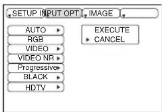
Table 5. Input Menu
| Item Description | |
| AUTO | Automatic Adjustment at RGB Input: Select the EXECUTE with the button. Horizontal position (H.POSIT), vertical position (V.POSIT), clock phase (H.PHASE), and horizontal size (H.SIZE) are automatically adjusted. Use with the window at maximum size in the application display.Automatic Adjustment at Video Input: Select the EXECUTE with the button. A signal type appropriate for the input signal is selected automatically when EXECUTE is selected automatically. Valid only when AUTO is set for VIDEO on the menu.This operation requires approximately 10 seconds. It may not function correctly with some input signals. Pressing the AUTO button in this case may correct this problem.This function is the same as for the AUTO function in Basic operation. |
| RGB | Displays RGB Input Frequency: Displays the horizontal and vertical sync signal frequencies for RGB input.Valid only at RGB input. |
| VIDEO (**) | Select Video Signal Type: Select the signal type with the and buttons. Select NTSC, PAL, SECAM, NTSC4.43, M-PAL, or N-PAL as appropriate for the input signal. The selection of AUTO enables and executes the function AUTO (Automatic Adjustment at Video Input), except for the N-PAL input.Use this function when the image becomes unstable (eg. the image becomes irregular, or lacks color) at VIDEO/S-VIDEO input.Automatic Adjustment requires approximately 10 seconds. It may not function correctly with some input signals. Pressing the AUTO button in this case may correct this problem except for the N-PAL input.For the COMPONENT VIDEO input, this function is not effective and the signal type is distinguished automatically. Refer to the item HDTV of the OPT. Menu for the signal of HDTV. |
| VIDEO NR (**) | Set/Clear Noise Reduction Mode: Select the TURN ON / TURN OFF with the / button. When the TURN ON is selected, the NR mode is active and the noise on screen of the video input will be reduced.Valid except for the HDTV. |
| Progressive (**) | Select Progressive Mode: Select the mode suitable for the input signal with the and buttons. The TV mode and the FILM mode convert the interlaced video signal into the progressive signal. The FILM mode is adptable 2-3 Pull-Down system to the conversion.Use this function to raise resolution, at the interlaced video input except HDTV signal. |
| BLACK(**) | Set/Clear Black Enhancement Mode: Select the TURN ON / TURN OFF with the / button. When the TURN ON is selected, the black enhancement mode is active and the contrast ratio of the screen for the video input will be raised by making black level darker. |
| HDTV (**) | Select HDTV mode: Select the 1035i mode or 1080i mode suitable for the input signal with the / button. |
Image Menu
The following adjustments and settings are available when IMAGE is selected on the menu. Select an item with the and buttons, and start or stop operation with the and buttons.
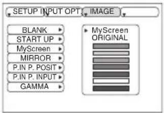
Table 6. Image Menu
| Item Description | |
| BLANK | Select Blank Screen: Select the screen in case of the BLANK mode with the 📁 / 📅 button. The selected one (MyScreen, ORIGINAL or one colors) is displayed when the BLANK mode is ON.MyScreenis a mode that the customer-customized screen is displayed. This is the blue screen at the factory setting. Refer to the description of MyScreen below.ORIGINALis a mode that the factory fixed screen is displayed.• When MyScreen or ORIGINAL is selected, the screen is going to the black after several minutes. |
| START UP | Select Start Up Screen: Select the screen in case of no signal input with the 📁 📅 button. The selected one (MyScreen, ORIGINAL or TURN OFF) is displayed when no signal is inputMyScreenis a mode that the customer-customized screen is displayed. This is the blue screen at the factory setting. Refer to the description of MyScreen below.ORIGINALis a mode that the factory fixed screen is displayed.TURN OFFdisplays the blue screen.• When MyScreen or ORIGINAL is selected, the screen is going to the black after several minutes. |
| MyScreen | Set MyScreen Mode: Select the EXECUTE with the button to display the MyScreen menu and set the MyScreen mode for BLANK and START UP functions.ESCclears and closes the menu box.NORM.is default of the MyScreen menu.FREEZEfreezes the image and displays the frame to capture.Press the 📋 button after freeze to go to the MyScreen Capture Position mode.In the MyScreen Capture Position mode, the buttons 📋, 📁, 📄 and ▶ allow to move the frame to capture.After adjusting the position, press the KEYSTONE button to go to the MyScreen Display Size mode.To cancel freezing and return to the NORM. of the MyScreen menu, press the RESET button.In the MyScreen Display Size mode, select the magnification x1, x2 or FULL with the button 📋/ 📋.After selecting the magnification, press the KEYSTONE button to go to the CAPT. mode and start capturing.To return to the MyScreen Capture Position mode, press the RESET button.CAPT.executes a capturing the image. It requires about 20 seconds. After capturing, the captured image will be displayed for about 10 seconds. |
| MIRROR | Select Mirror Status: Select mirror status with 📁 / 📅 button. |
| P. IN P. POSIT | Select Position of P. in P. Display : Press the 📋/ button.☐ 📁 ⇔ 📋 ☐ 📁 ⇔ 📋 ☐ 📁 ⇔ 📋 ☐• Valid only at RGB IN 1, RGB IN 2 or DVI input. |
| P. IN P. INPUT | Select signal of P. in P. Display : Press the 📋/ button.VIDEO 📁 ⇔ 📋 S-VIDEO 📁 ⇔ 📋 COMPONENT |
| GAMMA | Select Gamma Mode: Select the gamma mode with the 📁 / 📅 button.NORMAL 📁 ⇔ 📋 CINEMA 📁 ⇔ 📋 DYNAMIC |
Options Menu
The following adjustments and settings are available when OPT. is selected on the menu. Select an item with the and buttons, and start operation.
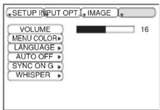
Table 7. Options Menu
| Item Description | |
| VOLUME | Volume Adjustment: Reduce VOLUME ⇌ Increase VOLUME |
| MENU COLOR | Select Menu Background Color: Select with the and buttons. |
| LANGUAGE | Operation Start/Stop: Press the button.Select Menu Display Language: Select with the and buttons. |
| AUTO OFF | Operation Start/Stop: Press the button.Set AUTO OFF: Set 1~99 minutes with the and buttons. The system automatically enters the standby mode when a signal is not received for the set time.Clear AUTO OFF: Select STOP (0 min.) with the button. When STOP is selected the system does not enter the standby mode even if no signal is received. |
| SYNC ON G | Operation Start/Stop: Press the button.SYNC ON G Valid: Select TURN ON with the button.SYNC ON G Invalid: Select TURN OFF with the button.May not be displayed correctly with some input signals when SYNC ON G is valid. In such cases, remove the signal connector so that no signal is received, set SYNC ON G to invalid, and reconnect the signal. |
| WHISPER | Set / Crear WHISPER Mode: Press the button. When the WHISPER is selected, the WHISPER mode is active. In the WHISPER mode, acoustic noise level from the unit is reduced, and brightness level on screen is a little lower. |
No Signal Menu
The same adjustments and settings are available as with the Image and Options menus when the MENU button is pressed during display of the “NO INPUT IS DETECTED ON ***” or “SYNC IS OUT OF RANGE ON ***” message while no signal is received.
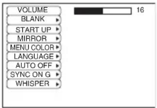
Table 8. No Signal Menu
| Item Description | |
| VOLUME | Volume Adjustment: Reduce VOLUME ⇌ Increase VOLUME • When this function is used, audio input is automatically switched to video. The audio input can be switched by moving the DISK PAD left and right during the display of the volume adjustment bar. The volume adjustment bar is displayed by pressing VOLUME or VOLUME button. |
| BLANK | Select Blank Screen: Select the screen in case of the BLANK mode with the / button. The selected one (MyScreen, ORIGINAL or one colors) is displayed when the BLANK mode is ON.MyScreen is a mode that the customer-customized screen is displayed. This is the blue screen at the factory setting. Refer to the description of MyScreen below.ORIGINAL is a mode that the factory fixed screen is displayed.• When MyScreen or ORIGINAL is selected, the screen is going to the black after several minutes. |
| START UP | Select Start Up Screen: Select the screen in case of no signal input with the / button. The selected one (MyScreen, ORIGINAL or TURN OFF) is displayed when no signal is inputMyScreen is a mode that the customer-customized screen is displayed. This is the blue screen at the factory setting. Refer to the description of MyScreen below.ORIGINAL is a mode that the factory fixed screen is displayed.TURN OFF displays the blue screen.• When MyScreen or ORIGINAL is selected, the screen is going to the black after several minutes. |
| MIRROR | Operation Start/Stop: Press the button.Select Mirror Status: Select the mirror status with the and buttons. |
| MENU COLOR | Select Menu Background Color: Select the color with the and buttons. |
| LANGUAGE | Operation Start/Stop: Press the button.Select Menu Display Language: Select the language with the and buttons. |
| AUTO OFF | Operation start/stop: Press the button.Set AUTO OFF: Set 1~99 minutes with the and buttons. The system automatically enters the standby mode when a signal is not received for the set time.Clear AUTO OFF: Select the STOP (0 min.) with the button. When the STOP is selected the system does not enter the standby mode even if no signal is received. |
| SYNC ON G | Operation Start/Stop: Press the button.SYNC ON G Valid: Select the TURN ON with the button.SYNC ON G Invalid: Select the TURN OFF with the button.• May not be displayed correctly with some input signals when the SYNC ON G is valid. In such cases, remove the signal connector so that no signal is received, set the SYNC ON G to invalid, and reconnect the signal. |
| WHISPER | Set / Crear WHISPER Mode: Press the button. When the WHISPER is selected, the WHISPER mode is active. In the WHISPER mode, acoustic noise level from the unit is reduced, and brightness level on screen is a little lower. |
Lamp

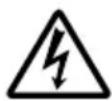


HIGH VOLTAGE HIGH TEMPERATURE HIGH PRESSURE
Contact your dealer before replacing the lamp.
For the optional lamp, see the item “Option Parts” of the Table 12.
Before replacing the lamp, switch power OFF, remove the power cord from the power outlet, and wait approximately 45 minutes until the lamp has cooled. The lamp may explode if handled at high temperatures.

WARNING • For disposal of used lamp, treat according to the instruction of community priorities.
- Since the lamp is made of glass, do not apply shock to it and do not scratch it.
- Also, do not use old lamp. This could also cause explosion of the lamp.
- Premature lamp failure MAY be caused by an electronic component in the projector and not necessarily the lamp. If unsure contact your local service center.
- If it is probable that the lamp has exploded (explosive sound is heard), disconnect the power plug from the power outlet and ask your dealer to replace lamp. The lamp is covered by front glass, but, in rare cases, the reflector and the inside of the projector may be damaged by scattered broken pieces of glass, and broken pieces could cause injury when being handled.
- Do not use the projector with the lamp cover removed.
Lamp
Lamp Life
Projector lamps have a finite life. The image will become darker, and hues will become weaker, after a lamp has been used for a long period of time.
Replace the lamp if the LAMP indicator is red, or the CHANGE THE LAMP message appears when the projector is switched ON. See Table 9 of P.20 and Table 10 of P.21.
NOTE • The LAMP indicator is also red when the lamp unit reaches high temperature. Before replacing the lamp, switch power OFF, wait approximately 20 minutes, and switch power ON again. If the LAMP indicator is still red, replace the lamp.
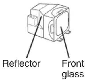
Replacing the Lamp
- Switch the projector OFF, remove the power cord from the power outlet, and wait at least 45 minutes for the unit to cool.
- Prepare a new lamp.
- Check that the projector has cooled sufficiently, and gently turn it upside down.
- Loosen the screw as shown in the diagram, and remove the lamp cover.
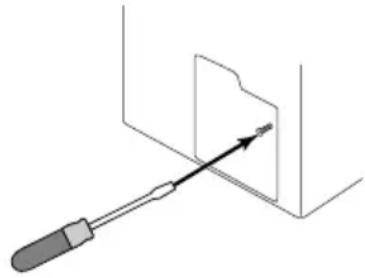
- Loosen the two screws, and gently remove the lamp while holding the grips. Touching the inside of the lamp case may result in uneven coloring.
- Install the new lamp and tighten the two screws firmly. Also steadily push the opposite side of the screwed lamp into the unit.
- Replace the lamp cover in position and tighten the screw firmly.
- Gently turn the projector right-side up.
natural_image
Diagram showing a screwdriver inserted into a folder with an arrow indicating direction (no text or symbols present)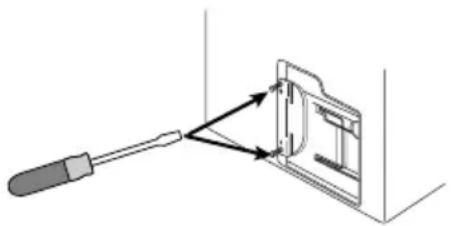
natural_image
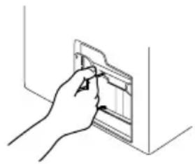
Diagram showing a screwdriver interacting with a device panel, no text or symbols presentCAUTION • Ensure that screws are tightened properly. Screws not tightened fully may result in injury or accidents.
- Do not use the projector with the lamp cover removed.
natural_image
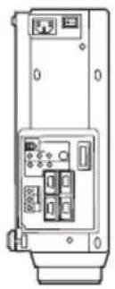
Line drawing of a hand inserting a card into a folder (no text or symbols)Resetting the Lamp Timer
Reset the lamp timer after replacing the lamp. When the lamp has been replaced after the LAMP indicator is red, or the CHANGE THE LAMP message is displayed, complete the following operation within ten minutes of switching power ON. The power will be turned off automatically in over 10 minutes.
- Switch power ON, and press the RESET button, for approximately three seconds. The 'LAMP xxxx hr' message will appear on the lamp timer on the bottom of the screen.
- Press the MENU button on the remote control transmitter, or the RESET button on the control panel, while the lamp timer is displayed. The 'LAMP xxxx □ →0 ■CANCEL' message will then appear.
- Press the and select 0, and wait until the timer display is cleared.
NOTE • Do not reset the lamp timer without replacing the lamp. Reset the lamp timer always when replacing the lamp. The message functions will not operate properly if the lamp timer is not reset correctly.
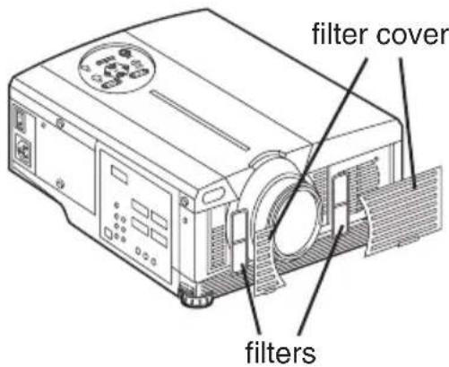
Air Filters
Cleaning Air Filters
This projector uses 2 air filters. These air filters should be cleaned as described below at intervals of approximately 100 hours.
- Switch the projector power supply OFF, and remove the power cord from the power outlet.
- Remove the filter cover and the air filter.
- Clean the air filter with a vacuum cleaner.
- Set the air filter and the filter cover.
Replacing the Air Filter
Replace the air filter if contamination cannot be removed, or if it is damaged.
- Switch the projector power supply OFF, and remove the power cord from the power outlet.
- Remove the filter cover and the old filter.
- Set the new filter and the filter cover.

CAUTION • Switch power OFF and remove the power cord from the power outlet before beginning maintenance work. Please read the separate “SAFETY TRUCTIONS” thoroughly to ensure that maintenance is performed correctly.
- Replace the air filter if contamination cannot be removed, or if it is damaged. Contact your dealer in such case. For the optional air filter, see the item “Option Parts” of the Table 12.
- Do not use the equipment with the air filter removed.
- When the air filter is clogged with dust etc. the power supply is switched OFF automatically to prevent the temperature rising inside the projector.
Other Maintenance
Maintenance Inside the Equipment
For safety reasons, ensure that the equipment is cleaned and checked by the dealer once every two years. Maintaining the equipment by yourself is dangerous.
Cleaning the Lens
Gently wipe the lens with lens cleaning paper. Do not touch the lens with your hands.
Cleaning the Cabinet and Remote control transmitter
Gently wipe with a soft cloth. If dirt and stains etc. are not easily removed, use a soft cloth dampened with water, or water and a neutral detergent, and wipe dry with a soft, dry cloth.

CAUTION • Switch power OFF and remove the power cord from the power outlet before beginning maintenance work. Please read the separate “SAFETY TRUCTIONS” thoroughly to ensure that maintenance is performed correctly.
- Do not use detergents or chemicals other than those noted above (e.g. benzene or thinners).
- Do not use cleaning sprays.
- Do not rub with hard materials, or tap the equipment.
OSD Message
The messages as described below may appear on the screen at power ON. Take the appropriate measures when such messages appears.
Table 9. OSD Messages
| Message Contents | |
| CHANGE THE LAMP AFTER REPLACING LAMP, RESET THE LAMP TIME. (*1) | The usage time of lamp will be reaching 2000 hr shortly. 2It is recommended to replace the lamp soon. Prepare a new lamp as a replacement. |
| CHANGE THE LAMP AFTER REPLACING LAMP, RESET THE LAMP TIME. THE POWER WILL TURN OFF AFTER ** hr. (*1) | The usage time of lamp will be reaching 2000 hr shortly. It is recommended to replace the lamp within * * hours. 2It might be happened that the lamp is cut off before * * hr by any chance. Power will be switched OFF automatically in * * hours. Replace the lamp as shown in P.17~18 “Lamp”. Always reset the lamp timer after replacing the lamp. |
| CHANGE THE LAMP AFTER REPLACING LAMP, RESET THE LAMP TIME. THE POWER WILL TURN OFF AFTER 0 hr. | The usage time of lamp is about to reach. Power will be switched OFF in a few minutes. 2Switch power OFF immediately and replace the lamp as shown in P.17 ~18 “Lamp”. Always reset the lamp timer after replacing the lamp. |
| NO INPUT IS DETECTED ON *** | No input signal found.Check signal input connections and signal sources. |
| SYNC IS OUT OF RANGE ON *** | The horizontal or vertical frequency of the input signal is not within the specified range.Check the specifications of the equipment and the signal source. |
| CHECK THE AIR FLOW | The internal temperature has risen.Switch power OFF, and wait 20 minutes until the equipment cools.Check the following and Switch power ON again.* Are the ventilation openings blocked.* Is the air filter dirty.* Is the ambient temperature in excess of 35°C. |
NOTE (*1) This message is cleared automatically after approximately three minutes, and appears every time power is switched ON.
(*2) The unit has a function to turn the power off which will be active when the usage time reaches 2000 hr. However the life of lamp might be much different among lamps, so that it might be happened that a lamp is cut off before the function is active.
Indicators Message
The POWER indicator, LAMP indicator, and TEMP indicator are lit and blank as follows. Take the appropriate measures.
Table 10. Indicators Message
| POWER indicator | LAMP indicator | TEMP indicator | Contents |
| Lights orange | Turns off | Turns off | The Standby mode has been set. |
| Blinks green | Turns off | Turns off | Warming up. Please wait. |
| Lights green | Turns off | Turns off | ON. Normal operation possible. |
| Blinks orange | Turns off | Turns off | Cooling. Please wait. |
| Lights red | Lights red | Turns off | Lamp is not lit.The interior of the equipment may be too hot. Switch power OFF, wait 20 minutes until the equipment cools, and check whether the ventilation openings are blocked, whether the air filter is dirty, or whether the ambient temperature exceeds 35 °C. And switch power ON again. Replace the lamp if the same problem occurs. |
| Lights red | Blinks red | Turns off | Lamp or lamp cover is not found, or hasn't been fitted in correctly.Switch power OFF, and wait for 45 minutes until the equipment cools. Check fitting of the lamp and lamp cover, and switch power ON again. Contact your dealer if the same problem occurs again. |
| Lights red | Turns off | Blinks red | The cooling fan is not operating.Switch power OFF, and wait for 20 minutes until the equipment cools. Check for foreign matters in the fan, and switch power ON again. Contact your dealer if the same problem occurs again. |
| Lights red | Turns off | Lights red | The interior of the equipment is too hot.Switch power OFF, and wait for 20 minutes until the equipment cools. Check whether the ventilation openings are blocked, whether the air filter is dirty, or whether the ambient temperature exceeds 35 °C. Then switch power ON again. Contact your dealer if the same problem occurs again. |
NOTE When the internal temperature becomes excessive power is switched OFF automatically for safety reasons, and the indicator is extinguished. Set the power switch to [O] and wait for 20 minutes until the equipment has cooled sufficiently.
Symptom
Before requesting repair, check in accordance with the following chart. If the situation cannot be corrected, then contact your dealer.
Table 11. Symptom
| Symptom Possible cause Remedy Page | |||
| The power is not turned on. | The main power switch is not turned on. | Turn on the main power switch. | 8,9 |
| The power cord is disconnected. | Plug the power cord into an AC power outlet. | ||
| No video or audio. | The input is not correctly set. | Use the projector or remote control transmitter to set. | 10 |
| No signal input. Connect correctly. | 7,8 | ||
| Video is present but no audio. | The projector is not correctly connected. | Connect correctly. | 7,8 |
| The volume is set to minimum. | Press VOLUME on the remote control or display the menu screen and adjust the volume. | 11,15 | |
| Mute is turned on. | Press the MUTE button. | 11 | |
| Audio is present but no video. | The projector is not correctly connected. | Connect correctly. | 7,8 |
| The brightness adjustment knob is rotated fully clockwise. | Select BRIGHT with the MENU button and the press the button. | 12 | |
| The lens cap is still attached. Remove the lens cap. | 9 | ||
| Colors are pale and color matching is poor. | Color density and color matching are not correctly adjusted. | Adjust the video. | 12 |
| Images are dark. | Brightness and contrast are not correctly adjusted. | Adjust the video. | 12 |
| The lamp is nearing the end of its service life. | Replace with a new lamp. | 17 | |
| Video is blurred. | Focus or H PHASE is out of adjustment. | Adjust the focus or H PHASE. | 9,12 |
Table 12. Specifications
| Item Specification | |||
| Product name Liquid crystal projector | |||
| Liquid crystal panel | Panel size 3.3 cm (1.3 type) | ||
| Drive system TFT active matrix | |||
| Pixels 786,432 pixels (1024 horizontal x 768 vertical) | |||
| Lens Zoom lens F=1.7 ~ 2.3 f=49 | 0 ~ 64.0 mm | ||
| Lamp 275 W UHB | |||
| Speaker 1.2 W + 1.2W (Stereo) | |||
| Power supply AC100 ~ 120V, 4.7A / AC220 ~ 240V, 2.0A | |||
| Power consumption 440W | |||
| Temperature range 0 ~ 35°C (Operating) | |||
| Size 289 (W) x 144 (H) x 350 (D) mm | |||
| Weight (mass) 6.5 kg | |||
| RGB signal input | RGB IN | 1 | Video: Analog 0.7Vp-p, 75Ωterminator (positive)H/V. sync.: TTL level (positive/negative)Composite sync.: TTL levelD-sub 15-pin shrink jack |
| 2 | |||
| DVI | TMDS, DC: 150~1200 mV / AC: 1.56 Vp-pTTL Level (Positive/Negative) | ||
| AUDIO IN | RGB1 | 200mVrms, 50 kΩ(max. 3.0Vp-p)Stereo mini jack | |
| DVI | |||
| RGB2 | |||
| Video signal input | VIDEO | 1.0Vp-p, 75ΩterminatorRCA jack | |
| S-VIDEO | Brightness signal: 1.0Vp-p, 75ΩterminatorColor signal: 0.286Vp-p (burst signal), 75ΩterminatorMini DIN 4-pin jack | ||
| COMPONENTVIDEO | Y 1.0 | Vp-p, 75 ΩTerminator (Positive) | |
| CB/CR | 0.7 Vp-p, 75 Ω Terminator (Positive) | ||
| PB/PR | 0.7 Vp-p, 75 Ω Terminator (Positive) | ||
| AUDIO | L/MONO | 200mVrms, 50 kΩ(max. 3.0Vp-p)RCA jack | |
| R | |||
| Signal output | RGB OUT | Video: Analog 0.7Vp-p, 75Ωoutput impedance (positive)H/V. sync.: TTL level (positive/negative)Composite sync.: TTL levelD-sub 15-pin shrink jack | |
| AUDIO OUT | 200mVrms, output impedance 1 kΩ(max. 3.0Vp-p)Stereo mini jack | ||
| Control functions | CONTROL | D-sub 15-pin shrink plug | |
| USB | USB jack (B type) | ||
| Optional Parts | Lamp: DT00491Air Filter: MN04531* For others, consult your dealer. | ||
NOTE • This specifications are subject to change without notice.
WARRANTY AND AFTER-SERVICE
If a problem occurs with the equipment, first refer to the P.20 “TROUBLESHOOTING” section and run through the suggested checks. If this does not resolve the problem contact your dealer or service company. They will tell you what warranty condition is applied.
Dimension Diagram
natural_image
Technical line drawing of a device rear panel with ports and connectors (no text or symbols)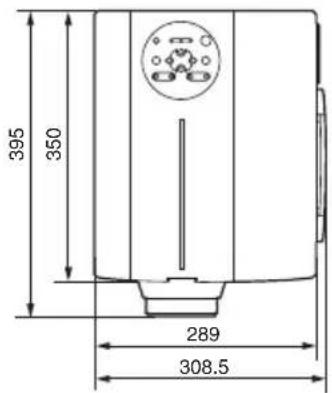
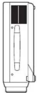
natural_image
Line drawing of a mechanical device with no visible text or symbols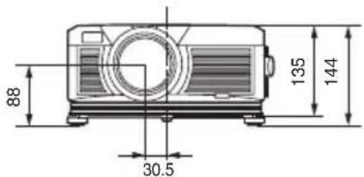
Unit : mm
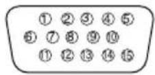
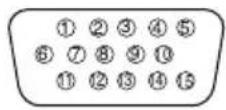
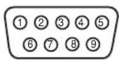
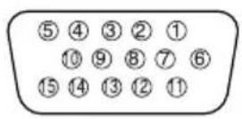
Signal Connector Pin Assignment
1. D-sub 15-pin Shrink Connector (RGB IN 1/RGB IN 2/RGB OUT)
| Pin No | Signal | Pin No | Signal | Pin No | Signal |
| 1 Video input Red | 9 | - | 15 | RGB IN 1: SCL(DDC) | |
| 2 | Video input Green | 10 | Ground | RGB IN 2: - | |
| 3 | Video input Blue | 11 | - | RGB OUT: - | |
| 4 | - | 12 RGB OUT: - | RGB IN 1: SDA(DDC) | 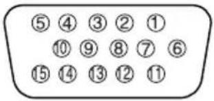 | |
| 5 Ground | B IN 2: - | ||||
| 6 Ground Red | B OUT: - | ||||
| 7 Ground Green | 13 | H. sync./ Composite sync. | |||
| 8 Ground Blue | 14 Vertical sync | ||||
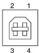
2. Digital Receptacle Connector (DVI)
| Pin No | Signal Pin No Signal Pin No Signal | ||||
| 1 | T.M.D.S. Data 2 - | 11 | T.M.D.S. Data 1 / 3 Shield | 21 | - |
| 2 | T.M.D.S. Data 2 + | 12 | - | 22 | T.M.D.S. Clock Shield |
| 3 | T.M.D.S. Data 2 / 4 Shield | 13 | - | 23 | T.M.D.S. Clock + |
| 4 - 14 | +5V Power 24 T.M.D.S. Clock - | ||||
| 5 - 15 | Ground (+5V, Analog H/V Sync.) | 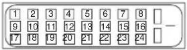 | |||
| 6 | DDC Clock | 16 | Hot-Plug Sense | ||
| 7 DDC Data 17 T.M.D.S. Data 0 - | |||||
| 8 | Analog V. Sync. | 18 | T.M.D.S. Data 0 + | ||
| 9 | T.M.D.S. Data 1 - | 19 | T.M.D.S. Data 0 / 5 Shield | ||
| 10 T.M.D.S. Data 1 + 20 - | |||||
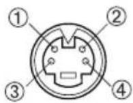
3. Mini Din 4-pin Connector (S-VIDEO)
| Pin No | Signal |
| 1 | Color:0.286Vp-p (NTSC, burst signal),75Ω terminator0.3Vp-p (PAL/SECAM, burst signal),75Ω terminator |
| 2 | Brightness:1.0Vp-p, 75Ω terminator |
| 3 | Ground |
| 4 | Ground |
Example of computer signal
| Resolution H ×V | fH (kHz) fV | (Hz) Rating | Signal mode | Display mode | |
| 720 ×400 | 37.9 85.0 | VESA TEXT | Zoom in | ||
| 640 ×480 | 31.5 59.9 | VESA VGA | (60Hz) | Zoom in | |
| 640 ×480 | 35.0 66.7 | Mac1 | 3"mode Zoom in | ||
| 640 ×480 | 37.9 72.8 | VESA VGA | (72Hz) | Zoom in | |
| 640 ×480 | 37.5 75.0 | VESA VGA | (75Hz) | Zoom in | |
| 640 ×480 | 43.3 85.0 | VESA VGA | (85Hz) | Zoom in | |
| 800 ×600 | 35.2 | 56.3 | VESA | SVGA (56Hz) | Zoom in |
| 800 ×600 | 37.9 | 60.3 | VESA | SVGA (60Hz) | Zoom in |
| 800 ×600 | 48.1 | 72.2 | VESA | SVGA (72Hz) | Zoom in |
| 800 ×600 | 46.9 | 75.0 | VESA | SVGA (75Hz) | Zoom in |
| 800 ×600 | 53.7 | 85.1 | VESA | SVGA (85Hz) | Zoom in |
| 832 ×624 | 49.7 74.5 | Mac1 | 6"mode Zoom in | ||
| 1024 ×768 | 48.4 60.0 | VESA XGA | (60Hz) | ||
| 1024 ×768 | 56.5 70.1 | VESA XGA | (70Hz) | ||
| 1024 ×768 | 60.0 75.0 | VESA XGA | (75Hz) | ||
| 1024 ×768 | 68.7 85.0 | VESA XGA | (85Hz) | ||
| 1152 ×864 | 67.5 | 75.0 | VESA | SXGA (75Hz) | Zoom out |
| 1280 ×960 | 60.0 | 60.0 | VESA | SXGA (60Hz) | Zoom out |
| 1280 ×1024 | 64.0 | 60.0 | VESA | SXGA (60Hz) | Zoom out |
| 1280 ×1024 | 80.0 | 75.0 | VESA | SXGA (75Hz) | Zoom out |
| 1600 ×1200 | 75.0 | 60.0 | VESA | VXGA (60Hz) | Zoom out |
NOTE • Some computers may have multiple display screen modes. Use of some of these modes will not be possible with this projector.
- Be sure to check jack type, signal level, timing and resolution before connecting this projector to a computer.
- Depending on the input signal, full-size display may not be possible in some cases. Refer to the number of display pixels above.
- The image may not be displayed correctly when the input sync. signal is "Composite Sync." or "Sync. on G".
- The image might be something wrong with computer by computer on the DVI mode. In the case, it is recommended to reduce the resolution and / or refresh rate.
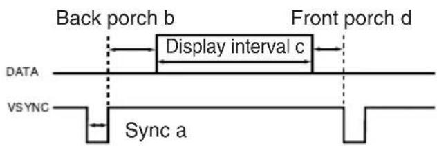
Initial set signals
The following signals are used for the initial settings.
The signal timing of some computer models may be different. In such case, refer to adjust the V.POSIT and H.POSIT of the menu.
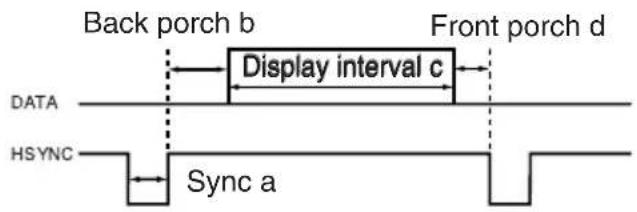
| Computer / Signal | Horizontal signal timing (μs) | |||
| a | b | c | d | |
| TEXT 2.0 3.0 | 20.3 | 1 | 0 | |
| VGA (60Hz) 3.8 | 1.9 | 25. | 4 | 0.6 |
| Mac 13"mode 2.1 | 3.2 | 21 | .2 | 2.1 |
| VGA (72Hz) 1.3 | 3.8 | 20. | 3 | 1.0 |
| VGA (75Hz) 2.0 | 3.8 | 20. | 3 | 0.5 |
| VGA (85Hz) 1.6 | 2.2 | 17. | 8 | 1.6 |
| SVGA (56Hz) 2.0 | 3.6 | 22 | .2 | 0.7 |
| SVGA (60Hz) 3.2 | 2.2 | 20 | .0 | 1.0 |
| SVGA (72Hz) 2.4 | 1.3 | 16 | .0 | 1.1 |
| SVGA (75Hz) 1.6 | 3.2 | 16 | .2 | 0.3 |
| SVGA (85Hz) 1.1 | 2.7 | 14 | .2 | 0.6 |
| Mac 16"mode 1.1 | 3.9 | 14 | .5 | 0.6 |
| XGA (60Hz) 2.1 | 2.5 | 15 | .8 | 0.4 |
| XGA (70Hz) 1.8 | 1.9 | 13 | .7 | 0.3 |
| XGA (75Hz) 1.2 | 2.2 | 13 | .0 | 0.2 |
| XGA (85Hz) 1.0 | 2.2 | 10 | .8 | 0.5 |
| 1152×864 (75Hz) | 1.2 | 2.4 | 10.7 | 0.6 |
| 1280×960 (60Hz) | 1.0 | 2.9 | 11.9 | 0.9 |
| 1280×1024 (60Hz) | 1.0 | 2.3 | 11.9 | 0.4 |
| 1280×1024 (75Hz) | 1.1 | 1.8 | 9.5 | 0.1 |
| 1600×1200 (60Hz) | 1.2 | 1.9 | 9.9 | 0.4 |
| Computer / Signal | Vertical signal timimg (lines) | |||
| a b c d | ||||
| TEXT | 3 | 42 | 400 | 1 |
| VGA (60Hz) | 2 | 33 | 480 | 10 |
| Mac 13"mode | 3 | 39 | 480 | 3 |
| VGA (72Hz) | 3 | 28 | 480 | 9 |
| VGA (75Hz) | 3 | 16 | 480 | 1 |
| VGA (85Hz) | 3 | 25 | 480 | 1 |
| SVGA (56Hz) | 2 | 22 | 600 | 1 |
| SVGA (60Hz) | 4 | 23 | 600 | 1 |
| SVGA (72Hz) | 6 | 23 | 600 | 37 |
| SVGA (75Hz) | 3 | 21 | 600 | 1 |
| SVGA (85Hz) | 3 | 27 | 600 | 1 |
| Mac 16"mode | 3 | 39 | 624 | 1 |
| XGA (60Hz) | 6 | 29 | 768 | 3 |
| XGA (70Hz) | 6 | 29 | 768 | 3 |
| XGA (75Hz) | 3 | 28 | 768 | 1 |
| XGA (85Hz) | 3 | 36 | 768 | 1 |
| 1152×864 (75Hz) | 3 | 32 864 | 1 | |
| 1280×960 (60Hz) | 3 | 36 960 | 1 | |
| 1280×1024 (60Hz) | 3 | 38 1024 1 | ||
| 1280×1024 (75Hz) | 3 | 38 1024 1 | ||
| 1600×1200 (60Hz) | 3 | 46 1200 1 | ||
Connection to the Mouse Control
1. PS/2, ADB or Serial Mouse
(1) Turn off the projector and computer, and connect the two units with the appropriate cable. For PS/2 mouse control (for IBM and compatible), use the enclosed mouse cable. For others, consult your dealer.
(2) Disconnect the USB cable from the projector if it is connected. Then turn on the projector.
(3) Turn on the computer.
(4) Start the mouse function. If the mouse has not been started, reboot the computer (soft reboot or reboot buttons). Refer to the descriptions of “DISC PAD” and “MOUSE/RIGHT button” of page 4.
2. USB Mouse
(1) Connect the projector and computer with a suitable commercially available USB cable. Consult your dealer to get the cable, if you need.
(2) Start the mouse function. Refer to the descriptions of "DISC PAD" and "MOUSE/RIGHT button" of page 4.
NOTE • Before connecting, read the instruction manuals of the devices to be connected. • In the case of notebook type computers with an internal pointing device, the mouse control function will not work unless the internal pointing device is disabled. In such case, disable the internal pointing device and change the BIOS setting to select an external mouse before the operations described in (1) to (4) above.
Also, some computers may not have a utility program to operate a mouse.
Refer to the computer hardware manual for detail.
PS/2 Mouse
CONTROL Terminal
D-sub 15-pin shrink jack
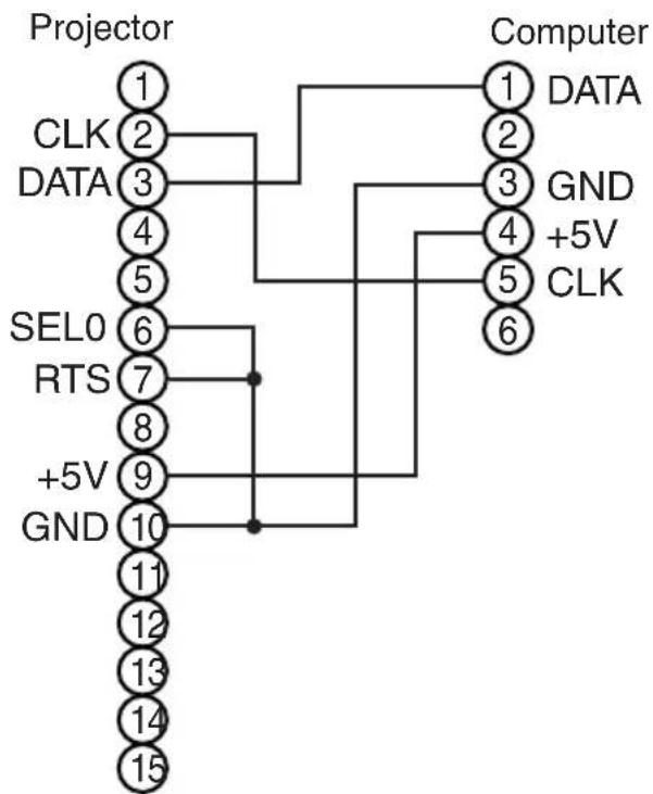
flowchart
graph TD
    A["Projector"] --> B["1 CLK"]
    A --> C["2 DATA"]
    A --> D["3"]
    A --> E["4"]
    A --> F["5"]
    A --> G["6"]
    A --> H["7"]
    A --> I["8"]
    A --> J["9"]
    A --> K["10"]
    A --> L["11"]
    A --> M["12"]
    A --> N["13"]
    A --> O["14"]
    A --> P["15"]
    Q["Computer"] --> R["1 DATA"]
    Q --> S["2 GND"]
    Q --> T["3 +5V"]
    Q --> U["4 CLK"]
    Q --> V["5"]
    Q --> W["6"]
Mouse jack
Mini DIN 6-pin
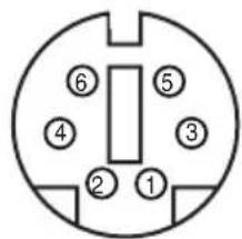
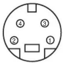
ADB Mouse
CONTROL Terminal
D-sub 15-pin shrink jack
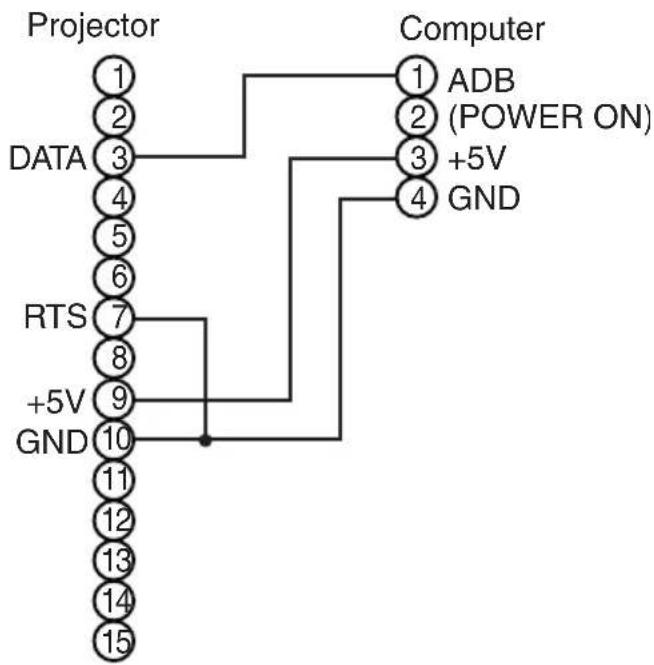
flowchart
graph TD
    A["Projector"] --> B["DATA"]
    B --> C["RTS"]
    C --> D["+5V"]
    D --> E["GND"]
    E --> F["Computer"]
    F --> G["ADB (POWER ON)"]
    G --> H["+5V"]
    H --> I["GND"]
Mouse jack Mini DIN 4-pin
Serial Mouse
CONTROL Terminal
D-sub 15-pin shrink jack
flowchart
graph TD
    A["Projector"] --> B["1"]
    A --> C["2"]
    A --> D["3"]
    A --> E["4"]
    A --> F["5"]
    A --> G["6"]
    A --> H["7"]
    A --> I["8"]
    A --> J["9"]
    A --> K["GND"]
    K --> L["10"]
    K --> M["11"]
    K --> N["12"]
    K --> O["13"]
    K --> P["14"]
    K --> Q["15"]
    R["Computer"] --> S["1"]
    R --> T["2"]
    R --> U["3"]
    R --> V["4"]
    R --> W["5"]
    R --> X["6"]
    R --> Y["7"]
    R --> Z["8"]
    R --> AA["9"]
    R --> AB["CTS"]
    R --> AC["RI"]
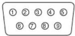
Mouse jack D-sub 9-pin
USB Mouse
USB jack (B type)
Projector Computer
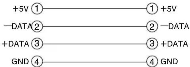
flowchart
graph LR
    A["+5V ①"] --> B["① +5V"]
    C["-DATA ②"] --> D["② DATA"]
    E["+DATA ③"] --> F["③ +DATA"]
    G["GND ④"] --> H["④ GND"]
USB jack (A type)
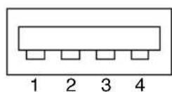
USB cable
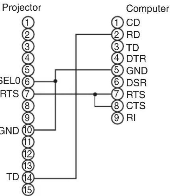
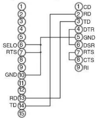
RS-232C communication
(1) Turn off the projector and computer power supplies and connect with the RS-232C cable.
(2) Turn on the computer power supply and, after the computer has started up, turn on the projector power supply.
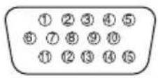
Control jack
D-sub 15-pin shrink jack
Projector Computer
flowchart
graph TD
    A["1"] --> B["SELO"]
    C["2"] --> B
    D["3"] --> B
    E["4"] --> B
    F["5"] --> B
    G["6"] --> B
    H["7"] --> B
    I["8"] --> B
    J["9"] --> B
    K["GND"] --> B
    L["10"] --> B
    M["11"] --> B
    N["12"] --> B
    O["RD"] --> P["TD"]
    Q["13"] --> P
    R["14"] --> P
    S["15"] --> P
    T["1"] --> U["CD"]
    V["2"] --> U
    W["3"] --> U
    X["4"] --> Y["DTR"]
    Z["5"] --> Y
    AA["6"] --> AB["GND"]
    AC["7"] --> AD["DSR"]
    AE["8"] --> AF["RTS"]
    AG["9"] --> AH["CTS"]
    AI["10"] --> AJ["RI"]
RS-232C jack D-sub 9-pin
Communications setting
19200bps, 8N1
1 Protocol
Consist of header (7 bytes) + command data (6 bytes).
2 Header
BE + EF + 03 + 06 + 00 + CRC_low + CRC_high
CRC_low : Lower byte of CRC flag for command data.
CRC_high : Upper byte of CRC flag for command data.
3 Command data
Command data chart
| byte_0 byte_1 byte_2 | byte_3 byte_4 byte_5 | ||
| Action Type Setting code | |||
| low high low high low high | |||
Action (byte_0 - 1)
| Action Classification | Content | |
| 1 | SET | Change setting to desired value. |
| 2 | GET | Read projector internal setup value. |
| 4 | INCREMENT | Increment setup value by 1. |
| 5 | DECREMENT | Decrement setup value by 1. |
| 6 | EXECUTE | Run a command. |
Requesting projector status (Get command)
(1) Send the request code Header + Command data ('02H' + '00H' + type (2 bytes) + '00H' + '00H') from the computer to the projector.
(2) The projector returns the response code '1DH' + data (2 bytes) to the computer.
Changing the projector settings (Set command)
(1) Send the setting code Header + Command data ('01H' + '00H' + type (2 bytes) + setting code (2 bytes)) from the computer to the projector.
(2) The projector changes the setting based on the above setting code.
(3) The projector returns the response code '06H' to the computer.
Using the projector default settings (Reset Command)
(1) The computer sends the default setting code Header + Command data ('06H' + '00H' + type (2 bytes) + '00H' + '00H') to the projector.
(2) The projector changes the specified setting to the default value.
(3) The projector returns the response code '06H' to the computer.
Increasing the projector setting value (Increment command)
(1) The computer sends the increment code Header + Command data ('04H' + '00H' + type (2 bytes) + '00H' + '00H') to the projector.
(2) The projector in creases the setting value on the above setting code.
(3) The projector returns the response code '06H' to the computer.
Decreasing the projector setting value (Decrement command)
(1) The computer sends the decrement code Header + Command data ('05H' + '00H' + type (2 bytes) + '00H' + '00H') to the projector.
(2) The projector decreases the setting value on the above setting code.
(3) The projector returns the response code '06H' to the computer.
When a command sent by the projector cannot be understood by the computer
When the command sent by the projector cannot be understood, the error command '15H' is returned by the computer. Some times, the projector ignores RS-232C commands during other works. If the error command '15H' is returned, please send the same command again.
When data sent by the projector cannot be practice
When the command sent by the projector cannot be practiced, the error code '1cH' + 'xxxxH' is returned.
When the data length is greater than indicated by the data length code, the projector will ignore the excess data code.
Conversely, when the data length is shorter than indicated by the data length code, an error code will be returned to the projector.
NOTE • Operation cannot be guaranteed when the projector receives an undefined command or data.
- Provide an interval of at least 40ms between the response code and any other code.
- The projector outputs test data when the power supply is switched ON, and when the lamp is lit. Ignore this data.
- Commands are not accepted during warm-up.
Command data chart
| Names Operation type Header | Command data | |||||||||
| CRC Action Type Setting code | ||||||||||
| Blank Color | Set | Red | BE EF | 03 | 06 00 | 3B D3 | 01 00 | 00 30 | 00 00 | |
| Orange | BE EF | 03 | 06 00 | AB D2 | 01 00 | 00 30 | 01 00 | |||
| Green | BE EF | 03 | 06 00 | 5B D2 | 01 00 | 00 30 | 02 00 | |||
| Blue | BE EF | 03 | 06 00 | CB D3 | 01 00 | 00 30 | 03 00 | |||
| Purple | BE EF | 03 | 06 00 | FB D1 | 01 00 | 00 30 | 04 00 | |||
| White | BE EF | 03 | 06 00 | 6B D0 | 01 00 | 00 30 | 05 00 | |||
| Black | BE EF | 03 | 06 00 | 9B D0 | 01 00 | 00 30 | 06 00 | |||
| MyScreen | BE EF | 03 | 06 00 | FB CA | 01 00 | 00 30 | 20 00 | |||
| ORIGINAL | BE EF | 03 | 06 00 | FB E2 | 01 00 | 00 30 | 40 00 | |||
| Get | BE EF | 03 | 06 00 | 08 D3 | 02 00 | 00 30 | 00 00 | |||
| Mirror | Set | Normal | BE EF | 03 | 06 00 | C7 D2 | 01 00 | 01 30 | 00 00 | |
| H Inverse | BE EF | 03 | 06 00 | 57 D3 | 01 00 | 01 30 | 01 00 | |||
| V Inverse | BE EF | 03 | 06 00 | A7 D3 | 01 00 | 01 30 | 02 00 | |||
| H&V Inverse | BE EF | 03 | 06 00 | 37 D2 | 01 00 | 01 30 | 03 00 | |||
| Get | BE EF | 03 | 06 00 | F4 D2 | 02 00 | 01 30 | 00 00 | |||
| Freeze | Set | Normal | BE EF | 03 | 06 00 | 83 D2 | 01 00 | 02 30 | 00 00 | |
| Freeze | BE EF | 03 | 06 00 | 13 D3 | 01 00 | 02 30 | 01 00 | |||
| Get | BE EF | 03 | 06 00 | B0 D2 | 02 00 | 02 30 | 00 00 | |||
| Menu Color | Set | Red | BE EF | 03 | 06 00 | 7F D3 | 01 00 | 03 30 | 00 00 | |
| Orange | BE EF | 03 | 06 00 | EF D2 | 01 00 | 03 30 | 01 00 | |||
| Green | BE EF | 03 | 06 00 | 1F D2 | 01 00 | 03 30 | 02 00 | |||
| Blub | BE EF | 03 | 06 00 | 8F D3 | 01 00 | 03 30 | 03 00 | |||
| Purple | BE EF | 03 | 06 00 | BF D1 | 01 00 | 03 30 | 04 00 | |||
| Transparent | BE EF | 03 | 06 00 | 2F D0 | 01 00 | 03 30 | 05 00 | |||
| Gray | BE EF | 03 | 06 00 | DF D0 | 01 00 | 03 30 | 06 00 | |||
| Get | BE EF | 03 | 06 00 | 4C D3 | 02 00 | 03 30 | 00 00 | |||
| Startup | Set | ORIGINAL | BE EF | 03 | 06 00 | 0B D2 | 01 00 | 04 30 | 00 00 | |
| OFF | BE EF | 03 | 06 00 | 9B D3 | 01 00 | 04 30 | 01 00 | |||
| MyScreen | BE EF | 03 | 06 00 | CB CB | 01 00 | 04 30 | 20 00 | |||
| Get | BE EF | 03 | 06 00 | 38 D2 | 02 00 | 04 30 | 00 00 | |||
| Language | Set | English | BE EF | 03 | 06 00 | F7 D3 | 01 00 | 05 30 | 00 00 | |
| Français | BE EF | 03 | 06 00 | 67 D2 | 01 00 | 05 30 | 01 00 | |||
| Deutsch | BE EF | 03 | 06 00 | 97 D2 | 01 00 | 05 30 | 02 00 | |||
| Español | BE EF | 03 | 06 00 | 07 D3 | 01 00 | 05 30 | 03 00 | |||
| Italiano | BE EF | 03 | 06 00 | 37 D1 | 01 00 | 05 30 | 04 00 | |||
| Norsk | BE EF | 03 | 06 00 | A7 D0 | 01 00 | 05 30 | 05 00 | |||
| Nederlands | BE EF | 03 | 06 00 | 57 D0 | 01 00 | 05 30 | 06 00 | |||
| Português | BE EF | 03 | 06 00 | C7 D1 | 01 00 | 05 30 | 07 00 | |||
| Japanese | BE EF | 03 | 06 00 | 37 D4 | 01 00 | 05 30 | 08 00 | |||
| Get | BE EF | 03 | 06 00 | C4 D3 | 02 00 | 05 30 | 00 00 | |||
Command data chart
| Names Operation type Header | Command data | |||||||||
| CRC Action Type Setting code | ||||||||||
| Magnify | Get | BE EF | 03 | 06 00 | 7C D2 | 02 00 | 07 30 | 00 00 | ||
| Increment | BE EF | 03 | 06 00 | 1A D2 | 04 00 | 07 30 | 00 00 | |||
| Decrement | BE EF | 03 | 06 00 | CB D3 | 05 00 | 07 30 | 00 00 | |||
| Auto off | Get | BE EF | 03 | 06 00 | 08 86 | 02 00 | 10 31 | 00 00 | ||
| Increment | BE EF | 03 | 06 00 | 6E 86 | 04 00 | 10 31 | 00 00 | |||
| Decrement | BE EF | 03 | 06 00 | BF 87 | 05 00 | 10 31 | 00 00 | |||
| Brightness Reset | Execute | BE EF | 03 | 06 00 | 58 D3 | 06 00 | 00 70 | 00 00 | ||
| Contrast Reset | Execute | BE EF | 03 | 06 00 | A4 D2 | 06 00 | 01 70 | 00 00 | ||
| V.Position Reset | Execute | BE EF | 03 | 06 00 | E0 D2 | 06 00 | 02 70 | 00 00 | ||
| H.Position Reset | Execute | BE EF | 03 | 06 00 | IC D3 | 06 00 | 03 70 | 00 00 | ||
| H.Size Reset | Execute | BE EF | 03 | 06 00 | 68 D2 | 06 00 | 04 70 | 00 00 | ||
| Color Balance R Reset | Execute | BE EF | 03 | 06 00 | 94 D3 | 06 00 | 05 70 | 00 00 | ||
| Color Balance B Reset | Execute | BE EF | 03 | 06 00 | D0 D3 | 06 00 | 06 70 | 00 00 | ||
| Sharpness Reset | Execute | BE EF | 03 | 06 00 | C4 D0 | 06 00 | 09 70 | 00 00 | ||
| Color Reset | Execute | BE EF | 03 | 06 00 | 80 D0 | 06 00 | 0A 70 | 00 00 | ||
| Tint Reset | Execute | BE EF | 03 | 06 00 | 7C D1 | 06 00 | 0B 70 | 00 00 | ||
| Keystone_V Reset | Execute | BE EF | 03 | 06 00 | 08 D0 | 06 00 | 0C 70 | 00 00 | ||
| Keystone_H Reset | Execute | BE EF | 03 | 06 00 | 98 D8 | 06 00 | 20 70 | 00 00 | ||
| Auto | Execute | BE EF | 03 | 06 00 | 91 D0 | 06 00 | 0A 20 | 00 00 | ||
| Blank on/off | Set | off | BE EF | 03 | 06 00 | FB D8 | 01 00 | 20 30 | 00 00 | |
| on | BE EF | 03 | 06 00 | 6B D9 | 01 00 | 20 30 | 01 00 | |||
| Get | BE EF | 03 | 06 00 | C8 D8 | 02 00 | 20 30 | 00 00 | |||
| Error Status | Get | BE EF | 03 | 06 00 | D9 D8 | 02 00 | 20 60 | 00 00 | ||
| (Example of Return) | ||||||||||
| 00 00 | 01 00 | 02 00 | 03 00 | |||||||
| (Normal) (Cover-error) (Fan-error) (Lamp-error) | ||||||||||
| 04 00 | 05 00 | 06 00 | ||||||||
| (Temp-error) (Air flow-error) (Lamp-Time-over) | ||||||||||
| Power | Set | OFF | BE EF | 03 | 06 00 | 2A D3 | 01 00 | 00 60 | 00 00 | |
| ON | BE EF | 03 | 06 00 | BA D2 | 01 00 | 00 60 | 01 00 | |||
| Get | BE EF | 03 | 06 00 | 19 D3 | 02 00 | 00 60 | 00 00 | |||
| Input Source | Set | RGB1 | BE EF | 03 | 06 00 | FE D2 | 01 00 | 00 20 | 00 00 | |
| RGB2 | BE EF | 03 | 06 00 | 3E D0 | 01 00 | 00 20 | 04 00 | |||
| Digital | BE EF | 03 | 06 00 | 0E D2 | 01 00 | 00 20 | 03 00 | |||
| Video | BE EF | 03 | 06 00 | 6E D3 | 01 00 | 00 20 | 01 00 | |||
| SVideo | BE EF | 03 | 06 00 | 9E D3 | 01 00 | 00 20 | 02 00 | |||
| Component | BE EF | 03 | 06 00 | AE D1 | 01 00 | 00 20 | 05 00 | |||
| Get | BE EF | 03 | 06 00 | CD D2 | 02 00 | 00 20 | 02 00 | |||
| Volume | Get | BE EF | 03 | 06 00 | 31 D3 | 02 00 | 01 20 | 00 00 | ||
| Increment | BE EF | 03 | 06 00 | 57 D3 | 04 00 | 01 20 | 00 00 | |||
| Decrement | BE EF | 03 | 06 00 | 86 D2 | 05 00 | 01 20 | 00 00 | |||
Command data chart
| Names Operation type Header | Command data | |||||||||
| CRC Action Type Setting code | ||||||||||
| Mute | Set | Normal | BE EF | 03 | 06 00 | 46 D3 | 01 00 | 02 20 | 00 00 | |
| Mute | BE EF | 03 | 06 00 | D6 D2 | 01 00 | 02 20 | 01 00 | |||
| Get | BE EF | 03 | 06 00 | 75 D3 | 02 00 | 02 20 | 00 00 | |||
| Brightness | Get | BE EF | 03 | 06 00 | 89 D2 | 02 00 | 03 20 | 00 00 | ||
| Increment | BE EF | 03 | 06 00 | EF D2 | 04 00 | 03 20 | 00 00 | |||
| Decrement | BE EF | 03 | 06 00 | 3E D3 | 05 00 | 03 20 | 00 00 | |||
| Contrast | Get | BE EF | 03 | 06 00 | FD D3 | 02 00 | 04 20 | 00 00 | ||
| Increment | BE EF | 03 | 06 00 | 9B D3 | 04 00 | 04 20 | 00 00 | |||
| Decrement | BE EF | 03 | 06 00 | 4A D2 | 05 00 | 04 20 | 00 00 | |||
| Color Balance R | Get | BE EF | 03 | 06 00 | 01 D2 | 02 00 | 05 20 | 00 00 | ||
| Increment | BE EF | 03 | 06 00 | 67 D2 | 04 00 | 05 20 | 00 00 | |||
| Decrement | BE EF | 03 | 06 00 | B6 D3 | 05 00 | 05 20 | 00 00 | |||
| Color Balance B | Get | BE EF | 03 | 06 00 | 45 D2 | 02 00 | 06 20 | 00 00 | ||
| Increment | BE EF | 03 | 06 00 | 23 D2 | 04 00 | 06 20 | 00 00 | |||
| Decrement | BE EF | 03 | 06 00 | F2 D3 | 05 00 | 06 20 | 00 00 | |||
| Keystone_V | Get | BE EF | 03 | 06 00 | B9 D3 | 02 00 | 07 20 | 00 00 | ||
| Increment | BE EF | 03 | 06 00 | DF D3 | 04 00 | 07 20 | 00 00 | |||
| Decrement | BE EF | 03 | 06 00 | OE D2 | 05 00 | 07 20 | 00 00 | |||
| Keystone_H | Get | BE EF | 03 | 06 00 | E9 D0 | 02 00 | OB 20 | 00 00 | ||
| Increment | BE EF | 03 | 06 00 | 8F D0 | 04 00 | OB 20 | 00 00 | |||
| Decrement | BE EF | 03 | 06 00 | 5E D1 | 05 00 | OB 20 | 00 00 | |||
| Aspect | Set | 4:3 | BE EF | 03 | 06 00 | 9E D0 | 01 00 | 08 20 | 00 00 | |
| 16:9 | BE EF | 03 | 06 00 | OE D1 | 01 00 | 08 20 | 01 00 | |||
| Small | BE EF | 03 | 06 00 | FE D1 | 01 00 | 08 20 | 02 00 | |||
| Get | BE EF | 03 | 06 00 | AD D0 | 02 00 | 08 20 | 00 00 | |||
| Display Position at 16 : 9 or Small | Set | Default | BE EF | 03 | 06 00 | 62 D1 | 01 00 | 09 20 | 00 00 | |
| Bottom | BE EF | 03 | 06 00 | F2 D0 | 01 00 | 09 20 | 01 00 | |||
| Top | BE EF | 03 | 06 00 | 02 D0 | 01 00 | 09 20 | 02 00 | |||
| Get | BE EF | 03 | 06 00 | 51 D1 | 02 00 | 09 20 | 00 00 | |||
| V.Position | Get | BE EF | 03 | 06 00 | OD 83 | 02 00 | 00 21 | 00 00 | ||
| Increment | BE EF | 03 | 06 00 | 6B 83 | 04 00 | 00 21 | 00 00 | |||
| Decrement | BE EF | 03 | 06 00 | BA 82 | 05 00 | 00 21 | 00 00 | |||
| H.Position | Get | BE EF | 03 | 06 00 | F1 82 | 02 00 | 01 21 | 00 00 | ||
| Increment | BE EF | 03 | 06 00 | 97 82 | 04 00 | 01 21 | 00 00 | |||
| Decrement | BE EF | 03 | 06 00 | 46 83 | 05 00 | 01 21 | 00 00 | |||
| H.Size | Get | BE EF | 03 | 06 00 | B5 82 | 02 00 | 02 21 | 00 00 | ||
| Increment | BE EF | 03 | 06 00 | D3 82 | 04 00 | 02 21 | 00 00 | |||
| Decrement | BE EF | 03 | 06 00 | 02 83 | 05 00 | 02 21 | 00 00 | |||
| H.Phase | Get | BE EF | 03 | 06 00 | 49 83 | 02 00 | 03 21 | 00 00 | ||
| Increment | BE EF | 03 | 06 00 | 2F 83 | 04 00 | 03 21 | 00 00 | |||
| Decrement | BE EF | 03 | 06 00 | FE 82 | 05 00 | 03 21 | 00 00 | |||
Command data chart
| Names Operation type Header | Command data | |||||||||
| CRC Action Type Setting code | ||||||||||
| Sharpness | Get | BE EF 03 06 00 97 72 04 00 01 | F1 72 | 02 00 | 01 22 | 00 00 | ||||
| Increment BE EF | 03 06 00 97 72 04 00 01 | 22 00 00 | ||||||||
| Decrement BE EF | 03 06 00 46 73 05 00 01 | 22 00 00 | ||||||||
| Color | Get | BE EF 03 06 00 | B5 72 | 02 00 | 02 22 | 00 00 | ||||
| Increment | BE EF 03 06 00 | D3 72 | 04 00 | 02 22 | 00 00 | |||||
| Decrement BE EF | 03 06 00 02 73 05 00 02 | 22 00 00 | ||||||||
| Tint | Get | BE EF 03 06 00 | 49 73 | 02 00 | 03 22 | 00 00 | ||||
| Increment | BE EF 03 06 00 | 2F 73 | 04 00 | 03 22 | 00 00 | |||||
| Decrement | BE EF 03 06 00 | FE 72 | 05 00 | 03 22 | 00 00 | |||||
| Video Format | Set | Auto | BE EF 03 06 00 | 9E 75 | 01 00 | 00 22 | 0A 00 | |||
| NTSC | BE EF 03 06 00 | FE 71 | 01 00 | 00 22 | 04 00 | |||||
| PAL | BE EF 03 06 00 | 6E 70 | 01 00 | 00 22 | 05 00 | |||||
| SECAM | BE EF 03 06 00 | 6E 75 | 01 00 | 00 22 | 09 00 | |||||
| NTSC 4.43 | BE EF 03 06 00 | 5E 72 | 01 00 | 00 22 | 02 00 | |||||
| M-PAL | BE EF 03 06 00 | FE 74 | 01 00 | 00 22 | 08 00 | |||||
| N-PAL | BE EF 03 06 00 | 0E 71 | 01 00 | 00 22 | 07 00 | |||||
| Get | BE EF 03 06 00 | 0D 73 | 02 00 | 00 22 | 00 00 | |||||
| Video NR | Set | off | BE EF 03 06 00 | B6 73 | 01 00 | 06 22 | 00 00 | |||
| on | BE EF 03 06 00 | 26 72 | 01 00 | 06 22 | 01 00 | |||||
| Get | BE EF 03 06 00 | 85 73 | 02 00 | 06 22 | 00 00 | |||||
| Progressive | Set | off | BE EF 03 06 00 | 4A 72 | 01 00 | 07 22 | 00 00 | |||
| TV | BE EF 03 06 00 | DA 73 | 01 00 | 07 22 | 01 00 | |||||
| FILM | BE EF 03 06 00 | 2A 73 | 01 00 | 07 22 | 02 00 | |||||
| Get | BE EF 03 06 00 | 79 72 | 02 00 | 07 22 | 00 00 | |||||
| Black | Set | off | BE EF 03 06 00 | 5E 71 | 01 00 | 08 22 | 00 00 | |||
| on | BE EF 03 06 00 | CE 70 | 01 00 | 08 22 | 01 00 | |||||
| Get | BE EF 03 06 00 | 6D 71 | 02 00 | 08 22 | 00 00 | |||||
| HDTV | Set | 1080i | BE EF 03 06 00 | F2 73 | 01 00 | 05 22 | 00 00 | |||
| 1035i | BE EF 03 06 00 | 62 72 | 01 00 | 05 22 | 01 00 | |||||
| Get | BE EF 03 06 00 | C1 73 | 02 00 | 05 22 | 00 00 | |||||
| PinP Size | Set | off | BE EF 03 06 00 | FE 22 | 01 00 | 00 23 | 00 00 | |||
| Large | BE EF 03 06 00 | 6E 23 | 01 00 | 00 23 | 01 00 | |||||
| Small | BE EF 03 06 00 | 9E 23 | 01 00 | 00 23 | 02 00 | |||||
| Get | BE EF 03 06 00 | Cd 22 | 02 00 | 00 23 | 00 00 | |||||
Command data chart
| Names Operation type Header | Command data | |||||||||
| CRC A | Action Type | Setting code | ||||||||
| PinP Position | Set | Upper left | BE EF 03 06 00 | 02 23 | 01 00 | 01 23 | 00 00 | |||
| Upper right BE | EF 03 06 00 92 22 01 00 | 01 23 01 | 00 | |||||||
| bottom left BE | EF 03 06 00 62 22 01 00 | 01 23 03 | 00 | |||||||
| bottom right | BE EF 03 06 00 | F2 23 | 01 00 | 01 23 | 02 00 | |||||
| Get | BE EF 03 06 00 | 31 23 | 02 00 | 01 23 | 00 00 | |||||
| PinP Audio ch | Set | RGB | BE EF 03 06 00 | BA 22 | 01 00 | 03 23 | 00 00 | |||
| Video | BE EF 03 06 00 | 2A 23 | 01 00 | 03 23 | 01 00 | |||||
| Get | BE EF 03 06 00 | 89 22 | 02 00 | 03 23 | 00 00 | |||||
| PinP Input | Set | Video | BE EF 03 06 00 | D6 22 | 01 00 | 02 23 | 01 00 | |||
| S-Video | BE EF 03 06 00 | 26 22 | 01 00 | 02 23 | 02 00 | |||||
| Component | BE EF 03 06 00 | 16 20 | 01 00 | 02 23 | 05 00 | |||||
| Get | BE EF 03 06 00 | 75 23 | 02 00 | 02 23 | 00 00 | |||||
| FOCUS | Increment | BE EF 03 06 00 | 6A 93 | 04 00 | 00 24 | 00 00 | ||||
| Decrement | BE EF 03 06 00 | BB 92 | 05 00 | 00 24 | 00 00 | |||||
| Zoom | Increment | BE EF 03 06 00 | 96 92 | 04 00 | 01 24 | 00 00 | ||||
| Decrement | BE EF 03 06 00 | 47 93 | 05 00 | 01 24 | 00 00 | |||||
| Sync on G | Set | off | BE EF 03 06 00 | CB D0 | 01 00 | 08 30 | 01 00 | |||
| on | BE EF 03 06 00 | 5B D1 | 01 00 | 08 30 | 00 00 | |||||
| Get | BE EF 03 06 00 | 68 D1 | 02 00 | 08 30 | 00 00 | |||||
| WHISPER | Set | NORMAL | BE EF 03 06 00 | 3B 23 | 01 00 | 00 33 | 00 00 | |||
| WHISPER | BE EF 03 06 00 | AB 22 | 01 00 | 00 33 | 01 00 | |||||
| Get | BE EF 03 06 00 | 08 23 | 02 00 | 00 33 | 00 00 | |||||
| GAMMA | Set | NORMAL | BE EF 03 06 00 | C7 F0 | 01 00 | A1 30 | 00 00 | |||
| CINEMA | BE EF 03 06 00 | 57 F1 | 01 00 | A1 30 | 01 00 | |||||
| DYNAMIC | BE EF 03 06 00 | A7 F1 | 01 00 | A1 30 | 02 00 | |||||
| 6500K | BE EF 03 06 00 | 37 F0 | 01 00 | A1 30 | 03 00 | |||||
| Get | BE EF 03 06 00 | F4 F0 | 02 00 | A1 30 | 00 00 | |||||
FCC Statement Warning
WARNING: This equipment has been tested and found to comply with the limits for a Class B digital device, pursuant to Part 15 of the FCC Rules. These limits are designed to provide reasonable protection against harmful interference in a residential installation. This equipment generates, uses, and can radiate radio frequency energy and, if not installed and used in accordance with the instructions, may cause harmful interference to radio communications. However, there is no guarantee that interference will not occur in a particular installation. If this equipment does cause harmful interference to radio or television reception, which can be determined by turning the equipment off and on, the user is encouraged to try to correct the interference by one or more of the following measures:
- Reorient or relocate the receiving antenna.
- Increase the separation between the equipment and receiver.
- Connect the equipment into an outlet on a circuit different from that to which the receiver is connected.
- Consult the dealer or an experienced radio/TV technician for help.
INSTRUCTIONS TO USERS: This equipment complies with the requirements of FCC (Federal Communication Commission) equipment provided that the following conditions are met.
The cables may have to be used with the core set to the projector side. Use the cables which are included with the projector or specified.
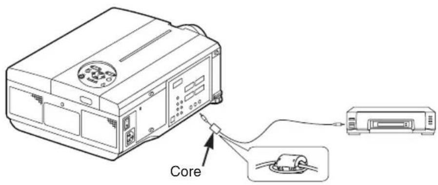
CAUTION: Changes or modifications not expressly approved by the party responsible for compliance could void the user's authority to operate the equipment.
For the Customers in CANADA
NOTICE: This Class B digital apparatus complies with Canadian ICES-003.
- BEDIENUNGSANLEITUNG
- HITACHI
- Liquid Crystal Projector
- USER'S MANUAL
- CONTENTS
- TABLES
- Outstanding Brightness
- Partial Magnification Function
- Distortion Correction Function
- BEFORE USE
- Contents of package
- Part Names
- Loading the Batteries
- Installation of the Projector and Screen
- Angle Adjustment
- Cabling
- Power Connection
- Example of system setup
- Plug & Play
- Power OFF
- Basic Operation
- Setup Menu
- Input Menu
- Image Menu
- Options Menu
- No Signal Menu
- Lamp
- HIGH VOLTAGE HIGH TEMPERATURE HIGH PRESSURE
- Lamp Life
- Replacing the Lamp
- CAUTION • Ensure that screws are tightened properly. Screws not tightened fully may result in injury or accidents.
- Resetting the Lamp Timer
- Air Filters
- Cleaning Air Filters
- Replacing the Air Filter
- Other Maintenance
- Maintenance Inside the Equipment
- Cleaning the Lens
- Cleaning the Cabinet and Remote control transmitter
- OSD Message
- Indicators Message
- Symptom
- WARRANTY AND AFTER-SERVICE
- Dimension Diagram
- Signal Connector Pin Assignment
- D-sub 15-pin Shrink Connector (RGB IN 1/RGB IN 2/RGB OUT)
- Digital Receptacle Connector (DVI)
- Mini Din 4-pin Connector (S-VIDEO)
- Initial set signals
- Connection to the Mouse Control
- PS/2, ADB or Serial Mouse
- USB Mouse
- PS/2 Mouse
- ADB Mouse
- Serial Mouse
- USB Mouse
- RS-232C communication
- Communications setting
- Protocol
- Header
- Command data
- Requesting projector status (Get command)
- Changing the projector settings (Set command)
- Using the projector default settings (Reset Command)
- Increasing the projector setting value (Increment command)
- Decreasing the projector setting value (Decrement command)
- When a command sent by the projector cannot be understood by the computer
- When data sent by the projector cannot be practice
- FCC Statement Warning
- For the Customers in CANADA
Brand : HITACHI
Model : CP-X990W
Category : Video projector