Vigor 6080 - Treadmills JKexer - Free user manual and instructions
Find the device manual for free Vigor 6080 JKexer in PDF.

User questions about Vigor 6080 JKexer
0 question about this device. Answer the ones you know or ask your own.
Ask a new question about this device
Download the instructions for your Treadmills in PDF format for free! Find your manual Vigor 6080 - JKexer and take your electronic device back in hand. On this page are published all the documents necessary for the use of your device. Vigor 6080 by JKexer.
USER MANUAL Vigor 6080 JKexer
natural_image
Black treadmill with visible brand logo and control panel, no text or symbols on the device itselfOwner's Manual
Made in Taiwan
TABLE OF CONTENTS
IMPORTANT SAFETY INSTRUCTIONS ...... P. 1
ELECTRICAL GROUNDING INSTRUCTION P. 2
ASSEMBLY LIST P. 3\~4
ASSEMBLY INSTRUCTIONS P. 5\~7
CLEANING AND INSPECTING THE RUNNING BELT ...... P. 16
CEANING.... P. 16
INSPECT FASTENERS AND WIRING P. 17
STORAGE P. 17
RUNNING BOARD MAINTENANCE ...... P. 17
HOW TO WORK OUT SAFELY AND EFFICIENTLY?...... P. 18
EXPLODED DRAWING.... P. 19
PARTS LIST (B.O.M.).... P. 20\~21
We reserve the right to make change at any time without notice, in colors, parts and materials.
IMPORTANT SAFETY INSTRUCTIONS
Please read the following basic precautions prior to use of the treadmill:
* Never operate the treadmill with the air openings blocked. Keep air openings free of lint, hair, and the like.
WARNING
* Always hold on the handlebar to keep balance and avoid slipping when walking in high gradient.
* Stand only on side rails when starting.
* Change speed in small increment.
* Push emergency stop while you feel uncomfortable.
* Never try to adjust or fix belt while it's moving.
* This treadmill requires a dedicated circuit as 110V/220V 15/10AMP separately that is not shared by any other electrical appliances. Failure to do so can damage the electronics and the motor, and will void the warranty.
* To reduce the risk of electric shock, always unplug the power cord from electrical outlet immediately after using and before cleaning, assembling or servicing.
*Never leave the treadmill unattended when plugged in. Disconnect by turning off the master power switch and unplugging from outlet.
* Always keep hands and feet off the treadmill while others are using it.
* Never place hands or feet under the treadmill.
* Do not allow children on or around treadmill.
CAUTIONS
* Never operate the treadmill if it has been dropped or damaged, or exposed to water. Contact our customer service department for service recommendations.
* Before starting any exercise program, it is recommended that you consult your physician.
* Stop using this appliance if you feel dizziness or discomfort.
* Medical approval and close supervision is necessary when appliance is used by or near handicapped individuals.
* Use the treadmill only for its intended use as described in this manual.
* Do not pull the treadmill by the power cord or use it as a handle.
* Keep power cord away from heated surfaces and open flame.
* Do not use or store outdoors.
* Do not operate where aerosol products are being used or where oxygen is being administered.
* While turning on the power, please stand beside the treadmill, not on the treadmill.
* The weight limit for both treadmills is 264LBS/120KGS.
* Do not operate in a wet or moist condition.
* Do not use the treadmill on a carpet that is greater than 1/2 inch in height.
* Do not operate under a blanket. Excessive heating can occur and cause fire, electrical shock, or injury to persons.
* Never insert any object into any openings on the treadmill.
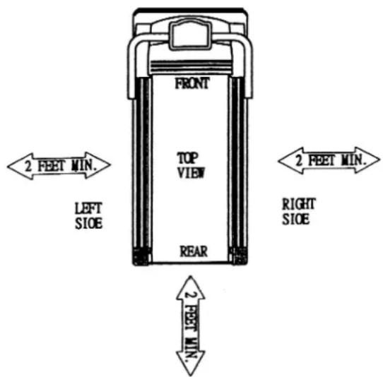
* Keep the treadmill on a solid, level surface with sides at least two feet from any wall. Be sure the area around the treadmill remains clear during use and has adequate clearance, see illustration below.
* Do not walk or jog barefoot or without shoes.
* Do not walk or jog in loose shoes or slippers. Athletic shoes are always recommended while using this treadmill.
* Never walk or jog while wearing loose fitting, long garments such as slacks pajamas or dresses.
* When walking or jogging always stay on the forward part of the treadmill.
* Never jog or walk faster than is comfortable for you.
* Do not jump up on the treadmill from side to side.
* Do not place any liquids on any parts of the treadmill.
* Do not plug into the same outlet with any other electrical appliance while using this treadmill.
ELECTRICAL GROUNDING INSTRUCTIONS
This product must be grounded. If it should malfunction or break down, grounding provides a path of least resistance for the electric current, reducing the risk of electric shock. This treadmill is equipped with a cord having an equipment grounding connector and a grounding plug. The plug must be plugged into an appropriate outlet that is properly installed and grounded in accordance with all local codes and ordinances.
DANGER
Improper connection of the treadmill grounding can result in the risk of electric shock. Check with a qualified electrician if you are in doubt as to whether the products is properly grounded. Do not modify the plug provided with the treadmill. If it will not fit your outlet, have a properly grounded outlet installed by a qualified electrician.
This unit must be plugged into a nominal 115 volt 60 Hz, 15 amp or 220 Volt, 50Hz 10AMP circuit, which has a grounding plug. Outlets that service multiple appliances,
or have fluctuating voltage of more than 5%, may result in erratic performance or cause damage to the treadmill electronics. Using electrical power other than that which has been specified will ultimately void any warranty, implied or otherwise.
Never remove or bypass the electrical ground contained in the treadmill's three-lug with an adapter.
The difference in the RPM of motor is ± 10%
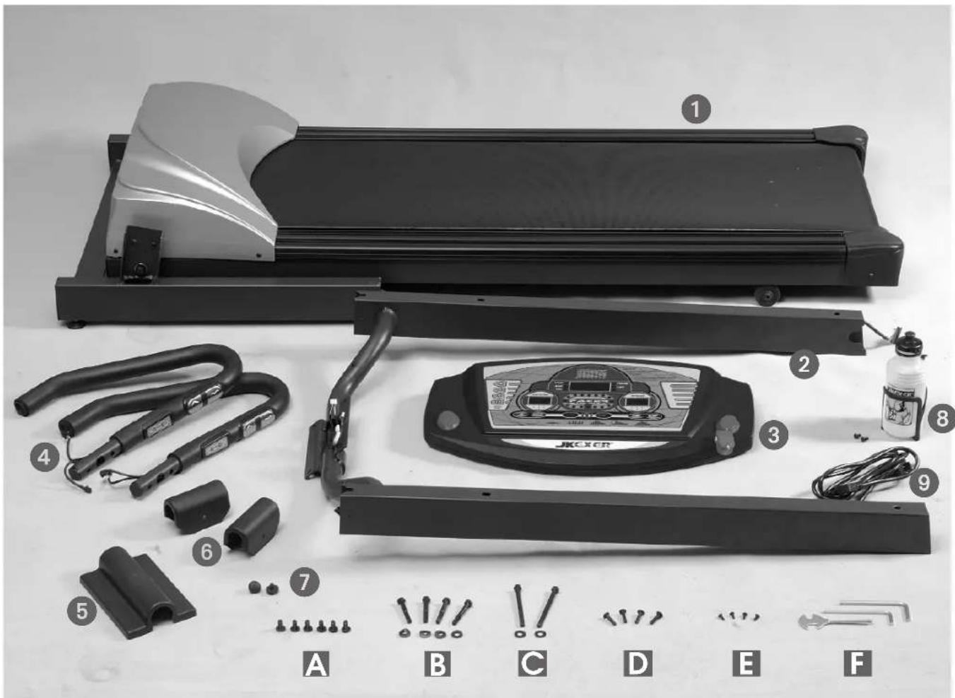
JK-6090 ASSEMBLY LIST
- MAIN FRAME .... 1
- FRONT POST .... 1
3.COMPUTER....1 - HANDLE BAR 2
- COMPUTER BACK COVER .... 1
- SIDE COVER 2
- RUBBER TIP 2
- BOTTLE SET .... 1
- POWER CABLE .... 1
A. BOLT 6
B. BOLT & WASHER 4+4
C. BOLT & WASHER 2+2
D. BOLT 4
E. BOLT 4
F. TOOLS 3
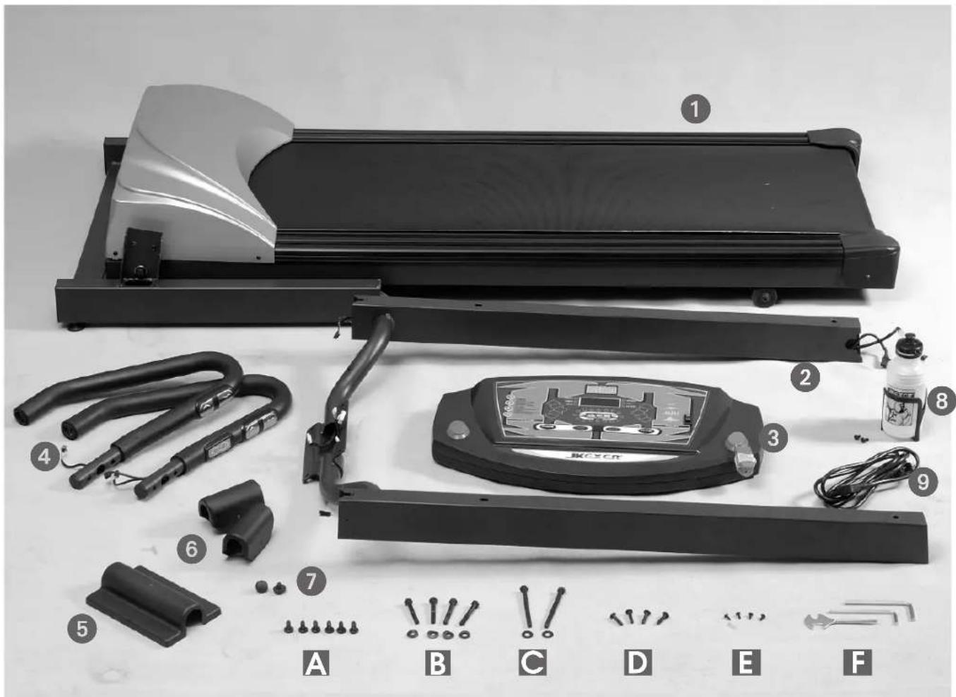
JK-6080 ASSEMBLY LIST
-
MAIN FRAME .... 1
-
FRONT POST .... 1
3.COMPUTER....1
-
HANDLE BAR 2
-
COMPUTER BACK COVER .... 1
-
SIDE COVER 2
-
RUBBER TIP 2
-
BOTTLE SET .... 1
-
POWER CABLE .... 1
A. BOLT 6
B. BOLT & WASHER 4+4
C. BOLT & WASHER 2+2
D. BOLT 4
E. BOLT 4
F. TOOLS 3
ASSEMBLY INSTRUCTION
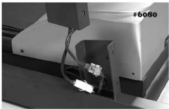
natural_image
Close-up of a mechanical device with wires and connectors, labeled #6080 (no readable text or symbols beyond label)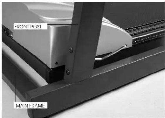
natural_image
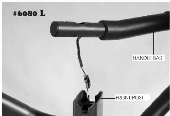
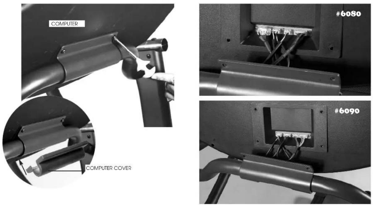
Close-up of a mechanical component with a black cable and connector, no visible text or symbolsSTEP 1:
CONNECT THE CABLES PROVIDED (ON THE RIGHT SIDE) FROM FRONT POST AND MAIN FRAME, THEN INSERT FRONT POST INTO MAIN FRAME AND PLEASE NOTE NOT TO CUT THE WIRES. FIXED WITH BOLT (A). 3 BOLTS ON LEFT AND 3 ON RIGHT SIDE, DO NOT TIGHTEN UNTIL ALL 6 BOLTS ARE SCREWED IN.
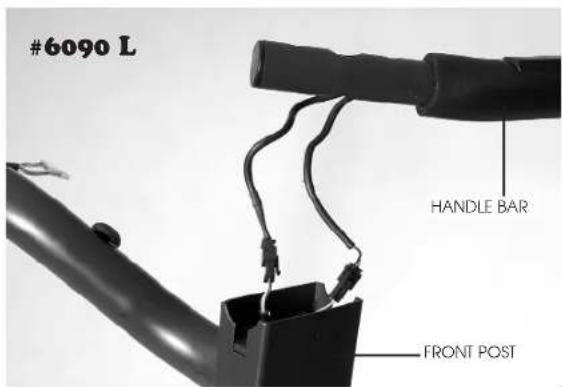
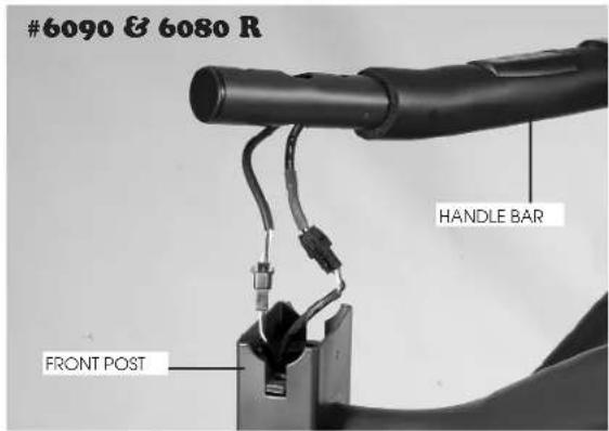
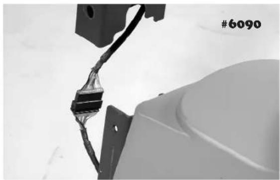
STEP 2.
PLACE HANDLE BARS AT THE TOP OF BOTH SIDES OF FRONT POST. (PLEASE NOTE THE HANDLE BAR WITH SPEED BUTTON IS FOR RIGHT SIDE AND INCLINE BUTTON IS FOR LEFT SIDE). CONNECT 2 CABLES PROVIDED FROM HADLES BAR AND FRONT POST.
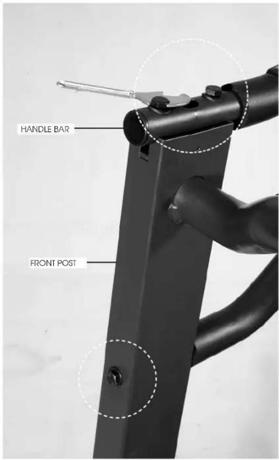
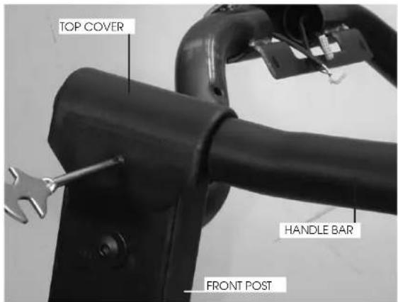
STEP 3:
USE BOLTS & WASHERS (B) TO FIX IT, AND USE BOLT & WASHER (C) TO GO THROUGH FRONT POST AND STAND TO FIX ANOTHER END OF HANDLE BAR ON THE FRONT POST. THEN USE BOLT (E) TO FIX TOP COVER AT THE TOP OF FRONT POST.
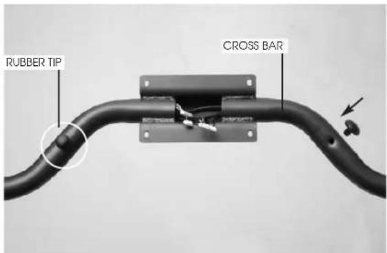
STEP 4:
INSERT TWO RUBBER TIPS INTO THE HOLES ON THE CROSS BAR OF FRONT POST.
STEP 5:
CONNECT ALL THE CABLES PROVIDED FROM COMPUTER AND FRONT POST, THEN USE BOLTS (D) TO FIX COMPUTER TO THE BRACKET ON THE CROSS BAR OF FRONT POST. THEN COVER IT BY COMPUTER BACK COVER.
natural_image
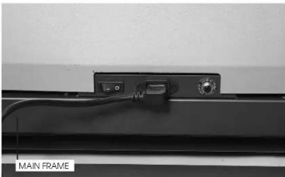
Close-up of a black metal frame with a control knob and cable, labeled 'MAIN FRAME' (no other text or symbols visible)STEP 6:
PLUG IN THE POWER CABLE INTO THE SOCKET AT THE FRONT OF MAIN FRAME.

Before beginning a workout session make sure the safety key is properly placed onto the computer console and the safety clip is securely attached to an article of your clothing.
Always start the treadmill while standing on the side rails but not on the running belt.
Allow the treadmill to reach a speed of at least 1.0 KPH before walking on the running belt.
Before operating read this page first for familiarization of the treadmill computer console and other important features.
WARNING
Temperature generates when motor runs. The longer time it runs, the higher temperature it will generate. Especially when it runs with heavy loading for some time, the temperature will be much higher. Therefore, in order to lengthen the life of motor, please do remember that every time after using, let the treadmill runs without loading in maximum speed for 5 minutes to blow out high temperature.
BASIC INFORMATION
- When safety key is removed:
There is no figure showing on LED.
- When safety key is positioned:
It is in MANUAL model, and all the functions ready. You may also Press FAST or SLOW key to choose P1, P2, P3, P4, P5
When pressing FAST key, the sequence is MN→P1→P2→3→4→P5→MN
When pressing SLOW key, the sequence is MN→P5→P4- P3→P2→P1→MN
HOW TO OPERATE
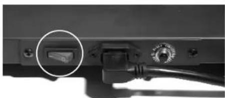
Press the Master Power Switch located at the front of the frame (see page 9 MASTER POWER SWITCH LOCATION) to "ON" position, then insert SAFETY KEY, 0.00 is shown on the big window, 0.8 on the speed window and 0 on the incline window.
STEP 2. BEGIN WORKOUT
First option: Press START button to begin operation. TIME, DISTANCE, & CALORIES will count up. Press MODE button read all the function. The light on the LAP starts flashing and runs in every 25 meters.
Second option: Press MODE button, 0.00 starts flashing.. Press FAST, SLOW button to set desired time. Then press START button to begin operation.
You may press FAST, SLOW button to adjust speed and press UP, DOWN button to adjust incline.
Press the Master Power Switch located at the front of the frame (see page 9 MASTER POWER SWITCH LOCATION) to "ON" position, then insert SAFETY KEY, 0.00 is shown on the big window, 0.8 on the speed window and 0 on the incline window.
STEP 2
Press FAST, SLOW button to choose P1 \~ P5.
Then you may press START button to begin operation followed by STANDARD PRESET time (30 minutes) or follow next step.
STEP 3
Press MODE button, L1 is shown. Then press FAST, SLOW button to choose L1 \~ L3.
Then you may press START button to begin operation followed by STANDARD PRESET time (30 minutes) or follow next step.
STEP 4
Press MODE button, 30:00 is shown and flashing. Then press FAST, SLOW button to increase or decrease time from 10 \~ 99 minutes.
STEP 5
Press START button to begin operation.
You may press FAST, SLOW button to adjust speed and press UP, DOWN button to adjust incline.
Following are detailed speed in different PROGRAM/LEVEL.
TABLE
| SPFFT LEVEL 1 | P1 | P2 | P3 | P4 | P5 |
| Interval 1 | 1.5 KPH | 2.0 KPH | 2.0 KPH | 2.0 KPH | 1.0 KPH |
| Interval 2 | 2.0 KPH | 7.0 KPH | 6.0 KPH | 2.0 KPH | 3.0 KPH |
| Interval 3 | 2.5 KPH | 2.0 KPH | 6.0 KPH | 8.0 KPH | 5.0 KPH |
| Interval 4 | 3.0 KPH | 7.0 KPH | 8.0 KPH | 8.0 KPH | 7.0 KPH |
| Interval 5 | 3.5 KPH | 2.0 KPH | 10.0 KPH | 6.0 KPH | 9.0 KPH |
| Interval 6 | 3.0 KPH | 7.0 KPH | 8.0 KPH | 6.0 KPH | 9.0 KPH |
| Interval 7 | 2.5 KPH | 2.0 KPH | 6.0 KPH | 4.0 KPH | 6.0 KPH |
| Interval 8 | 2.5 KPH | 7.0 KPH | 4.0 KPH | 4.0 KPH | 6.0 KPH |
| Interval 9 | 1.5 KPH | 2.0 KPH | 4.0 KPH | 2.0 KPH | 3.0 KPH |
| Interval 10 | 1.5 KPH | 2.0 KPH | 2.0 KPH | 2.0 KPH | 3.0 KPH |
| SPEED LEVEL 3 | P1 | P2 | P3 | P4 | P5 |
| Interval 1 | 3.5 KPH | 4.0 KPH | 4.0 KPH | 4.0 KPH | 3.0 KPH |
| Interval 2 | 4.0 KPH | 9.0 KPH | 6.0 KPH | 4.0 KPH | 5.0 KPH |
| Interval 3 | 4.5 KPH | 4.0 KPH | 8.0 KPH | 10.0 KPH | 7.0 KPH |
| Interval 4 | 5.0 KPH | 9.0 KPH | 10.0 KPH | 10.0 KPH | 9.0 KPH |
| Interval 5 | 5.5 KPH | 4.0 KPH | 12.0 KPH | 8.0 KPH | 11.0 KPH |
| Interval 6 | 5.0 KPH | 9.0 KPH | 10.0 KPH | 8.0 KPH | 11.0 KPH |
| Interval 7 | 4.5 KPH | 4.0 KPH | 8.0 KPH | 6.0 KPH | 8.0 KPH |
| Interval 8 | 4.5 KPH | 9.0 KPH | 6.0 KPH | 6.0 KPH | 8.0 KPH |
| Interval 9 | 3.5 KPH | 4.0 KPH | 6.0 KPH | 4.0 KPH | 5.0 KPH |
| Interval 10 | 3.5 KPH | 9.0 KPH | 4.0 KPH | 4.0 KPH | 5.0 KPH |
To complete shut off power to the treadmill, turn off master power switch and unplug from outlet.
natural_image
Close-up of a cable connector with a circular button highlighting a component, no visible text or symbols| SPEED LEVEL 2 | P1 | P2 | P3 | P4 | P5 |
| Interval 1 | 2.5 KPH | 3.0 KPH | 3.0 KPH | 3.0 KPH | 2.0 KPH |
| Interval 2 | 3.0 KPH | 8.0 KPH | 5.0 KPH | 3.0 KPH | 4.0 KPH |
| Interval 3 | 3.5 KPH | 3.0 KTH | 7.0 KPH | 9.0 KPH | 6.0 KTH |
| Interval 4 | 4.0 KPH | 8.0 KTH | 9.0 KPH | 9.0 KPH | 8.0 KTH |
| Interval 5 | 4.5 KPH | 3.0 KPH | 11.0 KPH | 7.0 KPH | 10.0 KPH |
| Interval 6 | 4.0 KPH | 8.0 KPH | 9.0 KPH | 7.0 KPH | 10.0 KPH |
| Interval 7 | 2.5 KPH | 3.0 KTH | 7.0 KPH | 5.0 KPH | 7.0 KPH |
| Interval 8 | 3.5 KPH | 8.0 KPH | 5.0 KPH | 5.0 KPH | 7.0 KPH |
| Interval 9 | 2.5 KPH | 3.0 KTH | 5.0 KPH | 3.0 KPH | 4.0 KPH |
| Interval 10 | 2.5 KPH | 3.0 KPH | 3.0 KPH | 3.0 KPH | 4.0 KPH |
IN SUMMARY
• TIME is preset for count down on P1 \~ P5.
- When the SAFETY KEY is removed, motor stops, every program will be reset.
- Please note every program is divided into 10 segments.
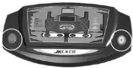
COMPUTER INSTRUCTION
(A) SAFETY KEY
Safety Key is for the operation and emergency stop. Before beginning a workout session ensure safety key is securely attached to an article of your clothing.
(B) EMERGENCY STOP BUTTON
It's on the left side of computer face, you can easily push the button to stop the machine whenever it's necessary.
(C) FAST/SLOW BUTTON
They are for adjusting Speed, choosing Program/Level, and pre-set time.
(D) STOP/START BUTTON
It's to start or stop the machine
(E) MODE BUTTON

natural_image
Front view of a JKXCR gaming controller device with control panels and buttons (no readable text or symbols)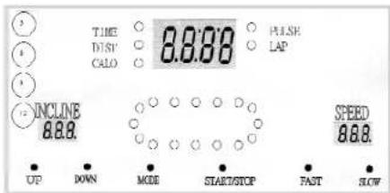
Before machine starts, it's for entering function, and after machine starts, it's for switching functions.
(F) UP/DOWN BUTTON
They are for adjusting incline from 0 \~ 10%.
(G) SPEED BAR
There are 4 speeds, 3, 6, 9, & 12 KPH shown on the left side of computer. Whenever the machine is running, you may press one of these 4 buttons, the speed will be automatically increased without necessity of pressing FAST, SHOW button.
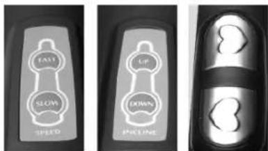
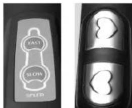
(H) HANDLE BAR SPEED BUTTON
Adjust speed from this button any time you want.
(I) HANDLE BAR INCLINE BUTTON
Adjust incline from this button any time you want.
(J) PULSE SENSOR PLATE
Both hands must hold on two plates at the same time to read your heart beat on the computer.
(H) (I) (J)
FUNCTIONS DISPLAY
TIME : Count up; Accumulates total working time from zero to 99:99 Count down; Counts the preset working time backwards to zero to stop running.
DISTANCE : Count up; Accumulates total working distance from zero to 99.99KM or MILES.
CALORIES : Count up; Accumulates calories consumption during exercise from zero to 99.99 KCAL. (0.01 means 1 CAL.)
PULSE : It shows your heart beat when holding sensor plates on two handle bars.
LAP : There are 16 lights on the 400 meters lap.
SPEED : Display the desired running belt speed. The speed can be adjusted from Min. 0.5MPH/0.8KPH to 10MPH/16KPH by 0.1 increments by pushing FAST or SLOW buttons.
INCLINE : Display the desired gradient percentage from 0 \~ 10%.
Before beginning a workout session make sure the safety key is properly placed onto the computer console and the safety clip is securely attached to an article of your clothing.
Always start the treadmill while standing on the side rails but not on the running belt.
Allow the treadmill to reach a speed of at least 1.0 KPH before walking on the running belt.
Before operating read this page first for familiarization of the treadmill computer console and other important features.
WARNING
Temperature generates when motor runs. The longer time it runs, the higher temperature it will generate. Especially when it runs with heavy loading for some time, the temperature will be much higher. Therefore, in order to lengthen the life of motor, please do remember that every time after using, let the treadmill runs without loading in maximum speed for 5 minutes to blow out high temperature.
BASIC INFORMATION
- When safety key is removed:
There is no figure showing on LED.
- When safety key is positioned:
It is in MANUAL model, and all the functions ready. You may also Press FAST or SLOW key to choose P1, P2, P3
When pressing FAST key, the sequence is MN→P1→P2→3→MN
When pressing SLOW key, the sequence is MN→P3→P2→P1→MN
HOW TO OPERATE
Press the Master Power Switch located at the front of the frame (see page 9 MASTER POWER SWITCH LOCATION) to "ON" position, then insert SAFETY KEY, 0.00 is shown on the big window.
STEP 2.BEGIN WORKOUT
First option: Press START button to begin operation. TIME, DISTANCE, & CALORIES will count up. Press MODE button read all the function. The light on the LAP starts flashing and runs in every 25 meters.
Second option: Press MODE button, 0.00 starts flashing. Press FAST, SLOW button to set desired time. Then press START button to begin operation.
You may press FAST, SLOW button to adjust speed.
OPERATION IN PROGRAM P1 \~ P3
STEP 1. POWER UP
Press the Master Power Switch located at the front of the frame (see page 9 MASTER POWER
SWITCH LOCATION) to "ON" position, then insert SAFETY KEY, 0.00 is shown on the big window.
STEP 2
Press FAST, SLOW button to choose P1 \~ P3.
Then you may press START button to begin operation followed by STANDARD PRESET time (30 minutes) or follow next step.
STEP 3
Press MODE button, 30:00 is shown and flashing. Then press FAST, SLOW button to increase or decrease time from 10 \~ 99 minutes.
STEP 4
Press START button to begin operation.
You may press FAST, SLOW button to adjust speed
Following are detailed speed in different PROGRAM.
TABLE
| SPEED | P1 | P2 | P3 |
| Interval 1 | 1.5 KPH | 2.0 KPH | 2.0 KPH |
| Interval 2 | 2.0 KPH | 7.0 KPH | 4.0 KPH |
| Interval 3 | 2.5 KPH | 2.0 KPH | 6.0 KPH |
| Interval 4 | 3.0 KPH | 7.0 KPH | 8.0 KPII |
| Interval 5 | 3.5 KPH | 2.0 KPH | 10.0 KPH |
| Interval 6 | 3.0 KPH | 7.0 KPH | 8.0 KPH |
| Interval 7 | 2.5 KPH | 2.0 KPH | 6.0 KPII |
| Interval 8 | 2.5 KPH | 7.0 KPH | 4.0 KPH |
| Interval 9 | 1.5 KPH | 2.0 KPH | 4.0 KPH |
| Interval 10 | 1.5 KPH | 2.0 KPH | 2.0 KPH |
IN SUMMARY
- TIME is preset for count down on P1 \~ P3.
- When the SAFETY KEY is removed, motor stops, every program will be reset.
- Please note every program is divided into 10 segments.
COMPUTER INSTRUCTION
(A) SAFETY KEY
Safety Key is for the operation and emergency stop. Before beginning a workout session ensure safety key is securely attached to an article of your clothing.
(B) EMERGENCY STOP BUTTON
It's on the left side of computer face, you can easily push the button to stop the machine whenever it's necessary.
(C) FAST/SLOW BUTTON
They are for adjusting Speed, choosing Program, and preset time.
(D) STOP/START BUTTON
It's to start or stop the machine
(E) MODE BUTTON
Before machine starts, it's for entering function, and after machine starts, it's for switching functions.
natural_image
Front view of a JMC CR game controller display showing steering wheel, dashboard, and control buttons (no readable text or symbols)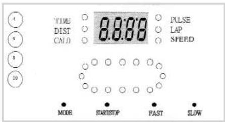
(F) SPEED BAR
There are 4 speeds, 4, 6, 8, & 10 KPH shown on the left side of computer. Whenever the machine is running, you may press one of these 4 buttons, the speed will be automatically increased without necessity of pressing FAST, SHOW button.
(G) TOGGLE SWITCH
It's the switch on the right side of computer face. Push upper end to make the frame higher, push lower end to make the frame lower. The maximum is around 10%. The gradient percentage is not
readable from computer.
(H) HANDLE BAR SPEED BUTTON
Adjust speed from this button any time you want.
(I) PULSE SENSOR PLATE
Both hands must hold on two plates at the same time to read your heart beat on the computer.
(H)(1)
FUNCTIONS DISPLAY
TIME : Count up; Accumulates total working time from zero to 99:99 Count down; Counts the preset working time backwards to zero to stop running.
DISTANCE : Count up; Accumulates total working distance from zero to 99.99KM or MILES.
CALORIES : Count up; Accumulates calories consumption during exercise from zero to 99.99 KCAL. (0.01 means 1 CAL.)
PULSE : It shows your heart beat when holding sensor plates on two handle bars.
LAP : There are 16 lights on the 400 meters lap.
SPEED : Display the desired running belt speed. The speed can be adjusted from Min. 0.5MPH / 0.8KPH to 7.5MPH / 12KPH by 0.1 increments by pushing FAST or SLOW buttons.
ERROR MESSAGE & TROUBLE SHOOTING
E1 (Error 1):
When the machine starts but computer could not read the signal from sensor for 6 seconds, E1 will be shown on the computer.
E6 (Error 6):
When the incline motor starts but computer could not read VR figure from incline motor for 6 seconds, E6 will be shown on the computer.
If any above troubles happen, please consult the distributor.
SMELL
If any smell comes out from motor, please firstly spray out some silicone on the running board (Please refer to page 17 RUNNING BOARD MAINTENANCE), and see if the situation improves. Then consult the distributor for necessary help.
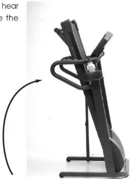
HOW TO FOLD UP FOR STORAGE
Lift the rear end of the frame to the computer till you hear a "CLICK" sound then push and pull it to make sure the frame is fixed.
natural_image
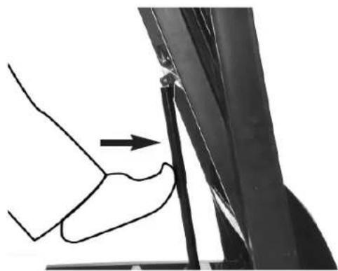
Black stationary exercise machine with curved arm and side-mounted legs, shown in motion (no text or symbols visible)HOW TO FOLD DOWN FOR EXERCISE
There is a plate fixed onto crossbar at the bottom of main frame. It is to safety control air-oil shock. To fold down the frame, please hold your hand on the frame and use your foot to push at the center of air-oil shock (as photo shown) then lean down the frame into the ground.
natural_image
Diagram of a hand pressing down on a vertical pipe or pipe junction, with an arrow indicating force direction (no text or symbols present)HOW TO START THE MACHINE
STEP 1:
TURN THE MASTER POWER SWITCH ON
STEP 2:
PLACE SAFETY KEY ON THE COMPUTER
STEP 3:
NOW YOU CAN PUSH THE START BUTTON ON THE COMPUTER TO START EXERCISING.
HOW TO MOVE
WHEN THE FRAME IS NOT FOLDING UP:
This machine is equipped with 4 rollers underneath the front of main frame and two transport wheel on the rear, you may just push it forward or backward. But before moving, please make sure: 1. Power cord is unplugged from the electrical outlet.
- Two balancers are screwed into the bottom of main frame and do not touch the ground.
WHEN THE FRAME IS FOLDING UP:
After frame is folding up, unplug the power cord, screw in the balancers, then tilt the frame for moving.
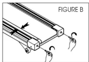
ALIGNING THE RUNNING BELT
Ensure the running belt is centered on your treadmill at all times. Running style and
Non-level surface are two instances which may cause the belt to drift off center.
Minor adjustments to the two bolts at the front of the treadmill are necessary when the belt has drifted off center. See fig. A & B.
-
Press the Master Power Switch (located in the front of the treadmill) to ON position and ensure Safety Key is properly placed onto the computer console, press the START button to begin running belt, then and increase the treadmill's speed to 3 mph.
-
Stand at the front of the treadmill and to determine which side the belt is drifting.
-
If the belt drifts to the left, turn the right adjustment bolt one-quarter of a turn Clockwise and the right adjustment bolt one-quarter counter clockwise. See Fig. A.
-
If the belt drifts to the right, turn the right adjustment bolt one-quarter of a turn Clockwise and turn the left adjustment bolt one-quarter turn counter-clockwise. See Fig. B.
-
Observe the tracking of the belt for about two minutes. Repeat Steps 3, 4, and 5 as needed.

ADJUSTING THE RUNNING BELT TENSION
Adjust belt tension if it begins to slip on the rollers. This is important as it increases
Longevity of the treadmill's components.
When adjusting belt tension, keep the belt as loose as possible!!!
- Press the Master Power Switch (located at the front of the treadmill) to ON POSITION and ensure safety key is properly placed onto the computer console. Press the START button to begin running belt, then adjust the treadmill's speed To 3 mph.
- Turn both adjustment screws an equal amount, approximately one-quarter turn Clockwise.
- Slow the belt by holding onto the handrails and applying more weights as you Walk, (as if you were walking downhill). When breaking heavily the belt may Slip.
- If the belt slips, adjust one-quarter turn clockwise and repeat Step 3 as necessary.
ALWAYS BE CAREFUL NOT TO OVERTIGHTEN THE RUNNING BELT.
CLEANING AND INSPECTING THE RUNNING BELT
Turn off power and unplug from electrical outlet.
Carefully position the treadmill on its side.
Use a damp cloth to wipe off the inside of the running belt. Carefully rotate the running belt by hand to clean the entire inside face. Return treadmill to its upright
Position.
If running belt edges are frayed, check the running belt adjustment (see page 12).
If seams are splitting, call your retailer or nearest authorized service center.
CLEANING
Before proceeding ensure that the treadmill's power if off and that is unplugged from the electrical outlet.
To remove dust use a small vacuum nozzle to carefully vacuum around all visible
Components.
To remove film or dirt use a slightly damp rag with a mild cleaning agent sprayed onto the rag only.
Be careful not to immerse any treadmill component with any liquids.
INSPECT FASTENERS AND WIRING
Check that all fasteners are properly tightened and all wiring is securely in place. To avoid damaging fasteners, do not over tighten.
STORAGE
Store your treadmill in a clean and dry environment. Ensure the master power switch Is off and is unplugged from the electrical wall outlet.
RUNNING BOARD MAINTENANCE
CONGRATULATE THAT YOU OWN THIS MOTORIZED TREADMILL!
PLEASE FOLLOW THE BELOW INSTRUCTIONS TO MAINTAIN THE RUNNING BOARD FOR A LONG-TERM, FUNCTIONAL OPERATION:
First of all, we strongly suggest you check with your doctor before you start your walking program. Of course, if your have arthritis, anemia, low back pain, uncontrolled diabetes, or serious diseases of the lungs, kidneys, liver, or heart, you should see a doctor regularly anyway.
To work out efficiently, we suggest using your heart rate as a guide. Everyone has what is called a "Maximum Heart Rate". Your maximum heart rate is the number of beats your heart makes per minute when you are running as far, as fast, and as long as possible. Although it varies from person to person, your maximum heart rate is roughly 220 minus your age. That is, if you are 20 years old, your maximum heart rate is about 200; If you are 40, it is about 180.
However, it could be dangerous if exercise at your maximum heart rate. And physiologists have figured out a safe heart range for most people. They call it "Target Heart Rate". This Target Heart Rate, as it is called in cardiovascular exercise programs, is considered about 60 to 85 percent of your Maximum Heart Rate. This is your optimum level for exercise. Exercise at least 3 times a week, keep your heart beat within Target Heart Rate for minimum 20 minutes per time will get the most advantage of your workout.
For example:
If you are 30 years old, your Maximum Heart Rate is 220 - 30 = 190.
Your Target Heart Rate is about 114 \~ 160.
$$ 190 \times 60 \% = 114 $$
$$ 190 \times 85\% = 161.5 $$
As the computer of this model equips no pulse function, suggest you may wear a transmitter and watch to dictate your heart beat during workout.
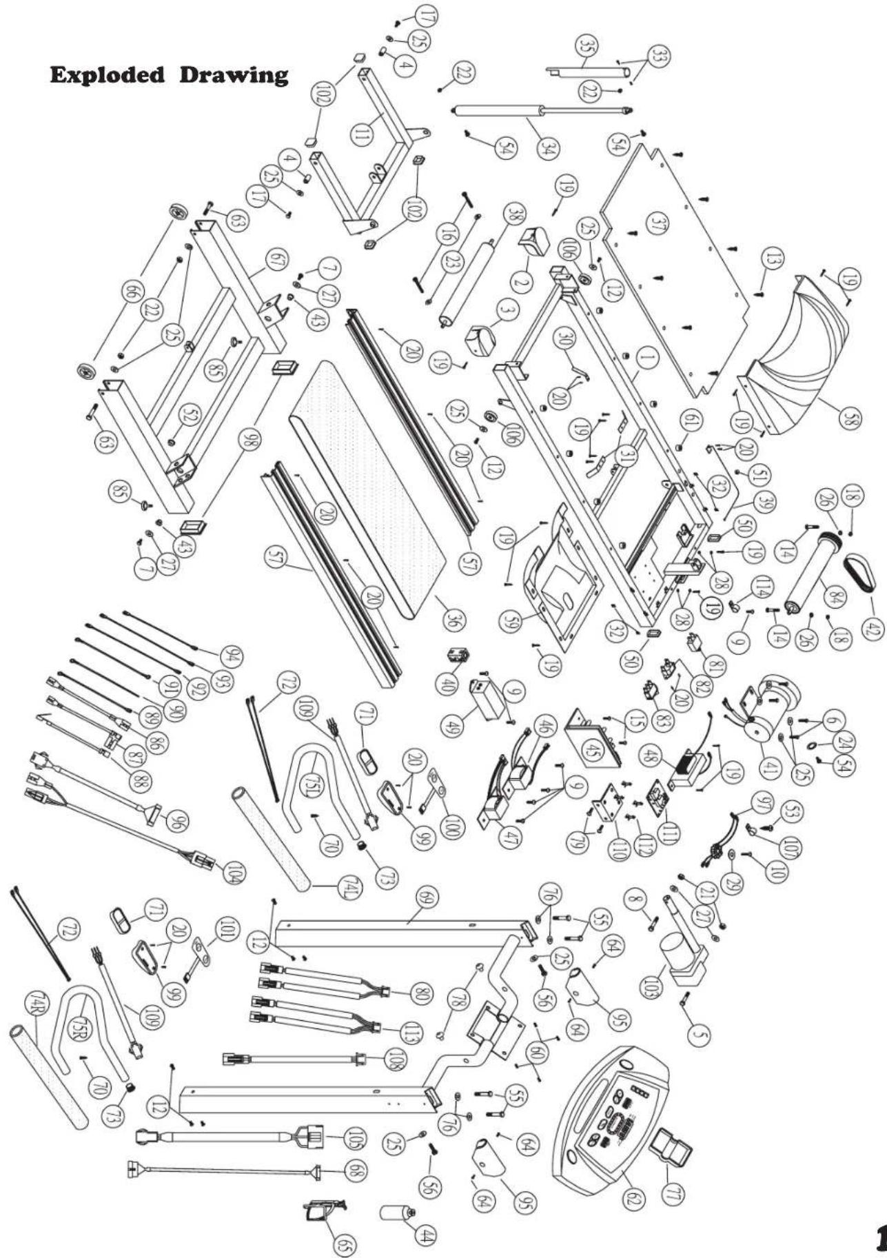
PARTSLIST (B.O.M.)
| NO | DESCRIPTION | Q.Y | B.O.M | 6080 | 6090 |
| 1 | MAIN FRAME | 1 GB20-609000101 | ** | ||
| 2 | REAR CAP [L] | 1 EA0011-003129L | ** | ||
| 3 | REAR CAP [R] | 1 EA0011-003129R | ** | ||
| 4 | SLEEVE TUBE 11.2x26.5x1.5t | 2 BB0325-C02650 ** | |||
| 5 | BOLT M10*40 | 1 CA1004-00350B ** | |||
| 6 | BOLT M8*15 4 CA1003-00050B ** | ||||
| 7 | BOLT M10*30 | 2 CA1003-00082B ** | |||
| 8 | BOLT M10*75 | 1 CA1004-00430B ** | |||
| 9 | BOLT M4*6 | 7 CA1006-101500 ** | |||
| 10 | BOLT M5*30 1 CA1006-10330B ** | ||||
| 11 | FRONT FRAME | 1 GB20-608000500 | ** | ||
| 12 | BOLT M8*15 8 CA1013-10290B ** | ||||
| 13 | SCREW 1/4*38 | 8 CA1016-610238B | ** | ||
| 14 | BOLT M6*75 2 CA1015-100675B ** | ||||
| 15 | BOLT M5*12 2 CA1006-10290B ** | ||||
| 16 | BOLT M6*65 2 CA1012-20500B ** | ||||
| 17 | BOLT M8*35 2 CA1003-00063B ** | ||||
| 18 | NUT M6 | 2 CA2004-00040B ** | |||
| 19 | SCREW 5/32*16 | 23 CA1016-00195P ** | |||
| 20 | SCREW M3*10 | 16 CA1016-300100 ** | |||
| 21 | NUT M10 | 2 CA2004-00075B ** | |||
| 22 | NUT M8 | 4 CA2004-00060B ** | |||
| 23 | WASHER M6*13 | 2 CA3002-00075B ** | |||
| 24 | WASHER M8*16 | 1 CA3002-00095B ** | |||
| 25 | WASHER M8*19 | 12 CA3002-00097B ** | |||
| 26 | SPRING WASHER 1/4 | 2 CA3003-00040B ** | |||
| 27 | WASHER M10*22 | 4 CA3005-00080B ** | |||
| 28 | BS BS WASHER M4 | 9 CA3005-000930 ** | |||
| 29 | WASHER M8*35 | 1 CA3002-001000B ** | |||
| 30 | SPRING | 1 CB4001-1610300B ** | |||
| 31 | CENTER BAR | 2 CB4001-210720 ** | |||
| 32 | FIXING PLATE | 4 CB4001-220165 ** | |||
| 33 | BOLT M4*12 2 CA1006-001600B ** | ||||
| 34 | AIR SHOCK 1 DA0001-101020 * | ||||
| 35 | SAFTY TUBE | 1 GA10-608000610 | ** | ||
| 36 | RUNNING BELT | 1 DA0002-1003310B ** | |||
| 37 | RUNNING DECK | 1 DA0004-001170N | ** | ||
| 38 | REAR ROLLER | 1 DA0006-881020B | ** | ||
| 39 | SENSOR | 1 DA0007-200670 ** | |||
| 40 | CLIP | 1 DA0010-001500 ** | |||
| 41 | MOTOR | 1 DA0010-11100230 * | |||
| MOTOR | 1 DA0010-1130230B | * | |||
| 42 | POLY-BELT | 1 DA0010-1201400 | ** | ||
| 43 | SLEEVE | 2 CB4001-400015 ** | |||
| 44 | KETTLE | 1 EA0011-003205 | ** | ||
| 45 | CONTROL BOX | 1 DA0012-220V060 | ** | ||
| 46 | TRANSFORMER (T2) | 1 DA0014-220V030 | ** | ||
| 47 | TRANSFORMER (T4) | 1 DA0014-220V040 | ** | ||
| 48 | CHOKE | 1 DA0014-220VC03 | ** | ||
NO DESCRIPTION Q Y B.O.M 6080 6090
| 49 FILTER (4A) 1 DA0015-000020 * | ||
| FILTER (7A) 1 DA0015-000010 * | ||
| 50 CAP 25.4*50.8 2 EA0001-100300 ** | ||
| 51 FIXING CLIP 1 EA0001-600700 ** | ||
| 52 FIXING CLIP OSB-26 1 EA0001-6100060 ** | ||
| 53 SCREW M5*12 1 CA1016-50512BS ** | ||
| 54 BOLT M8*25 3 CA1003-00061B ** | ||
| 55 BOLT M8*55 4 CA1004-00225B ** | ||
| 56 BOLT M8*100 | 2 CA1003-00075B ** | |
| 57 SIDE COVER(L) | 2 HASM-609005500 * | |
| 58 COVER | 1 HASM-608006000 ** | |
| 59 BOTTOM COVER | 1 EA0011-1205610B ** | |
| 60 BOLT M6*25 4 CA1006-10420B ** | ||
| 61 RUBBER TIP 8 EA0001-70190705 ** | ||
| 62 COMPUTER | 1 HA01-608005400 * | |
| COMPUTER | 1 HA01-609005400 * | |
| 63 BOLT M8*50 2 CA1004-00220B ** | ||
| 64 BOLT M4*10 | 4 CA1006-10160B ** | |
| 65 KETTLE FRAME | 1 EA0011-0310000 ** | |
| 66 WHEEL | 2 EA0008-000560 ** | |
| 67 BOTTOM STAND | 1 GB20-608000200 ** | |
| 68 CABLE 1600mm | 1 DA0010-15007P60 * | |
| CABLE 1600mm | 1 DA0010-15012P65 ^ | |
| 69 SIDE FRAME | 1 GB20-608000300 ** | |
| 70 CSREW 5/32*25 | 2 CA1016-001950B ** | |
| 71 HAND PULSE | 2 DA0007-720020 ** | |
| 72 CABLE 400mm 2 DA0010-150610 ** | ||
| 73 CAP | 2 EA0001-200700 ** | |
| 74L HAND GRIP(L) | 1 EA1415-078000FA * | |
| 74R HAND GRIP(R) 2 EA1415-078000FA1* | ||
| 75L HAND RAIL(L) 1 GA10-508000610 * | ||
| 75R HAND RAIL(R) | 2 GA10-608000410 ** | |
| 76 CURVED WASHER M8 | 4 CA3002-10090B ** | |
| 77 CAP | 1 | |
| 78 RUBBER TIP 2 EA0011-7200140 ** | ||
| 79 BOLT 1/8*5/16 | 2 CA1005-001500 * | |
| 80 CABLE (2+2C) | 1 DA0010-153A550 ** | |
| 81 BREAKER (7A) 1 DA0010-130032 * | ||
| BREAKER (10A) | 1 DA0010-130033 * | |
| 82 SOCKET | 1 DA0010-160100 ** | |
| 83 SWITCH | 1 EA0011-003870 ** | |
| 84 FRONT ROLL | 1 DA0006-400350B ** | |
| 85 ADJUSTING TIP | 2 EA0001-001220 ** | |
| 86 CABLE (BLUE) 130mm | 1 DA0010-1500273 ** | |
| 87 CABLE (BROWN) 100mm 1 DA0010-155C100N** | ||
| 88 CABLE (BROWN) 170mm 1 DA0010-155D170N** | ||
| 89 GROUND CABLE | 1 DA0010-1500381 ** | |
| 90 GROUND CABLE | 1 DA0010-1500381 ** | |
| 91 GROUND CABLE | 1 DA0010-1500381 ** | |
| NO | DESCRIPTION | Q Y | B.O.M | 6080 | 6090 |
92 CABLE (BLUE) 350mm 1 DA0010-1500310 **
93 CABLE (BROWN) 200mm 1 DA0010-150030**
94 CABLE (BLUE) 200mm 1 DA0010-1500314 **
95 CAP 2 EA0001-300740 **
96 CABLE 700mm 1 DA0010-15007P70 *
CABLE 750mm 1 DA0010-15012P60 *
97 MAGNET 1 HASM-910006000 **
98 CAP 40*80 2 EA0001-100130 **
| 99 SWITCH PLATE 2 EA0011-3500000 | ** |
100 SWITCH(SPEED) 1 DA0017-1000100 **
101 SWITCH(INCLINE) 1 DA0017-1100100
102 CAP 25.4*50.8 4 EA0001-100500 **
103 INCLINE MOTOR 1 DA0010-60800220 *
INCLINE MOTOR 1 DA0010-60900220
104 CABLE 650mm 1 DA0010-14A00650 *
105 CABLE 1600mm 1 DA0010-14B01600*
106 WHEEL 2 EA0008-3000900 **
107 FIXING CLIP (UC-0.5) 1 EA0011-000794B **
108 CABLE 550mm 1 DA0010-151C0550 *
109 CABLE 250mm 2 DA0010-151E0250**
110 L L PLATE 1 BA0030-003250 *
111 INCLINE CONTROL 1 DA0013-0500000 *
112 PC ISOLATOR 4 EA0011-0006600
113 CABLE (3+3C) 1 DA0010-156A0550 *
114 FIXING CLIP (UC-1.5) 1 EA0011-000794B **
Factory:
JIH KAO ENTERPRISE CO., LTD