
SGS-CH01 - Dashboard camera ALPINE - Free user manual and instructions
Find the device manual for free SGS-CH01 ALPINE in PDF.


| Product Type | Camera Interface Module with Active Guidelines |
| Brand | Alpine |
| Model | SGS-CH01 |
| Compatible Vehicles | Jeep Wrangler JK (2007-2010 static guidelines, 2011-2018 active and static) |
| Input Voltage | 12V DC (negative ground) |
| Normal Power Consumption | 4.32W (0.36A @ 12V) |
| Standby Current Draw | <20mA |
| Operating Temperature | -40°C to +85°C |
| Dimensions (W x H x D) | 10.5 x 8.5 x 2.2 cm |
| Reverse Trigger Threshold | >5V |
| Video Input (Front/Rear Camera) | 0.5 - 2Vpp, 75 ohm impedance |
| Guidelines Support | Static (2007-2010) and Active (2011-2018) |
| Connectors | Jeep T-Harness (male/female), Camera Harness, Main Harness |
| Accessories Included | Interface Module, Camera Harness, Main Harness, Cable Ties (x2), Velcro (x2) |
| Safety Warnings | Disconnect battery before installation; do not disassemble; use only with 12V negative ground; avoid installing near airbags |
| Installation Requirement | Requires specialized skills; recommended installation by Alpine authorized dealer |
| Dip Switch Configuration (2007-2010) | Switch 1 down (On), switches 2,3,4 up (Off) |
| Dip Switch Configuration (2011-2018) | All switches up (Off) |
| LED Indicators | Top LED flashes when CAN data read; bottom LED solid when CAN active |
| OSD Interface | Menu button to toggle guidelines on/off |
Frequently Asked Questions - SGS-CH01 ALPINE
User questions about SGS-CH01 ALPINE
0 question about this device. Answer the ones you know or ask your own.
Ask a new question about this device
Download the instructions for your Dashboard camera in PDF format for free! Find your manual SGS-CH01 - ALPINE and take your electronic device back in hand. On this page are published all the documents necessary for the use of your device. SGS-CH01 by ALPINE.
USER MANUAL SGS-CH01 ALPINE
Factory Radio Camera Interface with Active Guideline system Installation Manual
● Model: Wrangler
● Model Year: 2011-2018
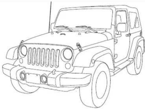
Model Year Active Guidelines Static Guidelines
| Jeep | Wrangler (JK) 2007-2010 | ✗ | √ |
| Wrangler (JK) 2011-2018 | √ | √ |
DISCLAIMER: The active guideline feature of this product is calibrated for use with JEEP WRANGLER model years 2011-2018. The accuracy of the active guideline system cannot be guaranteed if used in conjunction with other vehicles or those which contain non-factory parts which may affect the turning radius of the vehicle.
* The specified vehicles have been tested and have met compatibility specs at the time of testing. Compatibility is not guaranteed if the manufacturer has made production changes to the listed vehicles above.
⚠ Warning: Before you begin wiring, remove the ground wire from the negative terminal of the battery. Failing to do so can lead to electric shock, injury or damage to equipment.
Introduction
- Congratulations on purchasing the SGS-CH01. This installation manual is designed to take you through the installation of SGS-CH01. Please familiarize yourself with the owners manual and if you still have additional questions please call 1-800-TECH-101.
Note
- Design and specifications are subject to change without notice for improvement.
To Ensure Safe Use, Always Follow These Precautions
● The installation of this product requires specialized skills and experience. We recommend that you have the product installed by an Alpine authorized dealer.
- Before you use this product, be sure to carefully read this installation manual and the separate user's manual so that you can use the product correctly. Alpine Electronics bears no responsibility for problems that arise as a result of failure to follow the instructions in the manuals.
- This manual includes a number of symbols that are intended to help you use the product safely, to prevent harm to you and others, and to protect against damage to property. These symbols and their meanings are listed below. Make sure you fully understand these symbols before you begin reading the main text.
Explanations of Injury and Damage That May Result from Incorrect Use
 Warning Warning | Ignoring the content marked by this indication and using the product incorrectly is expected to lead to death or serious injury. |
 Caution Caution | Ignoring the content marked by this indication and using the product incorrectly is only expected to lead to injury or property damage. |
Types of Precautions
 Forbidden Forbidden | Indicates actions that are forbidden (must not be performed) |
 Forbidden Forbidden | Indicates that disassembly is forbidden. |
 Mandatory Mandatory | Indicates actions that are mandatory (must be performed) |
 | Marks content that should receive your full attention. |

Warning
Do not disassemble or modify the product. Doing so could lead to an accident, fire, or electric shock.

Forbidden
Store screws and other small objects where small children cannot reach them. If one of these small objects is swallowed, consult with a doctor immediately.

When replacing fuses, be sure to use fuses with the specified current rating. Failing to do so could lead to an accident or fire.

Forbidden

Mandatory
Only connect the product to a 12 VDC negative ground car. Failing to do so could lead to an accident or fire.

Mandatory
Before you begin wiring, remove the ground wire from the negative terminal of the battery. Failing to do so could lead to electric shock or injury.

Do not cut the insulation on a cord and take power from another device. Doing so could lead to fire or electric shock.

Forbidden
Do not install the product in a location where it will obstruct the driver's forward view; interfere with the operation of the steering wheel, gearshift, or the like; or pose a threat to passengers. Doing so could lead to an accident or injury.

Forbidden
Jeep/Chrysler/Dodge
SGS-CH01 ● 2/11
When making a hole in the vehicle body, be careful to avoid damaging pipes, the fuel tank, electrical wiring, and the like. This kind of damage could lead to an accident or fire.

When installing and grounding the product, do not use any of the bolts or nuts of the steering wheel, brakes, fuel tank, or the like. Doing so could make the brakes stop working or lead to fire.

Forbidden
Do not install the product near the passenger-side airbag. Doing so could interfere with the operation of the airbag and lead to an accident or injury.

Forbidden
Bundle cords so that they don't interfere with driving. Wrapping cords around the steering wheel, gearshift, brake pedal, or the like, could lead to an accident or damage equipment.


Caution
Connect the product properly according to the instructions. Failing to do so could lead to fire or an accident.

Forbidden
Do not sandwich cords between the seat railing or allow them to touch protrusions. Resulting breaks or shorts could lead to electric shock or fire.

Do not block vents or heat sinks. Doing so could lead to fire or damage equipment.

Use the accessories according to the instructions, and attach them securely. Failing to do so could lead to an accident or damage equipment.

Forbidden
Do not install the product where it may be exposed to water or in a place with high levels of humidity or dust. Doing so could lead to fire or damage equipment.

Forbidden
The installation and wiring of this product requires specialized skills and experience. Have the product installed by an Alpine authorized dealer.

Tools Possibly Required (This Will Vary Depending On The Vehicle)
| Panel Removing Tool Sockets | Phillips Screwdriver | |
 |  |  |
| Wire Cutters Extension Ratchet | ||
 |  |  |
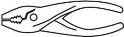
| Crimpers Pliers Torx Screwdriver | ||
 |  |  |
Accessory List
Installation Kit Parts
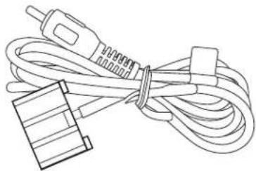
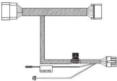
| Interface Module Camera Harness Main Harness | ||
 |  |  |
| Cable Ties x 2 Velcro x 2 | ||
 |  | |
Warning: Before you begin wiring, remove the ground wire from the negative terminal of the battery. Failing to do so can lead to electric shock, injury or damage to equipment.
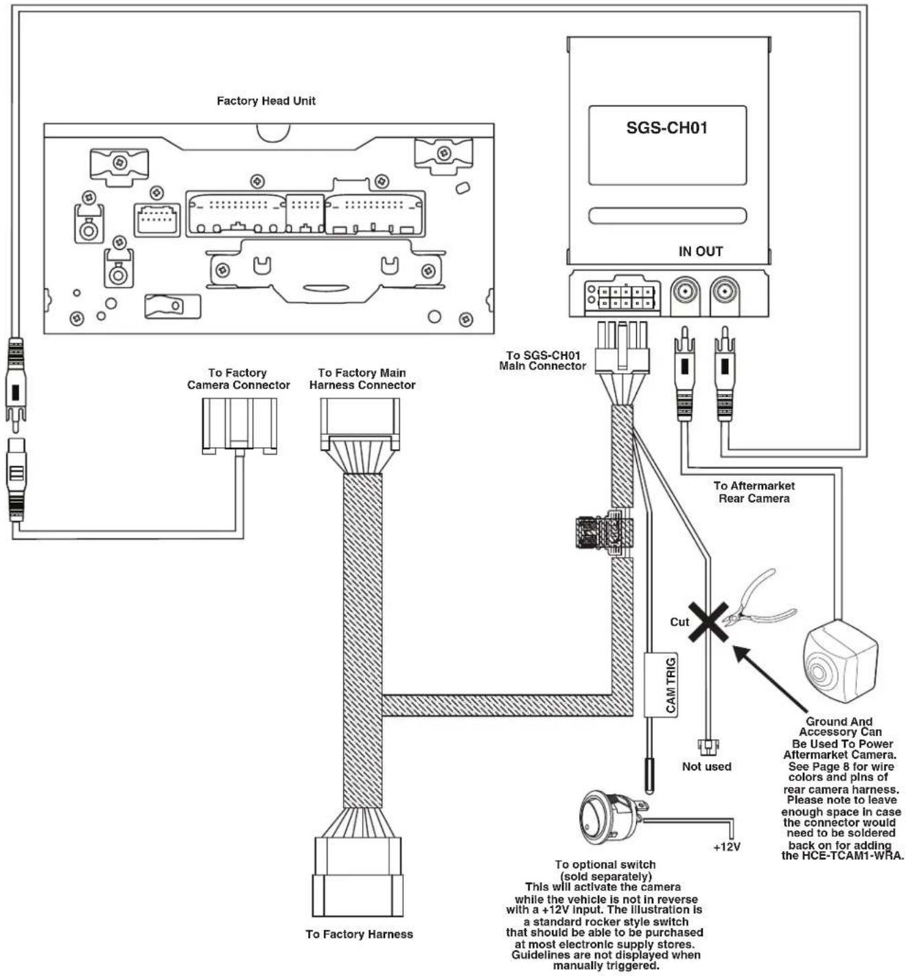
SGS-CH01 Wiring Diagram: OEM Head Unit With HCE-TCAM1-WRA

SGS-CH01 Wiring Diagram: OEM Head Unit With Aftermarket Camera
SGS-CH01 Wiring Diagram: OEM Head Unit With KCX-C2600B (Sold Separately)
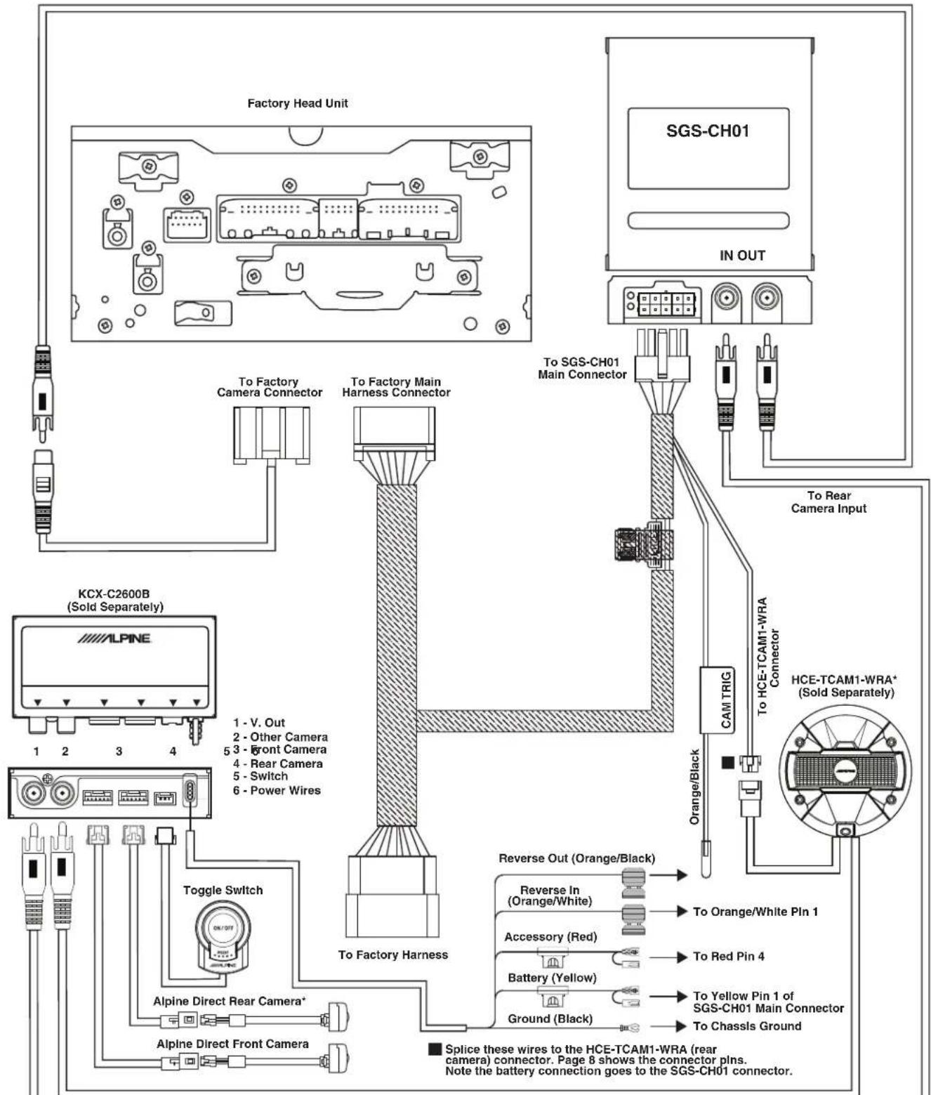
*Only one rear camera can be used for a total of 2 cameras (one front and one rear). The direct input will always take precedence over the RCA input. The HCE-TCAM1-WRA must be plugged into the RCA input for “Other Camera”. A direct camera to RCA adapter will not work.
SGS-CH01 Wiring Diagram: Alpine Head Unit With HCE-TCAM1-WRA

**NOTE: Make sure to turn the Guidelines and cones off in the Alpine head unit. Refer to the owners manual of the product. Owners manuals can be found at www.alpine-usa.com/support
Wire Harness Pin Outs
Jeep T-Harness Male

SGS-CH01 Connector

| 1 | 2 | 3 | 4 | 5 |
| 6 | 7 | 8 | 9 | 10 |
| Pin 1 | Battery | Pin 6 | Ground |
| Pin 2 | CAN-IN + | Pin 7 | CAN-IN - |
| Pin 3 | CAN-OUT + | Pin 8 | CAN-OUT - |
| Pin 4 | ACC OUT (12V, 3A) | Pin 9 | Foot brake Output (12V, 3A) |
| Pin 5 | Camera Trigger | Pin 10 | Reverse Light Output (12V, 3A) |
Jeep T-Harness Female
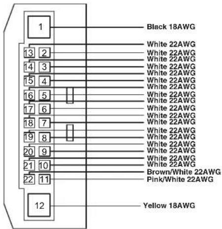

Camera Harness

Rear Camera

Dip Switch Settings

2007-2010 Jeep Wrangler JK- Remove power by unplugging the main connector to the SGS-CH01. To enable static guidelines dip switch 1 must be DOWN (On position) and dip switches 2, 3, and 4 must be UP (Off position).
2011-2018 Jeep Wrangler JK- All dip switches must remain UP (Off position). If any dip switches are in the wrong position the interface will not function properly.
Product Usage (Active Guidelines)
1 Engage vehicle in reverse gear.
2 Reverse camera will turn on automatically.
3 The Active Guidelines will appear only after the steering wheel is turned and move according to the steering wheel position.
4 After shifting out of reverse position the screen on the head unit will show it's normal information.

Using On-Screen Display (OSD) Interface To Turn Off Guidelines

1 Engage vehicle in reverse gear.
2 The 3 buttons on the side of the module are used to make selections with the On-Screen Display. Press the "Menu" button to bring up the OSD illustrated below.
3 Press the "Menu" button again to navigate down to the "Guide-CNTRL" option. After scrolling through the final selection the OSD will close.
5 Toggle the function on or off using the "Up" and "Down" keys. Select the preference accordingly.
6 Press the "Menu" button to scroll through the rest of the options until the OSD menu disappears from the screen. Disengage the reverse gear, then put the vehicle back in reverse to make sure the changes are working.

**NOTE: Make sure to set the Guidelines to be ON or OFF before putting the vehicle dash back together as this option can only be changed from the OSD menu.
If any of the other parameters are selected and changed it will not change the parameter in the system.
LED Functions

1 The top LED will flash when CAN data is being read by the SGS-CH01
2 The bottom LED will remain on solid when vehicle CAN data is active. It will turn off when the vehicle CAN data turns off.
Specifications
| Spec Parameter | |
| Front Cam Video, Reverse Cam Video 0.5 - 2Vpp with 75 ohm impedance | |
| Reverse Control Wire >5V will force into camera mode | |
| Normal Power Consumption 4.32W (0.36A @ 12V) | |
| Standby Current Draw <20mA | |
| Reverse Trigger Threshold >5V Trigger | |
| Working Temperature -40C to +85C | |
| Dimensions 10.5 x 8.5 x 2.2cm | |
Troubleshooting
| Symptom Possible Cause Remedy | |||
| 1 | Headunit only shows guidelines in reverse. | The aftermarket camera is not outputting a picture. | Check to make sure the camera is being powered on with a digital multimeter. |
| Test camera with a different display. Plug the RCA of the camera into a display with a RCA input. | |||
| Alternatively, you can use a different RCA source into the RCA input. For example, an old DVD player with a RCA output would show a picture with the vehicle in reverse. This will eliminate if the issue is with the head unit or the camera installation. | |||
| 2 | Nothing happens when vehicle is in reverse | The SGS-CH01 is not installed properly. | Make sure all of the dip switches are in the off position. |
| There is a harness that was not plugged in correctly. Using page 5 or 6 of this manual check each connection to ensure every harness is plugged in. | |||
| 3 | Static Guidelines not showing | The #1 dip switch was not moved down as shown on page 9. | Remove power and move dip switch position as shown on page 9. |
- FACTORY RADIO CAMERA INTERFACE WITH ACTIVE GUIDELINE SYSTEM INSTALLATION MANUAL
- ⚠ WARNING: BEFORE YOU BEGIN WIRING, REMOVE THE GROUND WIRE FROM THE NEGATIVE TERMINAL OF THE BATTERY. FAILING TO DO SO CAN LEAD TO ELECTRIC SHOCK, INJURY OR DAMAGE TO EQUIPMENT
- INTRODUCTION
- NOTE
- TO ENSURE SAFE USE, ALWAYS FOLLOW THESE PRECAUTIONS
- WARNING
- JEEP/CHRYSLER/DODGE
- CAUTION
- WIRE HARNESS PIN OUTS
- DIP SWITCH SETTINGS
- PRODUCT USAGE (ACTIVE GUIDELINES)
- USING ON-SCREEN DISPLAY (OSD) INTERFACE TO TURN OFF GUIDELINES
- LED FUNCTIONS
Brand : ALPINE
Model : SGS-CH01
Category : Dashboard camera