
BFD9054WX - Cooker BLANCO - Free user manual and instructions
Find the device manual for free BFD9054WX BLANCO in PDF.


| Type | Freestanding Cooker |
| Brand | BLANCO |
| Model | BFD9054WX |
| Dimensions (H x W x D) | 870 - 930 x 900 x 600 mm |
| Weight | Approximately 90 kg |
| Electrical Supply | 240 V~ 50 Hz |
| Total Electrical Rating | 2060 W |
| Gas Supply | Natural Gas (1.00 kPa) or Propane (2.75 kPa) |
| Total Gas Input (Natural Gas) | 43.4 MJ/h |
| Total Gas Input (Propane) | 42.8 MJ/h |
| Hob Burners | 4 gas burners: Wok (14.6-15.0 MJ/h), Large (10.0 MJ/h), Medium (7.2 MJ/h), Small (3.8-4.0 MJ/h) |
| Oven Functions | Fan Forced, Grill, Defrost, Oven Light |
| Oven Capacity | Estimated 120 L (not explicitly stated but typical for 90 cm) |
| Oven Temperature Range | 50°C to Max (approximately 250°C) |
| Oven Accessories | 2 x anti-tip shelves, 1 x grill rack insert, 1 x baking dish, 1 x wok support cast iron trivet, 1 x grill handle |
| Electronic Programmer | Clock, minute counter, cooking time, end of cooking, manual operation |
| Safety Features | Flame failure device on gas burners, anti-tip chains, child lock (supervision required), hot surface warning |
| Cleaning & Maintenance | Removable inner oven door glass, self-cleaning (no self-clean cycle but manual cleaning), easy-clean hob parts |
| Installation Requirements | Gas and electrical connection by authorized personnel, ventilation per AS5601, anti-tip brackets must be installed |
| Warranty | 24 months (Australia/NZ), additional parts coverage on sealed system for refrigeration, labour not covered after 24 months |
| Optional Accessories | Kick plate BFS9WKPX |
Frequently Asked Questions - BFD9054WX BLANCO
User questions about BFD9054WX BLANCO
0 question about this device. Answer the ones you know or ask your own.
Ask a new question about this device
Download the instructions for your Cooker in PDF format for free! Find your manual BFD9054WX - BLANCO and take your electronic device back in hand. On this page are published all the documents necessary for the use of your device. BFD9054WX by BLANCO.
USER MANUAL BFD9054WX BLANCO
Instruction Manual for BLANCO 90cm Freestanding Cooker BFD9054WX

natural_image
Exterior view of a modern stainless steel kitchen oven with multiple gas stove toplets and control knobs (no visible text or symbols)Dear Customer,
Thank you for buying a BLANCO Freestanding Cooker.
Before we continue telling you about this oven, we cordially invite you to become part of the Blanco family by subscribing online. Please visit our website where you can easily register for product/cooking demonstrations, and request Blanco's gourmet recipes. Go to www.blanco-australia.com and fill in the subscription details in the contact us/showrooms section.
You will find that the clean lines and modern look of your Blanco Frees- tanding Cooker blends in perfectly with your kitchen décor. It is easy to use and performs to a high standard.
Blanco also makes a range of products that will enhance your kitchen such as ovens, cooktops, rangehoods, dishwashers, microwaves, sinks and taps. There are models to complement your new Blanco Freestanding Cooker.
Of course, we make every effort to ensure that our products meet all your requirements, and our Customer Relations department is at your disposal, to answer all your questions and to listen to all your suggestions.
Please complete the warranty card and keep your receipt as proof of purchase. Retain all documents relating to the purchase of this product.
Blanco is committed to providing increasingly efficient products that are easy to use.
ASSISTANCE AND SPARE PARTS
Before this appliance left the factory it was tested and set by specialized, expert personnel in order to guarantee the best functioning results.
Any subsequent repairs or adjustments that may be necessary must be done with the maximum of care and attention by authorised personnel. For this reason we recommend you always contact us (refer below), specifying the brand, model, serial number and type of problem you are having with it. You will find the relative data printed on a label affixed on the appliance and on the label affixed to the packing box.
IMPORTANT NOTICE
The manufacturer shall not be held responsible for any damage to persons or property caused by incorrect installation or use of the appliance.
For prompt warranty service, please ensure that the warranty registration form is completed and return posted to us. A duplicate data label and wiring diagram are contained in this booklet. Please attach these labels to an accessible surface near by the appliance for easy reference.
CONTENTS
| ASSISTANCE AND SPARE PART | 3 |
| IMPORTANT NOTES AND PRECAUTIONS FOR USE | 4-6 |
| DESCRIPTION OF THE APPLIANCE | 7-11 |
| INSTRUCTIONS FOR THE USER | 12-22 |
| TROUBLESHOOTING | 23 |
| INSTRUCTIONS FOR THE INSTALLER | 23-30 |
| TECHNICAL FEATURES | 31-36 |
IMPORTANT NOTES AND PRECAUTIONS FOR USE
You have purchased one of our products for which we thank you. We are confident that this new appliance, modern, functional and practical, made with top quality materials, will meet all your demands. This new appliance is easy to use but before installing and using it, it is important to read this handbook through carefully. It provides information for a safe installation, use and maintenance. Keep this handbook in a safe place for future reference.
The manufacturer reserves the right to make all the modifications to its products that it deems necessary or useful, also in your interests, without prejudicing its essential functional and safety characteristics. The manufacturer cannot be held responsible for any inaccuracies due to printing or transcription errors that may be found in this handbook.
N.B.: the pictures shown in the figures in this handbook are purely indicative.
- The installation, adjustments, conversions and maintenance operations listed in section «INSTRUCTIONS FOR THE INSTALLER» must only be carried out by authorised personnel.
- The installation of all-gas and combi appliances must comply with the standards in force.
- The appliance must only be used for its original purpose, that is, cooking for domestic use. Any other use is considered improper and, as such, dangerous.
- The manufacturer cannot be held responsible for any damage to persons or property resulting from an incorrect installation, maintenance or use of the appliance.
- Once the packaging has been removed from the outer surfaces and the various inner parts, thoroughly check that the
appliance is in perfect condition. If you have any doubts do not use the appliance and call in an authorised person.
- The packaging materials used (cardboard, plastic bags, polystyrene foam, nails, etc.) must not be left within easy reach of children because they are a potential hazard source. All packaging materials used are environmentally-friendly and recyclable.
- The electrical safety of this appliance is only guaranteed if it is correctly connected to a suitable earth system, as prescribed by the electrical safety standards. The manufacturer disclaims all responsibility if these instructions are not followed. Should you have any doubts, seek the assistance of an authorised person.
- Before connecting the appliance ensure that the rating plate data corresponds to that of the gas and electricity supply (see section «TECHNICAL FEATURES»).
- NOT FOR USE IN MARINE CRAFT, CARAVANS OR MOBILE HOMES UNLESS EACH BURNER IS FITTED WITH A FLAME SAFEGUARD.
• DO NOT MODIFY THIS APPLIANCE
• DOMESTIC USE ONLY
During use the appliance becomes hot. Care should be taken to avoid touching heating elements inside the oven.

HOT SURFACE
IMPORTANT NOTES AND PRECAUTIONS FOR USE
WARNING - Accessible parts may become hot during use. To avoid burns young children should be kept away.
WARNING - Accessible parts may become hot when the grill is in use. Children should be kept away.
- The oven door glass and the accessible parts will become hot when in use. To avoid burns and scalds young children should be kept away.
- Do not use this appliance as a space heater.
- Do not touch any electrical appliance if hands or feet are wet or damp.
- Do not use the appliance bare footed.
- Do not pull the power lead to take the plug out of the socket.
- Do not leave the appliance outside under the sun, rain, etc.
- This appliance is not intended for use by persons (including children) with reduced physical, sensory or mental capabilities, or lack of experience and knowledge, unless they have been given supervision or instruction concerning use of the appliance by a person responsible for their safety.
- Children should be supervised to ensure that they do not play with the appliance. Cleaning and user maintenance shall not be made by children
- WARNING - In order to prevent accidental tipping of the appliance, for example by a child climbing over the open oven door, or too high weights are leant on the open oven door, two chains must be screwed on the back on the cooker and fixed to the wall with hooks. Ensure the chains are taut. Please refer to instructions for installation..
- Before cooking for the first time, ensure the oven is empty and its door closed, heat the oven at maximum
temperature for two hours. This will allow the protective coating on the interior of the oven to be burnt off and dissipate the associated smells. Ensure adequate ventilation in the kitchen whilst burning off and don't be alarmed by a little bit of smoke during this process.
- Unattended cooking on a hob with fat or oil can be dangerous and may result in fire.
- Never try to extinguish a fire with water, but switch off the appliance and then cover flame e.g. with a fire blanket.
- Danger of fire: Do not store items on the cooking surfaces,
- Do not use harsh abrasive cleaners or sharp metal scrapers to clean the oven glass door since they can scratch the surface, which may result in shattering of the glass.
- NEVER use sponges or abrasive products, and solvents to remove stains or adhesives on the painted or stainless steel surfaces.
- Switch off the oven before removing the fan guard for cleaning. Replace the guard after cleaning in accordance with the instructions.
- The oven can be equipped with temperature probe. Only use the temperature probe recommended for this oven by our Service Centre.
- Remove any spillage from the lid before opening.
IMPORTANT NOTES AND PRECAUTIONS FOR USE
- The appliance is not intended to be operated by means of an external timer or separate remote-control system.
- Ensure that the appliance is switched off before replacing the lamp to avoid the possibility of electric shock.
- The cookers is equipped with a small compartment under the oven that can be used for storing things Remember that the surfaces become hot, it is strictly forbidden to place inflammable materials inside.
- Do not use a steam cleaner to clean a hob, oven or range.
- The appliance is to be placed directly on the floor and shall not be mounted on a base.
- Avoid using the oven as a larder or as a saucepan cupboard when you are not using it for cooking: if the oven is turned on accidentally it could cause damage and accidents.
- If you are using an electrical socket near the appliance, make sure that the cables are not touching the cooker and are far enough away from all hot parts.
- When you have finished using the appliance check that all the controls are in the off or closed position, checking that the “0” of the knob corresponds to the “•” symbol serigraphed on the front panel.
- Switch off the electrical supply before you start cleaning or servicing the appliance.
- In the case of a failure or malfunction, turn the appliance off and switch off the electrical supply and do not tamper with it. All repairs or adjustments must be carried out with maximum care and the proper attention of an authorised person.
- For this reason we recommend you call our Service Centre.
DESCRIPTION OF THE APPLIANCE
PRESENTATION
Our cooker is fitted with a fully gas hotplate. This innovative burner hotplate offers you more scope and versatility in hotplate cooking than ever before. The round burners are graduated in their size and output to provide the exact heat required for every style of cooking. The low heat (simmer) setting is extraordinarily low, so you can cook the most delicate sauces to perfection. This innovative, yet very practical combination of burners allows you to cook an entire meal on the hotplate at once and is of special assistance when entertaining. Each knob on the front panel has a diagram printed above it showing to which burner it refers.
Our cookers are fitted with a electric oven burner and an electric grill.
The cookers can also be equipped with a cooling fan in order to reduce further the temperatures on the front controls, knobs, door handle and electrical components. It starts automatically and stops some minutes after the cooking end.
With the aid of the fan the oven can be used for natural convection or forced
convection cooking To guarantee the customer a good and safe use of the appliance, the cookers have equipped with a safety temperature device, which automatically turns on in case the main thermostat fails to work. In such an event, the electricity is interrupted temporarily: do not attempt to repair it yourself but turn the appliance off and contact your nearest Assistance Centre. This oven has 4 shelf levels and the following accessories:
- 2 x safety anti tip shelves. Ensure shelf is located with dish and tray stop pointing upwards and at rear of oven.
- 1 x grill rack insert
- 1 x baking dish
• 1 x wok support cast iron trivet - 1 x grill handle
Kick plate BFS9WKPX is an optional accessory that one can purchase additional to this product

DESCRIPTION OF THE APPLIANCE
DESCRIPTION OF THE CONTROLS
By rotating the knob in an anticlockwise direction, the following symbols appear:
| = Closed position | |
| = “Full on” position | |
| = “Reduced rate or Low” position |
OVEN ELECTRIC THERMOSTAT KNOB (B)
By turning the oven knob clockwise we will find the different oven temperature values (from 50°C to Max).
OVEN FUNCTION SELECTOR KNOB (4) (C)
By turning the knob to the right or to the left we will find the following symbols:


| 0 = Oven off | |
| = Oven light on, which stays on for all functions | |
| = Defrost | |
| = Fan Forced (Rear heating element and fan on) | |
| = Grill heating element | |
Note: The grill element symbol above is slightly different to the symbol on the oven.

DESCRIPTION OF THE APPLIANCE
YELLOW WARNING LIGHT
When lit it indicates that either the electric oven or electric grill is working. While the oven is being used the light will switch off when the set temperature is reached. During baking it is normal for the yellow light to switch on and off several times as the oven temperature is controlled.
RED WARNING LIGHT
When lit it indicates that the electric grill or one of the oven electric components is on.
DESCRIPTION OF THE APPLIANCE
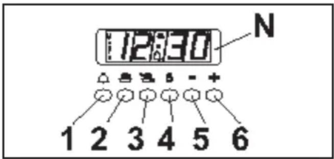
ELECTRONIC PROGRAMMER
The programmer can select the following functions:
- Clock (set by keys 2 and 3)
- Minute counter (set by key 1)
- Cooking time (set by key 2)
- End of cooking (set by key 3)
- Manual operation mode (set by key 4)
- Setting time backwards (set by key 5)
- Setting time forward (set by key 6)
The digital display (N) always shows the time and can display cooking and end of cooking time or the minute counter time by pressing the corresponding push button.
N.B.: At the end of each setting session (except for the minute counter) the programmer turns the oven off. Check when next using the oven, if the programmer is not going to be used, that the latter is set on manual operation (see the instructions given further on).
Setting the time (from 0.01 to 24.00 = hh, mm)
After connecting to the electricity mains or subsequent to a power cut, AUTO and "0.00" will both flash simultaneously on the display.
Press push buttons 2 and 3 simultaneously and start setting the current time by pressing push button 5 or 6.
Once set the AUTO symbol will turn off and
the symbol, for manual operation, will turn on.
Minute counter (from 0.01 to 0.59 = hh, mm)
Press push button 1 and select cooking time with push button 5 or 6. The 🔒 symbol turns on. At the end of the set time the buzzer will go off and the 🔒 symbol turns off.
Semi-automatic operation
(with cooking time from 0.01 to 23.59 = hh, mm) By pressing push button 2 and setting the length of cooking time with push button 5 or 6, the AUTO and symbols will light up and stay on all the time. At the end of the set time the symbol will turn off, the AUTO symbol will flash and the buzzer will go off.
Semi-automatic operation
(with end of cooking time from 0.01 to 23.59 = hh, mm)
By pressing push button 3 and setting the end of cookingtimewithpushbutton6,theAUTOand symbols will turn on and stay on all the time. At the end of the set time the symbol will turn off, the AUTO symbol will flash and the buzzer will go off.
Oven Setting:
After setting a program, turn the oven function selection knob to the desired oven function and set the oven thermostat knob to the desired cooking temperature.
Automatic operation
(with the start of cooking time delayed)
First programme cooking time (both the AUTO and symbol will turn on) and then the end of cooking time (the symbol will turn off) as described previously. The symbol will turn on again when baking in the oven starts. At the end of cooking time the symbol will turn off, the AUTO symbol will flash and the buzzer will go off.
Manual operation
Manual operation is only possible when the automatic programming has finished or after having cancelled it by pressing push button 4. The AUTO symbol disappears and the Aabove mentioned symbol turns on.
Buzzer
The buzzer will go off at the end of a programme or at the end of the minute counter function and lasts about 7 minutes. The buzzer can be stopped by pressing one of the function push buttons.
Programme start and control
The programme starts after setting. The programme set can be controlled at any time by pressing the corresponding push button.
Correcting/cancelling the programme setting An automatic function programming error will occur if the time shown on the clock is between the cooking start time and cooking end time. This error will be signalled immediately by a buzzer and the AUTO symbol will flash. A setting error can be corrected by altering the duration or end of cooking time. Any programme that has been set can be corrected at any time by pressing the corresponding programming key and then key 5 or 6. To cancel a programme, correct the time set bringing it to a value of "0.00". If functioning time is cancelled the end of functioning is cancelled too and vice versa. The oven turns off automatically and the AUTO symbol flashes. Press key 4 to set the programmer on manual operation. The right time cannot be corrected when the automatic operation programme is working.
INSTRUCTIONS FOR THE USER
HOB: GENERAL NOTES ON SAFETY
- When using the burners, do not leave the appliance unsupervised. Ensure that children and the infirm do not play with the appliance. In particular, make sure that pan handles are positioned correctly and supervise the cooking of foods which use oils and fats, as these are highly inflammable.
- Do not use aerosols or sprays near the appliance when it is in use.
- Even after use, the burners remain hot for a long period; to avoid burning, do not place hands or other objects on them.
- After using the appliance, ensure that all the controls are in the closed or off position.
AUTOMATIC ELECTRIC IGNITION OF COOKTOP BURNERS
Push the knob (A) which corresponds to burner to be ignited and turn anti clockwise to the "Full On" position, then depress the control knob.
Automatically the ignition spark shoots. If there is no electric power the burner may be lit with matches.
OPTIMUM USE OF COOKTOP BURNERS
In order to achieve maximum efficiency with minimum gas consumption it is useful to remember:
- Do not use large burners with pans of small diameter in order to avoid flames spreading wider than pans (consult the following table) and always use pans with lids (fig. 3).
- When the boiling point is reached, it is best to turn the knob to the "Low position".
- Avoid using over sized pans that may radiate excessive heat and cause damage to surrounding surfaces such as bench tops and glass lid.
- The appliance is equipped with a particular pan support (1) on which must be put the wok support (2). To ensure stability, position the notch (A) of wok support on the pan support fingers as indicated in fig. 4.
- Do not place anything, e.g. flame tamer, asbestos mat, between pan and pan support, as serious damage to the appliance may result (fig. 5).
- Locate pan centrally over the burner so that is stable and does not overhang the appliance (fig. 6).
- If gas burns with a yellow flame, do not continue to use burner and arrange for service.
- Do not use burners without the proper pan support or wok stand, as this will concentrate and deflect the heat onto the hotplate (fig. 7) and surrounding surfaces.
- Use only a wok support supplied or recommended by the manufacturer of the appliance (fig. 8).
ABNORMAL OPERATION
Any of the following are considered to be abnormal operation and may require servicing:
- Yellow tipping of the hob burner flame.
- Sooting up of cooking utensils.
- Burners not igniting properly.
- Burners failing to remain alight.
- Burners extinguished by the oven door.
• Gas valves, which are difficult to turn.
In case the appliance fails to operate correctly, contact our Service Centre.
Warning: Servicing should be carried out only by authorised personnel.
| Burners | ∅ pan cm |
| Wok | 22 - 24 |
| Large | 20 - 22 |
| Medium | 16 - 18 |
| Small | 12 - 14 |

natural_image
Two industrial storage tanks with cross-bracing patterns, one larger and one smaller, both without any visible text or symbols.
INSTRUCTIONS FOR THE USER


natural_image
Simple line drawing of a bowl placed on a stand inside a circle, no text or symbols present.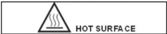
- Never cover the base of the oven or the oven shelf with aluminium foil or other materials, as this creates a fire hazard.
- When grilling always put a little water in the grill pan. The water prevents the grease from burning and from giving off bad smells and smoke. Add more water during grilling to compensate for evaporation.
• After using the appliance ensure that all the controls are in the off position. - WARNING - During and after use, the oven door glass and the accessible parts will become hot when in use. To avoid burns and scalds children should be kept away.
OVEN: GENERAL SAFETY INSTRUCTIONS
- Do not leave the oven unsupervised during use. Ensure that children and the infirm do not play with the appliance.
- Do not spray aerosols in the vicinity of this appliance while it is operating.
- Always grip the centre of the oven door when opening. Do not practice excessive pressures on the door when it is open.
- Do not store or use flammable liquids or items in the vicinity of this appliance.
- Do not worry if condensation forms on the door and on the internal walls of the oven during cooking. This does not compromise its efficiency.
- When opening the oven door, be very careful of scalding vapours.
- During use the appliance becomes hot. Care should be taken to avoid touching heating elements inside the oven. Wear oven gloves when placing or removing pans from the oven or use the handle provided. Hook the handle to the edge of the tray and pull it out, slightly lifting it as you do so.
- When inserting or removing food from the oven, check that excess juices do not overflow onto the oven base (oils and fats are highly inflammable when overheated).
- Use containers that will resist the temperatures indicated on the thermostat knob.
INSTRUCTIONS FOR THE USER
HOW TO USE THE MULTIFUNCTION OVEN
BFD9054WX is a 4 function oven with fan forced, grill, light and defrost.

DEFROSTING AT ROOM TEMPERATURE
Turn the selector knob to the symbol and place the food you want to defrost inside the oven. The length of time required depends on the quantity and type of food. Selecting this function will only activate the fan. Mild air circulation around frozen food will slowly defrost it. It is particularly suitable for fruit and cakes.

FAN + REAR HEATING COMBINED COOKING
Turn the selector knob to the symbol and set the thermostat to the desired temperature, then place your food the oven. If oven needs pre-heating wait till the thermostat yellow led turns off before placing foods inside it. This function activates the rear heating unit and the fan distributes the heat produced. This combination allows for a fast and even cooking of several different foods placed on the diverse levels of the oven.

NVETIONAL GRILL COOKING
Turn the selector knob to the symbol and set the thermostat to the desired temperature. Selecting this function the top central heating element turns on and heat is distributed directly on food surface.
Apart from grilling, this function is ideal to add a golden roast to your recipes or to toast bread slices.
When you use the grill, do not forget to place the drip pan beneath it to collect any sauce dripping, as suggested in the “USEFUL COOKING TIPS” section.
INSTRUCTIONS FOR THE USER
TIME AND TEMPERATURE CHART
The below table gives guidelines for cooking a range of different foods, individual food, or personal preferences may slightly vary the oven position, temperature and cooking time from those suggested.
Please note that:
- All cooking temperatures stated refer to a preheated oven (allow 15 minutes for preheating).
- The shelves are numbered from the bottom i.e. the top shelf is Shelf 4, bottom shelf is Shelf 1.
- If baking a larger quantity than the example shown in the chart, slightly increase temperatures and/or time.
- If baking a smaller quantity than the example, slightly decrease the temperature and/or time.
- Remember to remove grill tray from oven before baking in oven.
Please note that this oven may not have all the functions required to cook all dishes and therefore only certain recipes will apply to your oven.
| FOOD ITEM QUANTITY | OVEN POSITION | TEMPERATURE °C | APPROXIMATE TIME | |
| CAKES | ||||
| Patty cakes | 20 | Shelf 2 or 3 | 190 | 15-20 mins. |
| Sponges | 1 or 2 | Shelf 2 or 3 | 190 | 20-25 mins |
| Butter cake - slab | 1 | Shelf 2 or 3 | 190 | 30-35 mins. |
| Boiled fruit cake - 20 cm tin | 1 | Shelf 2 or 3 | 160 | 2 hrs. |
| Rich fruit cake - 20 cm tin | 1 | Shelf 2 or 3 | 150 | 4 hrs. |
| SCONES - plain | 20 Shelf 2 | 240 10-12 mins. | ||
| BISCUITS | ||||
| Anzacs | 24 | Shelf 3 or 4 | 150 | 20 mins. |
| Burnt butter biscuits | 40 | Shelf 3 or 4 | 180 | 25 mins. |
| MERINGUE - small | 20 Shelf 3 | or 4 125 | 1-1 12 hrs. allow to cool in oven | |
| PASTRIES | ||||
| Custard tart - 23 cm | 1 | Shelf 3 | 220/180 | 10/40-50 mins. |
| Fruit pies - biscuit pastry, double crust cooked filling | 1 | Shelf 3 or 4 | 210/190 | 15/15-20 mins. |
| Sausages rolls | 20 | 220 | 20-25 mins. | |
| PIZZA - yeast dough 30 cm | 1 Shelf 3 | 240 20-25 mins. | ||
| OVEN MEAL | ||||
| Roast meat & vegetables | Shelf 2 or 3 | 210 | as requested | |
| Fruit pies | 2 | Shelf 2 or 3 | 50-60 mins. | |
| BREAD | 1 loaf | Shelf 4 200 35-40 mins. | ||
RETAIN THIS CHART FOR EASY REFERENCE
ROAST MEATS
Meats are generally roasted in the centre of the oven (shelf 3) but the position may be varied according to the size of the meat and the other foods to be cooked at the same time.
A moderate temperature can be used (200°C) although superior results are often achieved by cooking meat quickly at a high temperature e.g. 250°C for 30 minutes to sear the meat, then complete the cooking on a moderate heat. Turkey or other very large joints of meat may be cooked at lower than moderate temperatures.
INSTRUCTIONS FOR THE USER
USEFUL COOKING TIPS
Cakes and bread:
- Heat the oven for at least 15 minutes before you start cooking bread or cakes.
- Do not open the door during baking because the cold air would stop the yeast from rising.
- When the cake is cooked turn the oven off and leave it in for about 10 minutes.
- Do not use the enamelled oven tray or drip pan, supplied with the oven, to cook cakes in.
- How do you know when the cake is cooked? About 5 minutes before the end of cooking time, put a cake tester or skewer in the highest part of the cake. If it comes out clean the cake is cooked.
- And if the cake sinks? The next time use less liquids or lower the temperature 10°C.
- If the cake is too dry: Make some tiny holes with a toothpick and pour some drops of fruit juice or spirits on it. The next time, increase the temperature 10irc C and set a shorter cooking time.
- If the cake is too dark on top: the next time put the cake on a lower shelf, cook it at a lower temperature and longer.
- If the top of the cake is burnt: cut off the burnt layer and cover with sugar or decorate it with cream, jam, confectioner's cream, etc.
- If the cake is too dark underneath: the next time place it on a higher shelf and cook it at a lower temperature.
- If the cake or bread is cooked nicely outside but is still uncooked inside: the next time use less liquids, cook at a lower temperature and longer.
- If the cake will not come out of the tin: slide a knife around the edges, place a damp cloth over the cake and turn the tin upside down. The next time grease the tin well and sprinkle it with flour or bread crumbs.
- If the biscuits will not come away from the baking tray: put the tray back in the oven for a while and lift the biscuits up before they cool. The next time use a sheet of baking parchment to prevent this happening again.
Meat:
- If, when cooking meat, the time needed is more than 40 minutes, turn the oven off 10 minutes before the end of cooking time to
exploit the residual heat (energy saving).
- Your roast will be juicier if cooked in a closed pan; it will be crispier if cooked without a lid.
- Normally white meat, poultry and fish need medium temperatures (less than 200°C).
- To cook “rare” red meats, high temperatures (over 200°C) and short cooking times are needed.
- For a tasty roast, lard and spice the meat.
- If your roast is too dark on top or underneath: the next time put it on a higher or lower shelf, lower the temperature and cook longer.
- Your roast is underdone? Cut it in slices, arrange the slices on a baking tray with the gravy and finish cooking it.
Grilling:
- Sparingly grease and flavour the food before grilling it.
- Always use the grill pan to catch the juices that drip from the meat during grilling.
- Always put a little water in the drip pan. The water prevents the grease from burning and from giving off bad smells and smoke. Add more water during cooking because it evaporates.
- Turn the food half way through cooking.
- If you are grilling fatty poultry (goose) pierce the skin so the fat can drip away.
The aluminium can be easily corroded if it comes into contact with organic acids present in the foods or added during baking (vinegar, lemon juice). Therefore it is advised not to put directly the foods on aluminium or enamelled trays, but ALWAYS use the proper oven paper.
INSTRUCTIONS FOR THE USER
CLEANING AND MAINTENANCE
HOT PLATE
The burner caps and burner heads need to be cleaned after each time they are used with warm soapy water, rinsed and then dried well to keep them in good condition. WARNINGS:
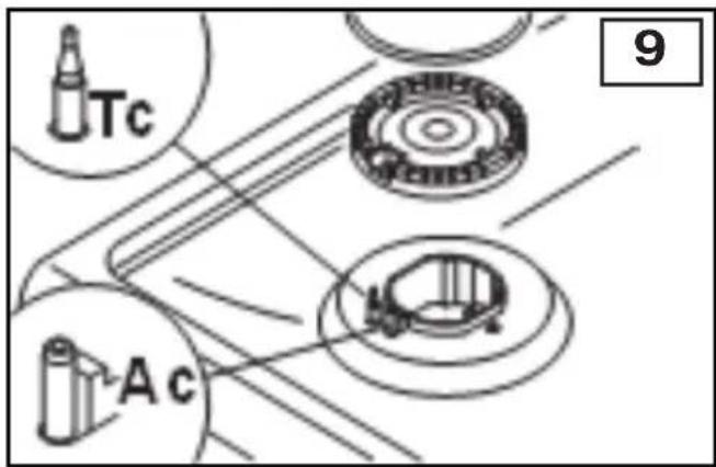
- After cleaning, check that the heads burners and the relative burner caps, are correctly positioned in their housings (fig. 9).
• Take care not to disturb the ignition spark plugs or flame failure devices. - If you find a tap is difficult to open or close do not force it but call for technical assistance urgently.
- The appliance is not intended to be operated by means of an external timer or separate remote-control system.
STRUCTURE
All the cooker parts (in enamelled or painted metal, steel, or glass) should be cleaned frequently with warm soapy water and then rinsed and dried with a soft cloth.
DO NOT use harsh abrasive cleaners or sharp metal scrapers to clean the oven glass door since they can scratch the surface, which may result in shattering of the glass. NEVER use sponges or abrasive products, and aromatic or aliphatic solvents to remove stains or adhesives on the painted or stainless steel surfaces.
OVEN CAVITY
Do not spray or wash the thermostat bulb with acid based products (check the product label before use). The manufacturer cannot be held liable for any damage caused by incorrect cleaning.
The oven cavity should be cleaned after each use to remove cooking residuals and or grease or sugar which, if burnt on when the oven is used again, will form deposits or unremovable stains as well as unpleasant smells.
To maintain the shine of the enamelled parts, clean them with warm soapy water, rinse and dry them thoroughly. ALWAYS wash the accessories used.
OVEN SIDEWALL GRIDS (fig. L)
To allow for a better cleaning of the side grids, you can extract them this way:
- Push with a finger on the last of the slots to release the grid from its hold.
- Lift it towards the top and extract the grid. To put them back into place, reverse the order of this operation.

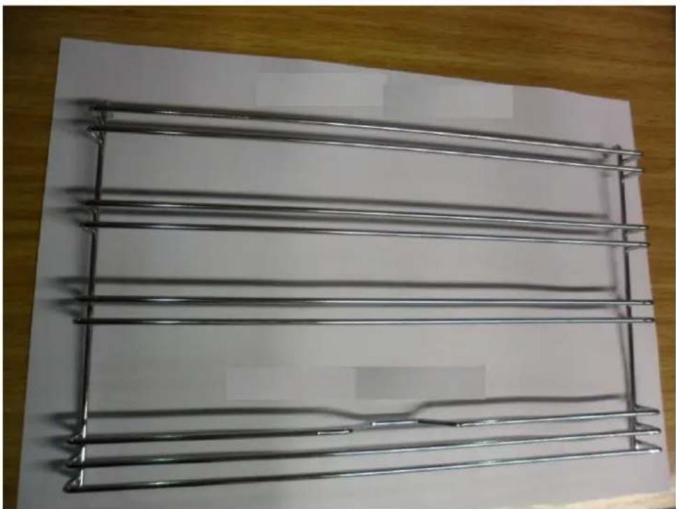
Telescopic rails assembly instructions
natural_image
Metal wire cage array on a white surface, no text or symbols visibleOven lateral chromed shelf – the shelves are ambidextrous.

natural_image
Hand holding a metal rack with wire, placed on a wooden surface (no text or symbols visible)Telescopic rail positioning: place the telescopic rail as in the picture above

natural_image
Close-up of a hand holding a metallic tool against a wooden background (no text or symbols visible)Telescopic rail insertion: press the telescopic rail so that it fits in the seat, opening the tabs on both sides.

natural_image
Close-up of a metallic metal ladder with visible railings and a small white object on the surface (no text or symbols)Once the guide is properly inserted, the tabs go back into place and lock the telescopic rail to the lateral shelf.

In order to distinguish between right and left rail, make sure that the telescopic rails open sliding in the opposite direction one another.

In order to extract the telescopic rail, pull the tabs on both sides.

Open the tabs and pull out the telescopic rail by pulling upwards.

Telescopic rail extracted.
INSTRUCTIONS FOR THE USER
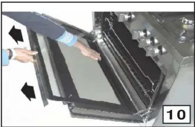
HOW TO CLEAN THE INNER OVEN DOOR GLASS One of the features of our cookers is that the inner oven door glass can be easily removed for cleaning without the aid of specialized personnel. Just open the oven door and remove the support securing the glass (fig. 10).
ATTENTION!!
This operation can be done also with the door fitted on appliance, but in this way, pay attention that when the glass is pull upwards, the force of the hinges can close the door roughly. LOCK AT LEAST ONE HINGE.
OVEN DOOR REMOVAL
The oven door can be removed to give easier access to the oven when cleaning. To remove, proceed as follows:
- Open the oven door and insert rivet (R) in the hole (F) of the hinge (fig. 11).
- Partially close the door, forcing it upwards at the same time to free stop tooth and hinge sector.
- Once the hinge is free, pull the door forwards tilting it slightly upwards to free sector.
• To reassemble proceed in the reverse order, paying attention to the correct position of sectors.
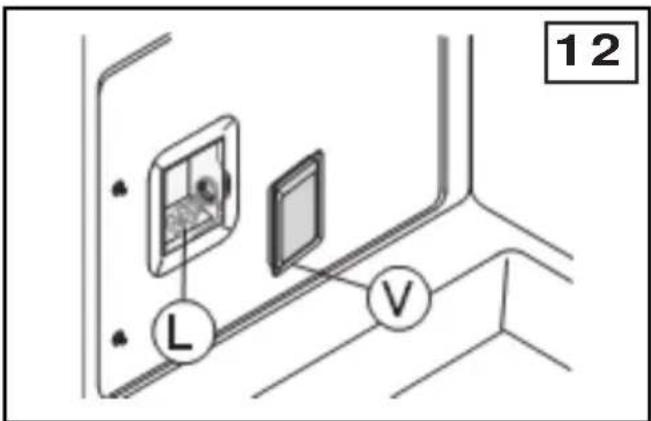
REPLACING THE OVEN LAMP (fig.12)
WARNING: Ensure the appliance is switched off before replacing the lamp to avoid the possibility of electric shock.
In the event the oven lamp needs replacing, the new lamp must comply with the following requisites:
15 W - 230 V\~ - 50 Hz - E 14 - and must be resistant to high temperature (300°C).
To change the oven lamp follow the instructions :
- Draw out the side guide rails as described above. Then remove the glass protection cap (V) from the bulb socket, lifting it with a screwdriver placed between the cap and the oven wall and replace the lamp (L). Fit the accessories back in reverse order.
OVEN SEAL
The oven seal guarantees the correct functioning of the oven. We recommend you:
- clean it, avoiding abrasive tools or products.
- check its state now and then.
If the oven door seal has become hard or is damaged, contact our Service Centre and avoid using the oven until it has been repaired.
natural_image
Person interacting with a large transparent panel or enclosure, showing internal structure and arrows indicating movement (no text or symbols visible)
MAINTENANCE SCHEDULE NO REGULAR MAINTENANCE IS RE- QUIRED EXCEPT FOR CLEANING
TROUBLESHOOTING
Some problems can be caused either as the results of simple maintenance operations or by incorrect selection of settings. Prior to contacting a Service Centre please check the following chart.
| PROBLEM | REMEDY |
| The appliance is not working | Make sure the gas cock is openCheck the plug is inCheck that the knobs are set correctly for cooking and then repeat the operations given in the handbookCheck the electrical system safety switches (RCD). If there is failure in the system call an electrician in. |
| The thermostat is not working | Contact Service Centre. |
| The oven light does not switch on | Make sure the lamp is firmly screwed in placeBuy a lamp for high temperatures at one of our Service Centre and fit it following the instructions given theparagraph. |
| Warning: Servicing should be carried out only by authorised personnel. | |
INSTRUCTIONS FOR THE INSTALLER
TECHNICAL INFORMATION
- The installations, conversions and maintenance operations listed in this part must only be carried out by authorised personnel. The manufacturer cannot be held responsible for any damage to persons or property resulting from an incorrect installation of the appliance.
- If the appliances is installed on a base, measures must be taken to prevent the appliance from slipping from the base
-
The appliance is not intended to be operated by means of an external timer or separate remote-control system.
-
The safety and automatic adjustment devices of the appliances may, during its life, only be modified by the manufacturer or duly authorised supplier.
- This appliance shall be installed only by authorised personnel and in accordance with the manufacturer's installation instructions, local gas fitting regulations, municipal building codes, electrical wiring regulations, AS 5601 - Gas Installations and any other statutory regulations.
- Failure to install the appliance correctly could invalidate any manufactures warranty and lead to prosecution under the above quoted regulation.
- Before installation, make sure that local distribution conditions (gas and electrical) are compatible with the appliance's adjustment. Refer to data label for gas type.
- As it is not connected to a device for the evacuation of the products of combustion, it
must be installed in accordance with current regulations and used in a well ventilated location. Particular attention must be paid to the regulations on ventilation.
VENTILATION
All rooms require an openable window or equivalent, while some rooms require a permanent vent in addition to the openable window.
Ventilation must be in accordance with AS5601
- Gas Installations. In general, the appliance should have adequate ventilation for complete combustion of gas, proper flueing and to maintain temperature of immediate surroundings within safe limits.
The use of a gas appliance results in production of heat and moisture in the room in which it is installed. Ensure that the kitchen is well ventilated; keep natural ventilation holes open or install a mechanical ventilation device (mechanical extraction hood).
Prolonged intensive use of the appliance may call for additional ventilation, for example increasing the level of mechanical ventilation where present. UNPACKING YOUR COOKER
- Once the packaging has been removed, thoroughly check that the appliance is in perfect condition. If you have any doubts do not use the appliance and call our Service Centre.
- Do not move the appliance by the handles.
- Some parts mounted on the appliance are protected by a plastic film. This protection must be removed before using the appliance. We recommend slitting the plastic film along the edges with a sharp knife or pin.
The packaging materials used (cardboard, plastic bags, polystyrene foam, nails etc.) must not be left anywhere within easy reach of children as they are a potential hazard source.
INSTRUCTIONS FOR THE INSTALLER
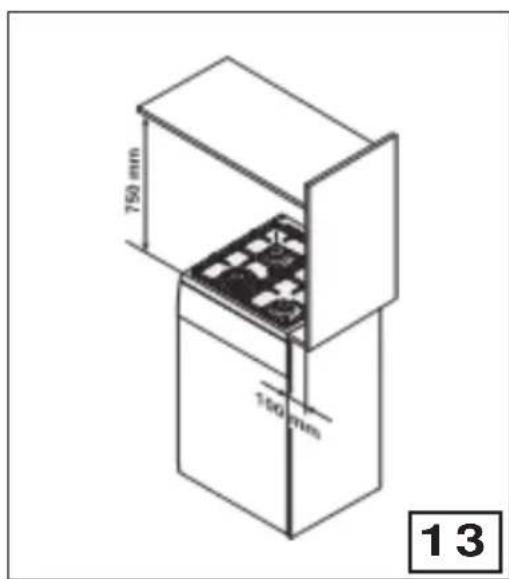
POSITION (fig. 13)
The appliance should be positioned in good light and free from draughts. Any adjoining wall surface situated within 200 mm from the edge of any hob burner must be a suitable non-combustible material for a height of 150 mm for the entire length of the hob. Any combustible construction above the hotplate must be at least 750 mm above the top of the burner and no construction shall be within 450 mm above the top of the burner.
Where a combustible surface adjacent to the cooker is less than 200 mm from the nearest burner it may be protected by a non-combustible protective layer in accordance with AS5601. The protection must ensure the surface temperature of the combustible surface does not exceed 65°C above ambient.
- Adjustable feet, This model has adjustable feet which can go from a height of 870 - 930mm (excluding splashback of 60mm) depending on how you adjust them.
- Backguard. The cookers which are equipped with this accessory, leave the factory with this part inserted inside the packaging. In order to install the backguard, it is necessary to loosen the screws positioned on the back of the hob and then to fix the backgaurd as indicated in figure 16.
OVERALL DIMENSIONS (fig. 14)
870 - 930H x 900W x 600D mm
It is essential to check dimensions of physical product when measuring for installation and before doing any cut outs.


natural_image
Simple line drawing of a mechanical or structural component with a curved arrow indicating rotation (no text or symbols)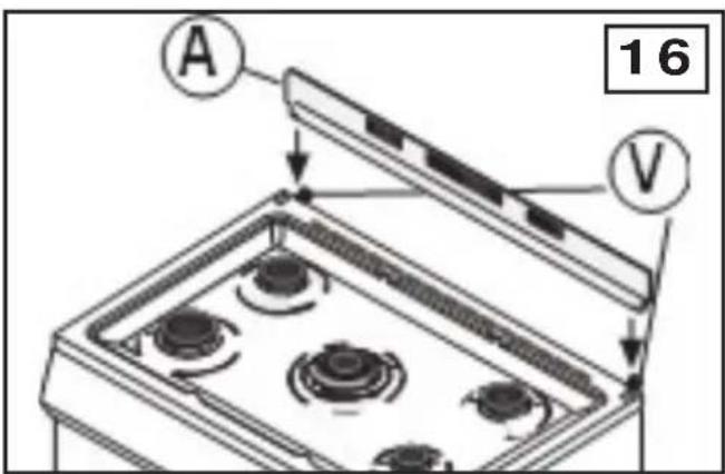
INSTRUCTIONS FOR THE INSTALLER
INSTRUCTION FOR STABILIZING THE COOKER
The installation of the brackets provided is for safety reasons and must be installed as indicated below.
EQUIPMENT QUANTITY

WARNING: In order to prevent the cooker tipping forwards in the event of children standing on the oven door or where users put extreme weight on the door when in open position, the stabilising means must be installed by the installer. Failure to fit the stabilising brackets properly may cause personal burn injuries and damage to the gas pipe.

Fix the bracket on the cooker.
One for each side.
Align the cooker with the surrounding cupboard.
Measure the distance from the floor and from the fixing point of the bracket.(X)
INSTRUCTIONS FOR THE INSTALLER

Mark it the same distance, (X) on back wall.

natural_image
Technical illustration of a metal bracket mounted on a brick wall, labeled (fig.3) (no text or symbols on the diagram itself)Drill two holes in the wall for each bracket according to the fig. 2 and fix the bracket.

Push back the cooker against the wall.
IMPORTANT: After fitting the stabilising brackets and pushing the cooker into position, check that the cooker does not tilt forward or sideways
Hose Restraint Chain
The installer must fit a chain, no more than 80% of the hose length to ensure that there is no strain on the hose when the cooker is pulled forward. Attach one end of the chain as close as possible to the gas inlet on the cooker and the other end as close as possible to the gas outlet on the wall. Suitable chain and fittings are to be supplied by the installer.
INSTRUCTIONS FOR THE INSTALLER
GAS CONNECTION
This appliance shall be installed only by authorised personnel and in accordance with the manufacturer's installation instructions, local gas fitting regulations, municipal building codes, water supply regulations, electrical wiring regulations, AS 5601 - Gas Installations and any other statutory regulations.
The appliance is adjusted to work with the gas indicated on the label which is applied on the glass-window of the oven door and on the cooker packing.
Installation for Natural gas
Connect regulator (B) to fitting (A) which is then fitted to elbow (F). Ensure arrow on regulator point in the direction shown. Fitting (D) to be supplied by installer (fig. 18). Adjust regulator to give test-point pressure given on data label on
The stove must be installed on legs which come with the product, a gas pipe between fitting (A) and (B) will allow location of the regulator (B) underneath the stove for adjustment and maintenance.
Installation for Propane Gas (fig. 18A)
Connect by using a copper pipe starting, from the threaded fitting of elbow (F).
Installation using flexible connection
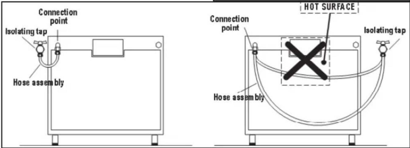
As an option, the cooker may be installed with a flexible connection hose, which complies with AS/NZS 1869 (AGA Approved), 10 mm ID, class B or D, Minimum 1000 mm - Maximum 1200 mm, as an alternative connection.
- All cookers offer left or right hand connection. The manifold has a flat flair over which is inserted a screw nut male 12 " gas (fig. 18B).
- An isolating tap and pressure regulator must be fixed to the rear wall and the flexible pipe attached by means of a union connector.
- The gas connection and isolating tap must be accessible to a service person or inspector.
- The hose assembly must be installed in accordance with AS5601 for a high level connection. The hose should not be subjected
to abrasion, kinking or permanent deformation and should be able to be inspected along its entire length. Unions compatible with the hose fittings must be used and connections tested for gas leaks. The fixed consumer piping outlet should be at approximately the same height as the cooker connection point, pointing downwards.
- The hose should be clear of the floor when the cooker is in the installed position. The anti-tilting chain supplied should be anchored to the lower hook fixed to the wall so that the chain prevents strain on the hose connections when the cooker is pulled forward.
Note: When the regulator is fitted at the rear of the cooker at least 60 mm clearance is required.


INSTRUCTIONS FOR THE INSTALLER
ELECTRICAL CONNECTION
The appliance is supplied with a 15A power plug fitted to the supply cord. Connect the plug to a 15A General Purpose Outlet (GPO) which is properly earthed and installed by an authorised electrician. If a 15A GPO is not available then an authorised electrician must install the appliance as follows:
FIXED WIRING.
The electrical connection must be carried out in accordance with the current standards and laws in force and by an authorised electrician.
- Warning this appliance must be earthed.
- Connection to the electricity supply must be made by an authorised electrician to a suitable isolating switch in accordance with the requirements of SAA Wiring Rules, AS/NZS 3000.
- A H05 RR-F 3x1.5 mm2 cable must be used.
- Means of disconnection shall be provided in the fixed wiring in accordance with the Australian wiring rules.
- Remember that the earth wire must be longer than the phase wires.
- Note: The power supply cable must be positioned so that no part of cable can come into contact with any surface which could reach temperatures in excess of 75 K.
- If the supply cord is damaged, it must be replaced by the manufacturer, its service agent or similarly qualified persons in order to avoid a hazard.
ADJUSTMENTS
- Always disconnect the appliance from the electricity supply before making any adjustment.
- All seals must be replaced by the technician following any adjustment or regulation.
- The adjustment of the reduce rate (simmer) must be undertaken only with burners functioning on natural gas while in the case of burners functioning on Propane, the screw must be locked down fully (in clockwise direction).
- "Primary air adjustment" on hob gas burners is unnecessary.
- If the appliance cannot be adjusted to perform correctly refer to the authorised service provider in your area.
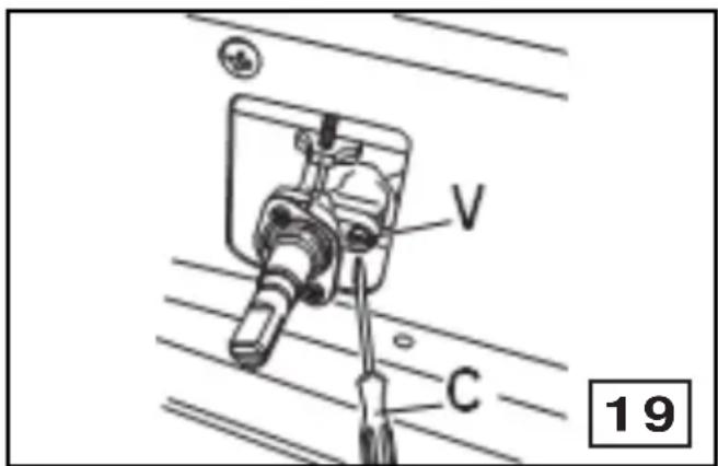
TAPS (fig. 19)
All gas taps are male cone type with only one way of passage. The adjustment screw (V) is on the side of the stem.
Adjustment of the “Reduced rate” position as follows:
- Turn the burner on and place the knob on the "Reduced rate" position (small flame).
- Remove the knob of the tap which is attached by simply applying pressure to the rod.
- With a small screwdriver (C) turn to the right or left the adjustment screw (V) until the flame of the burner is conveniently regulated to the Low position.
- Check that the flame does not go out when the knob is sharply switched from the "Full on" to "Reduced rate" positions.
Hot Plate Ignition Failure
- Check alignment of burner holes to electrode.
- Check aeration sleeve for adjustment for gas type, location and ambient conditions.
- No spark, check ignition box failure or power supply.
Before Leaving
- Check all connections for gas leaks with soap and water. DO NOT use a naked flame for detecting leaks. Ignite all burners to ensure correct operation of gas valves, burners and ignition.
- Turn gas taps to low flame position and observe stability of the flame. When satisfied with the cooker, please instruct the user on the correct method of operation.
- In case the appliance fails to operate correctly after all checks have been carried out, refer to the authorised service provider in your area.
CHANGING THE FLEXIBLE GAS HOSE
In order to guarantee that the gas hose is always in excellent condition we strongly recommend changing it on the date you will find printed on it.
INSTRUCTIONS FOR THE INSTALLER
GAS CONVERSIONS
REPLACING THE INJECTORS
Our burners can be adapted to different types of gas by simply installing the injectors suitable for the gas you want to use. To help the installer, the table (see TECHNICAL FEATURES paragraph) gives the burner nominal heat input, injector diameter and operating pressure of the different gas types. Comply with the following instructions: Injector replacement - Hob burners.
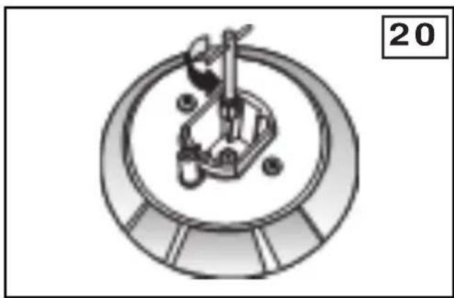
To change the injectors on the hob, remove the burner cup and head and with a 7 mm ∅ socket spanner replace them (fig. 20).
After having replaced the injectors, it will be necessary to proceed with burner adjustment as explained in the previous paragraphs.
REPLACING COMPONENT
THE
ELECTRICAL
- The rear protection will have to be removed in order to change the electrical heating elements, spit motor, terminal board and power cable.
- If you have to change the power cable (see TECHNICAL FEATURES paragraph), always keep the earth wire longer than the phase wires and, in addition, follow all the instructions given in the “ELECTRICAL CONNECTION” paragraph.
• To change the oven lamp see the instructions REPLACING THE OVEN LAMP paragraph.
- To change lamp holder (P) (fig. 21), use a screwdriver to push the clamp tips (M) and pull the lamp holder out towards the inside of the oven.
- To change the lamp holder, the spark generator and the spark electrodes, the work top has to be removed as indicated in the paragraph «REPLACING THE TAPS».
- To change the programming accessory, the thermostat, the commutator and the warning lights, remove the front panel by unscrewing the three fixing screws which lock it to the front frame.
natural_image
Mechanical component diagram showing a circular assembly with internal components and mounting holes (no text or symbols)
INSTRUCTIONS FOR THE INSTALLER
MAINTENANCE
Prior to any maintenance work or changing parts, disconnect the appliance from the gas and electricity power sources. Servicing must only be carried out by authorised personnel.
REPLACING THE TAPS
Proceed in the following way when replacing a tap • Remove pan supports, burner heads.
- Unscrew the burner fixing screws (Vc) (fig. 22). (four for ultrarapid burner and two for the other burners)
- Pull out the knobs.
- Remove the hob, unscrewing frontal and rear fixing screws (Vs) (fig. 22) which lock the hob at the supports (S).
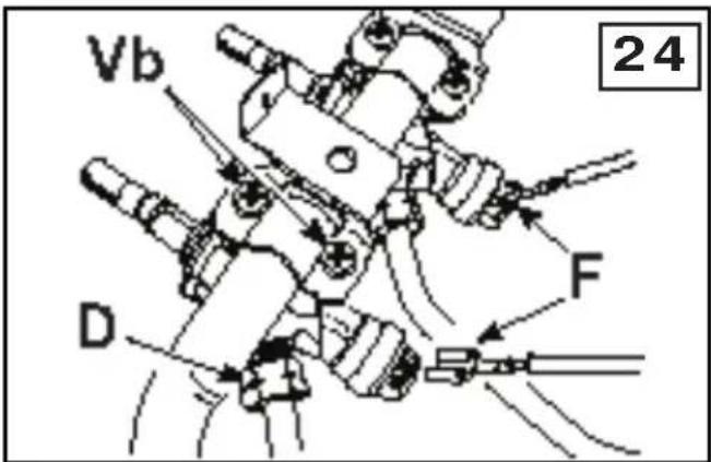
- Unscrew the nuts (D) of the gas aluminium pipes and pull out the thermocouple quick connectors (F) (fig. 24).
- Unscrew the screws (Vt) (fig. 23) which lock the crosspieces.I
- Unscrew the screws (Vb) (fig. 23) which unite the the bridles of the taps to the front frame.
- Make to slip the ramp toward the back part and unscrew the screws (Vb) (fig. 24) in order to free the taps.
- Change seal each time a tap or a thermostat is replaced. This will ensure perfect retention between the tap or a thermostat and part.
- Reassemble all the parts following the same procedure but in the reverse order.


TECHNICAL FEATURES

BURNERS DISPOSITION AND TECHNICAL DATA TABLE
| N. BURNER GAS | Operating Pressure kPa | Diameter Injectors 1/100 mm | Rating MJ/h | ||
| 2 | LargeLeft front | Propane/U-LPGNatural gas | 2.751.00 | 88142 | 10.010.0 |
| 3 | MediumRight rear | Propane/U-LPGNatural gas | 2.751.00 | 73120 | 7.27.2 |
| 4 | SmallRight front | Propane/U-LPGNatural gas | 2.751.00 | 5490 | 3.84.0 |
| 6 | WokCenter | Propane/U-LPGNatural gas | 2.751.00 | 105175 | 14.615.0 |
| ELECTRICAL COMPONENTS DESCRIPTION NOMINAL DATA | |
| Circular rear heating element of the oven | 2000 W |
| Griill heating element of the oven | 2000 W |
| Oven lamp | 15 W - E 14 - T 300 |
| Oven cooling fan | 12 W |
| Fan of the rear heating element | 25..29 W |
| Supply cable | H05 RR-F 3 x1.5 mm 2 |
| GAS TECHNICAL DATA NATURAL GAS | BFD9054WX | PROPANE BFD9054WX |
| Operating pressure gas kPa 1.00 2.75 | ||
| Total input gas MJ 43.4 42.8 |
| ELECTRICAL TECHNICAL DATA | ||
| Voltage - Frequency 240 V~ 50 Hz | ||
| Total rating electrical 2060 W | ||
TECHNICAL FEATURES

WIRING DIAGRAM COOKER BFD9054WX
We appreciate your feedback. Please review our products on www.blanco-australia.com
AUSTRALIAN & NEW ZEALAND PRODUCT WARRANTY
STATEMENT OF STANDARD WARRANTY CONDITIONS
AUSTRALIAN CUSTOMERS
Our goods come with guarantees that cannot be excluded under the Australian Consumer Law. You are entitled to a replacement or refund for a major failure and for compensation for any other reasonably foreseeable loss or damage. You are also entitled to have the goods repaired or replaced if the goods fail to be of acceptable quality and the failure does not amount to a major failure.
NEW ZEALAND CUSTOMERS
Nothing herein contained shall be construed in any way as excluding or limiting your rights under the Consumer Guarantee Act 1993.
OUR WARRANTY
This product is also covered by the manufacturer's warranty set out in this document (Our Warranty).
Our Warranty is for a period of twenty four (24) months from the date of purchase and for dishwasher & refrigeration appliances will have an additional thirty six (36) months after the first twenty four (24) months on the wash motor for dishwashers & on the Sealed System (PARTS only Compressor & condenser etc) for refrigeration appliances. The labour cost to replace these parts is the responsibility of the customer.
This is in addition to (and does not exclude, restrict or modify) any rights or remedies to which you may already be entitled under the Australian consumer Law or the New Zealand Consumer Guarantee Act 1993 relating to this product.
Our Warranty (which is subject to the conditions below) covers rectification free of charge of any fault arising from defective materials or components, or faulty workmanship. The product will be repaired or replaced at the option of Blanco, and all costs of installation, removal, cartage, freight travelling expenses and insurance are to be paid by the customer.
Our Warranty is subject to the following conditions:
-
That the purchaser contact Blanco prior to any product repair.
-
That the purchaser carefully follows all instructions provided with the product and complies with all relevant electrical & plumbing regulations in their State when installing the product.
-
That the purchaser carefully follows the instructions provided in the owner's handbook relating to the proper use and care of the product and does not use the product for any purpose other than the DOMESTIC use for which it has been designed. If the appliance is used in commercial applications or for rental purposes, Our Warranty is limited to a warranty of Twelve (12) months covering all parts with Three (3) months on any labour cost of service or repair.
SERVICE AREA
The provision of service under Our Warranty is limited by the boundary/territory area of the nearest service centre. Travelling cost incurred for service outside this area is not covered by Our Warranty and service will incur commercial cost to be paid by the customer regulated by the number of kilometres travelled beyond the service area. These costs will be disclosed to you for acceptance by you prior to your claim being processed.
Microwave ovens must be returned to your nearest Authorised Service Centre for repair as they are a carry in serviceable appliance.
WHAT IS COVERED: By Our Warranty
During the warranty period, Blanco or its authorised Service Centre will at no extra charge, if your appliance is readily accessible without the need of special equipment and subject to the terms and conditions of this warranty, repair or replace any parts which it considers defective.
WHAT IS NOT COVERED: By Our Warranty
-
Products installed damaged or incomplete or not in compliance with the relevant electrical & plumbing regulations in their State.
-
Normal wear and tear e.g. cleaning, light globes, filters etc.
-
Failure resulting from power surges and electrical storms.
-
Insect or vermin infestation.
-
Unauthorised repairs or use of non genuine Blanco parts.
-
Any failure caused by the product not being used in accordance with the instruction and the installation manual provided with the product.
-
Misuse or abuse, including failure to properly maintain or service.
-
The clearing of blockages in pumps and hoses.
-
Damage which occurs during delivery or installation.
-
Claims to product surface coating due to liquid or solid spill-overs, accidental damage or damage caused from cleaning products not recommended by Blanco.
HOW TO CLAIM OUR WARRANTY
You will need to contact Blanco in Australia or New Zealand by using the contact details below.
IN AUSTRALIA
Blanco is distributed by Shriro Australia Pty Ltd
Locked Bag 5002, Kingsgrove, NSW, 2208
Phone: 1300 795 572 Fax: 1800 686 413
Email: customercare@shiro.com.au
Web: http://www.blanco-australia.com/
IN NEW ZEALAND
Elanco is distributed by Monaco Corporation
(Member of Shriro Australia Pty Ltd)
PO Box 4399, Shortland St, Auckland, 1140
Phone: 09 415 6000 Fax: 09 415 7060
Email: service@shriro.com.au
Web: http://www.bianco-australia.com/
Note: Please complete the following details when you have unpacked the product and staple this card with the purchase invoice or sales docket.
Model No.
Date of Purchase.
Serial No.
Retailer.
Affix spare rating plate of the product here or on easily accessible area or in an adjacent cupboard or similar.
*Due to continual product development the information provided may not final and may be subject to change.
- ASSISTANCE AND SPARE PARTS
- IMPORTANT NOTICE
- CONTENTS
- IMPORTANT NOTES AND PRECAUTIONS FOR USE
- DESCRIPTION OF THE APPLIANCE
- PRESENTATION
- DESCRIPTION OF THE CONTROLS
- OVEN ELECTRIC THERMOSTAT KNOB (B)
- OVEN FUNCTION SELECTOR KNOB (4) (C)
- YELLOW WARNING LIGHT
- RED WARNING LIGHT
- ELECTRONIC PROGRAMMER
- INSTRUCTIONS FOR THE USER
- HOB: GENERAL NOTES ON SAFETY
- AUTOMATIC ELECTRIC IGNITION OF COOKTOP BURNERS
- OPTIMUM USE OF COOKTOP BURNERS
- ABNORMAL OPERATION
- OVEN: GENERAL SAFETY INSTRUCTIONS
- TIME AND TEMPERATURE CHART
- Please note that:
- RETAIN THIS CHART FOR EASY REFERENCE
- ROAST MEATS
- USEFUL COOKING TIPS
- Cakes and bread:
- Meat:
- Grilling:
- CLEANING AND MAINTENANCE
- HOT PLATE
- STRUCTURE
- OVEN CAVITY
- OVEN SIDEWALL GRIDS (fig. L)
- Telescopic rails assembly instructions
- ATTENTION!!
- OVEN DOOR REMOVAL
- OVEN SEAL
- TROUBLESHOOTING
- INSTRUCTIONS FOR THE INSTALLER
- TECHNICAL INFORMATION
- VENTILATION
- POSITION (fig. 13)
- INSTRUCTION FOR STABILIZING THE COOKER
- Hose Restraint Chain
- GAS CONNECTION
- Installation for Natural gas
- ELECTRICAL CONNECTION
- FIXED WIRING.
- ADJUSTMENTS
- TAPS (fig. 19)
- Hot Plate Ignition Failure
- Before Leaving
- CHANGING THE FLEXIBLE GAS HOSE
- GAS CONVERSIONS
- REPLACING THE INJECTORS
- REPLACING COMPONENT
- MAINTENANCE
- REPLACING THE TAPS
- TECHNICAL FEATURES
- AUSTRALIAN & NEW ZEALAND PRODUCT WARRANTY
- STATEMENT OF STANDARD WARRANTY CONDITIONS
- AUSTRALIAN CUSTOMERS
- NEW ZEALAND CUSTOMERS
- OUR WARRANTY
- SERVICE AREA
- WHAT IS COVERED: By Our Warranty
- WHAT IS NOT COVERED: By Our Warranty
- HOW TO CLAIM OUR WARRANTY
- IN AUSTRALIA
- IN NEW ZEALAND
Brand : BLANCO
Model : BFD9054WX
Category : Cooker