
CEN-WAP-ABG-POE-PWE - Access Point Crestron - Free user manual and instructions
Find the device manual for free CEN-WAP-ABG-POE-PWE Crestron in PDF.


| Product Type | Wireless Access Point |
| Brand | Crestron |
| Model | CEN-WAP-ABG-POE-PWE |
| Wireless Standards | IEEE 802.11a/b/g |
| Frequency Bands | 2.4 GHz and 5 GHz |
| Maximum Data Rate | 54 Mbps |
| Power over Ethernet (PoE) | Yes, PoE+ (IEEE 802.3at) |
| Power Supply | PoE+ or external 24V DC (optional) |
| Power Consumption | 15.4 W typical |
| Dimensions (W x D x H) | 8.5 x 8.5 x 1.5 in (216 x 216 x 38 mm) |
| Weight | 1.2 lb (0.54 kg) |
| Mounting | Ceiling or wall mount (bracket included) |
| Antenna Type | Internal omnidirectional |
| Management | Web interface, Crestron toolbox |
| Security Features | WEP, WPA, WPA2, 802.1X |
| LED Indicators | Power, LAN, WLAN activity |
| Operating Temperature | 32°F to 104°F (0°C to 40°C) |
| Storage Temperature | -4°F to 140°F (-20°C to 60°C) |
| Humidity | 10% to 90% non-condensing |
| Compliance | FCC, CE, RoHS |
| Maintenance | Clean with dry cloth, avoid liquids |
| Spare Parts | Contact Crestron for replacement parts |
Frequently Asked Questions - CEN-WAP-ABG-POE-PWE Crestron
User questions about CEN-WAP-ABG-POE-PWE Crestron
0 question about this device. Answer the ones you know or ask your own.
Ask a new question about this device
Download the instructions for your Access Point in PDF format for free! Find your manual CEN-WAP-ABG-POE-PWE - Crestron and take your electronic device back in hand. On this page are published all the documents necessary for the use of your device. CEN-WAP-ABG-POE-PWE by Crestron.
USER MANUAL CEN-WAP-ABG-POE-PWE Crestron
Crestron Best Practices for Installation and Setup of Crestron RF Products
Reference Guide
This document was prepared and written by the Technical Documentation department at:

CRESTRON®
Crestron Electronics, Inc.
15 Volvo Drive
Rockleigh, NJ 07647
1-888-CRESTRON
Contents
Best Practices for Installation and Setup of Crestron RF Products 1
Introduction ...... 1
Wireless Characteristics .... 1
RF Channels 3
Installing RF Devices 5
Creating a Network List 5
Conducting a Site Survey 6
Building a Channel Map....10
Installing and Configuring RF Gateways 13
Verifying Connectivity....15
Improving Wi-Fi Network Performance....16
Increasing Reliability....16
Improving Reconnection Time....16
Troubleshooting RF Devices 17
Further Inquiries 18
Appendix: Channel Map Worksheet....19
Best Practices for Installation and Setup of Crestron RF Products
Introduction
This document outlines the Crestron ® recommended practices for installing and troubleshooting Crestron RF devices. Explanations of Crestron RF protocols and correct installation procedures are provided.
Unlike Cresnet ® or Ethernet networks that use a physical medium of transmission, ensuring connectivity and eliminating interference in a wireless network is much more difficult. Wireless networks require a significant amount of planning compared to hard-wired networks. Many additional factors affecting the strength and reliability of RF signals must be taken into consideration, including walls, furniture, other electronic equipment, and even people.
Many common household electronic devices emit electromagnetic energy, which can severely degrade wireless network performance. It is therefore necessary to use special test equipment to detect the level and locations of interference present in each unique installation. The most common cause of interference problems is a direct result of installing equipment that operates on the same frequency as a cordless phone, baby monitor, or microwave oven. This document helps avoid those problems.
Wireless Characteristics
Wireless signals are transmitted and received using waves in the radio frequency (RF) spectrum, which is a portion of the electromagnetic spectrum. The long radio wavelengths allow signals to pass through solid objects such as walls. The limited range of wireless signals in the RF spectrum allows networks in different buildings on the same street to coexist. The following illustration shows the RF spectrum within the electromagnetic spectrum.
Electromagnetic Spectrum

line
| Wavelength (Meters) | RF Spectrum | | ------------------- | ----------- | | Radio | 10⁻³ | | Microwave | 10⁻² | | Infrared | 10⁻⁶ | | Visible | 10⁻⁵ | | Ultraviolet | 10⁻⁸ | | X-Ray | 10⁻¹⁰ | | Gamma Ray | 10⁻⁴² |As shown in the illustration above, the frequencies within the RF spectrum are divided into smaller portions called bands. A band is a range of frequencies that is broad enough to allow for one or more communication paths without affecting adjacent bands. Only particular transmission bands are permitted without a special license from the FCC.
Three bands are used by Crestron wireless products:
• 418-433 MHz
• 2.4 GHz
- 5.8 GHz
Crestron wireless products do not use the 900 MHz band.
Crestron wireless network types, associated bands, and related information are listed in the following table.
Crestron RF Network Table
| WIRELESS NETWORK | BAND | TYPE | GATEWAY(S) | PRODUCTS CHANNEL | |
| Wi-Fi (IEEE 802.11a/b/g) | 2.4 GHz (802.11b/g)5.8 GHz (802.11a) | Point to point CEN-WAP-ABG-1GThird-Party Wi-FiAccess Points* | TPMC-3XTPMC-4XTPMC-4XGTPMC-8XTPMC-10 | IEEE 802.11Channel 1 | |
| infiNETTM | 2.4 GHz | Mesh | C2N-MNETGW | infiNET Devices | IEEE 802.15.4Channel 26 |
| infiNET EX 2.4 | GHz Mesh CEN-RFGW-EX MLX-2 | IEEE 802.15.4 | Channel 15 | ||
| FocalPoint | 2.4 GHz | Point to point | CEN-HPRFGW | TPS-6X | IEEE 802.15.4Channel 20 |
| — | 2.4 GHz | Point to point | TPS-RFGWX | STX-1700CXP | — |
| — | 433 MHz | Point to point | CNRFGWA, MC2W | WPR-48 | — |
| — | 418 MHz | Point to point CNRFGWA-418,MC2W | ML-500/600MT-1000WPR-48 | — | |
* 802.11n access points work with Crestron products; however, since Crestron products support 802.11a/b/g, performance does not improve over 802.11g.
Devices using the same RF band can interfere with one another's communication. As shown in the table on page 2, most of the current Crestron product offerings transmit using the 2.4 GHz wireless communication band. Even though some products may not be able to communicate with each other, such as an infiNET gateway and TPMC-8X (Wi-Fi), they can create interference that degrades performance or eliminates connectivity.
Most wireless networks use the 2.4 GHz band and consequently most connectivity issues are concentrated in that band. The 2.4 GHz band is therefore the focus of this document.
RF Channels
Each RF network type divides the communication band into separate communication channels. Crestron 2.4 GHz products use two different methods to divide the band:
- infiNET, infiNET EX, and FocalPoint use 802.15.4 channel mapping, which provides 16 channels numbered 11-26. Each channel is non-overlapping, which ensures that a device communicating on one channel cannot affect devices communicating on any other channels.
NOTE: When 802.15.4 channels are referred to in this document, the reference relates to infiNET, infiNET EX, and FocalPoint technologies.
NOTE: By default, the Crestron TPS-RFGWX network does not use specific channels but rather frequency hops over the entire 2.4 GHz band. A site survey, removal of outside interference, and proper gateway installation as discussed in this manual improve the performance of the TPS-RFGWX network.
- 802.11b and 802.11g use the same Wi-Fi channel map. Eleven channels, numbered 1-11, can be used in the U.S., and more channels can be used in other countries. Each channel overlaps two channels on each side; for example, a device communicating on channel 6 causes interference to any devices communicating on channels 4, 5, 7, and 8. As a result, in this example, there are only three available non-overlapping Wi-Fi channels: 1, 6, and 11.
NOTE: 802.11a uses the 5.8 GHz band and has a different RF channel mapping than that of 802.11b and 802.11g. While 802.11a does not have a line-of-sight transmission distance as good as that of 802.11g, 802.11a often has much less interference. In a poor RF environment, 802.11a can provide a more robust solution than 802.11g.
The following illustration shows the division of the 2.4 GHz band as it relates to 802.15.4 and 802.11 channels.
2.4 GHz Wireless Network

In the preceding illustration, the three discrete 802.11 channels - 1, 6, and 11 - are shown in orange. An 802.11 device on channel 1 may interfere with an 802.15.4 device operating on channel 13 because the two channels overlap.
As was stated previously, not all 802.11 channels are available in all countries. The U.S. supports 802.11 channels 1-11, while most European nations support the full range of channels: 1-13. All 802.11 channels provide the same operational range; however, FocalPoint and infiNET EX channels on the low and high end of the band reduce their transmit power as shown in the following tables.
FocalPoint Channels and Associated Indoor Range
| CHANNEL(S) | INDOOR | RANGE |
| 11 | 190 | feet |
| 12-23 200 feet | ||
| 24 | 140 | feet |
| 25 120 feet | ||
| 26 | 100 | feet |
infiNET EX Channels and Associated Indoor Range
| CHANNEL(S) | INDOOR | RANGE |
| 11-18 | 100 | feet |
| 19-25 90 feet | ||
| 26 | 80 | feet |
Installing RF Devices
When installing RF devices, it is recommended that you perform the following steps in the order listed below:
- Create a network list.
- Conduct a site survey.
- Build a channel map.
- Install and configure RF gateways.
- Verify connectivity.
Creating a Network List
It is important to know which wireless networks are to be installed. To do so, separate all the wireless devices to be installed into individual networks based on the following guidelines:
- Do not install more than three Crestron 802.11 devices on a single network.
- Do not install more than 30 infiNET devices or more than 16 infiNET EX devices on a single network—or as specified in the manual supplied with the device.
- To reduce the distances between gateways and devices, group the devices based on their location rather than on their function. For example, instead of creating separate lighting and HVAC infiNET networks, mix and match devices based on their location.
- Place 802.11b devices (for example, TPMC-10 and TPMC-4) and 802.11g devices (for example, TPMC-3X, TPMC-4XG, and TPMC-8X) on different networks.
- When installing mesh networks such as infiNET and infiNET EX, remember that battery-operated devices such as the CHV-TSTATRF and MLX-2 do not act as repeaters and therefore do not extend the network coverage.
- To account for unexpected interference, do not exceed 75 percent of the typical indoor network range.
One gateway is required for each individual network in the installation. The channel of each network is dictated by the gateway; therefore, all client devices communicate on the same channel as the gateway.
Keep in mind that some networks have the option of using either 2.4 or 5.8 GHz bands (802.11a/b/g), such as when the TPMC-8X is used. Those networks should be treated separately from networks that must use a 2.4 GHz band (802.11 b/g), such as when the TPMC-4X is used. An example is shown in the following table.
NOTE: You can install multiple 802.11 devices on a single network. In the following table, each device is given its own network for illustrative purposes only.
Sample List of Network Products
| NETWORK TYPE GATEWAYS | |
| Wi-Fi 802.11b/g | CEN-WAP-ABG-1G (TPMC-4X)*CEN-WAP-ABG-1G (TPMC-4XG) |
| Wi-Fi 802.11a/b/g CEN-WAP-ABG-1G (TPMC-3X, TPMC-8X) | |
| 802.15.4 | C2N-MNETGW (Lighting)C2N-HPRFGW (TPS-6X)CEN-RFGW-EX (MLX-2) |
* Although the CEN-WAP-ABG-1G supports 802.11a, the TPMC-4X – which connects to the access point – supports 802.11b only. The network must operate using a protocol that all devices can support; therefore, the network is limited to 802.11b.
Once you have the list of networks, you can conduct a site survey.
Conducting a Site Survey
A wireless site survey consists of detecting the level and distribution of outside interference. A site survey often provides early detection of any issues that might be encountered in the installation and, to a large extent, dictates which wireless channels can be used in the installation. The goal of a site survey is to discover the worst-case interference scenario.
Site Survey Tools
The following tools (provided by others) are recommended to perform a site survey:
• Wi-Spy/Chanalyzer (http://www.metageek.net)
• NetStumber (http://www.netstumbler.com)
• AirMagnet (http://www.airmagnet.com)
The following sections provide an overview of each tool.
Wi-Spy/Chanalyzer
Wi-Spy is an RF spectrum analyzer built into a small USB dongle that plugs into a PC. It detects the amount of interference across the 2.4 GHz band. Two versions are available: Wi-Spy and Wi-Spy 2.4x. The 2.4x version provides better resolution of signals for improved detection.
Wi-Spy

Wi-Spy 2.4x

natural_image
Black wireless device with USB port and antenna (no visible text or symbols)Wi-Spy devices use the Chanalyzer software to report RF signals. The software can detect other wireless networks as well as 2.4 GHz cordless phones, baby monitors, and microwaves.
NOTE: Due to the large amount of interference that can come from 2.4 GHz cordless phones, baby monitors, and microwaves, it is recommended that you use a Wi-Spy device to perform wireless site surveys.
NetStumbler
NetStumbler is the most basic site survey option. NetStumbler detects nearby Wi-Fi networks using your PC's wireless network card. Wi-Fi networks account for a large part of the interference in residential installations. NetStumbler, however, cannot detect RF signals other than Wi-Fi networks – which is a significant limitation. Any issues that could arise from microwaves, cordless phones, 802.15.4 devices, or baby monitors will not be noticed if using just this tool.
Sample NetStumbler Wi-Fi Network List

By looking at the list of networks, you can calculate which channels will have the least amount of interference. As a rule of thumb, any networks with a signal strength of -60 dB or higher should be avoided. Wi-Fi networks cause interference on the channels around them as well. In the example above, channel 1 has a very large amount of interference, channel 11 has some interference, and channel 6 has very little interference.
NOTE: NetStumbler does not work on Windows Vista™. Instead of NetStumbler, you can use a free program called Inssider available at the MetaGeek website (http://www.metageek.net/products/inssider).
AirMagnet
AirMagnet is a high-end professional site survey tool often used by corporate IT departments. AirMagnet has all of the features of Wi-Spy, plus the ability to detect the type of transmitting equipment. AirMagnet can also look at the 5.8 GHz band and the 2.4 GHz band if your laptop card has an 802.11a component.
Site Survey Tasks
NOTE: Wi-Spy 2.4x is used as the site survey tool for the examples in this section. In addition, a site survey on the 2.4 GHz band is demonstrated because it often has many more problems than any other band. If your tool supports 5.8 GHz, you can perform the same site survey tasks as performed on the 2.4 GHz band.
To perform a site survey:
- Shut down all Crestron RF devices to prevent them from being detected and interpreted as outside interference.
- Place the detecting equipment in a location where the wireless equipment is to be used.
- Take a reading that is at least five minutes long to capture enough data. During the reading, turn on all electrical equipment in the vicinity, including TVs and any microwave ovens (make sure you put something in the microwave oven first!). Also, if there are cordless phones present, call the lines and pick up the phones to activate them. Most cordless phone interference is created when the phones ring and the lines are active.
- If the wireless equipment is to be used in a room greater than 1,000 square feet, repeat steps 2 and 3 in various locations within the room.
- If the wireless equipment is to be used in multiple rooms, repeat steps 1 through 4 in each room.
When the reading has completed, Chanalyzer shows the results in a clean and easy-to-read view of the signal over the entire 2.4 GHz band as shown in the following example.
Sample Chanalyzer Capture of RF Interference
heatmap
| Measurement Time (min) | Value | | ---------------------- | ----- | | 1 | -14 | | 2 | -10 | | 3 | -5 | | 4 | 0 | | 5 | 5 | | 6 | 10 | | 7 | 15 | | 8 | 20 | | 9 | 25 | | 10 | 30 | | 11 | 35 | | 12 | 40 | | 13 | 45 | | 14 | 50 | | 15 | 55 | | 16 | 60 | | 17 | 65 | | 18 | 70 | | 19 | 75 |In the graph above, the range of wireless signals is roughly -110 dBm up to -20 dBm (-20 dBm indicates a very strong signal). A good rule of thumb to follow is that if almost all of the signal is below -80 dBm, the channel is good.
Wi-Fi channels 1, 6, and 11 are highlighted in the sample site survey above. Wi-Fi networks operate on channel 1 and channel 11, and the channel 11 network is further away. By visual inspection of the graph, note that channel 6 is the most free, followed by channel 11. Wi-Fi channel 1 has some minor signals above -80 dBm, which may be fine, but may cause reliability issues for any Wi-Fi devices using that channel or any 802.15.4 devices using channels 11-14.
Cordless Phone Interference
The following sections provide examples of various types of interference.
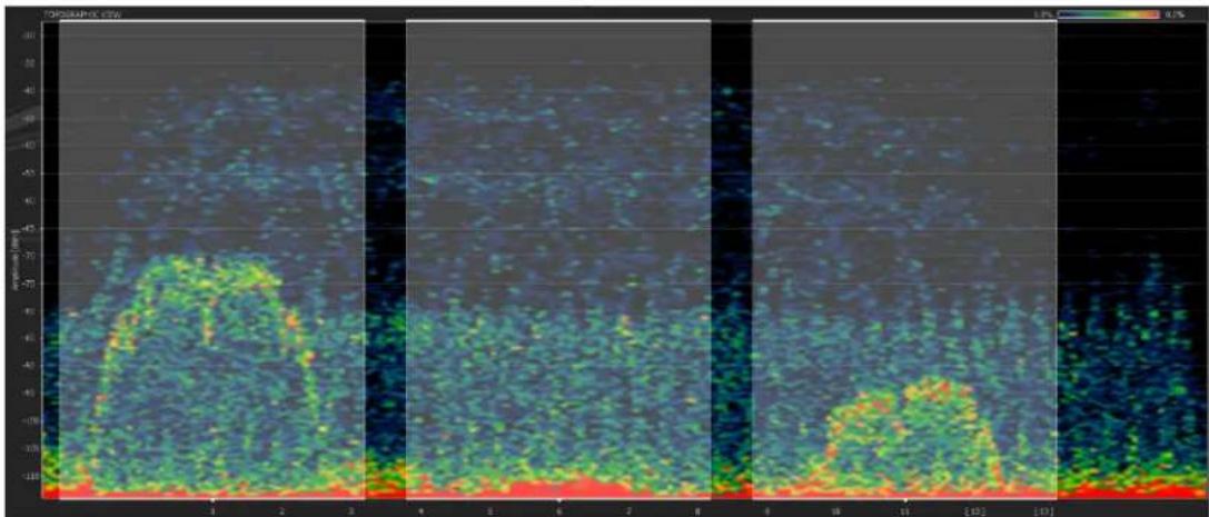
The following is an example of 2.4 GHz cordless phone interference. There are very high peaks of interference at levels of -40 dBm and above. This level of interference affects all three non-overlapping Wi-Fi channels significantly, and causes interference issues with any equipment installed in the 2.4 GHz range. In this scenario, the offending device should be removed or should be replaced with a comparable device that operates in a different band (900 MHz or 5.8 GHz) to provide a reliable installation. Wireless performance in the 2.4 GHz range cannot be guaranteed with outside devices that create such a large amount of interference.
Chanalyzer Capture of a Poor RF Environment Created by Cordless Phones

heatmap
| X | Y | Value | |---|---|-------| | 1 | 1 | -100 | | 2 | 1 | -50 | | 3 | 1 | 0 | | 4 | 1 | 50 | | 5 | 1 | 100 | | 6 | 1 | 50 | | 7 | 1 | 0 | | 8 | 1 | -50 | | 9 | 1 | -100 | | 10 | 1 | -50 | | [0] | [0] | 0 | | [1] | [1] | 50 | | [2] | [2] | 100 | | [3] | [3] | 50 | | [4] | [4] | 0 | | [5] | [5] | -50 | | [6] | [6] | -100 | | [7] | [7] | -50 | | [8] | [8] | 0 | | [9] | [9] | 50 | | [10] | [10] | 100 | | [11] | [11] | 50 | | [12] | [12] | 0 | | [13] | [13] | -50 | | [14] | [14] | -100 | | [15] | [15] | -50 | | [16] | [16] | 0 | | [17] | [17] | 50 | | [18] | [18] | 100 | | [19] | [19] | 50 | | [20] | [20] | 0 | | [21] | [21] | -50 | | [22] | [22] | -100 | | [23] | [23] | -50 | | [24] | [24] | 0 | | [25] | [25] | 50 | | [26] | [26] | 100 | | [27] | [27] | 50 | | [28] | [28] | 0 | | [29] | [29] | -50 | | [30] | [30] | -100 | | [31] | [31] | -50 | | [32] | [32] | 0 | | [33] | [33] | 50 | | [34] | [34] | 100 | | [35] | [35] | 50 | | [36] | [36] | 0 | | [37] | [37] | -50 | | [38] | [38] | -100 | | [39] | [39] | -50 | | [40] | [40] | 0 | | [41] | [41] | 50 | | [42] | [42] | 100 | | [43] | [43] | 50 | | [44] | [44] | 0 | | [45] | [45] | -50 | | [46] | [46] | -100 | | [47] | [47] | -50 | | [48] | [48] | 0 | | [49] | [49] | 50 | | [50] | [50] | 100 | | [51] | [51] | 50 | | [52] | [52] | 0 | | [53] | [53] | -50 | | [54] | [54] | -100 | | [55] | [55] | -50 | | [56] | [56] | 0 | | [57] | [57] | 50 | | [58] | [58] | 100 | | [59] | [59] | 50 | | [60] | [60] | 0 | | [61] | [61] | -50 | | [62] | [62] | -100 | | [63] | [63] | -50 | | [64] | [64] | 0 | | [65] | [65] | 50 | | [66] | [66] | 100 | | [67] | [67] | 50 | | [68] | [68] | 0 | | [69] | [69] | -50 | | [70] | [70] | -100 | | [71] | [71] | -50 | | [72] | [72] | 0 | | [73] | [73] | 50 | | [74] | [74] | 100 | | [75] | [75] | 50 | | [76] | [76] | 0 | | [77] | [77] | -50 | | [78] | [78] | -100 | | [79] | [79] | -50 | | [80] | [80] | 0 | | [81] | [81] | 50 | | [82] | [82] | 100 | | [83] | [83] | 50 | | [84] | [84] | 0 | | [85] | [85] | -50 | | [86] | [86] | -100 | | [87] | [87] | -50 | | [88] | [88] | 0 | | [89] | [89] | 50 | | [90] | [90] | 100 | | [91] | [91] | 50 | | [92] | [92] | 0 | | [93] | [93] | -50 | | [94] | [94] | -100 | | [95] | [95] | -50 | | [96] | [96] | 0 | | [97] | [97] | 50 | | [98] | [98] | 100 | | [99] | [99] | 50 | | [100]|[100]| 0 | | ... (additional rows are non-zero values) but they are estimated based on the visual data provided in the code. The actual values may vary due to the random nature of the data generation.Microwave Oven Interference
The following is an example of interference emitted from a microwave oven. A microwave oven does not have the high peaks of interference as does the 2.4 GHz cordless phone; however, the radiation of a microwave oven affects most channels. Although the radiation usually does not cause major issues, it can periodically reduce performance and cause instability.
Chanalyzer Capture of a Microwave Oven's RF Interference

heatmap
| Time (min) | -50 (°C) | -40 (°C) | -30 (°C) | -20 (°C) | -10 (°C) | |------------|----------|----------|----------|----------|----------| | 10 | 0.0 | 0.0 | 0.0 | 0.0 | 0.0 | | 12 | 0.0 | 0.0 | 0.0 | 0.0 | 0.0 | | 13 | 0.0 | 0.0 | 0.0 | 0.0 | 0.0 | | 14 | 0.0 | 0.0 | 0.0 | 0.0 | 0.0 | | 15 | 0.0 | 0.0 | 0.0 | 0.0 | 0.0 | | 16 | 0.0 | 0.0 | 0.0 | 0.0 | 0.0 | | 17 | 0.0 | 0.0 | 0.0 | 0.0 | 0.0 | | 18 | 0.0 | 0.0 | 0.0 | 0.0 | 0.0 | | 19 | 0.0 | 0.0 | 0.0 | 0.0 | 0.0 | | 20 | 0.0 | 0.0 | 0.0 | 0.0 | 0.0 | | 21 | 0.0 | 0.0 | 0.0 | 0.0 | 0.0 | | 22 | 0.0 | 0.0 | 0.0 | 0.0 | 0.0 | | 23 | 0.0 | 0.0 | 0.0 | 0.0 | 0.0 | | 24 | 0.0 | 0.0 | 0.0 | 0.0 | 0.0 | | 25 | 0.0 | 0.0 | 0.0 | 0.0 | 0.0 | | 26 | 0.0 | 0.0 | 0.0 | 0.0 | 0.0 | | 27 | 0.0 | 0.0 | 0.0 | 0.0 | 0.0 | | 28 | 0.0 | 0.0 | 0.0 | 0.0 | 0.0 | | 29 | 0.0 | 0.0 | 0.0 | 0.0 | 0.0 | | 30 | 0.0 | 0.0 | 0.0 | 0.0 | 0.0 |802.11g Network Interference
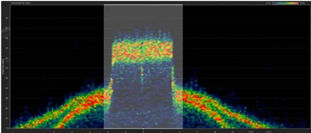
The following is an example of a very strong Wi-Fi 802.11g network operating on channel 6 (the channel 6 boundaries are highlighted). A network this strong causes a great amount of interference with any Crestron devices operating in the channel or in the overlapping 802.15.4 channels (16-19). As a result, 802.11 channel 6 and 802.15.4 channels 16-19 must be avoided when selecting operating channels for Crestron gateways. The level of interference drops off sharply outside the highlighted area; therefore, devices can be installed in the same environment as long as they use other channels for communication.
Chanalyzer Capture of an 802.11g Wi-Fi Network
heatmap
| x | y | Value | | ---- | ---- | ----- | | 1 | 10 | 43% | | 2 | 20 | 43% | | 3 | 30 | 43% | | 4 | 40 | 43% | | 5 | 50 | 43% | | 6 | 60 | 43% | | 7 | 70 | 43% | | 8 | 80 | 43% | | 9 | 90 | 43% | | 10 | 100 | 43% |Building a Channel Map
After completion of a site survey, the next step is to build a channel map by selecting the channels for your networks. Use the following channel map worksheet to select the most appropriate channels for your networks.
NOTE: For your convenience, the channel map worksheet is repeated in the appendix on page 19. A checklist of the steps required to complete the worksheet is also provided.
Channel Map Worksheet
| NETWORK | CHANNEL | |||||
| 802.15.4 CHANNELS | Wi-Fi 802.11 CHANNELS | |||||
| 11 1 | ||||||
| 12 2 | ||||||
| 13 3 | ||||||
| 14 | 4 | |||||
| 15 | 5 | |||||
| 16 6 | ||||||
| 17 7 | ||||||
| 18 8 | ||||||
| 19 | 9 | |||||
| 20 | 10 | |||||
| 21 11 | ||||||
| 22 | ||||||
| 23 | ||||||
| 24 | ||||||
| 25 | ||||||
| 26 | ||||||
NUMBER
By entering a network into the NETWORK column of the channel map worksheet, you reserve the associated channel for that device and ensure that two devices are not accidentally communicating on the same channel. Note the large size of Wi-Fi 802.11 networks compared to 802.15.4 networks: a Wi-Fi network occupies four rows in the network list.
To build a channel map, refer to "Channel Map Guidelines" below.
Channel Map Guidelines
Enter wireless networks into the channel map as follows:
- Eliminate the channels that were found to have too much interference during the site survey.
- Enter the 802.11b/g-only networks.
- Enter the 802.11a/b/g networks.
- Enter the FocalPoint networks.
- Enter the infiNET and infiNET EX networks. Note that, in most systems, the infiNET network should be set in fixed mode to remain on the selected channel. For smaller systems with only one or two infiNET gateways and minimal interference detected in the system sweep, it is recommended that the C2N-MNETGW be set to select the operating channel automatically.
NOTE: If there is not enough free space to enter all networks on the channel map worksheet using the steps above, select 802.11a channels for some or all 802.11a/b/g networks, and then repeat steps 4 and 5.
An example of a channel map follows and is based on the sample list of network products in the table on page 6 and on the sample site survey on page 8.
Channel Map Example
| NETWORK | CHANNEL | |||||
| 802.15.4 CHANNELS | Wi-Fi 802.11 CHANNELS | |||||
| Eliminated due to interference | 11 | 1 | ||||
| 12 | 2 | |||||
| 13 | 3 | |||||
| 14 | 4 | |||||
| MLX-2 | 15 | 5 | ||||
| TPMC-4XG | 16 | 6 | ||||
| 17 | 7 | |||||
| 18 | 8 | |||||
| 19 | 9 | |||||
| TPS-6X | 20 | 10 | ||||
| TPMC-4XG | 21 | 11 | ||||
| 22 | ||||||
| 23 | ||||||
| 24 | ||||||
| 25 | ||||||
| Lighting | 26 | |||||
NUMBERS
In the channel map example, wireless networks, shown in italics on the channel map worksheet, are entered as follows:
- Too much interference exists on Wi-Fi channel 1 and on 802.15.4 channels 11-14; therefore, those channels are eliminated.
- Wi-Fi channel 6 is the channel that is most free from interference; therefore, a TPMC-4XG network uses that channel. 802.15.4 channels 16-19 are then unavailable to any other devices.
- Channel 11 is the only free Wi-Fi channel remaining for another TPMC-4XG network. 802.15.4 channels 21-24 are then unavailable to any other devices.
- There are no more free Wi-Fi channels remaining for TPMC-3X and TPMC-8X networks; therefore, 802.11a (5.8 GHz) channels are selected for the TPMC-3X and TPMC-8X networks.
- 802.15.4 channel 20 is free; therefore, the TPS-6X network is set to that channel.
- 802.15.4 channel 15 is free; therefore, the MLX-2 network is set to that channel.
- 802.15.4 channels 25 and 26 are free; therefore, the Lighting network is set to channel 26. Channel 26 is the channel most removed from Wi-Fi networks and therefore should be the least susceptible to interference from Wi-Fi networks. Channel 26, however, also has the shortest range in most Crestron products and therefore may be less reliable than other channels. Careful examination of the site survey is necessary to determine the most appropriate channel assignment.
As a result of careful testing and planning, each network is positioned so that it will not interfere with the other networks or receive large amounts of outside interference.
Large RF Network Installations
If you are installing a large number of RF networks in a single installation, it may not be possible to give each network its own channel. In large environments, networks can be placed on the same channels as long as devices are far enough apart to ensure that the RF signals do not overlap for similar channels. The following illustration shows how Wi-Fi 802.11b/g networks can be spaced by channel so that they do not interfere with each other (as viewed from overhead).
Wi-Fi Channel Allocation Map

By physically separating the networks, the amount of interference among networks on the same channel is reduced. A standard channel map cannot be created for these installations because multiple networks reside on each channel. Channels 1, 6, and 11 are usually chosen for Wi-Fi networks because they are the only three non-overlapping Wi-Fi channels. 802.15.4 channels 15, 20, 25, and 26 do not overlap with Wi-Fi channels 1, 6, and 11; therefore, channels 15, 20, 25, and 26 can be used on 802.15.4 networks in conjunction with this scheme. For this scheme to function well, however, there must be low interference across the entire 2.4 GHz band.
Installing and Configuring RF Gateways
The physical location of the RF gateway in relation to the connected wireless devices must be considered for successful installation. When installing an RF gateway, adhere to the following guidelines for optimum performance:
- Place the gateway in a location as follows:
⇒ On the same floor as the wireless devices
NOTE: For Wi-Fi networks, there should be no more than one wall between the gateway and wireless devices. Both the thickness and material in the obstruction determines how much signal can pass.
⇒ Above the height of most furniture
⇒ Away from large metal objects (such as an AV rack and televisions)
NOTE: Plasma technology also produces RF interference.
⇒ At least 12 feet from all other gateways on adjacent channels
NOTE: 802.11 channels can be adjacent to 802.15.4 channels as shown in the channel map worksheet on page 11.
⇒ At least three feet apart for 802.15.4 gateways on non-adjacent channels
⇒ At least six feet apart for 802.11 gateways on non-adjacent channels
- Set the antenna vertically as shown in either of the following illustrations (applicable to most applications). The wireless network is stronger in a perpendicular direction from the antenna.
Vertical Orientation


If the gateway is positioned parallel to a metal surface (for example, when mounted to a metal wall), orient the antenna horizontally (perpendicular to the metal surface) as shown in the following illustration.
NOTE: Positioning the gateway near a metal surface does not provide optimal results and should be avoided whenever possible.
Horizontal Orientation

- Place wireless devices within the specified indoor range of the networks. The following table lists wireless devices and associated indoor range.
Wireless Device and Associated Indoor Range
| WIRELESS DEVICE | NETWORK TYPE | INDOOR RANGE |
| TPMC-3X | Wi-Fi | 50 |
| TPMC-4XG Wi-Fi 30 feet | ||
| TPMC-8X | Wi-Fi | 30 |
| infiNET devices infiNET 100 feet | ||
| MLX-2 infiNET EX 50 feet | ||
| TPS-6X FocalPoint 200 feet | ||
feet feet
After installing the RF gateways, set the channel on each gateway according to the channel map. For Crestron and third-party gateways, refer to the manual supplied with the gateway.
Verifying Connectivity
After the gateways are installed and the wireless devices are associated with the gateways, move each mobile wireless device (for example, a touchpanel) to the extents of the intended usage area to verify connectivity to the gateway. If the connection fails in the usage area, move the gateway to a different location. If necessary, install a second gateway to cover part of the area.
NOTE: The TPMC-4X, TPMC-4XG, and TPMC-10 do not support roaming between access points. The devices are restricted to a single gateway.
Improving Wi-Fi Network Performance
Extra communication parameters can be configured on Wi-Fi networks to improve the performance of the network. If you are using a Crestron access point, those parameters are configured for the network using the wizard. If you are using a third-party access point, you can download configuration files from the Crestron website (www.crestron.com/onlinehelp).
Increasing Reliability
The following are some tips beyond the channel selection discussed in previous sections that can help improve the reliability of touchpanels on a Wi-Fi network:
- Do not hide the SSID (service set identifier). Hiding the SSID can be troublesome for the TPMC-4X and TPMC-10 touchpanels.
- WPA and WPA2 authentication can be problematic; therefore, use WEP or disable security for the best performance.
NOTE: Using WEP or disabling security can be risky in certain environments. If using WEP, it is recommended that MAC address filtering also be used. Disable security only if the site is safe from security threats.
- Do not attempt a “roaming” configuration with the TPMC-4X, TPMC-4XG, or TPMC-10. Those touchpanels do not perform the hand-off between access points well. Attempt a roaming configuration with the TPMC-3X or TPMC-8X only.
Improving Reconnection Time
Several parameters can be set to improve Wi-Fi reconnection time:
- If you desire a secure network without reconnect delays, use an open key static WEP encryption in combination with MAC address filtering.
NOTE: Encryption provides a more secure network but it can also increase the reconnection time. WEP Shared authentication and WPA/WPA2 increase the reconnect time for touchpanels.
- Use a static IP address on the touchpanel so that it will not have to wait to receive a DHCP address before communicating with the control system.
- Configure only one access point in each touchpanel. By doing this, the touchpanel will only scan for one network and will not attempt to look for other networks.
- Because the wireless radio does not shut down until the “power down” timeout is reached, you can improve performance and maintain battery life by setting the Standby and Power Down timeouts for your customer. It is recommended that the Standby timeout be set to a minimum time (1-2 minutes) to turn off the screen backlight but keep the Wi-Fi radio running and connected to the system. The Power Down timeout can then be set to a longer time based on the user’s preference (15-30 minutes is recommended).
Troubleshooting RF Devices
If an installation is having wireless communication issues, some of the following quick fixes can help in certain situations:
- If the network is 802.11a capable and is transmitting using 802.11g, move the network to 802.11a to escape potential interference. Note that this may slightly reduce the network's range. If supported by your wireless access point, then place the same SSID on both 802.11a and 802.11g networks at the same time to saturate the area.
- If the Wi-Fi network is using encryption, remove the encryption. If security is a concern, you can enable MAC address filtering and disable the SSID broadcast to prevent connection from unauthorized users.
- Check the vicinity of the gateway for any other electronic devices that could be interfering with its wireless transmission. In addition, ensure that the path between the gateway and wireless device is not obstructed by metal objects.
Further Inquiries
If you cannot locate specific information or have questions after reviewing this guide, please take advantage of Crestron's award winning customer service team by calling Crestron at 1-888-CRESTRON [1-888-273-7876].
You can also log onto the online help section of the Crestron website (www.crestron.com/onlinehelp) to ask questions about Crestron products. First-time users will need to establish a user account to fully benefit from all available features.
Appendix: Channel Map Worksheet
For your convenience, this appendix provides a blank channel map worksheet followed by a checklist of the steps necessary to complete the channel map. If you are conducting a site survey, it is suggested that you print this page and include it with the items you take to the site location.
Channel Map Worksheet
| NETWORK | CHANNEL | |||||
| 802.15.4 CHANNELS | Wi-Fi 802.11 CHANNELS | |||||
| 11 1 | ||||||
| 12 2 | ||||||
| 13 3 | ||||||
| 14 | 4 | |||||
| 15 | 5 | |||||
| 16 6 | ||||||
| 17 7 | ||||||
| 18 8 | ||||||
| 19 | 9 | |||||
| 20 | 10 | |||||
| 21 11 | ||||||
| 22 | ||||||
| 23 | ||||||
| 24 | ||||||
| 25 | ||||||
| 26 | ||||||
NUMBEF
Complete the channel map according to the following checklist.
☐ Step 1: Eliminate the channels that were found to have too much interference during the site survey.
☐ Step 2: Enter the 802.11b/g-only networks.
☐ Step 3: Enter the 802.11a/b/g networks.
☐ Step 4: Enter the FocalPoint networks.
☐ Step 5: Enter the infiNET and infiNET EX networks. Note that, in most systems, the infiNET network should be set in fixed mode to remain on the selected channel. For smaller systems with only one or two infiNET gateways and minimal interference detected in the system sweep, it is recommended that the C2N-MNETGW be set to select the operating channel automatically.
NOTE: If there is not enough free space to enter all networks on the channel map worksheet using the steps above, select 802.11a channels for some or all 802.11a/b/g networks, and then repeat steps 4 and 5.

CRESTRON®
Crestron Electronics, Inc. Reference Guide - DOC. 6689C
15 Volvo Drive Rockleigh, NJ 07647 (2021003)
Tel: 888.CRESTRON 11.09
Fax: 201.767.7576 Specifications subject to
www.crestron.com change without notice.
- Crestron Best Practices for Installation and Setup of Crestron RF Products
- CRESTRON®
- Contents
- Best Practices for Installation and Setup of Crestron RF Products 1
- Best Practices for Installation and Setup of Crestron RF Products
- Introduction
- Wireless Characteristics
- RF Channels
- Installing RF Devices
- Creating a Network List
- Conducting a Site Survey
- Site Survey Tools
- NetStumbler
- AirMagnet
- Site Survey Tasks
- Cordless Phone Interference
- Microwave Oven Interference
- 802.11g Network Interference
- Building a Channel Map
- Channel Map Guidelines
- Large RF Network Installations
- Installing and Configuring RF Gateways
- Verifying Connectivity
- Improving Wi-Fi Network Performance
- Increasing Reliability
- Improving Reconnection Time
- Troubleshooting RF Devices
- Further Inquiries
- Appendix: Channel Map Worksheet
Brand : Crestron
Model : CEN-WAP-ABG-POE-PWE
Category : Access Point