
2178-XL - Uncategorized 3M - Free user manual and instructions
Find the device manual for free 2178-XL 3M in PDF.


| Product Type | Fiber Optic Splice Closure |
| Model | 2178-XL and 2178-XL/FR (Flame Retardant) |
| Brand | 3M |
| Capacity (Single Fusion Splices) | Up to 576 |
| Capacity (Mass Fusion Splices) | Up to 1728 |
| Port Configuration | Two 1.0" and two 1.4" ports per end |
| Kit Contents (Main) | Closure body, strain relief brackets, washer trees, plugs, cable ties, dual lock fasteners, rubber splicing tape, silicone lubricant, hose clamps, sheath scuff, tray support, splice trays, tape collar gauge, K-connectors |
| Flame Retardant Option | Yes (2178-XL/FR) |
| Cable Preparation | Sheath removal, strength member attachment, tape collar build-up |
| Sealing Method | Gasket with silicone lubricant, bolted cover |
| Torque Specification (Cover Bolts) | 240 in-lbs (2178-XL) / 50 in-lbs (2178-XL/FR) |
| Maximum Test Pressure | 10 PSI |
| Compatible Splicing Trays | 3M Splice Tray 2527 (included) |
| Cable Addition Kit | 2181-XL and 2181-XL/FR (optional) |
| Accessories | Ground isolation kit, aerial hanger, wall mount bracket, fanout kit, multi-port grommets, cable fanout kits, shield bond connectors |
| Warranty | 1 year from purchase |
| Applications | Fiber optic splicing for telecommunications, FTTH, and network closures |
Frequently Asked Questions - 2178-XL 3M
User questions about 2178-XL 3M
0 question about this device. Answer the ones you know or ask your own.
Ask a new question about this device
Download the instructions for your Uncategorized in PDF format for free! Find your manual 2178-XL - 3M and take your electronic device back in hand. On this page are published all the documents necessary for the use of your device. 2178-XL by 3M.
USER MANUAL 2178-XL 3M
3M™ Fiber Optic Splice Closure
2178-XL & 2178-XL/FR
3M™ Cable Addition Kit 2181-XL and 2181-XL/FR
Instructions
1.0 Contents
1.0 General....3
2.0 Kit Contents ....3
3.0 Cable Preparation....4
4.0 Drop Cable Preparation....8
5.0 Tray Installation and Splicing....11
6.0 Splice Closure Assembly 12
7.0 3M™ Cable Addition Kit 2181-XL and 2181-XL/FR .....12
8.0 Closure Accessories 13
1.0 General
1.1 The 3M ^™ Fiber Optic Splice Closure 2178-XL and Flame Retardant Splice Closure 2178-XL/FR have been developed to accommodate up to 576 single fusion splices and 1728 mass fusion splices. The closures have two 1.0" ports and two 1.4" ports on each end. New larger trays have been developed, providing more room for ribbon fibers and splices.
2.0 Kit Contents
Visually inspect all components. If any component is missing or appears damaged, do not install. Call customer service at 1-800-426-8688 for a replacement product.
2.1 3M ^™ Fiber Optic Splice Closure 2178-XL and 2178-XL/FR kit contents:
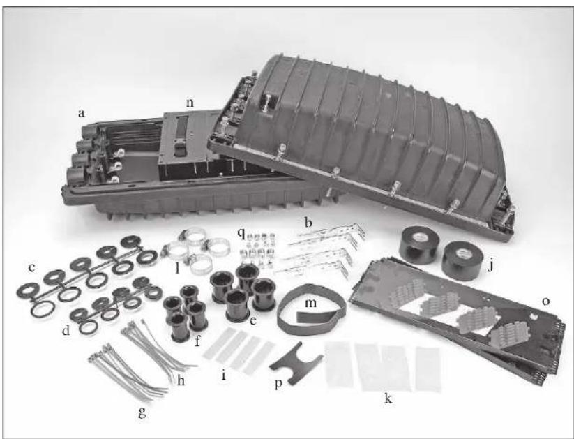
a) 1 - 2178-XL closure body with bolts
b) 4 - Strain relief/strength member brackets
c) 4 - 1.4" washer trees
d) 4 - 1" washer trees
e) 4 - 1.4" plugs
f) 4 - 1" plugs
g) 8 - Cable ties (blue)
h) 8 - Cable ties (green)
i) 4 - 3M ^™ Dual Lock ^™ Fasteners
j) 2 - Rolls Scotch® Linerless Rubber Splicing Tape 130C
k) 4 - Packets of silicone lubricant
1) 4 - 1.5" hose clamps
m) 1 - Sheath scuff
n) 1 - Tray support with straps
o) 2 - 3M ^® Splice Trays 2527 with inserts
p) 1 - Tape collar gauge
q) 8 - K-connectors & screws
2.2 3M ^™ Cable Addition Kit 2181-XL and 2181-XL/FR Kit Contents
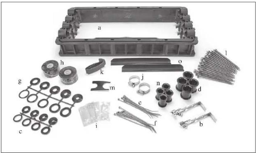
a) 1 - 2181-XL and 2181-XL/FR adapter with gasket
b) 2 - Sheath retention inserts
c) 4 - 1" washer trees
d) 4 - 1.4" plug
e) 8 - Cable ties (blue)
f) 8 - Cable ties (green)
g) 4 - 1.4" washer trees
h) 2 - Roll Scotch® Linerless Rubber Splicing Tape 130C
i) 4 - Packet of silicone lubricant
j) 2 - 1" hose clamps
k) 1 - Sheath scuff
1) 18 - Bolts
m) 1 - Tape collar gauge
n) 4 - 1" plugs
o) Slack storage retainers
2.3 Additional materials required:
For armored sheath cable, use 3M ^™ Scotchlok ^™ Shield Bond Connector 4460-D/DS. To branch splice in unused ports, order 3M ^™ Cable Strain Relief/Strength Member Bracket 2178-XL-XSB-SR-SMC, part no. 80-6113-2343-9.
3.0 Cable Preparation
3.1 Determine amount of cable needed for storage and splicing.
3.2 Remove sheath and clean fiber per company practice.
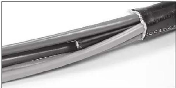
3.3 Scuff 6" of cable sheath, starting at end of sheath.
natural_image
Close-up of a black cable with exposed insulation and insulation sheath, showing internal structure (no text or symbols)Figure 1
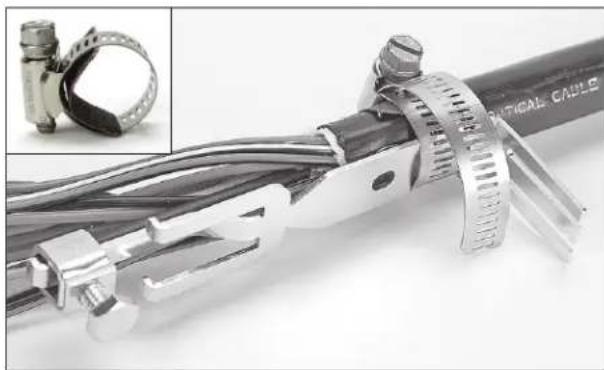
3.4 Cut a small length of the unused sheath scuff and place it grit side inward inside of the hose clamp.
Note: The cut piece of sheath scuff should wrap at least halfway around the cable sheath, but not completely around the cable.
3.4.1 Place cable retention clamp on cable so that hose clamp will be 1" (25 mm) from end of sheath.
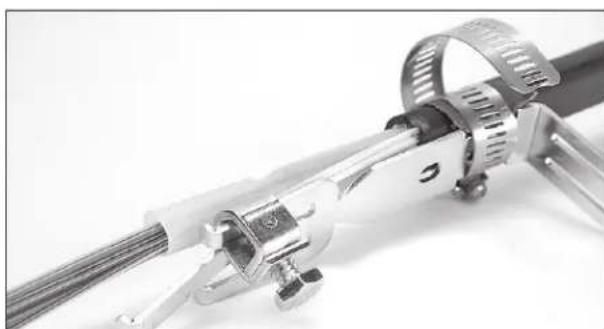
3.4.2 If cable has central strength member, assemble strength member clamp onto strain relief bracket as shown in Figure 2. Mark and cut the central strength member at end of strength member clamp. Slide central strength member under retention lug and tighten bolt to 40 in-lbs ± 5 in-lbs (4.6 N•m ± 0.6 N•m). Install hose clamp and tighten to 40 in-lbs ± 5 in-lbs (4.6 N•m ± 0.6 N•m).
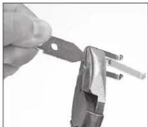
3.4.3 If cable has no central strength member, break off the three prongs using pliers and use only the strain relief bracket as shown in Figure 3.
natural_image
Close-up of a mechanical clamp with metal components and a close-up inset showing a clamp attachment (no visible text or symbols)Figure 2
natural_image
Close-up of a hand using a metal pliers to cut a piece of wire (no text or symbols visible)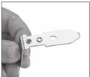
natural_image
Close-up of a hand holding a metal tool with two circular holes (no text or symbols visible)Figure 3
3.4.4 Install hose clamp and tighten.
natural_image
Close-up of a mechanical device with metallic components and a coiled cable (no visible text or symbols)Figure 4
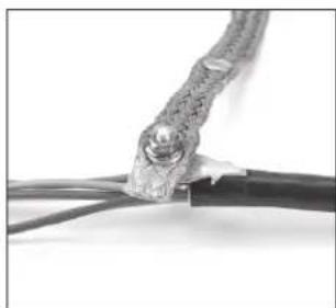
3.4.5 For armored cables (Figure 5), use 3M ^TM Scotchlok ^TM Shield Bond Connector 4460-D or 4460-DS.
natural_image
Close-up of a cable with exposed copper wires and a metallic connector (no text or symbols visible)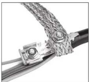
natural_image
Close-up of a twisted cable with metal clamps and braided ends (no text or symbols visible)Figure 5
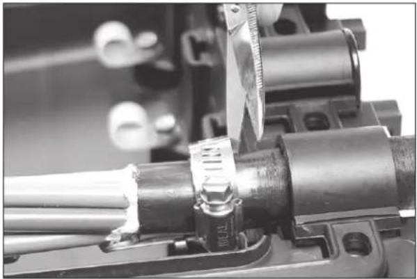
3.5 Place retention clamp into place in the closure and mark location of gasket edges on cable. This will be the area of the tape collar, as shown in Figure 6.
3.6 Determine the diameter of the scuffed area of the cable and choose two (2) appropriately sized washers for each cable. Washer inner diameters should be as close to the diameter of the cable as possible. Washers may be split and placed onto cable.
3.6.1 If diameter of cable is close to either end of the marked washer diameter range try both sizes and choose the snuggest fit available.
For example, if cable diameter measures 1.12," try both the 1.0-1.1 and 1.1-1.2 marked washers. Select the washer with the snuggest fit around the cable diameter, allowing the washer to close at the split.
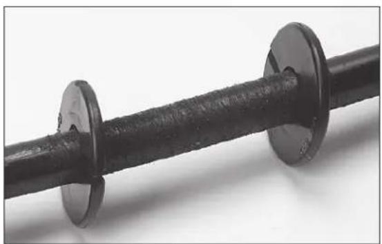
3.7 Split washers and place onto cable on either side of the area marked for tape collar build up, as shown in Figure 7.
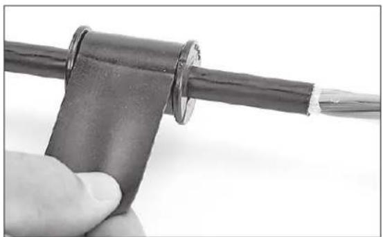
3.8 Using the supplied Scotch ^ Linerless Rubber Splicing Tape 130C, build up the collars to the appropriate diameter.
3.8.1 Stretch tape slightly to fit between marked collar area as best as possible.
natural_image
Close-up of a mechanical assembly with metal components and a measuring tool (no visible text or symbols)Figure 6
natural_image
Close-up of a black cylindrical pipe fitting with flanged ends, no visible text or symbolsFigure 7
natural_image
Close-up of a hand holding a black cable with a metallic ring attached, against a white background (no text or symbols visible)Figure 8
3.8.2 Collars should be built up to 1.45" diameter for large port and 1.05" diameter for the smaller port. Use the tape collar gauge provided in kit to measure for required diameter.
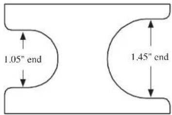
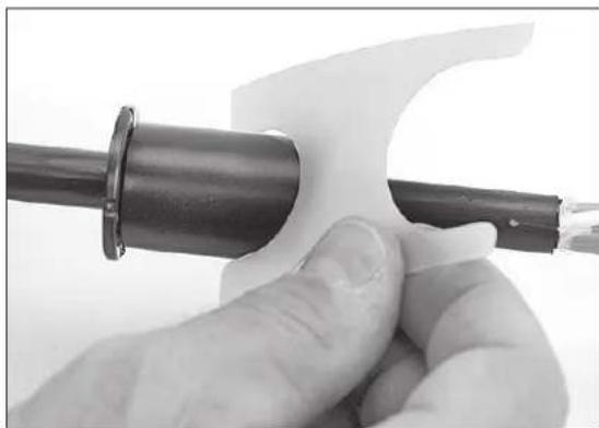
3.9 Coat tape collar with silicone lubricant and insert into gasket at the proper port. Insert cable retention clamp into slot at same time and push down until cable is in proper alignment.
Note: Insure that washers are properly seated in the grooves of the case on either side of the gasket.
Note: Carefully follow health and safety environmental instructions as given on Material Safety Data Sheet for the silicone lubricant.
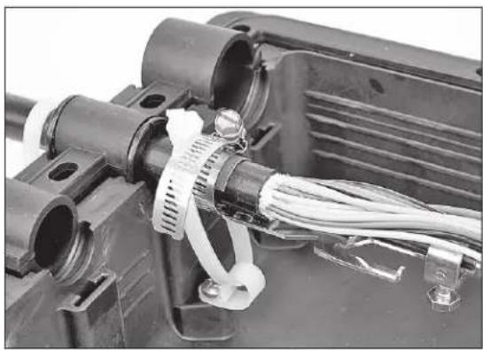
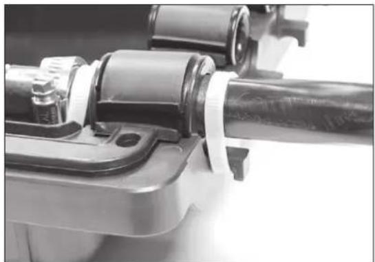
3.10 Using two (2) black cable ties, retain cables in ports by placing ties both inside and outside the base as shown in Figure 11 and 12. (White cable ties used for picture clarity only.)
natural_image
Close-up of a hand holding a black pipe fitting with a white plastic clip, no visible text or symbolsFigure 9
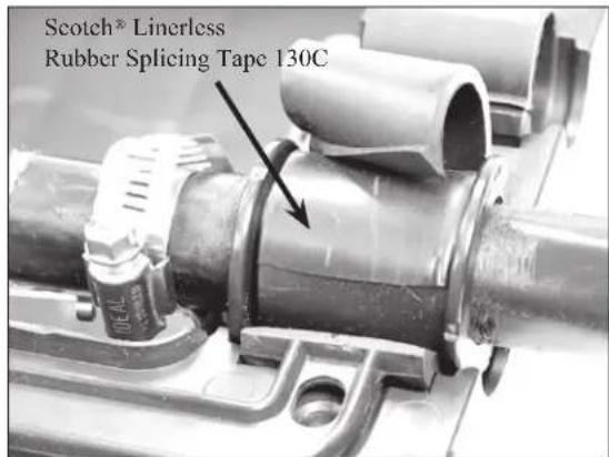
Figure 10
natural_image
Close-up of an electric motor with visible wiring and cooling fins (no text or symbols)Figure 11
natural_image
Close-up of a mechanical assembly with a cylindrical component and clamped parts (no visible text or symbols)Figure 12
4.0 Drop Cable Preparation
4.1 Determine how many drop cables will be passing through 3M™ Multiport Grommet.
4.2 Remove sheath on drops exposing buffer tubes to a length required per company practice.
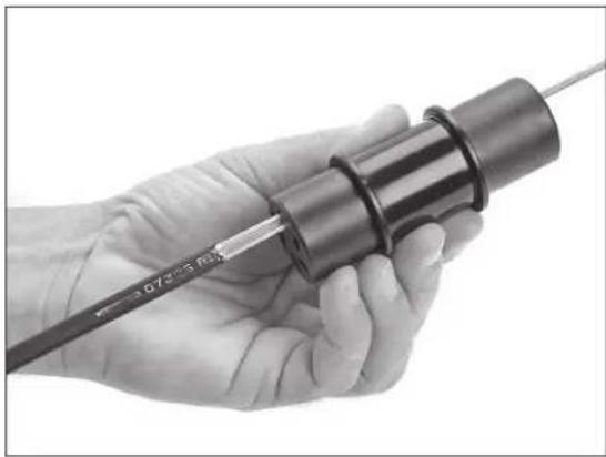
4.3 Insert drops into multiport grommet first and then insert blank plugs last.
Note: A small amount of lubricant provided in kit may be placed on blank plugs and cable to allow for ease of installation into multiport grommet.
An additional method to ease installation is to take sheath scuff supplied in closure kits, and slightly sand the leading edge of the drop cable and blank plugs.
4.4 Grease approximately 2" of cable drop jacket.
4.5 Insert drop 1"-2" into multiport grommet and then pull back out.
4.6 Insert drop the entire length of multiport grommet.
4.7 Repeat steps 4.3–4.6 for the blank plugs as well.
Note: Leave future ports orientated to top of closure for ease of future installations of drop.
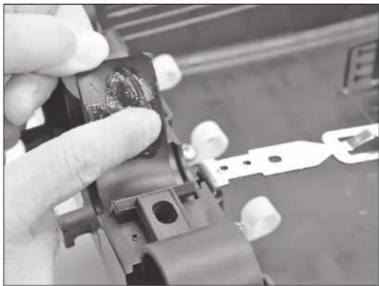
4.8 Place a small amount of lubricant on the gasket inside diameter in the area where it seals with multiport grommet.
Note: Carefully follow health and safety environmental instructions as given on Material Safety Data Sheet for the silicone lubricant.
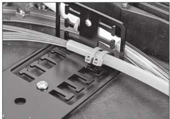
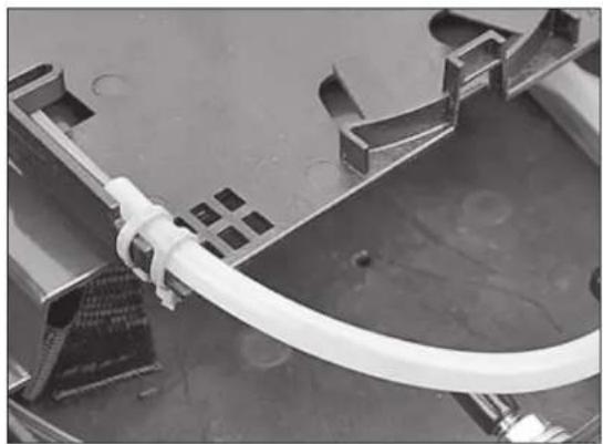
4.9 For ribbon transition to tray applications, secure the transition tube to the bracket mounted in base.
natural_image
Close-up of a hand holding a cylindrical mechanical component with a pen inserted (no visible text or symbols)Figure 13
natural_image
Close-up of a gloved hand holding a small electronic component with a tool, no visible text or symbolsFigure 14
natural_image
Close-up of a mechanical assembly with coiled white cables and mounting brackets (no visible text or symbols)Figure 15
4.10 When tray support and tray are in place, mount the other end of the transition tube to the tray.
natural_image
Close-up of a white cable with a grid-patterned component attached to a metal frame (no visible text or symbols)Figure 16
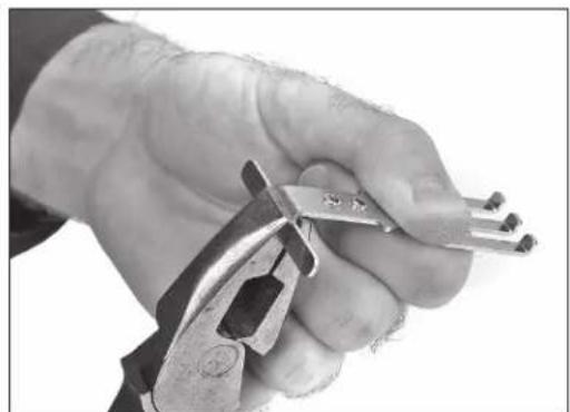
4.11 Break off the tab feature as shown on both cable strain relief brackets.
natural_image
Close-up of a hand using pliers to cut metal parts (no text or symbols visible)Figure 17
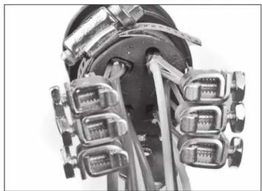
4.12 Place cable strain relief brackets on either side of the grommet, with three drops on either side as shown. Insert cable strength members into small K-connectors.
natural_image
Close-up of a mechanical device with metallic components and a central shaft (no visible text or symbols)Figure 18
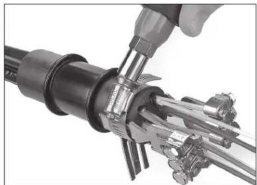
4.13 Secure cable strain relief brackets and the strain relief bracket from the closure to the grommet with the hose clamp as shown. Tighten the hose clamp to 40 in.-lbs. ± 5 in.-lbs. (4.6 N•m ± 0.6 N•m).
Note: Ensure that extruded retention feature of strain relief has sufficient contact with surface of grommet.
natural_image
Close-up of a hand using a tool to adjust or install a mechanical component, no visible text or symbols.Figure 19
4.14 Tighten the six K-connector nuts to 40 in.-lbs. ± 5 in.-lbs. (4.6 N•m ± 0.6 N•m) each.
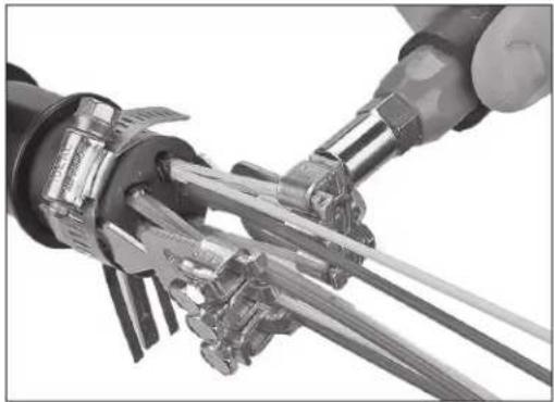
natural_image
Close-up of a robotic arm connecting mechanical components with a tool (no visible text or symbols)Figure 20
4.15 Place cable strain relief and 3M ^™ Multiport Grommet assembly into closure.
4.16 Place cable ties around multiport grommet assembly inside and out as shown in Figure 21.
Note: White cable ties are shown for clarity.
4.17 Follow closure instruction for all other preparation leading up to and including sealing closure.
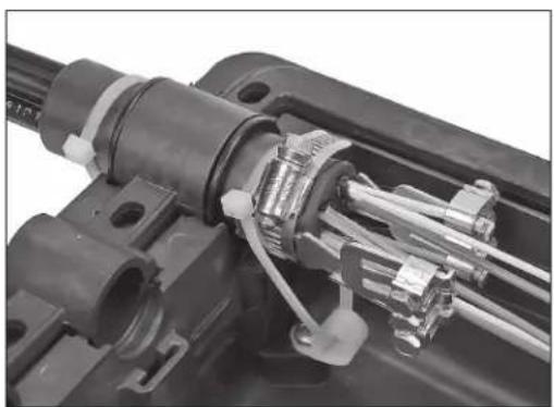
natural_image
Close-up of mechanical components with visible springs and connectors (no text or symbols)Figure 21
5.0 Tray Installation and Splicing
5.1 Once cables have been anchored, place tray support in position and tighten two (2) screws.
5.2 Remove liner. Place two pieces of 3M™ Dual Lock™ Fastener on tray support, as shown. Mate second two pieces of fastener to the attached pieces. Remove liner from back of top pieces and attach first tray. (See Figure 22)
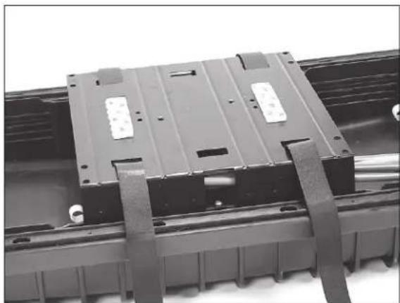
natural_image
Close-up of a black plastic electronic component with metal brackets and mounting holes (no visible text or symbols)Figure 22
5.3 Route the fibers into the tray. Secure buffer tube with cable tie. (See Figure 23)
5.4 Splice per company practice.
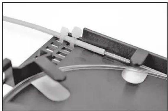
natural_image
Close-up of a mechanical component with clamps and a curved surface (no visible text or symbols)Figure 23
6.0 Splice Closure Assembly
6.1 Coat all gasket surfaces with a light application of silicone lubricant to aid in gasket sealing.
Note: Carefully follow health and safety environmental instructions as given on Material Safety Data Sheet for the silicone lubricant.
6.2 Place cover on base and hand start all bolts. Using tightening sequence (Figure 28), torque all bolts to 240 in-lbs. Torque -FR Closures to 50 in./lbs.
6.3 Closure may be flash tested by pressurizing closure to a maximum of 10 PSI. Check for leaks and then release air pressure.
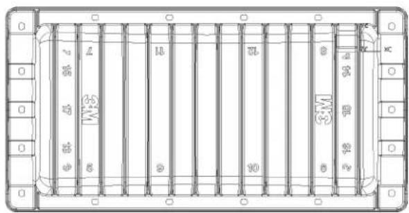
Figure 24
7.0 3M ^TM Cable Addition Kit 2181-XL/XLFR
7.1 Follow steps 3.0–4.0 to prepare cables.
7.2 The tray support can be installed in either the 3M ^™ Fiber Optic Splice Closure 2178-XL or 2178-XL/FR or the 2181 adapter. Install the tray support onto the desired level by placing it into the slots on the closure base or adapter and tightening the screws until snug.
7.3 Install the 2181 adapter between the halves of the 2178 closure using the longer bolts included with the adapter. Follow step 6.0 for assembly.
8.0 Closure Accessories
natural_image
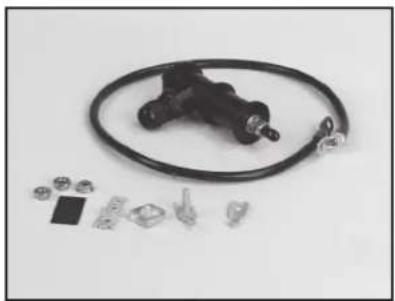
Product photo of a black mechanical valve with coiled tubing and various small components (no visible text or symbols)3M™ External Ground Isolation Kit 2178-EGI
natural_image
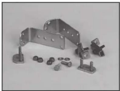
Collection of metal bracket components and bolts on a plain background (no text or symbols visible)3M™ Universal Aerial Hanger Kit 2183-UHB
natural_image
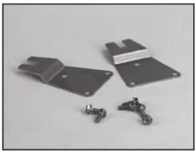
Exterior view of two metal bracket components with metal hardware and mounting brackets (no text or symbols visible)3M™ Wall Mount Bracket 2198
natural_image
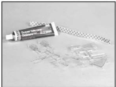
Close-up of a Super Silicone Soldering tool and plastic components on a plain surface (no text or symbols visible)3M™ Cable Fanout Kit 2519 and 2519-X
natural_image
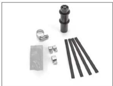
Collection of mechanical components including a cylindrical component, bracket, and multiple parallel rods (no text or symbols visible)3M™ 4-Port Grommet 2178-4PGA
natural_image
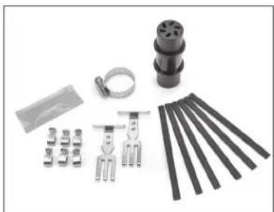
Collection of mechanical clamping tools and components laid out on a white surface (no text or symbols visible)3M™ 6-Port Grommet 2178-6PGA
natural_image
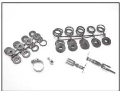
Collection of mechanical parts including rings, clips, and tools (no visible text or symbols)3M™ Cable Branch Port Kit 2178-XL-XSB 3M
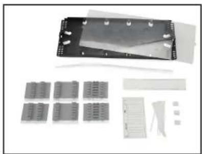
natural_image
Disassembled electronic component with multiple connectors and housing (no visible text or symbols)™ Fiber Optic Splice Tray 2543 3M
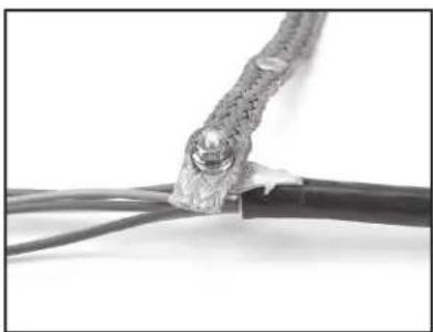
natural_image
Close-up of a damaged cable with exposed metal clamps and insulation (no text or symbols visible)™ Scotchlok™ Shield Bond Connector Assembly 4460-D/FO
3M, Dual Lock and Scotchlok are trademarks of 3M Company. Scotch is a registered trademark of 3M Company.
Important Notice
All statements, technical information, and recommendations related to 3M's products are based on information believed to be reliable, but the accuracy or completeness is not guaranteed. Before using this product, you must evaluate it and determine if it is suitable for your intended application. You assume all risks and liability associated with such use. Any statements related to the product which are not contained in 3M's current publications, or any contrary statements contained on your purchase order shall have no force or effect unless expressly agreed upon, in writing, by an authorized officer of 3M.
Warranty; Limited Remedy; Limited Liability.
This product will be free from defects in material and manufacture for a period of one (1) year from the time of purchase. 3M MAKES NO OTHER WARRANTIES INCLUDING, BUT NOT LIMITED TO, ANY IMPLIED WARRANTY OF MERCHANTABILITY OR FITNESS FOR A PARTICULAR PURPOSE. If this product is defective within the warranty period stated above, your exclusive remedy shall be, at 3M's option, to replace or repair the 3M product or refund the purchase price of the 3M product. Except where prohibited by law, 3M will not be liable for any indirect, special, incidental or consequential loss or damage arising from this 3M product, regardless of the legal theory asserted.
3M
Communication Markets Division
6801 River Place Blvd.
Austin, TX 78726-9000
1-800-426-8688
www.3MTelecommunications.com
Please Recycle. Printed in USA.
© 3M 2010. All Rights Reserved.
78-8130-5055-2-L
- Contents
- General
- Kit Contents
- 3M ™ Cable Addition Kit 2181-XL and 2181-XL/FR Kit Contents
- Cable Preparation
- Drop Cable Preparation
- Tray Installation and Splicing
- Splice Closure Assembly
- 3M TM Cable Addition Kit 2181-XL/XLFR
- Closure Accessories
- Important Notice
- Warranty; Limited Remedy; Limited Liability.
- 3M
- Communication Markets Division
Brand : 3M
Model : 2178-XL
Category : Uncategorized