OnCell G3110-HSDPA - Modem/Router Moxa - Free user manual and instructions
Find the device manual for free OnCell G3110-HSDPA Moxa in PDF.

| Product Type | Industrial Cellular Router / Modem |
| Model | OnCell G3110-HSDPA |
| Brand | Moxa |
| Cellular Technology | HSDPA (3.5G) with backward compatibility to UMTS/EDGE/GPRS |
| Ethernet Ports | 1 x 10/100 Mbps (RJ45) |
| Serial Ports | 1 x RS-232 (DB9 male) |
| Dimensions (W x H x D) | 100 x 70 x 30 mm |
| Weight | 200 g |
| Power Supply | 12–48 VDC (terminal block) |
| Power Consumption | 6 W (typical) |
| SIM Card Slot | 1 x standard SIM (3V/1.8V) |
| Antenna Connector | 1 x SMA female (cellular) |
| Firewall & Security | NAT, port forwarding, VPN pass-through, MAC filter |
| Management | Web GUI, Telnet, SNMP v1/v2c/v3 |
| Operational Temperature | -20°C to 60°C |
| Humidity | 5% to 95% (non-condensing) |
| Mounting | DIN rail or wall mount |
| Cleaning | Wipe with a dry, soft cloth |
| Safety Precautions | Use only supplied power adapter; avoid liquids and extreme temperatures |
| Spare Parts / Repairability | Not user-serviceable; contact Moxa support for repairs |
| General Information | Industrial-grade router for remote monitoring and control applications |
Frequently Asked Questions - OnCell G3110-HSDPA Moxa
User questions about OnCell G3110-HSDPA Moxa
0 question about this device. Answer the ones you know or ask your own.
Ask a new question about this device
Download the instructions for your Modem/Router in PDF format for free! Find your manual OnCell G3110-HSDPA - Moxa and take your electronic device back in hand. On this page are published all the documents necessary for the use of your device. OnCell G3110-HSDPA by Moxa.
USER MANUAL OnCell G3110-HSDPA Moxa
Second Edition, September 2008
1. Overview
There are currently four models in the OnCell G3100 series of IP-modems: the OnCell G3110, OnCell G3150, OnCell G3110-HSDPA, and OnCell G3150-HSDPA. The main difference between the models is the serial interface type. The OnCell G3100 industrial RS-232, RS-232/422/485 GSM/GPRS/LDGE, or UMTS/HSDPA IP modems are some of the most affordable, secure, and versatile products available in the cellular networking market today. These modems also provide remote access and TCP/IP support, and can be configured over a network.
2. Package Checklist
Before Installing the OnCell G3100 IP modem, verify that the package contains the following items:
Standard Accessories
• Document & Software CD
- Omni 1 dBi rubber SMA antenna (OnCell G3100 model name: ANT-CQB-O-1; OnCell G3100-HSDPA model name: ANT-WCDMA-O-1.5 BK)
- Din-Rail Kit
- 5-pin terminal block (screw type)
• 10-pin terminal block (screw type)
• Product warranty statement
- Quick Installation Guide
Optional Accessories
• Power Adaptor: 1.2 A (or above) @ 12V
• DC power supply
• Power jack to terminal block cable
- Quad-band GSM/GPRS/EDGE antennas for OnCell G3110/G3150 series (impedance = 50 ohms):
ANT-CQB-O-0-3m: Omni 1dBi/10cm, magnetic SMA antenna, 3 m ANT-CQB-O-3-3m: Omni 3dBi/25cm, magnetic SMA antenna, 3 m ANT-CQB-O-5-3m: Omni 5dBi/37cm, magnetic SMA antenna, 3 m
Note: Please notify your sales representative if any of the above items are missing or damaged.
P/N: 1802031000011
-1--2--3-
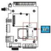
3. Hardware Introduction
Front View
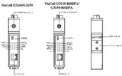
OnCell G3110-HSDPA/
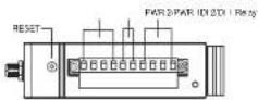
Top View
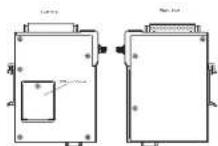
Bottom Views
Side Views
Reset Button—Press the Rest button continuously for 5 sec to load factory defaults: Use a pointed object, such as a straightened paper clip or toothpick, to press the reset button. This will cause the Ready LED to blink on and off. The factory defaults will be loaded once the Ready LED stops blinking (after about 5 seconds). At this point, you should release the reset button (the default IP is 192.168.127.254).
Rear
LED Indicators
The LED indicators on the front panel of the OnCell G3100 are described in the following table.
| LED Name | LED Color | LED Function |
| Power | Green DC Power is active | |
| Off Power is off. or power error condition exists. | ||
| Data | Green Serial Tx | |
| Amher Serial Rx | ||
| Off Ethernet cable is disconnected. | ||
| GSM | Amher GSM is connected. | |
| Off GSM is disconnected. | ||
| GRPS | Amber GPRS is connected. | |
| Off GPRS is disconnected. | ||
| UMTS | Amber UMTS is connected.(OnCell G3100-IISDPA only) | |
| Off UMTS is disconnected.(OnCell G3100-IISDPA only) | ||
| IISDPA | Amber HSDPA is connected.(OnCell G3100-IISDPA only) | |
| off HSDPA is disconnected.(OnCell G3100-IISDPA only) | ||
| Ready | Green Steady on: Software Ready.Blinking slowly (1 sec): The OnCell has been located by the OnCell Search Utility. | |
| Off Power is off, or is booting up. | ||
| Fault | Red Steady on: Booting up, or IP fault.Blinking slowly (1 sec): Cannot get an IP address from the DHCP server | |
| Off Power is off, or there is no error condition. | ||
| Signal(3 LEDs) | Green Number of lit LEDs indicates signal level(at least 2 LEDs must illuminated for data transmission) | |
Digital Input and Output
Six terminals on the terminal block are reserved for the I/O ports, with 2 terminals used for each input, and 2 terminals used for each output.
Digital Input—Digital ON and OFF determine which power input is used: DIN OFF: 0 to 3.3 VDC DIN ON: 10 to 48 VDC (DI COM to DI)
Digital Output - The default for the relay output (DOUT) is open, indicating a normal condition. If the relay output (DOUT) is shorted, it indicates an exception.
Adjustable pull high/low resistor for RS-485 Port
DIP switches on the bottom of the OnCell G3100 are used to set the pull high/low resistor value for each serial port.
| SW | 1 | 2 | |
| Pull High Pull Low Terminator | |||
| ON | 1 KΩ | 1 KΩ | 120 KΩ |
| OFF | 150 KΩ | 150 KΩ | --- |
4. Hardware Installation Procedure
STEP 1: Open the SIM cover, and insert the SIM card in the SIM card slot.
STEP 2: Connect the 12-48 VDC power adaptor to the OnCell G3100 and then plug the power adaptor into a DC outlet.
STEP 3: To configure the OnCell, use an Ethernet cable to connect the OnCell directly to your computer's Ethernet interface.
STEP 4: Connect the OnCell G3100's serial port to a serial device.
5. Software Installation Information
The Document & Software CD contains the User's Manual, OnCell Search Utility, and OnCell Driver Manager. Insert the CD and follow the on-screen instructions. Please refer to the User's Manual for additional details on using the OnCell Search and Driver Manager.
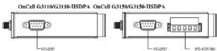
6. Pin Assignments and Cable Wiring
DB9 Male Port Pinouts
Note that the OnCell G3110 only supports RS-232. The RS-422/485 pin assignments only apply to the OnCell G3150.
DB9 Male
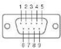
| Pin | RS-232 |
| 1 | DCD |
| 2 | RxD |
| 3 | TxD |
| 4 | DTR |
| 5 | GND |
| 6 | DSR |
| 7 | RTS |
| 8 | CTS |
| 9 | --- |
4W/2W RS-485/RS-422 (Terminal Block) Pinouts
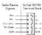
| Pin | RS-422/485 4-wire | RS-485 2-wire |
| 1 | TxD+(B) | -- |
| 2 | TxD-(A) | -- |
| 3 | RxD+(B) | Data+(B) |
| 4 | RxD-(A) | Data-(A) |
| 5 | GND | GND |
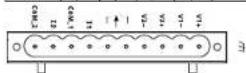
Power Input and Relay Output Pinouts
| PIN | 1 | 2 | 3 | 4 | 5 | 6 | 7 | 8 | 9 | 10 |
| Name | V1+ | V1 | V2+ | V2 | I1 | COM_1 | I2 | COM_2 | ||
| Function | DCPowerinput 1 | DCPowerinput 1 | DCPowerinput 2 | DCPowerinput 2 | RelayOut | RelayOut | DigitalInput | DigitalInputGND | DigitalInputGND | DigitalInputGND |
7. Specifications
LAN Interface
Ethernet 10/100 Mbps, RJ45 connector
Protection Built-in 1.5 KV magnetic isolation
Cellular Interface (for OnCell G3110 & G3150)
Standard Compliance GSM/GPRS/EDGE
Band Selection Quad-band 850/900 MHz. and 1800/1900 MHz
Tx Power I wall GSM 1800/1900, 2 wall EGSM 850/900
GPRS Multi-slot class Class 12
GPRS Terminal Device Class B
GPRS Coding Schemes CS1 to CS4
SIM Control 3V
Cellular Interface (for OnCell G3110-HSDPA & G3150-HSDPA)
Standard Compliance UMTS/HSDPA
Band Selection Tri-band 850/1900/2100 MHz Quad-band
850/900/1800/1900MHz
| Tx Power | 1 watt GSM1800, 2 watt GSM900,0.25 watt UMTS/HSDPA,0.5 watt EDGE900, 0.4 watt EDGE1800 |
GPRS Multi-slot class Class 10
GPRS Terminal Device Class B
GPRS Coding Schemes CS1 to CS4
SIM Control 3V
Serial Interface
No. of Ports 1
Serial Standards G3100: RS-232 (DB9 male connector)
G3150: RS-232 (DB9 male connector),
RS-422/485 (5-pin terminal block connector)
Serial Communication Parameters
Parity None, Even, Odd, Space, Mark
Data Bits 5.6.7.8
Stop Bit(s) 1.1.5.2 (when parity = None)
Flow Control RTS/CTS, XON/XOFF
Speed 50 bps to 921.6 Kbps
I/O Interface
Alarm Contact I relay output with current carrying capacity of IA@24 VDC
Digital Input 2 inputs electrically isolated from the electronics
Power Requirements
Input Voltage 12 to 48 VDC
Data Link 585 to 900 mA (peak) @ 12 V
Environmental Limits
Operating temperature -30 to 55°C (-22 to 131°F), 5 to 95% RH
Storage temperature -40 to 75°C (-40 to 167°F)
Regulatory Approvals
EMC CE Class A, FCC Class A, UL
Warranty
Warranty Period 5 years
Copyright © 2008
Moxa Inc
All rights reserved.
Reproduction without permission is prohibited.

Tel: +886-2-8919-1230 www.moxa.com
Fax: +886-2-8919-1231 support@moxa.com