
MINI AS400 - Inverter PowerPlus - Free user manual and instructions
Find the device manual for free MINI AS400 PowerPlus in PDF.


| Product Type | UPS / Inverter |
| Model | MINI AS400 |
| Brand | PowerPlus |
| Power Rating | 400 VA / 240 W |
| Input Voltage | 220-240 V AC |
| Output Voltage | 220-240 V AC (regulated) |
| Frequency | 50/60 Hz |
| Waveform | Simulated sine wave |
| Battery Type | Sealed lead-acid (maintenance-free) |
| Battery Capacity | 12 V / 7 Ah |
| Typical Backup Time | 10-15 minutes at full load |
| Recharge Time | 4-6 hours to 90% |
| Outlets | 2 x Schuko outlets (or local standard) |
| Protection Features | Overload, short circuit, battery deep discharge, surge protection |
| Dimensions (W x D x H) | 280 x 140 x 86 mm |
| Weight | 4.5 kg |
| Operating Temperature | 0°C to 40°C |
| Noise Level | <40 dB |
| Certifications | CE, RoHS |
| Warranty | 2 years |
| Manual Languages | EN (English) available for download |
Frequently Asked Questions - MINI AS400 PowerPlus
User questions about MINI AS400 PowerPlus
0 question about this device. Answer the ones you know or ask your own.
Ask a new question about this device
Download the instructions for your Inverter in PDF format for free! Find your manual MINI AS400 - PowerPlus and take your electronic device back in hand. On this page are published all the documents necessary for the use of your device. MINI AS400 by PowerPlus.
USER MANUAL MINI AS400 PowerPlus
PRODUCT INTRODUCTION

natural_image
Electronic component with integrated circuit board (no visible text or symbols)
natural_image
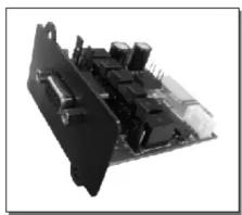
Close-up of a computer motherboard with visible circuitry and connectors (no text or symbols)AS400 card provides dry-contact signals to indicate the run states of UPS. And it can be inserted into the Intelligent Slot directly. The installation is simple and convenient.
APPLICATION TYPES OF UPS

▶ UPS with short Intelligent Slot produced by our company
INSTALLATION

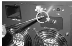
Remove the cover of Intelligent Slot on the rear panel

natural_image
Close-up of a server rack with attached cable connectors and a circular component (no visible text or symbols)1
Insert the Card into the Intelligent Slot.

natural_image
Close-up of a hand inserting a USB into a device (no visible text or symbols)Cover of AS400 Card should be attached close to the rear panel. Then fix it by using screws.
natural_image
Close-up of electronic equipment with a circular component and fan-like components (no visible text or symbols)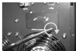
natural_image
Close-up of an electronic device with a highlighted internal component and fan wiring (no readable text or symbols)Use the 9 pin communication cable to connect the UPS and equipment to implement the remote monitor and control.
Note: AS400 Card only provides dry-contact interface and user should exploit monitor and control software by itself.
DIMENSION

60.0mm*75.5mm*17.0mm
2
SPECIFICATION

Electric Parameter of DB-9 Port
| Parameter | SYMBOL | MAX. | UNIT | |
| Diode | Reverse Voltage | V_R | 6 | V |
| Forward Current | I_F | 80 | mA | |
| Peak Forward Current | I_F(jpeak) | 1 | A | |
| Relay | DC Voltage | V_DC | 24 | V |
| DC Current | I_DC | 1.0 | A | |
▶ Pin Definition
| Pin | Pin Name | Reasons | I/O | JP Pin |
| Pin1 | UPS Fault | One or some types of Ups fault occurred. | O/P | NO:JP3 2-1NC: JP3 2-3 |
| Pin2 | Summary Alarm | Summary Alarm One or some following occurred: fault, warning, bypass active, Utility Failure, loss communication | O/P | NC: JP4 2-1NO:JP4 2-3 |
| Pin3 | GND | Common for Pin4 | I/P | |
| Pin4 | Shutdown/ Self-test | If the ups received 3~10s shutdown signal working on battery, it will shutdown itself after 12 Seconds delay. | I/P | Self -Test : Jp8 2-1 |
| Pin5 | Common | Common for Relays | I/P | |
| Pin6 | Bypass Active | The UPS has a failure (or is being serviced) and power is being provided to the system from the utility power line. If utility power fails, the system will lose power. | O/P | NO:JP2 2-1NC: JP2 2-3 |
| Pin7 | Battery Low | The battery source for the UPS is below the predetermined energy level. If the energy level continues to decrease, the UPS may not be able to supply energy to the system. | O/P | NO:JP1 2-1NC: JP1 2-3 |
| Pin8 | UPS On | The UPS is powered on and is capable of providing power to the system (whether utility power is available or not). | O/P | NO:JP6 2-1NC: JP6 2-3 |
| Pin9 | Utility Failure | A failure in utility power to the UPS has occurred. The UPS is providing power to the system. | O/P | NO:JP5 2-1NC: JP5 2-3 |
APPLICATION

Below shows the circuit of basic application to implement the remote monitor and control

flowchart
graph LR
    A["12V"] --> B["UPS FALL"]
    A --> C["SUMMARY ALARM"]
    A --> D["GND"]
    A --> E["SHUTDOWN/UPS TEST"]
    A --> F["COMMON"]
    B --> G["1"]
    C --> H["6"]
    D --> I["7"]
    E --> J["3"]
    F --> K["4"]
    G --> L["BYPASS"]
    H --> M["BATTERY LOW"]
    I --> N["UPS ON"]
    J --> O["LINE LOSS"]
    K --> P["12V"]
user interface
By providing the COMMON with Power below 24V and connecting indicator light and switch button to the interface, the user can monitor the running state of the UPS and can remote shutdown the UPS or do UPS Self-test.
PowerWalker
User Manual
AS400 MINI Card
Brand : PowerPlus
Model : MINI AS400
Category : Inverter