CE2N-416 - Security Camera FRACARRO - Free user manual and instructions
Find the device manual for free CE2N-416 FRACARRO in PDF.

| Product Type | Security Camera |
| Brand | Fracarro |
| Model | CE2N-416 |
| Image Sensor | 1/3" CMOS |
| Resolution | 1920 x 1080 (Full HD) |
| Lens Type | Fixed focal length, 3.6mm |
| Night Vision | Infrared LEDs up to 20m |
| Field of View | 80° horizontal |
| Power Supply | 12V DC, 1A (adapter included) |
| Power Consumption | Max 6W |
| Video Output | CVBS (BNC) / AHD (switchable) |
| Protection Rating | IP66 (weatherproof) |
| Material | Aluminum alloy housing |
| Dimensions | 180 x 70 x 70 mm (without bracket) |
| Weight | Approx. 400 g (camera only) |
| Operating Temperature | -20°C to +50°C |
| Mount Type | Wall or ceiling mount (bracket included) |
| Main Functions | Motion detection, privacy masking, OSD menu |
| Cleaning | Use a soft, dry cloth; avoid solvents |
| Maintenance | Check connections and lens cleanliness periodically |
| Safety | Use only supplied power adapter; keep away from heat sources |
| Spare Parts | Power adapter, mounting kit available from Fracarro |
| Reparability | Contact authorized service center for repairs |
| General Information | Compatible with DVRs supporting AHD/CVBS |
Frequently Asked Questions - CE2N-416 FRACARRO
User questions about CE2N-416 FRACARRO
0 question about this device. Answer the ones you know or ask your own.
Ask a new question about this device
Download the instructions for your Security Camera in PDF format for free! Find your manual CE2N-416 - FRACARRO and take your electronic device back in hand. On this page are published all the documents necessary for the use of your device. CE2N-416 by FRACARRO.
USER MANUAL CE2N-416 FRACARRO
Installer and user Programming Manual
Installer manual
Safety warnings page 4
1 Description of the features page 4
Main features page 4
Other features page 5
2 Description of the control unit page 5
3 CE2N-416 control unit layout page 6
4 Installation of the control unit page 6
4.1 Installation of the bus rs485 page 7
5 Card description page 8
5.1 Component description page 8
Terminal boards page 8
Jumper
Keys
Connectors
5.2 Description of the terminal boards
J1 terminal board
J3 terminal board
J4 terminal board
J5 terminal board
Feeder terminal board
5.3 Examples of terminal connections
I1, I2, I3, I4: alarm line inputs
+B :12v live outputs
+13.8V EXT_SIR: live output of battery recharging
+V_INT SIR: live output of internal sirens
+REF: 12V "reference" output
Bus: terminals for serial line connection
Out 1,2,3,4,5 : output connection terminals
LA-LB (line) and DA-DB (phone): telephone line connection
Feeder connection
5.4 Electrical safety warnings
6 First switching ON of the CE2N-416 control unit:
7 CE2N-416 Control Unit Programming
7.1 Programming keys
7.2 Installer code's features (default 0000000)
7.3 Master code's features (default 1111111)
8 Programmable parametres
8.1 Control unit
8.1.1 Lines
8.1.2 Outputs
8.1.3 Partitions
8.1.4 Dialler
8.1.5 Other
8.2 Modules
8.2.1 Keypds
8.2.2 Readers
8.2.3 Line modules
8.3 Installer code
page 8
page 9
page 9
page 9
page 9
page 9
page 10
page 10
page 10
page 11
page 11
page 11
page 11
page 11
page 12
page 12
page 12
page 12
page 13
page 13
page 13
page 13
page 13
page 14
page 14
page 15
page 16
page 15
page 20
page 22
page 23
page 30
page 31
page 31
page 33
page 34
page 35
8.4 Clock page 35
8.5 Historic log page 35
8.6 Test page 36
Lines being tested page 36
Output function test page 37
Walk test page 37
Walk test tamper page 37
Channel test page 37
DTMF reception test page 37
8.7 Exclusions
page 37
page 39
page 39
9 Reset
9.1 Reset the keypad serial number with a zero address
9.2 Restore factory settings
page 39
User manual
10 Parameters that can be programmed by the master user
page 40
10.1 Manual outputs
page 40
10.2 Codes
page 41
10.3 Electronic keys
page 43
10.4 Telephone functions
page 44
10.5 Historic log
page 45
10.6 Test
page 45
10.7 Exclusions
page 47
SAFETY WARNINGS
The system must be installed by qualified operators in compliance with current national and local safety laws.
Installation warnings
In compliance with European Directive 2004/108/EC (EMC), the system must be installed using devices, cables and accessories that comply with the requisites established by the Directive for permanent installations.
The product installation must be carried out in accordance with the provided installation instructions to preserve the operator from any accidents and the product from damaging.
Important: Only trained and authorised personnel are allowed to work on the system for the connections as described in the instruction manual. In case of a malfunction, do not attempt to repair the product as it would render the guarantee invalid.
It is advisable to periodically check that the alarm system is in perfect working order; however, a reliable electronic alarm system does not prevent intrusion, theft, fire or other events but helps to reduce the risk of them occurring.
Conformity with european directives
Fracarro Radioindustrie SpA declares that the system conforms to the essential requirements and other provisions provided by European directive 2004/108/EC (EMC) and CEI EN 50130 4, CEI EN 61000 6 3, CEI EN 60950 regulations.
Electric safety warnings
- The building's electrical installation must fit a suitable magneto-thermal switch to protect from surges and short circuits.
- The building's electrical installation must fit a suitable omnipolar switch. The switch must be easy to access and have a separation from the contacts of at least 3 mm.
The unipolar sectioning device can be used to section the phase conductor if you are certain of having identified the neutral conductor. - The connection conductors to the power supply network and the internal harness must be fixed with clamps or similar fixing items.
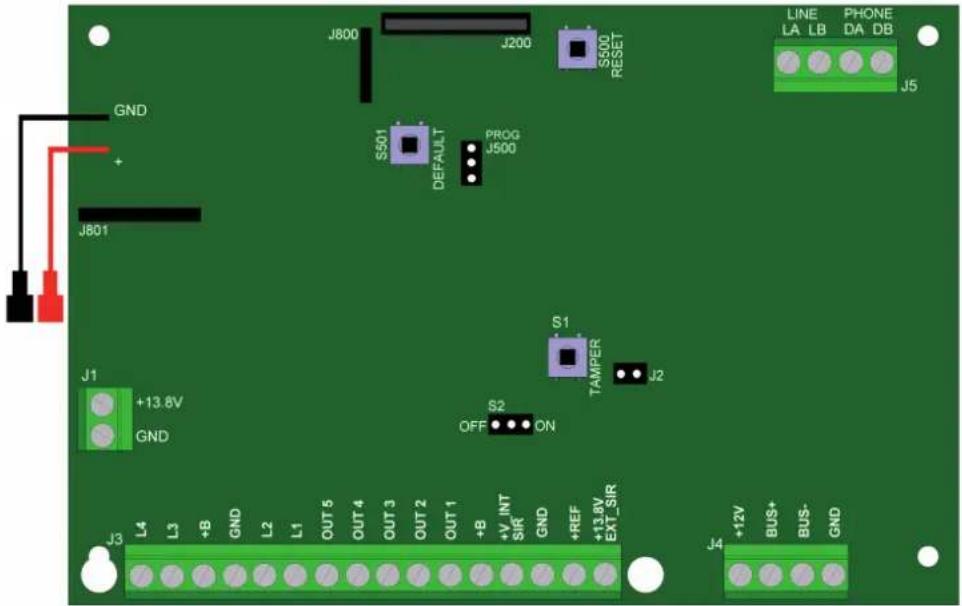
- Fuse identification:
Fuse F300: F 3.15A.
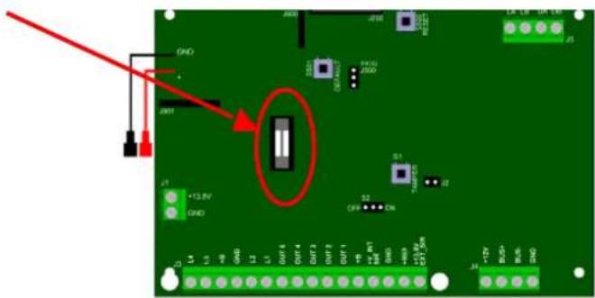
text_image
Circuit board diagram with labeled components and red annotation highlighting a component with '12.8V' and 'GND' pins.1. DESCRIPTION OF THE FEATURES
This chapter lists the main hardware and functional features of the CE2N-416 unit and the different elements and accessories that complete it.
Main features
- The control unit lines can be expanded to 4 with a M4IBUS module or to 8 with a M8IBUS module.
- Integrated software filter to detect fast alarms (for vibration or wire sensors).
- 7 outputs in the control unit.
-
4 programmable partitions.
-
Up to 4 remote keypads for managing the system and totally/partially arming the system.
- Firmware updating from PC (locally) with a MOD-USB interface module.
- 250 stored events can be displayed with the date/time/user/event displayed with the set name for better tracking.
- Partialization, even by means of an electronic key, with RFID technology (up to 4 readers for a total of 16 total keys).
- 10 codes available (1 Master code, 1 Installer code and 8 user codes that can be programmed).
Other features
- Bus length up to 1500 m.
- Anti-opening and anti-tearing protection.
- Sensor feeding activated even when the system is off.
- Specific circuit for external battery recharging.
- Walk Test Tamper function for maintenance.
- Timing block of the control unit if a false code is entered.
- Input/output time which can be programmed from 0 to 250 seconds.
- Battery control function.
- Line termination as single, double balance, normally closed, normally open, all defined for each single line (NO by default also for expansions).
- 7 outputs that can be programmed on the control unit: 1 live (positive and negative reference for sirens), 5 Open Collector (50 mA) configured by default but that can also be programmed. Activation time, activation mode, activation delay and possibility of associating key-user is also possible,
- 3 access levels: Installer/1 master user /8 users which can be modified,
- The lines can be configured as: instant alarm, burglar alarm, delayed alarm, input (key), 24h alarm/panic alarm,
- Signals from the keypad LEDs: activation/ deactivation; electric network present; tamper alarm; battery failure and expansion modules; alarm,
- 1 A feeder,
- Digital dialler with remote management (basic), Fast Format and Contact ID, 8 channels available and 16 number phone book.
2. DESCRIPTION OF THE CONTROL UNIT
- 8 input lines which can be individually programmed as normally closed or normally open, single or double balanced.
- Anti-opening and anti-tear protection.
- Plastic case.
- 12V 2Ah battery available
- 12V 1A switching feeder.
- Alarm output of self-powered siren.
- Alarm output for a siren that is not self-powered.
- 5 open collector outputs.
- Power protection against overloads, short circuits and high voltage.
- All the inputs and outputs are filtered and protected against electrical and electrostatic charges.
- Battery flat or disconnected detection circuit.
- Power for external devices, protected against overloads.
- Operating temperature: 0^ C ÷ +40°C.
The following devices are available to complete the system:
- T8N-Light - control and programming keypad with alphanumeric backlit display.
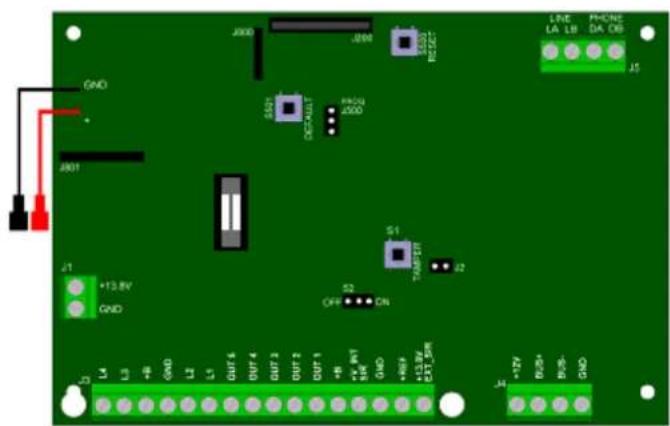
text_image
J800 J800 GND GND GND GND GND S1 TAMPER J2 S2 OFF CN +13.8V GND L4 L3 +B GND L2 L1 OUT4 OUT-4 OUT-2 OUT-1 +W -W+ W+ 16K GND +90V +13.8V EXT-5kW L4 +7V BOS BOS GND LINE LA LB PHONE DA DB J5- T8N - control and programming keypad with alphanumeric backlit display.
- CHBUS - complete reader-set of electronic keys (keys without contacts).
- M4IBUS - input expansion module.
- M8IBUS - input expansion module.
- VOCAL-416 - speech card
CE2N-416 Technical data
Power supply (tolerance) : 100-230 Vca (+10% - 15%) 50/60Hz.
Insulation class: I.
Maximum absorption from the network: 0.35A.
Rated current provided by the feeder: 1A.
Stabilized tension (tolerance): 14.2Vdc.
Continuous absorption of the basic card (external loads excluded): 100mA.
Maximum available current at the BUS485: 500mA.
Maximum available current at the output:
- +V_INT SIR : 500mA.
- OUT 1/5 : 50mA.
- +B : 500mA.
- +13.8V EXT_SIR : 500mA.
N.B. The total absorption at the outputs +13.8V EXT_SIR and +V_INT_SIR and BUS power must not exceed 500mA.
Lead battery: 2Ah 12V
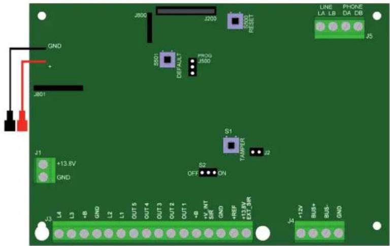
3. CE2N-416 CONTROL UNIT LAYOUT
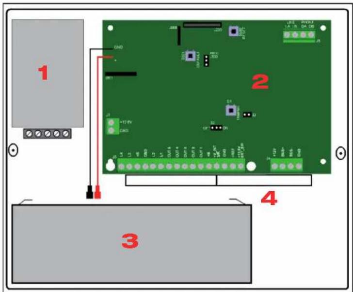
text_image
1 2 3 41: Feeder
2: Control unit card
3: Battery
4: Cable passage holes
4. INSTALLATION OF THE ONTROL UNIT
Fixing
The unit should be positioned on an even and smooth surface so that the anti-tear protection can work properly. The 4 fixing holes are located at the bottom lower corners.
How to install the control unit:
- Connect the control unit to a two-pole magneto-thermal switch. The switch must be easy to access.
- If an integrated dialer is used, install a filter to eliminate disturbance and/or filters/ splitters to eliminate the ADSL component on the line. This filter must be installed close to the fuse
box of the telephone line.
- The control unit must be installed on the wall in a position that makes it easy to access the electric cables, telephone cable, system alarm harness as well as to perform maintenance on the control unit.
- Do not install the control unit and its modules in places with extreme temperatures and humidity. For example, don't place the keypads near heat sources such as radiators or under direct sunlight, which can affect the liquid crystal display. Place the control unit and its accessories in a dry room and avoid closing the vent slots which can create a block, even partially, of internal ventilation.
4.1 Installation of the BUS RS485
The connection is performed by means of 2 conductors plus the ground conductor (negative). It is recommended to use a shielded cable. The ground is the same used to feed the devices. Take note that the bus can have parallel branches and shunts, according to the following rules:
- the total length of the bus harness (the addition of all branches and their shunts) must not exceed 1500 m.
- insert two 120 ohm 1/2W termination resistances on the bus, one resistance between the “+” and “-” terminals of the control unit and another resistance at the end of the longer pathway.
Minimum cable sections:
| Distance from the control unit “BUS+” e “BUS-” conductor Common ground conductor | ||
| Up to 400 m 0.22 mm | ^2 | 0.22 mm^2 |
| Up to 700 m 0.22 mm | ^2 | 0.5 mm^2 |
| From 700 m to 1500 m 0.44 mm | ^2 | 0.75 mm^2 |
See the following example:
120 Ohm resistance between the BUS+ terminal and BUS-terminal of the last peripheral unit.
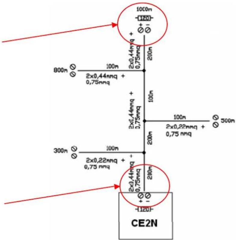
text_image
100m -120+ Ø+ Ø1 800m Ø 100m 2x0,44mmq + 0,75mmq 2x0,44mmq + 0,75mmq 300m Ø 100m 2x0,22mmq + 0,75 mmq 2x0,44mmq + 0,75mmq 200m 100m 2x0,22mmq + 0,75 mmq -120- CE2N120 Ohm resistance between the BUS+ terminal and BUS- of the control unit
5. CARD DESCRIPTION
text_image
J800 J200 S500 RESET LINE LA LB PHONE DA DB J5 GND + J801 S501 DEFAULT PROG J500 S1 TAMPER J2 J1 +13.8V GND S2 OFF ON J3 L4 L3 +B GND L2 L1 OUT 5 OUT 4 OUT 3 OUT 2 OUT 1 +B +V INT SIR GND +REF +13.8V EXT_SIR J4 +12V BUS+ BUS- GND5.1 Component description
Terminal boards
| J1 | Input terminal from the feeder |
| J3 | Terminal board for connecting inputs, outputs and power sources of the various devices connected to the control unit (see the specifi c chapter) |
| J4 | Terminal board for connecting the peripheral units connected to the BUS |
| J5 | Terminal board of input (LA-LB LINE) and output (DA-DB PHONE) of telephone line |
Jumper
| J2 | Jumper for the connection of the “anti-tear” buttonIf the jumper is not used, bridge it (closed by default) | |||
| S2 | With S2 in the ON position, the control unit Tamper is active and working | With S2 in the OFF position, the control unit Tamper is excluded. The cover can be opened without generating a tampering alarm | ||
| J500 | PROG | With J500 in this position, the control unit is working normally (by default) | PROG | With J500 in this position and after pressing the RESET key for 2 seconds, the control unit is in BOOT condition:this condition is used for Firmware updates only |
Keys
| S500 | RESET key: press this key for a few seconds to reboot the microprocessor of the control unit after a block and/or an anomaly.This operation DOES NOT cancel the programming and system settings |
| S501 | DEFAULT key: Press the “Default” and “Reset” keys simultaneously to restore the factory settings and cancel all the settings of the control unit. For performing the default procedure, follow the procedure described in paragraph 9 |
| S1 | TAMPER key can be pressed from the control unit cover. If the cover is removed during normal operations, a tampering alarm is generated |
Connectors
| J200 | Connector for the connection to MOD-USB, which is used to carry out Firmware updates of the control unit. |
| J800J801 | These 2 connectors are necessary to install and connect the speech card (optional) |
For the speech card installation, refer to the card manual VOCAL-416
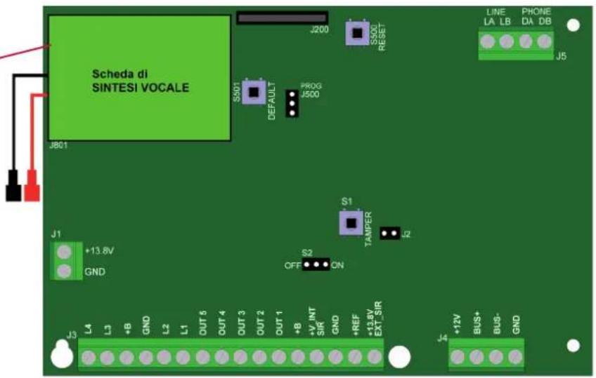
text_image
Scheda di SINTESI VOCALE J200 S500 RESET PROG J500 S501 DEFAULT J801 S1 TAMPER J2 +13.8V GND OFF S2 ON J3 L4 L3 +B GND L2 L1 OUT 6 OUT 4 OUT 3 OUT 2 OUT 1 +B +V INT SIR GND +REF +1.2V EXT_5R J4 +12V BUS+ BUS- GND LINE LA LB PHONE DA DB J55.2 Description of the terminal boards
J1 terminal board
| Terminal Features | |
| +13,8 Positive from the feeder – 13.8Vcc | |
| GND Negative from the feeder – 0Vcc |
J3 terminal board
| Terminal Features | |
| L4 Sensor connection of line 4 | |
| L3 Sensor connection of line 3 | |
| +B Feeding point no. 1 – power supply to the input devices 12Vcc 500mA max | |
| GND Ground – negative of the feeding point and sensor reference | |
| L2 Sensor connection of line 2 | |
| L1 Sensor connection of line 1 | |
| OUT5 Open collector output, which can be programmed. Negative in the event of activation. Max 50mA | |
| OUT4 Open collector output, which can be programmed. Negative in the event of activation. Max 50mA | |
| OUT3 Open collector output, which can be programmed. Negative in the event of activation. Max 50mA | |
| OUT2 Open collector output, which can be programmed. Negative in the event of activation. Max 50mA | |
| OUT1 Open collector output, which can be programmed. Negative in the event of activation. Max 50Ma Pre-configured output as SYSTEM STATUS: the output is active when the system is armed | |
| +B Feeding point no. 2 - power supply to the input devices: 12Vcc 500mA max | |
| +V_INT SIR 12 V live output which can be programmed. Programmed by default as an intrusion alarm output. Max current 500 mA. | |
| GND Ground - negative of the power supply point | |
| +REF Live output, which can be programmed. Programmed by default as a reference for the intrusion alarm. | |
| +13.8V EXT_SIR Battery charge power supply |
J4 terminal board
| Terminal Features | |
| +12V Feeding point no. 3 -power supply of BUS devices 12Vcc 500mA max | |
| BUS+ BUS line positive | |
| BUS- BUS line negative | |
| GND Ground - negative of the power supply point |
J5 terminal board
| Terminal Features | |
| LA PSTN input line “A” - LINE | |
| LB PSTN input line “B” - LINE | |
| DA PSTN input line “A” - PHONE | |
| DB PSTN input line “B” - PHONE |
Feeder terminal board
| Terminal Features | |
| L (AC) 230Vca network PHASE input | |
| N (AC) 230Vca neutral network input | |
| ± | Grounding wire connection |
| -V | GND power supply output |
| +V | +13.8V power supply output |
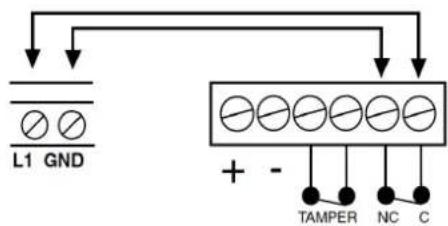
5.3 Examples of terminal connections
L1, L2, L3, L4: alarm line inputs
These terminals are connected to the contacts of the alarm detection devices.
These inputs can be individually programmed as:
- Normally closed
- Normally open
- Single balancing
• Double balancing
N.B. the value of the line's balancing resistances is always 5.6 KΩ
"Double balancing" example
"Single balancing" example
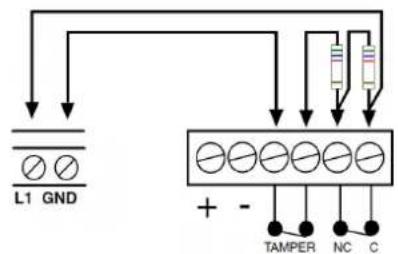
text_image
L1 GND + - TAMPER NC C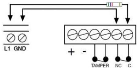
text_image
L1 GND + - TAMPER NC C"Normally closed" example"
"Normally open" example"
text_image
L1 GND + - TAMPER NC C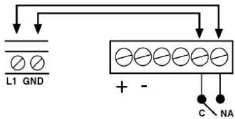
text_image
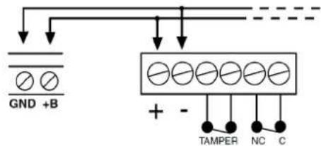
L1 GND + - C NA+B :12V live outputs, always available even when the control unit is OFF

The cables to feed the detectors and/or the additional devices are connected to this terminal.
text_image
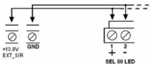
GND +B + - TAMPER NC C+13.8V EXT_SIR: live output, always available even when the control unit is OFF
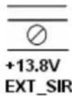
Terminal suitable to charge the buffer batteries of sirens or other self-powered devices.
text_image
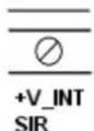
+13.8V EXT_SIR GND SEL 80 LED 1 2 + -+V_INT SIR: live output, always available during an alarm
Terminal to feed the indoor sirens (not self-powered).
text_image
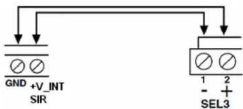
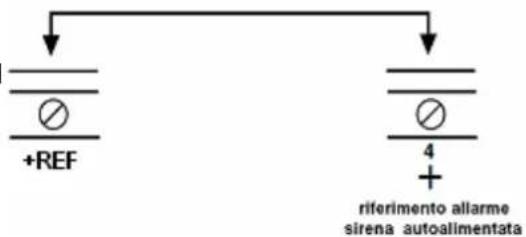
GND +V_INT SIR SEL3 1 2 - + -+REF: 12V "reference" output; this output is missing during an alarm event
Terminal with voltage that is always available but is missing when an alarm is generated. Voltage is still available after the programmed alarm time is over or when the system is deactivated.
text_image
+REF 4 + riferimento allarme sirena autoalimentataBUS: terminals for serial line connection
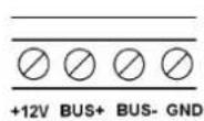
All BUS devices, such as keypads, electronic keys readers and modules for the input expansion or accessory modules are connected to these terminals.
text_image
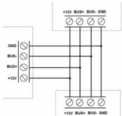
+12V BUS+ BUS- GND GND BUS- BUS+ +12V +12V BUS+ BUS- GNDOUT 1,2,3,4,5 : output connection terminals.
"Open collector" signal output. By default there is a negative at the output in accordance with the programmed activating event.
Example to activate a tone signal by an external buzzer or a display visualization by LED (12Vcc 50mA).
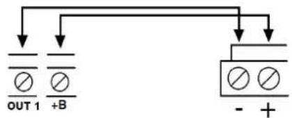
text_image
OUT 1 +B - +ATTENTION: only OUT1 is preset by default as "system status"; the output is active when the system is disarmed.
LA-LB (LINE) and DA-DB (PHONE): telephone line connection terminals.
If a PSTN line is used, connect the dialer to the network as shown in the figure:
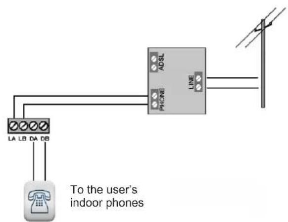
text_image
LA LB DA DB To the user's indoor phones ADSL PHONE LINE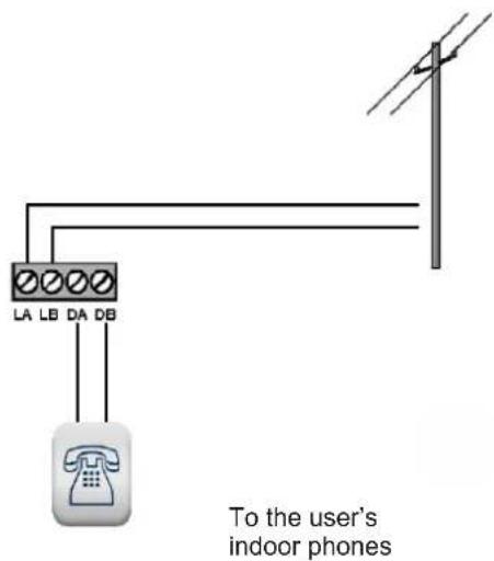
text_image
LA LB DA DB To the user's indoor phonesIf a dialer with ADSL network is used, the dialer MUST be preceded by a splitter as shown in the figure:
Feeder connection
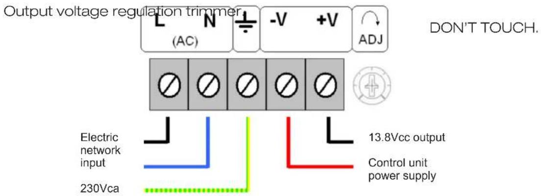
text_image
Output voltage regulation trimmer (AC) -V +V ADJ DON'T TOUCH. Electric network input 230Vca 13.8Vcc output Control unit power supply5.4 Electric safety warnings
- The building's electrical installation must fit a suitable magneto-thermal switch to protect it from surges and short circuits.
- The building's electrical installation must fit a suitable omnipolar switch. The switch must be easy to access and have a separation from the contacts of at least 3 mm. The unipolar sectioning device can be used to section the phase conductor if you are certain of having identified the neutral conductor.
- The connection conductors to the power supply network and the internal harness must be fixed with clamps or similar fixing items.
- Fuse identification:
Fusibile F300: F 3.15A.
6. FIRST SWITCHING ON OF THE CE2N-416 CONTROL UNIT
In this phase, we recommend not connecting the wires to the “+V_INT SIR” terminal and “+ REF” terminal in order to prevent the activation of the indoor and outdoor sirens.
Remember to connect the siren controls when the programming and testing are over.
Startup the control unit
- Connect the battery
- Connect the 230V network voltage
The control unit starts the startup procedure; all the alarm outputs will be activated and the keypad buzzer will start ringing to signal Tamper alarms, if any:
- Enter the MASTER code (by default 1111111)
- Press the "X" key to stop the alarms
After the alarm signalizations are stopped:
- Enter the INSTALLER code (by default 0000000)
- Begin programming.
7. CE2N-416 CONTROL UNIT PROGRAMMING
7.1 Programming keys
ATTENTION: from any point of the programming menu, use the ⏻ keys to scroll along the menu by the ⏻ key, you select an item while by the ✗ key, you exit the menu or return to the previous menu. These rules are valid for all menus.
7.2 Installer code's features (by default 0000000)
The installer code programs the entire system and is active when the installation is completely deactivated. The code has a variable length between 2 and 7 figures.
For safety reasons, the code can be entered only when the plant is disarmed (the installer code can be disabled from the master menu).
The modification of the programming code can be performed by means of the installer code only.
The installer code is accepted by any keypad of the plant.
7.3 Master code's features (default 1111111)
ATTENTION: for programming the Master code, refer to the User Master section in paragraph 10
The CE2N-416 system allows the user to have 1 master code with a variable length between 2 and 7 figures.
This code is allowed to:
- Add, change and cancel the users
- Arm the system in all the possible configurations through a scroll menu on the keypad. From the key, it is possible to globally arm the first 4 defined partitions.
• Display the historic log. - Enable the manual outputs.
- Modify the phone book.
- Manage the electronic keys (acquisition and association to a user)
• Manually exclude lines and outputs (e.g. in case of malfunctioning) - If enabled, enter the control unit via telephone (by the DTMF tone remote management) and arm the system, disarm the system, activate the output and request the status.
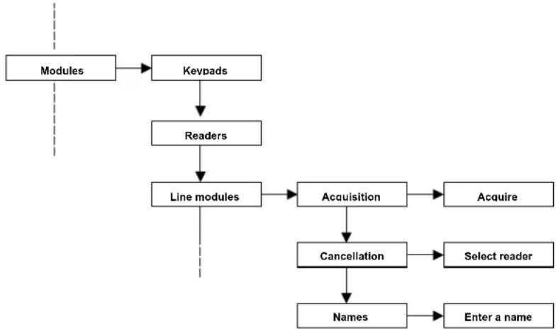
8. PROGRAMMABLE PARAMETERS
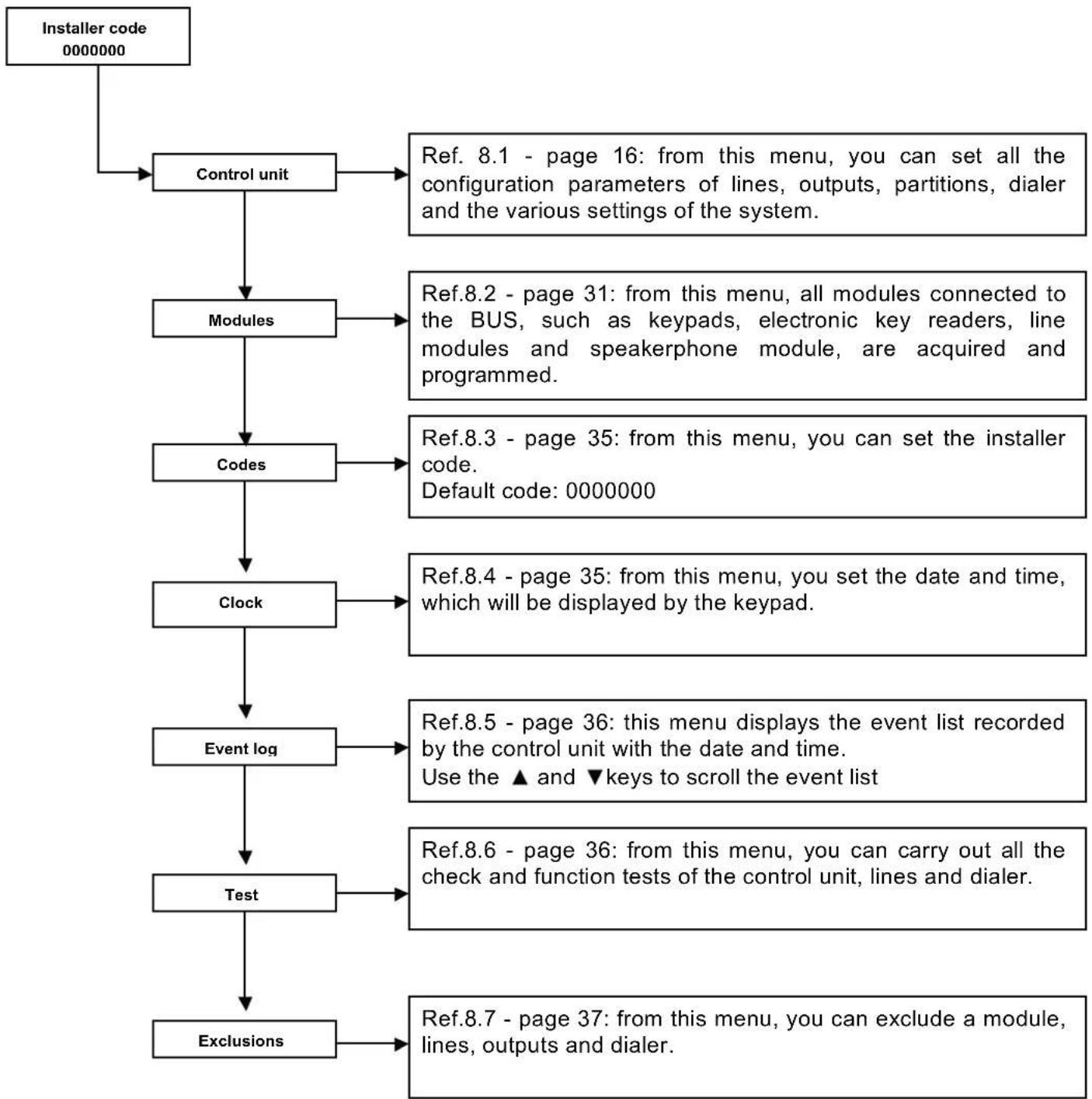
flowchart
graph TD
    A["Installer code 0000000"] --> B["Control unit"]
    B --> C["Modules"]
    C --> D["Codes"]
    D --> E["Clock"]
    E --> F["Event log"]
    F --> G["Test"]
    G --> H["Exclusions"]

    B --> I["Ref. 8.1 - page 16: from this menu, you can set all the configuration parameters of lines, outputs, partitions, dialer and the various settings of the system."]
    C --> J["Ref.8.2 - page 31: from this menu, all modules connected to the BUS, such as keypads, electronic key readers, line modules and speakerphone module, are acquired and programmed."]
    D --> K["Ref.8.3 - page 35: from this menu, you can set the installer code.<br>Default code: 0000000"]
    E --> L["Ref.8.4 - page 35: from this menu, you set the date and time, which will be displayed by the keypad."]
    F --> M["Ref.8.5 - page 36: this menu displays the event list recorded by the control unit with the date and time.<br>Use the ▲ and ▼ keys to scroll the event list"]
    G --> N["Ref.8.6 - page 36: from this menu, you can carry out all the check and function tests of the control unit, lines and dialer."]
    H --> O["Ref.8.7 - page 37: from this menu, you can exclude a module, lines, outputs and dialer."]
8.1 Control unit
8.1.1 Lines
All the control unit lines can be configured independently.
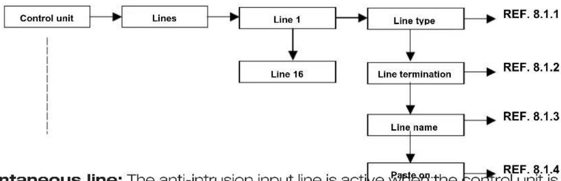
flowchart
graph TD
    A["Control unit"] --> B["Lines"]
    B --> C["Line 1"]
    C --> D["Line type"]
    D --> E["REF. 8.1.1"]
    C --> F["Line 16"]
    F --> G["Line termination"]
    G --> H["REF. 8.1.2"]
    G --> I["Line name"]
    I --> J["REF. 8.1.3"]
    I --> K["Paste on"]
    K --> L["REF. 8.1.4"]
- Instantaneous line: The anti-intrusion input line is active when the control unit is activated, even during the input and output time. An alarm activates the buzzer and the alarm LEDs on the keypads. The alarm is shown on the display.
Only the outputs and the phone channels associated with this line are activated.
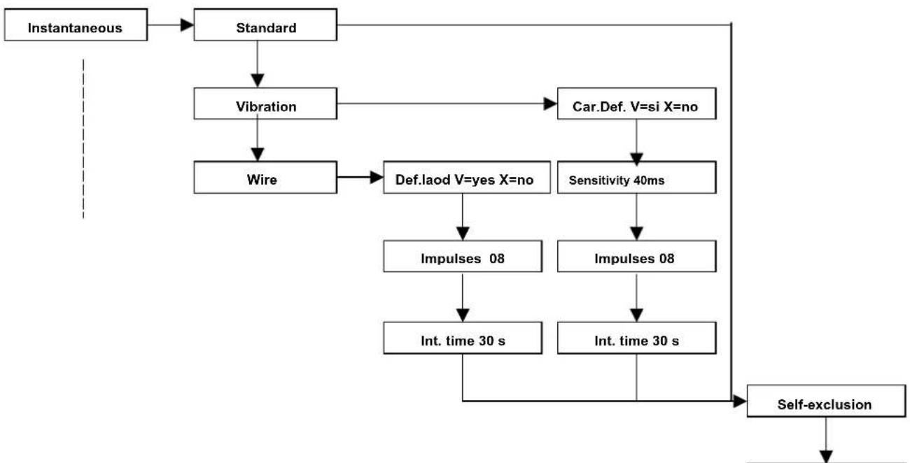
flowchart
graph TD
    A["Instantaneous"] --> B["Standard"]
    B --> C["Vibration"]
    C --> D["Wire"]
    D --> E["Def.laod V=yes X=no"]
    E --> F["Impulses 08"]
    F --> G["Int. time 30 s"]
    G --> H["Self-exclusion"]
    C --> I["Car.Def. V=si X=no"]
    I --> J["Sensitivity 40ms"]
    J --> K["Impulses 08"]
    K --> L["Int. time 30 s"]
    L --> H
Standard: setting for all traditional detectors such as volumetric sensors or perimeter contacts.
Vibration: The CE2N-416 control unit can directly connect to a vibration contact at the line input without using any other additional analysis card.
Def. Load. V=yes X=no: all the default parameters of this line type will be loaded.
Sensitivity: value expressed in milliseconds to establish how sensitive the line must be in reception.
Impulses: the number of necessary impulses that the line must receive is set before the control unit generates an alarm.
Int. time: the setting of the "integration time" defines the time by which the control unit must count the "impulse number" set in the item of the previous menu.
Wire: The CE2N-416 control unit can connect a roller wire contact directly to the line input without using any additional analysis card.
Def. Load. V=yes X=no: this procedure allows you to load the default parameters set for this type of line.
Impulses: the number of necessary impulses that the line must receive is set before the control unit generates an alarm.
Int. time: the setting of the "integration time" defines the time by which the control unit must count the "impulse number" set in the item of the previous menu.
Self-excl. activat.: if the line is open during the activation time when the "output time" is finished, the line is automatically excluded from the control unit and the alarm will not be generated.
- Delayed line: The anti-intrusion input line is active when the control unit is activated, only from the moment in which the output time is finished. After the output time, if the line is in the alarm status, the input time begins and, during this time, the line does not generate an alarm so that the control unit can be disarmed by the keypad or the electronic key. If the control unit is not deactivated, an alarm condition will be activated. Therefore, a buzzer, the alarm LED on the keypads and all the outputs associated with this line will be activated. The alarm is visible from the display. For each line of these, it is possible to define separate input and output times.
flowchart
graph TD
    A["Modules"] --> B["Keypads"]
    B --> C["Acquisition"]
    C --> D["Acuire"]
    C --> E["Cancellation"]
    E --> F["Configuration"]
    F --> G["Keyspad 00"]
    G --> H["Keyspad 04"]
    F --> I["Names"]
    I --> J["Enter name"]
    style A fill:#f9f,stroke:#333
    style J fill:#bbf,stroke:#333
Standard: setting for all traditional detectors, such as volumetric sensors or perimeter contacts.
Vibration: The CE2N-416 control unit can directly connect to a vibration contact at the line input without using any other additional analysis card.
Def. Load. V=yes X=no: all the default parameters of this line type will be loaded.
Sensitivity: value expressed in milliseconds to establish how sensitive the line must be in reception.
Impulses: the number of necessary impulses that the line must receive is set before the control unit generates an alarm.
Int. time: the setting of the "integration time" defines the time by which the control unit must count the "impulse number" set in the item of the previous menu.
Wire: The CE2N-416 control unit can connect a roller wire contact directly to the line input without using any additional analysis card.
Def. Load. V=yes X=no: this procedure allows you to load the default parameters set for this type of line.
Impulses: the number of necessary impulses that the line must receive is set before the control unit generates an alarm.
Int. time: the setting of the "integration time" defines the time by which the control unit must count the "impulse number" set in the item of the previous menu.
Output time: delay time to activate the single line from the moment in which the system is on. When the system is activated by the keypad or the electronic key, the output time begins counting. Each delayed or internal instantaneous line can be associated to a specific output time (from 0 to 255 seconds) during which the line can be open without causing an alarm. If, after the "Output time" is finished, the contact is still open, the control unit generates an alarm.
Input time: in the condition of activated system, if an alarm is generated on a delayed line, the count of the set input time is activated (each delayed line has its own input time that is from 0 to 255 sec.). Within this interval, the control unit does not generate an alarm, provided that the other no-delayed lines (instantaneous, internal instantaneous, etc.) do not cause an alarm. If the control unit is not deactivated after this time is passed, an alarm will be generated.
Self-exclusion: if the line is open during the activation time when the “output time” is finished, the line is automatically excluded from the control unit and the alarm will not be generated.
- Anti-burglar line: The input line is active whether the control unit is ON or OFF. When an alarm of this type is generated, a delay time starts. It can be programmed for each line.
If the alarm is still going off after this time is completed, the associated outputs are activated. If the alarm turns off before the delay time finishes, no associated outputs are activated.
No sound or visual signal is emitted by the keypads. Only the outputs and the phone channels associated to this line are activated.
The alarm is not detected if you are within the installer menu.
- Panic line: input line activated whether the control unit is ON or OFF. If an alarm is generated, all the associated outputs are activated as well as the buzzer and the alarm LED on the keypads. The alarm is visualized on the display. Only the outputs associated to this line are activated. The alarm is not detected if you are within the installer menu.
- 24 hour line: input line activated whether the control unit is ON or OFF. If an alarm is generated, the line activates the associated outputs, the buzzer and the alarm LED on the keypads. The alarm is visualized on the display. The alarm is not detected if you are within the installer menu.
- Key line: This line allows the user to send commands to the control units that deal with activation, deactivation or activation and/or deactivation of a control output.
The choice of activation is made by the user. The total activation or deactivation will be carried out for that code.
Impulse type: This option allows the user to determine the command given by means of the key. If it is IMPULSIVE, the line has to be unbalanced for a certain amount of time to generate the command and then the line will return to stand-by (for example, by key) or STABLE in which every variation of status (opened or closed) generates the command (for example: switch).
Control type: The controls that can be performed by the key line are as follows:
- Activation or deactivation of the selected code: the control unit is activated or deactivated. The activation type is the total of the specified code.
- Activation and deactivation of the output: the control unit outputs can be piloted from the key line but they must be set as manual within the output menu.
ATTENTION: the "STABLE" control within the "activation and deactivation" function
prevents the keypads and the readers from working because the line “requires” the activation and does not allow other control devices from being deactivated.
- Line termination: After defining the typology of the line and all the other subparameters that define the line type, the line termination will have to be defined.
Each input can be programmed independently as follows:
• Normally closed input
• Single balancing input
• Double balancing input
• Normally open input
(see harness example from page 13)
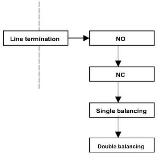
flowchart
graph TD
    A["Line termination"] --> B["NO"]
    B --> C["NC"]
    C --> D["Single balancing"]
    D --> E["Double balancing"]
- Assigning a name to the line: Each line can be sociated with a name, which is different than the one set at the factory, such as LINE01, LINE02, .... LINE16. This function facilitates the use of the end user.
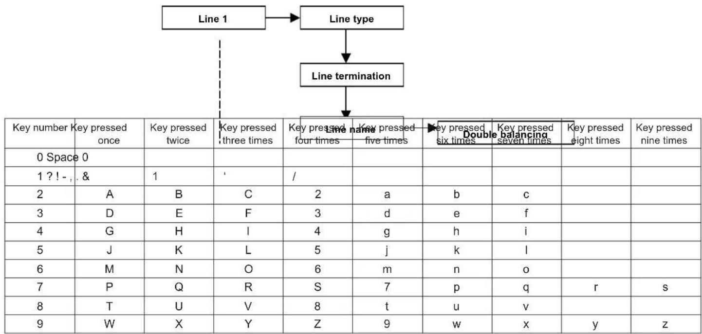
flowchart
graph TD
    A["Line 1"] --> B["Line type"]
    B --> C["Line termination"]
    C --> D["Key number: Key pressed once, 0 Space 0"]
    D --> E["Key pressed twice, 1 ? ! - , & 1"]
    E --> F["Key pressed three times, 2, 3, 4, 5, 6, 7, 8, 9"]
    F --> G["Key pressed four times, Key pressed five times, Key pressed six times, Double balancing, Key pressed seven times, Key pressed eight times"]
    G --> H["Key pressed five times, Key pressed six times, Key pressed seven times, Key pressed eight times"]
- Paste on: After programming the line, the same settings can be applied to the other lines by entering the “paste on ...” menu item and later defining the line on which to paste the settings except for the line name:
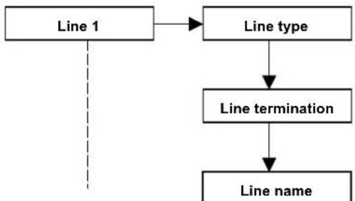
flowchart
graph TD
    A["Line 1"] --> B["Line type"]
    B --> C["Line termination"]
    C --> D["Line name"]
8.1.2 Outputs
The control unit is equipped with 5 outputs that can be programmed freely.
- +REF, live output with positive reference that is configured at 12V when the system is not generating an alarm (the output is mainly used for the external self-powered siren control)
- +V_INT SIR, live output with 12V under alarm (the output is mainly used for the internal siren control),
• OUT 1, open collector output
• OUT 2, open collector output,
• OUT 3, open collector output,
• OUT 4, open collector output,
• OUT 5, open collector output.
- Output status. By this item, you set the output stand-by:
Normally active: the control tension is present in the output when it is in the normal operating condition.
Normally inactive: the control tension is NOT present in the output when it is in the normal operating condition.
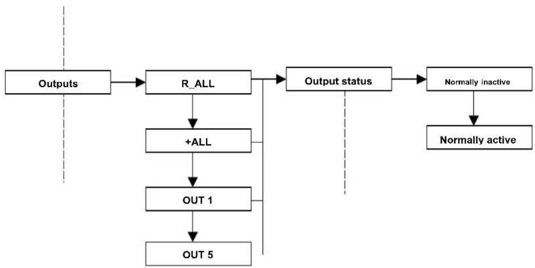
flowchart
graph TD
    A["Outputs"] --> B["R_ALL"]
    B --> C["+ALL"]
    C --> D["OUT 1"]
    D --> E["OUT 5"]
    B --> F["Output status"]
    F --> G["Normally inactive"]
    G --> H["Normally active"]
- Output type. By this item, you can program the output operating mode: Define if the output is:
Impulse: its activity follows the status of events to which it is associated, but, unlike the stable type, it generates an impulse for as long as you want. The activation delay time and the activation time must be programmed. An impulse line can be restored only after the activation time or after entering a code that is enabled to deactivate the output.
Stable: its activity follows the status of the events it is associated with. The output is activated by an active event condition and deactivated after the event is restored.
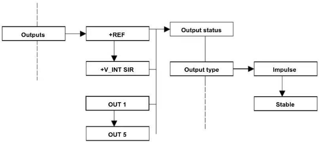
flowchart
graph TD
    A["Outputs"] --> B["+REF"]
    B --> C["+V_INT SIR"]
    C --> D["OUT 1"]
    D --> E["OUT 5"]
    B --> F["Output status"]
    F --> G["Output type"]
    G --> H["Impulse"]
    H --> I["Stable"]
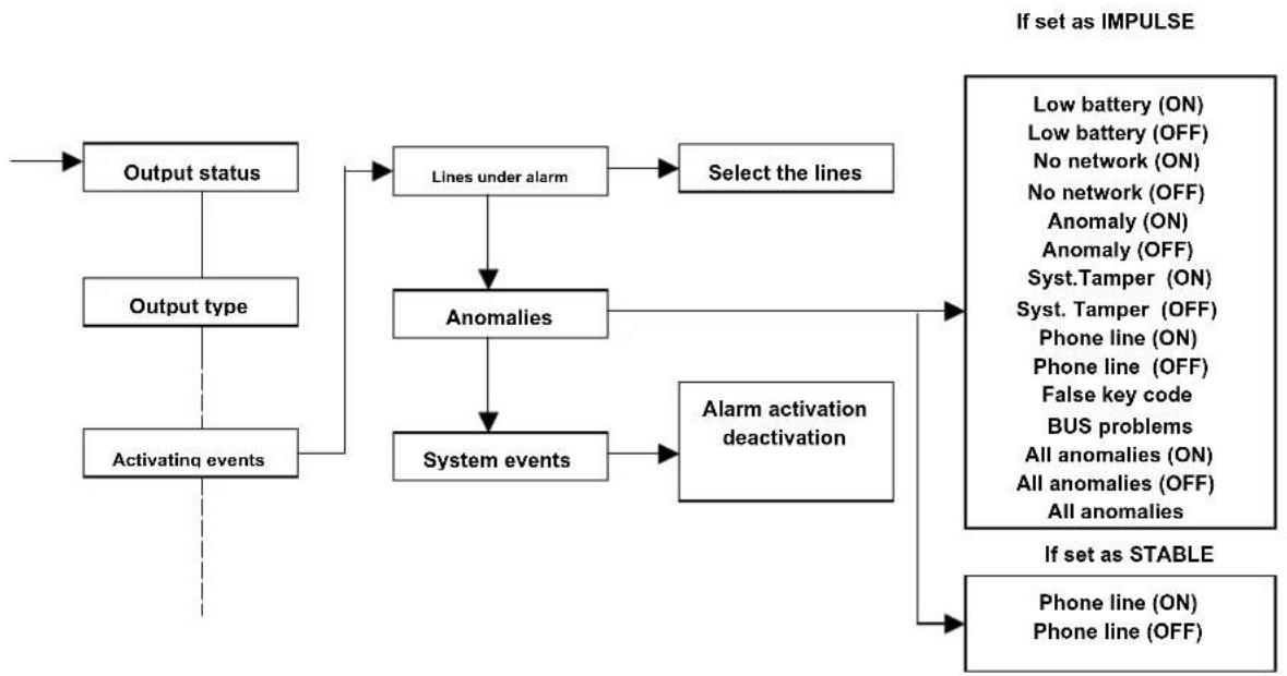
- Activating events. Each output is associated to the events that activate it. Select the event which switches its status for each output.
flowchart
graph TD
    A["Output status"] --> B["Lines under alarm"]
    C["Output type"] --> B
    D["Activating events"] --> B
    B --> E["Select the lines"]
    B --> F["Anomalies"]
    F --> G["System events"]
    G --> H["Alarm activation deactivation"]
    H --> I["If set as IMPULSE"]
    H --> J["If set as STABLE"]
    I --> K["Low battery (ON)"]
    I --> L["Low battery (OFF)"]
    I --> M["No network (ON)"]
    I --> N["No network (OFF)"]
    I --> O["Anomaly (ON)"]
    I --> P["Anomaly (OFF)"]
    I --> Q["Syst.Tamper (ON)"]
    I --> R["Syst. Tamper (OFF)"]
    I --> S["Phone line (ON)"]
    I --> T["Phone line (OFF)"]
    I --> U["False key code"]
    I --> V["BUS problems"]
    I --> W["All anomalies (ON)"]
    I --> X["All anomalies (OFF)"]
    I --> Y["All anomalies"]
ATTENTION: the words (ON) and (OFF) at the end of the writing identifies if the event must control the output with an armed control unit (ON) or a disarmed control unit (OFF).
- Output settings:
Activation delay: a delay from the event to the effective activation of the output can be defined for the impulse and stable outputs
Activation duration: the duration of the output under an alarm can be defined for the impulse outputs
Manual output: enables the output to be displayed for the manual activation from the keypad or telephone. The modes to activate the manual outputs of the CE2N-416 are as follows:
- keys of the T8N and T8N-Light keypads,
- Within the Master or user menu there is the "Manual Output" submenu",
- By remote telephone access,
• Key lines.
Output name: the CE2N-416 allows the naming of the outputs as well as the lines. This function facilitates the use for the user.
Paste on .. : among the options that can be selected, it is possible to paste the settings of an output onto another one (except for the output's name)
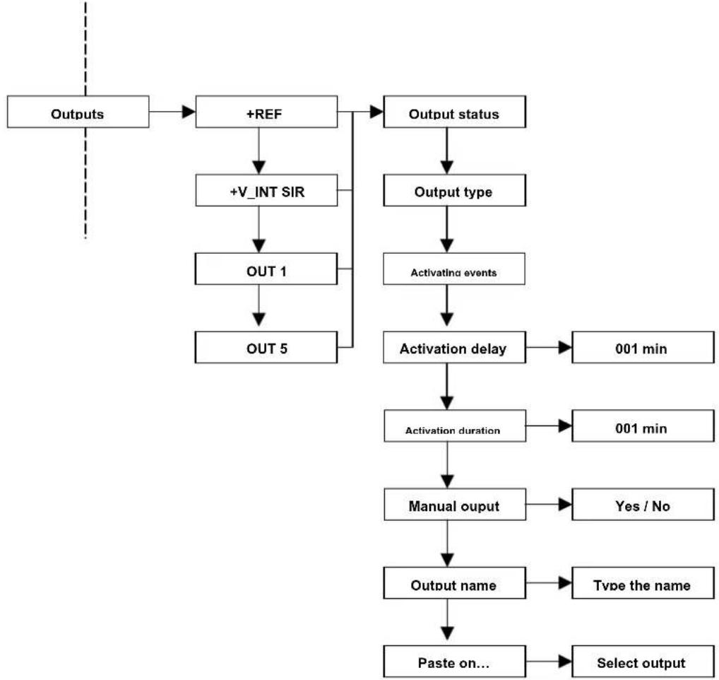
flowchart
graph TD
    A["Outputs"] --> B["+REF"]
    B --> C["+V_INT SIR"]
    C --> D["OUT 1"]
    D --> E["OUT 5"]
    B --> F["Output status"]
    F --> G["Output type"]
    G --> H["Activating events"]
    H --> I["Activation delay"]
    I --> J["001 min"]
    I --> K["Activation duration"]
    K --> L["001 min"]
    K --> M["Manual output"]
    M --> N["Yes / No"]
    M --> O["Type the name"]
    M --> P["Paste on..."]
    P --> Q["Select output"]
8.1.3 Partitions
The system offers different insertion types depending on the needs.
The system lines can be gathered in partitions. Therefore, a partition is a logical gathering of lines, such as the night and day partition. The total number of partitions that can be configured for the whole control unit is 4.
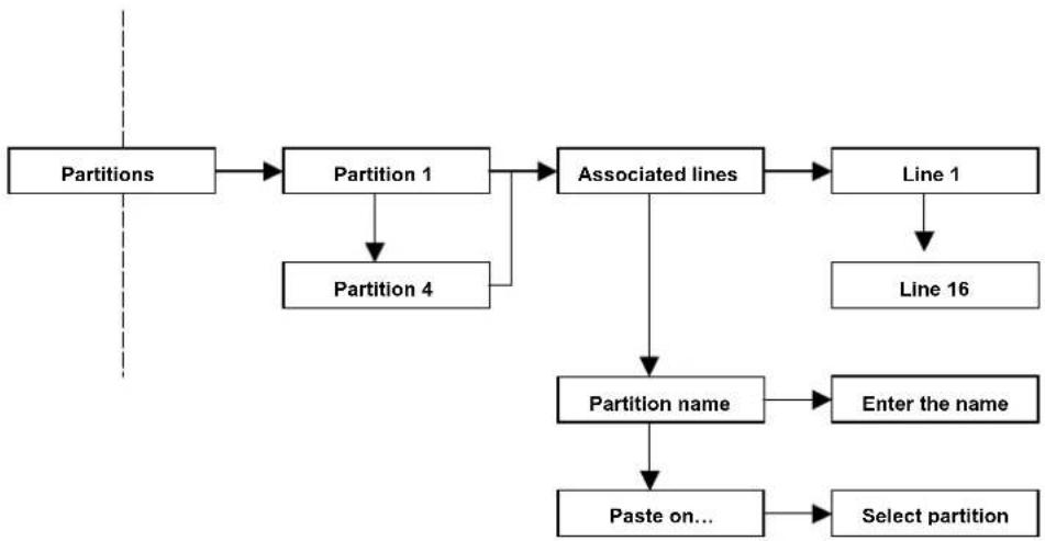
flowchart
graph TD
    A["Partitions"] --> B["Partition 1"]
    B --> C["Associated lines"]
    C --> D["Line 1"]
    D --> E["Line 16"]
    B --> F["Partition 4"]
    C --> G["Partition name"]
    G --> H["Enter the name"]
    G --> I["Paste on..."]
    I --> J["Select partition"]
- Associated lines: this parameter defines how many and which outputs will be active with this partition.
- Partition name: every partition can be renamed; this function facilitates the use for the end user.
- Paste on... : among the selectable options, there is the possibility to copy the settings of a partition onto another (partition name excluded).
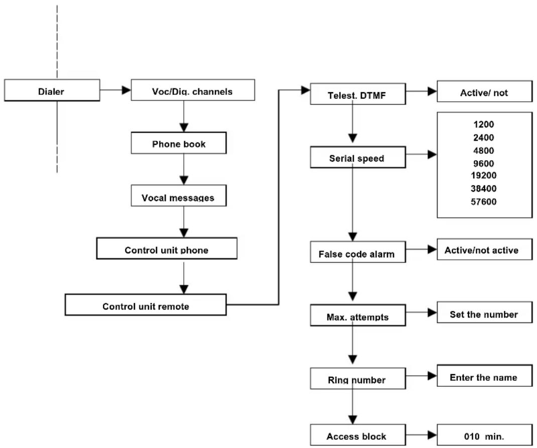
8.1.4 Dialler
A digital dialler for the PSTN analogue lines is integrated in the control unit. An optional vocal synthesis card can also be integrated in the dialler.
The dialler allows the normal alarm calls as well as the following:
The remote management: by the DTMF tones with vocal guide (only if the VOCAL-416 card is installed) you can control the system remotely by calling the control unit via phone; the control unit answers, it authenticates the user who enters his/her code and, if enabled, a vocal menu is given. The menu offers the following functions:
- Arming / disarming / request for an area status
-Activation / deactivation / request for a manual output status
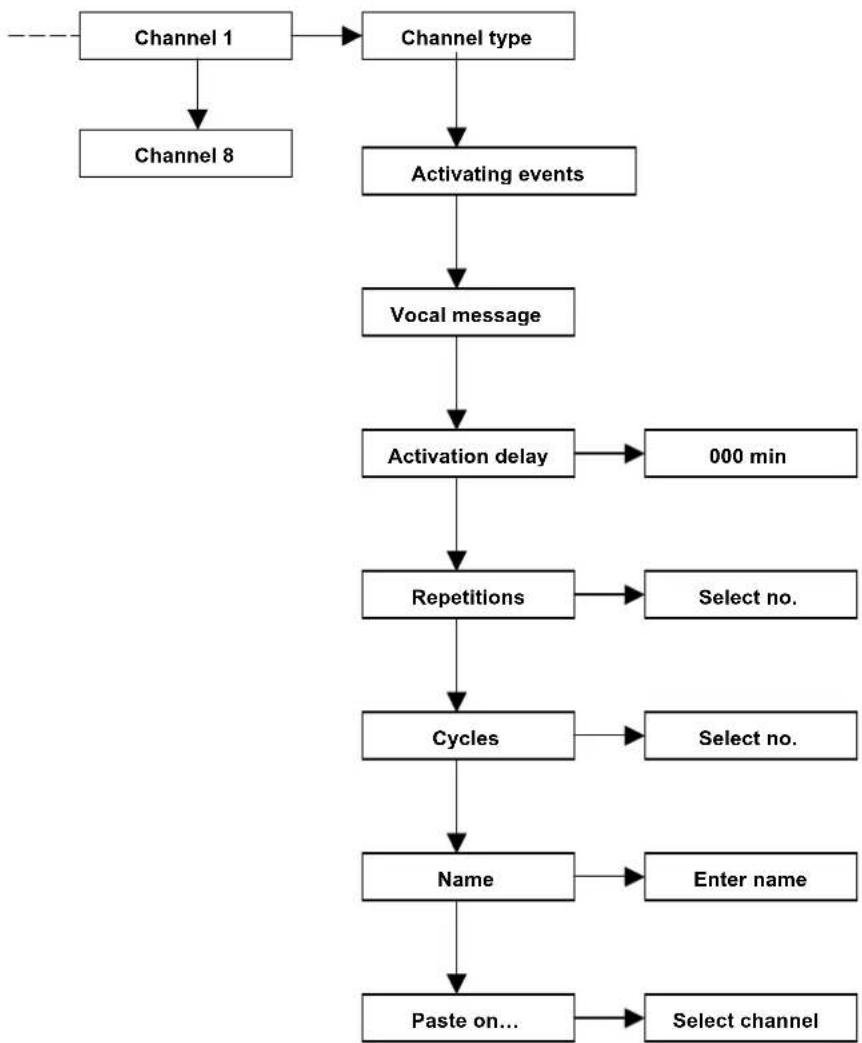
- Channel type. By this item, you can program the channel operation type:
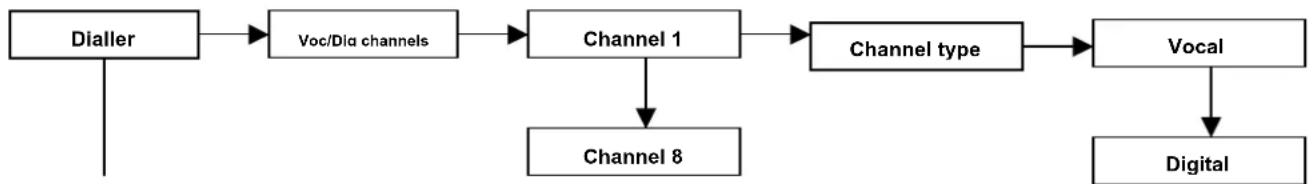
flowchart
graph LR
    A["Dialer"] --> B["Voc/Dia channels"]
    B --> C["Channel 1"]
    C --> D["Channel type"]
    D --> E["Vocal"]
    E --> F["Digital"]
    C --> G["Channel 8"]
Vocal: send a vocal message to warn the user that an alarm has been released.
ATTENTION: if the vocal synthesis card is not installed, it is possible to interact remotely with the control unit only by means of DTMF tones. In the event of an alarm, there will be a call which will emit a ring tone similar to the tone emitted by the keypad under an alarm
Digital: digital alarm messages are sent to the security centres in accordance with the Fast Format and Contact ID protocols.
Differences between vocal and digital channels: Every event of the control unit can activate an alarm “channel.” 8 channels are available and a maximum of 8 can be digital and the remaining ones are of vocal synthesis.
The parameters to be set are as follows:
Digital channel
- Protocol
- system code
- cycle number (1..7)
- ratio codes
- event codes
- interval and calling time of a test
• number to call (among those in the phone book)
Vocal channel
- numbers to call (among those in the phone book),
- repetition number (from 1 to 7),
- DTMF confirmation activated by a user code valid for the area (if enabled, the remote management can be carried on),
• total block activation
• vocal message to send - cycles
- activating events
- Activating events (of the channel set in vocal):
By this item, you can program the event (or the events) that generate a phone call
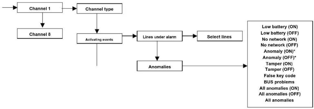
flowchart
graph TD
    A["Channel 1"] --> B["Channel type"]
    C["Channel 8"] --> D["Activating events"]
    B --> D
    D --> E["Lines under alarm"]
    E --> F["Select lines"]
    F --> G["Anomalies"]
    G --> H["Low battery (ON)"]
    G --> I["Low battery (OFF)"]
    G --> J["No network (ON)"]
    G --> K["No network (OFF)"]
    G --> L["Anomaly (ON)*"]
    G --> M["Anomaly (OFF)*"]
    G --> N["Tamper (ON)"]
    G --> O["Tamper (OFF)"]
    G --> P["False key code"]
    G --> Q["BUS problems"]
    G --> R["All anomalies (ON)"]
    G --> S["All anomalies (OFF)"]
    G --> T["All anomalies"]
*The anomalies (ON-OFF) are the following: control unit overload, no battery, failure of microprocessor.
ATTENTION: the specification (ON) and (OFF) at the end of the writing identifies if the event must control the output with an armed control unit (ON) or a disarmed control unit (OFF)
- Vocal Messages (if the VOCAL-416 card is present):
Up to 8 vocal custom messages of 5 sec each can be memorized and 1 address message lasting 10 seconds.
The vocal messages can be recorded and listened to by means of a microphone and loudspeaker which are equipped with the vocal synthesis card.
The message can be chosen among the pre-recorded ones:
• Anti-burglar alarm
- Intrusion alarm
- Emergency alarm
- First aid alarm
• Technological alarm
- Tamper alarm
- Lack of network
- failure of the control unit
And the custom messages:
- Custom message from 1 to 8
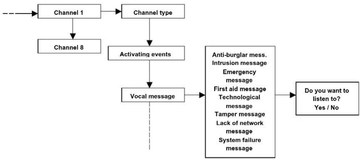
flowchart
graph TD
    A["Channel 1"] --> B["Channel type"]
    C["Channel 8"] --> D["Activating events"]
    B --> D
    D --> E["Vocal message"]
    E --> F["Anti-burglar mess. Intrusion message Emergency message First aid message Technological message Tamper message Lack of network message System failure message"]
    F --> G["Do you want to listen to? Yes / No"]
ATTENTION: for storing custom messages 1 to 8 and the address message (common message which will be played after the channel messages), see programming of REF 8.1.4.3.3, page 35.
- Various channel settings
Activation delay: a delay from the event to the effective activation of the channel can be defined from the moment the alarm is released
Repetitions: this parameter defines the times the associated vocal message is repeated during the call
Cycles: this parameter defines the times that the telephone numbers associated to the channel will be called (except for the block made by the user) for the alarm in progress
Name: each channel can be named again; this function facilitates the user of the end user.
Paste on ... : among the options that can be selected, it is possible to paste the settings of a channel onto another one (except for the channel's name)
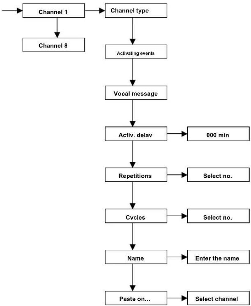
flowchart
graph TD
    A["Channel 1"] --> B["Channel type"]
    B --> C["Activating events"]
    C --> D["Vocal message"]
    D --> E["Activ. delay"]
    E --> F["000 min"]
    E --> G["Repetitions"]
    G --> H["Select no."]
    G --> I["Cycles"]
    I --> J["Select no."]
    I --> K["Name"]
    K --> L["Enter the name"]
    K --> M["Paste on..."]
    M --> N["Select channel"]
- Phone book. From the phone book, identify the PHONE NUMBER of the person to call in the event of an alarm; this number will be associated to the channel or to the channels relevant to the various alarm events.
16 numbers from the phone book are available; they can be associated independently to the 8 channels.
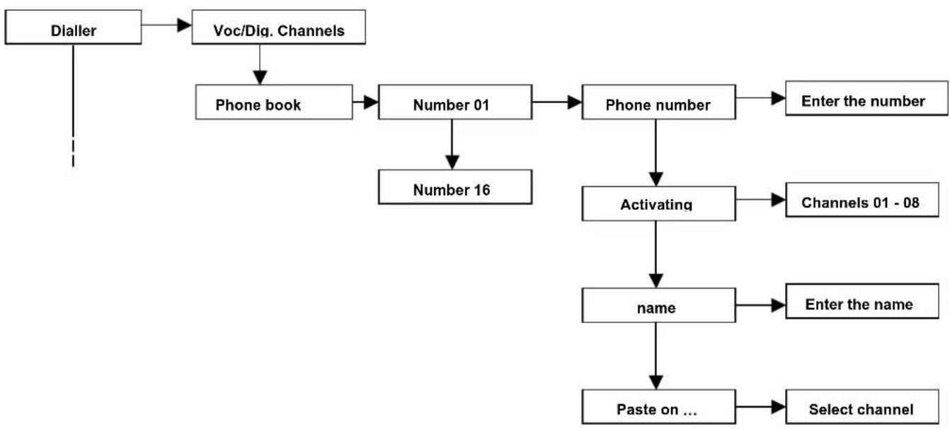
flowchart
graph TD
    A["Dialler"] --> B["Voc/Diq. Channels"]
    B --> C["Phone book"]
    C --> D["Number 01"]
    D --> E["Number 16"]
    E --> F["Phone number"]
    F --> G["Enter the number"]
    F --> H["Activating"]
    H --> I["Channels 01 - 08"]
    H --> J["name"]
    J --> K["Enter the name"]
    J --> L["Paste on ..."]
    L --> M["Select channel"]
Telephone number: enter the telephone number or the mobile number that the dialler will dial in the event of an alarm.
Activating channels: defines the channels that will activate the call to the associated phone number
Name: each number from the Phone Book can be renamed; this function facilitates the use for the end user.
Paste on ... : The setting of a number from the Phone Book can be copied onto another number (channel name excluded)
- Vocal messages
ATTENTION: this menu section is activated only if there is the VOCAL-416 speech card From the phone book, identify the PHONE NUMBER of the person to call in the event of an alarm; this number will be associated to the channel or to the channels relevant to the various alarm events. 16 numbers from the phone book are available; they can be associated independently to the 8 channels.
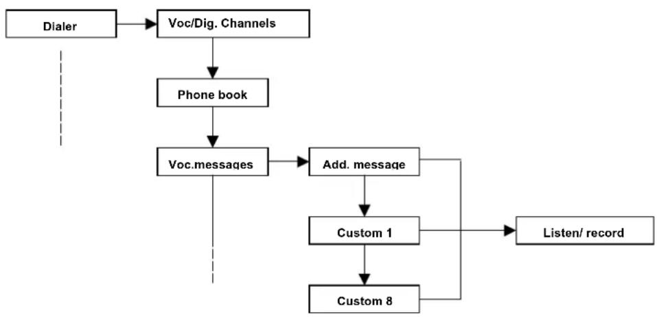
flowchart
graph TD
    A["Dialer"] --> B["Voc/Dig. Channels"]
    B --> C["Phone book"]
    C --> D["Voc.messages"]
    D --> E["Add. message"]
    E --> F["Custom 1"]
    F --> G["Custom 8"]
    G --> H["Listen/ record"]
Address message: (max. length 10 seconds) now program the message that will be played after the message from a specific channel. It is normally used to record the address with the personal details of the system owner.
Custom message from 1 to 8: (maximum length of 5 seconds) if the pre-recorded channel messages are not sufficient or if you want to identify the alarm of a precise zone/event, the system allows the recording of 8 custom messages.
- Message recording
- To record, select the message you want from the installer programming menu of the keypad, go to the item "RECORD" and confirm by selecting V;
- Position yourself in front of the speech card installed on the control unit card and start recording;
- Press the RECORD key on the top of the VOCAL-416 (keep the key pressed for the entire recording time);
- Speak at about 10 – 15 cm from the microphone (do not exceed the maximum time of the message)
ATTENTION: Refer to the manual contained in the card packaging for information about the installation of the VOCAL-416 card
Listening to the messages
- select the message you want from the installer programming menu to listen to the message
- select the item "LISTEN" and press V to confirm;
- the recorded message will be played by the loudspeaker connected to the control unit (check that the out speaker is connected to the speech card).
- Optional telephone functions of the control unit
The dialler can be customized with specific optional telephone functions to control the line:
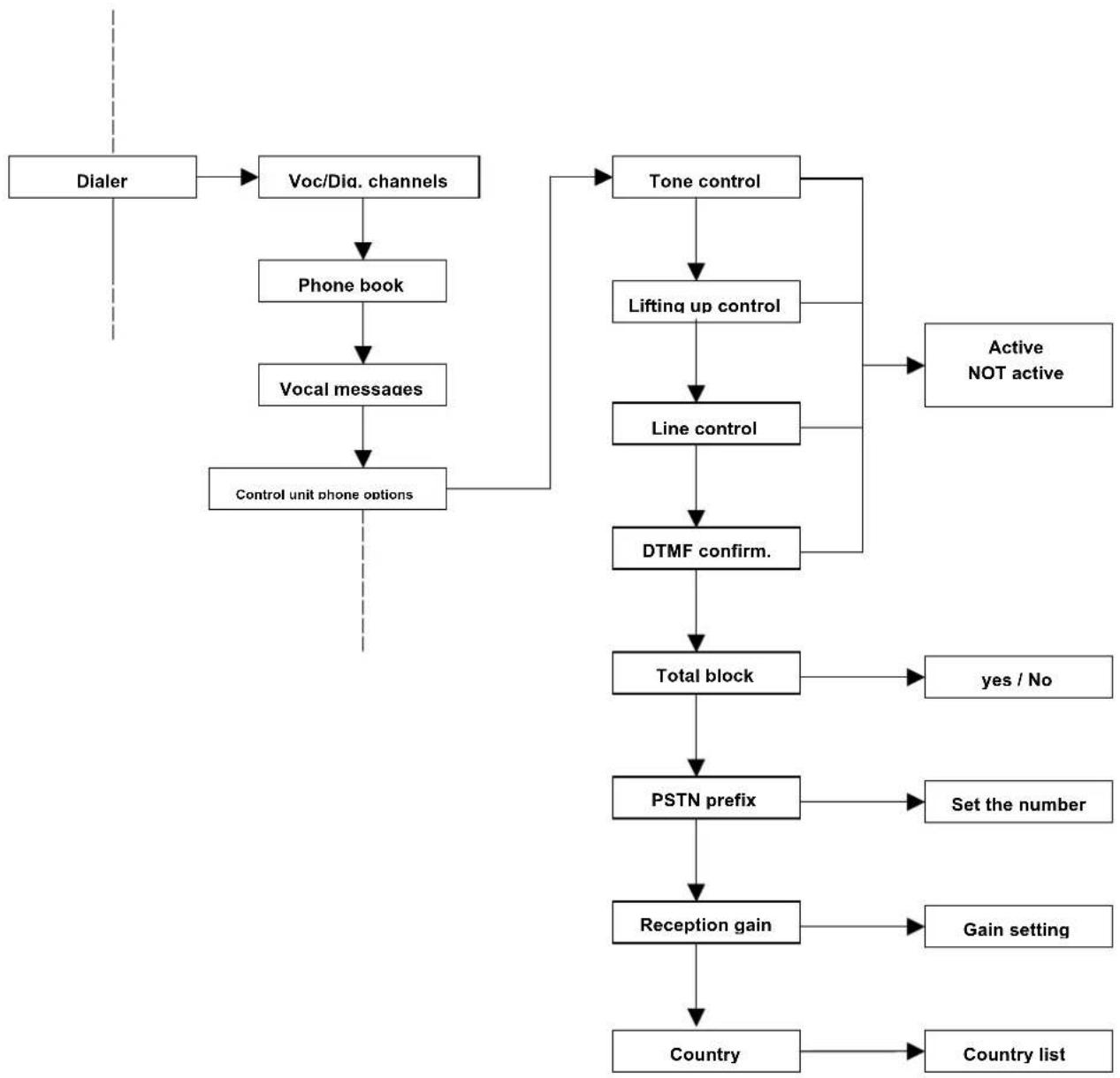
flowchart
graph TD
    A["Dialer"] --> B["Voc/Dia. channels"]
    B --> C["Phone book"]
    C --> D["Vocal messages"]
    D --> E["Control unit phone options"]
    E --> F["Tone control"]
    F --> G["Lifting up control"]
    G --> H["Line control"]
    H --> I["DTMF confirm."]
    I --> J["Total block"]
    J --> K["yes / No"]
    J --> L["PSTN prefix"]
    L --> M["Set the number"]
    M --> N["Reception gain"]
    N --> O["Gain setting"]
    N --> P["Country list"]
    F --> Q["Active NOT active"]
Tone control: defines if the dialler must check the tones that comes from the phone line (free, engaged,...).
Lifting of the receiver: if this option is activated, you can check if the call has been received. It is detected if the receiver is lifted up because of the absence of a ring-back (the call is successful even when an answering machine answers).
Line control: when activated, the dialler continuously monitors the presence of the phone line (an alarm condition can be generated).
DTMF confirmation: if this function is active, all the following calls to the user who has answered an alarm call are blocked; the block occurs if after (or during) the message is being listened, the confirmation code is dialled on the phone (the code is defined in the Master menu and is activated by default with the number 555).
Total block: If this function is enabled, the called user can block the whole call sequence by dialling the confirmation code from his phone after (or during) he is listening to the message. If this function is not activated, when the confirmation code is entered, only the following calls to that number will be blocked and not the whole sequence. The TOTAL BLOCK function is enabled only if the DTMF CONFIRMATION function has been activated before. The default setting is active.
PSTN prefix: Set the PSTN prefix by entering a number from 0 to 9. This figure is entered before the phone number to connect the control unit's dialler to a phone exchange.
Reception gain: allows you to select the sensitivity of the telephone, which is 0dB by default. Modify this parameter only if there are problems to receive the DMTF tones. See the paragraph "DTMF reception test."
Country: allows you to choose the COUNTRY where the control unit will be installed. This function automatically modifies the parameter to make the MODEM fit the different protocols of the telephone lines of each country
| Australia Cyprus Great Britain Ireland Malta Spain | |||||
| Austria Czech Republic Greece Italy Mexico Sweden | |||||
| Belgium Denmark Hong Kong New Zealand | Japan New Zealand Taiwan | ||||
| Brazil Finland Hungary Korea Poland Thailand | |||||
| Bulgaria | France | Iceland | Luxembourg | Portugal | Tunisia |
| China | Germany | India | Malaysia | Singapore | U.S./Canada |
- Remote optional functions of the control unit
The dialler can be customized with specific optional functions of the control unit to control the line:
flowchart
graph TD
    A["Dialer"] --> B["Voc/Diq. channels"]
    B --> C["Phone book"]
    C --> D["Vocal messages"]
    D --> E["Control unit phone"]
    E --> F["Control unit remote"]
    F --> G["Telest. DTMF"]
    G --> H["Active/ not"]
    G --> I["Serial speed"]
    I --> J["False code alarm"]
    J --> K["Active/not active"]
    J --> L["Max. attempts"]
    L --> M["Set the number"]
    L --> N["Ring number"]
    N --> O["Enter the name"]
    N --> P["Access block"]
    P --> Q["010 min."]
DTMF remote management: if this function is active, the control unit can be managed remotely by a DTMF tone telephone.
Serial speed: used to test the control unit only
False code alarm: enables the generation of an alarm in the event that a false code is entered
Maximum number of attempts: maximum number of attempts to enter a false code before the alarm is generated.
Ring number: number of rings that the control unit must hear before allowing remote access. This function is useful if an answering machine device is used in parallel with the dialler of the control unit.
Access block: After the MAX. ATTEMPT number has been exceeded, this function allows you to block access to the control unit for a set time (by default 10 minutes).
Example of programming an alarm channel:
flowchart
graph TD
    A["Channel 1"] --> B["Channel type"]
    B --> C["Activating events"]
    C --> D["Vocal message"]
    D --> E["Activation delay"]
    E --> F["000 min"]
    E --> G["Repetitions"]
    G --> H["Select no."]
    G --> I["Select no."]
    G --> J["Cycles"]
    J --> K["Enter name"]
    J --> L["Name"]
    L --> M["Paste on..."]
    M --> N["Select channel"]
A) Select the channel type. Vocal or digital
B) Select the events that will trigger the virtual dialler
Alarm lines
Anomalies
C) Select which message, among the recorded ones, the virtual dialler must send. You can choose a preset message or customized one (custom messages from 1 to 8).
D) Return to the "Phone dialler" menu and select "Phone book."
E) Choose one or more positions in the phone book that you want the virtual dialler to call (i.e. the CHANNELS)
F) Store the telephone number for the chosen positions.
G) Then choose one or more activating channels (previously programmed) that the virtual dialler is to link to that number.
H) It is also possible to name the phone number for a faster search.
I) From the dialler submenu "Vocal Messages," you can find the item "ADDRESS Message" which is the identification number of the house from where the call for aid is coming.
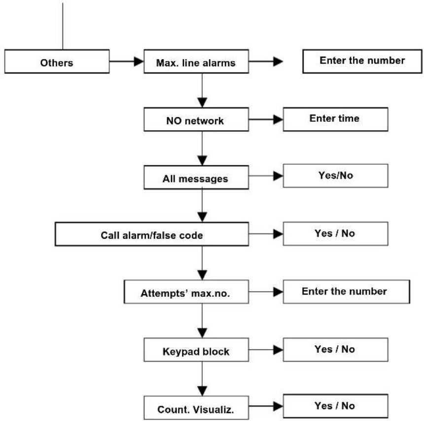
8.1.5 Other
The OTHER menu includes various functions which customize the operations of the control unit.
flowchart
graph TD
    A["Others"] --> B["Max. line alarms"]
    B --> C["NO network"]
    C --> D["All messages"]
    D --> E["Call alarm/false code"]
    E --> F["Attempts' max.no."]
    F --> G["Keypad block"]
    G --> H["Count. Visualiz."]
    B --> I["Enter the number"]
    C --> J["Enter time"]
    D --> K["Yes/No"]
    E --> L["Yes / No"]
    F --> M["Enter the number"]
    G --> N["Yes / No"]
    H --> O["Yes / No"]
    I --> P["End"]
    J --> Q["End"]
    K --> R["End"]
    L --> S["End"]
    M --> T["End"]
    N --> U["End"]
    O --> V["End"]
    P --> W["End"]
    Q --> X["End"]
    R --> Y["End"]
    S --> Z["End"]
    T --> AA["End"]
    U --> AB["End"]
    V --> AC["End"]
    W --> AD["End"]
    X --> AE["End"]
    Y --> AF["End"]
    Z --> AG["End"]
Max line alarm – this parameter sets the maximum number of alarms that a line can cause before it is automatically excluded from the control unit (because of a switching in progress)
No electric network - is set after a certain amount of time that there is a loss of network tension in which the control unit sends off calls of alarm. The control unit will consider this event an anomaly and, if programmed, it inserts it into the historic log
All messages – disables or enables the visualization of all the indications (open line, activations, etc.) on the keypad display.
KEY/False code alarm - enables the generation of an alarm in the event that a false code is entered repeatedly or a non-acquired key is brought up to the reader.
• If activated by the keypad, the telephone channel associated to the event starts
- If activated by the reader, a general alarm is released, the sirens emit a sound and the associated phone channel is activated
MAX number of attempts - maximum number of attempts to enter a false code before the keypad is temporarily blocked and a possible signal of a false code (if activated) is generated.
Keypad block -max. number of ATTEMPTS to enter the code from the keypad before the keypad blocks. To activate the keypad block, enable "KEY ALARM / FALSE CODE".
Continuous display - enables or disables the continuous display on the LEDs of the key reader. The option allows the display of the control unit status if the continuous display is disabled only when the key is approached for 5 seconds.
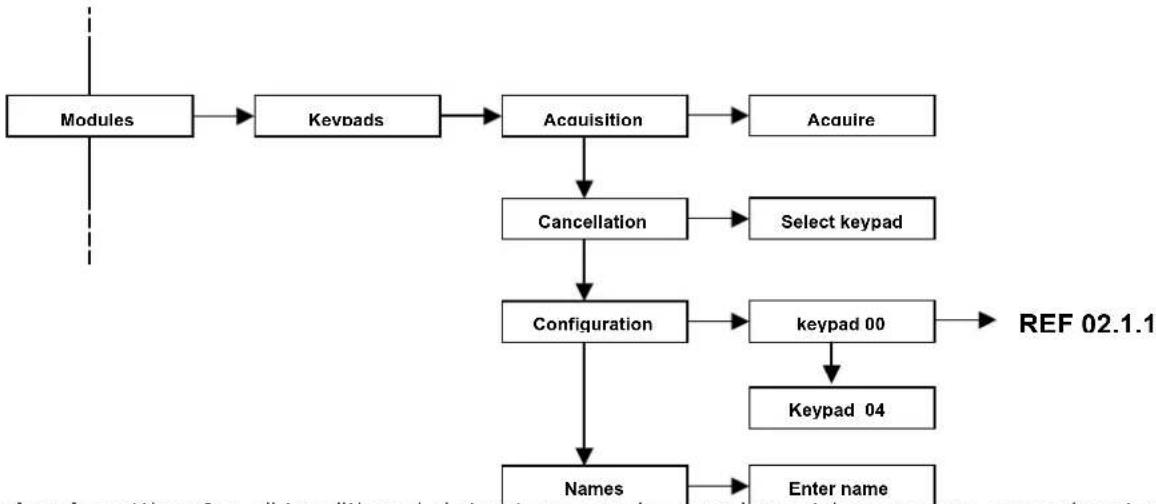
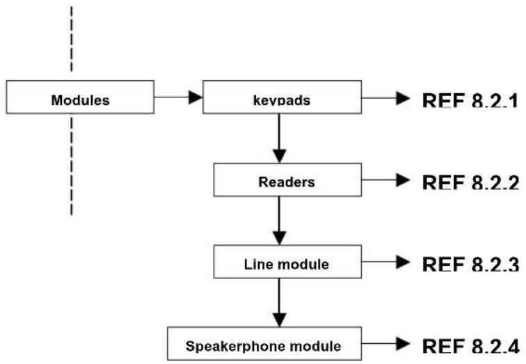
8.2 MODULES
From this section, you can acquire or cancel the additional MODULES connected to the BUS as well as program the relevant parameters.
flowchart
graph TD
    A["Modules"] --> B["keypads"]
    B --> C["Readers"]
    C --> D["Line module"]
    D --> E["Speakerphone module"]
    B --> F["REF 8.2.1"]
    C --> G["REF 8.2.2"]
    D --> H["REF 8.2.3"]
    E --> I["REF 8.2.4"]
ATTENTION: before acquiring the various modules, make sure that the dip-switches (excluded the CH-BUS readers) are set correctly.
For each type of family, the first module starts from the address "0"
8.2.1 Keypads
The keypad integrated in a plastic case is equipped with a backlighting LCD display and a status LED. Up to 4 remote keypads can be connected to the BUS of the CE2N-416 control unit.
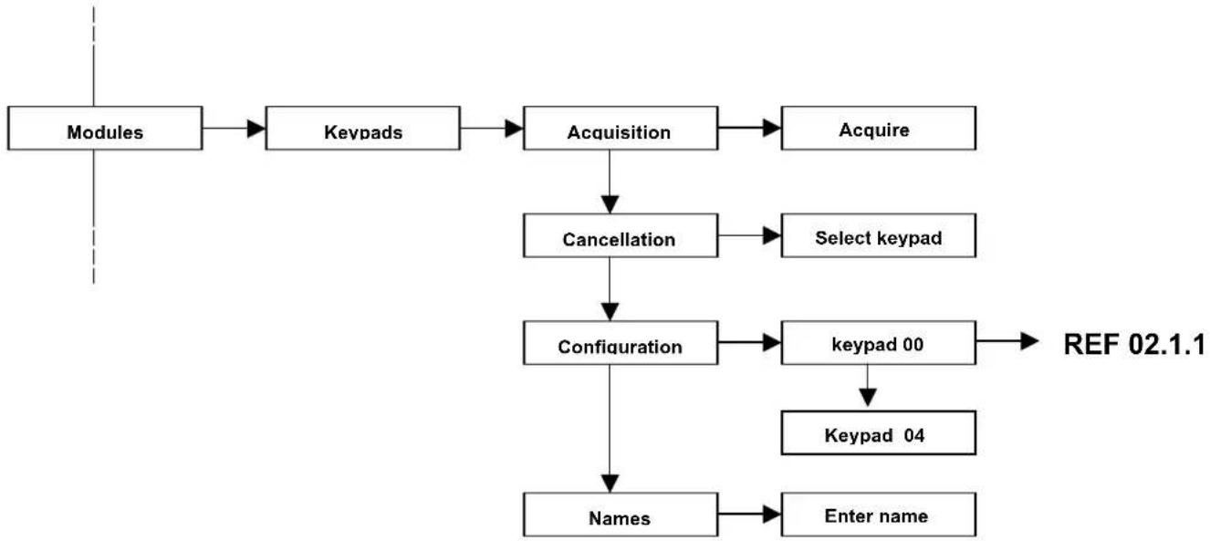
flowchart
graph TD
    A["Modules"] --> B["Keypads"]
    B --> C["Acquisition"]
    C --> D["Acquire"]
    C --> E["Cancellation"]
    E --> F["Select keypad"]
    E --> G["Configuration"]
    G --> H["Keypad 00"]
    H --> I["Keypad 04"]
    G --> J["Names"]
    J --> K["Enter name"]
    G --> L["REF 02.1.1"]
- Input lines of the keypads present in the T8N keypad
Each T8N keypad has two local input lines with the "Normally Closed" configuration. They can be used to connect the sensors.
In this case, the T8N keypad works as an input module, which is recognized by the control unit with the same address of the keypad.
For the acquisition of these 2 lines, dip-switch no. 7 of the T8N keypad must be positioned to ON and then the keypad must be acquired as an input module.
A new 2-line input module will be acquired.
ATTENTION Do not exceed the maximum limit of 16 inputs managed by the control unit:
Example: 4 control unit lines + 8 M8IBUS lines = 12 OK
4 control unit lines + 2 keypad lines + 8 M8IBUS lines = 14 OK
4 control unit lines + 8 M8IBUS lines + 4 M4IBUS lines + 2 keypad lines = 18 NO
- Keypad parameters
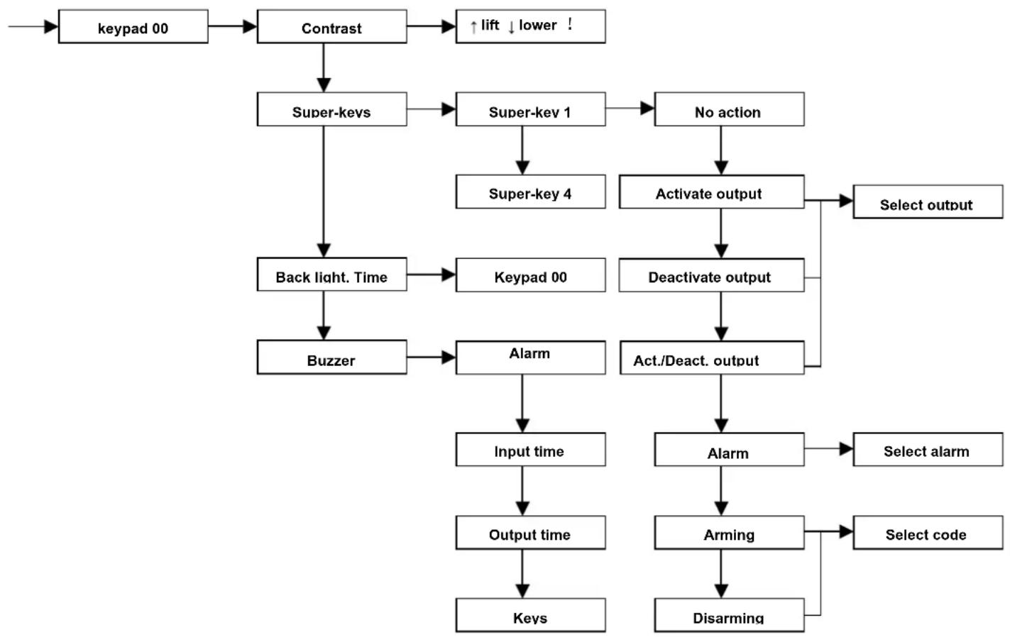
flowchart
graph TD
    A["Keypad 00"] --> B["Contrast"]
    B --> C["Super-keys"]
    C --> D["Back light. Time"]
    D --> E["Buzzer"]
    E --> F["Alarm"]
    F --> G["Input time"]
    G --> H["Output time"]
    H --> I["Keys"]
    B --> J["↑ lift ↓ lower !"]
    C --> K["Super- Key 1"]
    K --> L["Super-key 4"]
    L --> M["Activate output"]
    M --> N["Select output"]
    D --> O["Keypad 00"]
    O --> P["Deactivate output"]
    P --> Q["Act./Deact. output"]
    Q --> R["Alarm"]
    R --> S["Select alarm"]
    Q --> T["Arming"]
    T --> U["Select code"]
    T --> V["Disarming"]
Contrast – the installer can freely regulate the contrast of the characters on the display directly from the keypad. This will give the best possible visibility, depending on where the keypad is fixed to the wall.
Super-KEYS – fast keys can be set for each keypad by pressing the F1, F2, F3, F4 keys without entering any valid code.
This function allows any user to perform the functions quickly and easily. These functions can be defined during the installer menu programming phase. The following options can be chosen:
• ARMING/DISARMING
Arming can be performed by associating a super-key to a user's code.
ATTENTION: if the system can be disarmed with the super-keys, the anti-intrusion system is no longer safe because any person can switch it off without entering a valid code.
• OUTPUT ACTIVATION
The only activation that can be performed, associating a super-key to an output that was previously set as manual (see chapter relevant to the output configuration).
The control cannot be activated in the event that the selected output is already active.
• OUTPUT DEACTIVATION
The deactivation can be performed by associating a super-key to an output that was previously configured as manual (see the chapter relevant to the output configuration).
The control cannot be activated in the event that the selected output is already deactivated.
• ACTIVATION/ DEACTIVATION OF AN OUTPUT
This function allows you to activate or deactivate an output according to the status in which it was previously.
- ALARM
Various line types can be associated to the alarm from super-keys. This function allows the generation of an alarm in accordance with the programming of the line type. The alarm types are as follows:
• Anti-intrusion: this alarm type is generated only if the system is partially or totally armed
• Anti-burglar: this alarm type is generated if the system is on or off
- Panic: this alarm type is generated if the system is on or off
The activation of an alarm from super-keys will set off all phone calls to the numbers that are input in the programming of the dialler.
Each keypad has 4 super-keys; each super-key can be associated to different controls even simultaneously. The super-key programming is possible to perform from the keypad; therefore, each keypad has super-keys with different controls in accordance with the installation place and the personnel's need.
Backlighting time – In this programming phase, you can adjust the keypad backlighting to enter the digits more easily if the room is scarcely lit.
If there is no power, the backlighting of the keys and display turns off automatically to decrease absorption and not to overcharge the battery.
The time can be regulated for 15, 30, 45, or 60 seconds.
Buzzer – the funzioning of the buzzer can be configured independently in each keypad; one of the following signalizations can be chosen:
- alarm sound
- input time scanning,
• output time scanning
- beep when a key is pressed
8.2.2 Transponder key readers
The reader takes advantage of the transponder technology and is integrated in a plastic case suitable to the 503 built-in module (Magic support); the reader allows the activation of the system both partially or completely by an electronic "key".
Up to 4 readers for the electronic key can be connected to the bus, the key management is performed by the control unit. The maximum number that the control unit can manage is 16.
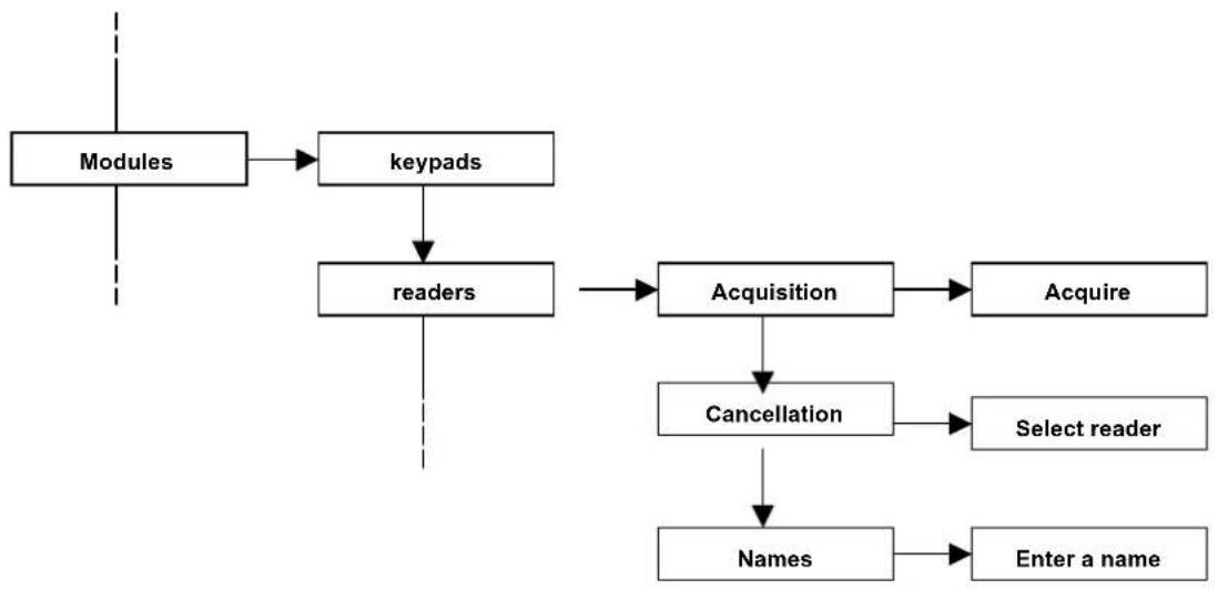
flowchart
graph TD
    A["Modules"] --> B["keypads"]
    B --> C["readers"]
    C --> D["Acquisition"]
    D --> E["Acquire"]
    C --> F["Cancellation"]
    F --> G["Select reader"]
    C --> H["Names"]
    H --> I["Enter a name"]
- Acquisition of the reader
The reader doesn't have a dip-switch for defining the address number. The acquisition procedure is different from the procedure of the other modules and consists of simply bringing a key to the reader when the control unit is in “Reader acquisition” mode.
Activate the "Acquisition" item from the readers' menu:
The LED indications in the reader are as follows:
- all LEDs permanently ON: reader acquired
- all LEDs flashing rapidly: the reader is under acquisition but not yet stored by the control unit

When the LEDs are flashing, bring the CH10BG electronic key up to the reader; when the acquisition is complete, the flashing LEDs will be permanently ON.
Follow the same methods for all the other system readers
The acquisition is confirmed by a sound tone from the keypad, which also displays the number of the acquired modules.
The number of the readers will be automatic and progressive and will follow the acquisition number
Example: the first memorized reader will be the number 0; the second will be the number 1, etc.
Attention: Do not install the CH-BUS module near the magnetic fields (for example, transformers, dimmers, etc.) that may affect the operation. The minimum distance of installation between the two CH-BUS modules is 20 cm.
ATTENTION: during this programming phase, the CH10BG key that was used to acquire and codify the readers was NOT scanned and, therefore, at the moment, it is not enabled for activations.
For the key memorization, refer to the procedure given in the user's manual.
- Cancellation of the reader. From this menu item, you can cancel the readers which will be removed from the system. After selecting the “Cancellation” function, select the reader
- Name. each input module can be renamed for being identified; this function facilitates the use for the end user.
8.2.3 Line modules
The module allows the expansion of 8 lines by means of a terminal board. The module is equipped with electronic devices to manage fast alarms (vibration, wire ..) and another terminal for the connection of the case tampering. Furthermore, it presents the terminals to power supply the sensors.
flowchart
graph TD
    A["Modules"] --> B["Keypads"]
    B --> C["Readers"]
    C --> D["Line modules"]
    D --> E["Acquisition"]
    E --> F["Acquire"]
    D --> G["Cancellation"]
    G --> H["Select reader"]
    D --> I["Names"]
    I --> J["Enter a name"]
- Acquisition of the line module. Before the acquisition, make sure that the dip-switches of the module are set correctly
Example:
Acquisition of 2 M4IBUS modules
Setting the 1st module = 0
Setting the 2nd module = 1
Acquisition of 1 M8IBUS module
Setting the module = 0
If a T8N is present and a 2 internal input module is present, pay attention that the module will be addressed with the same keypad number (if the keypad is 0, the internal module is 0). Pay attention not to create an address conflict and that the maximum limit of 16 inputs managed by CE2N-416 control unit in the various combination is not exceeded.
Acquisition of 2 2-line modules on 2 T8N keypads (dip no. 8 positioned to ON in both modules)
Setting the 1st module = 0 (address of the keypad 0)
Setting the 2nd module=1 (address of the keypad 1)
Activate the “Acquisition” item from the menu relevant to the Line Modules and, after a few seconds, all the acquired modules will be displayed.
- Cancellation of the Line Module. From this menu item, you can cancel all modules, which are removed from the system. After selecting the “Cancellation” function, select the reader
- Name. Each input module can be named again for being identified; this function facilitates the identification of the installer in the event that a failure occurs.
8.3 Installer code (by default 0000000)
The installer code programs all the system.
The code has a variable length between 2 and 7 figures. For security reasons, the code is active when the installation is completely deactivated (the installer code can be disabled from the master
menu).
This code can be modified by the installer's menu only.
The installer code can be entered from any system keypad.
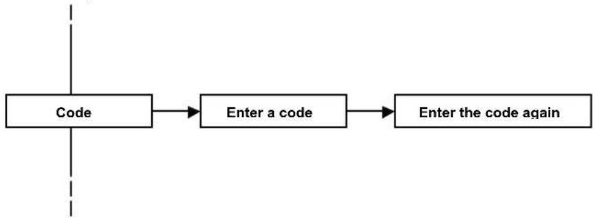
flowchart
graph LR
    A["Code"] --> B["Enter a code"]
    B --> C["Enter the code again"]
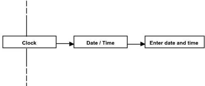
8.4 Clock
The control unit keeps date and time to write the event log and authenticate the user codes.
Attention: the clock function is not kept in the event that the power source is missing (no network and flat battery).
flowchart
graph LR
    A["Clock"] --> B["Date / Time"]
    B --> C["Enter date and time"]
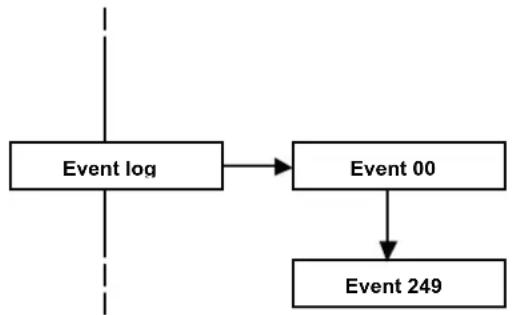
8.5 Historic log
The control unit memorizes up to 250 events permanently with the date and time. All the system events are always visible from any keypad, as well as any control unit anomaly and the accesses of the various users, master and installer.
The following signalizations are added to the dialer when a call is sent:
T= line tone
A=lifting up
O= engaged
C= Confirmation code
D= Digital alarm
flowchart
graph TD
    A["Event log"] --> B["Event 00"]
    B --> C["Event 249"]
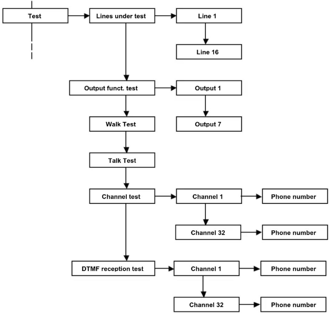
8.6 Test
Specific functions can be used to check the correct operation of the system.
flowchart
graph TD
    A["Test"] --> B["Lines under test"]
    B --> C["Line 1"]
    C --> D["Line 16"]
    B --> E["Output funct. test"]
    E --> F["Walk Test"]
    F --> G["Talk Test"]
    G --> H["Channel test"]
    H --> I["DTMF reception test"]
    E --> J["Output 1"]
    J --> K["Output 7"]
    H --> L["Channel 1"]
    L --> M["Phone number"]
    H --> N["Channel 32"]
    N --> O["Phone number"]
    L --> P["Channel 1"]
    P --> Q["Phone number"]
    P --> R["Channel 32"]
    R --> S["Phone number"]
- Lines being tested
The CE2N-416 control unit allows you to test the lines without it activating the alarm outputs and the tone signals from the keypads.
Under the test mode, the line is activated according to the programmed modes (for example, a delayed line keeps the input/output time, even when it is being tested).
An alarm on the lines being tested is signalled on the keypad display, on the red LED of the keypad and on the key reader. The alarm is recorded in the historic log.
A line being tested generates a self-protection alarm (if the line is configured as single or double balancing).
ATTENTION: if a line is excluded manually or it is being TESTED and the system is COMPLETELY ARMED, the CHBUS reader will show the LED permanently green (all armed), the keypad will display the zone/s excluded, even if the system is completely armed, and it will display the words "CENTRALE PARTE INSERITA". The event log will record the exclusion of the zone/s and, if the system is completely armed with one excluded zone, the words "TOTAL ACTIVATION" will be displayed.
- Output function test. The CE2N-416 control unit allows for the testing of all alarm outputs on the card by activating each of them for about 3 seconds.
- Walk test. The control unit allows you to quickly and efficiently check the correct operation of the sensors and modules.
Place the control unit in “line walk test” mode and activate the sensors that you want to control. The keypad buzzer will generate a tone every time that the sensor is activated and the activation will be recorded on the display.
Press the key no. 5 on the keypad to reset the alarm.
- Walk test Tamper. The control unit allows you to quickly and efficiently check the proper operation of the anti-tampering sensors. Place the control unit in “walk test tamper” mode and open the cases of the sensors that you want to control. The keypad buzzer will generate a tone every time that the contact is activated and the activation will be recorded on the display. Press the key no. 5 on the keypad to reset the alarm.
- Channel test. The control unit allows you to test the telephone alarm channel and the correct dispatch of the vocal and/or digital signals to a specific number. The call is sent without generating any effective alarm.
- DTMF reception test. The control unit can test the DTMF tone reception.
This test allows you to understand if the CE2N-416 control unit recognizes the DTMF tones sent by a phone line from a telephone.
Select an active channel and an associated phone number; press V to call.
• Answering the incoming call
• NO message is heard
- Press the various digits 1,2,3,4,5,6,7,8,9,0,*,# from the PHONE keypad
- From the display of the T8N and/or T8N-Light keypads, the same figures that are pressed on the phone will appear in the same sequence.
If the numbers don't appear, modify the sensitivity of the telephone from the menu
Dialler ▶ control unit phone options ▶ reception gain
If the problem is not solved, check th-e connection and/or check the signal quality of the incoming phone line.
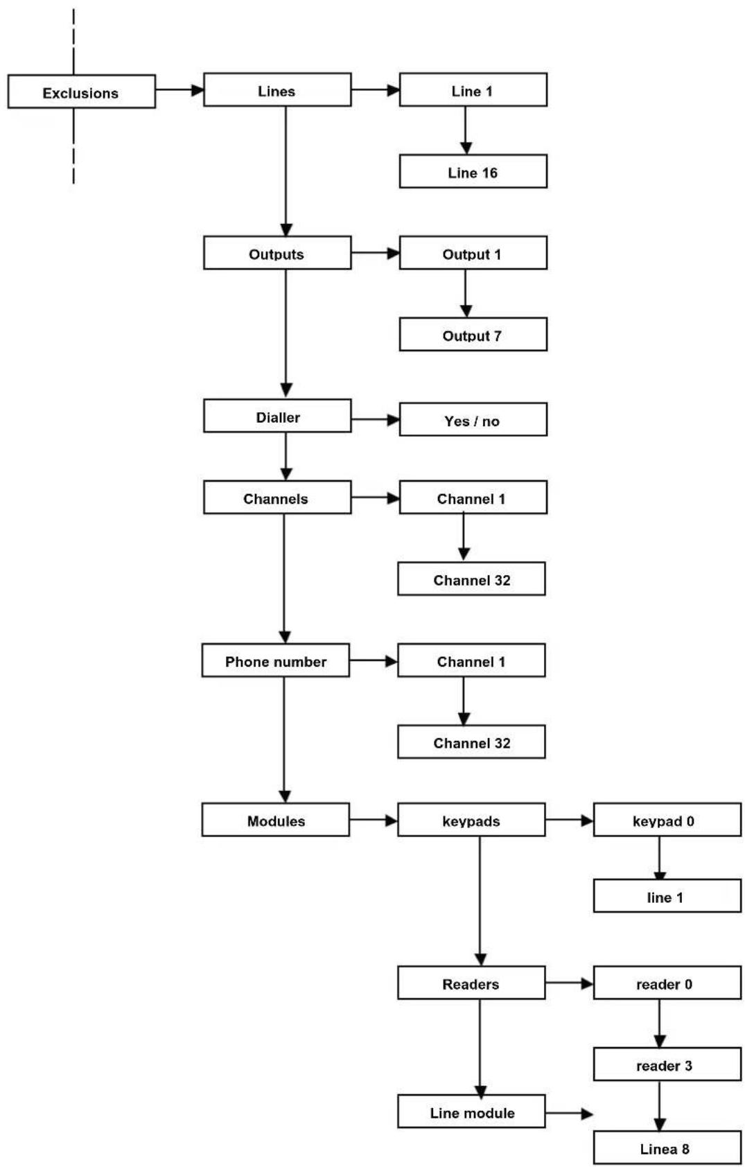
8.7 Exclusions
With the CE2N-416 unit, it is possible to exclude some of the control unit's functional elements, such as lines or outputs for eliminating possible malfunctioning. The control unit ignores an excluded component; therefore, it is possible to neither receive alarms from an excluded line nor activate the excluded outputs.
flowchart
graph TD
    A["Exclusions"] --> B["Lines"]
    B --> C["Line 1"]
    C --> D["Line 16"]
    B --> E["Outputs"]
    E --> F["Output 1"]
    F --> G["Output 7"]
    E --> H["Dialler"]
    H --> I["Yes / no"]
    E --> J["Channels"]
    J --> K["Channel 1"]
    K --> L["Channel 32"]
    J --> M["Phone number"]
    M --> N["Channels 1"]
    N --> O["Channel 32"]
    M --> P["Modules"]
    P --> Q["keypads"]
    Q --> R["keypad 0"]
    R --> S["line 1"]
    Q --> T["Readers"]
    T --> U["reader 0"]
    U --> V["reader 3"]
    V --> W["Line module"]
    W --> X["Linea 8"]
ATTENTION: if a line is excluded manually or if it is being TESTED and the system is COMPLETELY armed, the CHBUS will display the LED green permanently on (all armed) while the keypad will display the indication of the zone/s excluded and, even if the control unit is compétely armed, the system will display the words "CENTRALE PARTE INSERITA". The event log will record the exclusion of the zone/s and, if the system is completely armed with one excluded zone, the words "TOTAL ACTIVATION" will be displayed.
In the event of a failure and/or anomaly of a module connected to the BUS, the control unit will automatically exclude the failed module.
9 RESET
The procedures can be performed from the keypad by the keys RESET, DEFAULT. Two procedures are possible:
- Keypad reset with a zero address
- Restore of factory settings
text_image
J800 J200 SSO0 RESET LINE LA LB PHONE DA DB GND + J801 J1 +13.8V GND S1 TAMFER J2 OFF ON S2 OUT 1 OUT 2 OUT 3 OUT 4 OUT 5 OUT 6 OUT 7 OUT 8 OUT 9 OUT 10 OUT 11 OUT 12 OUT 13 OUT 14 OUT 15 OUT 16 OUT 17 OUT 18 OUT 19 OUT 20 OUT 21 OUT 22 OUT 23 OUT 24 OUT 25 OUT 26 OUT 27 OUT 28 OUT 29 OUT 30 OUT 31 OUT 32 OUT 33 OUT 34 OUT 35 OUT 36 OUT 37 OUT 38 OUT 39 OUT 40 OUT 41 OUT 42 OUT 43 OUT 44 OUT 45 OUT 46 OUT 47 OUT 48 OUT 49 OUT 50 OUT 51 OUT 52 OUT 53 OUT 54 OUT 55 OUT 56 OUT 57 OUT 58 OUT 59 OUT 60 OUT 61 OUT 62 OUT 63 OUT 64 OUT 65 OUT 66 OUT 67 OUT 68 OUT 69 OUT 70 OUT 71 OUT 72 OUT 73 OUT 74 OUT 75 OUT 76 OUT 77 OUT 78 OUT 79 OUT 80 OUT 81 OUT 82 OUT 83 OUT 84 OUT 85 OUT 86 OUT 87 OUT 88 OUT 89 OUT 90 OUT 91 OUT 92 OUT 93 OUT 94 OUT 95 OUT 96 OUT 97 OUT 98 OUT 99 OUT1009.1 RESET THE KEYPAD SERIAL NUMBER WITH A ZERO ADDRESS
We would like to specify that all the keypads (such as all the bus devices) are identified by the control unit by means of a serial number in the memory of the devices themselves. Therefore, if somebody tries to connect a device to a bus that is not acquired, the system will generate an anomaly. In particular, the keypad with a zero address is the only one that can communicate with the control unit without the control unit having that keypad's serial number in memory. This is possible only if, at that moment, the control unit doesn't have in its memory a keypad with a zero address. The keypad with a zero address allows you to communicate with the control unit during the first installation as well as making the first acquisitions and settings.
ATTENTION : this procedure cancels the serial number and restores the factory setting of the control unit keypad with a 0 address.
The following is the procedure to cancel the serial number of the zero keypad.
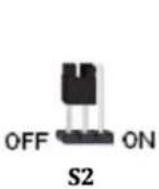
1) Start with the jumper S2 in the OFF position as shown in the figure.
2) Simultaneously press and hold "RESET" and "DEFAULT" for 5 seconds
3) Keep the "DEFAULT" key pressed and release the RESET key. The keypad emits an acoustic signal and displays the words "Factory Default Completed?"
4) Remove the jumper S2
5) The keypad emits an acoustic signal and displays the word "Reset Address?"
4) Release the "DEFAULT" key
The keypad displays the words "Reset Address - Keypad no. 00"
5) Reposition the Jumper S2's connection as before the procedure
The control unit will reboot the system.
9.2 RESTORE FACTORY SETTINGS
This procedure cancels all the settings made during the programming and it restores the factory settings. The following is the procedure to restore the factory settings:
1) Start with the jumper S2 in the OFF position as shown in the figure.

2) Simultaneously press and hold the "RESET" and "DEFAULT" keys for 5 seconds.
3) Keep the "DEFAULT" key pressed and release the RESET key. The keypad emits an acoustic signal and displays the words "Factory Default Completed?"
5) Release the "DEFAULT" key"; the keypad emits an acoustic signalization and displays the words "FACTORY DEFAULT in progress...."
Now the control unit will reboot the system.
ATTENTION: if the control unit FIRMWARE must be updated, check the availability of an update from the website www.fracarro.com in the section "Software updating"; the folder contains the instructions to update the control unit.
10 USER MANUAL
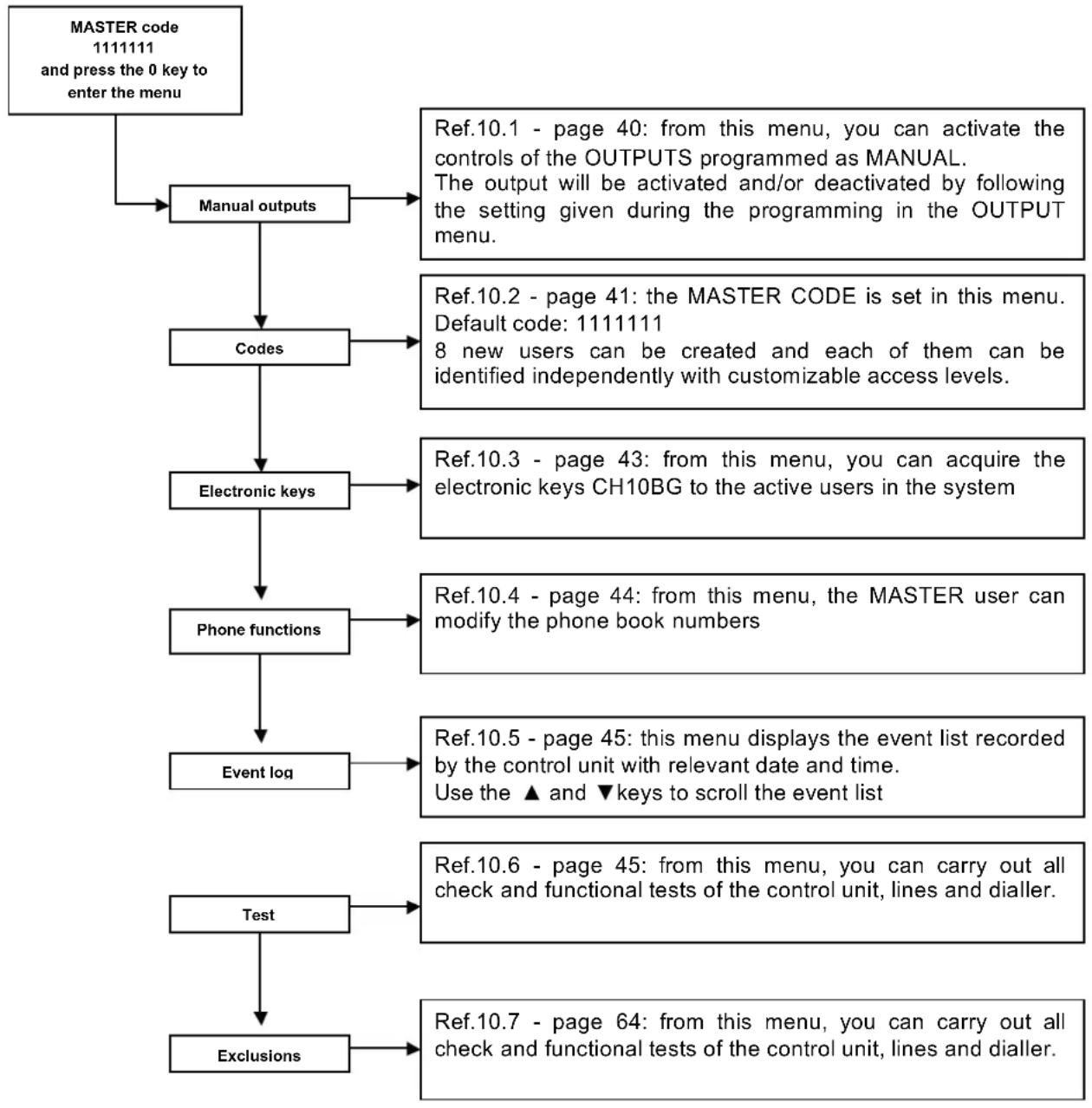
flowchart
graph TD
    A["MASTER code\n1111111 and press the 0 key to enter the menu"] --> B["Manual outputs"]
    B --> C["Codes"]
    C --> D["Electronic keys"]
    D --> E["Phone functions"]
    E --> F["Event log"]
    F --> G["Test"]
    G --> H["Exclusions"]
    B --> I["Ref.10.1 - page 40: from this menu, you can activate the controls of the OUTPUTS programmed as MANUAL.\nThe output will be activated and/or deactivated by following the setting given during the programming in the OUTPUT menu."]
    C --> J["Ref.10.2 - page 41: the MASTER CODE is set in this menu.\nDefault code: 1111111\n8 new users can be created and each of them can be identified independently with customizable access levels."]
    D --> K["Ref.10.3 - page 43: from this menu, you can acquire the electronic keys CH10BG to the active users in the system"]
    E --> L["Ref.10.4 - page 44: from this menu, the MASTER user can modify the phone book numbers"]
    F --> M["Ref.10.5 - page 45: this menu displays the event list recorded by the control unit with relevant date and time.\nUse the ▲ and ▼ keys to scroll the event list"]
    G --> N["Ref.10.6 - page 45: from this menu, you can carry out all check and functional tests of the control unit, lines and dialler."]
    H --> O["Ref.10.7 - page 64: from this menu, you can carry out all check and functional tests of the control unit, lines and dialler."]
10.1 Manual outputs:
This menu allows you to activate a control unit output (after entering the user code and pressing the "0" key).
This function is used to control directly the external lights, plants and irrigation systems, additional signalizations, etc. from the keypad.
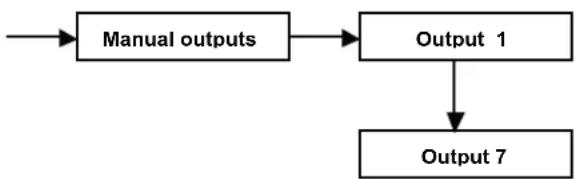
flowchart
graph TD
    A["Manual outputs"] --> B["Output 1"]
    B --> C["Output 7"]
- Use the arrows to select how many outputs as have been defined before. If the manual outputs of the installer menu were not defined during the programming phase, this option is not valid.
- Press the "V" key to turn the symbol besides the output name from "S" in "A" and, therefore, the chosen output is activated. To change the output status, press the "V" key again.
10.2 Codes
This function allows for the management of the codes, which must be operative for managing the system.
From this menu, you can manage the different functionalities of all the system codes. This submenu is available from the master user menu.
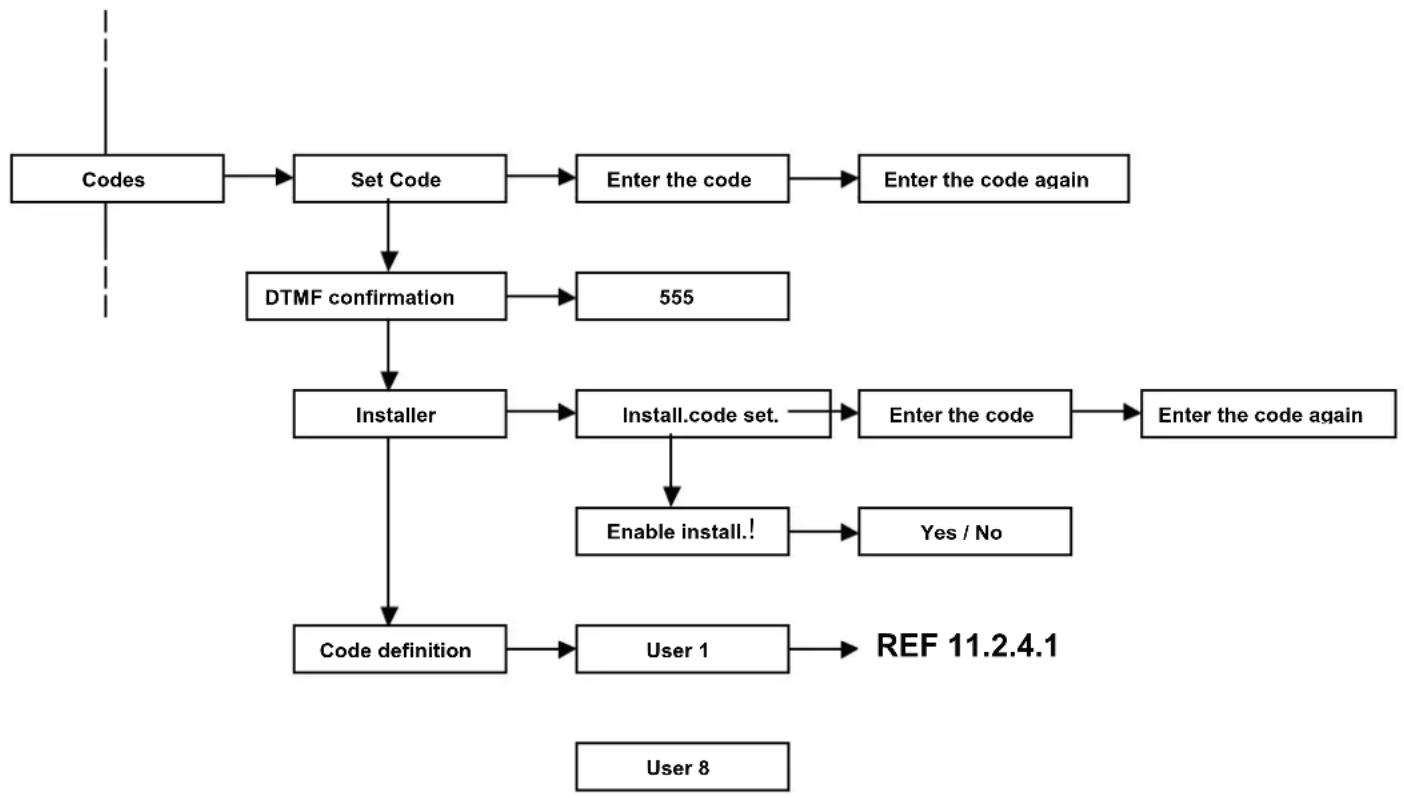
flowchart
graph TD
    A["Codes"] --> B["Set Code"]
    B --> C["Enter the code"]
    C --> D["Enter the code again"]
    B --> E["DTMF confirmation"]
    E --> F["555"]
    F --> G["Installer"]
    G --> H["Install.code set."]
    H --> I["Enter the code"]
    I --> J["Enter the code again"]
    G --> K["Enable install.!"]
    K --> L["Yes / No"]
    G --> M["Code definition"]
    M --> N["User 1"]
    N --> O["REF 11.2.4.1"]
    P["User 8"] --> M
Set Code
With this function, the MASTER user customizes his/her code.
The code must be entered twice to confirm the entered sequence of digits
DTMF confirmation
With this function, the MASTER user customizes his/her block code for the incoming alarm phone calls.
When the call is received from the dialler, the user enters the confirmation code on the phone keypad (by default 555);
in accordance with the programmed phone options, the control unit will do the following:
- When the Total Block is set in the dialler menu to NO: the dialler will stop the call repetition to the user's phone, but it will continue to call all the other numbers in the phone book associated with the channel.
- When the Total Block is set in the dialler menu to YES: the dialler will block the whole sequence of calls and will not send any calls to the other numbers in the phone book associated with the channel.
Installer
Set Installer code: With this function, the MASTER user can restore the programming code of the installer, if it is needed.
The code must be entered twice to confirm the entered sequence of digits.
Enable installer: With this function, the MASTER user can disable the installer code.
This way, the whole installer's menu and the possibilities to modify the programming will be blocked.
Code definition
With this function, the MASTER user creates and customizes the new codes that will have different operating functions.
Enter the submenus to define the code powers.
It can be defined what the code can activate and deactivate, which partition it can activate or deactivate and which areas of the houses it can exclude.
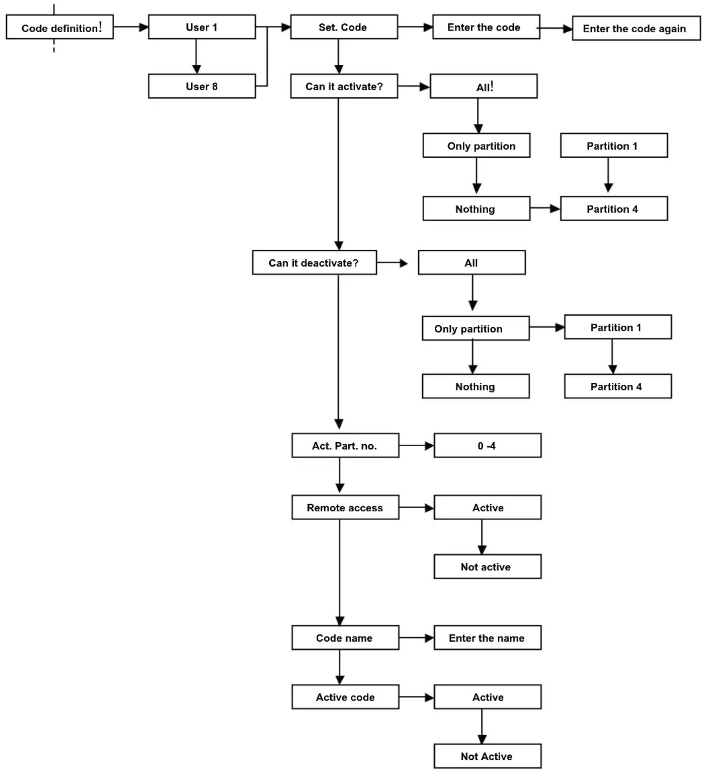
flowchart
graph TD
    A["Code definition!"] --> B["User 1"]
    B --> C["User 8"]
    C --> D["Set. Code"]
    D --> E["Can it activate?"]
    E --> F["Can it deactivate?"]
    F --> G["Act. Part. no."]
    G --> H["Remote access"]
    H --> I["Code name"]
    I --> J["Active code"]
    J --> K["Active"]
    K --> L["Not Active"]
    D --> M["Enter the code"]
    M --> N["Enter the code again"]
    F --> O["All!"]
    O --> P["Only partition"]
    P --> Q["Nothing"]
    Q --> R["Partition 4"]
    R --> S["Partition 1"]
    S --> T["Partition 1"]
    T --> U["Partition 4"]
    G --> V["0 -4"]
    V --> W["Active"]
    W --> X["Not active"]
    I --> Y["Enter the name"]
Set the code: With this function, the MASTER user generates a new user code. The code must be entered twice to confirm the sequence of entered digits
Can it activate? With this function, the MASTER user defines the insertion characteristics of this code.
• ALL: the code is enabled to the TOTAL switching on and all the PARTS are active
- ONLY PARTS: the code can activate only one part of the system (for example: enable the gardener to activate the external area and the equipment storage room, but he can't activate the house); only the associated part must be chosen
• NOTHING: the code is disabled to any activation
Can it deactivate? With this function, the MASTER user defines the deactivation characteristics of this code.
• ALL: the code is enabled to the TOTAL switching off and all the PARTS are active
- ONLY PARTS: the code can deactivate only one part of the system (for example: enable the gardener to deactivate the external area and the equipment storage room but he can't deactivate the house); only the associated part must be chosen
• NOTHING: the code is disabled to any deactivation
Partial activation number With this function, the MASTER user defines how many partial activations the generated user can manage
Remote access: With this function, the MASTER user defines if the user code is enabled for all its functions to manage the system remotely via telephone.
Code name: With this function, the MASTER user identifies the user with a specific name; this function makes the system management more intuitive
Active code: With this function, the MASTER user blocks or activates the functionalities of the code in the system without cancelling the characteristics of the generated code.
10.3 Electronic keys
The system can be managed by the keypad and the electronic key. The electronic keys of the CE2N-416 control unit have the same power of the codes they are associated to.
Each key is associated to a user code and it allows the total activation and the partial activation (maximum 4) which are programmed for the user and more keys can be associated to the same code.
The cancellation with electronic key is for the all associated code.
The diagram below shows the acquisition or cancellation procedure of the electronic keys.
The keys can be associated to the Master or to a user code and they will acquire all the characteristics of the code itself.
The CE2N-416 control unit can have maximum of 16 CH10BG keys.
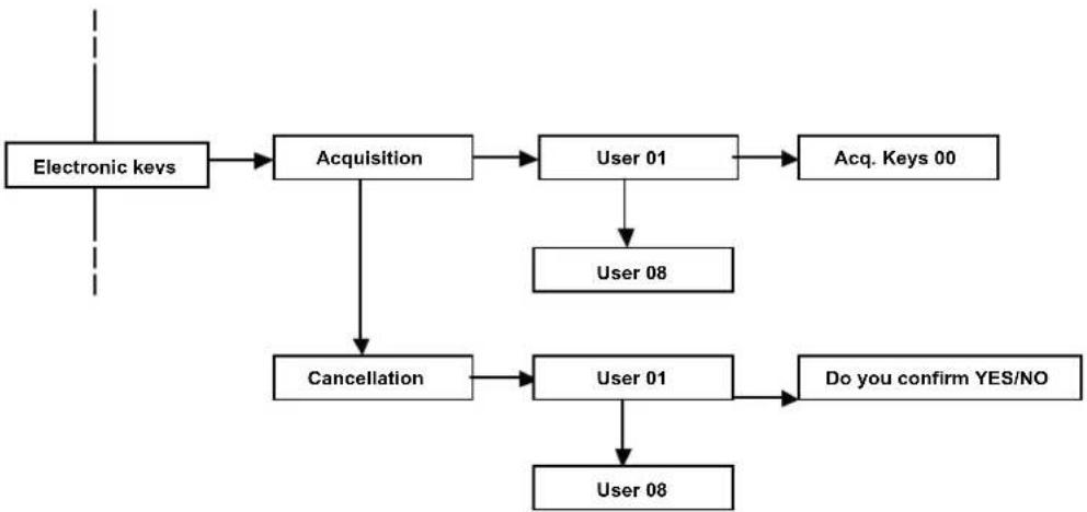
flowchart
graph TD
    A["Electronic keys"] --> B["Acquisition"]
    B --> C["User 01"]
    C --> D["Acq. Keys 00"]
    B --> E["Cancellation"]
    E --> F["User 01"]
    F --> G["Do you confirm YES/NO"]
    F --> H["User 08"]
- Acquisition: With this function, the electronic keys are configured.
- Select the user and confirm with the "V" key
• The display shows how many keys were acquired to this user (by default 00) - Three LEDs (red, yellow and green) will start flashing fast in the readers; this shows that the system is ready to acquire the keys
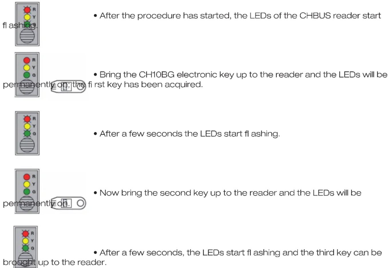
text_image
After the procedure has started, the LEDs of the CHBUS reader start flashing. Bring the CH10BG electronic key up to the reader and the LEDs will be permanently on; the first key has been acquired. After a few seconds the LEDs start flashing. Now bring the second key up to the reader and the LEDs will be permanently on. After a few seconds, the LEDs start flashing and the third key can be brought up to the reader.Continue the sequence for all the keys that you want to memorize.
After all keys are memorized, press "X" to finish the procedure.
Now all keys have been acquired and the alarm system is ready to be activated or deactivated by electronic keys.
ATTENTION: if, in the OTHER menu, the “Continuous display” function of the LEDs is set to “YES,” then the CH10BG electronic keys can be acquired ONLY by the MASTER user; the other users (if configured) won’t be displayed.
- Cancellation: With this function, all the electronic keys of the user are cancelled.
ATTENTION: when the keys linked to the user are cancelled, ALL the other keys associated to that user will be cancelled.
10.4 Telephone functions
With this function, the MASTER user can modify the numbers in the PHONE BOOK.
Among the functions that can be modified, apart from the phone number, you can modify the associated NAME.
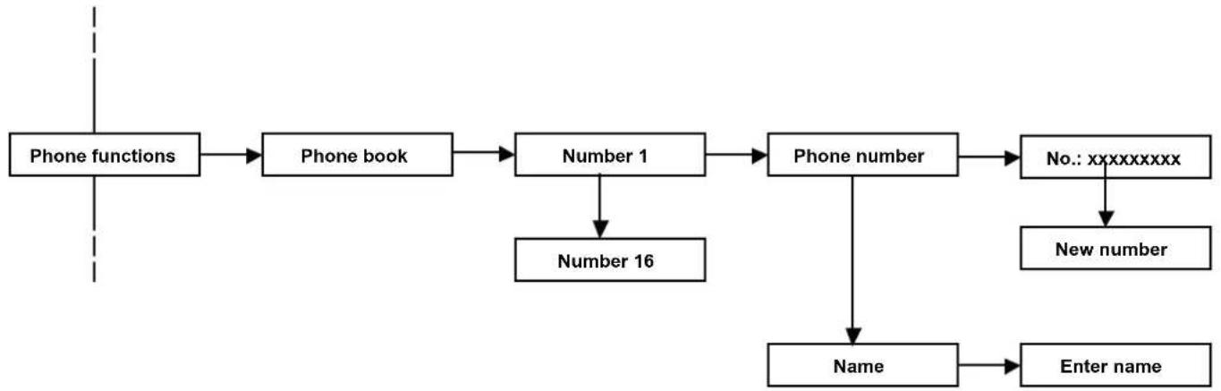
flowchart
graph TD
    A["Phone functions"] --> B["Phone book"]
    B --> C["Number 1"]
    C --> D["Phone number"]
    D --> E["No.: xxxxxxxxx"]
    E --> F["New number"]
    C --> G["Number 16"]
    D --> H["Name"]
    H --> I["Enter name"]
10.5 Historic log
The control unit memorizes permanently up to 250 events with the date and time. All the system events are always visible from any keypad, as well as any control unit anomaly and the accesses of the various users, master and installer.
The following signalizations are added to the dialer when a call is sent:
T= line tone
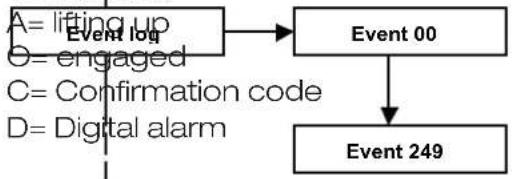
flowchart
graph TD
    A["Event 00"] --> B["Event 249"]
    C["Lifting up Event log"] --> A
    D["Engaged"] --> A
    E["Confirmation code"] --> A
    F["Digital alarm"] --> A
10.6 Test
Specific functions can be used to check the correct operation of the system.
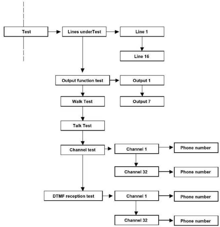
flowchart
graph TD
    A["Test"] --> B["Lines underTest"]
    B --> C["Line 1"]
    C --> D["Line 16"]
    B --> E["Output function test"]
    E --> F["Walk Test"]
    F --> G["Talk Test"]
    G --> H["Channel test"]
    H --> I["DTMF reception test"]
    C --> J["Output 1"]
    J --> K["Output 7"]
    H --> L["Channel 1"]
    L --> M["Phone number"]
    H --> N["Channel 32"]
    N --> O["Phone number"]
    H --> P["Channel 1"]
    P --> Q["Phone number"]
    H --> R["Channel 32"]
    R --> S["Phone number"]
Lines under Test
The CE2N-416 control unit allows you to test the lines without it activating the alarm outputs and the tone signals from the keypads.
Under the test mode, the line is activated according to the programmed modes (for example, a delayed line keeps the input/output time, even when it is being tested).
An alarm on lines being tested is signalled on the keypad display, on the red LED of the keypad and on the key reader. The alarm is recorded in the historic log.
A line being tested generates a self-protection alarm (if the line is configured as single or double balancing).
ATTENTION: if a line is excluded manually or it is being TESTED and the system is COMPLETELY ARMED, the CHBUS reader will show the LED permanently green (all armed), the keypad will display the zone/s excluded even if the system is completely armed and will display the words "CENTRALE PARTE INSERITA". The event log will record the zone exclusion and, if the system is completely armed with one excluded zone, the words "TOTAL ACTIVATION" will be displayed.
Output function test
The CE2N-416 control unit allows the testing of all alarm outputs on the card by activating each of them for about 3 seconds.
Walk test
The control unit allows you to quickly and efficiently check the correct operation of the sensors and modules.
Place the control unit in "line walk test" mode and activate the sensors that you want to control.
The keypad buzzer will generate a tone every time the sensor is activated and the activation will be recorded on the display.
Walk test Tamper
The control unit allows you to quickly and efficiently check the proper operation of the sensor self-protections. Place the control unit in “walk test tamper” mode and open the cases of the sensors that you want to control. The keypad buzzer will generate a tone every time that the contact is activated and the activation will be recorded on the display.
Channel test
The control unit allows the test of the phone alarm channels and the correct dispatch of vocal and/or digital messages to a specific number.
The call is sent without generating an effective alarm.
DTMF reception test
The control unit can test the reception of the DTMF tones.
This test allows you to understand if the CE2N-416 control unit recognizes the DTMF tones sent by the phone line from a phone.
Choose an active channel and an associated phone number; press V to call.
• Answer the incoming call
• NO message will be heard
- Press the various digits 1,2,3,4,5,6,7,8,9,0,*,# from the phone keypad
- From the display of the T8N and/or T8N-Light keypads, the same figures which are pressed on the phone will appear in the same sequence.
If the numbers don't appear, modify the sensitivity of the telephone in the menu
Dialler ▶ Control unit phone options ▶ reception gain
If the problem is not solved, check the connection and/or check the signal quality of the incoming phone line.
10.7 Exclusions
With the CE2N-416 unit, it is possible to exclude some of the control unit's functional elements, such as lines or outputs for eliminating possible malfunctioning.
The control unit ignores an excluded component; therefore, it is possible to neither receive alarms from an excluded line nor activate the excluded outputs.
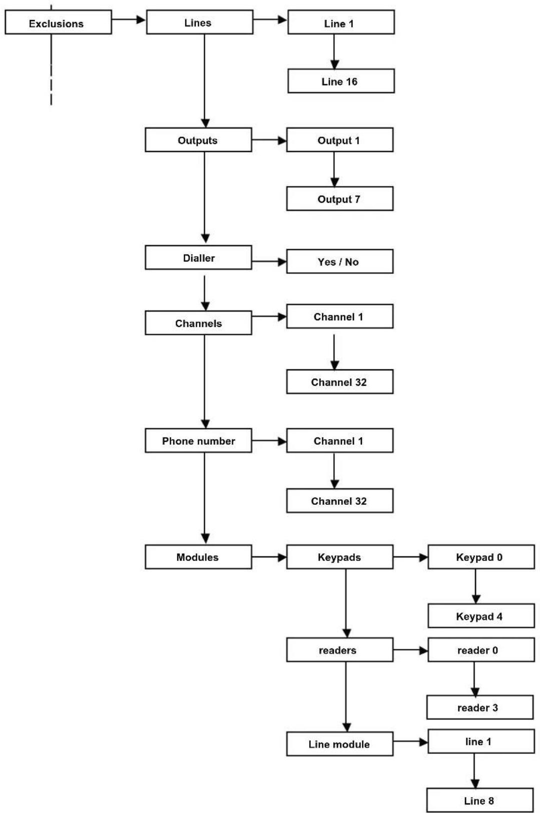
flowchart
graph TD
    A["Exclusions"] --> B["Lines"]
    B --> C["Line 1"]
    C --> D["Line 16"]
    B --> E["Outputs"]
    E --> F["Output 1"]
    F --> G["Output 7"]
    E --> H["Dialler"]
    H --> I["Yes / No"]
    E --> J["Channels"]
    J --> K["Channel 1"]
    K --> L["Channel 32"]
    J --> M["Phone number"]
    M --> N["Channel 1"]
    N --> O["Channel 32"]
    M --> P["Modules"]
    P --> Q["Keypads"]
    Q --> R["Keypad 0"]
    R --> S["Keypad 4"]
    Q --> T["readers"]
    T --> U["reader 0"]
    U --> V["reader 3"]
    T --> W["Line module"]
    W --> X["line 1"]
    X --> Y["Line 8"]
Garantito da/ Guaranteed by/ Garanti par/ Garantizado por/ Garantido por/ Garantiert durch/ Zajamčena od/ Garantirano od/ Garantovano od/ Gwarantowane przez / Εγγυημένο από/ Гарантировано
Fracarro Radioindustrie S.p.A., Via Cazzaro n. 3, 31033 Castelfranco Veneto (Tv) – Italy
Fracarro (UK) - Ltd, Unit A, Ibex House, Keller Close, Kiln Farm, Milton Keynes MK11 3LL UK
Tel: +44(0)1908 571571 - Fax: +44(0)1908 571570