T6.354MGT - Marine engine Perkins - Free user manual and instructions
Find the device manual for free T6.354MGT Perkins in PDF.

| Product Type | Marine Diesel Engine |
| Model | T6.354MGT |
| Brand | Perkins |
| Configuration | Inline 6-cylinder |
| Displacement | 5.8 L (354 cu in) |
| Induction | Turbocharged |
| Fuel Type | Diesel |
| Power Output | 120–150 hp (at rated RPM) |
| Cooling System | Heat exchanger, freshwater cooled |
| Weight (approx) | 650 kg (1,433 lb) |
| Dimensions (L x W x H) | 1200 x 700 x 800 mm (approx) |
| Oil Capacity | 12 L (with filter change) |
| Coolant Capacity | 15 L |
| Recommended Oil | SAE 15W-40 (API CH-4 or higher) |
| Maintenance Interval | Oil and filter change every 250 hours |
| Fuel System | Direct injection with mechanical or electronic governor |
| Starting System | Electric start (12V or 24V) |
| Emissions Compliance | IMO Tier II (typical for age) |
| Safety Features | Low oil pressure alarm, high coolant temp alarm |
| Cleaning | Keep engine clean; use degreaser on external surfaces |
| Spare Parts Availability | Widely available through Perkins dealers |
Frequently Asked Questions - T6.354MGT Perkins
User questions about T6.354MGT Perkins
0 question about this device. Answer the ones you know or ask your own.
Ask a new question about this device
Download the instructions for your Marine engine in PDF format for free! Find your manual T6.354MGT - Perkins and take your electronic device back in hand. On this page are published all the documents necessary for the use of your device. T6.354MGT by Perkins.
USER MANUAL T6.354MGT Perkins
OPERATORS MANUAL FOR
MARINE DIESEL ENGINES
4.108
6.354
T6.354MGT
4.154
T6.354
V8.510
4.236
HT6.354
TV8.510
This handbook is an adaptation of the original Marine Engine Operators Manual produced by the Service Publications Department of Perkins Engines Ltd., Peterborough, England. Every endeavor has been made to ensure that the information contained within this handbook is correct at the date of publication but, because of continuous developments, Perkins Engines reserves the right to alter the contents without notice.
HANDBOOK FOR MARINE DIESEL ENGINES

U.S.A.: 32500 Van Born Road Wayne, Michigan 48184 Phone: 313/493-8500
CANADA: 7 Meridian Road Rexdale, Ontario M9W 4Z6 Phone: 416/675-3540
Published: 1978 Publication Number: 201 SER 1068A © Perkins Engines, Inc. 1978
This marine handbook is general in content and encompasses the whole range of current Perkins marine engines that are marketed in North America. Workshop manuals involving the overhaul of Perkins engines and relevant gearboxes are available, if required, from any Perkins Marine Distributor.
This handbook is distributed to provide guidance for correctly operating and maintaining Perkins marine diesel engines. If correctly installed, correctly operated and correctly maintained, a Perkins diesel engine will provide its owner with years of dependable service. This handbook also includes information relating to Marine propulsion, trouble-shooting and performing minor engine repairs while afloat.
PERKINS PARTS FOR PERKINS PRODUCTS
To ensure you obtain the best results from your engine and to safeguard your warranty, install only genuine Perkins parts. These are readily obtainable throughout the world.
Table of Contents
INTRODUCTION 4
ENGINE IDENTIFICATION 7
ENGINE PHOTOGRAPHS 12
ENGINE SPECIFICATIONS 28
INSTRUMENTS 30
STARTING AND STOPPING ENGINE 31
SCHEDULED MAINTENANCE....34
ENGINE PRESERVATION 42
COLDWEATHER PRECAUTIONS 45
FUEL SYSTEM 45
COOLING SYSTEM 54
LUBRICATING SYSTEM 56
LUBRICATING OIL SPECIFICATIONS ....58
GEARBOXES (TRANSMISSIONS) 59
CHECKING VALVE TIP CLEARANCES 61
Perkins Engines, Inc. (hereinafter called Perkins) warrants each new engine sold under the trademark "Perkins," and operated in the United States of America or Canada to power marine applications to the first retail purchaser thereof for a period of 12 months or 1,800 hours, whichever event shall first occur, to be free from defects in workmanship and material from the date of delivery to such purchaser.
2. REPLACEMENT OF PARTS UNDER WARRANTY
The responsibility of Perkins is limited to repairing or replacing, at its option, any part or parts of such engines that are returned to Perkins or any authorized Perkins distributor or dealer, with transportation charges prepaid, and which upon examination by Perkins shall disclose to Perkins' satisfaction to have been thus defective.
3. PAYMENT OF REPAIR LABOR COST UNDER WARRANTY
During the first 12 months or 1,800 hours of engine operation, whichever event shall occur first, from the date of delivery to the first purchaser, Perkins or any authorized Perkins distributor or dealer will cover the cost of reasonable labor required to repair any engine or replace any parts found by Perkins to be defective.
- Perkins' obligation under this Warranty shall not apply to: (a) Starters, Alternators, Transmissions, Clutches, Radiators, or any other proprietary fittings not manufactured by Perkins. These are warranted by their respective manufacturers and not by Perkins. (b) Any engine which shall have been subject to negligence, misuse, accident, misapplication or overspeeding. (c) Any engine that has been repaired or altered by anyone in a manner which in Perkins' sole judgement adversely affects its performance or reliability. (d) Any engine which has been fitted with or repaired
with parts or components not manufactured or approved by Perkins which in Perkins' sole judgement adversely affect its performance or reliability. (e) Engine tune-ups, normal maintenance services including but not limited to valve adjustment, normal replacement of service items, fuel and lubricating oil filters, lubricating oil, fan belts, antifreeze, etc. (f) Damages caused by prolonged or improper storage of the engine after shipment from a Perkins factory. (g) Loss of operating time to the user while the engine or engine driven equipment is out of operation, and damage to equipment powered by this engine.
- This warranty and the obligation of Perkins Engines, Inc. here-under is in lieu of all other express warranties including, without limitations, all other representations to the purchaser. Any implied warranties, including any warranty of merchantability or fitness for a particular purpose, are expressly limited to the duration of this written warranty. In no event shall the purchaser be entitled to recover for incidental or consequential damages. Some states do not allow limitations on how long an implied warranty lasts, so the above limitation may not apply to you. Some states do not allow the exclusion or limitation of incidental or consequential damages, so the above limitation or exclusion may not apply to you. This warranty gives you specific legal rights, and you may also have other rights which vary from state to state.
SPECIAL NOTE
Perkins engines are marketed throughout the world to many manufacturers of original equipment. In order to meet the special requirements of these, engines may on occasion be covered by specific warranties applicable to the requirements of the driven equipment. In these instances the warranty extended by Perkins to said manufacturer supersedes the above warranty.
ENGINE IDENTIFICATION
Each Perkins engine is identified by means of an identification code (see page 7). To ensure prompt, efficient results when ordering parts, requesting repairs or information, record the identification code in the space provided below so that it will be available when needed.
Engine Identification Code:
INTRODUCTION
Dependable performance can be expected from a Perkins marine diesel engine when the operation and maintenance procedures are based upon a clear understanding of diesel engine operating principles. Each moving part of the engine affects the operation of every other moving part and the engine as a whole.
Perkins diesel engines are four stroke cycle engines with either a direct or indirect combustion system. Diesel engines differ from other internal combustion engines in several ways. Compression ratios are higher than in gasoline engines. The intake stroke provides air only to the cylinder. Fuel is delivered to the cylinder in an atomized form by an injector. This fuel, in accurately metered quantities and with exact timing, is delivered to the injectors via extremely high pressure from the fuel injection pump. Ignition of the fuel is effected by the heat developed from compressing the air into the combustion chamber.
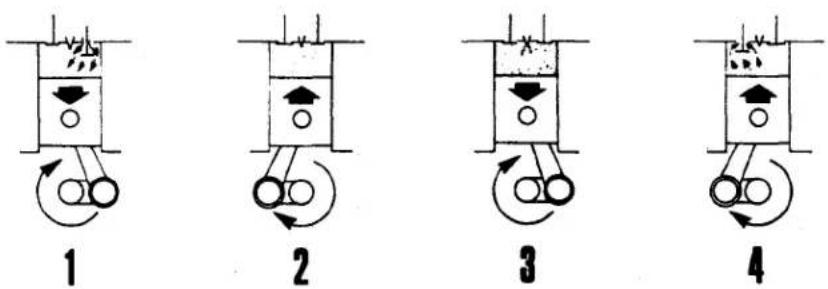
PERKINS DIESEL FOUR STROKE CYCLE
- INTAKE STROKE - The piston travels down the cylinder, the intake valve is open and the exhaust valve is closed. The partial vacuum created by the downward stroke of the piston pulls air from outside through the open intake valve into the cylinder.
- COMPRESSION STROKE - At the end of the intake stroke, the intake valve closes while the piston travels upward on the compression stroke. The exhaust valve remains closed. At the end of the compression stroke, the air in the combustion chamber has been forced by the piston into a space that is one-sixteenth (or less) the original volume available at the beginning of the stroke. Thus, the compression ratio is 16:1 (or, for some engines, greater).
Compressing the air into a small space causes the temperature to rise to approximately 1000 degrees F. Just before T.D.C., a small atomized, metered charge of fuel is injected into the combustion chamber, the fuel is ignited by the hot air and starts to burn. - POWER STROKE - During the power stroke, the piston travels down the cylinder and both intake and exhaust valves are closed. As the air and fuel mixture burns, the gases become hotter and hotter, rapidly expand and add force to crankshaft rotation.
- EXHAUST STROKE - During the exhaust stroke, the intake valve remains closed, the exhaust valve is open, and the piston on the upward stroke forces the burned gases out of the combustion chamber through the open exhaust valve port.
Turbocharged engines utilize the exhaust to power the turbine and "boost" the density of the intake air, which results in an increase in engine power.
The standard direction of rotation for Perkins marine diesel engines is counterclockwise when viewing the engine from the gearbox end (rear) of the engine. Contrarotating engines (rotation is clockwise when viewing the engine from the rear) are the exception.
Perkins marine engines are manufactured to meet all general marine requirements and to be compatible with specific applications. The engines depicted on pages 12 through 27 do not necessarily typify all the various marine engines in use worldwide.
Safety Precautions:
Disregarding fundamental safety rules and precautions may result in injuries to persons coming into contact with or located near an engine. Care should be exercised at all times, particularly in the following respects:
- The coolant in an operating or recently stopped engine is very hot and under pressure. If the filler pressure cap is suddenly removed the liquid may spurt and cause injury by scalding. Always stop an engine and allow it to cool before removing the cap. Once cool, loosen the cap slowly to relieve the pressure.
- External assemblies and accessories driven by an engine, such as the pulleys, belts, and alternator/generator, are hazardous to anyone attempting to repair or service it while it is operating. If possible, always stop an engine before servicing it. When necessary to repair or adjust an operating engine, use extreme caution and do not wear loose clothing.
- The direction of engine rotation and the rotation of any attached or auxiliary drive device are not always the same. The rotation direction of the output shaft should be determined before attaching any auxiliary mechanism that is to be driven by the engine. Failure to consider the respective rotations could result in an unexpected rotation of the mechanism and cause injury.
- Use extraordinary care when hoisting an engine. Ensure that the hoist is correctly arranged and correctly attached to the engine. Failure to do so may result in fracture of the lifting brackets or other mishap.
- Stop the engine before refueling it.

Look for this symbol - it means: ATTENTION! BECOME ALERT! YOUR SAFETY IS INVOLVED! HEED THE INSTRUCTIONS!
Because of the variety of engine applications and their respective uses, it is not possible to anticipate and provide safety precautions for all the potentially hazardous situations that may be encountered during the servicing and operation of a marine engine. In respect to this, each person involved with service and operation should be alert and safety conscious at all times.
ENGINE IDENTIFICATION LOCATION
A. V8.510, TV8.510
B. 4.108, 6.354, T6.354
HT6.354, T6.354 MGT
C. 4.236
D. 4.154
E. 4.154 (Newer Engines)
4.236 (Newer Engines)
A. Top-Front Cyl. Block, R.H. Cyl.Bank
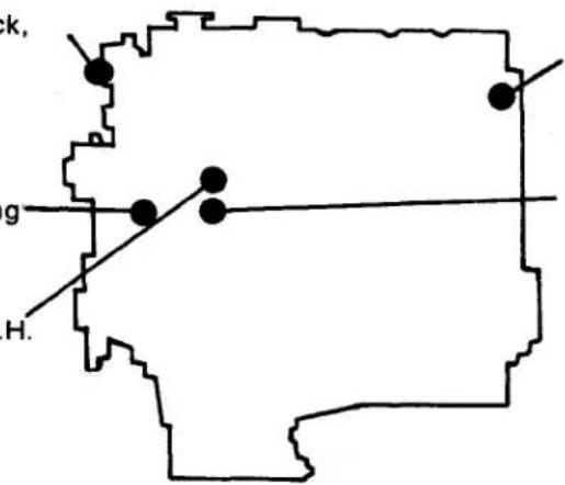
D. Rear-Top Cyl. Block, L.H.
E. Front Cyl. Block, L.H.
B. Fuel Pump Mounting Flange, L.H.
C. Front Cyl. Block, R.H.
"R.H."= Right Hand or Alternator Side
"L.H." = Left Hand, Fuel Injection, Pump Side
Note:
Left and right hand locations are given assuming that the engine is viewed from the rear.
ENGINE IDENTIFICATION
This handbook is applicable to the following marine engine type designations:
4.108 (M)
4.154 (M)
4.236 (M)
6.354 (M)
T6.354 (M)
T6.354 (MGT) ^*
HT6.354 (M)
V8.510 (M)
TV8.510 (M)
The first numeral (e.g., 4) in the engine designation denotes the number of cylinders, while the second group of numerals (e.g., 108) denotes the cubic inch displacement (C.I.D.) of the engine. The prefix letters (e.g., T) denote the following:
T - Turbocharged Engine
H - Horizontally Inclined Engine
V - Two banks of cylinders in "V" formation.
*Special version of the T6.354 Marine engine.
The letter "M" in parenthesis indicates the applicable engine was manufactured specifically for marine applications.
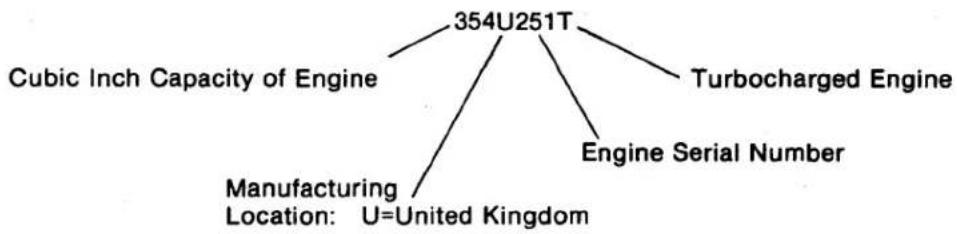
Apart from physical differences, each engine can be identified by the engine identification code stamped into the cylinder block. The code is comprised of a combination of numerals and letters (Alphanumeric). At the present time, two identification formats are in existence. The earlier format (e.g., 354U251T) represents the following data:
flowchart
graph TD
    A["354U251T"] --> B["Cubic Inch Capacity of Engine"]
    A --> C["Turbocharged Engine"]
    A --> D["Engine Serial Number"]
    A --> E["Manufacturing Location: U=United Kingdom"]
In addition to the above, contra-rotating (clockwise) engines are further identified by the letter "X" stamped immediately after the manufacturing location code letter (e.g., 354UX252T).
Additional suffix letters may also be included in the code for certain engines. For example:
H - Horizontally Inclined Engine
L - Lip Type Rear Main Bearing Seal
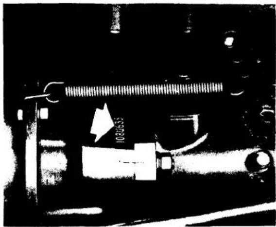
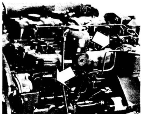
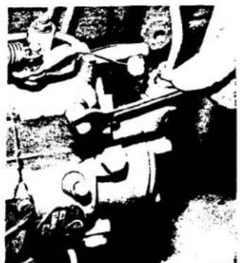
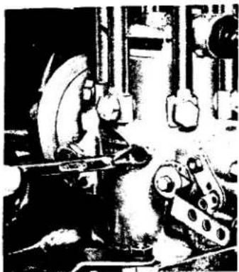
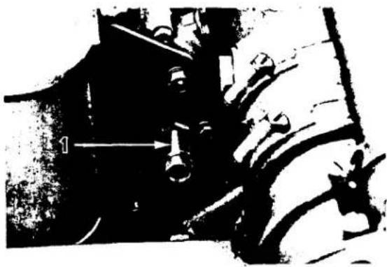
The location of the identification code, as applicable to each engine, is depicted in the following series of illustrations (fig. 2a through fig. 2e). When information, replacement parts or assistance is required, the complete engine identification code should always be quoted.
natural_image
Mechanical assembly diagram showing a spring-loaded component with a bolt and lever (no text or symbols)Fig. 2 (a)
Engine Identification Location 4.108
natural_image
Interior view of an automotive engine bay with visible structural components and no readable text or symbolsFig. 2 (b)
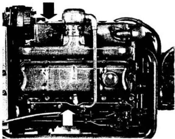
4.154 Engine Identification Location. Rear-Top of Cylinder Block, Left-Hand Side of Engine. Newer Engines: Left-Hand Side of Engine, above fuel injection pump.
natural_image
Interior view of a mechanical engine assembly (no visible text or labels)Fig. 2 (c)
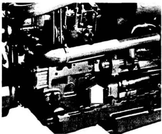
4.236 Engine Identification Location. Machined Pad Immediately Above and Aft of Alternator, Right-Hand Side of Engine. Newer Engines: Left-Hand Side of Engine, above Fuel Injection Pump.
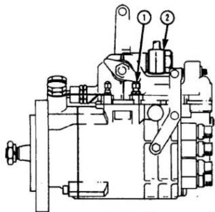
natural_image
Black-and-white photo of a vintage mechanical device with visible gears and components (no text or symbols)Fig. 2 (d)
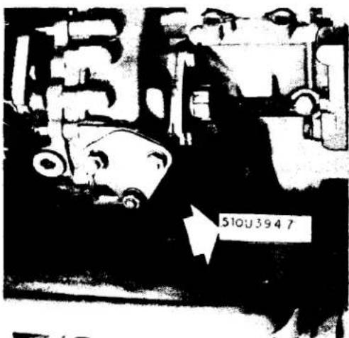
6.354, T6.354, HT6.354, and T6.354MGT Engine Identification Location. Fuel Injection Pump Mounting Flange, Left-Hand Side of Engine.
7
2
2
1
2
Fig. 2 (e)
V8.510 and TV8.510 Engine Identification Location. Top-Front of Cylinder Block, Right-Hand Cylinder Bank.
-9-
NEW FORMAT
The new format for engine identification will be incorporated by all Perkins manufacturing operations in the near future. At the present time, engines produced in England, Germany, Mexico, and the United States are being identified according to the new format. As with its predecessor, the identification of each engine is accomplished via an alphanumeric code, which can be comprised of up to 15 characters (if a secondary parts list reference is required, six additional characters will be used). The standardized location for each engine's identification is a machined pad situated near the fuel injection pump (left side of engine when viewing from rear). Exceptions to this location may arise for certain engines. The following data is represented in sequence by the alphanumeric identification code characters.
DATA
-
Engine Family
-
Engine Type/Phase
-
Parts List (Or Standard Option Scheme Order) Reference*
-
Country of Origin
-
Production (Or Rebuild) Serial Number
-
Year of Manufacture
CHARACTERS
One Alphabetic Letter
One Alphabetic Letter
Five Numerals (Or Letter "A" and Four Numerals)
One Alphabetic Letter
Maximum of Six Numerals (Or Letter "R" and Maximum of Five Numerals)
One Alphabetic Letter
EXAMPLE:
TE22282N1256C
*Certain engines may also have a secondary parts list reference stamped immediately below the primary parts list reference.
EXAMPLE:
TE20696U501376C
NAP12N
Engine Family and Type/Phase Code Interpretations:
The first two characters of the identification code will always be letters. The first letter represents the engine family and the second represents the engine type/phase. The following interpretation are applicable to engine identification codes.
| FAMILY | TYPE | CODE |
| 4.108 | E | |
| 4.99 | EA | |
| 4.107 | EB | |
| T4.107 | EC | |
| 4.108 | ED | |
| 4.154 | G | |
| 4.154 | GA | |
| 4.236 | L | |
| 4.236 | LD |
| FAMILY | TYPE | CODE |
| 6.354 | T | |
| 6.354 | TC | |
| H6.354 | TD | |
| T6.354 | TE | |
| HT6.354 | TF | |
| 6.3541 | TG | |
| T6.3541 | TH | |
| 6.3542 | TJ | |
| H6.3543 | TN | |
| HT6.3543 | TQ | |
| T6.3544 | TU | |
| 6.3544 | TW |
| FAMILY | TYPE | CODE |
| V8.510 | X | |
| V8.510 | XA | |
| TV8.510 | XB |
Parts List References:
Following the first two characters (engine family and type/phase code letters) will be either a group of five numerals or the letter "A" followed by a group of four numerals. If five numerals are used, they will be the reference for the engine build parts list. When an engine is built to a Standard Option Scheme (S.O.S.) order, the reference for the order is comprised of the letter "A" and the last four digits of the order number. The following are examples of both references:
| PARTS LIST REFERENCE: | 21376 |
| ENGINE IDENTIFICATION CODE: | TR21376U500120C |
| STANDARD OPTION SCHEME | |
| NUMBER: | A018752 |
| STANDARD OPTION SCHEME | |
| ORDER REFERENCE: | A8752 |
| ENGINE IDENTIFICATION CODE: | LDA8752U501234C |
Country of Origin Code Interpretations:
The next character will be a one-letter code that represents the country where the basic engine was produced. The following interpretations are applicable to engine identification codes.
COUNTRY OF ORIGIN
| A......Argentine | G......Greece | S......India |
| B......Brazil | J......Japan | T......Turkey |
| C......Australia | L......Italy | U......United Kingdom |
| D......Germany | *M......Mexico | X......Peru |
| E......Spain | N......U.S.A. | Y......Yugoslavia |
| F......France | P......Poland |
*Motores Perkins S.A., Mexico, started using the new identification format in its infancy and uses the letters "MX" vice "M" as the code for Mexico.
Engine Serial Numbers:
Each engine family (if produced at the specific manufacturing location) will have a separate production serial number series initiated at each manufacturing location. To distinguish the new engine serial numbering from that used previously, Peterborough, United Kingdom will start numbering the first produced engine of each family with 500001. All other manufacturing operations will start with 251. Upon attaining serial number 999999, each series will revert to 251. Serial numbers 1 through 250 will always be reserved for prototype engines by each manufacturing operation.
Each manufacturing operation will group rebuilt engines as one type and serialize them progressively regardless of their respective engine family. The serial numbering will start with 251 and progress through 1000 (if necessary) at each location. The letter "R" will be used as a prefix to denote "Rebuilt Engine". For example:
R417
Year of Manufacture Code Interpretations:
The last character in the engine identification code will be a code letter that represents the calendar year during which the engine was either produced or rebuilt. The following interpretations are applicable to engine identification codes:
| LETTER | YEAR |
| B | 1975 |
| C | 1976 |
| D | 1977 |
| E | 1978 |
| F | 1979 |
NOTE: The letters I,O,Q,R, and Z will not be used to represent the year of manufacture.
ENGINE PHOTOGRAPHS
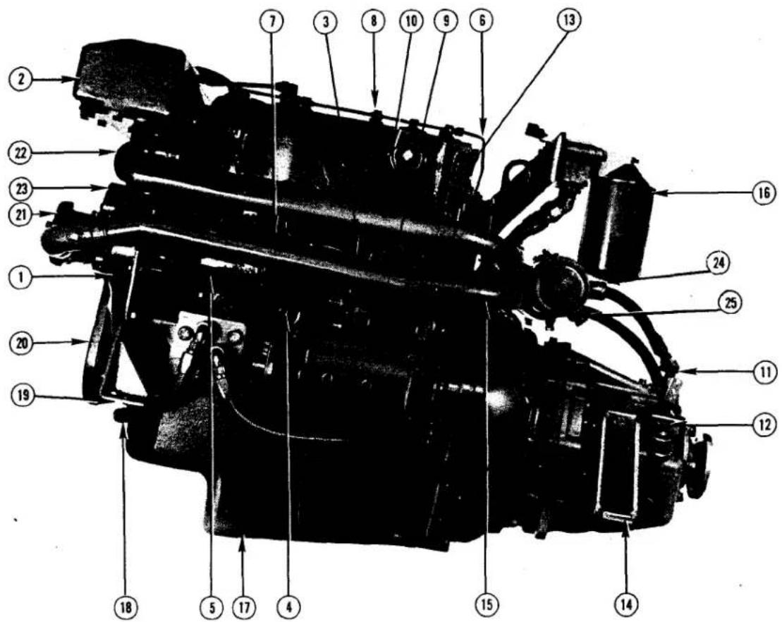
Fig. 3(a) KEY TO 4.108 (M) ENGINE PHOTOGRAPHS
- Timing Case Cover
- Header Tank
- Lub Oil Dipstick
- Lub Oil Pressure Sender
- Fuel Injection Pump
- Injector Leak-Off Pipe
- Pressure Pipes, Injection Pump to injectors
- Injector
- Fuel Pipes, Filter to Injection Pump
- Exhaust Manifold
- Gearbox Forward and Reverse Lever
-
Gearbox Fluid Filler Hole/Dipstick
-
Exhaust Flange
- Rear Engine Support
- Sea Water Pipe, to Sea Water Pump Heat Exchanger
- Lub Oil Filter
- Oil Pan
- Hose from Oil Cooler
- Front Engine Support
- Crankshaft Pulley
- Sea Water Pump
- Fresh Water Pipe, Exhaust Manifold to Heat Exchanger
- Fresh Water Pump
- Sea Water Outlet
- Zinc Anode
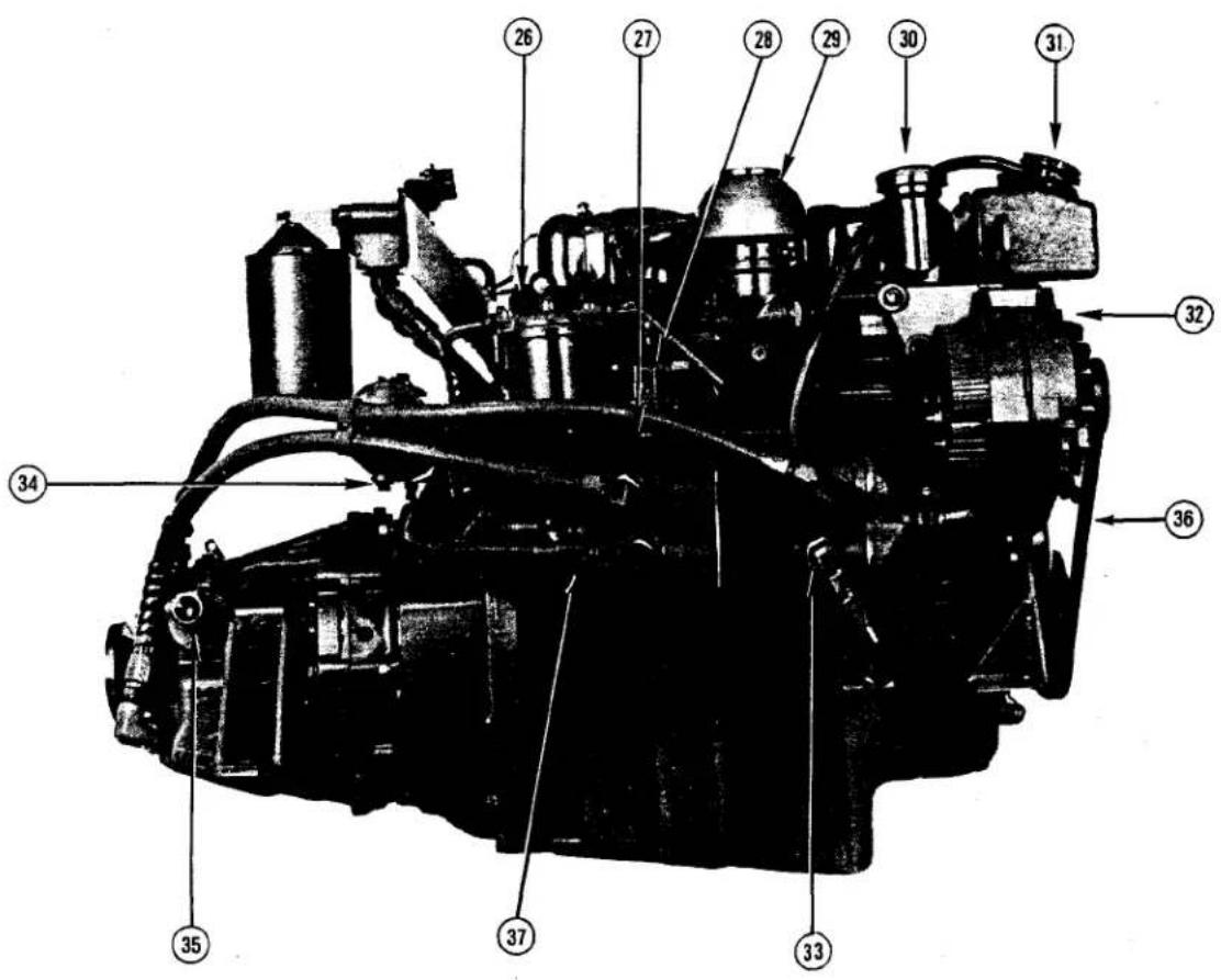
Fig. 3 (b)
- Fuel Filter
- Fuel Transfer Pump Priming Lever
- Fuel Transfer Pump
- Air Filter
- Lub Oil Filler Cap
- Fresh Water Filler Cap
-
Alternator
-
Oil Coolers (Engine and Transmission)
- Heat Exchanger
- Gearbox Neutral Switch
- Alternator/Fresh Water Pump Drive Belt
- Oil Cooler Water Drain
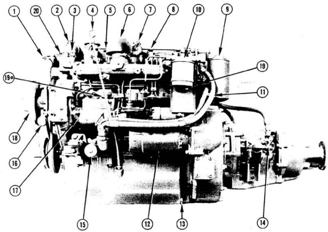
Fig. 3(c) KEY TO 4.154 (M) ENGINE PHOTOGRAPHS
- Sea Water Pipe from Pump to Heat Exchanger
- Fresh Water Pipe from Engine to Heat Exchanger
- Water Temperature Sender
- Lubricating Oil Dipstick
- Lubricating Oil Filler Cap
- Induction Air Filter
- Closed Circuit Breather Pipe
- Injector
- Lubricating Oil Filter
- Fuel Filter
-
Flexible Lubricating Oil Hoses
-
Starter Motor
- Lubricating Oil Pan Drain Plug
- Gear Box Filler and Dipstick
- Engine Lubricating Oil Pressure Sender
- Sea Water Pump Inlet
- Fuel Injection Pump
- Sea Water Pump
- Engine Serial Number (Older Engines)
19a. Engine Serial Number (Newer Engines) - Thermostat Housing and Water Temperature Sender
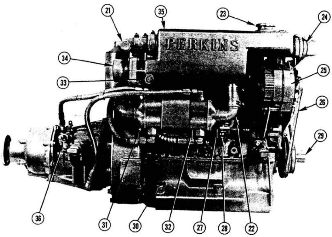
Fig. 3(d)
- Sea Water Outlet From Heat Exchanger
- Fresh Water Pipe to Lubricating Oil Cooler
- Fresh Water Filler Cap
- Sea Water Inlet to Heat Exchanger
- Alternator
- Alternator/Fresh Water Pump Drive Belt
- Fuel Transfer Pump
- Fuel Transfer Pump Priming Lever
-
Power Take-Off Shaft
-
Lubricating Oil Pan Drain Pump (Position)
- Lubricating Oil Cooler Water Drain Plug (or Tap)
- Lubricating Oil Cooler
- Heat Exchanger/Exhaust Manifold Fresh Water Drain Plug
- Exhaust Manifold Flange
- Header Tank/Heat Exchanger/ Exhaust Manifold
- Gear Box Neutral Switch
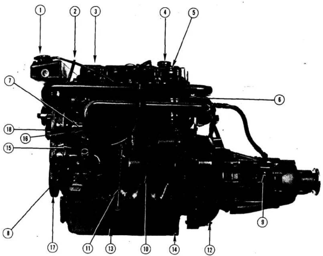
Fig. 3(e)
KEY TO 4.236 (M) ENGINE PHOTOGRAPHS
- Coolant Filler Cap
- Front Lifting Eye
- Rocker Cover
- Lubricating Oil Filler Cap
- Injector
- Fuel Oil Filter
- Fuel Injection Pump
- Sea Water Inlet to Sea Water Pump
- Gearbox Filler Plug and Dip-Stick
- Starter Motor
- Engine Oil Dipstick
-
Flywheel Housing
-
Lubricating Oil Pan
- Lubricating Oil Pan Drain Plug
- Sea Water Pump
- Water Pipe from Sea Water Pump to Cooler
- Crankshaft Pulley
- Timing Case Cover
- Alternator Pulley
- Heat Exchanger
20a. Zinc Anode - Engine Oil Cooler
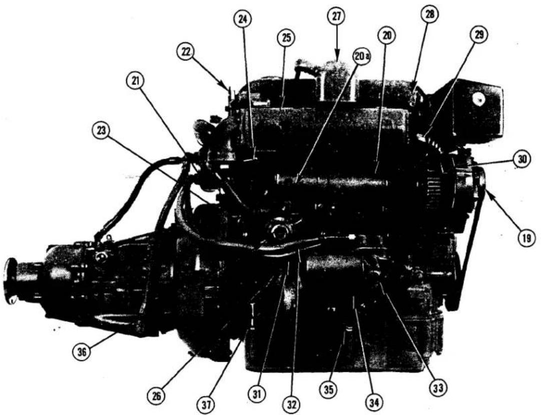
Fig. 3(f)
- Rear Lifting Eye
- Cylinder Block Drain Tap
- Exhaust Manifold Drain Tap
- Exhaust Manifold
- Cylinder Block
- Air Filter
- Induction Manifold
- Water Pipe from Heat Exchanger to Exhaust Manifold
- Alternator
- Oil Pipe to Cooler
- Oil Pipe from Cooler
-
Oil Filter Adaptor
-
Lubricating Oil Filter
- Optional Dipstick Position
- Fuel Transfer Pump
- Oil Pan Draining Connection
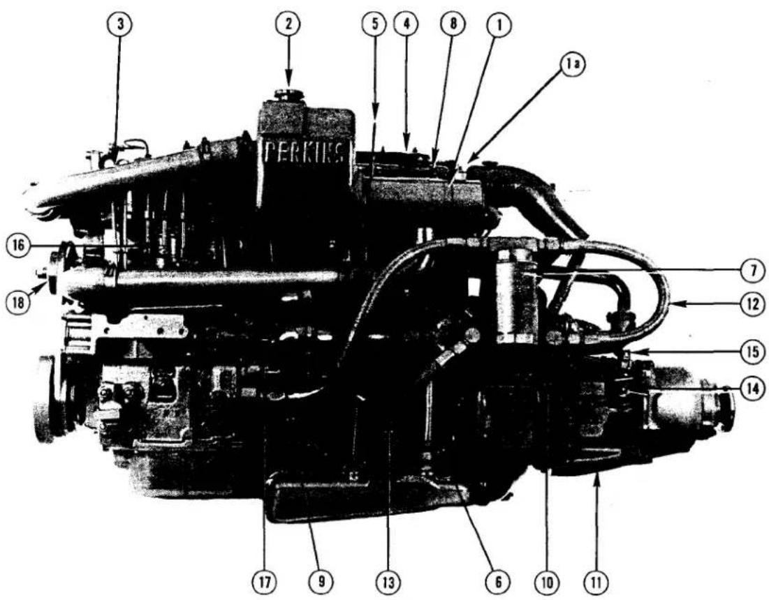
Fig. 3(g)
KEY TO 6.354 (M) ENGINE PHOTOGRAPHS
- Heat Exchanger
1a. Zinc Anode - Fresh Water Filler Cap
- Fuel Filter
- Lubricating Oil Filler Cap
- Lub Oil Dipstick
- Engine Breather Pipe
- Lubricating Oil Filter
- Injector
- Lubricating Oil Hose, Filter to Adaptor
- Engine Oil Cooler
- Gearbox
- Lubricating Oil Hose, Filter to Cooler
- Lubricating Oil Hose, Cooler to Adaptor
- Gearbox Filler/Dipstick
- Forward/Reverse Lever
- Injection Pump
- Sea Water Pump
- Fresh Water Pump
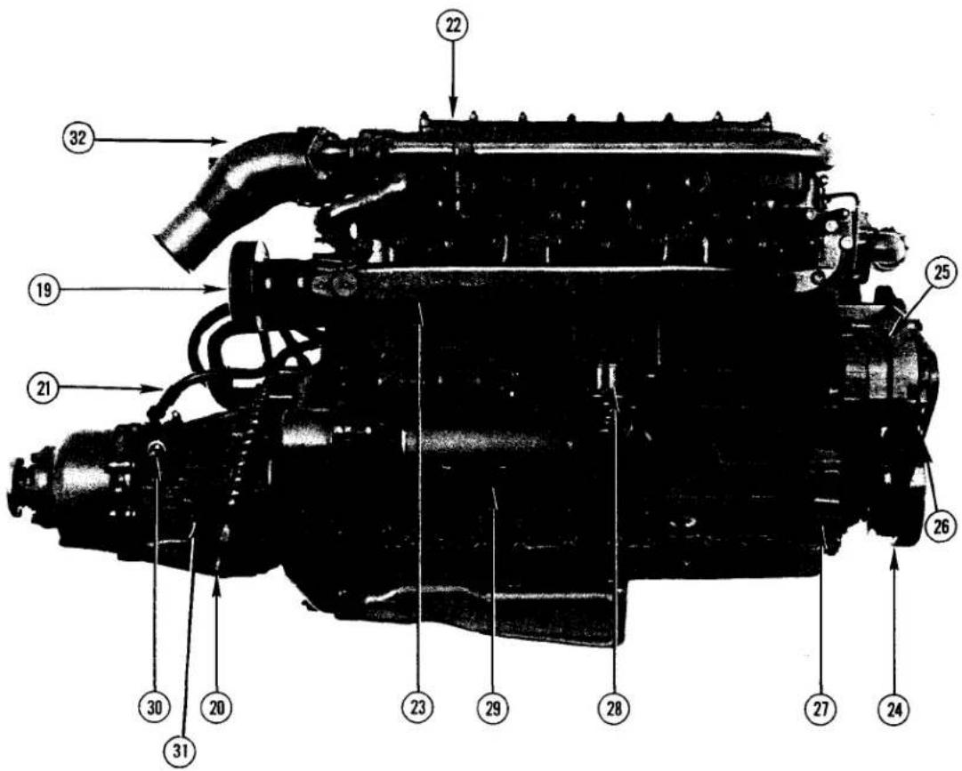
Fig. 3(h)
- Air Filter
- Gearbox Fluid Hose from Cooler
- Gearbox Fluid Hose to Cooler
- Water Cooled Exhaust Manifold
- Intake Manifold
- Crankshaft Pulley
- Alternator
- Alternator and Fresh Water Pump Drive Belt
- Engine Front Support Bracket
- Fuel Oil Transfer Pump (with Priming Lever)
- Starter Motor
- Gearbox Neutral Switch
- Rear Mounting Position
- Wet Elbow Exhaust
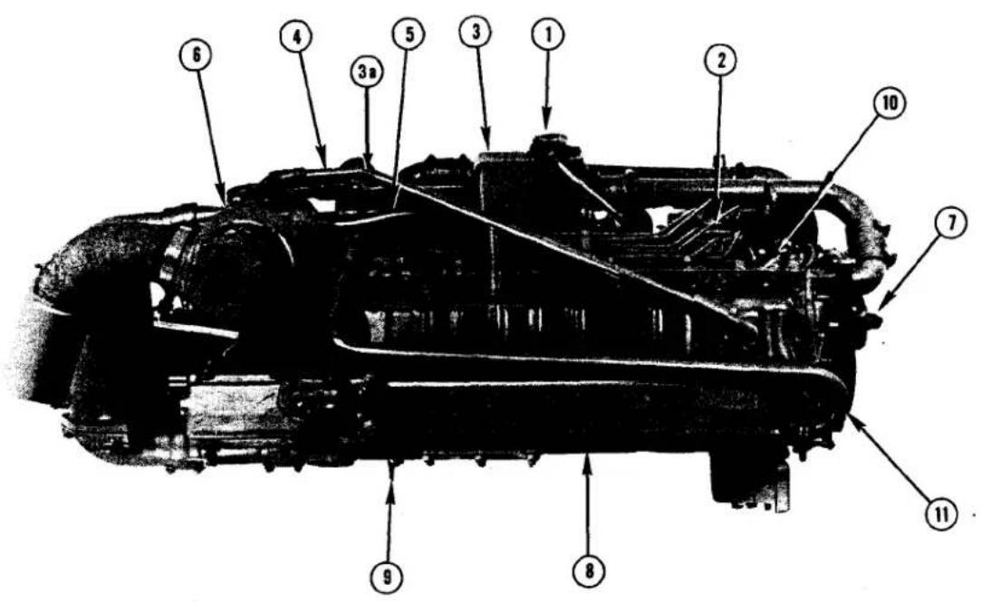
Fig. 3(i)
KEY TO HT6.354 (M) ENGINE PHOTOGRAPHS
- Fresh Water Filler Cap
- Fuel Injection Pump
- Header Tank
3a. Zinc Anode - Engine Breather Pipe
- Lubricating Oil Pressure Feed Hose to Turbocharger
- Turbocharger
- Fresh Water Pump
- Exhaust Manifold
- Water Drain Tap
- Injector
- Heat Exchanger to Exhaust Manifold Pipe
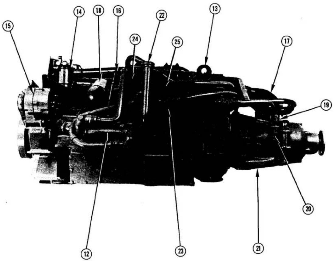
Fig. 3(j)
- Oil Cooler
- Lifting Bracket
- Fuel Filter
- Alternator
- Dipstick
- Air Charge Cooler
- Lub Oil Filter
- Gearbox Forward/Reverse Lever
- Gearbox Filler/Dipstick
- Gearbox
- Lub Oil Filler Cap
- Lub Oil/Gearbox Fluid Cooler
- Sea Water Pump
- Starter Motor
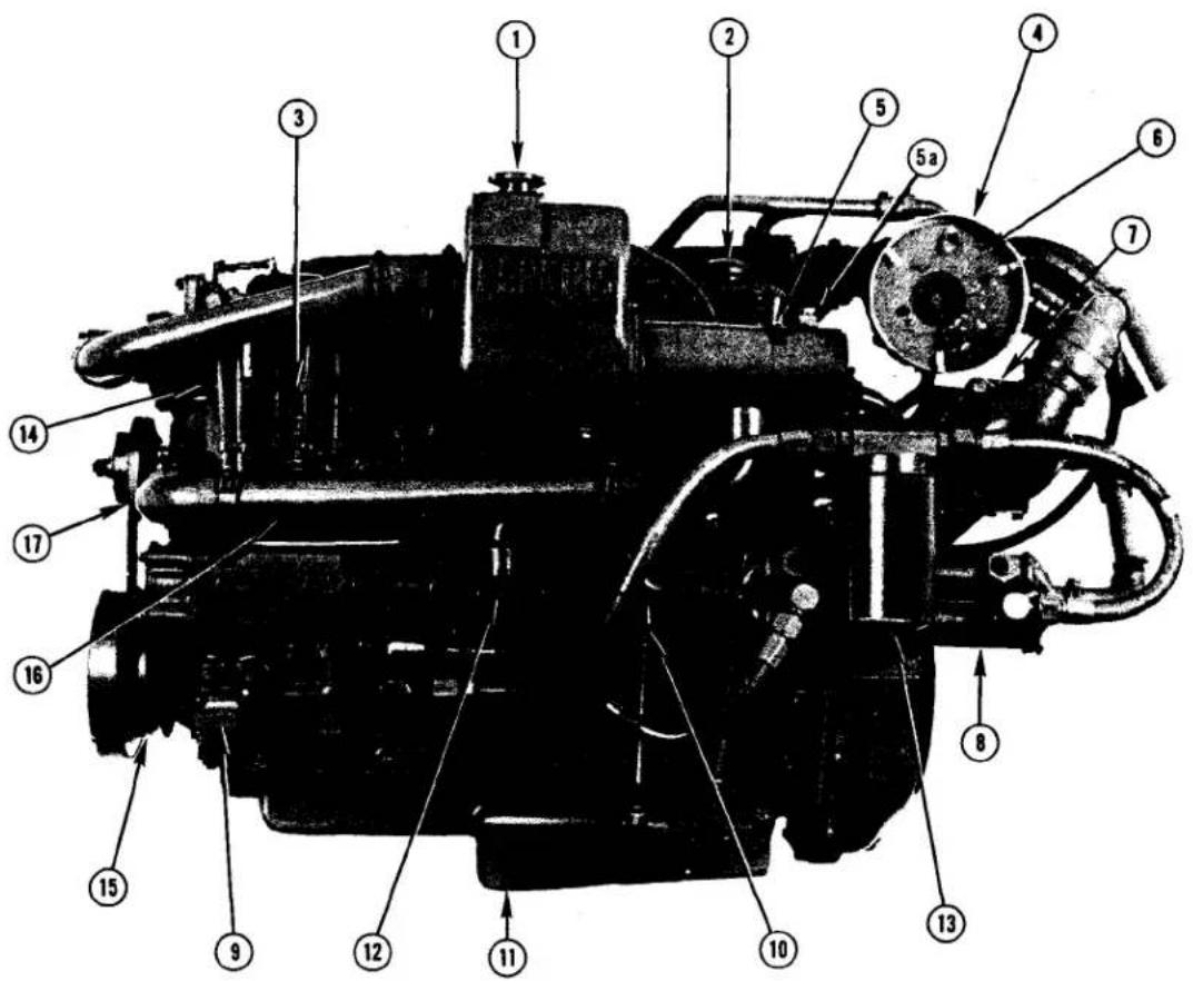
Fig. 3(k)
KEY TO T6.354 (M) ENGINE PHOTOGRAPH
- Fresh Water Filler Cap
- Lubricating Oil Filler Cap
- Fuel Injection Pump
- Turbocharger Air Intake
- Heat Exchanger
5a. Zinc Anode - Air Cleaner
- Air Charge Cooler
-
Oil Coolers
-
Front Engine Support Bracket
- Lubricating Oil Pan Dipstick
- Lubricating Oil Pan
- Sea Water Pump (L.H. Rotating Engine)
- Lubricating Oil Filter
- Fuel Filter
- Crankshaft Pulley
- Fresh Water Pipe (Heat Exchanger to Pump)
- Fresh Water Pump Pulley
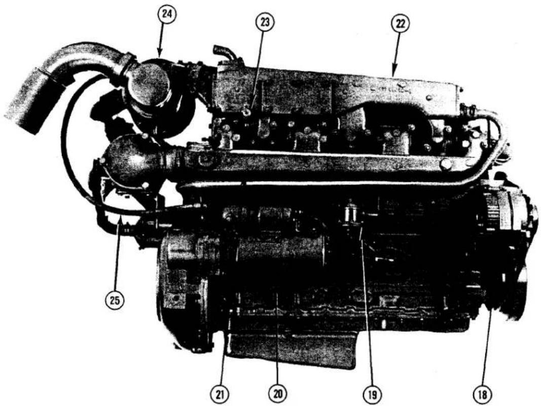
Fig. 3(I)
- Alternator
- Fuel Transfer Pump (with Priming Lever)
- Starter Motor
- Intake Manifold
- Exhaust Manifold
- Water Drain Tap
- Turbocharger
- Oil Line To Turbocharger
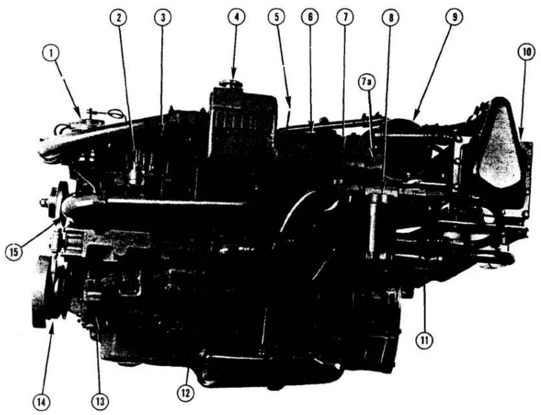
Fig. 3 (m)
KEY TO T6.354 MGT ENGINE PHOTOGRAPHS
- Fuel Filter
- Injection Pump
- Injector
- Fresh Water Filler Cap
- Lub Oil Dipstick
- Lub Oil Filler Cap
- Heat Exchanger
7a. Zinc Anode - Lub Oil Filter
- Air Filter
- Intercooler
11 Oil Coolers - Sea Water Pump
- Front Engine Mount
- Crankshaft Pulley
- Fresh Water Pump
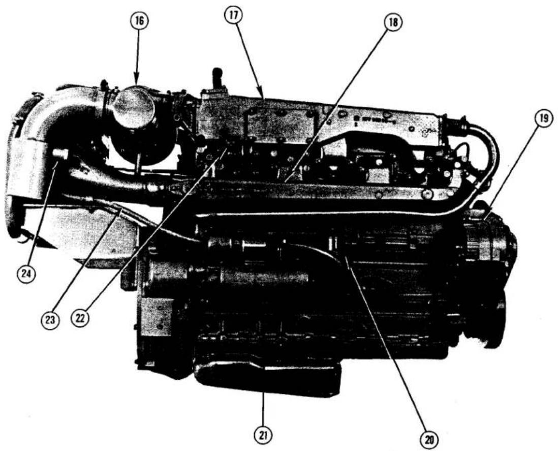
Fig. 3(n)
- Turbocharger
- Exhaust Manifold
- Intake Manifold
- Alternator
- Fuel Lift Pump (with Priming Lever)
- Starter Motor
- Drain Tap
- Oil Line to Turbocharger
- Sea Water Inlet from Exhaust Manifold
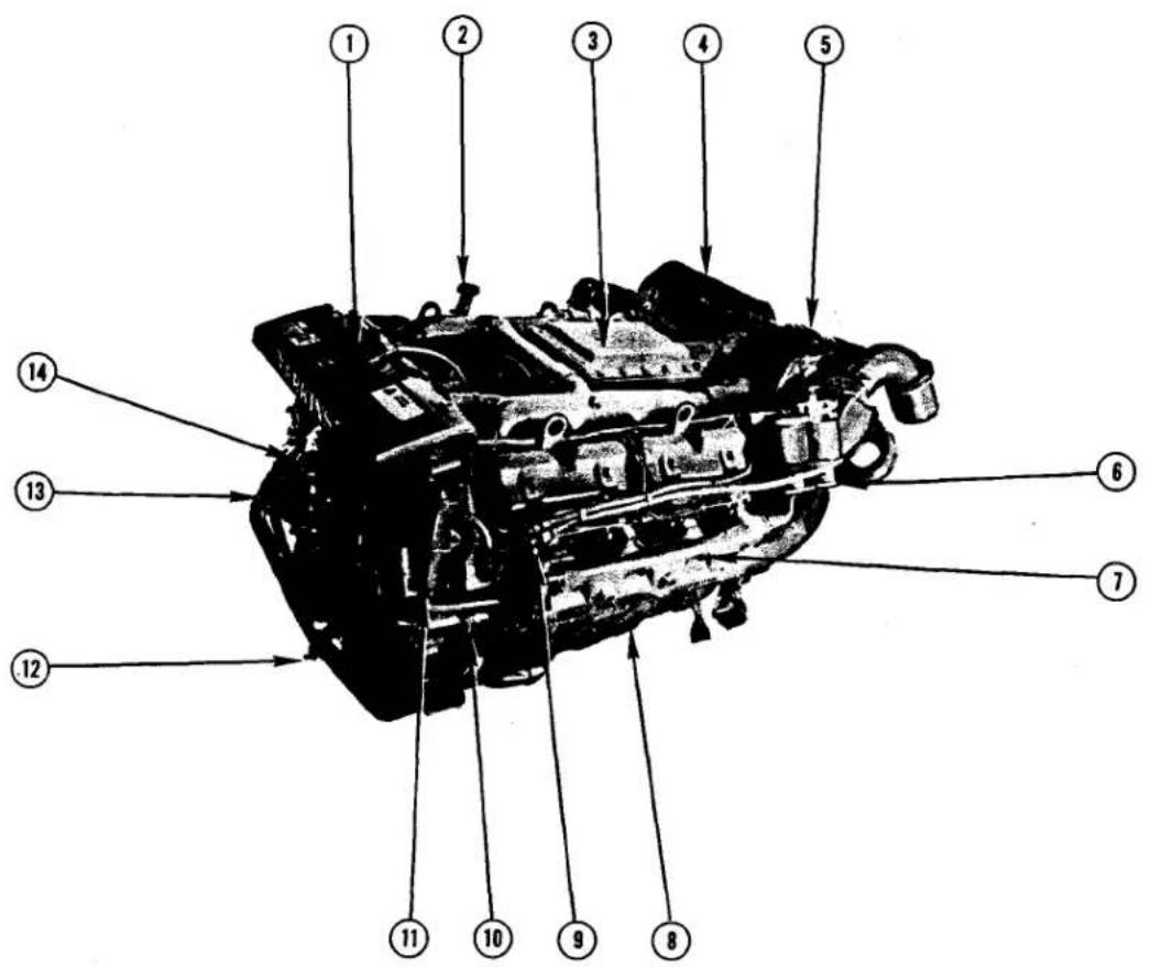
Fig. 3(o)
KEY TO TV8.510 (M) ENGINE PHOTOGRAPH
- Fresh Water Filler Cap
- Lub Oil Filler Cap
- Intercooler
- Air Filter
- Turbocharger
- Twin Element Fuel Filter
- Exhaust Manifold
- Starter Motor
- Injector
- Sea Water Pump
- Oil Pan Drain Pump
- Drain Tap
- Alternator
- Fresh Water Pump
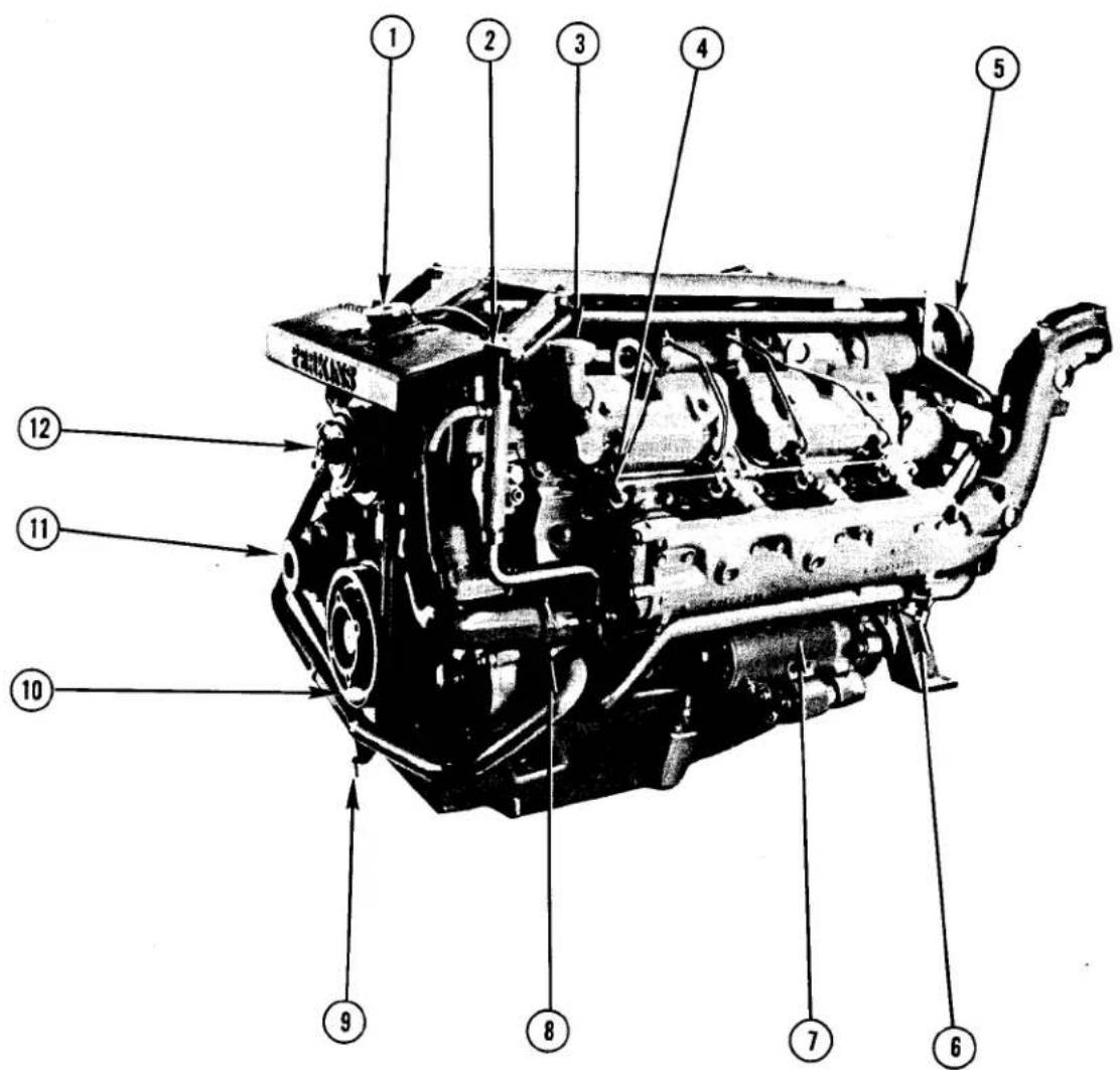
Fig. 3(p)
KEY TO V8.510 (M) ENGINE PHOTOGRAPH
- Fresh Water Filler Cap
- Oil Pan Drain Pump
- Lub Oil Filler Cap
- Injector
- Air Intake Filter
- Water Drain Tap
- Starter Motor
- Sea Water Pump
- Water Drain Tap
- Crankshaft Pulley
- Alternator
- Fresh Water Pump
ENGINE SPECIFICATIONS
4.108 (M)
Engine Type:
Maximum Shaft Horsepower:
Displacement:
Bore and Stroke:
Compression Ratio:
Firing Order:
Lub Oil Capacity:
Coolant Capacity:
*Special Rating
In-Line 4-Cylinder, 4-Cycle, Indirect Injection
47 @ 4000* rpm (35.1 skw), 45 @ 3600
rpm (32.8 skw)
107.4 cu. in. (1.76 Litres)
3.125 × 3.5 in. (79.4 mm × 88.9 mm)
22:1
1,3,4,2
4.2 U.S. Quarts (3.97 Litres)
In-Line 4-Cylinder, 4 cycle, Indirect Injection
58 @ 3000 rpm (43.3 skw)
153.9 cu. in. (2.53 Litres)
3.5 x 4.0 in. (88.9 mm x 101.6 mm)
21.5:1
1, 3, 4, 2
9.9 U.S. Quarts (9.37 Litres)
In-Line 4-Cylinder, 4-cycle, Direct Injection
72 @ 2500 rpm (53.7 skw)
235.9 cu. in. (3.88 Litres)
3.875 x 5.0 in. (98.43 mm x 127 mm)
16:1
1, 3, 4, 2
8.4 U.S. Quarts (7.95 Litres)
3.5 U.S. Gallons (13.25 Litres)
6.354 (M)
Engine Type:
Maximum Shaft Horsepower:
Displacement:
Bore and Stroke:
Compression Ratio:
Firing Order:
(Standard Rotation)
Firing Order:
(Contra-Rotation)
Lub Oil Capacity:
Coolant Capacity:
In-Line 6-Cylinder, 4-cycle, Direct Injection
115 @ 2800 rpm (85.8 skw)
354.0 cu. in. (5.8 Litres)
3.875 × 5.0 in. (98.4 mm × 127 mm)
16.1
1, 5, 3, 6, 2, 4
1, 4, 2, 6, 3, 5
10.8 U.S. Quarts (10.22 Litres)
5.4 U.S. Gallons (20.44 Litres)
| T6.354 (M) & HT6.354 (M) | |
| Engine Type: | Turbocharged In-Line 6-Cylinder4-Cycle, Direct Injection |
| Maximum Shaft Horsepower: | 145 @ 2400 rpm (108.2 skw) |
| Displacement: | 354.0 cu. in. (5.8 Litres) |
| Bore and Stroke: | 3.875 x 5.0 in. (98.4 mm x 127 mm) |
| Compression Ratio: | 15.5:1 |
| Firing Order(Standard Rotation) | 1, 5, 3, 6, 2, 4 |
| Firing Order:(Contra-Rotation) | 1, 4, 2, 6, 3, 5 |
| Lub Oil Capacity T6.354M | 12.6 U.S. Quarts (11.92 Litres) |
| Lub Oil Capacity HT6.354M | 13.8 U.S.Quarts (13.05 Litres) |
| Coolant Capacity: | 5.4 U.S. Gallons (20.44 Litres) |
| T6.354 MGT | |
| Engine Type: | Turbocharged In-Line 6-Cylinder,4-Cycle, Direct Injection |
| Maximum Shaft Horsepower: | 175 @ 2400 rpm (130.6 skw) |
| Displacement: | 354.0 cu. in. (5.8 Litres) |
| Bore and Stroke: | 3.875 x 5.0 in. (98.4 mm x 127 mm) |
| Compression Ratio: | 15.5:1 |
| Firing Order:(Standard Rotation) | 1, 5, 3, 6, 2, 4 |
| Firing Order:(Contra-Rotation) | 1, 4, 2, 6, 3, 5 |
| Lub Oil Capacity: | 10.8 U.S. Quarts (10.22 Litres) |
| Coolant Capacity: | 5.4 U.S. Gallons (20.44 Litres) |
| V8.510 (M) | |
| Engine Type: | 90° V8-Cylinder, 4-Cycle, Direct In |
| Maximum Shaft Horsepower: | 172 @ 2800 rpm (128.3 skw) |
| Displacement: | 510.7 cu. in. (8.36 Litres) |
| Bore and Stroke: | 4.25 x 4.50 in. (108 mm x 114.3 mm |
| Compression Ratio: | 16.5:1 |
| Firing Order: | 1, 8, 7, 5, 4, 3, 6, 2 |
| Lub Oil Capacity: | 18.6 U.S. Quarts (17.6 Litres) |
| Coolant Capacity: | 9.3 U.S. Gallons (35.2 Litres) |
| TV8.510 (M) | |
| Engine Type: | Turbocharged 90° V8-Cylinder, 4-CDirect Injection |
| Maximum Shaft Horsepower: | 235 @ 2600 rpm (175.3 skw) |
| Displacement: | 510.7 cu. in. (8.36 Litres) |
| Bore and Stroke: | 4.25 x 4.50 in. (108 mm x 114.3 mm |
| Compression Ratio: | 15:1 |
| Firing Order: | 1, 8, 7, 5, 4, 3, 6, 2 |
| Lub Oil Capacity: | 18.6 U.S. Quarts (17.6 Litres) |
| Coolant Capacity: | 9.3 U.S. Gallons (35.2 Litres) |
INSTRUMENTS
Engine monitoring instruments provide the operator with important information concerning the operating condition of the engine. Generally, the instruments are not as precise as test instruments but they will provide sufficiently accurate indications of the operating condition of the engine.
ENGINE OIL PRESSURE GAUGE
This is one of the most important instruments and should be checked as soon as the engine starts. Normal oil pressure is 30/60 P.S.I. (2.1/4.2 kgf/cm 2) at maximum engine speed with the engine at normal operating temperature. During the life of the engine, as bearing surfaces wear, there will be a gradual decrease in pressure, There will also be a slight decrease in pressure when the oil is hot or if the wrong grade of oil is used during certain climatic conditions. Refer to page 58 for the correct oil grades.
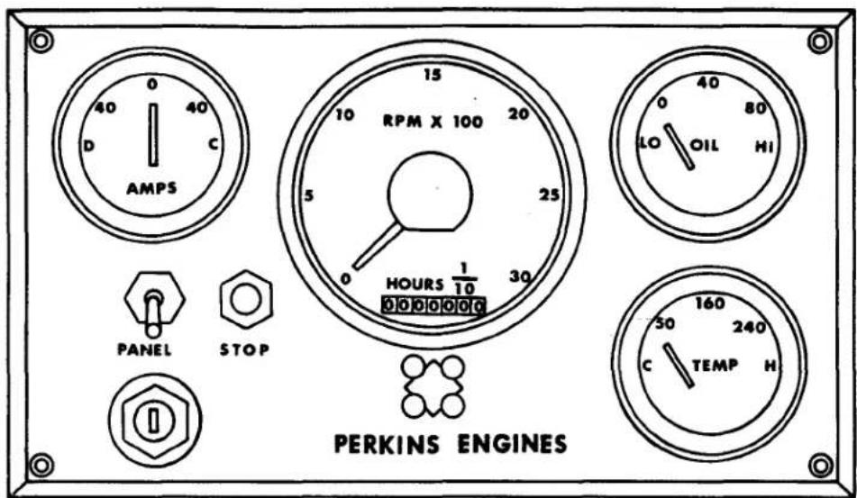
Fig. 4 Typical Instrument Panel
TACHOMETER
This instrument provides the operator with the speed, in revolutions per minute (rpm), of the engine crankshaft. The value indicated on the dial usually has to be multiplied by one hundred (100) to arrive at the engine rpm. (e.g., 20 x 100 = 2,000 rpm). NOTE: Initial calibration may be required for certain tachometers.
WATER TEMPERATURE GAUGE
This instrument provides the operator with the temperature of the engine coolant. The coolant temperature (normal) should remain within the ranges listed on page 54. If a higher than normal temperature is experienced, investigate and correct immediately (refer to page 54).
AMMETER
This instrument provides the operator with an indication of whether or not the battery is being charged by the alternator. An indication that the battery is discharging should be investigated and corrected immediately.
STARTING AND STOPPING ENGINE
PREPARATION FOR STARTING
ENSURE FUEL IS TURNED ON!
Open engine coolant seacocks (does not apply to keel cooled engines).
Check coolant level in header tank.
Check engine and gearbox lubricating oil levels (see pages 56 and 59 for oil specifications). When checking oil level on HT6.354 engines, the procedure outlined on page 56 should be followed. If a V8.510 engine (with in-line pump) has not been running for a period exceeding one month, a pint of engine lub oil should be added to the fuel injection pump through the filler plug. (See 1, Fig. 12 (b), page 50).
Ensure that the fuel tank contains considerably more than the amount of fuel necessary for the intended voyage. The fuel oil should conform to one of the specifications listed on page 45.

External assemblies and accessories driven by an engine, such as pulleys, belts, and alternator/generator, are hazardous to anyone attempting to repair or service it while it is operating. If possible, always stop your engine before servicing it. When necessary to repair or adjust an operating engine, use extreme caution and do not wear loose clothing.
STARTING THE ENGINE
Engine controls and instruments will vary according to each individual boat builders preference but, in general, the following instructions are applicable to all Perkins marine engines installed in boats manufactured in North America.
- Place the gearbox in neutral position (Borg-Warner gearboxes have a neutral safety switch that prevents starting in any other position).
If the engine has not been started for five or more days, it may be necessary to either turn the engine over several times with the starter or operate the priming lever several times to build up the fuel pressure. - Place the engine speed control at the maximum *speed position.
- Press start button or turn the key in clockwise direction - release as soon as the engine starts. If the engine fails to run, ensure that the starter pinion and engine have stopped rotating before re-engaging the starter motor. Otherwise, the flywheel ring and starter pinion could be damaged.
- Place the engine speed control at the position of desired engine rpm.
*For TV8.510 (M) engines, place the engine speed control at one-quarter ( 14 ) of maximum speed if the engine or weather is warm or at the maximum speed position, if cold.
COLD WEATHER STARTING
The exact temperature where use of a "Thermostat" is necessary varies from engine to engine and also according to many other variables. In general, if the temperature is below 40^ F ( 3^ - 4^ C) and, upon attempting to start an engine, it turns over rapidly, exhausts white smoke but does not start, the use of a "Thermostat" is necessary.
TO USE A THERMOSTART -
- If the fuel line has a valve, ensure that it is turned to the "on" position.
- Move the speed control to the maximum position.
- Push and hold the button labeled "Heater" for 15 to 20 seconds. (Note: Some installations employ key start switches with a "Heater" position).
- Engage the starter motor. If the engine does not start in 20 seconds, release the button. After 10 seconds re-engage the starter motor. If the engine will not start, check to ensure there is fuel at the inlet and 12V at the electrical terminal on the "Thermostat". If both are present, remove the air filter housing (or air duct) and visually observe the device to determine if it glows red when the heater switch is engaged. If not, the device is faulty and must be replaced. If there is no fuel at the inlet, ensure that all valves between the fuel supply source and the "Thermostat" are open. If this is not the cause, the next step is to "bleed" the low pressure fuel system. Refer to "bleeding", page 46. If 12V are not available, troubleshoot electrical system.
- As soon as the engine starts, release starter switch, adjust the throttle for the lowest smooth running engine rpm and allow the engine to warm up.
- If applicable, close the "Thermostat" fuel supply valve.
When the engine starts, check:
-
Oil pressure guage for sufficient oil pressure.
-
Alternator ammeter for an indication that the battery is being re-charged.
-
Sea water coolant discharge for evidence of proper circulation (not applicable to keel cooled engines).
OPERATING PRECAUTIONS
A new Perkins engine can be operated at full load when first used, provided sufficient time is allowed for the engine to attain a temperature of at least 140°F (60°C) before full load is applied. Gradual engine "break-in" is not necessary. In fact, prolonged engine operation with a light load can be harmful because, under these conditions, the piston rings may not seat properly within the cylinder liners.
Engine oil pressure and level should be very closely monitored until it has been established that the engine is functioning normally.
Do not operate the engine at maximum speed for long periods of time. The table on page 33 lists the maximum intermittent and continuous speeds for each respective engine type. An engine should not be operated at maximum speed for a period in excess of one hour. After operating at maximum speed, reduce the speed to maximum continuous rpm* for at least 15 minutes before returning to maximum speed. If an engine is "loaded down" and runs at less than the maximum speed when at full throttle, the same precaution applies.
*The speed of pleasure craft TV8.510 (M) engines must be reduced 200 rpm for a period of two hours before being returned to maximum.
| ENGINE TYPE | MAXIMUM INTERMITTENT SPEED (RPM) | MAXIMUM CONTINUOUS SPEED (RPM) |
| 4.108 (M) | 3,600 | 3,000 |
| 4,000(Special Rating) | ||
| 4.154 (M) | 3,000 | 3,000 |
| 4.236 (M) | 2,500 | 2,250 |
| 6.354 (M) | 2,800 | 2,400 |
| T6.354 (M) | 2,400 | 2,250 |
| HT6.354 (M) | ||
| T6.354 MGT | 2,400 | 2,250 |
| V8.510 (M) | 2,800 | 2,500(Medium Duty Rating)2,000(Heavy Duty Rating) |
| TV8.510 (M) | 2,600(Pleasure Craft,planing and lightdisplacement) | 2,400 |
| 2,400(Light Commercialcraft) | 2,200 |
STOPPING THE ENGINE
A spring loaded "stop control" push button switch (electric) is located on or near the instrument panel. This switch, in conjunction with a solenoid on the injection pump, functions to stop the flow of fuel to the injection pump.
To stop the engine, press the button until the engine stops running, release, turn the key to the "off" position and place the engine speed control in the minimum speed position.
Some boats may have a mechanical spring loaded pull-to-stop control instead of an electric push button. To stop an engine having this type of control, pull the knob and hold until engine rotation ceases. Upon releasing the knob, ensure it returns to its normal position (i.e., the "run" position) so that the engine may be re-started without difficulty.
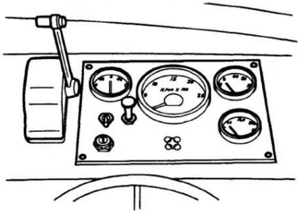
Fig. 5 Typical Engine Control Console
SCHEDULED MAINTENANCE
A Perkins marine engine will have a long and trouble free life provided it is maintained in accordance with the following schedule:
4.108 (M) Engines
DAILY
Check coolant in header tank (see warning on Page 54).
Check engine lub oil level (see page 56).
Check engine oil pressure (if equipped with gauge).
Check gearbox fluid level (see page 59).
FIRST 25/50 HOURS
Change engine lub oil (see page 58).
Renew engine lub oil filter element (s) (see page 57).
Check cylinder head nuts/setscrews for correct torque (see page 41).
Set valve clearances to 0.012 in. (0.30 mm) cold (see page 61).
Check coolant level (header tank) and inspect for coolant leaks.
Check external nuts, setscrews, mounting, etc. for tightness.
Check drive belt tension (see page 56)
Check electrical equipment and connections.
Check for lub and fuel oil leaks.
Check engine idling speed (see page 50).
Check general performance of engine.
EVERY 100 HOURS OR 2 MONTHS (WHICHEVER OCCURS FIRST)
Change engine lub oil (see page 58).
Renew engine lub oil filter element (s) (see page 57).
Clean air intake filter.
*Check drive belt tension (see page 56).
Clean water trap (if equipped).
Check engine for leakage of oil and water.
Change gearbox fluid (Paragon) (see page 61).
EVERY 400 HOURS OR 12 MONTHS (WHICHEVER OCCURS FIRST)
Renew final fuel filter element (see page 49).
Check hoses and clamps.
Drain and clean fuel tank.
Change gearbox fluid (Borg-Warner) (see page 59).
EVERY 800 HOURS
Check sea water pump impeller (see page 54).
EVERY 2,400 HOURS
Arrange for examination and service of accessory equipment, (i.e., starter motor, alternator, etc.).
Service injectors (see page 53).
Check and adjust valve tip clearances (see page 61).
*Drive belt tension should be checked monthly on engines rated above 3000 rpm.
4.154 (M) Engines
DAILY
Check coolant level in header tank(see warning on page 54).
Check engine lub oil level (see page 56).
Check engine oil pressure (if equipped with gauge).
Check gearbox fluid level (see page 59).
FIRST 25/50 HOURS
Change engine lub oil (see page 58).
Renew engine lub oil filter element (s) (see page 57).
Check cylinder head nuts/setscrews for correct torque (see page 41).
Set valve clearances to 0.012 in (0.30mm) cold (see page 61).
Check coolant level (header tank) and inspect for coolant leaks.
Check external nuts, setscrews, mountings, etc. for tightness.
Check drive belt tension (see page 56).
Check electrical equipment and connections.
Check for lub and fuel oil leaks.
Check engine idling speed (see page 50).
Check general performance of engine.
EVERY 100 HOURS OR 2 MONTHS (WHICHEVER OCCURS FIRST)
Clean air intake filter.
EVERY 200 HOURS OR 4 MONTHS (WHICHEVER OCCURS FIRST)
Change engine lub oil (see page 58).
Renew engine lub oil filter element (s) (see page 57).
Check drive belt tension (see page 56).
Check engine for leakage of oil and water.
Clean water trap (if equipped).
EVERY 400 HOURS OR 12 MONTHS (WHICHEVER OCCURS FIRST)
Renew final fuel filter element.
Check hoses and clamps.
Drain and clean fuel tank.
Change gearbox fluid (see page 59).
EVERY 800 HOURS
Check sea water pump impeller (see page 54).
EVERY 2,400 HOURS
Arrange for examination and service of accessory equipment (i.e., starter motor, alternator, etc.).
Check and adjust valve tip clearances (see page 61).
Service injectors (see page 53).
4.236 (M) Engines
DAILY
Check coolant level in header tank (see warning on page 54).
Check engine lub oil level (see page 56).
Check engine oil pressure (if equipped with gauge).
Check gearbox fluid level (see page 59).
FIRST 25/50 HOURS
Change engine lub oil (see page 58).
Renew engine lub oil filter element (s) (see page 57).
Check cylinder head nuts/setscrews for correct torque (see page 41).
Set valve clearances to 0.012 in. (0.30 mm) cold (see page 61).
Check coolant level (header tank) and inspect for coolant leaks.
Check external nuts, setscrews, mounting, etc. for tightness.
Check drive belt tension (see page 56).
Check electrical equipment and connections.
Check for lub and fuel oil leaks.
Check engine idling speed (see page 50).
Check general performance of engine.
EVERY 100 HOURS OR 2 MONTHS (WHICHEVER OCCURS FIRST)
Clean air intake filter.
EVERY 200 HOURS OR 4 MONTHS (WHICHEVER OCCURS FIRST)
Change engine lub oil (see page 58).
Renew engine lub oil filter element (s) (see page 57).
Check drive belt tension (see page 56).
Check engine for leakage of oil and water.
Clean water trap (if equipped).
EVERY 400 HOURS OR 12 MONTHS (WHICHEVER OCCURS FIRST)
Renew final fuel filter element (see page 49).
Check hoses and clamps.
Clean fuel lift pump strainer.
Drain and clean fuel tank.
Change gearbox fluid (see page 59).
EVERY 800 HOURS
Check sea water pump impeller (see page 54).
EVERY 2,400 HOURS
Arrange for examination and service of accessory equipment
(i.e., starter motor, alternator, etc.)
Service injectors (see page 53).
Check and adjust valve tip clearances (see page 61).
6.354 (M), T6.354 (M), T6.354 MGT & HT6.354 (M) Engines
DAILY
Check coolant level (see warning on page 54).
Check engine lub oil level (see page 56).
Check engine oil pressure (if equipped with gauge).
Check gearbox fluid level (see page 59).
FIRST 25/50 HOURS
Change engine lub oil (see page 58).
Renew engine lub oil filter element (s) (see page 57).
Check cylinder head nuts/setscrews for correct torque (see page 40).
Set valve clearances to 0.012 in. (0.30 mm) cold (see page 61).
Check coolant level (header tank) and inspect for coolant leaks.
Check external nuts, setscrews, mountings, etc. for tightness.
Check drive belt tension (see page 56).
Check electrical equipment and connections.
Check for lub and fuel oil leaks.
Check engine idling speed (see page 50).
Check general performance of engine.
EVERY 100 HOURS OR 2 MONTHS WHICHEVER OCCURS FIRST)
Clean air intake filter.
Change engine lub oil - Turbocharged engines with API "CC" oil only. (see page 58).
Service Injectors (T6.354 MGT only).
EVERY 200 HOURS OR 4 MONTHS (WHICHEVER OCCURS FIRST)
Change engine lub oil (see page 58).
Renew engine lub oil filter element (s) (see page 57).
Check drive belt tension (see page 56).
Clean water trap (if equipped).
Check engine for leakage of oil and water.
EVERY 400 HOURS OR 12 MONTHS (WHICHEVER OCCURS FIRST)
Clean fuel lift pump strainer.
Renew final fuel filter element (see page 49).
Check hoses and clamps.
Drain and clean fuel tank.
Change gearbox fluid (Borg-Warner), (see page 59).
EVERY 800 HOURS
Clean turbocharger impeller, diffuser and oil drain pipe.
Change gearbox lub oil (Twin Disc MG-502 and MG-506), (see page 59).
Check sea water pump impeller (see page 54).
(NOTE: For engines equipped with air charge (intercoolers) coolers refer to page 55).
EVERY 2,400 HOURS
Arrange for examination and service of accessory equipment(i.e., starter motor, alternator, etc.).
Service Injectors (see page 53).
Check and adjust valve tip clearances (see page 61).
V8.510 (M) Engines
DAILY
Check coolant level (see warning on page 54).
Check engine lub oil level (see page 56).
Check oil pressure (if equipped with gauge).
Check gearbox fluid or lub oil level (see pages 59 and 61).
FIRST 25/50 HOURS
Change engine lub oil (see page 58).
Renew engine lub oil filter element (s) (see page 57).
Set valve clearances to 0.012 in. (0.30 mm) cold (see page 61).
Check coolant level (header tank) and inspect for coolant leaks.
Check external nuts, setscrews, mountings, etc. for tightness.
Check drive belt tension (see page 56).
Check electrical equipment and connections.
Check for lub and fuel oil leaks.
Check engine idling speed (see page 50).
Check general performance of engine.
EVERY 100 HOURS OR 2 MONTHS (WHICHEVER OCCURS FIRST)
Clean air intake filter.
EVERY 200 HOURS OR 4 MONTHS (WHICHEVER OCCURS FIRST)
Change engine lub oil (see page 58).
Renew engine lub oil filter elements (see page 57).
Check drive belt tension (see page 56).
Clean water trap (if equipped)
Check engine for leakage of oil and water.
EVERY 400 HOURS OR 12 MONTHS (WHICHEVER OCCURS FIRST)
Renew final fuel filter elements (see page 49).
Service injectors (see page 53).
Check and adjust valve tip clearances (see page 61).
Check hoses and clamps.
Drain and clean fuel tanks.
Change gearbox fluid (Borg-Warner), (see page 59).
Clean fuel lift pump strainer.
EVERY 800 HOURS
Check sea water pump impeller (see page 54).
Change gearbox lub oil (Twin Disc MG-506 and MG-502), (see page 59).
EVERY 2,400 HOURS
Arrange for examination and service of accessory equipment (i.e., starter motor, alternator, etc.).
TV8.510 (M) Engines
DAILY
Check coolant level (see warning on page 54).
Check engine lub oil level (see page 56).
Check gearbox fluid or lub oil level (see pages 59 and 61).
Check oil pressure (if equipped with gauge).
FIRST 25/50 HOURS
Change engine lub oil (see page 58).
Renew engine lub oil filter elements (see page 57).
Set valve clearances to 0.012 in (0.30 mm) cold (see page 61).
Check coolant level (header tank) and inspect for coolant leaks.
Check external nuts, setscrews, mountings, etc., for tightness.
Check drive belt tension (see page 56)
Check electrical equipment and connections.
Check for lub and fuel oil leaks.
Check engine idling speed (see page 50).
Check general performance of engine.
EVERY 100 HOURS OR 2 MONTHS (WHICHEVER OCCURS FIRST)
Clean air intake filter.
Change engine lub oil if using API "CC" oil (see page 58).
EVERY 200 HOURS OR 4 MONTHS (WHICHEVER OCCURS FIRST)
Change engine lub oil if using API "CD" oil (see page 58).
Renew engine lub oil filter elements (see page 57).
Check drive belt tension (see page 56).
Service injectors (see page 53).
Clean water trap (if equipped).
Check engine for leakage of oil and water.
EVERY 400 HOURS OR 12 MONTHS (WHICHEVER OCCURS FIRST)
Renew final fuel filter elements (see page 49).
Check and adjust valve tip clearances (see page 61).
Check hoses and clamps.
Drain and clean fuel tanks.
Change gearbox fluid (Borg-Warner), (see page 59).
Check gearbox oil/fluid cooler for water flow restrictions (see page 55).
Clean fuel lift pump strainer.
EVERY 800 HOURS
Clean turbocharger impeller, diffuser and oil drain pipe.
Check sea water pump impeller (see page 54).
Change gearbox lub oil (Twin Disc MG-502 and MG-506) (see page 59).
EVERY 2,400 HOURS
Arrange for examination and service of accessory equipment (i.e., starter motor, alternator, etc.). See page 62 for Air Charge Cooler servicing.
ALL ENGINES
The intervals listed are general in their application. The operator should compare the maintenance schedule for his particular engine with the schedule established by the manufacturer of his boat and should always adopt the shorter interval. Also, the maintenance intervals should be reduced to conform with any exceptional operating condition, such as continuous sustained high speeds or temperatures.
An operator usually is familiar with the water he is operating in, therefore, checking the weed trap (at the water intake) at appropriate intervals is left to his discretion.
The zinc pencil (anode) in the heat exchanger will need replacing periodically in accordance with the operating conditions of the boat and engine. Refer to the engine photographs for the respective location (not applicable to 4.154 (M) and V8.510/TV8.510 (M) engines).
The thermostat, in carrying out its function of controlling temperature can, contrary to general thoughts on the method of its operation, open and close numerous times during each hour of engine operation. In so doing, like any other type of mechanical device, it may not maintain its efficiency indefinitely. Therefore, it is recommended that it be replaced after each two years of operation or more frequently if there are indications that it is not functioning correctly.
CYLINDER HEAD TIGHTENING SEQUENCES
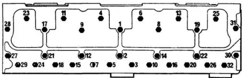
Fig. 6(a) Tightening Sequences for Cylinder Head Nuts and/or Setscrews 6.354 (M), T6,354 (M), HT6.354 (M). T6.354 MGT
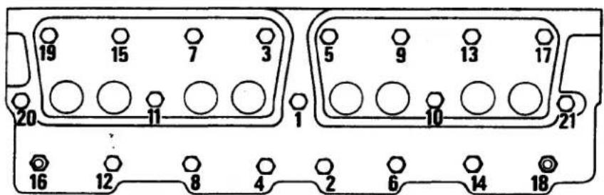
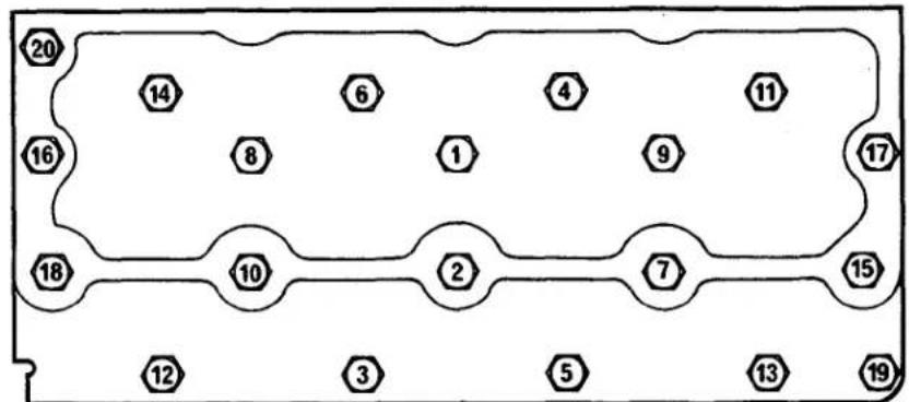
Fig. 6(b) Tightening Sequence for Cylinder Head Nuts and/or Setscrews V8.510/TV8.510 (M) (Applicable To Both Banks.)
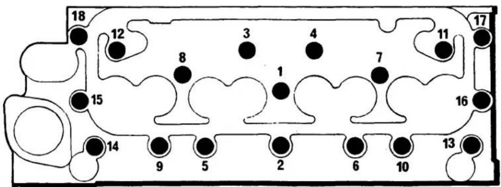
Fig. 6(c) 4.108 (M)
If a boat is to be stored for several months, the engine should be preserved as follows:
- Clean all external parts.
- Run engine until warm. Stop and drain the lub oil pan.
- Discard lub oil filter element (s), clean base (s), fill elements with new oil of an approved grade and install new element (s) (refer to page 57).
- Clean engine breather pipe (s).
- Fill lub oil pan to correct level with new oil of an approved grade (refer to page 58).
- Drain all fuel oil from fuel tanks and filters. Put at least one gallon of inhibiting oil into the fuel tank (refer to "Oil Recommended for Preservation of Fuel System", Page 44). If, because of the construction of the fuel tank, this quantity of oil is inadequate, disconnect the fuel feed line before the first filter and connect a small capacity auxiliary tank. If the tank (s) cannot be drained, they should be filled with fuel and a temporary tank (inserted in the fuel feed line) should be filled with an inhibiting oil.
- Bleed the fuel system as detailed on page 46.
- Start engine and run it at half speed for 15 minutes to circulate the oil through the injection pump, pipes and injectors.
- Seal the tank air vent (or filler cap) with waterproof adhesive tape.

natural_image
Black-and-white technical illustration of a mechanical assembly with no visible text or symbolsFig. 7 (a)
natural_image
Close-up of mechanical components including gears and springs, no visible text or symbolsFig. 7 (b)
- Drain water from heat exchanger and engine cylinder block. The heat exchanger should be removed and serviced. The cylinder block may be back-flushed through the drain points with the thermostat removed. If it is decided to refill the fresh water system partially with antifreeze, the precaution on page 45 should be noted. For 4.108 engines, "bleeding" may be necessary when filling the cooling system (refer to page 44, item 6)
- Remove the end plate from the sea water circulating pump and lubricate the interior of the pump body with Glycerine or MARFAK 2HD grease (refer to fig. 7) or remove impeller for the preservation period.
- Remove the injectors and spray into the cylinder bores 14 pint (0.014 litre) of lubricating oil divided between all cylinders. Rotate the crankshaft one complete revolution and replace injectors. Direct injection engines require an atomized spray.
- Remove the air cleaner (s) and any piping. Seal the air intake with waterproof adhesive tape.
- Remove the exhaust pipe (s) and seal the manifold port.
- Remove cylinder head cover (s), lubricate the rocker assembly and replace cover (s).
- Remove water pump drive belt (s).
- BATTERIES
a. Remove the battery (s) and fill cells with distilled water.
b. Recharge (see warning on page 63).
c. Clean the terminals and lightly smear with petroleum jelly.
d. Store in a cool, dry, dust free place. Avoid any freezing risk.
e. Recharge once a month.
- STARTERS AND ALTERNATORS
Clean terminals and smear lightly with petroleum jelly. The alternator, starter, and terminals must be protected from precipitation.
OIL RECOMMENDED FOR PRESERVATION OF FUEL SYSTEM
A fuel oil having the following characteristics should be used for preservation of the fuel system.
Viscosity: Should not be greater than 22 centistokes at the lowest ambient temperature expected upon restarting.
Pour Point: Must be at least 15^ (- 10^ C) lower than the lowest ambient temperature expected upon restarting and should be lower than the lowest temperature likely to be encountered during the storage period.
Example: Shell Fusus "A" or equivalent. In the event an oil of this type is not available, use clean, new #1 diesel fuel to prevent waxing at low temperatures.
PREPARING THE ENGINE FOR OPERATION
When the engine is to be returned to operating condition, the following procedure must be followed:
- Thoroughly clean all external parts and reinstall the sea water pump impeller (if removed).
- Remove tape from the fuel tank vent (or filler cap).
- Drain fuel tank to remove any remaining oil and condensed water and refill the tank with fuel oil. If tanks have been filled in lieu of draining, drain the water from the trap (if provided by the boat builder).
- Install new fuel filter element and vent the filter (see page 46).
- Vent and prime the fuel injection pump (see page 46).
- Close all coolant drain taps and fill the system with clean coolant. Check for leaks. If a 4.108 marine engine is installed with the front of the engine lower than the rear of the engine (this is not a recommended installation), it is possible for an air lock to develop when the cooling system is refilled. To prevent this, loosen the plugs on top of the manifold and cylinder head so that the air can escape during the refilling operation.
- Rotate fresh water coolant pump by hand to ensure freedom of the water pump seals. If the pump will not rotate with a reasonable amount of force, it will have to be removed to determine the cause of the restriction.
- Reinstall water pump drive belt (s).
- Remove the rocker cover (s), lubricate rocker assembly (s) with engine oil, and replace cover (s).
- Remove tape from the air intake (s), clean filter (s), reinstall the air cleaner (s), and any removed intake pipe.
- Remove tape from the exhaust manifold port and reinstall the exhaust pipe (s).
- STARTER AND ALTERNATOR Wipe the petroleum jelly from the terminals and check that all connections are secure.
- Connect the battery (s)
- Check the level and condition of the lub oil in the oil pan. Change the oil if necessary. Attend to the oil level in the in-line fuel injection pump (see page 48).
- Open raw water seacocks.
- Start the engine in the normal manner and check for sufficient oil pressure and battery charge. While the engine is reaching its normal operating temperature, check for water and oil leaks.
NOTE:
If the foregoing instructions are observed, the storage and return to operation should be efficient and without any adverse effect on the engine. However, Perkins Engines cannot accept liability for direct or consequential damage that might arise following periods of storage.
COLD WEATHER PRECAUTIONS
Precautions against damage from freezing should be taken if the engine is to be left exposed to cold weather. Either drain the cooling system or, where this is not convenient, a good quality anti-freeze that incorporates a suitable corrosion inhibitor may be used.
If anti-freeze is used to protect an engine from freeze damage, ascertain whether it is suitable for use in Perkins Engines and also ensure that it will have no harmful effect on the cooling system in general. Most popular brands (e.g., Prestone) are acceptable.

WARNING: HARMFUL OR FATAL IF SWALLOWED. If anti-freeze is swallowed, induce vomiting immediately. Call a physician. Do not store in open or unlabeled containers. KEEP OUT OF REACH OF CHILDREN.
To drain the cooling system, the taps on the cylinder block must be opened. There may be other drain taps on the exhaust manifold, oil cooler, etc., all of which must be opened.
When the engine is drained, the fresh water pump will also drain but, in sub-freezing weather, rotation of the pump may be prevented by:
a. locking of the impeller by ice because the pump hole was blocked by sediment and the pump was not completely drained.
b. locking of the seal because of frozen globules of moisture between the seal and the gland.
When operating in sub-freezing weather:
- Before starting the engine turn the fresh water pump by hand; this will indicate if the pump is frozen. If frozen, this should free any ice formation.
- If it is impossible to turn the pump by hand, the engine should be filled with warm water.
- To avoid this trouble, it is advisable, after the water has been drained, to run the engine for a few seconds at idling speed. This will disperse any moisture remaining in the pump.
After an anti-freeze solution has been used, the cooling system should be thoroughly flushed in accordance with the manufacturers instructions before refilling with normal coolant.
If the foregoing action is taken no harmful effects should be experienced but Perkins cannot be held responsible for any freeze damage or corrosion which may be incurred.
FUEL SYSTEM
The importance of cleanliness in all parts of the fuel system cannot be overstressed. Dirt and sludge can destroy an engine.
FUEL OIL SPECIFICATIONS
Diesel fuel oil refined according to the following specifications are acceptable for Perkins engines:
ASTM Classification D-975-66T
Grades No.1 or No.2
Federal Specification VV-F-800
Grades DF-A (Arctic),DF-1 or DF-2
Cetane No. (Ignition Quality) 45 (Minimum)
BLEEDING THE FUEL SYSTEM
If the boat runs out of fuel, or whenever any part of the system between the fuel tank and fuel injection pump has been disconnected, the fuel system will have to be bled.
Engines Equipped with C.A.V. DPA Rotary Type Fuel Injection Pumps
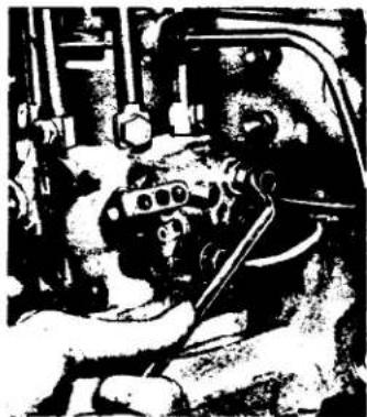
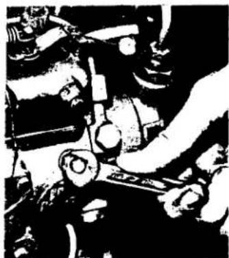
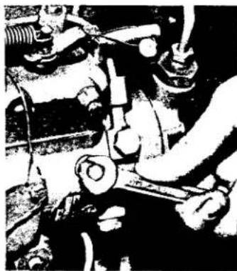
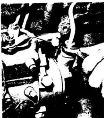
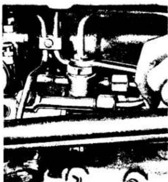
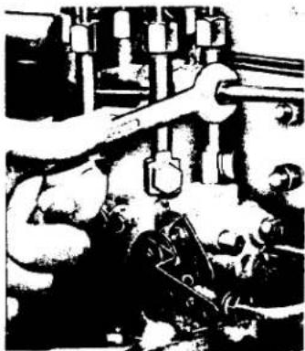
- Loosen the air vent screw on the side of the governor housing (refer to fig.8(a) (b) (c) (d) (e) NOTE: Two wrenches may be required for 6.354 engines if the screw is coated with paint.
2 Loosen the vent attached to one of the two hydraulic head locking screws. Refer to figs. 8(f) (g) (h) (i). Unscrew vent plug on top of fuel filter (if equipped). - Operate priming lever on fuel transfer pump (if this is not possible, the camshaft driving the pump lever may be on maximum lift; turn engine one revolution) and when fuel, free from air bubbles, issues from each venting point, tighten the screws in the following order:
- Fuel Filter Cover Vent Screw.
- Head Locking Screw.
- Control Gear Vent Screw.
- Slacken the pipe union nut (See fig. 8(j) (k) (l) at the pump inlet, operate the priming lever and retighten when fuel free from air bubbles, issues from around the threads.
- Slacken union nuts at the injector ends of two of the high pressure pipes.
natural_image
Black-and-white photo of a hand operating machinery in a vehicle (no visible text or symbols)Fig 8 (a) 4.108
For newer engines see 11(d)
natural_image
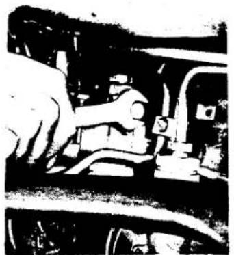
Black-and-white photo of a person operating a mechanical device with no visible text or symbolsFig. 8 (b) 4.154
natural_image
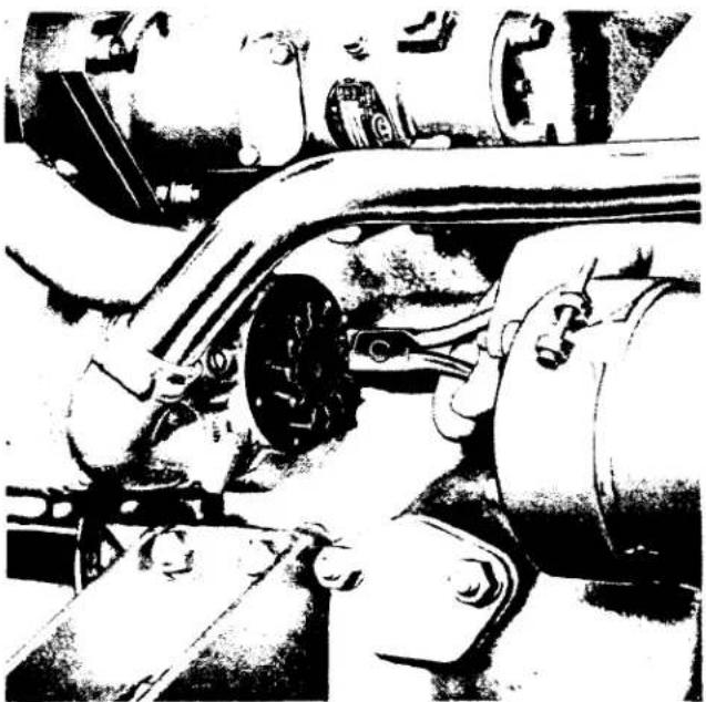
Black-and-white illustration of an engine assembly with visible components and wiring (no text or symbols)Fig. 8 (c) 6.354, T6.354

natural_image
Black-and-white photo of a person operating machinery with no visible text or symbolsnatural_image
Black-and-white illustration of a mechanical device with no visible text or symbolsFig. 8 (e) 4.236
natural_image
Black-and-white photo of a person working on machinery with tools and equipment (no visible text or symbols)Fig. 8 (f) 4.236
- Set throttle at the fully open position (ensure stop/run lever is in run position).
- Turn engine with starter until fuel, free from air bubbles, issues from both fuel pipes.
- Tighten the union nuts on both fuel pipes. The engine is ready for starting.
natural_image
Mechanical assembly diagram showing a bolted joint with bolts and shafts (no text or labels)Fig. 8 (g) 4.108
natural_image
Industrial machinery setup with rollers and mechanical components (no visible text or symbols)Fig. 8 (h) 6.354 (all)
natural_image
Mechanical assembly diagram showing a hand operating a vehicle chassis with no visible text or symbolsFig. 8 (i) 4.154
natural_image
Black-and-white photo of a person in motion, possibly a robot or vehicle, with no visible text or symbols.Fig. 8 (j) 4.236 & 4.154
natural_image
Close-up of industrial machinery components (no visible text or symbols)Fig. 8 (k) 4.108
natural_image
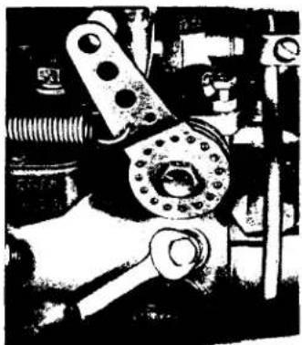
Black-and-white illustration of industrial machinery with workers and pipes (no visible text or symbols)Fig. 8 (I) 6.354 (all)
V8.510 Engines equipped with in-line fuel injection pumps
- Unscrew final filter vent plug (see fig. 9 (a)).
- Unscrew the two vent plugs or vent screws on the fuel injection pump by two or three turns. These plugs are located on each side of the fuel inlet connection on the right hand side of the pump (See fig. 9)b).
- Operate priming lever on the fuel transfer pump. If the transfer pump driving cam is on maximum lift, it will not be possible to operate the hand primer. If so, turn the engine through one revolution and proceed.
When fuel free from air bubbles, issues from the venting points, tighten the fuel filter vent plug and then the fuel injection pump vent plugs.
natural_image
Black-and-white illustration of a mechanical assembly with gears and shafts (no visible text or symbols)Fig. 9 (a)
natural_image
Mechanical assembly diagram showing intersecting rods and components (no visible text or labels)Fig. 9 (b)
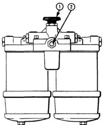
Fig. 9 (c)
- Idling Speed Adjusting Screw
- Fuel Pump Return Connection
Engines equipped with S.I.G.M.A. rotary type fuel injection pumps
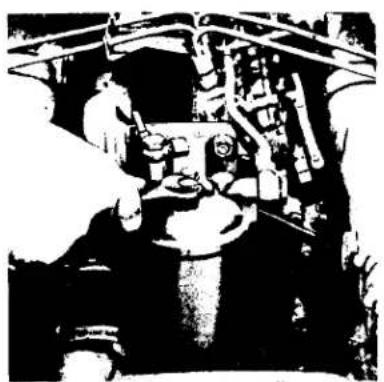
- Unscrew the vent plug on the front of the fuel filter (see fig. 9 (c) two or three turns.
- Unscrew the priming pump handle on the top of the filter and operate the pump until fuel, free from air bubbles, issues from the connection. Tighten the connection.
- Screw the priming pump handle securely back into the filter head casting.
- Slacken the unions at the injector end of two of the high pressure pipes.
- Place the accelerator in the fully open position and turn the engine with starter until fuel, free from air bubbles, issues from both pipes.
- Tighten the unions of the fuel pipes. The engine is ready to start.
FUEL FILTERS
Two fuel filters are usually installed on Perkins Marine Engines, one in the fuel transfer pump and the other, a self contained unit with renewable element, mounted on the engine. 4.108 engines do not have a filter in the fuel transfer pump. A fine wire mesh filter within the fuel tank filter and a water trap between the tank and transfer pump are highly recommended to pre-filter the fuel.
To renew filter elements
- Clean exterior of filter assembly.
- Unscrew setscrew at top of filter head (see fig. 10 (a)).
- Lower base and discard element (see fig. 10(b)).
- Clean filter head and base in suitable cleaning fluid.
- Install sealing rings.
- Install new element in base.
- Place square against filter head and tighten setscrew.
- Bleed fuel system as described previously.
natural_image
Black-and-white illustration of a winged figure standing on a curved structure (no text or symbols visible)Fig. 10 (a)
natural_image
Black-and-white photo of an industrial mechanical assembly with pipes and components (no visible text or symbols)Fig. 10 (b)
natural_image
Technical illustration of a mechanical assembly with hands installing components (no text or symbols visible)Fig. 10 (c)
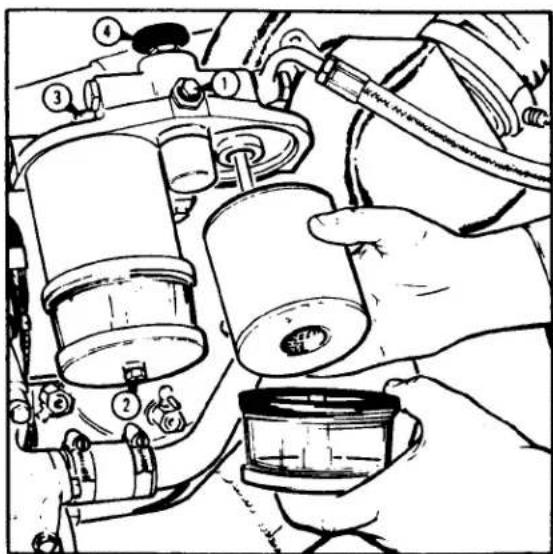
To Renew Final Fuel Filter Elements TV8.510 (M)
Both elements should be changed at the same time, as follows:
- Thoroughly clean exterior of filter assembly.
- Unscrew vent plug (1, Fig 10(c)) by two or three turns and drain filter by releasing drain plugs (2, Fig. 10(c)).
- Unscrew filter bowl securing setscrews at top of filter (3, Fig. 10 (c)) remove bottom covers and transparent bowls and discard elements. Ensure, when removing elements, that no fuel is allowed to leak onto the engine.
- Thoroughly clean filter head, bottom covers and transparent bowls in a suitable cleaning fluid.
- Inspect sealing rings and renew, if damaged in any way.
- Place bottom covers, transparent bowl and new elements together, position these assemblies squarely under the filter head and secure with their retaining setscrews.
- Reinstall drain plugs in bottom covers.
- Unscrew priming pump handle (4, Fig. 10 (c)) from filter head and operate pump until fuel, free from air bubbles, issues from filter vent point.
- Tighten vent plug and screw pump handle into filter head.
IDLING SPEED SETTING
C.A.V. Rotary Type Pumps
D.P.A. pumps have three types of adjustment. The first type is a spring loaded screw (6.354). The second is on the reversible governor head and consists of a setscrew and locknut. The third is on the governor housing (mechanically governed type pump) and consists of a nut and setscrew.
For the first type, turn the screw clockwise to increase engine speed or anti-clockwise to decrease (see fig. 11 (a)).
For the second type, undo the locknut and set the speed (see fig. 11(c) and 11(d)). This must be done in conjunction with the setting of the anti-stall device (see page 51).
For the third type, undo the locknut and set the required speed.
S.I.G.M.A. Rotary Type Pumps (TV8.510 (M))
The idle speed adjustment screw is shown in fig. 9 (d).
In-Line Pumps
The idle adjustment screw is the upper of the two adjustable stop screws situated at the right hand rear of the fuel injection pump (V8.510 (M) engines, Fig. 11 (b)).
The idling speed will vary according to application. For details, inquire at the nearest Perkins, C.A.V. or Simms distributor. (Or Perkins Engines Service Department: Wayne, Michigan or Rexdale, Ontario).
natural_image
Black-and-white photo of people gathered around a table with objects, possibly in a meeting or industrial setting (no visible text or symbols)Fig. 11 (a)
natural_image
Industrial machinery setup with numbered components (no visible text or symbols)Fig. 11 (b)
ANTI-STALL DEVICE
S.I.G.M.A. Rotary Type Pump (TV8.510 (M))
There is no anti-stall device incorporated in this type of fuel injection pump.
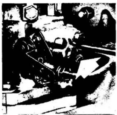
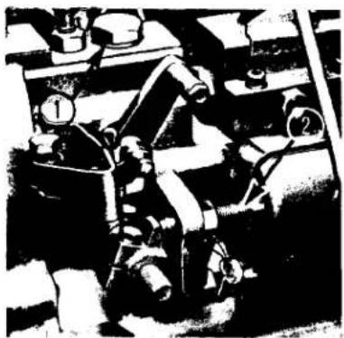
C.A.V. DPA Rotary Type Pumps
- Slacken locknut (2 or 7) sufficiently to enable the anti-stall adjusting screw (1 or 6) to be unscrewed two complete turns.
- Adjust idling speed to 625 rpm* with idling adjustment screw (4 or 2).
- Screw down anti-stall adjusting screw (1 or 6) until there is a very slight increase in engine speed, bring back half a turn and lock with lock nut (2 or 7).
- Accelerate engine to maximum no load rpm and immediately return to idle (See page 32).
Should the period of return from maximum rpm to idle exceed three seconds, the device has been turned too far.
*This idle speed may vary according to application. If in doubt, refer to your nearest Perkins Distributor.
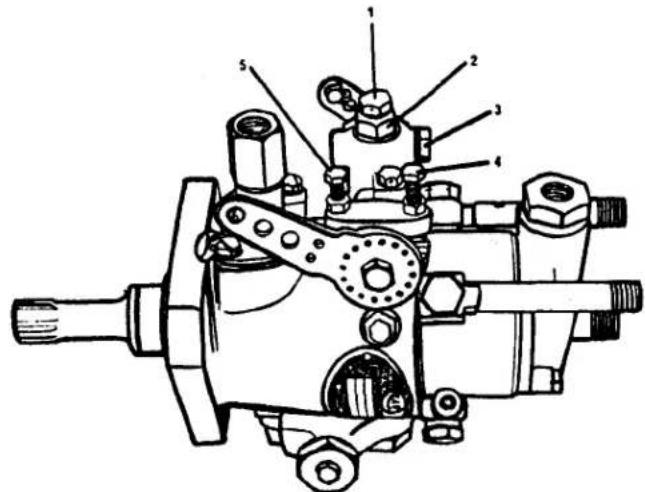
Fig. 11 (c) Earlier Fuel Pump
- Anti-stall adjusting screw
- Idle adjustment screw
- Anti-stall locknut
- Maximum speed screw
- Air vent screw
If the engine stalls out, the device has not been turned in far enough. The necessary adjustment should be made to overcome either situation.

Do not attempt to adjust the maximum speed screw (5). This is a factory adjusted setting that requires special test equipment. If the setting is altered, the result may be severe engine damage.
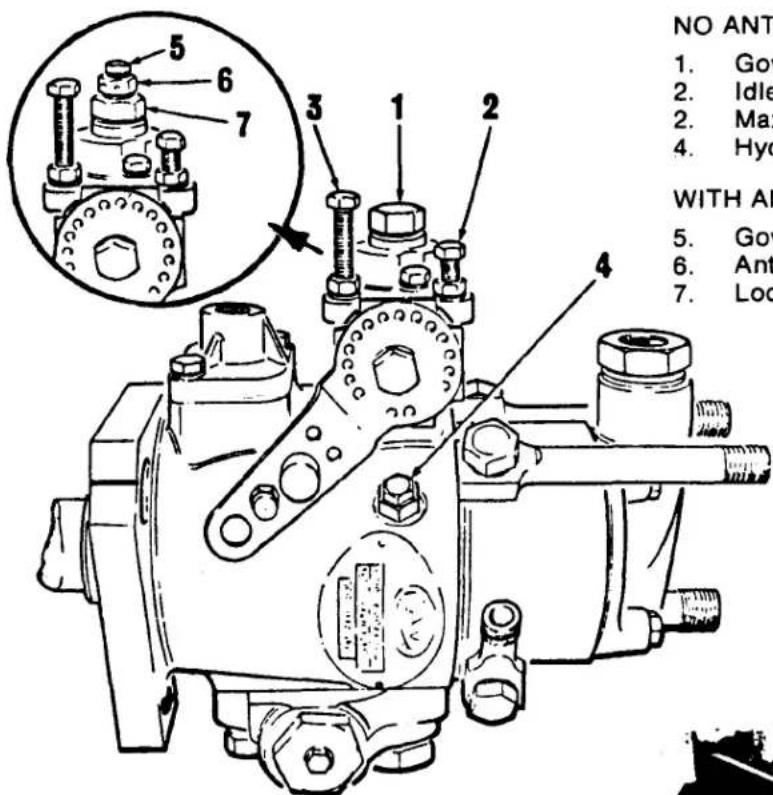
- Governor Housing Bleed Screw
- Idle Adjustment Screw
- Maximum Speed Screw
- Hydraulic Head Bleed Screw
WITH ANTI-STALL DEVICE
- Governor Housing Bleed Screw
- Anti-stall Adjusting Screw
- Locknut
natural_image
Black-and-white illustration of a mechanical device with no visible text or symbolsFig. 11 (e)
In-Line Pumps
- Screw out anti-stall device by two or three turns (refer to fig. 11 (e) for V8.510 engines).
- With engine warmed up, adjust idle speed adjustments for 500 rpm.
- Screw in the anti-stall device until it just affects idle speed. Back out 34 turn and lock with locknut.
- Operate speed control lever and check to ensure that the anti-stall device is not influencing the idle speed setting and that the engine does not stall out when the lever is quickly closed.
C.A.V. Thermostat Device
Two different types of C.A.V. Thermostarts are installed on Perkins engines. The discontinued type, Mark I, is still in use with older engines while the current type, Mark III, is widely used with newer engines.
Bleeding the Thermostat:
The Mark III device incorporates a heat sensitive bi-metallic element to open and close the fuel inlet valve. If the device is used "dry" (i.e., without fuel) the bi-metallic element will become distorted because of the excessive heat and thereafter will not function properly to shut off the fuel. The result of unmetered fuel entering the combustion chambers will be difficult starting, black exhaust smoke and additional engine noise. Also, it can cause hydraulic lockup, which can, in turn, cause the connecting rods to be bent.
In consideration of the consequences described above, it is imperative that before attempting to start a new engine or an engine having any part of its low pressure fuel system dismantled, the fuel system and the fuel line to the Thermostat device must be "bled" to ensure fuel availability.
To "bleed" the fuel system-
- Loosen the air vent screw on the injection pump governor control housing.
- Loosen the hydraulic head vent screw on the side of the injection pump body.
- Loosen the vent plug on the top of the primary fuel filter.
- Operate the fuel transfer pump priming lever until fuel free from air bubbles issues from each venting location. While continuing to operate the lever, tighten the screws in the following order.
a) Primary fuel filter vent screw.
b) Hydraulic head vent screw.
c) Governor vent screw.
-
Loosen the fuel line connection at the inlet to the Thermostat device.
-
Operate the fuel lift pump priming lever until fuel free from air bubbles issues from the loosened connection. While continuing to operate the lever, tighten the connection.
INJECTOR TESTING AND REPLACEMENT
Normally, defective injectors can be isolated by loosening the pipe union nut on each injector in turn while the engine is running at approximately 800 rpm. As each nut is loosened, fuel will not be injected into the associated cylinder and, as a result, the engine rpm will decrease if the injector was previously functioning normally. If the engine rpm remains constant, the injector is probably defective.
When installing a replacement injector remember to also include a new copper seating washer. These are special washers and ordinary washers can not be used for this purpose. The recess in the cylinder head, the faces of the washer and the corresponding face of the nozzle holder cap must be perfectly clean to ensure a leak proof seal. The importance of injectors being seated squarely and secured with the correct torque cannot be emphasized too strongly. Even a slight "canting" of the injector can result in fouling and distortion of the nozzle and needle valve. This canting can also result in leakage between injector and cylinder head, with a resultant engine mis-fire.
TORQUE - To ensure squareness and free entry of the nozzle into its bore, the securing nuts must be tightened evenly until a torque of 12 lbf ft (1.7 kgf m) is attained. Overtightening of these securing nuts can result in a fractured injector flange and/or a fouled nozzle needle valve.
TIGHTENING HIGH PRESSURE FUEL PIPE NUTS
Fuel leakage from high pressure pipe unions will result if the nuts are over-tightened. Excessive torque can cause the ferrule (olive) and/or the collar of the nut to be damaged. The correct torque is 12/15 lbf ft. (1.7 - 2.0 kgf m)
If a high pressure pipe union leaks fuel because the nut has not been tightened sufficiently, the nut should only be tightened enough to stop the leak.
COOLING SYSTEM
Two types of cooling systems are employed on Perkins marine engines, i.e., indirect and keel cooling.
Indirect Cooling: This system incorporates a heat exchanger, coolant in a closed circuit and raw (sea) water used as the cooling medium. The raw water discharge can be routed into the exhaust silencing system. A thermostat in the closed circuit system keeps the engine at an operating temperature of 150 - 200°F (65 - 93°C) for 4.108 engines and 168 - 197°F (75 - 91°C) for the remainder of the marine engine range. Two water pumps are used.
Keel Cooling: This is the same system as above except the dissipation of heat is accomplished by pipes located outside the hull, usually at an angle between the keel and the garboard strake. The length and diameter will be determined by the engine requirements.
Coolant Capacities: Heat Exchanger System
4.108 (M)
V8.510 (M), TV8.510 (M)
9.3 U.S. Gallons (35.2 Litres)
4.236
3.5 U.S. Gallons (13.25 Litres)
This type of pump is used for raw water circulation.
The pump should never be run in a dry condition (impeller blades will tear) and, if the engine is not to be operated for any length of time, it will be necessary to pack the water pump with MARFAK 2HD grease. (If this is not available, glycerine may be used). This is effected by removing the pump end plate* to give access to the interior of the pump. Insert the grease, or glycerine, through the top-most pipe connection (after removing the rubber hose). Turn the engine over to spread the lubricant. This treatment is usually effective for about three months and should be repeated if stored for a longer period of time.
*Refer to Page 43.
With 4.154 marine engines, the raw water pump will have to be removed from the engine to gain access to the end plate.
NOTE: ALWAYS KEEP A SPARE IMPELLER ON BOARD
Fig. 12, Typical Heat Exchanger Cooling System Using Separate Heat Exchanger and Engine Oil Cooler.
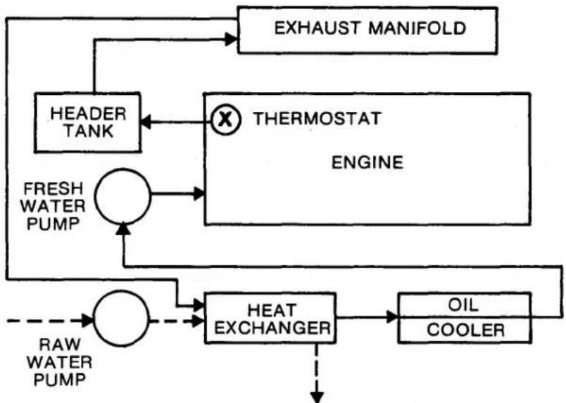
flowchart
graph TD
    A["EXHAUST MANIFOLD"] --> B["HEADER TANK"]
    B --> C["THERMOSTAT ENGINE"]
    C --> D["FRESH WATER PUMP"]
    D --> E["HEAT EXCHANGER"]
    E --> F["OIL COOLER"]
    F --> G["RAW WATER PUMP"]
    G --> H["HEATER TANK"]
    H --> I["EXHAUST MANIFOLD"]
Heat Exchangers, Oil Coolers and Air Charge Coolers
A heat exchanger usually consists of a casing with a core (tube stack), which is the actual heat exchanger. The oil cooler usually has a smaller core and is sometimes an integral part of the engine heat exchanger.
The heat exchanger and coolers should be serviced every season. However, it is stressed that, depending on operating conditions, this period may have to be reduced. Although the coolant temperatures of new engines cease to fluctuate after a short period of operation, the stabilized (normal operating) temperatures will vary slightly from engine to engine because of design tolerances, installation and hull variations. Once the normal operating temperature has been established for a particular engine, any excessive rise in temperature should be considered abnormal and immediately investigated. If a cooling system problem is suspected (or confirmed) the following guidelines will provide a means for isolating the cause.
-
Check the coolant level in the header tank and ensure the proper pressure cap is being used (7psi or .492 kgf/cm2). The coolant in an operating or recently stopped engine is very hot and under pressure. If the filler pressure cap is suddenly removed the liquid may spurt and cause injury by scalding. Always stop an engine and allow it to cool before removing the cap. Once cool, loosen the cap slowly to relieve the pressure.
-
Check the sea cock and strainer for obstructions - clean where necessary.
-
Check the sea water pump impeller-renew if damaged. Ensure that no pieces of the impeller (if broken) have passed into the connecting pipes (i.e., inlet and outlet) because, if so, they could restrict water flow.
-
Check all heat exchangers (coolers) for obstructions within the cooling core tubes on the sea water side. Once the end cap and/or plates are removed, any minute scaling within the core tubes can be removed by passing a rod (slightly smaller than the internal bore) through the tubes. Do not use excessive force when pushing the rod through the tubes.
If the tubes are so clogged that a rod can not be passed through them, the core will have to be removed from its casing and boiled in a caustic soda solution. Commercial cooling system cleaners can be used for this purpose, providing they are recognized as being acceptable by the heat exchanger manufacturer. Reassemble with new gaskets, seals and "O" rings.
If a reduced power and/or excessive smoke condition exists in addition to an increase in coolant temperature with a turbocharged engine having an air charge cooler (intercooler), check the intercooler and, if necessary, clean as described for heat exchangers.
-
Check - especially if the engine was operated in muddy or silty water - the exhaust manifold outlet elbows and the exhaust water injection connections for mud or silt restrictions.
-
Oil Coolers - both engine and gear box - can also effect engine coolant temperatures. Oil coolers should be checked and cleaned as described for heat exchangers.
-
It is particularly important for TV8.510 marine engines to check the last cooler in the sea water system - usually the gear box oil cooler - for water flow restrictions. This cooler should be checked any time there is suspicion of a higher than normal temperature and, in addition, it should be checked at least yearly with seasonal weekend cruising and twice yearly with extended cruises.
Water Pump Drive Belts
Check the tensions of the sea (4.154 M) and fresh water pump drive belts. When correctly adjusted, the depression of the belt by the thumb between water pump and crankshaft pulley should be approximately 38 " (10 mm).
Seacocks and Strainers
Ensure that seacocks are open prior to starting the engine and that, after the engine has started, there is a flow of water from the discharge pipe. The interval between the cleaning of the strainer is left to the discretion of the operator but regular checks should be made to ensure there are no restrictions. Fig. 13 depicts a typical seacock.
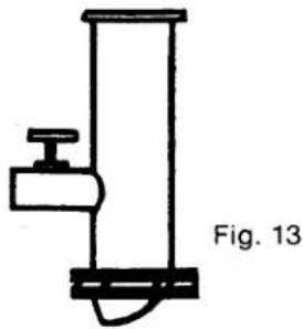
natural_image
Simple line drawing of a vertical cylindrical object with a side knob and base, labeled Fig. 13 (no text or symbols on the object itself)Thermostats
The thermostat, by controlling engine operating temperature within a given range, plays an important part in the operating efficiency and life of an engine. Therefore it is essential that it functions correctly at all times.
LUBRICATING SYSTEM
The importance of correct and clean lubrication cannot be stressed too highly. Care should be taken in the selection of oil to ensure that it is correct for the climatic conditions. The oil pan should be filled to the correct level but DO NOT overfill above the full mark.
Because of the variance in delivery of the lubricating oil pump and scavenge pump, the following procedure is recommended for horizontal 6.354 engines when changing the lubricating oil.
- Fill engine oil pan to full mark on the dipstick.
- Run the engine until at normal operating temperature, idle engine for two minutes and shut down.
- Top up oil pan to full mark on dipstick. This replaces residual oil remaining in the crankcase.
For routine oil level checks, horizontal engines should be idled for two minutes before reading the dipstick. The oil level should not be checked with the engine running at speeds in excess of 1000 rpm, or if the engine has been shut down from speeds of over 1000 rpm without the two minutes idling period.
Oil Pressure
Engine oil pressure should be 30/60 psi (2.1/4.2 kgf/cm2) at normal operating speed and temperature. It is normal for the pressure to drop while the engine is idling and when the oil is hot.
Oil Filters
The lubricating oil filter installed on most Perkins marine engines is the screw-on canister type. The canister is secured to the filter head by a threaded adaptor.
Perkins diesel engines require the use of high quality lube oil filters made to Perkins original equipment standards. To protect our customers from filters that do not meet Perkins specifications, we have established minimum performance standards based on SAE oil filter test procedures SAE J806a. The Perkins Wayne Engineering Department maintains a list of filter manufacturers who have supplied test data to SAE J806a and have met Perkins minimum standards. These standards in general preclude the use of low quality, low cost filters.
Renewing Oil Filter
- Clean exterior of filter.
- Unscrew and discard the oil canister.
- Clean the filter head and threaded spigot.
- Pour (slowly) clean engine lub oil into the center of the replacement canister until full*.
- Using clean engine lub oil, lightly oil the top seal of the replacement canister.
- Screw replacement canister onto filter head until the seal just touches head and then tighten by hand a further half turn. If the canister is overtightened, difficulty may be ex-experienced in removal.
- Run the engine and check for leaks. Do not run the engine at high idle until oil pressure has built up. Recheck oil level and top up as necessary.
*It is recommended that before installing a new screw-on filter canister, it should be primed with oil. Clean lubricating oil should be poured slowly in the center threaded orifice, allowing time for the oil to fill the canister through the filter medium. When attaching a canister to a filter head not in the straight-up position, a small quantity of oil in the stack pipe may be spilled before the canister is screwed home onto its seal.
RECOMMENDED ENGINE LUBRICANTS
The recommended engine lubricating oil for naturally aspirated Perkins marine engines is a reputable brand of oil meeting the minimum requirements of U.S. Military Specification MIL-L-46152 when a fuel having a maximum sulfur content of 1.3% by weight is used. This was formerly known as MIL-L-2104B and can be identified by API Service Classification "CC". Lubricating oil for turbocharged engines should meet the requirements of MIL-L-2104C, which can be identified by API Service Classification "CD".
Should questions arise concerning a particular brand of lub oil, consult the supplier.
Synthetic Lubricating Oils
As the result of continuing requests for Perkins approval of synthetic lubricating oils, the following policy is announced:
1. General Policy
Perkins Engines does NOT recommend the use of synthetic lubricating oil for the following reasons:
a. General experience to date shows the potential for excessive engine wear, particularly with reference to piston rings, cams and gears.
b. Experience to date shows the potential for premature seal and other elastomer deterioration.
c. Synthetic oils have been found to be subject to critical quality control requirements. Critical compounding is required and small deviations result in greater than expected performance variations.
d. No major name brands currently have acceptable compounds. The other than name brand suppliers are difficult to identify and evaluate as dependable suppliers.
2. Exceptions to General Policy
Some products on the market are not true synthetic lubricating oils. Instead, they are man-made hydrocarbons (sometimes referred to as "synthesized hydrocarbon"). This type of man-made fluid is the only available oil with a molecular structure having good high temperature properties and yet not containing the waxy materials that interfere with low temperature flow. Because of the properties of these fluids, Perkins makes the following exceptions to its "no synthetic" rule:
a. The fluid must meet or exceed MIL-L-46167 or MIL-L-46152 quality levels.
b. It must be synthesized hydrocarbon oil versus synthetic oil.
c. The customer must request in writing approval for use in a specific geographical location.
d. If lubrication connected wear and/or failure problems develop, the approval may be rescinded.
LUBE OIL SPECIFICATIONS:
(Minimum Viscosity Index of 80)
| ALL ENGINES | |
| NATURALLY ASPIRATED | TURBOCHARGED |
| MIL-L-46152 (API "CC")with200 hr.Oil Change Period | MIL-L-2104C (API "CD")with200 hr. Oil ChangePeriod |
| MIL-L-46152 (API "CC")with100 hr. Oil ChangePeriod | |
VISCOSITY REQUIREMENTS: All engines except 4.108
| TEMPERATURE RANGES DEGREES F. | ENGINE OIL VISCOSITY* |
| Zero to 30 | SAE 10W |
| 30 to 80 | SAE 20W20 |
| 80 and over | SAE 30 |
| 4.108 ENGINES | |
| Zero to 45 | SAE 10W |
| 45 to 80 | SAE 20W20 |
| 80 and over | SAE 30 |
*Multi-viscosity oils may be used providing the viscosity range is compatible with the specified viscosity (e.g., 10W/30 may be used in lieu of 10W oil).
GEARBOXES (TRANSMISSIONS)
The following gearboxes are attached to Perkins engines when supplied from production, but other boxes may be attached by certain boat builders.
| 4.108 | Borg-Warner 71 CR or Paragon |
| 4.154 | Borg-Warner 71 CR |
| 4.236 | Borg-Warner 71 CR or Borg-Warner 72 CR |
| 6.354 | Borg-Warner 72 CR/C or Borg-Warner 71 CR/C |
| T6.354* | Borg-Warner 72 CR/C |
| HT6.354 | Borg-Warner 72 CR/C |
| V8.510 | Borg-Warner 72 CR, 73 CR or Twin Disc MG-502 |
| TV8.510 | Borg-Warner 73 CR or Twin Disc MG-506 |
*Also T6.354 MGT
BORG-WARNER - Procedure for checking fluid level
The fluid level should be checked immediately after shut-down and sufficient fluid added to bring the level to the full mark on the dipstick. The dipstick assembly need not be threaded into the case to determine fluid level. Newer gearboxes have plug type dipsticks.
Filling - Transmission fluid (Type "A") should be added until it reaches the full mark on the dipstick. The unit should be rotated at idling speed for a short time to fill all circuits.
The maximum interval between fluid changes for Borg Warner "Velvet Drive" marine transmission is 400 hours operating time or 12 months (each boating season), whichever occurs first.
The condition of the fluid filter (if equipped) screen should be checked and cleaned if necessary prior to refilling the transmission.
NOTE: Vee Drive, 2.1:1 reduction units and CR-2 Drop Center transmissions do not have filter screens. The filter screen for all other units is located within the cooler return/transmission fluid drain orifice.

Fluid Pressures and Temperatures (71CR/C and 72CR/C)
Fluid Pressures should be 110-150 PSI (7.53-10.55 kgf/cm2) at normal operating temperatures of 150-165°F (65.55-73.8°C). At low temperatures or excessive speeds, pressure may rise to 200-250 PSI (14.06-17.58 kgf/cm2). The maximum recommended fluid temperature is 190°F (87.6°C).
Fluid Pressures and Temperatures (73CR)
Fluid Pressure should be 115-140 PSI (8.08 - 9.84 kgf/cm2) at 2000 rpm engine speed with a fluid temperature of 140-190°F (60-88°C).
Fluid Capacities
| GEARBOX | LEVEL | INCLINED | ||
| U.S. QUARTS | LITRES | U.S. QUARTS | LITRES | |
| 71C & CR 1:1 | 1.8 | 1.71 | 1.3 | 1.2 |
| 1.50:1 | 2.5 | 2.36 | 2.7 | 2.56 |
| 1.91:1 | 2.5 | 2.36 | 2.7 | 2.56 |
| 2.10:1 | 2.5 | 2.36 | 2.7 | 2.56 |
| 2.57:1 | 2.5 | 2.36 | 2.7 | 2.56 |
| 2.91:1 | 2.5 | 2.36 | 2.7 | 2.56 |
| 72C & CR 1:1 | 2.1 | 2.00 | 1.7 | 1.55 |
| 1.50:1, 1.91:1 | ||||
| 2.10:1 | 2.7 | 2.56 | 2.8 | 2.55 |
| 2.57:1, 2.91:1 | 2.7 | 2.56 | 2.8 | 2.55 |
| 73C 1:1 | 2.6 | 2.38 | 1.5 | 1.42 |
| 1.51:1, 2.1:1 | ||||
| 2.9:1 | 2.0 | 1.89 | 2.2 | 2.04 |
BORG-WARNER MODEL DESIGNATIONS
Recently Borg-Warner changed the means for identifying their various transmissions. The following cross reference is being included for identification convenience.
| RATIO | PREVIOUS MODEL DESIGNATION | PREVIOUS MODEL DESIGNATION | NEW DESIGN MODEL DESIGNATION |
| 1:1 | AS1-71C | 10-04-000-036 | 10-17-000-001 |
| 1:1 | AS1-71CR | 10-04-000-037 | 10-17-000-002 |
| 1:1 | AS1-71CB | 10-04-000-038 | 10-17-000-003 |
| 1:1 | AS1-71CBR | 10-04-000-039 | 10-17-000-004 |
| 1.52:1 | AS2-71C | 10-04-000-042 | 10-17-000-005 |
| 1.52:1 | AS2-71CR | 10-04-000-043 | 10-17-000-006 |
| 1.91:1 | AS7-71C | 10-04-000-050 | 10-17-000-007 |
| 1.91:1 | AS7-71CR | 10-04-000-051 | 10-17-000-008 |
| 2.10:1 | AS3-71C | 10-04-000-044 | 10-17-000-009 |
| 2.10:1 | AS3-71CR | 10-04-000-045 | 10-17-000-010 |
| 2.57:1 | AS14-71C | 10-04-000-046 | 10-17-000-011 |
| 2.57:1 | AS14-71CR | 10-04-000-047 | 10-17-000-012 |
| 2.91:1 | AS15-71C | 10-04-000-048 | 10-17-000-013 |
| 2.91:1 | AS15-71CR | 10-04-000-049 | 10-17-000-014 |
| 1:1 | AS11-72C | 10-05-000-034 | 10-18-000-001 |
| 1:1 | AS11-72CR | 10-05-000-035 | 10-18-000-002 |
| 1.52:1 | AS12-72C | 10-05-000-038 | 10-18-000-003 |
| 1.52:1 | AS12-72CR | 10-05-000-039 | 10-18-000-004 |
| 1.91:1 | AS17-72C | 10-05-000-046 | 10-18-000-005 |
| 1.91:1 | AS17-72CR | 10-05-000-047 | 10-18-000-006 |
| 2.10:1 | AS13-72C | 10-05-000-040 | 10-18-000-007 |
| 2.10:1 | AS13-72CR | 10-05-000-041 | 10-18-000-008 |
| 2.57:1 | AS14-72C | 10-05-000-042 | 10-18-000-009 |
| 2.57:1 | AS14-72CR | 10-05-000-043 | 10-18-000-010 |
| 2.91:1 | AS15-72C | 10-05-000-044 | 10-18-000-011 |
| 2.91:1 | AS15-72CR | 10-05-000-045 | 10-18-000-012 |
TWIN DISC MG-502 & MG-506 GEARBOXES
Oils used in this gearbox type must conform with API Service Classification "SD". Any oil that conforms with this specification is suitable. The correct S.A.E. designation to be used will depend upon the temperature of the cooling water at the inlet to the gearbox oil cooler.
| S.A.E. DESIGNATION | |
| Cooling Water Temp.Below 85°F (29°C) | Cooling Water Temp.Above 85°F (29°C) |
| 20W/20 | 30 |
PROCEDURE FOR CHECKING OIL LEVEL
The gearbox oil level should always be checked with the engine running at idle speed.
FILLING
Stop the engine. Fill gearbox to "full" mark on the dipstick with API "SD" engine lub oil.
OIL CAPACITY: 4.8 U.S. Quarts (4.55 Litres)
4.8 U.S. Quarts (4.55 Litres)
OIL PRESSURE
Normal pressure is 300-320 psi (21.1 - 22.5 kgf/cm2) at 1,800 rpm and 180°F (83°C).
Minimum pressure is 270 psi (18.98 kgf/cm2) at cruising speed.
PARAGON GEARBOXES
Procedure for Checking Fluid Level - When the engine is first started, allow it to idle for a few moments. Stop the engine and check the transmission fluid level. Add type "A" transmission fluid, if necessary, to bring the level up to the mark on the transmission dipstick.
Oil Pressure - Normal pressure is 60 psi (4.22 kgf/cm2) at normal operating temperature.
PROPELLER SHAFT TRAILING (FREE WHEELING)
Borg Warner have determined through practical experience that sail boats having Borg Warner transmissions (auxiliary engine installations) can sail with the propeller trailing (free wheeling) at unlimited speeds without risking damage to the transmission, providing the unit is filled with fluid (to full mark on dipstick).
Twin engine power boats having one engine inoperative (shut down) with its propeller free-wheeling are also no longer restricted to a maximum speed or rpm, providing the fluid level is maintained at the full mark on the dipstick.
CHECKING VALVE TIP CLEARANCES
When rotating engines, they should always be turned in their normal direction of rotation, i.e., anti-clockwise when viewing from the gearbox end. The exception is contra-rotating engines, which is clockwise from the gearbox end.
4.108, 4.154 and 4.236 Engines
The clearance is set between the top of the valve stem rocker and arm and should be 0.012 in. (0.30 mm) cold. Refer to Fig. 14 (a).
When setting valve clearances the following procedure should be adopted:
- With the valves rocking on No. 4 cylinder (i.e., the period between the opening of the intake valve and the closing of the exhaust valve), set the valve clearances on No.1 cylinder.
- With the valves rocking on No. 2 cylinder, set the valve clearances on No. 3 cylinder.
- With the valves rocking on No. 1 cylinder, set the valve clearances on No. 4 cylinder.
- With the valves rocking on No. 3 cylinder, set the valve clearances on No. 2 cylinder.
6.354, T6.354 MGT, T6.354 and HT6.354 Engines
The clearance is set between the top of the valve stem and rocker arm and should be 0.012 in. (0.30 mm) cold. Refer to Fig. 14 (a)
When setting valve clearances the following procedure should be adopted.
- With the valves rocking on No. 6 cylinder (i.e., the period between the opening of the intake valve and the closing of the exhaust valve), set the valve clearances on No.1 cylinder.
- With the valves rocking on No. 2 cylinder, set the valve clearances on No. 5 cylinder
- With the valves rocking on No. 4 cylinder, set the valve clearances on No. 3 cylinder.
- With the valves rocking on No. 1 cylinder, set the valve clearances on No. 6 cylinder.
- With the valves rocking on No. 5 cylinder, set the valve clearances on No. 2 cylinder.
- With the valves rocking on No. 3 cylinder, set the valve clearances on No. 4 cylinder.
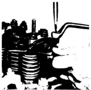
natural_image
Black-and-white illustration of a mechanical assembly with springs and a lever (no text or symbols)Fig. 14 (a)
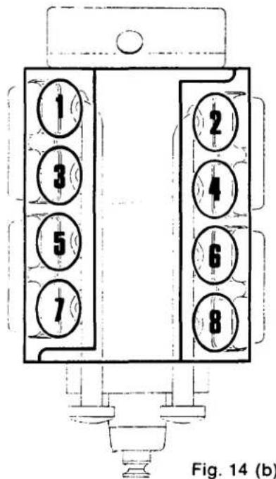
TV8.510 and V8.510 Engines
The clearance is set between the top of the valve stem and rocker arm and should be 0.012 in. (0.30 mm) cold.
When setting valve clearances the procedure below should be followed. Refer to fig. 14 (b) for cylinder numbering.
LEFT BANK
- With the valves rocking on No. 4 cylinder (i.e., the period between the opening of the intake valve and the closing of the exhaust valve), set the valve clearances on No.1 cylinder.
- With the valves rocking on No. 6 cylinder, set the valve clearances on No. 7 cylinder.
- With the valves rocking on No. 2 cylinder, set the valve clearances on No. 5 cylinder.
- With the valves rocking on No. 8 cylinder, set the valve clearances on No. 3 cylinder.
RIGHT BANK
- With the valves rocking on No. 3 cylinder, set the valve clearances on No. 8 cylinder.
- With the valves rocking on No. 1 cylinder, set the valve clearances on No. 4 cylinder.
- With the valves rocking on No. 7 cylinder, set the valve clearances on No. 6 cylinder.
- With the valves rocking on No. 5 cylinder, set the valve clearances on No. 2 cylinder.
ELECTRICAL SYSTEM
Alternator
The alternator has two generating parts, a stator and a rotor. When the rotor rotates inside the stator windings, alternating current (AC) is induced into the stator. This is unsuitable for charging the battery, therefore, a rectification unit comprised of diodes is also built into the alternator. These are connected in such a manner that they provide an output of direct current (DC) for the battery. The alternator output amplitude is controlled by a fully transistorized integral regulator that requires no servicing and is non-repairable. The alternator type and output rating (42 or 61 amp) can be found stamped on the alternator body or identification plate (e.g., 10SI 42A)
GENERAL PRECAUTIONS FOR ALTERNATORS
NEVER disconnect the battery or the starter switch while the alternator is running. This will cause a voltage surge in the system and damage the diodes and transistors.
NEVER disconnect any electrical lead without first stopping the engine and turning all switches to the "OFF" position. ALWAYS identify a lead as to its correct terminal before disconnection. A short circuit or reversed polarity will destroy diodes and transistors.
NEVER connect a battery into the system without checking for correct polarity and correct voltage.
NEVER "Flash" connections to check for current flow. No matter how brief the "Flash", the transistors may be destroyed.
NEVER experiment to try to adjust or repair the system unless you have had proper training on alternators, and you have the correct test equipment and technical data.
NEVER ground the field circuit.
NEVER run the alternator if the output circuit is open, (i.e., without an electrical load).
NEVER attempt to polarize an alternator. When using a battery charger disconnect battery cables.
NEVER apply a battery voltage direct to the regulator or alternator field terminals because this will damage the transistors.
ALWAYS disconnect the alternator terminals before carrying out any electrical welding on the boat because the intense magnetic field created by the "make" and "break" of the arc may cause damage to the diodes.
DO NOT check for continuity of the alternator or regulator with insulation testers such as a "Megger", etc.
ALWAYS disconnect the battery before connecting test instruments (except voltmeter) or before replacing any unit or wiring.
STARTER MOTOR
The starter motor has a centrifugally operated mechanical overspeed protection device that releases the pinion from the flywheel when it reaches a predetermined excessive speed.
The solenoid and main switch assemblies are mounted on top (external) of the starter motor housing.
Normally, scheduled maintenance is not required.
The starter motor type is stamped on the housing or nomenclature plate.
BATTERY MAINTENANCE

WARNING: Batteries being charged give off explosive gas. Do not smoke or produce any means for spark ignition. Always ensure that batteries are properly and securely located in an area with adequate ventilation and access for maintenance. In addition, the following guidelines should be adopted:
- Batteries should be isolated (with isolation switch) when not in use.
- Maintain correct electrolyte level (just above the top of the separators).
- Keep batteries clean and dry to avoid possible corrosion and current leakage.
- Ensure battery connections are clean and tight and, to avoid overheating, that the cable size is adequate for the current load.
- Ensure that no current conducting components or attachments are located in close proximity to the battery.
ELECTROLYTIC CORROSION
Corrosion can occur when two dissimilar metals are in contact in the presence of sea water. Care is taken to avoid this in the design of an engine, but different metal types are necessary. Brass or bronze pipe fittings attached to aluminum parts (for example) will result in rapid corrosion. A zinc pencil is inserted into the heat exchanger to assist in the prevention of electrolytic action.
Particular care is necessary when an engine is installed in an aluminum hull. Zinc anodes can be attached to hulls where corrosion cannot be entirely avoided and specialist firms will advise on their use.
Corrosion can also be caused by current leaking from the battery (and other parts of the electrical system) to the hull via the engine or metal attachments.
RADIO INTERFERENCE SHIELDING
Radio interference in the form of noise can be caused by the alternator, starter motor and other engine-driven equipment. In addition, many boats have electronic equipment aboard (e.g., radar) that could create radio interference. To prevent this interference, adequate shielding must be provided, if possible. Stray electronic radiation shielding is a very complex task and for severe problems it is suggested that a specialist in the field of electronics be consulted.
If the engine stops the first thing to do is check that the fuel supply is ON. If the fuel valves or taps are all open, check the fuel level in the tank. If the engine has been run until the fuel tank is completely empty there is a very good chance that there is a lot of dirt in the fuel lines. Change the fuel filter and, after refueling, bleed the system and re-start the engine.
If the engine slows down or loses power, the cause could be something wrapped around the propeller. Always check this first. Check the air intake for obstruction and the engine compartment for a good supply of air. Also, the air intake mesh may be clogged with foreign matter sucked from a dirty engine compartment.
If the engine coolant boils, ease down the throttle and try to ascertain the cause. The first check is the sea cock to ensure an adequate cooling water supply. If satisfactory, check raw water pump operation, the impeller may have failed. If so, replace with the spare impeller. A spare should always be carried on board.
If a serious leak occurs on a high pressure fuel pipe, disconnect and direct the flow into a can or other receptacle, and run on the remaining cylinders. DO NOT attempt to flatten and pipe because this will ruin the fuel injection pump. Leaks in low pressure fuel pipes can be temporarily repaired by the use of heavy duty adhesive tape, hose and clamps.
If an auxiliary engine is required to run while the boat is beating to windward, the boat may heel (see chart) without adverse effect on the lubrication system providing the boat is righted occasionally so that the valve gear can be lubricated.
Maximum Continuous Angle of Heel
| Heel | 4.108 | 4.154 | 4.236 | 6.354 | HT6.354 |
| To Port | 25° | 30° | 30° | 30° | 36° |
| To Starboard | 25° | 30° | 30° | 30° | 23° |
Coolant leaks can normally be temporarily repaired with heavy duty adhesive tape, hose and clamps.
If a serious oil leak occurs, shut down the engine immediately and try to find the cause. Oil leaks are a lot harder to repair temporarily because of the pressure involved. However, if the main flow can be stopped to a drip or dribble, place a can underneath the leak and replenish the engine with new oil (from a spare oil can) at the same rate as the loss.
Drip trays of metal or glass fiber should be used beneath the engine to stop lubricating oil or fuel oil dripping into the bilges. Care must be taken to avoid galvanic action between the drip tray and engine (e.g., a copper tray should not be used under an aluminum alloy oil pan). Remember to keep the drip tray clean because this provides an early indication of leaks.
Maximum Engine Compartment Temperature (all engines): 140°F (60°C)
Maximum Battery Compartment Temperature (all engines): 122°F (50°)
Volume of Air Required Per Engine
| VOL. | 4.108 | 4.154M | 4.236M | 6.354M | T6.354MT6.354MGT | V8.510M | TV8.510M | |
| ft^3/MIN | 105 | 110 | 157 | 250 | 300 | 406 | 365 | 550 |
| M^3/MIN | 3 | 3.1 | 4.45 | 7 | 8.5 | 11.5 | 10.5 | 15.5 |
Maximum Exhaust Back Pressure (measured within 12 inches/305mm of engine manifold)
| Press. | 4.108M | 4.154M | 4.236M | 6.354M | T6.354MT | T6.354MGT | V8.510 | TV8.510 |
| in.Hg | 3 | 3 | 3 | 3 | 1.5 | 1.5 | 3 | 1.5 |
| mm Hg | 76 | 76 | 76 | 76 | 38 | 38 | 76 | 38 |
ON-BOARD TOOLS AND SPARE PARTS
An "on board" tool kit for emergency repairs should be supplemented by:
Hose clamps, assorted
Hose, assorted (flex type useful)
Wire (20 AWG or 12-14 AWG Stranded)
Insulating (electrical) tape
Gasket Compound
Magnet (keep away from compass)
Mechanical fingers
Self-gripping (pipe) wrench
Asbestos Lagging
Low pressure fuel pipe olives (ferrules)
Small hacksaw with spare blade
Assorted files
Heavy duty adhesive tape
The two kits listed below on page 66 are applicable to any Perkins marine engine. The part numbers for these parts are listed in the applicable parts book for each engine. These kits are strictly guidelines and may be varied at the discretion of the owner/operator.
MAJOR KIT
| QTY. | DESCRIPTION | QTY. | DESCRIPTION |
| 1 | Zinc Pencil (Plug) | 1 | Transfer Pump and Gasket |
| 1 | Injector (6 cyl. engines: 2) | 1 | Injector (6 cyl. engines: 2) |
| 1 pkg. | Injector or Seating Washers | 1 pkg. | Injector Seating Washers |
| 1 | Water outlet Gasket | 1 | Water Outlet Gasket |
| 2 | Fuel Oil Filter Elements | 2 | Fuel Oil Filter Elements |
| 2 | Lub Oil Filter Elements | 2 | Lub Oil Filter Elements |
| 1 | Water Pump Belt | 1 | Water Pump Belt |
| 1 | Alternator Belt | 1 | Thermostat |
| 1 | Thermostat | 1 pkg. | Leak-Off Washers |
| 1 pkg. | Leak-Off Washers | 1 pkg. | Leak-Off Olives (Ferrules) |
| 1 pkg. | Leak-Off Olives (Ferrules) | 1 | Sea Water Pump Impeller |
| 1 set | Injection Lines | 4 qts. | Type "A" Transmission Fluid* |
| 1 | Transfer Pump and Gasket | 8 qts. | Engine Lub Oil |
| 1 | Sea Water Pump Kit | ||
| 1 | Top Gasket Set | ||
| 1 | Water Pump Kit | ||
| 4 qts. | Type "A" Transmission Fluid* | ||
| 8 qts. | Engine Lub Oil |
The parts listed above are also offered in kit form by Perkins Engines. Please order from your distributor. Lub oil and transmission fluid must be purchased separately.
*Borg-Warner and Paragon Gearboxes. Twin Disc: Substitute with "SD" engine lub oil.
TROUBLESHOOTING CHART
| TROUBLE | POSSIBLE CAUSE |
| Low cranking speed | 1, 2, 3, 4 |
| Will not start | 5, 6, 7, 8, 9, 10, 12, 13, 14, 15, 16, 17, 18, 19, 20, 22, 31, 32, 33 |
| Difficult Starting | 5, 7, 8, 9, 10, 11, 12, 13, 14, 15, 16, 18, 19, 20, 21, 22, 24, 29, 31, 32, 33 |
| Lack of power | 8, 9, 10, 11, 12, 13, 14, 18, 19, 20, 21, 22, 23, 24, 25, 26, 27, 31, 32, 33 |
| Misfiring | 8, 9, 10, 12, 13, 14, 16, 18, 19, 20, 25, 26, 28, 29, 30, 32 |
| Excessive fuel consumption | 11, 13, 14, 16, 17, 18, 20, 22, 23, 24, 25, 27, 28, 29, 31, 32, 33 |
| Black exhaust | 11, 13, 14, 16, 18, 19, 20, 22, 24, 25, 27, 28, 29, 31, 32, 33 |
| Blue/white exhaust | 4, 16, 18, 19, 20, 25, 27, 31, 33, 34, 35, 45, 56 |
| Low oil pressure | 4, 26, 37, 38, 39, 40, 42, 43, 44, 58 |
| Knocking | 9, 14, 16, 18, 19, 22, 26, 28, 29, 31, 33, 35, 36, 45, 46, 59 |
| Erractic running | 7, 8, 9, 10, 11, 12, 13, 14, 16, 20, 21, 23, 26, 28, 29, 30, 33, 35, 45, 59 |
| Vibration | 13, 14, 20, 23, 25, 26, 29, 30, 33, 45, 48, 49 |
| High oil pressure | 4, 38, 41 |
| Overheating | 11, 13, 14, 16, 18, 19, 24, 25, 45, 47, 50, 51, 52, 53, 54, 57 |
| Excessive crankcase pressure | 25, 31, 33, 34, 45, 55 |
| Poor compression | 11, 19, 25, 28, 29, 31, 32, 33, 34, 46, 59 |
| Starts and stops | 10, 11, 12 |
KEY TO TROUBLESHOOTING CHART
| 1. | Battery capacity low | 31. | Worn cylinder bores |
| 2. | Bad electrical connections | 32. | Pitted valves and seats |
| 3. | Faulty starter motor | 33. | Broken, worn, or sticking piston ring (s) |
| 4. | Incorrect grade of lubricating oil | 34. | Worn valve stems and guides |
| 5. | Low cranking speed | 35. | Overfull air cleaner or use of incorrect grade of oil (oil bath cleaner) |
| 6. | Fuel tank empty | ||
| 7. | Faulty stop control operation | 36. | Worn or damaged bearings |
| 8. | Blocked fuel feed pipe | 37. | Insufficient oil in oil pan |
| 9. | Faulty fuel lift pump | 38. | Inaccurate gauge |
| 10. | Choked fuel filter | 39. | Oil pump worn |
| 11. | Restriction in air cleaner | 40. | Pressure relief valve sticking open |
| 12. | Air in fuel system | 41. | Pressure relief valve sticking closed |
| 13. | Faulty fuel injection pump | 42. | Broken relief valve spring |
| 14. | Faulty injectors or incorrect type | 43. | Faulty suction pipe |
| 15. | Incorrect use of cold start equipment (if equipped) | 44. | Choked oil filter |
| 16. | Faulty cold starting equipment | 45. | Piston seizure/pick up |
| 17. | Broken fuel injection pump drive | 46. | Incorrect piston height |
| 18. | Incorrect fuel pump timing | 47. | Open circuit strainer or week strap blocked |
| 19. | Incorrect valve timing | 48. | Faulty engine mounting (housing) |
| 20. | Poor compression | 49. | Incorrectly aligned flywheel housing or flywheel |
| 21. | Blocked fuel tank vent | 50. | Faulty thermostat |
| 22. | Incorrect type or grade of fuel | 51. | Restriction in water jacket |
| 23. | Sticking throttle or restricted movement | 52. | Loose water pump drive belt |
| 24. | Exhaust pipe restriction | 53. | Gearbox or engine oil cooler choked |
| 25. | Cylinder head gasket leaking | 54. | Faulty water pump |
| 26. | Overheating | 55. | Choked breather pipe |
| 27. | Cold running | 56. | Damaged valve stem oil deflectors (if equipped) |
| 28. | Incorrect tappet adjustment | 57. | Coolant level too low |
| 29. | Sticking valves | 58. | Blocked oil pan strainer |
| 30. | Incorrect high pressure pipes | 59. | Broken valve spring |
INDEX
Air Charge Coolers 55
Alternator 62
Ammeter 30
Anti-Stall Device 51
Battery Maintenance 63
Boost (Turbocharge) 4
Checking Valve Tip Clearances 61
Cold Weather Precautions 45
Cold Weather Starting 32
Coolant Capacities 28,54
Cooling System 54
Air Charge Coolers 55
Bleeding 46
Capacities 28
Heat Exchangers 55
Indirect Cooling 54
Intercooler 54
Keel Cooled Engines 54
Maintenance 54
Rubber Impeller Water Pump 54
Seacocks and Strainers 56
Thermostats 56
Water Pump Drive Belts 56
Water Temperature Gauge .... 30
Cylinder Head Tightening Sequences 40
Cylinder Head Torque 40
Electrical System 62
Alternator 62
Ammeter 30
Battery Maintenance 63
Electrolytic Corrosion 64
Instruments 30
Shielding 64
Starter Motor 63
Stray Electronic Radiation 64
Tachometer 30
Electrolytic Corrosion 64
Emergency Maintenance and Operating Tips 64
Engine Identification 7
New Format 10
Engine Number Location 6
Engine Photographs 12
Engine Preservation 42
Engine Specifications 28
Fluid Levels, Pressures and Temperatures 59
Fuel Filters 49
Fuel Oil Specifications 45
Fuel System 45
Bleeding 46
Filters 49
Idle Speed Setting 50
Preservation Oil 44
Specifications 45
Gearboxes (Transmissions) 59
Borg-Warner 59
Capacities 60
Fluid Level 59
Fluid Type 59
Oil Specification 60
Pressures 60
Paragon 61
Temperatures 60
Twin Disc MG-502, MG-506 59
General Precautions for Alternators 63
Heat Exchangers 55
High Pressure Fuel Pipe Nuts 53
Indirect Cooling 54
Idle Speed Setting 50
Initial Operating Checks 31
Injector Testing and Replacement 53
In-Line Fuel Injection Pumps 48
Instruments 30
Intercooler 55
Introduction 4
Lub Oil Specifications 58
Lubricating System 56
Capacities 28
Filters....57
Gauge, Pressure 30
Oil Coolers 55
Oil Level, Checking 56
Pressure, Oil 56
Recommended Engine Lubricants ....57
Renewing Oil Filters 57
Specifications 58
Synthetic Lub Oils 57
New Format, Engine Identification 10
Oil Coolers 55
Oil Filters 57
Oil Pressure 56
Oil Pressure Gauge 30
Oil Recommended for Preservation of Fuel System 44
On-Board Tools and Spare Parts 65
Operating Precautions 32
Preparation for Starting 31
Paragon Gearboxes 61
Perkins Diesel Four Stroke Cycle 4
Preparing Engine for Operation 44
Pressures and Temperatures, Gearbox 60
Propeller Shaft Trailing (Free Wheeling) 61
Recommended Engine Lubricants 57
Renewing Fuel Filters 49
Renewing Oil Filters 57
Rubber Impeller Type Water Pump 54
Safety Precautions 5
Schedule Maintenance 34
Seacocks and Strainers 56
S.I.G.M.A. Rotary Type Fuel Injection Pumps 48
Starter Motor 63
Starting and Stopping Engine 31
Stopping Engine 33
Stray Electronic Radiation Shielding 64
Synthetic Lub Oils 57
Tachometer 30
Thermostats 56
Tightening High Pressure Fuel Pipe Nuts 53
Torque....53
Troubleshooting Chart 67
Twin Disc MG-502, MG-506 59
Valve Tip Clearances, Adjusting 61
Water Pump Drive Belts 56
Water Temperature Gauge ....30