BLM200 - Printer Océ - Free user manual and instructions
Find the device manual for free BLM200 Océ in PDF.

| Product Type | Printer |
| Brand | Océ |
| Model | BLM200 |
| Dimensions (W x D x H) | Approx. 500 x 400 x 300 mm |
| Weight | Approx. 15 kg |
| Power Supply | 100-240 V AC, 50/60 Hz |
| Print Technology | Laser |
| Functions | Print, Copy, Scan |
| Print Speed | Up to 30 ppm (black) |
| Print Resolution | Up to 1200 x 1200 dpi |
| Paper Input Capacity | 250 sheets |
| Paper Output Capacity | 150 sheets |
| Connectivity | USB 2.0, Ethernet |
| Maintenance | Replace toner cartridge, clean rollers |
| Safety Features | Overheat protection, auto shut-off |
| Spare Parts Available | Toner cartridge, fuser unit, transfer belt |
| Repairability Index | 8/10 (user-replaceable consumables) |
| General Information | Designed for high-volume office printing |
Frequently Asked Questions - BLM200 Océ
User questions about BLM200 Océ
0 question about this device. Answer the ones you know or ask your own.
Ask a new question about this device
Download the instructions for your Printer in PDF format for free! Find your manual BLM200 - Océ and take your electronic device back in hand. On this page are published all the documents necessary for the use of your device. BLM200 by Océ.
USER MANUAL BLM200 Océ
© 2007, Océ-Technologies B.V. Venlo, The Netherlands.
All rights reserved. No part of this work may be reproduced, copied, adapted, or transmitted in any form or by any means without written permission from Océ.
Océ-Technologies B.V. makes no representation or warranties with respect to the contents hereof and specifically disclaims any implied warranties of merchantability or fitness for any particular purpose.
Further, Océ-Technologies B.V. reserves the right to revise this publication and to make changes from time to time in the content hereof without obligation to notify any person of such revision or changes.
Contents
Chapter 1
Introduction 7
What you can do with this machine 8
Guide to components.... 10
Booklet maker.... 10
Trimmer....12
SquareFold module.... 14
Control panel.... 15
Chapter 2
Basics.... 17
Turn on/off the power.... 18
Check staples, staple cartridge and stapler head 19
Remove/replace staple cartridge 19
Remove/replace stapler head 22
Empty the trim bin 25
Chapter 3
Make booklets 27
Change settings. 28
General procedure 28
Set the paper size.... 29
Select standard paper sizes. 29
Custom paper size 30
Staple and Fold. 31
Select stapling mode 31
Adjust staple and fold alignment 32
Adjust fold quality.... 33
Set up narrow width paper sizes 35
Trim 36
Select trim on or off.... 36
Adjust the cutting margin. 37
SquareFold module 38
General 38
Select the SquareFold module mode 39
Rotator module for Océ VarioPrint 2090, 2100, 2110, 3070, 3090, 3110 and
6250 printers.... 40
General 40
Installation. 42
Basic information. 43
Basic operation 46
Prepare the rotator module. 46
Storage compartment. 48
Maintenance 49
Cleaning 49
Problem solving. 51
"Not Ready" Status indicator 51
Clear paper jams 52
Online/Offline 53
Chapter 4
System administration 55
The Admin screen 56
Language 56
Size standard 57
Service 58
Chapter 5
Job control....59
Store a job 60
Recall a job 61
Chapter 6
Clear a paper jam. 63
General 64
Booklet maker 65
Trimmer input area. 66
Trimmer exit area 68
SquareFold Module 70
SquareFold Module exit area.... 71
Chapter 7
Troubleshooting 73
Fault codes.... 74
General 74
Booklet maker fault codes.... 75
Booklet quality fault 76
Trimmer fault codes.... 77
SquareFold module fault codes.... 78
Chapter 8
General remarks 81
Do's and don'ts 82
Place the machine 84
Maintain the machine 86
Booklet maker.... 86
Trimmer....87
SquareFold module.... 88
Chapter 9
Specifications 91
Machine Specifications 92
Booklet maker Océ BLM200 92
Trimmer BLT6289 / BLT6789 (option) 94
SquareFold module SFM6204 / SFM6704 (option) 95
Rotator RTM6240 (option) 96
Chapter 1 Introduction
What you can do with this machine
Introduction

natural_image
Industrial machine with four numbered compartments and a paper outlet (no visible text or symbols)| Number Description |
| 1 Océ BLM200 booklet maker |
| 2 Trimmer(Model BLT6289) |
| 3 SquareFold module (Model SFM6204) |
| 4 Belt Stacker |
| 5 Rotator module (RTM6240) |
The booklet maker Océ BLM200, Trimmer and SquareFold module form a booklet making system that works online with copiers or printers.
The print-outs from the copier or printer are transported sheet by sheet into the Océ BLM200 booklet maker and collected in the stapler area of the Océ BLM200 booklet maker. The booklet maker now jogs and then staples the set. The set is then transported further to the folding area where the set is folded into a booklet and then fed out to the belt stacker. When a larger number of sheets are folded an effect called creeping occurs. In order to rectify creep, the Trimmer can be connected to the booklet maker. The booklets are then transported from the booklet maker into the Trimmer where the front edge (face) will be cut off. Another option, the SquareFold module, can be installed if a Trimmer is installed on the Océ BLM200 booklet maker. The prints, which have been stapled, folded and trimmed will be fed into the SquareFold module. The SquareFold module will flatten the spine of the booklet into a square shape. The booklets will, after passing through the SquareFold module, have the look of a perfect bound book.
The booklets are then fed out to the belt stacker.
The buttons of the control panel
The entire Océ BLM200 booklet making system is controlled from a single control panel on the booklet maker. The control panel has only six buttons which will allow you to easily set up, adjust and operate the complete system.
| Description | |
 | The buttons are multi functional, meaning that the function of each button depends on the information displayed. For example: In this screen, the icon next to button 1 indicates you will go up one level in the menu when the button is pressed. |
 | Example 2: In this screen, button 1 has no function. |
 | Example 3: Pressing button 1 here will answer “No” to the question on the screen. |
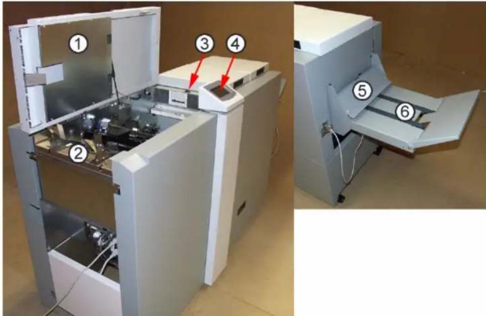
Guide to components
Booklet maker
Component locator
text_image
Technical diagram of a laboratory instrument with numbered parts and labeled components| Number Component |
| 1 Top cover |
| 2 Infeed assembly |
| 3 Power switch |
| 4 Control panel |
| 5 Belt Stacker Cover |
| 6 Belt Stacker |
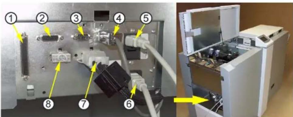
text_image
Technical diagram showing labeled components of an electronic device with numbered parts and a close-up view of the internal device.| Number Component | |
| 1 Communication with Printer/Rotator | |
| 2 Stacker | |
| 3 CAN In: Termination socket | |
| 4 CAN Out: Termination socket / Communication with Trimmer | |
| 5 Power socket | |
| 6 Power out to SquareFold module | |
| 7 Interlock jumper | |
| 8 Interlock jumper / Power out to Trimmer | |
text_image
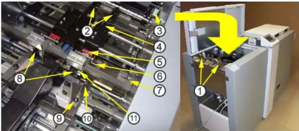
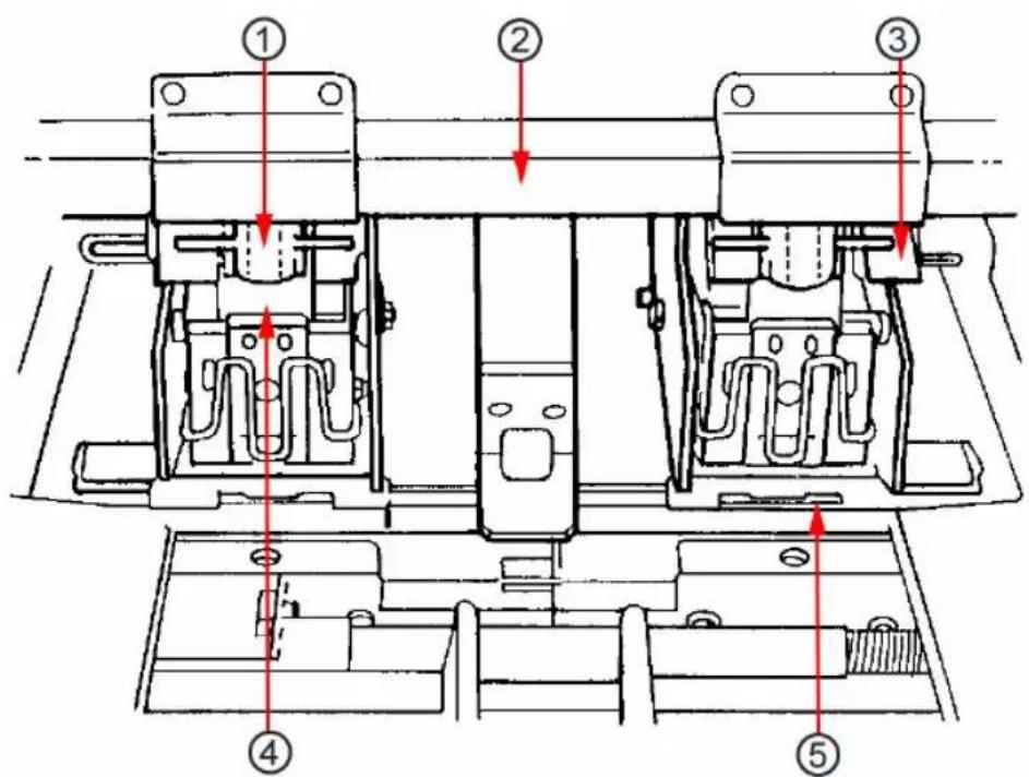
Technical diagram of a machine assembly with numbered components and yellow directional arrows indicating flow or movement.| Number Component | |
| 1 Side guides | |
| 2 | B a 1 1 c a |
| 3 Fold adjust lever | |
| 4 Thumb screw for Stapler assy | |
| 5 Cartridge locking levers | |
| 6 Locking pin | |
| 7 Staple detection leads | |
| 8 Stapler heads | |
| 9 Side guide extension | |
| 10 Thumb screw for Side guide extension | |
| 11 Stapler lift bracket | |
g
Trimmer
Component locator

natural_image
Exterior view of a large industrial machine with control panel and storage compartments (no visible text or symbols)| Number Component | ||||||
| 1 Top cover | ||||||
| 2 | T | r | i | m | b | i |
n
The Trimmer interior has parts that you will come into contact with if a jam occurs.
text_image
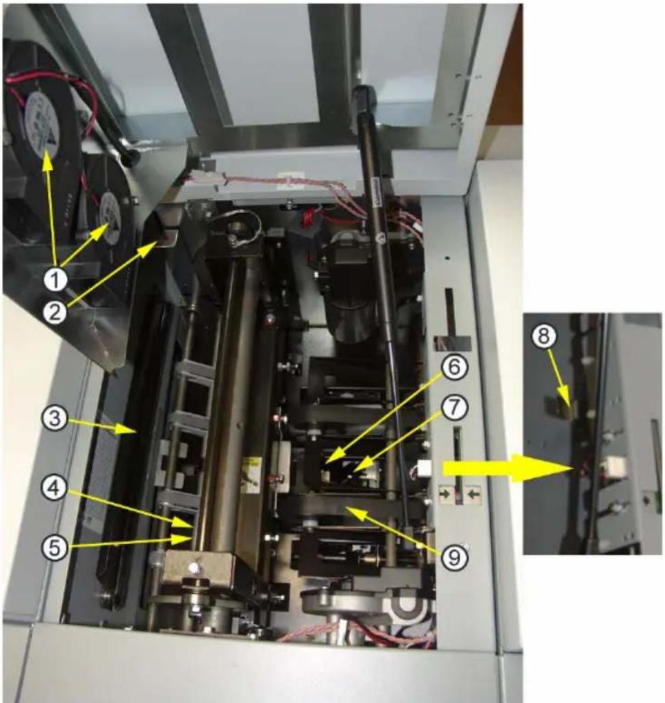
Technical diagram of an industrial machine with numbered components and yellow directional arrows indicating flow or movement.| Number Component | |
| 1 Trimmer fan | |
| 2 Infeed latch | |
| 3 Docking bracket | |
| 4 Infeed roller shaft | |
| 5 Knives (not shown in picture) | |
| 6 Exit compression brackets | |
| 7 Trimmer stop | |
| 8 | O u t f e e |
| 9 Transport belt | |
d
SquareFold module
Component locator
The SquareFold module interior has parts that you will come into contact with if a jam occurs.
text_image
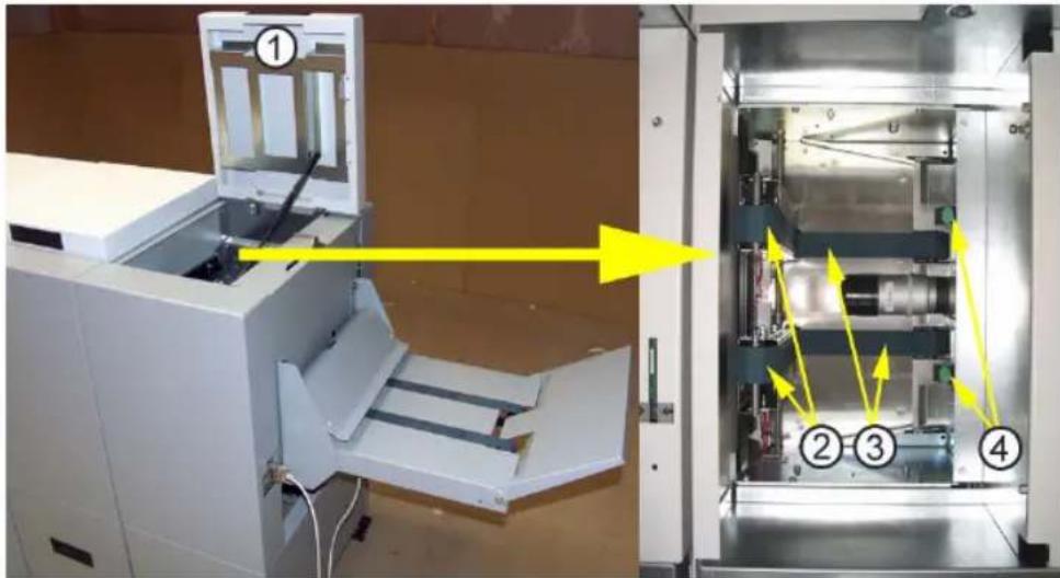
Technical diagram of a machine with numbered components and directional arrows indicating assembly or process flow.| Number Component | ||||||
| 1 Top cover | ||||||
| 2 | U | p | p | e | r | f |
| 3 | L | o | w | e | r | f |
| 4 Latches | ||||||
e
e
Control panel
| Action | |
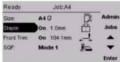
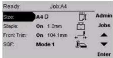
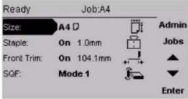 | The Main screen.When the system power is switched on the Main screen will be shown. Here you will find information showing the actual set up. From this screen you can also access other screens, that will help you operate the complete Océ BLM200 Booklet making system.At the top, throughout the screens you can see the current state of the machine and the current job. |
 | Changing settings.To change or adjust settings; Select an item in the Main screen with the [arrow] button and press the [Enter] button. For example you can (finely) adjust the trimming, change stapling mode or set the SquareFold module to the correct mode. Settings are explored more thoroughly in section 2 Making Booklets. |
 | The Admin screen.Pressing the [Admin] button in the Main screen takes you to the Admin screen. From here you can change the display language, set paper size standard and more. (see ‘Language’ on page 56), for how to navigate in the Admin screen. |
 | The Jobs screen.Pressing the [Jobs] button in the Main screen opens the Jobs screen. From here you customise and save job settings. Press [Jobs] again and you can load previously saved jobs. (see ‘Store a job’ on page 60). |
Chapter 2 Basics

text_image
océTurn on/off the power
Booklet maker, Trimmer and SquareFold module
| Step Action Description | ||
| 1 Plug | the booklet maker power cord into the wall outlet. Trimmer (optional) and SquareFold module (optional) are powered from the booklet maker. |  |
| 2 Open | the Top cover (1). | |
| 3 Set p | power switch (2) on booklet maker to ON posi-tion. | |
 Note: The Power switch also controls Trimmer (optional) and Square-Fold module (optional). Note: The Power switch also controls Trimmer (optional) and Square-Fold module (optional). | ||
| 4 Close | the Top cover (1). | |
Check staples, staple cartridge and stapler head
Remove/replace staple cartridge
Introduction
The first procedure shows you how to remove or replace the staples. (Replacement staple cartridge - Océ S32: part number 29701696).
After staple jam or empty staple cartridge has been detected, the Océ BLM200 will automatically advance and feed staples. This feature is called staple recovery. The second procedure shows you how to replace staples after a staple jam or empty staple cartridge indication.
How to remove/replace staples
| Step Action Description | ||
| You may remove and replace the staple cartridge while the stapler head assembly is in place. | ||
| 1 Open | the top cover. |  |
| 2 Raise | the staple cartridge lock-ing lever (1) as indicated in the drawing. | |
| 3 Gently twist the staple cartridge (2) from side to side, and pull out the staple cartridge (2) from the stapler head. | ||
| Step Action Description | |
| 4 If the staple cartridge is empty, discard it and replace it with a new one. Before replacing the cartridge, pull at least 20 mm of the staples out and tear off at the staple tear line (3) which is marked on the cartridge. If there has been a misfeed, and the cartridge still contains sta- ples, pull 20 mm of staples out of the cartridge and tear off at the stapler tear line. Check that the first staple is flat. If not, tear off another 20 mm, using less force. |  |
| 5 Insert the cartridge into the sta- pler head with the staples fac- ing towards the head mechanism. The cartridge should be placed flat on the slide on the bottom of the sta- pler head and pushed firmly into the stapler head. |  |
| 6 Hold the staple cartridge firmly in place and push down the car- tridge locking lever. |  |
 Note: If the cartridge is allowed to move away from the stapler head before the locking lever is in engaged, remove cartridge and tear off 20 mm of staples along the staple tear line. Note: If the cartridge is allowed to move away from the stapler head before the locking lever is in engaged, remove cartridge and tear off 20 mm of staples along the staple tear line. | |
How to replace the staples after a staple jam or empty staple cartridge indication.
| Step Action | |
| 1 Follow step 1-6 on the previous page. | |
| 2 Close the top cover. | |
| 3 Feed in a four page set. The staple recovery will commence now. | |
| 4 Now the Océ BLM200 has recovered and production can continue. In case the problem persists and no staples were fed, the display will indicate that again. In such a case: Repeat this procedure. If problem still persists, perform the Removing/replacing Stapler Head procedure. |
Remove/replace stapler head
How to replace the stapler head
| Step Action Description | ||
| 1 Select the A3 (11”x17”) position to ensure that the side joggers are away from the stapler head. |  | |
| 2 Rotate the locking pin (1) towards the out-feed side and pull out the locking pin from the stapler head assembly. | ||
| 3 Disconnect the staple detection lead (2). Push the stapler head towards the in-feed side, out of the stapler head assembly. |  | |
 Note: Whenever you remove a stapler head, be sure to manually eject some staples before replacing it in the Océ BLM200. To do this, rest the stapler head on a firm surface (for example, the top of a table) and actuate the staple driver post up/down through full travel. Do this a number of times to ensure that the staples are ejected on each down movement. If you need to change the staple cartridge (see ‘Remove/replace staple cartridge’ on page 19).Warning:When manually ejecting the stapler, stay clear from stapler output area. Note: Whenever you remove a stapler head, be sure to manually eject some staples before replacing it in the Océ BLM200. To do this, rest the stapler head on a firm surface (for example, the top of a table) and actuate the staple driver post up/down through full travel. Do this a number of times to ensure that the staples are ejected on each down movement. If you need to change the staple cartridge (see ‘Remove/replace staple cartridge’ on page 19).Warning:When manually ejecting the stapler, stay clear from stapler output area. | ||
| 4 Before inserting the stapler head, centre the stapler lift bracket (1) over the area that will receive the stapler head. Ensure that the staple driver post (2) is in its uppermost position. | 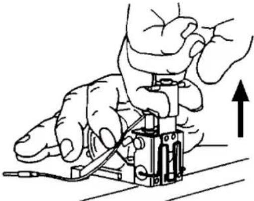  | |
| 5 Place the stapler head back into the Océ BLM200. The driver post arm (2) must be placed into the stapler lift bracket (1). | ||
| CautionIf the driver post arm is not correctly positioned into the stapler lift bracket (2) it will cause permanent damage to the stapler head as well as the bracket. Subsequently, also future correctly mounted stapler heads will be damaged. | ||
| 6 Press on the lower front edge of the stapler head to align the hole (3) in the stapler bracket with the hole in the stapler head. Insert the locking pin (4) so that it engages the stapler head and the metal sides of the stapler assembly. | ||
| 7 Lock | the pin (4) by rotating it towards the in-feed side. Check that the stapler head is correctly mounted by pushing the stapler head towards the infeed area. If it is still loose, it is not correctly mounted. Tighten thumb-screws, Changing Stapler and Clincher position. | 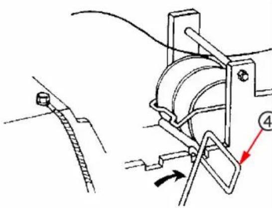 |
| 8 Insert | the staple detection lead into its socket. | |
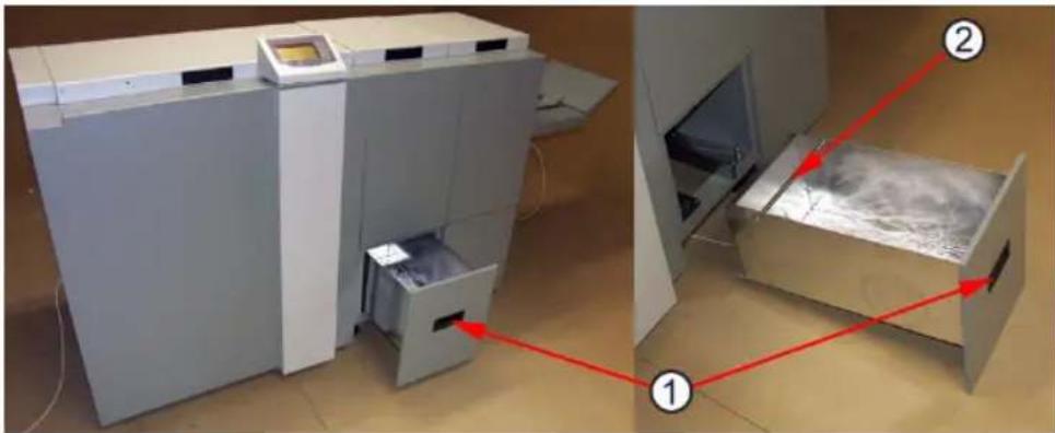
Empty the trim bin
Illustration
natural_image
Two industrial machines in a lab setting, one open and one closed with red arrows pointing to internal components (no visible text or symbols)Procedure
| Step Action | |
| 1 Remove the trim bin by pulling handle (1) | |
| 2 then lift it out by grasping the rod (2) and handle (1). |
Chapter 3 Make booklets

text_image
océChange settings
General procedure
Introduction
Changing settings can be performed in two ways. Temporary, which means that the changes will remain until a new job is loaded or permanent, which means that the changes will be stored as a job. This job can later be recalled.
Procedure for temporary changes:
From the Main screen, select the option you wish to change and press the [Enter] button. Confirm changes by pressing the [Enter] button in the next screen.
Procedure for permanent changes:
Same procedure as for temporary changes. But, in addition, from the Main screen, press the [Jobs] button to reach the Jobs screen. Select Save if you want to incorporate the change in the current job or Save as... if you want to store the changed job as a new job.

Note: Choose either of the above mentioned procedures when changing size, stapling, trimming or Square folding as follows.
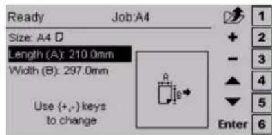
Set the paper size
Select standard paper sizes
Procedure
| Description | |
 | From the Main screen, select Size and press the [Enter] button. |
 | Current Size is highlighted. Press [+] or [-] to scroll within the preset paper sizes. Press [Enter] to select. |
Custom paper size
Procedure
| Description | |
 | From the Main screen, select Size and press the [Enter] button. |
 | Select Length or Width, whichever you wish to change. Press the [+] or [-] button to correct paper size. The paper size can be changed in increments of 0.1 mm or approx.. 0.01 inches. Press the [Enter] button to confirm. |
Staple and Fold
Select stapling mode
Procedure
| Description | |
 | From the Main screen, select Staple and press the [Enter] button. |
 | With the Staple line highlighted, press [+] or [-] to choose stapling option. Press the [Enter] button. |
Adjust staple and fold alignment
Procedure
| Description | |
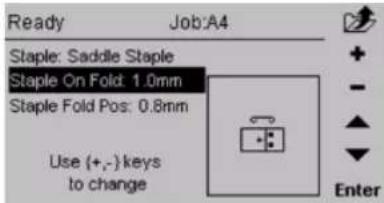 | If the booklets exiting the system do not have the sta- ples centred on the fold, or if stapling position is de-sired on the top or bottom of the spine, that can be adjusted from the control panel. With Staple On Fold highlighted, press [+] or [-] to move staple position-ing on the spine. Press the [Enter] button. |
| Note: The adjustment can also be done during booklet making. | |
 | If the booklet fold line is not in the centre of the sheet, or if it is desirable to move the fold line to match the print, that can be adjusted from the control panel. Contrary to the above situation, this adjust- ment moves both the staple and fold together. With Staple Fold Pos highlighted, press [+] or [-] to move the staple and fold line position. Press the [Enter] button. |

Note: The stapler heads are fixed in one position and are not, therefore, user adjustable
Adjust fold quality
Introduction
If the adjustments from the control panel result in inconsistencies or inaccuracies it could be due to paper quality and/or set size. For those cases it is possible to change the ball configuration in the ball cages in the pre-fold transport. The purpose is to apply adequate pressure on the set to ensure proper alignment against the fold stop before the set is folded. The default configuration for Océ BLM200 is with glass balls closest to the outfeed and plastic balls closest to the infeed. Additional replacement steel, glass and plastic balls are located in the tool box above the fold section. See Ball Configuration Guidelines table.

Note: The table below is meant purely to be a guide. Other configurations might work better depending on the characteristics of the paper quality in conjunction with the set size.
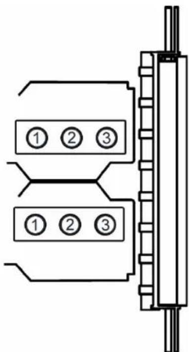
text_image
① ② ③ ① ② ③Procedure
| Ball Configuration Guidelines 1 2 3 | |||
| Single large sheets, in fold only mode, with low paper weight/stiffness | - | - | P |
| Small quantity of sheets, with low paper weight/stiffness | Plastic - Plastic | ||
1
| Ball Configuration Guidelines 1 2 3 | |||
| Default configuration Plastic - Glass | |||
| Large quantity of sheets Glass - Glass | |||
| Large quantity of sheets, with higher paper weight/stiffness | Glass - Steel | ||
| If markings occur on the centre fold when running larger quantities of sheets | Plastic Plastic Glass |
Procedure
| Description | |
 | In extreme circumstances, when the cover sheet tends to be torn from the rest of the set, this can be rectified by adjusting the Fold Adjust Levers located above the pre-fold transport. There are eight positions for each lever. The topmost notch (1) is the default position. Move the lever notch by notch until performance is satisfactory. |
Set up narrow width paper sizes
If setting up narrow width paper sizes such as A5, 5.5x8.5" or CD-size, the side guide extensions (2) must be removed.
| Step Action Description | ||
| 1 Remove thumb screws (1), one on each side guide. | 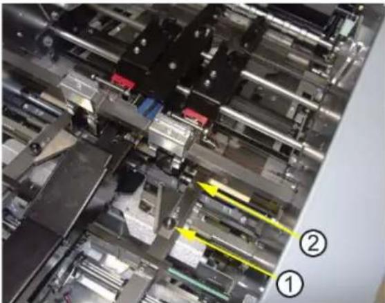 | |
| 2 Remove side guide extension (2), one on each side guide. | ||
 Note: Make sure to re-install the side guide extensions when this job is finished. Otherwise paper jams might occur. Note: Make sure to re-install the side guide extensions when this job is finished. Otherwise paper jams might occur. | ||
Trim
Select trim on or off
Procedure
| Description | |
 | From the Main screen, select Front Trim and press the [Enter] button. |
 | Press the [+] or [-] button to change Front Trim on or off. Press the [Enter] button |
Adjust the cutting margin
Procedure
| Description | |
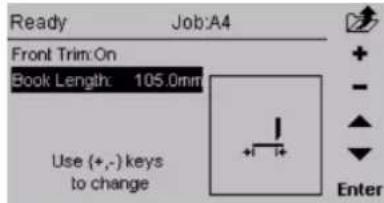 | Select Book Length and press the [Enter] button. Press the [+] or [-] buttons to make fine adjustments. The measurement displayed is the width of the finished, trimmed booklet. Press the [Enter] button to confirm. |
SquareFold module
General
Introduction
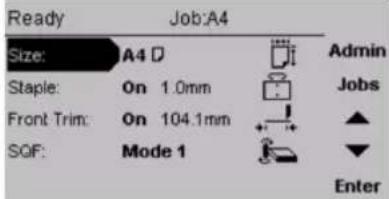
The SquareFold module has five different settings. It can be set to [Auto], [Mode 1], [Mode 2], [Mode 3] or [Off].
In [Auto] mode, the booklet maker detects how many sheets there are in the booklet, and automatically set the SquareFold module to the correct mode.

Note: When the SquareFold module is set to [Auto] and the booklet has less than approximately 6 sheets/booklet, the SquareFold module will bypass the Square folding action, transporting the booklet out to the Belt stacker.
Use the manual modes to override the auto function. There are four different manual modes to select from.
| Mode | Description |
| 1 | Approximately 6 to 11 sheets. Decreased amount of square forming. |
| 2 | Approximately 12 to 16 sheets. Medium amount of square forming. |
| 3 | Approximately 17 to 25 sheets. Maximum amount of square forming. |
Select [Off] to bypass the SquareFold module
Select the SquareFold module mode
Procedure
| Description | |
 | From the Main screen, scroll down to SQF and press the [Enter] button. |
 | Select [Auto], [Mode 1], [Mode 2], [Mode 3] or [Off] with the [arrow] button and press the [Enter] button. |
Rotator module for Océ VarioPrint 2090, 2100, 2110, 3070, 3090, 3110 and 6250 printers.
General
Description
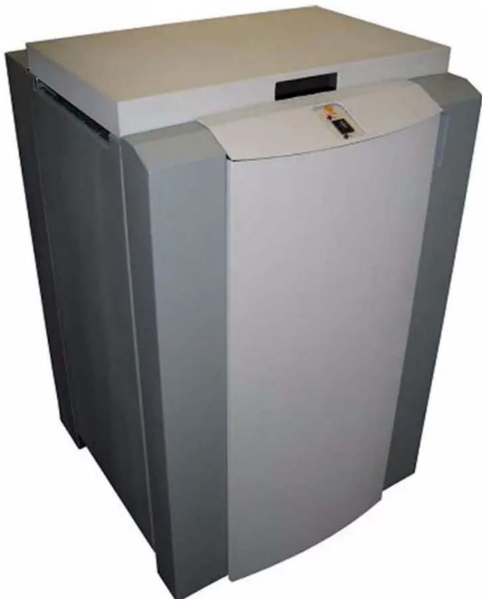
natural_image
Exterior view of a modern white industrial refrigerator with a control panel (no visible text or symbols)To get the highest functionality for multi format finishers, a rotator module is available that is compatible with the Océ VarioPrint 2090, 2100, 2110, 3070, 3090, 3110 and 6250 printers.
This rotator is specifically designed in order to improve processing speed in situations where the receiving finisher needs to be fed short edge first. (e.g. when making A5 booklets)
It is possible to readjust the rotator module automatically from Bypass to Rotation mode and vice versa: A4 and Letter are used with the Rotation mode enabled while A3 and Ledger run in Bypass mode, allowing finishers that can receive mixed jobs to run at maximum speed with a minimum of operator intervention.
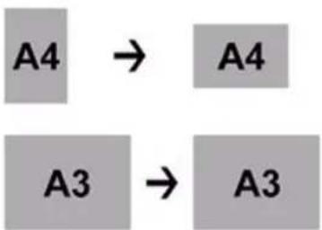
flowchart
graph LR
    A4 --> A4
    A3 --> A3
The rotator module can be placed directly between a printer and a booklet maker, or behind an Océ HCS or an HVS6000 high capacity stackers if present.

natural_image
Industrial machine with control panel and storage unit (no visible text or symbols)
Note: When the rotator is used in a booklet making configuration, the maximum paper width is 305mm.
Installation
The rotator module has to be installed by qualified technicians, as described in this Manual.
Basic information
Getting to know the rotator module
The rotator module can be quickly and easily connected to an Océ printer.
See the picture below to get familiar with the main components of the rotator module.

text_image
Left Right Rear Front ① ② ③ ④ ⑤| Description Description | |||
| 1 Castors 4 Storage compartment door | |||
| 2 Control panel 5 On/off switch (inside) | |||
| 3 | T o p c | o | v e r |
Control panel

text_image
① Not Ready ② A B ③ ④| Description Description | ||||
| 1 "Not | ready" indicator 4 Bypass mode | indicator | light | |
| 2 Rotator mode indicator light A Mode | button "Up" |  | ||
| 3 Mode | control / On- Offline button■ Auto mode■ Bypass mode■ Rotation mode | B Mode | button “Down” |  |
On/off switch (inside)

natural_image
Close-up of a mechanical device with a red circle highlighting a component, alongside a close-up of its internal components (no visible text or symbols)Basic operation
Prepare the rotator module
Introduction
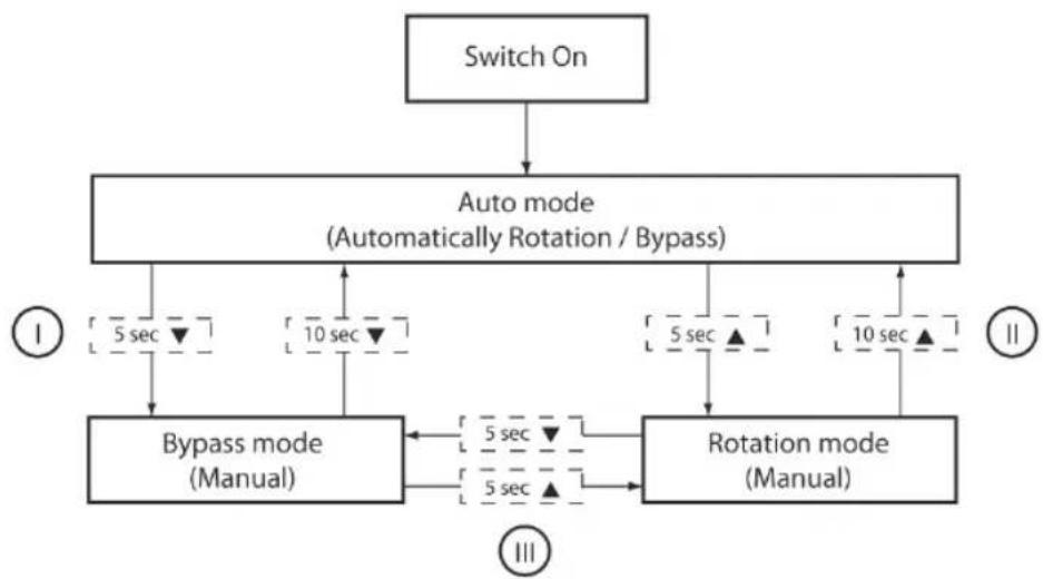
This section explains how to use the rotator module during normal operation. After switching on the rotator module it will operate in the Auto mode (Automatically Rotation / Bypass)
Prepare the printer / copier and finishing devices as described in their respective manuals. After switching on the rotator module the printer / copier will decide if the rotator module runs automatically in Rotation or Bypass mode.
Illustration
flowchart
graph TD
    A["Switch On"] --> B["Auto mode (Automatically Rotation / Bypass)"]
    B --> C1["5 sec ▼"]
    B --> C2["10 sec ▼"]
    B --> C3["5 sec ▲"]
    B --> C4["10 sec ▲"]
    C1 --> D1["Bypass mode (Manual)"]
    C2 --> D1
    C3 --> D2["Rotation mode (Manual)"]
    C4 --> D2
    D1 <--> D3["5 sec ▼"]
    D2 <--> D3
    D3 <--> D4["5 sec ▲"]
    D4 --> E1["①"]
    D3 --> E2["②"]
    D4 --> E3["③"]
Select operation mode:
| 1 | Auto mode |  | Bypass mode |
Press the Mode control button 3B  for 5 seconds to select the Bypass mode.(The lights (2 & 4) will blink and stop after 5 seconds, then let go of the button) for 5 seconds to select the Bypass mode.(The lights (2 & 4) will blink and stop after 5 seconds, then let go of the button) | |||
| Bypass mode |  | Auto mode | |
Press the Mode control button 3B  for 10 seconds to select the Auto mode.(The lights (2 & 4) will blink after 10 seconds, then let go of the button) for 10 seconds to select the Auto mode.(The lights (2 & 4) will blink after 10 seconds, then let go of the button) | |||
| 2 Auto mode | → | Rotation mode | |
| Press the Mode control button 3A ▲ for 5 seconds to select the Rotation mode.(The lights (2 & 4) will blink and stop after 5 seconds, then let go of the button) | |||
| Rotation mode | → | Auto mode | |
| Press the Mode control button 3A ▲ for 10 seconds to select the Auto mode.(The lights (2 & 4) will blink after 10 seconds, then let go of the button) | |||
| 3 Bypass mode | → | Rotation mode | |
| Press the Mode control button 3A ▲ for 5 seconds to select the Rotation mode.(Light 4 will switch over from Bypass mode to Rotation mode) | |||
| Rotation mode | → | Bypass mode | |
| Press the Mode control button 3B ▼ for 5 seconds to select the Bypass mode.(Light 2 will switch over from Rotation mode to Bypass mode) | |||
The 5 and 10 second delays prevent accidental mode changes. After changing the operation mode, always press the Mode button "Up" to confirm "ready".
The rotator module is now ready for use. Make sure to set up other finishing devices according to their respective manuals.
To check the Operation mode of the rotator module, press the Mode control button 3A shortly. If the lights are flashing then the rotator module will operate in Auto mode. If the lights do not flash then the rotator module will operate in Manual mode.
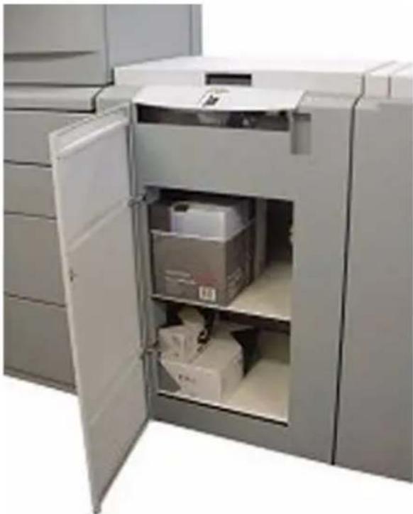
Storage compartment
Procedure
- Open the door to access the storage compartment.

natural_image
Close-up of a hand pressing down on a white electronic device with a small chip (no visible text or symbols)- Store supplies and spare parts for the printing system and finishing devices to make sure they are within reach
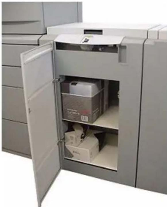
natural_image
Interior view of a large open storage cabinet with visible cardboard boxes and metal casing (no text or symbols)See chapter 1, 'Safety', for more information on how to use the storage compartment.
Maintenance
Cleaning
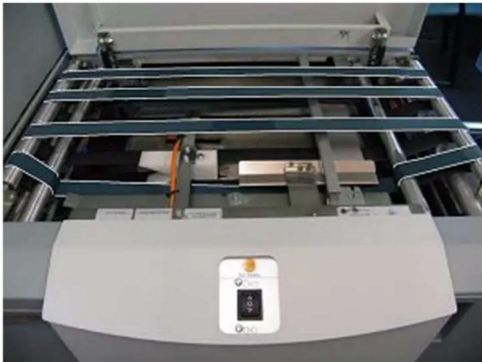
Introduction
To keep your supplies clean, dust the inside of the rotator module's storage compartment at least once every month and clean it with a moist cloth (Marked area):
Illustration

natural_image
Exterior view of a white industrial machine with green internal compartments and open door (no text or symbols visible)When finished sets have a slight mark or dust on them, clean the rotator module's belts with a moist cloth. The marked area shows only the visible part of the belts, so turn the belts and make sure to clean all surfaces carefully.
natural_image
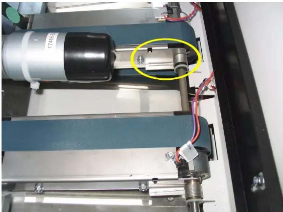
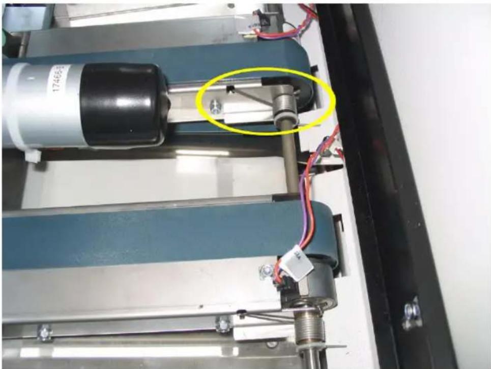
Interior view of a laboratory instrument with metal grating and control panel (no visible text or symbols)Sheets / sets are rotated by clamping one corner. If a clearly visible dot appears on the paper, clean both sides of the clamping mechanism.
natural_image
Industrial machine with blue conveyor belts and metal components, highlighted by a red circle (no visible text or symbols)Problem solving
"Not Ready" Status indicator
The "Not Ready" indicator blinks if an error has occurred in the rotator module, or in one of the finishers placed behind the rotator module.
Generally, "Not Ready" messages are displayed on all finishers before the finisher having the error. This means that when an error occurs, it must be solved on the finisher last in line first. If no additional errors are detected in the rotator module, and all errors in finishers behind the rotator module are solved, the rotator module will automatically assume the "Ready" position, and will communicate correspondingly to the printer or other finishers before the rotator module.
In short, this means that errors only need to be solved in the module actually having the error. All other modules will automatically detect when an error in another module has been cleared.
Clear paper jams
Procedure
- Open the top cover

natural_image
Person using a printer to press or install a paper airplane (no visible text or symbols)- Pull the upper transporter belts towards the paper infeed (see arrow). The jammed paper will move towards the paper output.

natural_image
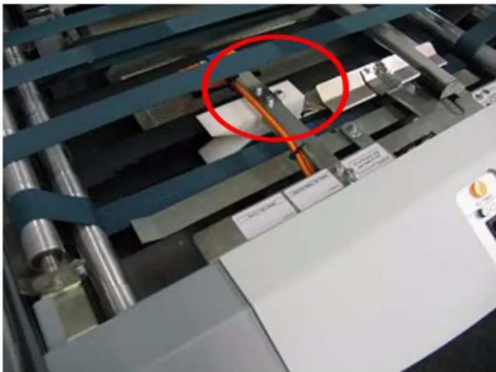
Interior view of a printer or scanner with blue frame structure and orange connectors (no visible text or symbols)If paper cannot be moved towards the paper output, try to pull it out carefully between the belts.
After clearing a paper jam always check if the belts, including the drive belt (to the belt motor) are in place.
- Close the top cover
Online/Offline
Introduction
The booklet maker can be operated in two modes. Online mode, when used together with the printer, or offline mode, when used for hand feeding.
Offline Mode
- Make sure booklet maker is in stand-by mode, i.e. ensure that an online print job is not in progress.
- Make necessary settings according to "Changing settings" earlier in this section.
- The booklet maker is now in stand-by mode and will start automatically when a set is manually fed into the booklet maker.
- Sets can be fed one at a time into the opening at the left-hand end of the booklet maker.
Online Mode
- Make necessary settings according to "Changing settings" earlier in this section.
- The booklet maker is now in stand-by and will start automatically when a set is fed from the printer.
Chapter 4 System administration
The Admin screen
Language
Before you begin
From the main screen, press the [Admin] button to get to the admin screen. Here you will find additional features and settings.
Procedure
| Description | |
 | From this screen you can change the language in the user interface. Select Language and press the [Enter] button. |
 | Select desired language with the [arrow] buttons and press the [Enter] button. |
Size standard
Before you begin
From the Main screen, press the [Admin] button to get to the admin screen. Here you will find additional features and settings.
Procedure
| Description | |
 | From this screen you can change the paper size standard. By changing the paper size standard the preset paper sizes are altered to best fit your regional standard. Also, the units will change between millimeters and inches accordingly. Select Size Standard and press the [Enter] button. |
 | Select the desired standard and then press the [Enter] button. |
Service
Before you begin
From the main screen, press the [Admin] button to get to the admin screen. Here you will find additional features and settings.
Procedure
| Description | |
 | This screen to access service is for authorised service personnel only and is password protected. |
Chapter 5 Job control

text_image
océStore a job
Introduction
The booklet maker has a maximum storage capacity of 10 different jobs.
Procedure
| Action | |
 | Change all settings according to section 2 for a particular job. Now the changes are just temporary. You can run the system with these changes but as soon as you change something again the previous settings will be lost. To store the settings, press [Jobs] from the Main screen. |
 | Now you have three choices:■Save■Save as...■RenameChoosing Save will overwrite the current Job. The Current Job name is displayed on top of the screen.Choosing Save as... gives you the option to save it as a new job or overwriting another job.Choosing Rename will overwrite the Current Job (if changes were made). This is the same as the Save option, but now you have the possibility to enter or change the name for the current job. |
 | This screen is displayed if Rename is Entered from the Jobs screen.Press [+] or [-] to change highlighted character. Press [Blank] for no character. Move the cursor by pressing the [Arrow]. Press [Enter] when done. |
Recall a job
Introduction
The booklet maker has a maximum storage capacity of 10 different jobs.
Procedure
| Action | |
 | To recall a stored job press the [Jobs] button from the main screen.. |
 | Then press the [Jobs] button from the jobs screen. |
 | Select one of the previously stored jobs from the list. Press the [Enter] button to recall the job. This job is now uploaded and becomes the current job. |
Chapter 6 Clear a paper jam

text_image
océGeneral
Introduction
If an error such as a paper jam condition should occur, it is indicated on the booklet maker display. The nature of the fault is generally displayed in clear text at the top. In the centre of the display the diagram shows in which module the error has occurred. At the bottom of the display usually an error code is displayed and a text explaining the error. See examples below.
Procedure
| Description | ||
| Flashing symbol Jams in the | booklet maker are indicated by a square shaped symbol flashing in the display. | |
 | ||
 | ||
Top cover highlighted and  | If one of the top covers is open, the symbol on the screen shows the top cover flashing. | |
| Cover Open Job:A4 | ||
 | ||
| Jam Code: Jam Text | ||
Booklet maker
To clear a paper jam in the infeed or staple area
- Open the top cover.
- Remove jammed sheets.
- Close the top cover.
To clear a jam indicated in the folding area
- Open the top cover.
- Close top cover.
If a jam still remains (1)
- Switch off the Power.
- Switch on the Power.
If a jam still remains (2)
- Switch off the Power.
- If a trimmer is installed, first remove the Trim Bin to get access to the fold stop. This gives you access underneath the trimmer, where you can pull down the fold stop.
- Remove jammed sheets.
- Push the fold stop back into the upper position.
- Replace the Trim Bin, if the Trim Bin was removed.
- Switch on the Power.
Trimmer input area
Introduction
The upper trimmer blade on the trimmer is protected by a knife protection plate that moves away during the cutting stroke. Jams can occur in the input area or the exit area.

Caution: Never put fingers or other parts of the body between the upper and lower trimmer knives.
Illustration

text_image
Technical diagram of a mechanical device with labeled components and directional arrows indicating movement or assembly.Procedure
- Lift up the infeed roller shaft (1).
- Secure under latch (2)
- Remove the jammed sheets in the infeed area.
- After the jammed sheets are removed, lift up the latch (2) and place the infeed roller shaft in the operating position.
Trimmer exit area
Introduction
The upper trimmer blade on the trimmer is protected by a knife protection plate that moves away during the cutting stroke. Jams can occur in the input area or the exit area.

Caution: Never put fingers or other parts of the body between the upper and lower trimmer knives.
Illustration
natural_image
Interior view of a mechanical testing machine with numbered components and wiring (no visible text or symbols)Procedure
-
Lift the exit compression brackets (1).
-
Secure them under the latch (2).
-
Remove the jammed sheets from the exit area.
-
After the jammed sheets are removed, lift up the latch (2) and place the compression brackets in the operating position.
SquareFold Module
Procedure
| Step Action Description | ||
| 1 Open the top cover. |  | |
| 2 Lift up both upper feed belts (1). | ||
 Note: Press the green-la-belled latches (2) to release. Note: Press the green-la-belled latches (2) to release. | ||
| 3 Remove the jams. | ||
| 4 Place the upper feed belts in normal position. | ||
| 5 Close the top cover. | ||
SquareFold Module exit area
Procedure
| Step Action Description | ||
| 1 Open | the top cover (1). |  |
| 2 Lift up the Belt Stacker Cover (2). | ||
| 3 Remove the jam. | ||
| 4 Place | the Belt Stacker Cover in normal position. | |
| 5 Close | the top cover. | |
Chapter 7 Troubleshooting

text_image
océFault codes
General
Introduction
When there is a jam or fault condition in the booklet maker system, a message will be displayed on the booklet maker. (see ‘Booklet maker’ on page 65). Some faults can be rectified by the operator and some faults only by an authorised technician.
Fault codes that generally can be rectified by the operator:
| Location Error code | |
| Booklet maker: BM-2XX to | BM-4XX |
| Trimmer: TR-2XX to TR-5XX | |
| SquareFold module: SQF-2 | XX to SQF-5XX |
| As well as a fault code, a brief description is given on the display. | |

Note: If procedures in this manual do not rectify the problem an authorised technician will be needed.
Booklet maker fault codes
Check Staples
This message will be displayed when a staple cartridge is empty or when stapling could not be performed. Check in the following order:
■ If a staple cartridge is empty, replace according to section 1 Basics.
■ If staple cartridges are OK; remove the set and check that the number of sheets is within specifications.
■ If staple cartridges are OK and the set is within specification, remove and check stapler head according to section 1 Basics.
Booklet quality fault
Booklet Quality
If booklet quality is inconsistent, first make sure the actual paper size is matching the paper size set on the control panel. If that is perfectly correct, (see ‘Adjust fold quality’ on page 33).
If booklet quality is consistently poor such as staples not aligned with the fold or staple and fold line do not match the print, (see 'Adjust staple and fold alignment' on page 32).
If the cover of the booklet tends to be torn from the set, (see ‘Adjust fold quality’ on page 33).
Trimmer fault codes
Trim Bin Full
This message will be displayed when the trim bin is full or when a trim strip is prevented from falling down into the trim bin.
Empty the trim bin and remove loose trim strips from inside the trimmer. (see 'Empty the trim bin' on page 25).
SquareFold module fault codes
Feed Errors
If feed errors occur, the feed belts need to be cleaned or the pressure on the upper feed belts needs to be increased. To clean the feed belts, (see 'SquareFold module' on page 88). To increase the pressure on the upper feed belts follow this procedure.
| Step Action | |
| 1 Open | the top cover. |
| 2 Place | both springs in the upper position. |
| 3 Close | the top cover. |
natural_image
Close-up of a mechanical device with a highlighted cylindrical component and wiring, no visible text or symbols.[79] Spring in normal position
natural_image
Close-up of a mechanical testing apparatus with blue and black components and wiring, no visible text or symbols[80] Spring in upper position
SquareFolding quality
If the booklets are not square folded properly, especially regarding heavier booklets, do the following:
■Perform action according to above.
- Clean the clamps according to Cleaning Square Folding Clamps, (see 'SquareFold module' on page 88).
Chapter 8 General remarks

text_image
océDo's and don'ts
Introduction
■ Always follow all warnings marked on, or supplied with, the equipment.
■ Always exercise care in moving or relocating the equipment.

Caution: - Unplug the power cord from the wall outlet and machine before you move or relocate the equipment.
- Do not remove the covers or guards that are fastened with screws.
- Do not override or bypass electrical or mechanical interlock devices.
- Do not operate the equipment if you notice unusual noises or odours.
Disconnect the power cord from the power source and call your authorised technician to correct the problem.

Attention: This is a Class A product. In a domestic environment this product may cause radio interference in which case the user may be required to take adequate measures.
Rules

Note: The domestic environment is an environment where the use of broadcast radio and television receivers may be expected within a distance of 10 m of the apparatus concerned.
■ Do not put fingers or other parts of the body between the upper and lower trimmer knives.
■ Do not switch off the power while the machine is running. Make sure the machine cycle has ended.
■ Do not open covers while the machine is running.
■ Do not move machine while the machine is running.
■ Do not make arbitrary changes to the machine
Rotator module
- Do not connect power to the Rotator module when it's not mechanically connected to the printer or a finisher that is already connected to the printer.
- Do not operate the Rotator module when it's not mechanically connected to the printer or a finisher that is already connected to the printer.
The storage compartment of the Rotator module is for storage of normal supplies only.
■ Do not store powered electrical devices in the storage compartment.
■ Do not store heat sources, hot materials, flammable or explosive materials in the storage compartment.
■ Do not use the Rotator module in any way as a stand or ladder.
■ Do not store magnets or magnetic devices in the storage compartment.
■ Do not store materials with excessive weight inside the storage compartment.
■ Do not store fluids or gasses or their empty containers inside the storage compartment.
natural_image
Interior view of a large open industrial storage cabinet with internal compartments (no visible text or symbols)Place the machine

Caution: Improper grounding of the equipment can result in electrical shock.
Machine environment
■ Always locate the equipment on a solid support surface with adequate strength for the weight of the machine.
■ Always keep magnets and all devices with strong magnetic fields away from the machine.
If the place of installation is air-conditioned or heated, do not place the machine where it will be:
■ Subjected to sudden temperature changes.
■Directly exposed to cool air from an air-conditioner.
■ Directly exposed to heat from a heater.
Power connection
■ Always connect the equipment to a properly grounded power source. If in doubt, have the power source checked by a qualified electrician.
■ Improper grounding of the equipment can result in electrical shock.
■ Never connect the machine to a power source that lacks a ground connection terminal.
Access to machine
Place the machine near the power source, providing clearance as shown.
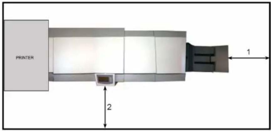
text_image
PRINTER 1 2| Number Description |
| 1 Right: more than 400 mm / 15 3/4” |
| 2 Front: more than 555 mm / 21 7/8” |
Maintain the machine
Booklet maker

Attention: Never attempt any maintenance function that is not specifically described in this documentation.
Lubricate staplers and clinchers
text_image
Technical diagram of a mechanical assembly with numbered components and red directional arrows indicating motion or force directions.| PART FREQUENCY | PART LOCATION | |
| (1) Drive post Every 20,000 booklets Staple cartridge (grease) | ||
| (2) Stapler drive bar Every 20,000 booklets Above the stapler head (grease) | ||
| (3) Stapler lift bracket Every 20,000 booklets Above the stapler head (grease) | ||
| (4) Staple driver Every 20,000 booklets Staple driver (thin oil) | ||
| (5) Clincher Every 20,000 booklets Beneath the stapler head as-sembly (thin oil) | ||
Trimmer
Introduction
If a squeeking notice is heard from the trimmer, use the wax cylinder located in the tool box on the Booklet Maker to lubricate the upper Trimmer knife.
Lubricating trimmer knife
| Step Action Description | ||
| 1 Switch of the power. |  | |
| 2 Open | the Trimmer top cover and lift the exit compression brackets and secure them under the latch (see ‘Trimmer exit area’ on page 68) | |
| 3 Use | the wax cylinder (1) found in the Booklet maker tool box and rub it along the side of the upper trimmer knife (2). Lift the five plungers (3) one by one when needed in order to reach the trimmer knife. | |
| 4 After | lubricating the trimmer knife, lift up the latch and place the compression brackets in the operating position (see ‘Trimmer exit area’ on page 68) and close the Trimmer top cover. Rub wax on this (4) surface only. | |
| 5 Switch | on the power. | |
SquareFold module
Introduction
The feed belts need to be cleaned regularly when in use, and if the unit has not been used for a period of time. How often this should be done, depends on the paper type and print quality.
An increasing number of jams is one indication of the need to clean the feed belts.
Clean the feed belts with water and a lint free cloth.

Attention: Never attempt any maintenance function that is not specifically described in this documentation.
Clean the feed belts
| Step Action Description | |
| 1 Open the top cover. |  |
| 2 Clean the upper feed belts (1).The upper feed belts can easily be rotated in either direction. | |
| 3 Lift up the upper feed belts to access the lower feed belts. | |
| 4 Clean the lower feed belts (2).Rotate the lower feed belts towards the outfeed side for complete cleaning. | |
| 5 Place the upper feed belts in normal position. | |
| 6 Close the top cover. | [86] Upper feed belts in normal position |
 | |
| [87] Upper feed belts raised |
Clean Square Folding Clamps
Clean off any silicon residue from upper and lower clamps (1), which is the area clamping/contacting the booklet. Pay special attention to the right angled corners of the clamp profiles.

natural_image
Interior view of a mechanical device with labeled component (1), showing internal components and mounting holes (no text or symbols beyond label)Chapter 9 Specifications

text_image
océMachine Specifications
Booklet maker Océ BLM200
| Basic Specifications | ||
| Specifications Remarks | ||
| Speed (Online usage) | Maintains printer speed Production (in number of booklets per hour) depends on number of sheets per booklet. | |
| Maximum Speed 3000 booklets / hour (A4/8 1/2 x 11" sheets) | ||
| Paper Size (Minimum) Online | Width 208 mm / 8 3/16"Length 248 mm / 9 3/4" | Except Océ VarioPrint6160/6200/6250Width 203 mm / 8"; Length 248 mm / 9 3/4" |
| Except Océ CPS800/900Width 203 mm / 8"; Length 267 mm / 10 1/2" | ||
| Paper Size (Maximum) Online | Width 305 mm / 12"Length 457 mm / 18" | Except Océ VarioPrint6160/6200/6250Width 305 mm / 12"; Length 470 mm / 18 1/2" |
| Except Océ CPS800Width 210 mm / 8 1/4"; Length 297 mm / 11 3/4" | ||
| Except Océ CPS900Width 305 mm / 12"; Length 457 mm / 18" | ||
| Paper Size (Minimum) Hand-feeding only | Width 140 mm / 5 1/2"Length 248 mm / 9 3/4" | |
| Paper Size (Maximum) Hand-feeding only | Width 305 mm / 12"Length 470 mm / 18 1/2" | |
| Paper Weight 60 gsm/16 lb. Bond - 300gsm/172 lb. Index / 115 lb. | ||
| Input / Output Sheets | 1 – 25 Sheets (80 gsm / 20 lb. Bond, or equivalent) | Stapled |
| Input / Output Sheets | 1 Sheet Folding only | |
| Hand feeding Possible | ||
| Weight 150 kg / 331 lb Including Conveyor Stack-er | ||
| Dimensions (L x H x D) | 1540 x 1135 x 680 mm / 60” x 45” x 27” | Including Conveyor Stack-er |
| Power Source 100 / VAC50-60Hz | +/- 10% | |
| Power Consump-tion | 800 W or less Continuous Operation for Océ BLM200+ Trimmer + SquareFold module | |
| The machine design and specification are subject to change without notice. | ||
Trimmer BLT6289 / BLT6789 (option)
| Specifications Remarks | ||
| Speed Maintains printer speed | ||
| Minimum trimming | *4 mm / 0.16 in | |
| Maximum trimming | 16 mm / 0.63” | |
| Paper Weight (Minimum) | Same as Océ BLM200 | |
| Paper Weight (Maximum) | Same as Océ BLM200 | |
| Input / Output Sheets | Same as Océ BLM200 | |
| Hand feeding Possible (Together with Booklet | Maker) | |
| Weight 90 kg / 198 lb | ||
| Dimensions (L x H x D) | 360 x 1135 x 680 mm / 14” x 45” x 27” | |
| Power Source From | Océ BLM200 | |
| The machine design and specification are subject to change without notice. | ||
* Maximum width of the finished, trimmed booklet is 220 mm (8 5/8"). When trimming SRA3 (450 mm) booklets, the minimum trim is 5 mm. When trimming 18" (457 mm) booklets, the minimum trim is 9 mm.
SquareFold module SFM6204 / SFM6704 (option)
| Specifications Remarks | ||
| Speed Maintains printer speed | ||
| Paper Weight (Minimum) | Same as Océ BLM200 | |
| Paper Weight (Maximum) | Same as Océ BLM200 | |
| Input / Output Sheets | Same as Océ BLM200 | |
| Hand feeding Possible (Together with Booklet | Maker & Trimmer) | |
| Weight 60 kg / 132 lb | ||
| Dimensions (L x H x D) | 360 x 1135 x 680 mm / 14” x 45” x 27” | |
| Power Source From | Océ BLM200 | |
| The machine design and specification are subject to change without notice. | ||
Rotator RTM6240 (option)
| Specifications Remarks | ||
| Speed Maintains printer speed | ||
| Paper Size (Mini-mum) | Same as Océ BLM200 | |
| Paper Size (Maxi-mum) | Same as Océ BLM200 | |
| Paper Weight (Minimum) | Same as Océ BLM200 | |
| Paper Weight (Maximum) | Same as Océ BLM200 | |
| Input / Output Sheets | Same as Océ BLM200 | |
| Hand feeding Not possible | ||
| Rotation enabled A4 or Letter sizes only All other sizes are bypassed | ||
| Weight 100 kg / 220 lb | ||
| Dimensions (L x H x D) | 680 x 1135 x 700mm / 27" x 54" x 28" | |
| Power Source 220 - 240 VAC 50Hz +/- 10% | ||
| or 100 - 127 VAC 60Hz + 6% / - 10%For USA (and similar vol-t-age countries) only | ||
| Power Consump-tion | 460W or less | |
| or 360W or less | For USA (and similar vol-t-age countries) only | |
| The machine design and specification are subject to change without notice. | ||
Index
A
Adjust fold quality 33
Admin
Language 56
Service 58
Size standard 57
B
booklet maker
Offline mode 53
Online mode 53
Booklet Maker fault codes 75
Booklet maker parts 10
Booklet quality fault 76
Buttons 9
C
Clean square folding clamps 90
Clean the feed belts 89
Clear a paper jam
Folding area 65
General 64
Infeed or staple area 65
SquareFold Module 70
SquareFold Module exit area 71
Trimmer exit area 68
Trimmer input area 66
Control panel 9,15
Custom paper size 30
Cutting margin 37
D
Do's and don'ts 82
E
Empty trim bin 25
F
Fault codes 74
|
Installation 42
L
Lubricating trimmer knife 87
M
Maintenance
Booklet maker 86
SquareFold module 88
N
Narrow width paper sizes 35
P
Permanent changes 28
Place the machine 84
R
Recall a job 61
Remove staples 19
Replace the stapler head 22
Replace the staples 21
Rotator module 40
"Not Ready" Status indicator ..... 51
Automatically rotation/bypass 46
Basic information 43
Bypass mode 46
Cleaning 49
Clear paper jams 52
Rotation mode 46
Storage compartment 48
S
Select standard paper sizes 29
Select stapling mode 31
Specifications
Booklet maker 92
Rotator RTM6240 (option) .....96
SquareFold module 95
Trimmer 94
SquareFold module fault codes .....78
SquareFold module mode 38
Select 39
SquareFold module parts 14
SquareFolding quality 79
Staple and Fold Alignment 32
Staple cartridge 19
Stapler head Replace ....22
Stapling mode 31
Store a job 60
T
Temporary changes 28
Trim on or off 36
Trimmer fault codes 77
Trimmer parts 12
Turn on/off 18