
GDK5792 - Range hood GRUNDIG - Free user manual and instructions
Find the device manual for free GDK5792 GRUNDIG in PDF.


| Product type | Range hood |
| Brand | Grundig |
| Model | GDK5792 |
| Installation type | Built-in / Under cabinet |
| Width | 90 cm |
| Depth | 50 cm |
| Height (min-max) | 60 - 110 cm |
| Weight | Approx. 15 kg |
| Power supply | 220-240 V, 50 Hz |
| Maximum power consumption | 250 W |
| Motor power | 200 W |
| Number of motors | 1 |
| Extraction capacity (max) | 650 m³/h |
| Number of speeds | 3 + intensive |
| Noise level (max speed) | 65 dB(A) |
| Lighting | 2 x LED (2.5 W each) |
| Filter type | Aluminum grease filter, washable |
| Carbon filter | Optional, for recirculation mode |
| Duct diameter | 150 mm |
| Control type | Electronic push buttons |
| Energy class | A+ |
| Annual energy consumption | 30 kWh/year |
Frequently Asked Questions - GDK5792 GRUNDIG
User questions about GDK5792 GRUNDIG
0 question about this device. Answer the ones you know or ask your own.
Ask a new question about this device
Download the instructions for your Range hood in PDF format for free! Find your manual GDK5792 - GRUNDIG and take your electronic device back in hand. On this page are published all the documents necessary for the use of your device. GDK5792 by GRUNDIG.
USER MANUAL GDK5792 GRUNDIG
natural_image
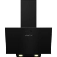
Exterior view of a stainless steel kitchen range hood (no text or symbols visible)
natural_image
Abstract grayscale curved shape on white background, no text or symbols presentPlease read this user manual first!
Dear Customer,
Thank you for purchasing this Grundig product. We hope that you get the best results form your product which has been manufactured with high quality and starte-of-the-art technology.
Therefore, please read this entire user manual and all other accompanying documents carefully before using the product and keep it as a reference for future use. If you handover the product to someone else, give the user manual as well. Follow all warnings and information in the user manual.
Remember that this user manual is also applicable for several other models. Differences between models will be identified in the manual.
Please visit the "Support" section on the Grundig website www.grundig.co.uk.to register your 5 year warranty.
Grundig Helpline
0845 603 1234
0345 603 1234
TABLE OF CONTENTS
1 Safety and set-up 6-7
2 At a glance 8
Control, parts and accessories ..... 8
3 Operation 9-12
Connection of motor unit/hood ..... 9
Wall drilling and bracket fixing ..... 10
Mounting the hood body.....10
Connections ducted version
air exhaust system 11
Recirculation version air outlet ..... 11
Electrical connection 11
Fitting the chimney 12
Upper chimney....12
Grease filters 14
Cleaning metal self-supporting
grease filters....14
Activated charcoal filter
(Recirculation version) 14
Replacing the activated
charcoal filter 14
Light unit 14
4 Information 15
Technical data 15
Environmental note.... 15
5 Guarantee 16
6 Service 17
The Instructions for Use apply to several versions of this appliance. Accordingly, you may find descriptions of individual features that do not apply to your specific appliance.
Installation
■ The manufacturer will not be held liable for any damages resulting from incorrect or improper installation.
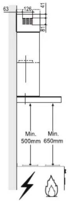
■ The minimum safety distance between the cooker top and the extractor hood is 650 mm (some models can be installed at a lower height, please refer to the paragraphs on working dimensions and installation).

- Check that the mains voltage corresponds to that indicated on the rating plate fixed to the inside of the hood.
■ For Class I appliances, check that the domestic power supply guarantees adequate earthing. Connect the extractor to the exhaust flue through a pipe of minimum diameter 120 mm. The route of the flue must be as short as possible.
■ Do not connect the extractor hood to exhaust ducts carrying combustion fumes (boilers, fireplaces, etc.).
If the extractor is used in conjunction with non-electrical appliances (e.g. gas burning appliances), a sufficient degree of aeration must be guaranteed in the room in order to prevent the backflow of exhaust gas. The kitchen must have an opening communicating directly with the open air in order to guarantee the entry of clean air.
Use
■ The extractor hood has been designed exclusively for domestic use to eliminate kitchen smells.
■ Never use the hood for purposes other than for which it has been designed.
■ Never leave high naked flames under the hood when it is in operation.
■ Adjust the flame intensity to direct it onto the bottom of the pan only, making sure that it does not engulf the sides.
■ Deep fat fryers must be continuously monitored during use: overheated oil can burst into flames.
■ Do not flambè under the range hood; risk of fire.
■ This appliance can be used by children aged from 8 years and above and persons with reduced physical, sensory or mental capabilities or lack of experience and knowledge if they have been given supervision or instruction concerning use of the appliance in a safe way and understand the hazards involved. Children shall not play with the appliance. Cleaning and user maintenance shall not be made by children without supervision.
■ Children should be supervised to ensure that they do not play with the appliance.
Maintenance
■ Switch off the appliance from the mains supply before carrying out any maintenance work.
■ Clean and/or replace the Filters after the specified time period (Fire hazard).
■ Clean the hood using a damp cloth and a neutral liquid detergent.

natural_image
Illustration of a cooking setup with a pot and steam rising, crossed by a green diagonal line (no text or symbols)Control, parts and accessories
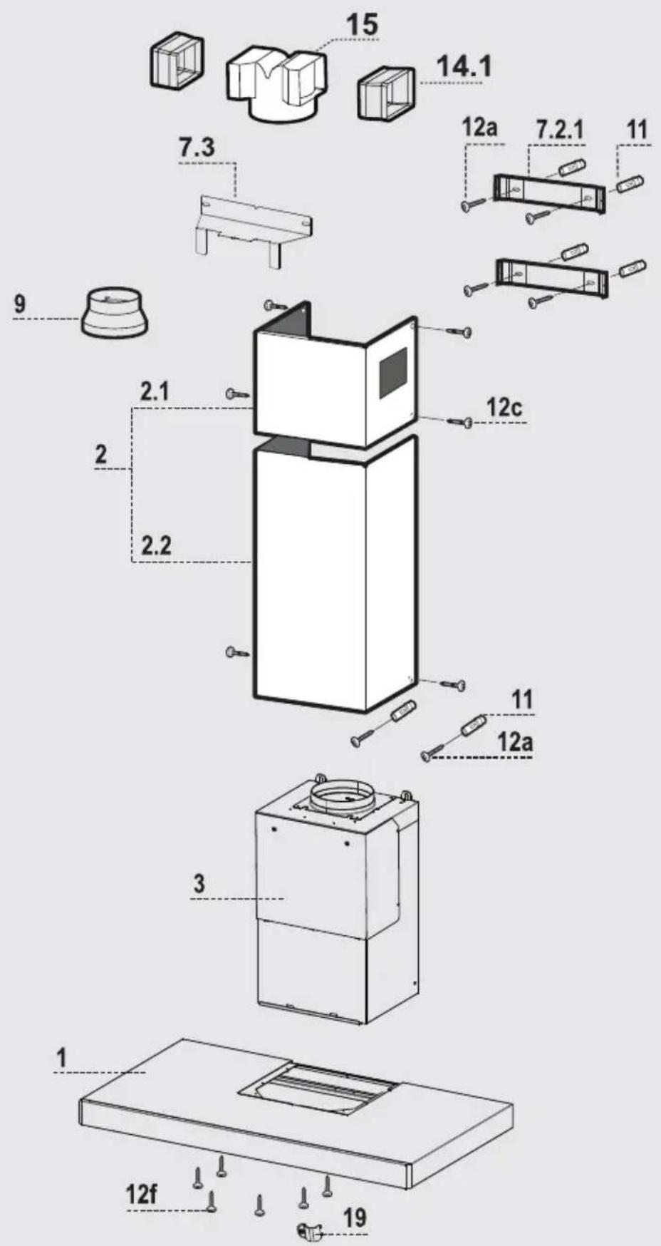
See the figure on page 3.
Ref. Q.ty Product Components
1 1 Hood Canopy complete with: Controls, Light, Filters
2 1 Telescopic chimney, made up of:
2.1 1 Upper chimney
2.2 1 Lower chimney
3 1 Motor unit
9 1 Reduction Flange ∅ 150-120 mm
14.1 2 Air Outlet Connection Extension
15 1 Air Outlet Connection
Ref. Q.ty Installation Components
7.2.1 2 Upper chimney fixing brackets
7.3 1 Air Outlet Connection Support
11 6 Plugs
12a 6 Screws 4.2 x 44.4
12c 6 Screws 2.9 x 9.5
12f 6 Screws 3.5 x 9.5
| GDK 5792 XB | ||
| Type | Wall | Island |
| Depth | 460 mm | |
| Width | 898 mm | |
| Min Height | 730-1060 mm | |
| Supply voltage | 220-240 Volt~ 50 Hz | |
| Control | 4 positions | |
| Suction power 2 | 70-530-645-860 m ^3 /h | |
| Motor power | 270 W | |
| Lamp power | 2x1/4x1W | |
| Total power | 272 W | |
| Air outlet pipe diameter | 120-150 mm | |
| Net weight | 13,3 kg | |
| Gross weight | 17,5 kg | |
| Color | Inox | |
Q.ty Documentation
1 Instruction Manual

Connection Of Motor Unit/Hood
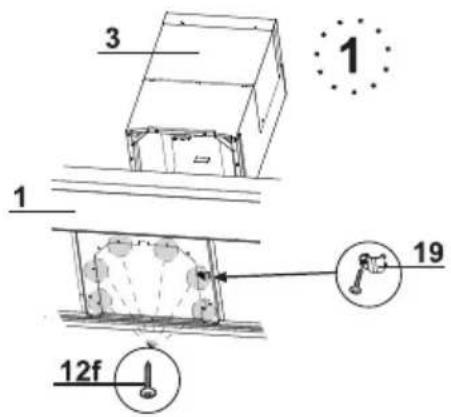
■ Remove the Grease filters from the Hood Canopy 1.
■ Remove any Activated charcoal filters from the Motor unit 3.
■ From inside the Hood canopy, screw the Motor unit 3 to the Hood canopy 1 using 6 Screws 12f provided.
■ Warning: Cable raceway 19 must be screwed into place using one of the Screws 12f to fix it in the position shown in the figure, locking the Hood wiring in place.
■ Warning: Make sure that the Power Cable is not connected, then, if there is one, remove the safety cover over the Connectors in Motor Unit 3 Wiring Box.
■ Make the electrical connections between the Motor Unit 3 and the Hood Canopy 1, connecting the Controls connector and the Lighting connector.
Warning: Make sure that the Connectors are properly inserted into the housing.
Warning: There will be a specific Connector according to the type of controls.
For the Recirculation Version, fit the Activated Charcoal Odour Filter, if there is one.
■ Replace the metal grease filters.

natural_image
Technical line drawing of a mechanical assembly with mounting holes and a numbered circle (no text or symbols)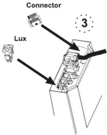
Wall drilling and bracket fixing

Draw the following on the Wall:
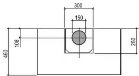
■ a Vertical line up to the ceiling or top surface, at the centre of the area in which the Hood is to be fitted;
■ a Horizontal line: 650 mm min. above the Cooker Top.
■ Rest the Bracket 7.2.1 as indicated, 1-2 mm from the ceiling or surface above the hood, aligning its centre (grooves) with the vertical reference line.
■ Mark the centres of the holes in the bracket.
■ Rest the Bracket 7.2.1 as indicated, X mm under the first bracket (X = height of the Upper chimney provided), aligning its centre (grooves) with the vertical reference line.
■ Warning: The Bracket must be in a position that allows a minimum distance of 50mm from the upper part of the Motor unit, so if when measured the position of the Bracket is found to be below the Motor unit, the bracket must be fitted 50 mm above this.
■ Mark the centres of the holes in the bracket.
As shown in the drawing, mark a reference point 116 mm from the vertical reference line, and 545 mm above the horizontal reference line.
■ Repeat this operation on the other side.
- Drill the points marked using a ø 8 mm drill bit.
■ Insert the plugs 11 into the holes.
■ Fix the brackets, using the screws 12a (4.2 x 44.4) provided.
■ Tighten the 2 screws 12a (4.2 x 44.4) provided in the hood canopy fixing bores, leaving a gap of 5-6 mm between the wall and the heads of the screws.
Mounting the hood body
■ Before attaching the hood body, tighten the two screws Vr located on the hood body mounting points.
■ Hook the hood body onto the screws 12a.
■ Fully tighten the support screws 12a.
■ Adjust the screws Vr to level the hood body.

Connections
Ducted Version Air Exhaust System
When installing the ducted version, connect the hood to the chimney using either a flexible or rigid pipe ∅ 150 or 120 mm, the choice of which is left to the installer.
■ To install a 120 mm air exhaust connection, insert the reducer flange 9 on the hood body outlet.
■ Fix the pipe in position using sufficient pipe clamps (not supplied).
■ Remove possible charcoal filters.

Recirculation Version Air Outlet
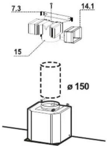
■ Insert the connection extension pieces laterally 14.1 in connection 15.
■ Insert the Connector 15 into the Support bracket 7.3 and fix it with a screw.
■ Make sure that the outlet of the extension pieces 14.1 is horizontally and vertically aligned with the chimney outlets.
■ Connect the air outlet connection 15 to the hood body outlet using either a flexible or rigid pipe ∅ 150 mm, the choice of which is left to the installer.
■ Ensure that the activated charcoal filters have been inserted.
Electrical Connection
■ Connect the hood to the mains through a two-pole switch having a contact gap of at least 3 mm.
■ Remove the grease filters (see paragraph Maintenance) being sure that the connector of the feeding cable is correctly inserted in the socket placed on the side of the fan.

natural_image
Diagram showing a mechanical component with an inset view of a gear shift mechanism (no text or symbols)Fitting the Chimney

Upper chimney
■ Open the two side pieces out slightly, hook them up behind the brackets 7.2.1 and bring them back together again until they are in contact.
■ Fix the upper part of the Chimney to the upper Bracket at the side, using the Screws 12c (2.9 x 9.5) provided.
■ Warning: If it has been extended so far that the lower slots in the upper chimney are level with the holes in the bracket, use the screws 12c provided to fix it; otherwise only use the bottom bracket as a stop for the upper chimney.
Lower Chimney
■ Open out the two Chimney side flaps, hook them up between the upper chimney and the wall and then close them up again until they touch.
- Fix the lower part to the Hood canopy at the sides, using 2 screws 12c (2.9 x 9.5) provided.


| Control Panel | ||
| FunctionsLedButton | ||
| T1 | - | Turns the motor off. |
| Turns the motor on at speed one.Show 1T2 | ||
| Turns the motor on at speed two.Show 2T3 | ||
| T3Timer | The relevant speed LED will flash until the end of the period. | Press and hold for 2 seconds to switch on and off the function Delay.Enable the automatic switch off (motor+lights) delayed of 30 seconds. Useful to remove residual smells. It can be activated when the Intensive speed is turned off; it turns off pressing the button or switching the motor off. |
| Turns the motor on at speed three.Show 3T4 | ||
| T4 | The digits draw circles on the screen | Turns the function Intensive on and off.This speed is timed to run for 10 minutes At the end of this time, the system returns automatically to the speed that was set before. It turns off pressing the button or switching the motor off. It can't be activated when the Delay is turned on. |
| L | - | It turns on/off the two-stage LED lamps at maximum power with just one touch. |
| L | - | When the lamps are turned on/off the 2nd stage (low illumination level) is enabled by pressing on the button for 2 seconds. You can re-adjust the max. level with just one touch. If the lamps are at 2nd stage, to turn them off touch the button twice, or touch and hold for 2 seconds. |
Prior to maintenance, disconnect the appliance or turn the main switch off or remove the fuse that supplies the hood to turn it off.
■ Clean your hood, which is made of stainless steel, with cleaning agents designed specially for this material.
- Do not use metal rubbing materials (wire wool) and abrasive materials (brushes, hard side of the scouring pad etc.).
■ Dry off your hood with a lint-free cloth.
- When sterilizers, products made with carbon steel and other materials containing chloride contact with stainless steel this may cause black shadows, corrosion and permanent stains.
Grease Filters

natural_image
Illustration of a hand pressing down on a grid with a yellow heart symbol (no text or symbols present)Cleaning Metal Self- Supporting Grease Filters
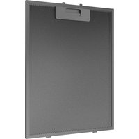
■ The filters must be cleaned every 2 months of operation, or more frequently for particularly heavy usage, and can be washed in a dish-washer.
■ Remove the filters one at a time holding them up with one hand and pulling the handle downwards with the other hand at the same time.
■ Wash the filters, taking care not to bend them. Allow them to dry before refitting.
■ When refitting the filters, make sure that the handle is visible on the outside.
Activated Charcoal Filter (Recirculation Version) Replacing The Activated Charcoal Filter
■ The filter is not washable and cannot be regenerated, and must be replaced approximately every 4 months of operation, or more frequently for particularly heavy usage.
■ Remove the metal grease filters.
■ Remove the saturated activated carbon filter by releasing the fixing hooks.
■ Fit the new filter by hooking it into its seating.
■ Refit the metal grease filters.

natural_image
Illustration of a hand pressing down on a green surface with a green arrow symbol (no text or labels)Lighting unit
Warning: This appliance is fitted with a white LED lamp classed as 1M according to EN 60825-1: 1994 + A1:2002 + A2:2001 standards; maximum optical power emitted @439nm: 7μW. Do not look directly at the light through optical devices (binoculars, magnifying glasses...).
Technical data

This product conforms to European Directives 2004/108/EC, 2006/95/EC, 2009/125/EC and 2011/65/EU.
Power supply
Operating voltage: 230V\~, 50Hz
Technical and design modifications reserved!
Environmental note
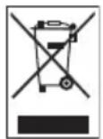
The symbol on the product or on its packaging indicates that this product may not be treated as household waste. Instead it shall be handed over to the applicable collection point for
the recycling of electrical and electronic equipment. By ensuring this product is disposed of correctly, you will help prevent potential negative consequences for the environment and human health, which could otherwise be caused by inappropriate waste handling of this product. For more detailed information about recycling of this product, please contact your local city office, your household waste disposal service or the shop where you purchased the product.
Guarantee for Refrigeration, Cooking Appliance, Washing Machines & Dishwashers
Your new Grundig product is guaranteed against the cost of breakdown repairs for 5 years from the date of the originals purchase.
"Please visit the "support" section on the Grundig website at www.grundig.co.uk to register your 5 year warranty.
What is covered?
- Repairs necessary as a result of faulty materials, defective components or manufacturing defect.
- The cost of functional replacement paris, but excluding consumable items.
- The labour costs of a Grundig approved repairer to carry out the repair.
What is note covered?
- Transil, delivery or accidental damage or misuse and abuse.
- Cabiner or appearance parts, including knobs, flobs, handles or container lids.
- Accessories or consumable items including but not limited to, ice trays, scropers, cutlery baskets, filiers and light bulbs.
- Repairs required as a result of unauthorised repair or inexport installation that fails to meet the requirements contained in the user instruction book.
• Repairs to products used on commercial or non residential household premises. - Loss of frozen food in freezers or fridge/freezers. (Food loss insurance is often included within your household contents insurance policy, or may be available separately from your retailer.)
Important notes
- Your Grundig product is designed and built for domestic household use only.
- the guarantee will be void if the product is installed or used in commercial or non-residential domestic household premises.
- The product must be correctly installed, located and operated in accordance with the instructions contained in the User Instructions Booklet provided.
• Professional installation by a qualified Electrical Domestic Appliance Installer is recommended for all Washing Machines, Dishwashers and Electric Cookers - Gas Cookers must only be installed by a Gas Safe (or BORD GAIS) registered Gas Intaller.
- The guarantee is given only within the boundaries of the United Kingdom and the Republic of Ireland.
- The guarantee is applicable only to new products and is note transferable if the product is resold.
- Grindig disclaims any liability for incidental or consequential damages.
- The guarantee does not in anyway diminish your statutory or legal rights.
Should you experience any difficulty in obtaining service please contact the Grundig Customer Helpline.
Tel : 0845 603 1234
0345 603 1234
e-mail : service@Grundig.co.uk
Please keep your purchase receipt or other proof of purchase in a safe place; you will need to have it should the product require attention under guarantee.
You should also complete the details below; it will help us assist you when requesting service. (The model number is printed on the Instruction Booklet and the serial number is printed on the Rating Label affixed to the appliance)
Model No:
Serial No:
Retailer:
Date of purchase:
For service under guarantee simply telephone the appropriate number below UK Mainland & Northern Ireland
0845 603 1234
0345 603 1234
Republic of Ireland
All Refrigeration, All Cookers
Washing Machines and Dishwashers
01 862 34 11
Before requesting service please check the trouble-shooting guide in the Operating Instructions as a charge may be levied where no fault is found even though your product may still be under guarantee. Service once the manufacturers guarantee has expired.
If you have purchased an extended guarantee please refer to the instructions contained within the extended guarantee agreement document. Otherwise please call the appropriate number above where service can be obtained at a charge.
Grundig, 1 Greenhill Crescent, Watford Herts WD18 8QU
FOR A GOOD REASON
GRUNDIG

- Please read this user manual first!
- TABLE OF CONTENTS
- Safety and set-up 6-7
- At a glance 8
- Operation 9-12
- Information 15
- Guarantee 16
- Service 17
- Installation
- Use
- Maintenance
- Control, parts and accessories
- Ref. Q.ty Product Components
- Ref. Q.ty Installation Components
- Q.ty Documentation
- Connection Of Motor Unit/Hood
- Wall drilling and bracket fixing
- Mounting the hood body
- Connections
- Ducted Version Air Exhaust System
- Recirculation Version Air Outlet
- Electrical Connection
- Fitting the Chimney
- Upper chimney
- Lower Chimney
- Grease Filters
- Cleaning Metal Self- Supporting Grease Filters
- Activated Charcoal Filter (Recirculation Version) Replacing The Activated Charcoal Filter
- Lighting unit
- Technical data
- Power supply
- Environmental note
- Guarantee for Refrigeration, Cooking Appliance, Washing Machines & Dishwashers
- "Please visit the "support" section on the Grundig website at www.grundig.co.uk to register your 5 year warranty.
- What is covered?
- What is note covered?
- Important notes
Brand : GRUNDIG
Model : GDK5792
Category : Range hood