
PDS-1615R - Audiovisual Equipment Middle Atlantic - Free user manual and instructions
Find the device manual for free PDS-1615R Middle Atlantic in PDF.


| Product Type | Sequenced Multi-Mount Power Strip |
| Brand | Middle Atlantic |
| Model | PDS-1615R |
| Category | Audiovisual Equipment |
| Mounting | 19-inch EIA-310 rackmount with adjustable mounting ears (standard and extra depth) |
| Dimensions (approx.) | 19" width x 1.75" height x 9" depth (typical 1U rack unit) |
| Weight (approx.) | 5 lbs (2.3 kg) |
| Input Voltage | 120V AC |
| Power Cord | 9 ft (2.7 m), 14 AWG, 3-conductor with NEMA 5-15P plug |
| Circuit Breaker | 15 Amp, rear-mounted |
| Rear Outlets | 10 unswitched NEMA 5-15R |
| Front Outlets | 6 sequenced NEMA 5-15R (3 steps, 2 outlets per step) |
| Sequencing Steps | 3 |
| Sequence Delay Options | 0, 1, 2, 6, 10, 30, 60, or 90 seconds |
| Control Type | Local/Remote switch with dry contact terminals (Sequence Up/Down, Sequence Complete) |
| Surge Protection | 2-stage with N/O dry contact surge status notification |
| Power Indication | LED on front panel |
| Surge Protection Indication | 2 LEDs; both lit indicates full protection |
| Sequence Status LEDs | Per outlet step (front) |
| Safety Certifications | FCC Class B, UL listed (implied) |
| Operating Environment | Indoor, dry location |
| Warranty | See manufacturer's website |
Frequently Asked Questions - PDS-1615R Middle Atlantic
User questions about PDS-1615R Middle Atlantic
0 question about this device. Answer the ones you know or ask your own.
Ask a new question about this device
Download the instructions for your Audiovisual Equipment in PDF format for free! Find your manual PDS-1615R - Middle Atlantic and take your electronic device back in hand. On this page are published all the documents necessary for the use of your device. PDS-1615R by Middle Atlantic.
USER MANUAL PDS-1615R Middle Atlantic
SEQUENCED MULTI-MOUNT™
THANK YOU
Thank you for purchasing Sequenced Multi-Mount™ Series Power. Please read these instructions thoroughly before installing and connecting to this product.
SEQUENCED MULTI-MOUNT POWER FEATURES
- 3 Step sequencing with multiple delay options
- Universal sequence control
- 2 Stages of surge and spike protection with dry contact surge status notification based on model
- Provides a high outlet density in a compact size
- Adjustable mounting ears for flexible installation options
- Mixed outlet spacing to accommodate various plug types
IMPORTANT SAFETY INSTRUCTIONS
READ AND SAVE THESE INSTRUCTIONS! CONSERVER CES INSTRUCTIONS!
- Contains switched receptacle(s). To reduce risk of shock, disconnect the device from the power source before servicing any connected equipment
- Do not overload the wall outlet where this device is being connected. Do not overload this device. Ensure the total load to this device does not exceed that which is listed in the specifications section of this manual
- Ensure this device is connected to a properly grounded AC power source. Ensure the device is plugged into a source providing the required 120V. Do not use a plug adapter that defeats the ground pin of the AC plug
- There are no user-serviceable components within this device. Removal of the cover from this device may present a shock hazard, and void the warranty
• To be used indoors in a dry location only
- Do not operate with a damaged cord or plug
- Clean only with dry cloth
The lightning flash with the arrowhead symbol, within an equilateral triangle is intended to alert the user to the presence of uninsulated dangerous voltage within the product's enclosure that may be of sufficient magnitude to constitute a risk of electric shock to persons.
The exclamation point within an equilateral triangle is intended to alert the user to the presence of important operating and maintenance (servicing) instructions in the literature accompanying the appliance.
This equipment has been tested and found to comply with the limits for a Class B digital device, pursuant to PART 15 of the FCC Rules. These limits are designed to provide reasonable protection against harmful interference in a residential installation. This equipment generates, uses and can radiate radio frequency energy and, if not installed and used in accordance with the instructions, may cause harmful interference to radio communications. However, there is no guarantee that interference will not occur in a particular installation. If this equipment does cause harmful interference to radio or television reception, which can be determined by turning the equipment off and on, the user is encouraged to try to correct the interference by one or more of the following measures:
- Reorient or relocate the receiving antenna.
- Increase the separation between the equipment and receiver.
- Connect the equipment into an outlet on a circuit different from that to which the receiver is connected.
- Consult the dealer or an experienced radio/TV technician for help.
IMPORTANT NOTES
- Install power strip in a 19" EIA-310 compliant rack or cabinet.
NOTE: The MAINS plug or an appliance coupler is used as the disconnect device, the disconnect device shall remain readily operable. The socket-outlet shall be installed near the equipment and shall be easily accessible.
SEQUENCED MULTI-MOUNT FEATURE CHART
| Part # | Circuit Breaker | # Rear outlets | # Front outlets | # Sequence steps | # outlets per step | Sequence delay (in Sec) | Cord length | Breaker Location | Power on Indication | Surge Protection |
| PDS-1615R One Amp | 10(Unswitched) | 6(Sequenced) | 3 | 2, with LED Status | 0, 1, 2, 6, 10, 30, 60, 90 | 9' | Rear | LED on Front | 2 stage with N/O remote dry contact notification | |
| PDS-1620R-NS | One 20 Amp | 10(Unswitched) | 6(Sequenced) | 3 | 2, with LED Status | 0, 1, 2, 6, 10, 30, 60, 90 | 9' | Rear | LED on Front | N/A |
PDS-1615R
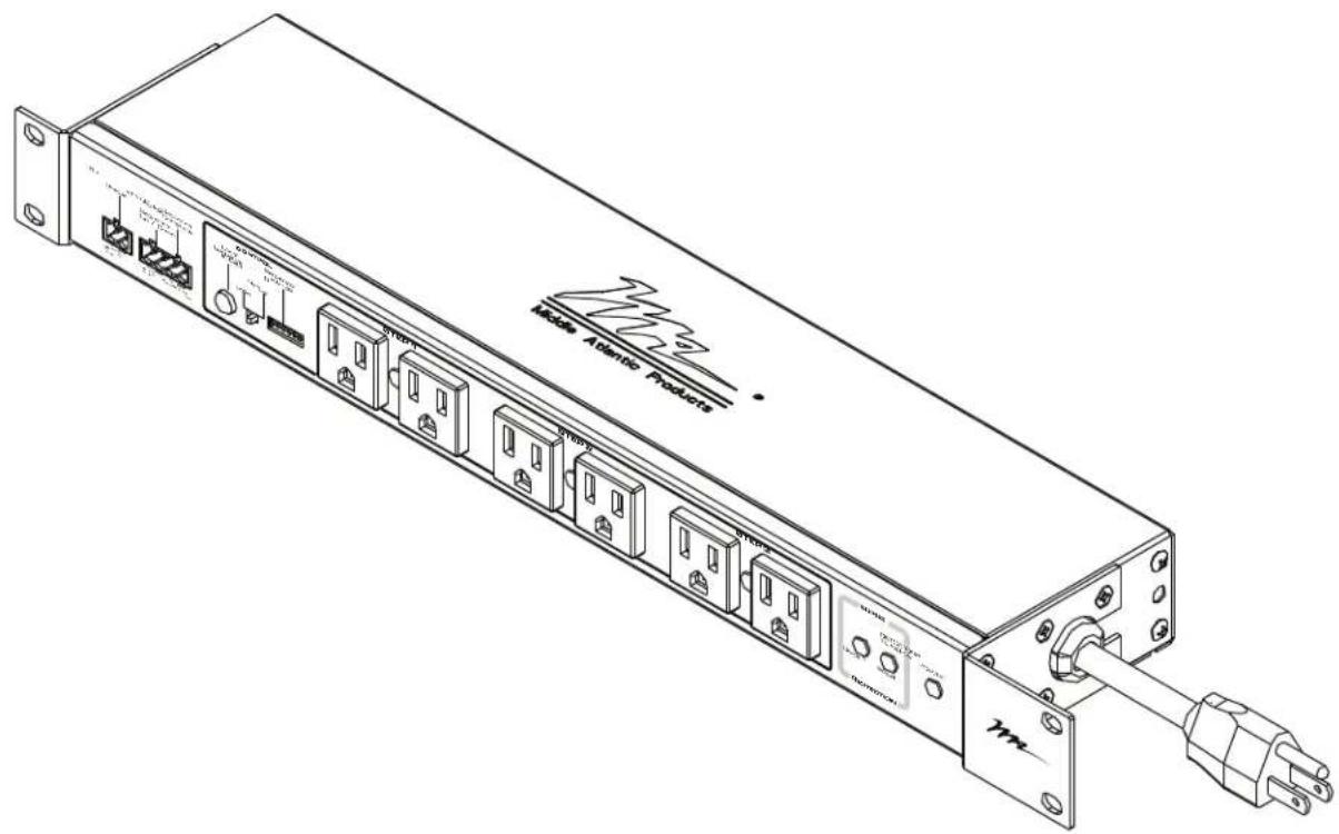
FRONT VIEW

REAR VIEW

① SURGE PROTECTION STATUS - "Normally Open" remote notification dry contact, closed if compromised
② SEQUENCE UP / DOWN TERMINALS - Remote initiate
③ SEQUENCE COMPLETE TERMINALS - Closed on sequence power up, Open on sequence power down.
④ LOCAL SEQUENCE INDICATOR - Only active when "Local / Remote" switch set to "Local"
⑤ LOCAL / REMOTE SWITCH - "Local" to enable local sequence initiate switch / "Remote" to enable dry contact sequence control
⑥ SEQUENCE SETTINGS - Set sequence delay and control type. For more information, see "Sequence Control Options" on page 5.
⑦ NEMA 5-15R SEQUENCED OUTLETS - 3 Steps, 2 outlets per step. Power status LEDs
⑧ 2 STAGE SURGE PROTECTION INDICATOR - Full protection when both LEDs are lit. Protection is compromised if one or both LEDs are not lit
9 POWER INDICATOR LIGHT - When lit, indicates unit is energized
10 9', 14 AWG, 3 CONDUCTOR (SignalSAFE™) POWER CORD WITH NEMA 5-15P PLUG
15 AMP CIRCUIT BREAKER - Provides protection for both front and rear outlets
⑫ SUPPLEMENTAL BONDING POINT - Supplemental bonding of this unit to the metal rack / enclosure helps ensure optimum performance of your electronic system
13 NEMA 5-15R OUTLETS - All rear outlets unswitched
PDS-1620R-NS
FRONT VIEW

REAR VIEW

① SEQUENCE UP / DOWN TERMINALS - Remote initiate
② SEQUENCE COMPLETE TERMINALS - Closed on sequence power up, Open on sequence power down.
③ LOCAL SEQUENCE INDICATOR / SWITCH - Only active when "Local / Remote" switch set to "Local"
④ LOCAL / REMOTE SWITCH - "Local" to enable local sequence initiate switch / "Remote" to enable dry contact sequence control
⑤ SEQUENCE SETTINGS - Set sequence delay and control type. For more information, see "Sequence Control Options" on page 5.
⑥ NEMA 5-20R SEQUENCED OUTLETS - 3 Steps, 2 outlets per step. Power status LEDs
⑦ POWER INDICATOR LIGHT - When lit, indicates unit is energized
⑧ 9', 12 AWG, 3 CONDUCTOR (SignalSAFE™) POWER CORD WITH NEMA 5-20P PLUG
20 AMP CIRCUIT BREAKER - Provides protection for both front and rear outlets
⑩ SUPPLEMENTAL BONDING POINT - Supplemental bonding of this unit to the metal rack / enclosure helps ensure optimum performance of your electronic system
⑪ NEMA 5-20R OUTLETS - All rear outlets unswitched
SEQUENCE CONTROL OPTIONS
SEQUENCE DELAY SETTINGS
| Sequence Interval: No Delay | Sequence Interval: Ten Seconds |
| Sequence Interval: One Second | Sequence Interval: Thirty Seconds |
| Sequence Interval: Two Seconds | Sequence Interval: Sixty Seconds |
| Sequence Interval: Six Seconds | Sequence Interval: Ninety Seconds |
REMOTE SETTINGS

Normally Closed - Sequence up on contact opening.
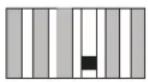
Normally Open - Sequence up on contact closure.
⚠️ To sequence units up when power is restored from a total power loss:
- Set DIP switch to Normally Open
- Connect a single pole, momentary, normally closed dry contact to the SEQUENCE UP/DOWN TERMINALS
NOTE: If local sequence control is not required, short the SEQUENCE UP/DOWN TERMINALS together

Momentary Operation
Sequence up or down (depending on state) when remote control contact is toggled.

Maintained Operation
For normally open mode sequence up when remote control contact is closed sequence down when remote control contact is opened. For normally closed mode sequence up when remote control contact is open sequence down when remote control contact is closed.

Sequence Complete Status
Contact closes upon completion of sequence cycle on and opens after completion of sequence off.

Step 4
Contact becomes a 4th step in the sequence cycle on and off, contact closes last with a sequence on and opens first with sequence off.
CONTINUED ON NEXT PAGE
- While using remote sequencing dry contact terminals, be sure to use the appropriate settings for whichever contact closure system you are implementing. Failure to do so may result in improper operation.
Ex: Do not attempt to control the unit using a ‘maintained’ switch while in ‘momentary’ mode.
Ex: Unless you are using a ‘normally closed’ ‘momentary’ switch, make sure your system is set for ‘normally open’ when operating in ‘momentary’ mode.
CONTROLLING MULTIPLE UNITS
The remote control option is controlled via a user provided dry contact closure. Multiple sequencers can be controlled by one switch in either a daisy chain fashion or simultaneously. 'Momentary' or 'maintained', 'normally open' or 'normally closed' settings will vary based on the method selected. See below for details.
There are two connection methods when multiple sequencers are to operate as one system;
The first method is to have multiple units operate in succession in a daisy chain fashion. This can be implemented by connecting the 'Sequence Complete Status' terminals of the first unit to the 'Sequence Initiate terminals' of the next unit. The first unit must have its 'momentary' or 'maintained' and 'normally open' or 'normally closed' settings set based on the switch or control system. All proceeding units must be set to operate in a 'normally open', 'maintained' format. The notification system for this method should be used at the very end of the "chain" to verify the end status for all units. (see Diagram A)
NOTE: the last channel of the first unit and the first channel of the second unit will turn on simultaneously because there is no delay on the sequence status terminals.
The second method is in a parallel fashion so that the sequencing of the units begins simultaneously. Simply connect the units in parallel to the control system or switch. All units must have their ‘momentary’ or ‘maintained’ and ‘normally open’ or ‘normally closed’ settings set identically based on the switch or control system.
It is recommended that each unit has its own notification system in this setup to verify the status of each unit. (see Diagram B)
Note that Delay Time Settings affect units individually.
Diagram A
Daisy Chain

flowchart
graph TD
    A["Control System"] --> B["Sequence Up/Down"]
    A --> C["Sequence Complete"]
    B --> D["Remote Initiate"]
    C --> E["Closed On Sequence Complete"]
    D --> F["Sequence Up/Down"]
    E --> G["Sequence Complete"]
    F --> H["To Next Unit/Notification System"]
    G --> I["Sequence Up/Down"]
    H --> J["Sequence Complete"]
    I --> K["Remote Initiate"]
    J --> L["Closed On Sequence Complete"]
Diagram B
Simultaneously

flowchart
graph TD
    A["Control System"] --> B["Sequence Up/Down"]
    A --> C["Sequence Complete"]
    B --> D["Remote Initiate"]
    C --> E["Closed On Sequence Complete"]
    F["Notification System"] --> G["Sequence Up/Down"]
    F --> H["Sequence Complete"]
    I["To Next Unit"] --> J["Remote Initiate"]
    I --> K["Closed On Sequence Complete"]
    L["Notification System"] --> M["Sequence Up/Down"]
    L --> N["Sequence Complete"]
FLEXIBLE MOUNTING OPTIONS USING STANDARD OR EXTRA DEPTH MOUNTING EARS
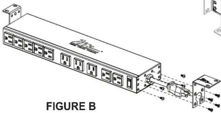
NOTE: Mounting ears (standard or extra depth) can be rotated in 90° increments for a variety of mounting positions (FIGURE A).
1) Remove screws and rotate both mounting ears to desired position. Re-insert screws and tighten.
2) Install screws when positioned at 90° angle to cap unused holes (FIGURE B).

natural_image
Technical line drawing of a server rack with ports and connectors, labeled as FIGURE B (no text or symbols on the diagram itself)(STANDARD MOUNTING EARS SHOWN)

natural_image
Technical line drawing of a rack-mounted server unit with multiple ports and mounting brackets (no text or symbols)
natural_image
Technical line drawing of a server rack with mounting holes and internal components (no text or symbols)(EXTRA DEPTH MOUNTING EARS SHOWN)
FLEXIBLE MOUNTING OPTIONS USING STANDARD OR EXTRA DEPTH MOUNTING EARS (Continued)
3) Optional RBA-Series rail bracket adapters and vertical lacer strips (sold separately) allow the Multi-Mount Power unit to be vertically mounted between the rail brackets of WRK, MRK and VRK racks. The use of LACE Series vertical lacer strips is recommended to aid with cable management.

WARRANTY
For warranty information, refer to http://www.middleatlantic.com/company/about-us.aspx#warranty
Corporate Headquarters
Corporate Voice: 973-839-1011 - Fax: 973-839-1976 / International Voice: +1 973-839-8821 -
Middle Atlantic Canada
Voice: 613-836-2501 - Fax: 613-836-2690 / ca.middleatlantic.com -
customerservicecanada@middleatlantic.ca
Factory Distribution
USA: NÍJ - CA - IL Canada: ON
At Middle Atlantic Products we are always listening. Your comments are welcome.
Middle Atlantic Products is an ISO 9001 and ISO 14001 Registered Company.
- SEQUENCED MULTI-MOUNT™
- THANK YOU
- SEQUENCED MULTI-MOUNT POWER FEATURES
- IMPORTANT SAFETY INSTRUCTIONS
- READ AND SAVE THESE INSTRUCTIONS! CONSERVER CES INSTRUCTIONS!
- IMPORTANT NOTES
- PDS-1620R-NS
- SEQUENCE CONTROL OPTIONS
- Momentary Operation
- Maintained Operation
- Sequence Complete Status
- Step 4
- CONTROLLING MULTIPLE UNITS
- FLEXIBLE MOUNTING OPTIONS USING STANDARD OR EXTRA DEPTH MOUNTING EARS
- FLEXIBLE MOUNTING OPTIONS USING STANDARD OR EXTRA DEPTH MOUNTING EARS (Continued)
- WARRANTY
- Corporate Headquarters
- Middle Atlantic Canada
- Factory Distribution
Brand : Middle Atlantic
Model : PDS-1615R
Category : Audiovisual Equipment