
GS7 - Fitness Equipment CORTEX - Free user manual and instructions
Find the device manual for free GS7 CORTEX in PDF.


| Product Type | Multi-Station Home Gym |
| Brand | Cortex |
| Model | GS7 |
| Main Functions | Chest press, butterfly, leg extension, lat pulldown, low row, squat, arm curl, and more |
| Weight Stack | 12 weight plates (individual weight not specified; user adjustable via selector pin) |
| Number of Stations | Multiple exercise stations in one unit |
| Cable System | Dual wire rope with pulleys for smooth operation |
| Frame Material | Steel with welded construction |
| Seat and Pad Adjustments | Adjustable back cushion, seat cushion, and elbow pads |
| Safety Features | Weight pin selector; spotter recommended; flat surface requirement; keep children away |
| Required Assembly | Yes, detailed assembly steps in manual (recommended by two people) |
| Maintenance | Lubricate moving joints with silicone spray; check wire rope tension; tighten bolts regularly |
| Spare Parts Availability | Parts list with key numbers; available via manufacturer's website or after-sales service |
| Warranty | Covered under Australian Consumer Law; full terms at lifespanfitness.com.au |
| Manufacturer | Lifespan Fitness (for Cortex) |
Frequently Asked Questions - GS7 CORTEX
User questions about GS7 CORTEX
0 question about this device. Answer the ones you know or ask your own.
Ask a new question about this device
Download the instructions for your Fitness Equipment in PDF format for free! Find your manual GS7 - CORTEX and take your electronic device back in hand. On this page are published all the documents necessary for the use of your device. GS7 by CORTEX.
USER MANUAL GS7 CORTEX
GS7 Multi Station Home Gym
USER MANUAL

natural_image
Technical line drawing of a mechanical exercise machine (no text or symbols present)Product may vary slightly from the item pictured due to model upgrades.

Read all instructions carefully before using this product. Retain this owner's manual for future reference.
NOTE:
This manual may be subject to updates or changes. Up to date manuals are available through our website at www.lifespanfitness.com.au
TABLE OF CONTENTS
I. Important Safety Instructions 03
II. Care Instructions 04
III. Parts List 05
IV. Assembly Instructions 09
V. Maintenance Instructions 23
VI. Exercise Guide 24
VII. Warranty 26
I. IMPORTANT SAFETY INSTRUCTIONS

WARNING: Read all instructions before using this machine.
• Install the product on a flat level surface.
- Place your unit on a solid, level surface when in use.
- Never allow children on or near the machine.
- Keep hands away from all moving parts.
- Never drop or insert any object into any openings.
- Care must be taken when lifting or moving the equipment so as not to injure your back. Always use proper lifting techniques and/or seek assistance if necessary.
- Keep children and pets away from the machine at all times. DO NOT leave children unattended in the same room with the machine.
- Only 1 person at a time should use the machine.
- If the user experiences dizziness, nausea, chest pain, or any other abnormal symptoms, STOP the workout at once. CONSULT A PHYSICIAN IMMEDIATELY
- Do not use the machine near water or outdoors.
- Keep hands away from all moving parts.
- Always wear appropriate workout clothing when exercising. DO NOT wear robes or other clothing that could become caught in the machine. Running or aerobic shoes are also required when using the machine.
- Use the machine only for its intended use as described in this manual. DO NOT use attachments not recommended by the manufacturer.
- Do not place any sharp objects around the machine.
- Disabled person should not use the machine without a qualified person or physician in attendance.
- Never operate the machine if the machine is not functioning properly.
- A spotter is recommended during exercise.
II. CARE INSTRUCTIONS
- Lubricate moving joints with silicone spray after periods of usage.
- Be careful not to damage plastic or metal parts of the machine with heavy or sharp objects.
- The machine can be kept clean by wiping it down using a dry cloth.
- Check and adjust the tension of wire rope on a regular basis.
- Regularly check all moving parts and make sure there are no signs of wear and damage, if any the use of the device must be stopped immediately and contact our after-sales department.
- During inspection, it is necessary to make sure that all bolts and nuts are tightened completely. If any bolt or nut connection is loosened, please re-tighten.
- Check weld for cracks.
- Failure to perform daily maintenance may result in personal injury or equipment damage.

Caution: Please always check your chain links parts (77 and 79) are fully tightened or clipped in properly before use as this may cause injury if the links are not screwed all the way or clipped properly.
III. PARTS LIST
Key No. Description Qty.
| 1 Post to the ground 1 | ||
| 2 Before the ground 1 | ||
| 3 Boat Patch Ground Welding 1 | ||
| 4 T Post Ground 1 | ||
| 5 Checkered Plate 1 | ||
| 6 Small Paste Ground 2 | ||
| 7 Guide Rod 2 | ||
| 8 Plus Rod 1 | ||
| 9 Select Rod 1 | ||
| 10 | Upright Column | 1 |
| 11 | Pillow Block Bearing | 1 |
| 12 | Leg Arm | 1 |
| 13 | Top Tube | 1 |
| 14 | Even Frame | 1 |
| 15 | Left Butterfly Arm | 1 |
| 16 | Right Butterfly Arm | 1 |
| 17 | Supper Control Frame | 1 |
| 18 | Elbow Pad Control Frame | 1 |
| 19 | Back Cushion 1 | |
| 20 | Seat Cushion 1 | |
| 21 | Elbow Cushion | 1 |
| 22-1 | Pull Up Wire Rope | 1 |
| 22-2 | Low Pull Wire Rope | 1 |
| 22-3 | Butterfly Arm Wire Rope | 1 |
| 23 | Pulley | 18 |
| 24 | Handle | 1 |
| 25 | Low Pull Handle | 1 |
| 26 | Big Head Rope | 1 |
| 27 | Boating Pipe | 1 |
| 28 | Bubble Cotton Tube | 2 |
Key No. Description Qty.
| 29 | Foam (Φ100x175) | 4 |
| 30 | Left Plate Cover | 1 |
| 31 | Right Plate Cover | 1 |
| 32 | Upper Beam Welded | 2 |
| 33 | Bumper Column | 1 |
| 34 | Curved Tube | 1 |
| 35 | Lead Handle | 1 |
| 36 | Bumper Left Arm | 1 |
| 37 | Bumper Right Arm | 1 |
| 38 | Bumper Vertical Handle | 2 |
| 39 | Down-to-foot Welding | 1 |
| 40 | Squat Column Frame | 1 |
| 41 | Plate Holder | 2 |
| 42 | Squat Small Connection Welding joint | 1 |
| 43 | Squat Outside Adjustment | 1 |
| 44 | Squat Inside Adjustment | 1 |
| 45 | Squat Arm Joint Welding Joint 1 | |
| 46 | Squat Arm Welding | 1 |
| 47 | Squat Arm Welding A | 1 |
| 48 | Top Cable Cover | 2 |
| 49 | Bumper Back Cushion | 1 |
| 50 | Bumper Elbow Pad | 2 |
| 51 | Squat Pad | 2 |
| 52 | Squat Pad | 2 |
| 53-1 | Pulley Block | 2 |
| 53-2 | Slider Adjustment Plate | 2 |
| 53-3 | Plate | 9 |
| 53-4 | Cross Pulley Block | 1 |
| 53-5 | Weight Lock | 1 |
Key No. Description Qty.
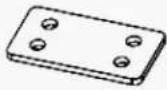
| 53-6 4 Holes Plate 1 | |
| 53-7 25 Butterfly Card 2 | |
| 53-8 Spin Axis (57mm) 4 | |
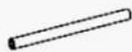
| 53-9 Spin Axis (100mm) 1 | |
| 53-10 Spin Axis (208mm) 1 | |
| 54-1 Weight Loss Pad 2 | |
| 54-2 Knob Pin M16 1 | |
| 54-3 Foam Plug 4 | |
| 54-4 Knob Pin M18 | 2 |
| 54-5 Slider Liner | 8 |
| 54-6 Weight Limit | 2 |
| 54-9 Chain 200mm | 1 |
| 54-10 Chain 400mm | 1 |
| 54-11 C Type Buckle | 4 |
| 54-12 Calabash Hook | 1 |
| 55 Pull the Handle | 2 |
| 56-1 Bolt M10*90 20 | |
Key No. Description Qty.
| 56-2 Bolt M10*70 | 18 | |
| 56-3 Bolt M10*20 20 | ||
| 56-4 Bolt M10*45 | 16 | |
| 56-5 Bolt M10*60 | 4 | |
| 56-6 Bolt M8*10 | 4 | |
| 56-7 Bolt M8*16 | 16 | |
| 56-8 Bolt M8*40 | 2 | |
| 56-9 Bolt M8*65 | 4 | |
| 56-10 Bolt M8*85 | 4 | |
| 56-11 | Bolt M8*100 | 8 |
| 56-12 | 10 Flat Gasket | 176 |
| 56-13 | 10 Increase the Flat Pad | 6 |
| 56-14 | M10 Locknut | 60 |
| 56-15 | M8 Plain nut | 6 |
| 56-16 | Bolt M6*10 3 | |
| 56-17 | M6 Plain Nut | 3 |
| 57 | Weight | 12 |

53-1 53-2 53-3 53-4 53-5


53-6 53-7 53-8 53-9 53-10


54-1 54-2 54-3 54-4 54-5


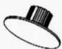


54-6 54-9 54-10 54-11 54-12
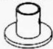


56-1 56-2 56-3 56-4 56-5
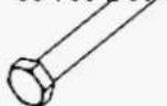
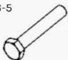


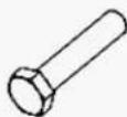
56-6 56-7 56-8 56-9 56-10


56-11

56-12

56-13
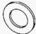
56-14

56-15

56-16

56-17

IV. ASSEMBLY INSTRUCTIONS
! ATTENTION:
- The gasket shall be placed at both ends of the bolts (against the bolt head and nut), if indicated otherwise.
- Preliminary assembly is hand tightening all bolts and nuts and tightening with wrench for complete assembly.
- Some spare parts have been pre-assembled in the factory.
- This product is recommended to install by more than two people.

STEP 1 - INSTRUCTIONS
- Place the bolts (#56-2) and the gaskets (#56-12) from below the part (#1) as shown.
-
Place (#2) and (#4) on both sides of (#1) as shown, and secure with:
-
Bolts (#56-1)
- Gaskets (#56-12)
-
Nuts (#56-14)
-
Place two (#6) on both sides of (#2) as shown, and secure them with:
-
Bolts (#56-1)
- Spacers (#56-12)
-
Nuts (#56-14)
-
Connect part (#3) to part (#2) with:
-
Bolts (#56-1)
- Gaskets (#56-12)
-
Nuts (#56-14) as shown
-
Pre-install bolts (#56-2), gaskets (#56-12) onto (#2) in advance.
- Install (#5) to (#3) as shown and connect it with (#27).

STEP 2
- With three holes facing up, insert (#7) into the (#1) and secure with mounting hole with:
- 2 Bolts (#56-3)
- 2 spacers (#56-12)
Then insert (#54-1) into (#7).
-
Place the counterweight block (#57) into (#7) one by one (Note that the counterweight block groove joint is uniformly facing down).
-
Insert the plus bar (#8) in the middle of the (#41) hole.
-
Install the counterweight head (#9) to (#7), then install (#54-6) to (#7) and secure it with:
- Bolts (#56-4)
- Nuts (#56-14)

NOTE: The direction of the weight block gap (the weight pin) must face down.

STEP 3
-
Lock the lower end of (#10) and (#2) with:
-
2 Pads (#56-12)
-
2 Nuts (#56-14)
-
Set (#11) into the (#2) pre-installed bolt first, and lock it with:
-
2 Spacers (#56-12)
-
2 Nuts (#56-14)
-
Connect (#11) to (#10) by (#53-3) with:
-
Bolts (#56-1)
- Gasket (#56-12)
-
Nuts (#56-14)
-
Install (#53-8) into (#12) and ends on (#11) with bolts (#56-3) and pads (#56-12).
- Install the (#53-1) bolts (#56-2), gasket (#56-12), and nut (#56-14) on the (#10) U frame.

STEP 4
- Cover (#7) into the (#13) rear square tube mounting hole as shown, secure with:
- Bolts (#56-3)
- Gasket (#56-12)
- Connect (#53-3) to (#13) and (#13) to (#10) with:
- Bolts (#56-1)
- Gaskets (#56-12)
- Nuts (#56-14)
- Install (#53-9) into (#13) and install (#14) on (#13) with:
- Bolts (#56-3)
- Pads (#56-12)
- Apply (#15) into (#14) and lock with:
- Gasket (#56-13)
- Nut (#56-14)
- Secure part (#55) to part (#15) and (#16) as shown in diagram.
STEP 5
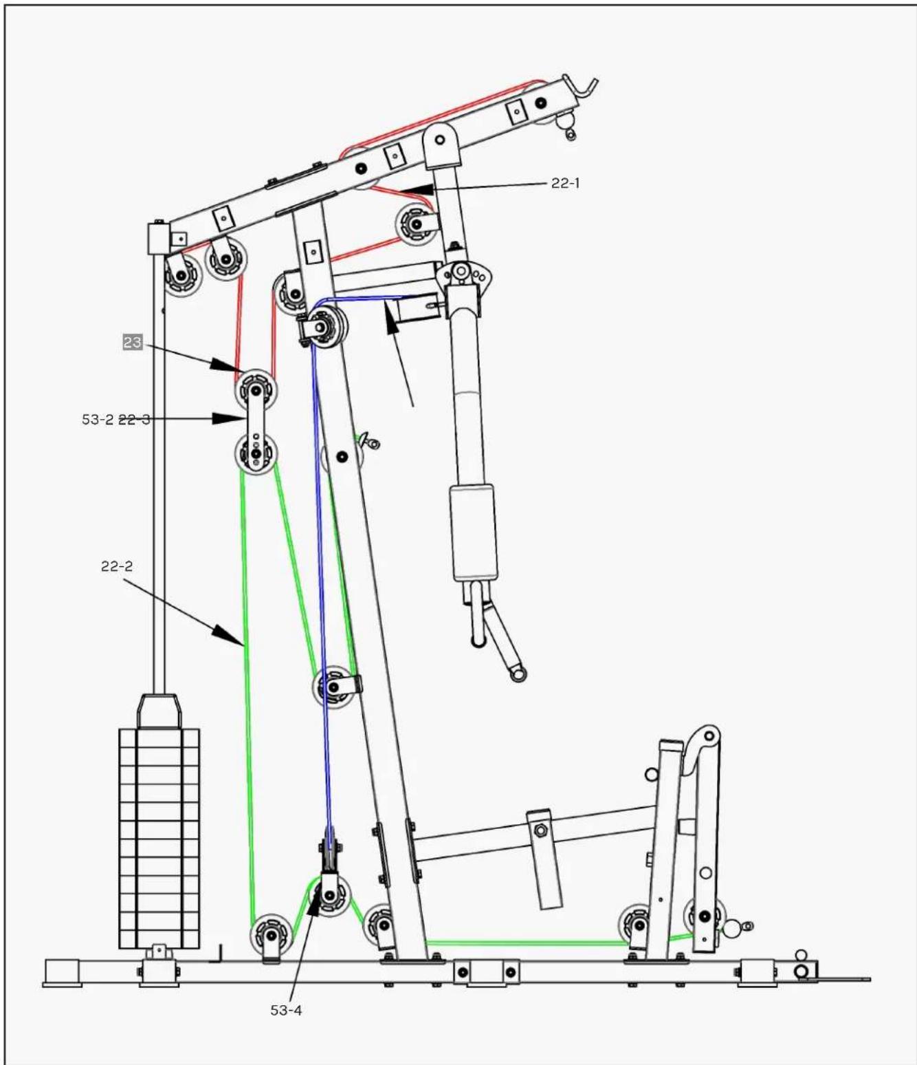
After the whole instrument is assembled, check if the wire rope is tightened. If the wire rope is slightly loose, adjust by tightening the lower bolts of the tensile wire rope (#22-1). If the wire rope is loose, adjust the pulley mounting hole position adjustment through the pulley adjustment sheet (#53-2).
NOTE: Wire rope must be fed into the pulley before securing the pulley.

STEP 6
NOTE: Wire rope must be fed into the pulley before securing the pulley.

STEP 7
-
Install (#19) to (#10) with:
-
2x Bolts (#56-9)
-
2x Gaskets (#56-12)
-
Install (#20) to (#17) with:
-
2x Bolts (#56-8)
-
2x Spacers (#56-12)
-
Install (#21) to (#18) with:
-
2x Bolts (#56-7)
-
2x Spacers (#56-12)
-
Install the installed (#17) to (#11) and lock with (#54-4).
-
Then install (#18) to (#11) and lock with (#54-4).
STEP 8
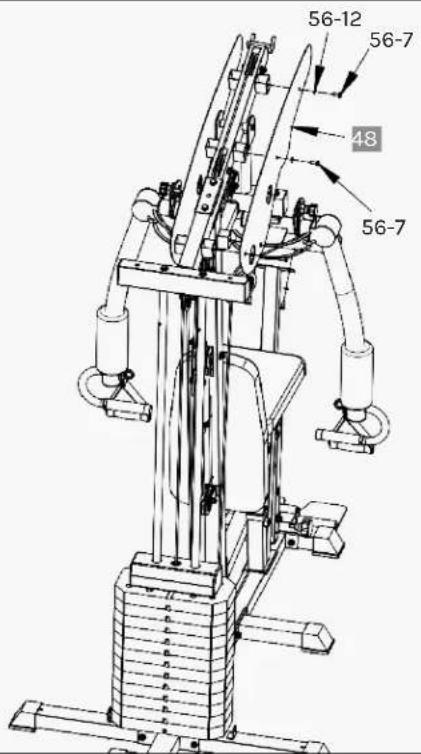
- Place (#48) on (#13) side and secure with (#56-7) bolts and (#56-12) gaskets.
STEP 9
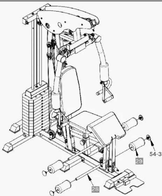
- Insert (#28) foam pipe into (#12), then insert from pipe head to (#29) and (#54-3) onto (#28).

STEP 10
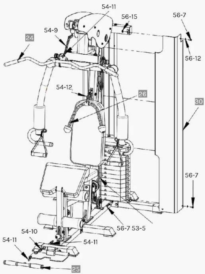
- Install parts (#30) and (#31) with (#56-7) nuts, (#56-12) gaskets and (#56-15) bolts onto parts (#13), (#1) and (#2).
Attach the accessories and weight pin:
- Connect (#54-10) to 2x (#54-11) on each end then secure (#54-11) to (#25) and the other side to the bottom cable wire.
- Connect (#54-12) to the middle cable wire and the other end to (#26).
- Connect (#54-10) to 2x (#54-11) on each end then secure (#54-11) to (#24) and the other end secure to the top cable wire.
- Insert (#53-5) into the counterweight block to change your desired weight loading.

NOTE: Make sure to secure (#54-11) and (#54-12) properly when swapping accessories.

STEP 11
-
Install (#35) on (#34) and secure it with:
-
Bolts (#56-2)
- Bolts (#56-3)
- Flat spacers (#56-12)
-
Nuts (#56-14)
-
Install (32) on (#13) as shown, and secure it with:
-
Plate (#53-3)
- Bolts (#56-1)
- Flat spacers (#56-12)
-
Nuts (#56-14)
-
Install (#39) on (#33) and tighten it with:
-
Bolts (#56-1)
- Flat spacers (#56-12)
- Nuts (#56-14)
-
Plate (#53-3)
-
Install the installed (#33) on (#1) and tighten it with:
-
Flat pads (#56-12)
-
Nut (#56-14)
-
Install the installed (#34) into (#33) as shown and connect to (#32) with:
-
Plate (#53-3)
- Bolts (#56-1)
- Flat pads (#56-12)
- Nuts (#56-14) and tighten.

STEP 12
-
Install (#36) and (#37) to (#33) and secure with:
-
Bolts (#56-2)
- Flat spacers (#56-12)
- Nuts (#56-14)
- Plate (#53-6)
- Washer (#56-12)
-
Bolts (#56-6)
-
Secure (#38) to (#36) and (#37) using:
-
Bolts (#56-3)
-
Washer (#56-12)
-
Install (#50) to (#36) and (#37)
respectively with:
- Bolts (#56-9)
-
Flat spacers (#56-12)
-
Install (#49) to (#33) with:
-
Bolts (#56-10)
- Flat spacers (#56-12)
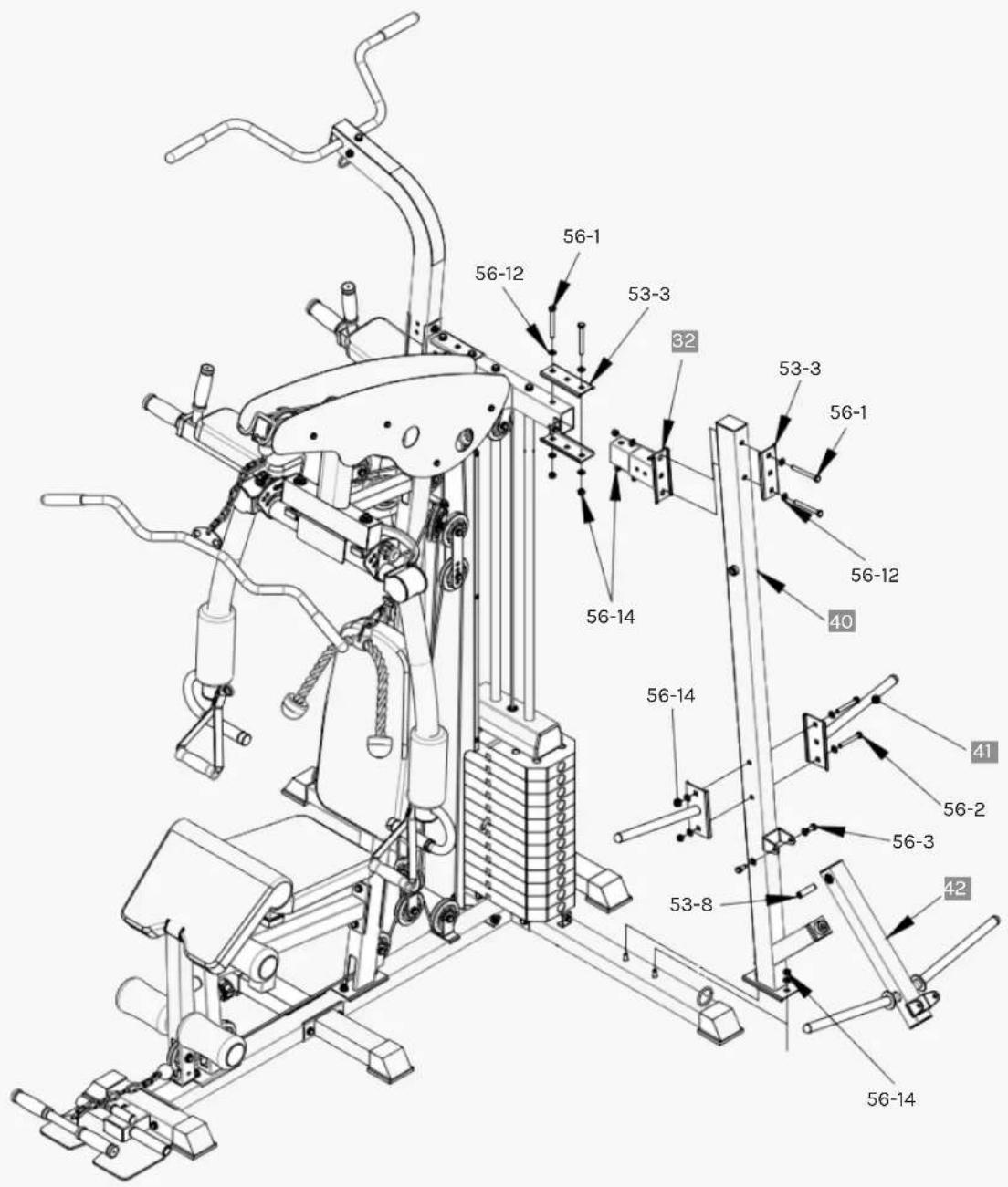
STEP 13
-
Install (#32) on (#13) as shown, and secure it with:
-
Plate (#53-3)
- Bolts (#56-1)
- Flat spacers (#56-12)
-
Nuts (#56-14)
-
Install (#40) to (#1) and tighten it with:
-
Flat washer (#56-12)
-
Nut (#56-14)
-
Installation diagram attaches two (#41) to (#40) and fixed with:
-
Bolts (#56-2)
- Flat spacers (#56-12)
-
Nuts (#56-14)
-
Finally place (#53-8) to (#42) and then (#42) to (#40), tightening both sides with:
-
Bolts (#56-3)
- Flat spacers (#56-12)
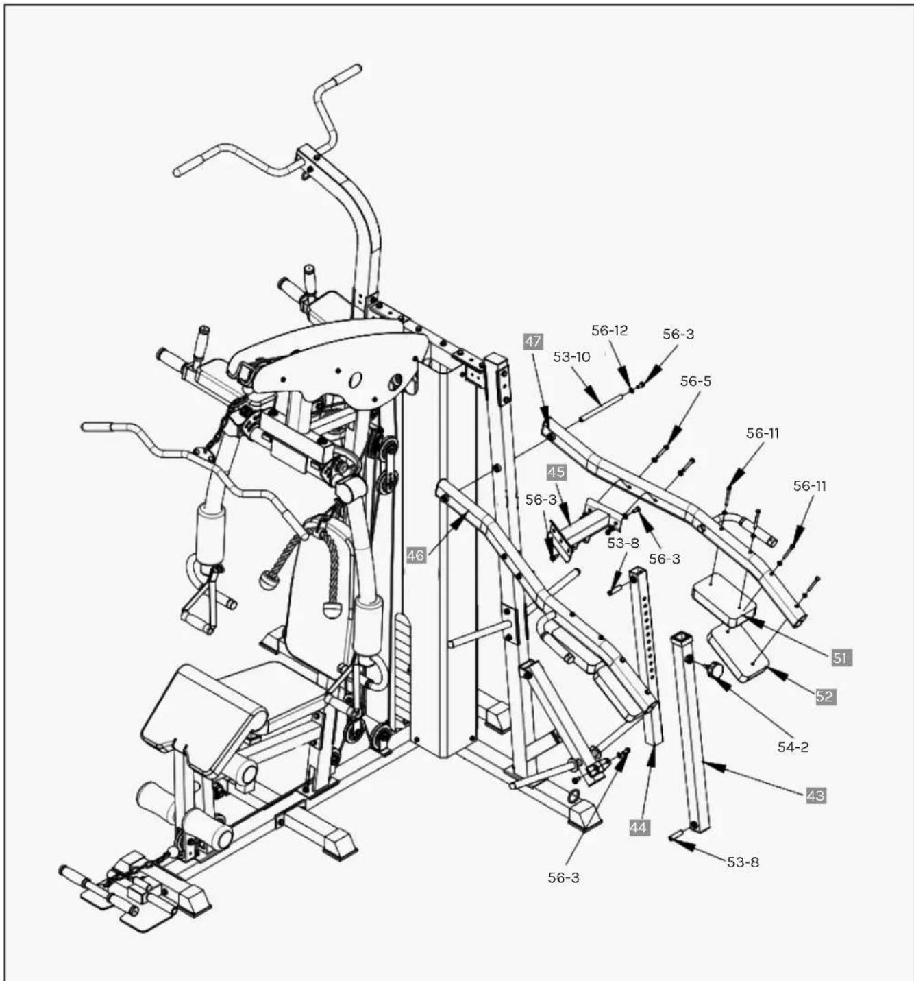
STEP 14
-
Install (#46) and (#47) to both sides of (#45), and secure them with:
-
Bolts (#56-5)
- Flat pads (#56-12)
-
Nuts (#56-14)
-
Place them onto (#40) and feed part (#53-10) though them then secure with:
-
Bolts (#56-3)
-
Flat pads (#56-12)
-
Install (#44) to (#43) and tighten with (#54-2).
-
Install (#53-8) to (#44), and then install (#44) to (#45) with:
-
Bolts (#56-3)
-
Flat spacers (#56-12).
-
Similarly, install (#53-8) to (#43), and then install (#43) to (#42) with:
-
Bolts (#56-3)
-
Flat spacers (#56-12)
-
Install (#51) and (#52) on (#46) and (#47) and be tightened with:
-
Bolts (#56-11)
- Flat spacers (#56-12)
Ensure to tighten all Nuts and Bolts with a wrench.
- Your device is now fully assembled.
- Check that all pulleys and wire ropes have been secured before proper correctly.
- In the first stage of use, the wire rope should be adjusted according to the actual situation.
V. MAINTENANCE INSTRUCTIONS
MAINTENANCE METHOD:
To extend the service life of the device, the parts must be lubricated on time. The product has been initially lubricated before leaving the factory, but lubrication is required between the guide rod and the weight plate over time.
NOTE: Silicon oil/spray is recommended for lubrication.
- Pulley and wire ropes should be regularly checked for signs of wear.
- Check and adjust the tension of the wire rope regularly.
- Check all moving parts regularly. If there is a damaged part, stop using the device immediately and contact the store.
- Ensure all bolts and nuts are fully fixed and re-tighten them when it is loose.
- Check the welding for cracks.
- Failure to perform routine maintenance may cause personal injury or equipment damage.
- Ensure any handle attachments are fully secured before use to prevent from injury.
VI. EXERCISE GUIDE
! PLEASE NOTE:
Before beginning any exercise program, consult your physician. This is important for individuals over the age of 45 or with pre-existing health problems.
The pulse sensors are not medical devices. Various factors, including the user's movement, may affect the accuracy of heart rate readings. The pulse sensors are intended only as an exercise aid in determining heart rate trends in general.
Exercising is great way to control your weight, improve your fitness and reduce the effect of aging and stress. The key to a healthy lifestyle is to make exercise a regular and enjoyable part of your everyday life.
The condition of your heart and lungs and how efficient they are in delivering oxygen via your blood to your muscles is an important factor to your fitness. Your muscles use this oxygen to provide enough energy for daily activity. This is called aerobic activity. When you are fit, your heart will not have to work so hard. It will pump a lot fewer times per minute, reducing the strain on your heart.
So as you can see, the fitter you are, the healthier and greater you will feel.
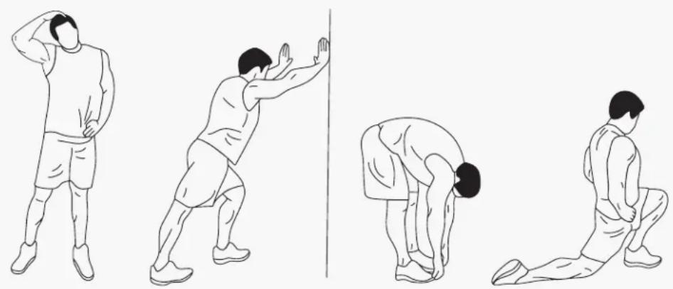
natural_image
Four sequential line drawings of a person performing a stretching or martial arts pose, no text or symbols present.WARM UP
Start each workout with 5 to 10 minutes of stretching and some light exercises. A proper warm-up increases your body temperature, heart rate and circulation in preparation for exercise. Ease into your exercise.
After warming up, increase the intensity to your desired exercise program. Be sure to maintain your intensity for maximum performance. Breathe regularly and deeply as you exercise.
COOL DOWN
Finish each workout with a light jog or walk for at least 1 minute. Then complete 5 to 10 minutes of stretching to cool down. This will increase the flexibility of your muscles and will help prevent post-exercise problems.
WORKOUT GUIDELINES

line
| AGE | HEART RATE | | --- | ---------- | | 40 | 120 | | 75 | 85 |This is how your pulse should behave during general fitness exercise. Remember to warm up and cool down for a few minutes.
VII. WARRANTY
AUSTRALIAN CONSUMER LAW
Many of our products come with a guarantee or warranty from the manufacturer. In addition, they come with guarantees that cannot be excluded under the Australian Consumer Law. You are entitled to a replacement or refund for a major failure and compensation for any other reasonably foreseeable loss or damage.
You are entitled to have the goods repaired or replaced if the goods fail to be of acceptable quality and the failure does not amount to a major failure. Full details of your consumer rights may be found at www.consumerlaw.gov.au.
Please visit our website to view our full warranty terms and conditions: http://www.lifespanfitness.com.au/warranty-repairs
WARRANTY AND SUPPORT
Any claim against this warranty must be made through your original place of purchase. Proof of purchase is required before a warranty claim may be processed.
If you have purchased this product from the Official Lifespan Fitness website, please visit https://lifespanfitness.com.au/warranty-form
For support outside of warranty, if you wish to purchase replacement parts or request a repair or service, please visit https://lifespanfitness.com.au/warranty-form and fill in our Repair/Service Request Form or Parts Purchase Form.
Scan this QR code with your device to go to lifespanfitness.com.au/warranty-form

CORTEX®
WWW.LIFESPANFITNESS.COM.AU


- GS7 Multi Station Home Gym
- TABLE OF CONTENTS
- IMPORTANT SAFETY INSTRUCTIONS
- WARNING: Read all instructions before using this machine.
- CARE INSTRUCTIONS
- PARTS LIST
- ASSEMBLY INSTRUCTIONS
- ! ATTENTION:
- STEP 1 - INSTRUCTIONS
- STEP 2
- STEP 3
- STEP 4
- STEP 5
- STEP 6
- STEP 7
- STEP 8
- STEP 9
- STEP 10
- STEP 11
- STEP 12
- STEP 13
- STEP 14
- MAINTENANCE INSTRUCTIONS
- MAINTENANCE METHOD:
- EXERCISE GUIDE
- ! PLEASE NOTE:
- WARM UP
- COOL DOWN
- WORKOUT GUIDELINES
- WARRANTY
- AUSTRALIAN CONSUMER LAW
- WARRANTY AND SUPPORT
Brand : CORTEX
Model : GS7
Category : Fitness Equipment