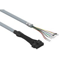
NEBM-L10G14-EH-10-Q7N-LE12 - Electrical cable Festo - Free user manual and instructions
Find the device manual for free NEBM-L10G14-EH-10-Q7N-LE12 Festo in PDF.


| Product Type | Sensor Connecting Cable |
| Model | NEBM-L10G14-EH-10-Q7N-LE12 |
| Brand | Festo |
| Cable Length | 10 m |
| Connector Type | M12, 4-pin, Straight |
| Thread Size | M14 x 1 |
| Wire Gauge | 0.34 mm² (AWG 22) |
| Rated Voltage | 250 V AC/DC |
| Rated Current | 4 A |
| Protection Class | IP67 (when mated) |
| Operating Temperature | -25 °C to +80 °C |
| Cable Jacket Material | PUR (Polyurethane) |
| Shielding | Unshielded |
| Key Functions | Reliable signal transmission for sensors and actuators |
| Certifications | CE, UL, RoHS |
| Maintenance | Periodic visual inspection for damage; keep dry and clean |
| Cleaning | Wipe with a dry cloth; avoid solvents |
| Safety Notes | Disconnect power before handling; do not exceed ratings |
| Spare Parts / Repairability | Non-repairable; replace entire cable if defective |
Frequently Asked Questions - NEBM-L10G14-EH-10-Q7N-LE12 Festo
User questions about NEBM-L10G14-EH-10-Q7N-LE12 Festo
0 question about this device. Answer the ones you know or ask your own.
Ask a new question about this device
Download the instructions for your Electrical cable in PDF format for free! Find your manual NEBM-L10G14-EH-10-Q7N-LE12 - Festo and take your electronic device back in hand. On this page are published all the documents necessary for the use of your device. NEBM-L10G14-EH-10-Q7N-LE12 by Festo.
USER MANUAL NEBM-L10G14-EH-10-Q7N-LE12 Festo
natural_image
Illustration of a USB cable connector with multiple leads (no text or symbols)FESTO
Festo SE & Co. KG
Ruiter Straße 82
73734 Esslingen
Germany
+49 711 347-0
www.festo.com
Assembly instructions
8156480
2024-03
[8156482]
8156480
Original instructions
© 2024 all rights reserved to Festo SE & Co. KG
1 Applicable documents
All available documents for the product → www.festo.com/sp.
2 Safety
2.1 Safety instructions
- Before working on the product: Switch off the power supply, ensure that it is off and secure it against being switched on again.
2.2 Intended use
The motor cable connects the stepper motor EMMB-ST with the servo drive CMMT-ST.
2.3 Training of qualified personnel
Work on the product may only be carried out by qualified personnel who can evaluate the work and detect dangers. The qualified personnel are trained in electrical engineering.
3 Additional information
- Contact the regional Festo contact if you have technical problems
→ www.festo.com.
- Accessories → www.festo.com/catalogue.
4 Structure
4.1 Product design
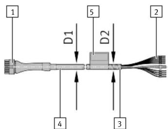
1 Hybrid socket L10
2 Wire end (12x)
3 Shielded connection
4 Cable
5 Contact assignment identification
Fig. 1: Product design
4.2 Contact assignment for motor and brake
| Electrical connection 1Field device side | Signal Electrical connection 2Controller side X6 | ||
| [1] Hybrid socket [2] Wire ends | 1) | ||
| 1311975311412108642 | 1 Phase A RD | ||
| 2 Phase A/ BN | |||
| 3 BR+ GN WH | |||
| 4 BR- BU WH | |||
| 5 Shielding – | |||
| 6 Not assigned – | |||
| 13 Phase B BK | |||
| 14 Phase B/ WH | |||
1) Colour code in accordance with IEC 60757:2021-06
Tab. 1: Contact assignment for motor and brake
4.3 Encoder contact assignment
| Electrical connection 1Field device side | Signal Electrical connection 2Controller side X2 | ||
| [1] Hybrid socket [2] Wire ends | |||
| 7 SLO+ | VT | ||
| 8 SLO- | YE | ||
| 9 MA+ | GY | ||
| 10 MA-PK | |||
| 11 +5 V | RD | ||
| 12 GND (0 V) | BU | ||
1) Colour code in accordance with IEC 60757:2021-06
Tab. 2: Encoder contact assignment
5 Mounting
5.1 Mounting electrical connection 1
- Align the hybrid socket [1].
- Plug the hybrid socket [1] into the connection and click it into place.
5.2 Strain relief for electrical connection 1
• Fix the cable sheath in the section before the hybrid socket.
No strain on the hybrid socket.
5.3 Mounting electrical connection 2
- Attach the shield connection [3] to the servo drive with the shield clamp
→ Servo drive operating instructions CMMT-ST. - Connect the wire ends [2] in accordance with the contact assignment. Note the contact assignment identification [5].
5.4 Strain relief for electrical connection 2
• Fix the cable sheath in the area in front of the wire ends.
No strain on the wires.
5.5 Wiring
| Characteristics | Cable characteristics | Wiring |
| -E | Suitability for energy chains | In energy chain or flexible |
Tab. 3: Wiring
5.6 Mounting in energy chain
- Lay out the energy chain lengthways.
- Place the cables in the energy chain without twisting them.
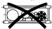
- Separate cables from each other using separators/drilled holes.
- Do not bind cables in bundles.
- Maintain space X. X > 10% of the cable diameter D. With the energy chain hanging vertically: increase the space X.


-
Align the energy chain in the working position:
-
Make sure that the radius is greater than the bending radius R of the cables.
–The cables can move freely in the bending radius KR of the energy chain.


The cable movement is not forced by the energy chain.
- Mount the energy chain corresponding instruction manual.
-
Fasten the cables:
-
for short energy chains with a length < 1 m at both ends of the energy chain
-
for long sliding energy chains with a length >1 m at the driver end only
-
Do not move cables all the way to the fastening point.


natural_image
3D wireframe model of a mechanical component with curved and straight sections, labeled 'A' at the base (no text or symbols on the structure itself)The mounting space A between the fastening point and bending movement is maintained.
NOTICE
Damage to cables if the chain breaks.
- Replace cables after a chain break.
NOTICE
Malfunction and material damage due to vertically suspended cables.
The cables stretch.
- Regularly check the length of the cables.
- Readjust the cables if required.
6 Technical data
| NEBM-L10G14-EH-...-LE12 -Q6(N) | -Q7(N) -Q9(N) | ||
| Certificates, declaration of conformity | → www.festo.com/sp | ||
| Cable characteristic Suitability for energy chains | |||
| Cable function 3x motor cable | |||
| Cable composition [mm2] 4x0.5 + 2x0.5 | + 6x0.15 | 4x0.75 + 2x0.5 + 6x0.15 | 4x1.5 + 2x0.5 + 6x0.15 |
| Shielding Shielded | |||
| Cable diameter D1 [mm] 10.5 10.8 | |||
| Diameter of shield sleeve D2 [mm] Approx. 12 | 5 | ||
| Mounting space A [mm] ≥ 250 | |||
| Current rating at 40 °C [A] | 7.6 | 11.7 | 17.8 |
| Surge resistance [kV] | 1.5 | ||
| Operating voltage range | |||
| DC UB [V] | 0 ... 48 | ||
| Bending radius | |||
| Fixed cable installation R [mm] | ≥ 42 | ≥ 43.2 | |
| Flexible cable installation R [mm] | ≥ 78.75 | ≥ 81 | |
| Ambient temperature | |||
| Fixed cable installation [°C] | -40 ... +90 | ||
| Flexible cable installation [°C] | -25 ... +80 | ||
| Material | |||
| Cable sheath | TPE-U(PUR) | ||
| Insulating sheath | PP | ||
| Electrical connection 1 | |||
| Function | Field device side | ||
| Connection type | Hybrid socket | ||
| Connection technology | Plug pattern L10 | ||
| Number of pins/cores | 14 | ||
| Assigned pins/cores | 13 | ||
| Type of mounting | Snap-locking | ||
| Degree of protection In assembled state | IP20 | ||
| Electrical connection 2 | |||
| Function | Controller side | ||
| Connection type | Cable | ||
| Connection technology | Open end | ||
| Number of pins/cores | 12 | ||
| Assigned pins/cores | 12 | ||
| Wire ends | Wire ferrule | ||
| Degree of protection In assembled state | IP20 | ||
Tab. 4: Technical data
- FESTO
- Applicable documents
- Safety
- Safety instructions
- Intended use
- Training of qualified personnel
- Additional information
- Structure
- Mounting
- Mounting electrical connection 1
- Strain relief for electrical connection 1
- Mounting electrical connection 2
- Strain relief for electrical connection 2
- Mounting in energy chain
- NOTICE
- Damage to cables if the chain breaks.
- Malfunction and material damage due to vertically suspended cables.
Brand : Festo
Model : NEBM-L10G14-EH-10-Q7N-LE12
Category : Electrical cable