
SHP M ECO R5 - Water heater SIME - Free user manual and instructions
Find the device manual for free SHP M ECO R5 SIME in PDF.


| Product Type | Controller for Inverter Air/Water Heat Pump and Chiller |
| Compatible Models | SHP M ECO 006A, 008A, 010, 010T, 012, 012T, 014, 014T, 016, 016T |
| Power Supply | 230V~ 50Hz |
| Controller Outputs | 230Vac, 50Hz, 2A (AC1) per output |
| Main Functions | Heating, Cooling, Domestic Hot Water (DHW), Defrost, Antifreeze, Integration Heaters, Boiler Management |
| User Interface | Keypad with MODE/ESC, PRG, UP/DOWN keys; LED indicators for modes, alarms, defrost, compressor, pump, DHW |
| Setpoint Range (Heating) | 25°C to 60°C (default 45°C) |
| Setpoint Range (Cooling) | 5°C to 25°C (default 7°C) |
| DHW Setpoint Range | 25°C to 60°C (default 48°C) |
| Communication | Modbus RTU (RS485), USB port for firmware/parameter update |
| Dynamic Setpoint | Climatic compensation based on outdoor temperature or 0-10V/ratiometric input |
| Circulator Modes | Continuous, on-demand, periodic activation; proportional speed control |
| Safety Features | High/low pressure alarms, flow switch, antifreeze, overtemperature, inverter protections |
| Defrost Cycle | Automatic in heating mode; adjustable parameters |
| Integration Options | Electric heaters, boiler, solar thermal (with optional GI module), secondary circulator |
| Optional Accessories | Hi-T2 remote touch screen, GI module for mixer valve and solar integration, KA antifreeze heater kit |
| Compliance | Designed for use by trained operators; WEEE directive 2012/19/EU |
| Maintenance | Cleaning and maintenance by qualified personnel only; disconnect power before servicing |
| Manual Languages | Original manual in English; translations available on request |
Frequently Asked Questions - SHP M ECO R5 SIME
User questions about SHP M ECO R5 SIME
0 question about this device. Answer the ones you know or ask your own.
Ask a new question about this device
Download the instructions for your Water heater in PDF format for free! Find your manual SHP M ECO R5 - SIME and take your electronic device back in hand. On this page are published all the documents necessary for the use of your device. SHP M ECO R5 by SIME.
USER MANUAL SHP M ECO R5 SIME
Chiller and Inverter Air/Water heat pumps with axial fans
Controller Manual
Model
SHP M ECO 006A
SHP M ECO 008A
SHP M ECO 010
SHP M ECO 010T
SHP M ECO 012
SHP M ECO 012T
SHP M ECO 014
SHP M ECO 014T
SHP M ECO 016
SHP M ECO 016T
EN

Fonderie SIME S.p.A.
cod. 7500375 - R08
| 08 10-2022 M.S. A.B. Parameter visibility alignment, insertion of GI module chapters | |||
| 07 05-2022 E.G. A.B. Update sizes 006A, 008A, elimination of GI module chapters | |||
| 06 12-2021 M.S. A.B. Elimination cap. 9.1 | |||
| 05 03-2021 A.B. A.B. Update chap. 8-9.1-10.15-10.16-10.17-14.3 | |||
| 04 09-2020 M.S. A.B. Compressor shutdown activation logic update | |||
| 03 06-2020 M.S. A.B. Adding flowmeter chapter | |||
| 02 03-2020 M.S./K.G. A.B. Modification of the chapters 6, 9,11, 12 and 15 | |||
| 01 10-2019 M.S. A.B. Updating | |||
| Rev | Data | Redatto | Approvato |
| Catalogo / Catalogue / Katalog / Catalogue | Serie / Series / Serie / Serie / Série | ||
| MCO0110L8500-08 | CONTROLLER FOR AIR/WATER INVERTER-CONTROLLED CHILLERS AND HEAT PUMPS WITH AXIAL FANS | ||
The electrical and electronic products and any waste should not be disposed of with normal household waste, but disposed of according to WEEE law in accordance with the directive 2012/19/EU, inquiring thereof at the place of residence or with the retailer in the case where the product is replaced with a similar one.

INDEX
1.HOW TO KEEP THE MANUAL 6
1.1 GRAPHIC SYMBOLS USED IN THE MANUAL 6
- PERMITTED USED 6
3.GENERAL SAFETY GUIDELINES 6
3.1 PERSONAL PROTECTIVE EQUIPMENT....6
3.2 WORKERS' HEALTH AND SAFETY 6
4.PURPOSE AND CONTENTS OF THE MANUAL 8
5.USER INTERFACE - CONTROLLER....9
5.1 MENU....9
5.2 SETPOINT MENU....9
5.3 PASSWORD MENU [PSS]....10
5.4 PROBES MENU [tP] 10
5.5 ALARMS MENU [Err] 10
5.6 DIGITAL INPUTS MENU [Id]....10
5.7 PARAMETERS MENU [Par]....10
5.8 OPERATING HOURS MENU [oHr]....11
5.9 MENU VERSIONE FIRMWARE [Fir]......11
5.10 LOG MENU [HiSt].... 11
5.11 USB MENU [USB] 11
5.11.1 FIRMWARE UPDATE [UPDF]......11
5.11.2 PARAMETERS UPDATE [UPPA] 11
5.12 DISPLAY....11
5.12.1 LED 12
5.13 TERMINAL BLOCK 12
- EDITING DYNAMIC SET-POINT ...... 13
6.1 SETTINGS FOR STANDARD CLIMATIC CURVES 13
6.2 EDIT THE SET-POINT FROM 0-10V INPUT OR FROM RATIOMETRIC INPUT .....14
7.CIRCULATOR....14
7.1 CONTINUOUS OPERATION [P03=0] - Default 15
7.2 OPERATION ON CALL BY TEMPERATURE CONTROLLER [P03=1]....15
7.3 OPERATING ON CALL BY TEMPERATURE CONTROLLER WITH PERIODIC ACTIVATION....15
7.4 OPERATION WITH HEATER ACTIVE 15
7.5 PROPORTIONAL REGULATION OF THE CIRCULATOR....15
7.6 SYSTEM VENTING 16
8.COMPRESSOR OR ACTIVATION LOGIC 16
8.1 REGULATION IN COOLING MODE 16
8.2 REGULATION IN HEAT MODE....16
9.DISSIPATION FAN CONTROL....17
10.CONTROLLER FUNCTIONS 17
10.1 ANTIFREEZE PROTECTION HEATERS (IF KA ACCESSORY IS AVAILABLE)......17
10.2 ENABLING DOMESTIC HOT WATER PRODUCTION....17
10.2.1 MEMORISING THE PROBE IN HEATING MODE 18
10.2.2 HEATING MODE ON DHW STORAGE TANK....18
10.2.3 INSUFFICIENT HEAT EXCHANGE IN A DHW SYSTEM 18
10.3 REMOTE-CONTROLLED FUNCTIONS....18
10.3.1 ON/OFF....18
10.3.2 SUMMER/WINTER MODE CHANGE 19
10.3.3 DHW CALL FROM DIGITAL INPUT....19
10.4 SYSTEM WATER REMOTE PROBE....19
10.5 AUXILIARY HEATERS 19
10.5.1 PLANT HEATER....19
10.5.2 PLANT HEATER IN DEFROST....20
10.5.3 DHW HEATER 20
10.5.4 SINGLE PLANT/DHW INTEGRATION HEATER....20
10.6 INTEGRATION HEATER SELECTION MODE....20
10.7 CIRCULATOR MANAGEMENT WITH HEATER ON....20
10.8 BOILER ENABLING 20
10.9 ACTIVATION OF INTEGRATION HEATERS AND BOILER IN JOINT OPERATION AND IN SUBSTITUTION OF HEAT PUMP COMPRESSOR....21
10.9.1 OPERATION IN HEAT PUMP MODE 21
10.9.2 JOINT OPERATION (I BRACKET) 21
10.9.3 JOINT OPERATION (II BRACKET) 21
10.9.4 OPERATION IN SUBSTITUTION 22
10.10 OPERATING BRACKETS - ACTIVATION OF INTEGRATION HEATERS (PLANT REMOTE WATER PROBE NOT ENABLED) 22
10.10.1 AUXILIARY SYSTEMS OFFSET MANAGEMENT 25
10.11 WARNINGS....25
10.11.1 PLANT SEASON 25
10.11.2 ALARM 25
10.11.3 MACHINE BLOCK....25
10.11.4 DEFROST 25
10.12 DEFROST CYCLE 25
10.13 COMPRESSOR CRANKCASE HEATER....26
10.14 DOUBLE SET-POINT 26
10.15 MINIMUM HZ FUNCTIONALITY....26
10.16 MAXIMUM HZ FUNCTIONALITY 26
10.17 FLOWMETER 26
11.FUNCTIONS THAT CAN BE ACTIVATED WITH HI-T2 ACCESSORY (OPTIONAL) .....27
12.FUNCTIONS THAT CAN BE ACTIVATED WITH GI MODULE (OPTIONAL)....27
12.1 I/O RESOURCES OF THE CONTROLLER....27
12.2 MANAGEMENT OF SECONDARY CIRCULATOR/BOOSTER PUMP (WITH ROOM THERMOSTAT) 28
12.3 MIXER VALVE MANAGEMENT 28
12.3.1 DETERMINATION OF SETPOINT 28
12.3.2 RADIANT PANELS CIRCUIT PUMP 28
12.3.3 MIXER VALVE....28
12.4 SOLAR INTEGRATION MANAGEMENT 29
12.4.1 ACTIVATION OF SOLAR CIRCULATOR 29
12.4.2 COLLECTOR PROTECTION 29
12.4.3 COLLECTOR OVERTEMPERATURE ALARM 29
12.4.4 DHW OVERTEMPERATURE ALARM 29
12.4.5 SOLAR EXHAUST VALVE 29
12.4.6 DISSIPATION OF SOLAR TANK HEAT 29
12.4.7 ANTIFREEZE....29
13.TABLES OF PERMITTED SETUPS FOR USER AND INSTALLER 30
14.ALARMS....33
14.1 [E006] FLOW SWITCH 34
14.2 [E018] HIGH-TEMPERATURE 34
14.3 [E020] INVERTER TRASDUCTORS....34
14.4 [E005] ANTIFREEZE 34
14.5 [E611÷E681] PROBE ALARMS 34
14.6 [E801] TIMEOUT INVERTER....34
14.7 [E851 ÷ E971] INVERTER 34
14.8 [E00] REMOTE ON/OFF (WARNING) 34
14.9 [E001] HIGH-PRESSURE 34
14.10 [E002] LOW-PRESSURE 34
14.11 [E008] DRIVER LIMITATION 34
14.12 [E041] 4-WAY VALVE....34
14.13 POWER FAILURE 35
14.14 UTILITIES BLOCK ALARM TABLE 35
15.MODBUS VARIABLES 35
1. HOW TO KEEP THE MANUAL
The manual has to always be kept together with the unit it refers to. It has to be stored in a safe place, away from dust and moisture. It must be accessible to all users who shall consult it any time they are in doubt on how to operate the equipment.
The company reserves the right to modify its products and related manuals without necessarily updating previous versions of the reference material. We also decline any responsibility for possible inaccuracies in the manual if due to printing or transcription errors.
The customer shall store any updated copy of the manual or parts of it delivered by the manufacturer as an attachment to this manual.
The company is available to give any detailed information about this manual and to give information regarding the use and the maintenance of its own units.
1.1 GRAPHIC SYMBOLS USED IN THE MANUAL

Indicates prohibited operations.

Indicates operations that can be dangerous for people and/or disrupt the correct operation of the unit.

Hazardous electrical voltage - Electrocution hazard

Indicates important information that the operator has to follow in order to guarantee the correct operation of the unit in complete safety. Also indicates some general information.
2. PERMITTED USED
- The company excludes any contractual and extra contractual liability for damage caused to persons, animals or objects, by incorrect installation, setting and maintenance, improper use of the equipment, and the partial or superficial reading of the information contained in this manual.
- These units are built for the heating and/or cooling of water. Any other use not expressly authorised by the manufacturer is considered improper and therefore not allowed.
- All the work must be executed by skilled and qualified personnel, competent on the existing regulations in country of installation.
- This appliance is intended to be used by expert or trained operators in shops, light industry and in factories, or for commercial use by non-expert personnel.
- The appliance may be used by children at least 8 years old and by persons with reduced physical, sensory or mental capabilities or without experience or the necessary knowledge as long as they are supervised or after they themselves have received instructions on the safe use of the appliance and understand the relevant dangers. Children must not play with the appliance. The cleaning and maintenance which the user is expected to carry out on the unit cannot be done by children without supervision.
3. GENERAL SAFETY GUIDELINES
Before starting any type of operation on the unit, every user and operator must have perfect knowledge of operation of the machine and of its controls and have read and understood all of the information in this manual and in the user-installer manual.
3.1 PERSONAL PROTECTIVE EQUIPMENT
Refer to the user-installer manual which accompanies the unit.
3.2 WORKERS' HEALTH AND SAFETY
Refer to the user-installer manual which accompanies the unit.
 | IT IS PROHIBITED: |
| To remove and/or to tamper with any safety device. | |
| For unauthorised personnel to access the electric panel. | |
| To work on live systems. | |
| To touch the systems if not authorised to do so | |
| To allow children or unassisted disabled persons to use the appliance. | |
| To touch the appliance when barefoot or parts of the body are wet or damp. | |
| To perform any cleaning operation when the master switch is 'ON'. | |
| To pull, detach or twist the appliance's electric cables. | |
| To step on, sit down on and/or place any type of object on the appliance. | |
| To spray or pour water directly on the unit. | |
| To dispose of, abandon or leave within reach of children packaging materials (cardboard, staples, plastic bags, etc.) as they may represent a hazard for the environment and one's life. | |
| To tamper with or replace parts of the unit without the specific consent of the manufacturer. The manufacturer shall have no responsibility whatsoever in case of unauthorised operations. | |
 | CAUTION: |
| Refer to the user-installer manual which accompanies the unit before proceeding. | |
| All the operation described below must be done by QUALIFIED PERSONNEL ONLY. | |
| The electrical wiring to the terminal blocks has to be done only by qualified personnel. | |
| Any routine and/or extraordinary maintenance operation must be carried out with the machine stopped and disconnected. | |
| Do not place your hands or introduce screwdrivers, spanners or any other tools on moving parts. | |
| The machine operator and maintenance personnel must receive suitable training for the performance of their tasks in safety. | |
| Only authorised personnel are allowed to have access to the electric panel. | |
| Operators must know how to use personal protective equipment and the accident-prevention rules of national and international laws and regulations. | |
| The operator's workplace has to be kept clean, tidy and clear of objects that may hinder free movement. Appropriate lighting of the work place shall be provided so as to allow the operator to carry out the required operations safely. Poor or excessive lighting can cause risks. | |
| Ensure that work places are always adequately ventilated and that the extraction systems are working, in good condition and in compliance with the requirements of the laws in force. | |
| Not all of the configurations described can be activated and/or modified at the same time. | |
| Values other than the default values can jeopardise proper operation of the unit. If in doubt on which value to set, contact our headquarters. | |
| The company excludes any contractual and extra contractual liability for damage caused to persons, animals or objects, by incorrect installation, setting and maintenance, improper use of the equipment, and the partial or superficial reading of the information contained in this manual.The power supply has to respect the limits shown on the unit's technical label: failing this, the warranty will terminate immediately. Before beginning any type of operation, make sure that power is disconnected. | |
 | |
| Connect the conductors in order: phase, neutral and earth. | |
| Dimensioning of the power cables must take into consideration the TECHNICAL DATA provided in the user-installer manual accompanying the unit. Also consider any auxiliary heating devices. | |
| Effective earthing is mandatory; the manufacturer is not responsible for damage caused in case of lack thereof. | |
| When undergoing maintenance, the unit must be disconnected from the power supply, and it must be unplugged in such a way that the operator can verify from wherever he accesses that the plug remains disconnected. | |
| Use cables that meet the regulations in force in the different countries. | |
| After the unit has been running for 10 minutes, make sure that the screws on the power terminal block remain secured. | |
 | Install upstream of each unit a suitable QF protective device and power disconnector, with delayed characteristic curve, with at least 3 mm contact opening and adequate breaking capacity and residual current protection. The size of the circuit breaker must comply with absorption of the unit. See the TECHNICAL DATA in the user-installer manual which accompanies the unit. Also consider any auxiliary heating devices. |
| Before performing any operations on the electric panel, IT IS MANDATORY: | |
| To switch off the unit from the control panel ("OFF" displayed). | |
| To place the general residual current device QF at "OFF". | |
| To wait 15 seconds before accessing the electric panel. | |
| To check the grounding before performing any operation. | |
| To remain well isolated from the ground, with dry hands and feet, or using insulated platforms and gloves. | |
| To keep foreign materials away from the systems. | |
4. PURPOSE AND CONTENTS OF THE MANUAL
The manual is intended to provide the essential information to configure the controller of the units.
It is addressed to the installer and operators of the appliance and it enables them to use the equipment efficiently, even if they do not have any previous specific knowledge of it.
Not all of the functions described can be activated and/or selected at the same time. Contact our headquarters for further information.
The manual describes the machine at the moment it was sold. It must therefore be considered adequate with respect to the state-of-the-art in terms of potentiality, ergonomics, safety and functionality.
The company also performs technological upgrades and does not consider itself obliged to update the manuals of previous machine versions which could even be incompatible. Therefore make sure to use the supplied manual for the installed unit. Contact our headquarters in case of updates or doubts.
The user is recommended to follow the instructions contained in this booklet, especially those concerning safety and routine maintenance.
5. USER INTERFACE - CONTROLLER

| MODEESC | Select the operating mode and manually reset any alarms.Each time you press the key you have the following sequence:OFF -> COOL -> HEAT -> OFFIf DHW is enabled, the sequence is the following:OFF -> COOL -> COOL+SAN -> HEAT -> HEAT+SAN -> OFFWhile setting the parameters, this key has the function of sending BACK by one level. |
| PRG | Grants access to the parameter setting menu and allows you to set the summer, winter and sanitary setpoint. |
 | UP key. In the parameter setting mode, it allows you to move to a higher menu or to increase the parameter value when in “edit” mode. |
| DOWN key. In the parameter setting mode, it allows you to move to a lower menu or to decrease the parameter value when in “edit” mode. |
5.1 MENU
The following are the main features for navigating the menus, especially describing functions which are not obvious. The main menu has the following items:
| MENU LABEL PASSWORD LEVEL OTHER CONDITIONS | |||
| Setpoint Set User Not accessible if connected to Hi-T2 | |||
| Probes tP Installer --- | |||
| Alarms Err User | Only if active alarms | ||
| Digital input | Id | Installer | --- |
| Parameters | Par | Installer | --- |
| Password | PSS | User | --- |
| Hours of operations | oHr | Installer | --- |
| USB | USb | Installer | Only with pen drive with relevant update files |
| Versione Firmware | Fir | Installer | Version, Revision and Sub |
| Alarm log | Hist | Installer | Only if the log contains data |
The PSS menu is accessed to enter the service password and to enable access with a higher user permission. When you have exited the menus, the password must be entered once again to re-enter.
5.2 SETPOINT MENU
The various setpoints can be viewed and edited.
| SETPOINT | DESCRIPTION | UNIT DEFAULT | RANGE | |
| Coo | First Summer setpoint | °C | 7.0 | 5 ÷ Co2 |
| Hea | First Winter setpoint | °C | 45.0 | 25 ÷ 60 |
| *San | Sanitary setpoint | °C | 48.0 | 25 ÷ 60 |
| Coo2 | Second Summer setpoint | °C | 18.0 | Coo ÷ 25 |
| Hea2 | Second Winter setpoint | °C | 35.0 | 25 ÷ Hea |
| San2 | Second Sanitary setpoint | °C | 35.0 | 25 ÷ Hea |
| **rCoo | Mixing valve Summer setpoint | °C | 15.0 | 0.0 ÷ 80 |
| SETPOINT DESCRIPTION UNIT DEFAULT RANGE | |||
| **rHEA Mixing valve Winter setpoint °C 30.0 0.0 ÷ 80 |
(*) If the DHW function is enabled, see par. 10.2
(**) If Gi accessory is included, access is only possible with installer password.
5.3 PASSWORD MENU [PSS]
Enter the password according to the desired access level. Confirming the value automatically activates the access level and the items of the menus enabled at that level will appear.
5.4 PROBES MENU [tP]
The value of the different probes appears. The number of visible probes depends on whether or not the I/O expansion modules are present. Particular situations:
- Err = probe faulty
- --- = probe not used (no function associated to that probe)
Entering the "tP" analogue inputs menu with the installer password allows you to read the values of the probes present:
| tP DESCRIPTION Unit of measurement | ||
| t01 Inlet water temperature °C | ||
| t02 | Outlet water temperature | °C |
| t03 | Compressor intake temperature | °C |
| t04 | Compressor discharge temperature | °C |
| t05 | Outdoor air temperature | °C |
| *t06 | DHW probe temperature | °C |
| *t07 | Plant remote probe temperature | °C |
| t09 | Low pressure | (bar) |
| t10 | High pressure | (bar) |
| t11 | Water flow | (l/min) |
| **t15 | Mixer probe temperature | °C |
| **t16 | Solar storage tank probe temperature | °C |
| **t17 | Solar collector probe temperature | °C |
(*) If enabled
(**) If Gi accessory present and enabled.
Please note that the menu is password-protected.
5.5 ALARMS MENU [Err]
This menu is only displayed if there are triggered alarms. All of the active alarms can be seen.
5.6 DIGITAL INPUTS MENU [Id]
The status of the digital inputs are displayed:
0=deactivated
1=active
----=input not configured
Please note that the menu is password-protected.
5.7 PARAMETERS MENU [Par]
The parameters are gathered into groups. Each group is identified by a three-digit code, while the index of each parameter is preceded by a letter.
| DESCRIPTION | IDENTIFICATION CODE OF THE GROUP | PARAMETER INDEX | VISIBILITY |
| Configuration | CnF | H01- | INSTALLER |
| Compressor | CP | C01- | INSTALLER |
| Alarms | ALL | A01- | INSTALLER |
| Regulation | rE | b01- | INSTALLER |
| Pump | PUP | P01- | INSTALLER |
| Electric heaters | Fro | r01- | INSTALLER |
| Defrost | dFr | d01- | INSTALLER |
| Hz min / max | LbH | L0- | INSTALLER |
| *Solar | SUn | S01- | INSTALLER |
| DESCRIPTION | IDENTIFICATION CODE OF THE GROUP | PARAMETER INDEX VISIBILITY |
| *Mixer valve rAD i01- | INSTALLER |
(*) To configure if Gi module present
To access the installer parameters: PRG -> PSS -> PRG -> (enter Service password) ->PRG ->PAr -> PRG
Please note that the menu is password-protected.
5.8 OPERATING HOURS MENU [oHr]
This displays the operating hours of the compressor (oH1) and of the circulator (oHP1)
Pressing ESC for 3 seconds resets the currently displayed count.
Please note that the menu is password-protected.
5.9 MENU VERSIONE FIRMWARE [Fir]
Firmware Version (uEr), Firmware revision (rEu) and sub (SUb) can be displayed.
Please note that the menu is password-protected.
5.10 LOG MENU [HiSt]
It is only displayed if there are triggered alarms.
5.11 USB MENU [USB]
Only visible with pen drive with related files
The following are the functions available by using the USB pen drive connected the board.
Please note that the menu is password-protected.
![SIME SHP M ECO R5 - USB MENU [USB] - 1](/content/2026/05/1045894/images/ba3fbdd4b4ee3a61d85fe6562f82aec8f73793dd40dc9fb05e36bfbe186c7a87.jpg)
CAUTION
All the operations with INSTALLER visibility must be carried out by QUALIFIED PERSONNEL.
The company excludes any contractual and extra contractual liability for damage caused to persons, animals or objects, by incorrect installation, setting and maintenance, improper use of the equipment, and the partial or superficial reading of the information contained in this manual.
5.11.1 FIRMWARE UPDATE [UPdF]
In case of firmware update, it is possible to make the upgrade by means of a USB pen drive, using the USB port in the controller. For the upgrade:
- Copy the upgrade files in the root directory of a USB pen-drive;
- Set the unit in Standby and shut it down by placing the master switch at OFF;
- Insert the pen-drive into the USB port of the controller;
- Power on the unit, placing the master switch at ON;
- Access the parameters PRG -> PSS -> PRG -> (enter Service password) -> PRG -> USB -> UPdF -> PRG. Selecting this item starts the automatic firmware upgrade procedure. The display shows a count indicating the transferred Kbytes. At the end of the procedure, "boot" appears on the screen and 4 LEDs light up in sequence;
- When the installation is complete, the board returns to normal operation and the machine is ready to be activated;
- Switch off the unit, placing the master switch at OFF;
- Remove the pen drive from the USB port;
- Power on the unit, placing the master switch at ON.
5.11.2 PARAMETERS UPDATE [UPPA]
In case of parameters update, it is possible to make the upgrade by means of a USB pen drive, using the USB port in the controller.
For the upgrade:
- Copy the upgrade parameter files in the root directory of a USB pen-drive;
- Set the unit in Standby and shut it down by placing the master switch at OFF;
- Insert the pen-drive into the USB port of the controller;
- Power on the unit, placing the master switch at ON;
- Access the parameters PRG -> PSS -> PRG -> (enter service password) -> PRG -> USB -> UPPA -> PRG. Selecting this item starts the automatic parameters upgrade procedure. The display shows a count indicating the transferred Kbytes;
- When the count is over, switch off the unit, placing the master switch at OFF;
- Remove the pen drive from the USB port;
- Power on the unit, placing the master switch at ON.
5.12 DISPLAY
In standard operation, the display shows the water outlet temperature in tenths of Celsius degrees or the alarm code if at least one is active. If several alarms are triggered, the first one is displayed while the second one will be displayed as soon as the first one is reset. In menu mode, the display depends on the current position.
5.12.1 LED
 | Cooling mode LED • LED ON if unit is in cooling mode. | |
 | Heating mode LED • LED ON if unit is in heating mode. | |
 | Pump LED • LED ON if pump running. | |
 | Alarm LED • LED ON if an alarm is triggered. | |
 | Defrost LED | • ON if defrosting enabled• OFF if defrosting disabled or finished• FLASHING if defrosting time interval count in progress |
 | Compressor LED | • ON if the compressor is running• OFF if the compressor is off• FLASHING if pending the timed compressor start |
 | Domestic hot water LED | • ON if sanitary mode enabled• OFF if sanitary mode disabled• FLASHING if DHW production in progress (sanitary valve on) |
 | Antifreeze heater LED • LED ON if antifreeze heater on. |
5.13 TERMINAL BLOCK
The following is the list of I/O (inputs and outputs) that can be set to activate the functions of the controller.
| Resource Parameter | Terminal block X | Factory configuration | Description | ||
| Default value | Function | ||||
| ST 6 H17 17.1 / | 17.2 0 Not set | Analogue input configurable with an NTC-10KΩ probe at 25°C β 3435 | |||
| ST 7 H18 19.1 / | 19.2 0 Not set | Analogue input configurable with an NTC-10KΩ probe at 25°C β 3435 | |||
| ST 11 H22 | 22.1 (gnd)22.2 (under-voltage) | 0 Not set 0-10Vdc under-voltage input | |||
| ID 2 H46 16.1 / | 16.2 0 | Remote summer/winter mode change(see paragraph 10.3.2) | Voltage-free digital input.To activate the function par. 10.3.2 | ||
| ID 3 H47 15.1 / | 15.2 2 | Remote on/off,(see paragraph 10.3.1) | Digital input, voltage-free contact. Default function active. | ||
| ID 9 H53 20.1 / | 20.2 0 Not set Voltage-free digital input | ||||
| DO 3 H81 | 6.1 (phase)6.2 (neutral) | 22 | Plant integration heater control | 230Vac, 50Hz, 2A (AC1) live output(see paragraph 10.5.1) | |
| DO 6 H84 | 11.1 (phase)11.2 (neutral) | 6 | DHW valve control(see paragraph 10.2) | 230Vac, 50Hz, 2A (AC1) single-phase live output | |
| DO 7 H85 | 14.1 (phase)14.2 (neutral) | 25 | Double setpoint valve control(see paragraph 10.14) | 230Vac, 50Hz, 2A (AC1) live output | |
| Modbus RTU/RS4825 communication | -- | 4.1 (gnd)5.1 (R-)5.2 (R+) | -- | -- | Factory enabled with CM accessory |
Example of single phase unit terminal block

6. EDITING DYNAMIC SET-POINT
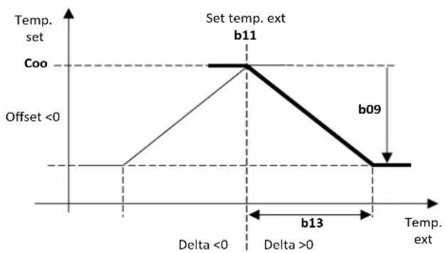
The regulator allows you to modify the set-point by adding up the value according to the temperature of the outdoor air probe. To use this function, edit the values from parameter b08 to b14 following the information below (edited by the installer).
Parameters of regulator PAr -> rE
- b08 enable = 1/disable=0 dynamic set-point.
- b09 = maximum cooling offset.
• b10 = maximum heating offset. - b11 = Cooling outdoor temperature setting.
- b12 = Heating outdoor temperature setting.
• b13 = Cooling temperature delta.
• b14 = Heating temperature delta.
Edit the setpoint depending on the outdoor temperature:
HEATING COOLING

6.1 SETTINGS FOR STANDARD CLIMATIC CURVES
HEATING COOLING


| CURVE | Setpoint Heat | Setpoint Cool | b08 | B09 | b10 | B11 | b12 | B13 | b14 |
| A | 20°C | -- | 1 | -- | 13°C | -- | 20°C | -- | -25°C |
| B | 20°C | -- | 1 | -- | 18°C | -- | 20°C | -- | -27°C |
| CURVE | Setpoint Heat | Setpoint Cool | b08 B09 | b10 B11 | b12 B13 | b14 | ||||
| C | 20°C | -- | 1 | -- | 25°C | -- | 20°C | -- | -29°C | |
| D | 40°C | -- | 1 | -- | 10°C | -- | 20°C | -- | -28°C | |
| E | 40°C | -- | 1 | -- | 15°C | -- | 20°C | -- | -25°C | |
| F -- 5°C | 1 | 5°C -- 37°C -17°C -- | ||||||||
| G -- 10°C | 1 | 8°C -- 40°C -20°C -- |
6.2 EDIT THE SET-POINT FROM 0-10V INPUT OR FROM RATIOMETRIC INPUT
Another type of adjustment allows you to edit the setpoint by adding (or subtracting) a value depending on the 0-10V input (if enabled). To enable the function, set H22=40, and, if appropriate, edit the value of the parameter b15 (range 0-10), keeping in mind that if b20=0, 0-10Volt input, if b20=1, ratiometric input.
-b20 = 0 with input at 0 Volt, the current setpoint: (Coo/Hea) setting - b15/2
-b20 = 0 with input at 5 Volt, the setpoint will be that set (Coo/Hea)
-b20= 0 with input at 10 Volt, the current setpoint: (Coo/Hea) setting + b15/2
![| 0 - 10 V Input [V] | New Set point [°C] | | ------------------ | ------------------ | | 0 | 0 | | 5 | 5 | | 10 | >5 |](/content/2026/05/1045894/images/96b7c891016418318b1f3948d8056e2595860c3d078bcda82d479d9b0584b0f3.jpg)
The signal must be applied to terminals X-22.1 and X-22.2- (see wiring diagrams).
-b20 = 1 with input at 0%, the current setpoint: (Coo/Hea) setting - b15/2
-b20 = 1 with input at 50%, the setpoint will be that set (Coo/Hea)
-b20 = 1 with input at 100%, the current setpoint: (Coo/Hea) setting + b15/2
![| Ratiometric Input | New Set point [°C] | | ----------------- | ------------------ | | 0% | -b₁₅/2 | | 50% | 0 | | 100% | >b₁₅/2 |](/content/2026/05/1045894/images/7a5e5cea1ba5cbc0493fd03b80fc10ea26847454f3504e520fee578a672cfe4f.jpg)
Through the terminal block, connect X-22.1 and X-22.2, while for +5V connect it directly to pin 3 of CN7 (pin 28 of the controller).
| Connector | PIN 1 | PIN 2 | PIN 3 |
| CN7 | GND | Undervoltage input | +5V |
| Terminal block | X-22.1 | X-22.2 | Connect it directly to pin 3 of CN7 of the controller |
NOTE: in "cooling" mode, having considered that the default cooling setpoint is 7°C , the parameter b15 must not have a value of 6 or higher to prevent the new setpoint set by 0-10V input from being lower than the antifreeze triggering threshold (4°C) .
7. CIRCULATOR
The circulator of the heat pump can be set in the following operating modes: • operation on call by temperature controller
- operating on call by temperature controller with periodic activation;
• continuous operation (default);
The circulator is switched off immediately if:
- There is a manual reset pump block alarm, including the flow switch alarm;
- With remote input in standby or off, the pump (if running) is always switched off with a delay equal to P02 in tenths of a minute (default P02=2)
The circulator can be configured with P03 to operate independently from the compressor or on call. 0=continuous operation in heating/cooling mode(default P03=0)
1=operating on call by temperature controller
Note: with automatic reset flow switch alarm triggered, the circulator is on even if the compressor is off. The circulator is always on when the antifreeze heaters are running and if operation of the hydraulic pump in antifreeze is enabled. Antifreeze operation is enabled if the regulation temperature drops below P04 °C (default 5°C), and disables if the regulation temperature rises above P04+P05 °C (Default value P05=2,0°C).
7.1 CONTINUOUS OPERATION [P03=0] - Default
The circulator is only off with the unit OFF, in all other cases it is always on.
7.2 OPERATION ON CALL BY TEMPERATURE CONTROLLER [P03=1]
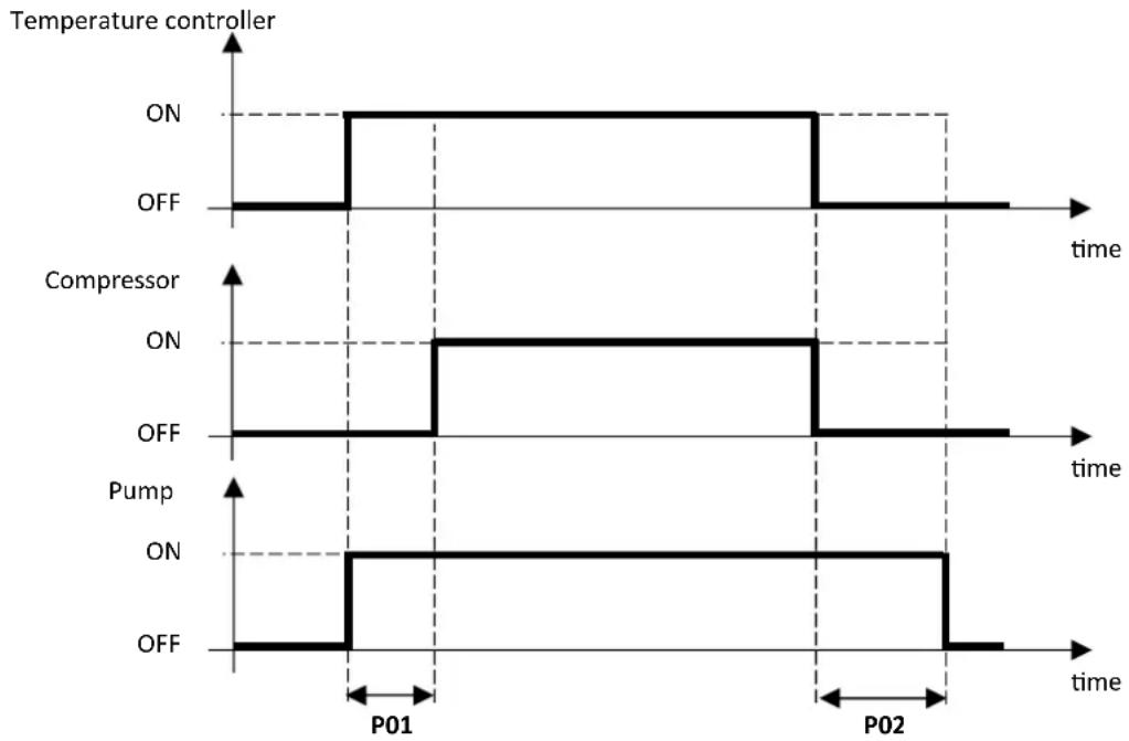
In this operating mode, the circulator is active on demand by the temperature controller, after a delay time of P01 seconds (default P01=30) from when the pump switched on, the compressor switches on as well.
Whereas when switching off, the pump is deactivated after a delay time of P02 minutes (default P02=2) from when the compressor switches off. With automatic reset flow switch alarm triggered, the circulator is on even if the compressor is off.
7.3 OPERATING ON CALL BY TEMPERATURE CONTROLLER WITH PERIODIC ACTIVATION
The function is disabled if P17=0 (default).
If P03=1, the circulator turns on periodically for a time defined by the parameter P17 (in seconds) after a count, lasting a time set by parameter P16 (in minutes), activated when the pump switches off because temperature control fulfilled.
With automatic reset flow switch alarm triggered, the pump is on even if the compressor is off.
The periodical function is a suspended if the antifreeze protection trips.
7.4 OPERATION WITH HEATER ACTIVE
See paragraph 10.8.
7.5 PROPORTIONAL REGULATION OF THE CIRCULATOR
The speed of the circulator changes depending on the temperature difference between the inlet water and outlet water of the heat exchanger, according to the diagram below, where:
• P07: Maximum speed = 100%
• Minimum speed = 75%
- P09: modulating pump inlet/outlet water Delta T setting (°C) (according to model)
• P10: Modulating pump Delta = 3°C (default)
![| ΔT [°C] | Speed [%] | |---|---| | P06 | 0 | | P07 | 100 | | P08 | 100 | P06/P09 (labeled) | 100 |](/content/2026/05/1045894/images/e0b6ea93a060d90077bd5d36c6c252f63158f82d49625e393cbf6718f18b32df.jpg)
The circulator is at maximum speed in DHW production.
Note: If the parameter r33 > 0, then the circulator can be running on call even to activate the system and/or sanitary heater, see par.10.8.
7.6 SYSTEM VENTING
Function used to vent the system, with the circulator at maximum speed.
To enable the function:
- Controller OFF
- Access the parameters PRG ->PSS ->PRG -> (enter Service password)
- Press the UP and DOWN keys simultaneously for 3 seconds
The circulator switches on at maximum speed, and then switches off after 5 minutes.
The system venting cycle can be exited manually by pressing the MODE/ESC key, or by pressing the UP and DOWN keys simultaneously for 3 seconds.
During this function, the flow switch alarm is disabled, the maintenance technician must guarantee that there is water inside the system.
8. COMPRESSOR OR ACTIVATION LOGIC
The restart of compressors is in operation of a set point referred to the inlet water temperature. It is based on calculation of Si basa sul calcolo di ΔTset which is the difference between outlet water temperatures and inlet water temperatures, detected while the compressor for thermoregulation is turning off.
8.1 REGULATION IN COOLING MODE
- Tw,out,set = adjusted setpoint in cooling
- ΔT, set = Tw, out, set - Tw, in, set
- b05 = compressor delta cut-off set= 0,2°C (default)
• b25 = delta cut-on compressor set= 2°C

- The compressor shutdown is set by the parameter b05: the compressor shutdown when Tw,out < Tw,out,set - b05
- The compressor restart starts when Tw,out > (Tw,out,set + ΔT,set + b25)
EXCEPTION: if ΔT , set > 8°C, the compressors restart when the discharge probe temperature is lower than the setpoint 10°C: Tw, out > (Tw, out, set + 10°C).
8.2 REGULATION IN HEAT MODE
- Tw,out,set = setting setpoint in heat mode
-
ΔT, set = Tw, out, set - Tw, in, set
-
b05 = compressor regulation delta cut-off = 0,2°C (default)
• b25 = compressor regulation delta cut-on = 2°C
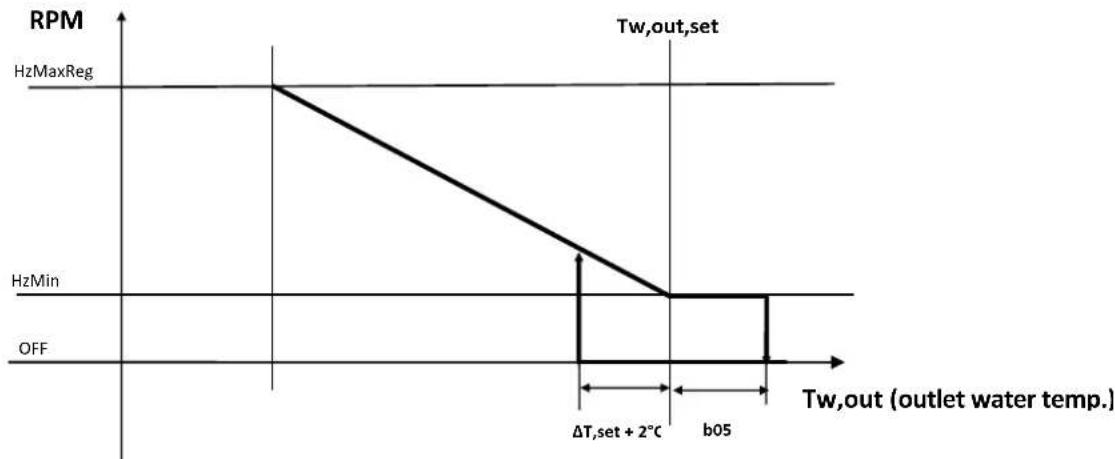
- The compressor shutdown is regulated by parameter b05: the compressor shutdown when is regulated by parameter b05 Tw,out > Tw,out,set + b05
- The compressor restart when: Tw,out < (Tw,out,set - ΔTset - b25)
EXCEPTION: if ΔT , set > 8°C, the compressors restart when the discharge probe temperature is lower than the setpoint 10°C: Tw,out < (Tw,out,set - 10°C)
9. DISSIPATION FAN CONTROL
The dissipation control depends on the condensing pressure in chiller mode, while it depends on the evaporation pressure in heat pump mode. Ventilation control depends on operation of the compressor.
A pre-ventilation occurs every time the compressor switches on and off.
10. CONTROLLER FUNCTIONS
The following is a list of the functions which can be activated in the machine controller; not all of them can be selected simultaneously. Values other than the default values can jeopardise proper operation of the unit. If in doubt on which value to set, contact our headquarters.
10.1 ANTIFREEZE PROTECTION HEATERS (IF KA ACCESSORY IS AVAILABLE)
If the optional KA kit is present, the function is active by default.
The water antifreeze heaters on the faces of the evaporator plates even activate with the machine off (but powered) when the delivery water temperature drops below r02 °C (default 4°C) in "heating" mode or below r03 °C (default 4°C) in "cooling" mode or when switched "OFF". The heaters are switched off when the temperature measured by the outlet water probe exceeds r02+r06 in "heating" or r03+r06 in "cooling" or when "OFF" (default value r06=2.0 °C).
The heating cable at the base of the machine activates when the outdoor air temperature drops below 3° C. It deactivates when the outdoor temperature rises above 5° C.
10.2 ENABLING DOMESTIC HOT WATER PRODUCTION
To activate the domestic hot water functions, connect a probe to be placed inside the tank to terminals X17.1-X17.2 (enabled as analogue input). The sanitary function must be enabled after positioning and connecting the temperature probe.
| I/O resource - Parameter VALUE Function | ||
| H10 | 0 (default) Function disabled | |
| 1 | Function active in heating and cooling mode.The remote on-off function does not disable DHW production. | |
| 2 | Function active in heating and cooling mode.The remote on-off function disables DHW production. | |
| 3 | Function active in heating mode.The remote on-off function does not disable DHW production. | |
| 4 | Function active in heating mode.The remote on-off function disables DHW production. | |
| 5 | Function active in cooling mode.The remote on-off function does not disable DHW production. | |
| 6 | Function active in cooling mode.The remote on-off function disables DHW production. | |
| ST6 can be activated via H17 6 DHW temperature probe enabling | ||
| DO6 can be activated via H84 6 DHW valve control | ||
If the domestic hot water temperature is lower than its setting (set by default at 48° C, edited by accessing the menu PRG->Set->SAN) the machine activates the DHW valve and the compressor is set at maximum frequency, starting modulation one degree before the setting and switching off one degree after. When the set point is reached, the valve goes back to the rest condition and the compressor starts to regulate normally.
Switching from utility water to domestic hot water, the working probe changes from "water outlet probe" to "DHW tank probe". Switching from winter mode to sanitary mode, the compressor does not switch off and is brought to the maximum frequency established by the controller, whereas switching from summer mode to domestic hot water, the compressor is switched off and waits a safety time.
Defrosting is always carried out in winter mode on the utility side, and never on the domestic hot water tank.
NOTE:
-If H10 = 1/3/5. Switching off the unit by remote control (remote on-off, see paragraph 10.4.1) does not affect domestic hot water operation. The unit goes to priority sanitary mode just powered on. The display on the machine shows the temperature detected by the probe inside the DHW tank. When the sanitary cycle has finished, the display goes back to showing the water outlet probe temperature.
If the remote ON-OFF digital input (terminals 15.1 / 15.2) is open, with sanitary function enabled (H10=1 and H20=6), the wording "SAN" will appear on the machine display. When the sanitary cycle has finished, the display goes back to showing "E00" indicating that the remote ON-OFF contact is open.
-If H10 = 2/4/6, the remote on-off function disables domestic hot water production and operation of the heat pump in heatin and cooling mode, system side.
10.2.1 MEMORISING THE PROBE IN HEATING MODE
Switching from utility water to domestic hot water, the working probe changes from "water outlet probe" to "DHW tank probe". For this reason, in heating mode, before entering sanitary mode, the last value read by the heat pump delivery probe is stored.
When sanitary temperature control is fulfilled, the system side temperature of reference goes back to that previously stored. The memory function interrupts:
- when the temperature read by the probe becomes lower than the stored value;
- or when a time equal to b06 seconds (default b06 = 45) has elasped.
10.2.2 HEATING MODE ON DHW STORAGE TANK
If the parameter H130=1, the machine exploits the DHW storage tank even for central heating. In these conditions, the outlet of the DHW valve is also enabled during operation in heating mode and not only in sanitary mode. The valve is deactivated during defrosting and in cooling mode. When H130=1, the DHW integration heater can be enabled also to act as system integration heater: to do this, set r10=1 e r15=2 (for other r15 settings see Paragraph 10.6.3); furthermore no digital output must be set as system integration heater.
10.2.3 INSUFFICIENT HEAT EXCHANGE IN A DHW SYSTEM
During DHW production, if the heat pump flow probe detects a temperature higher than 60° C, the DHW valve output is de-energised (DO6), and the value of the DHW probe at this time is recorded (Tsan,set).
-if the operation is San or Cool+San the compressor is stopped.
-If the operation is Heat+San, the system evaluates for b06 seconds whether there is a demand for heating from the system. If the system requires it, the compressor continues to work on the system, otherwise it is switched off.
-If the DHW resistor is present (e.g. DO3, H81=26), r15 = 0 or 1 and r24=2 or 3 it is activated until the DHW setpoint detected by the DHW probe is met (and any offset).
The compressor restarts when the flow temperature of the heat pump falls below 60° C again and the temperature measured by the DHW probe is lower than Tsan, set - 4° C.
10.3 REMOTE-CONTROLLED FUNCTIONS
Not all of the configurations can be activated and/or modified at the same time
The terminal block has digital inputs to control the unit via an external consent.
10.3.1 ON/OFF
The function is enabled by default on digital input ID 3 (terminals X15.1/X15.2).
Remove the terminal block jumper to place the unit in standby (the text "E00" appears on the controller display). When the contact closes, the machine comes out of standby and the circulator switches on for 2 minutes.
Function enabled by default (Parameter H47=2).
I/O Resource- Parameter Function
ID3 can be activated via H47 Enables remote On /Off function
If the unit is switched off by remote control during defrosting, the heat pump finishes defrosting and then places itself in off mode via remote control.
10.3.2 SUMMER/WINTER MODE CHANGE
The function can be set on digital input ID 2 (terminals X16.1/X16.2).
Heating or cooling mode of the heat pump can be managed by remote control.
I/O resource - Parameter Value Function
ID2 can be activated via H46 3
Open contact -> heat pump in cooling mode. Closed contact -> heat pump in heating mode.
The poles of the digital input can be swapped by setting H75 = 2
10.3.3 DHW ENABLE FROM DIGITAL INPUT
Function which can be activated instead of managing the double setpoint.
If DHW mode is enabled, instead of using the temperature probe, the domestic hot water function can be activated by the opening/closing of a digital input on the unit. This function is recommended when using two or more heat pumps in cascade hydronically connected to the same domestic hot water storage tank; this way activation of the domestic hot water function is controlled by the tank probe connected to the first unit, while the other units are enabled automatically by digital consent.
The system goes to sanitary mode when the digital input closes and exits DHW production when it opens.
| I/O resource - Parameter Value Function | ||
| ID9 can be activated via H53 28 | Closed contact ->active DHW call.Open contact ->inactive DHW call. | |
The poles of the digital input can be swapped by setting H76=1
The SAN setpoint of the heat pump is not considered, the designer is in charge of managing this setpoint, taking into account domestic hot water protection and configuration of the entire system.
10.4 SYSTEM WATER REMOTE PROBE
In some engineering solutions (e.g. heat pump in parallel to boiler on same hydronic circuit and shut off diverter valve) it could be necessary to enable a system remote temperature probe so that the controller can correctly process the management.
| I/O resource- Parameter Value Description | |
| ST7 can be activated via H18 41 Enables plant remote probe |
In the presence of the system remote probe, if the storage tank temperature is satisfied, it is avoided to activate the compressors even if the regulation probe requires it.
The conditions for the application of thermoregulation lockout are as follows:
- the heat pump is not performing DHW
- the heat pump is not defrosting
- all compressors are switched-off
The blocking conditions are as follows:
| Operating mode Blocking conditions of thermoregulation | |
| heating System remote probe > setpoint - b22 | |
| cooling System remote probe < setpoint + b22 | |
Nota: b22=5°C. See paragraph 13.
10.5 AUXILIARY HEATERS
In certain engineering solutions, it could be necessary to use an additional heater for the plant or for domestic hot water. Parameter r24 must be set to define the operating mode of the additional heaters:
- r24=0 integration heaters not used;
-r24=1 only plant integration heater used;
- r24=2 only DHW integration heater used;
- r24=3 both plant and DHW integration heaters used.
10.5.1 PLANT HEATER
If the regulation temperature remains below water setpoint in heating (Hea) - 0.5°C for a time equal to r12 the integration heater is activated according to operation of the machine in joint time slots or in substitution, as indicated in Paragraph 10.11.
The heater switches off when the setpoint is reached (also taking into account an offset set with parameters r29 or r30).
If the regulation temperature remains below the water setpoint minus r11 (°C) and the machine is blocked due to triggering of an alarm, the heater switches on. It switches off when the machine exits the alarm block.
| I/O resource - Parametro Value Function | ||
| r10 1 Function enabling | ||
| r11 0.5°C (default) Heaters in heating integration delta | ||
| r12 | 10 minutes (default) | Heaters in heating integration delta |
| r24 | 1/3 | Type of use of heaters |
| D03 can be activated via H81 | 22 | Plant integration heater |
10.5.2 PLANT HEATER IN DEFROST
During the defrost cycle (see Paragraph 10.12.2), setting r21=1 (in addition to r10=1 and r24=1 or 3) activates the plant side electric heater, if requested (regulation temperature lower than water setpoint -r11(°C), without waiting the time defined by r12.
10.5.3 DHW HEATER
Function which can be activated instead of managing the plant heater
This is an additional resource for heating the domestic hot water storage tank if the compressor alone is not capable of fulfilling the request in a reasonable time.
If domestic hot water production lasts longer than r16 (minutes) or if the machine blocks due to triggering of an alarm, the heater switches on. It switches off when the unit finishes domestic hot water production (also taking into account an offset on the setpoint with parameter r31, as explained in Paragraph 10.11.1).
| I/O resource - Parameter Value Function | ||
| r15 1 Function enabling | ||
| r16 10 minutes (default) DHW integration activation delay | ||
| r24 2/3 Type of use of heaters | ||
| D03 can be activated via H81 26 Plant integration heater | ||
Note: The domestic hot water function must be enabled (see paragraph 10.2)
10.5.4 SINGLE PLANT/DHW INTEGRATION HEATER
By configuring the DHW integration heater, it is possible to use this heater declared also as plant integration heater, setting the parameter r15=2 and r24=3.
In case of plant integration demand, the heater declared as DHW integration is activated, thus allowing to have a single integration heater for plant, domestic hot water and plant under defrost.
10.6 INTEGRATION HEATER SELECTION MODE
The priority can be set in the order to activate the plant side and sanitary side integration heaters; specifically the configurations are:
- r14=0 (default), the heaters can be activated simultaneously, if present;
- r14=1, the heaters can be activated, excluding one another:
2.1. r20=0, priority to the plant (the DHW heater only switches on if the temperature control for the plant side heater is fulfilled);
2.2.r20=1, priority to DHW (the plant side heater only switches on if the temperature control for the sanitary side heater is fulfilled).
10.7 CIRCULATOR MANAGEMENT WITH HEATER ON
The circulator of the heat pump can be activated when the plant and/or DHW integration heaters are active with the compressors not running (by substitution, by alarm or by integration in bracket II or III).
-r33 = 0: The circulator of the heat pump is activated on demand of the compressors or boiler,
-r33 = 1: The circulator of the heat pump is activated if the plant heater is active.
-r33 = 2: 2: The circulator of the heat pump is activated if the DHW heater is active.
-r33 = 3: The circulator of the heat pump is activated if the plant or DHW heater is active.
The circulator switches off after post-pumping (P02).
10.8 BOILER ENABLING
Function which can be activated instead of managing the double setpoint.
This is an additional resource to enable the boiler in integration or substitution of the heat pump.
Define the use mode by setting the parameter r23:
- r23=0 (default) boiler not used (operating priority of heaters);
- r23=1 only boiler on plant used (operating priority of heaters);
- r23=2 only DHW boiler used (operating priority of heaters);
- r23=3 DHW and plant boiler used (operating priority of heaters);
- r23=4 only boiler on plant with priority used (no heater operating priority);
- r23=5 only boiler in sanitary with priority used (no heater operating priority);
- r23=6 boiler on plant and in sanitary with priority used (no heater operating priority);
Define the supply of the boiler, setting parameter r32:
- r32 = 0: boiler without circulator with temperature control by heat pump,
- r32 = 1: boiler with autonomous circulator with temperature control by heat pump;
- r32 = 2: boiler without circulator with autonomous temperature control;
- r32 = 3: boiler with circulator with autonomous temperature control.
| I/O resource- Parameter Value Function | ||
| r10 1 | Plant integration enabling | |
| r12 | 10 minutes (default) | Plant integration activation delay |
| r15 1 DHW integration enabling | ||
| r16 | 10 minutes (default) | DHW integration activation delay |
| r23 | 1 ÷ 6 | Type of use of boiler |
| r32 | 1 ÷ 3 | Boiler supply |
| DO3 can be activated via H81 | 29 | Boiler enabling |
10.9 ACTIVATIONOFINTEGRATIONHEATERSANDBOILERINJOINTOPERATIONANDINSUBSTITUTION OF HEAT PUMP COMPRESSOR
The auxiliary parts that can be used for joint operation or for operation in substitution are:
- boiler
- plant integration heater
• DHW integration heater
Considering the operating modes in heating and/or DHW, there are 4 operating areas:
![graph TD A["Outside temp."] --> B["r22"] B --> C["Heat pump STANDARD WORKING"] B --> D["Heat pump + Boiler/Heater JOINT OPERATION I ZONE"] B --> E["r28"] E --> F["Boiler + Heat pump/Heater JOINT OPERATION II ZONE"] E --> G["r08"] G --> H["Boiler/Heater OPERATION IN SUBSTITUTION"]](/content/2026/05/1045894/images/68bf8af4ee4a2c1922063b105c516f21a6f8b9857d782b0429604aa919216180.jpg)
If you need to change the values of the parameters r22, r28, r08, follow r22 ≥ r28 ≥ r08 .
Setting r22=r28 allows you to eliminate the zone relative to joint operation bracket I; setting r28=r08 allows you to eliminate the zone relative to joint operation bracket II; setting r22=r28=r08 allows you to eliminate both brackets relative to joint operation.
Do not modify value r08, as it could jeopardise operation of the unit
Normale operation of the heat pump in which the integration heaters and-or the boiler only intervene when a heat pump alarm is triggered.
If the outdoor temperature is between r22 and r28, the compressor operates in synergy with the auxiliary heaters in winter or DHW mode.
In this operating bracket, first the heat pump is activated and after r12 minutes the plant side auxiliary heaters, or after r16 minutes the sanitary side auxiliary heaters.
The intervention priorities are defined by the parameters r14, r20, r23, r24.
It goes back to normal operation if the outdoor temperature is greater than r22+1.0 (°C).
NOTE: In the joint operating bracket, the boiler is temperature controlled by the plant water remote probe (if enabled). In particular, if the temperature detected by the remote probe is lower than the Hea setpoint, the boiler is switched on and then will go off when the temperature detected by the remote probe is higher than the Hea setpoint. The heat pump follows the activation logic described in paragraph 10.5.
If the remote plant water probe is not enabled, the boiler will be managed by the delivery probe of the heat pump.
If the outdoor temperature is between r28 and r08, the compressor operates in synergy with the auxiliary heaters.
In this operating bracket, first the boiler is activated, then the heat pump and auxiliary heaters intervene after a time defined by r12 (minutes) for the plant side and r16 (minutes) for the sanitary side
The intervention priorities are defined by the parameters r14, r20, r23, r24.
It goes back to normal operation if the temperature rises above r28+1.0 (°C).
Note: In the joint operating bracket, the boiler is temperature controlled by the plant water remote probe (if enabled). In particular, if the temperature detected by the remote probe is lower than the Hea setpoint, the boiler is switched on and then will go off when the temperature detected by the remote probe is higher than the Hea setpoint. The heat pump follows the activation logic described in paragraph 10.5.
If the remote plant water probe is not enabled, the boiler will be managed by the delivery probe of the heat pump.
10.9.4 OPERATION IN SUBSTITUTION
If the outdoor temperature drops below r08 use of the heat pump compressor will be inhibited.
- If the auxiliary system is composed of plant and/or DHW heaters, they are active in substitution of the compressor with defined times, r12 (minutes) for plant side and r16 (minutes) for sanitary side.
Whereas in the operation in substitution bracket, the integrations do not need to be enabled with r10 or r15 as the heaters need to operate in substitution (and not in integration) of the heat pump (therefore simply select the type of use with the parameter r24).
- If the auxiliary system is a boiler with autonomous circulator (r32 = 1 or 3).
The circulator of the heat pump is off, after P01 (default 30 seconds) the boiler is enabled.
NOTE: With water side antifreeze protection, the pump used is activated (or remains active) anyhow.
- If the auxiliary system in substitution is a boiler with autonomous temperature control (r32 = 0 or 2).
The boiler is enabled regardless of the temperature control of the heat pump.
- If the auxiliary system in substitution is a boiler without circulator (r32 = 0 or 2).
The circulator of the heat pump is on when the boiler is enabled.
The compressor switches back on if the temperature rises above r08+ r09 (°C) (r09=1.0 °C by default).
10.10 OPERATING BRACKETS - ACTIVATION OF INTEGRATION HEATERS (PLANT REMOTE WATER PROBE NOT ENABLED)
The possible configurations of the integration parameters are listed in tables 1,2,3 and 4 shown below, divided by operating brackets (the operating modes and possible values of the parameters are indicated in the "STATUS" boxes and in the parameters "rxx" so that a given order
of intervention of the integrations occurs in a certain operating mode of the unit; other statuses and values of the parameters can be selected instead and therefore they are provided in the same cell separated by the symbol "/").
| N° | INTERVENTION ORDER(with setpoint not reached) | STATUS | OPERATION | r10 | r15 | r12 | r16 | r23 | r24 |
| 1 | 1) Heat pump2) After r12 minutes,plant integration heater | HEAT/HEAT+SAN | HEAT | 1 | 0/1/2 | Set the minutes | / | 0/2/5 1/3 | |
| 2 | 1) Heat pump2) After r12 minutes,boiler | HEAT/HEAT+SAN | HEAT | 0/1 | 0/1/2 | Set the minutes | / | 1/3/4/6 | 0/2 |
| 3 | 1) Heat pump2) After r12 minutes,plant integration heater3) After further r12 minutes,boiler | HEAT/HEAT+SAN | HEAT | 1 | 0/1/2 | Set the minutes | / | 1/3 | 1/3 |
| 4 | 1) Heat pump2) After r12 minutes,boiler3) After further r12 minutes,plant integration heater | HEAT/HEAT+SAN | HEAT | 1 | 0/1/2 | Set the minutes | / | 4/6 | 1/3 |
| 5 | 1) Heat pump2) After r16 minutes,plant integration heater | HEAT+SAN | DHW | 0/1 | 1 | / | Set the minutes | 0/1/4 2/3 | |
| 6 | 1) Heat pump2) After r16 minutes,boiler | HEAT+SAN/ | DHW | 0/1 | 0/1/2 | / | Set the minutes | 2/3/5/6 | 2/3 |
| 7 | 1) Heat pump2) After r16 minutes,plant integration heater3) After further r16 minutes,boiler | HEAT+SAN | DHW | 0/1 | 1 | / | Set the minutes | 2/3 | 2/3 |
| 8 | 1) Heat pump2) After r16 minutes,boiler3) After further r16 minutes,DHW integration heater | HEAT+SAN | DHW | 0/1 | 1 | / | Set the minutes | 5/6 | 2/3 |
| 9 | 1) Heat pump2) After r12 minutes,plant/DHW integration heater | HEAT/HEAT+SAN | HEAT/DHW | 1 | 1 | Set the minutes | Set the minutesi | 0 | 3 |
TABLE 2. JOINT OPERATION, BRACKET 1
| N° | INTERVENTION ORDER(with setpoint not reached) | STATUS OPERATION r10 r15 r12 r16 r23 r24 | |||||||
| 10 | 1) Heat pump2) After r12 minutes, boiler | HEAT /HEAT+SAN | HEAT/DHW 0/1 0/1/2 | Set the minutes | Set the minutes | 3/6 0 | |||
| 11 | 1) Heat pump2) After r12 minutes, plant/DHW integration heater3) After further r12 minutes, boiler | HEAT /HEAT+SAN | HEAT/DHW 1 1 | Set the minutes | Set the minutes | 3 | 3 | ||
| 12 | 1) Heat pump2) After r12 minutes, boiler3) After further r12 minutes, plant/DHW integration heater | HEAT /HEAT+SAN | HEAT/DHW 1 1 | Set the minutes | Set the minutes | 6 | 3 | ||
TABLE 3. JOINT OPERATION, BRACKET 2
| N° | ORDINE INTERVENTO(with setpoint not reached) | STATUS OPERATION r10 r15 r12 | r16 r23 | r24 | |||||
| 1 | 1) Boiler2) After r12 minutes,heat pump | HEAT /HEAT+SAN | HEAT | 0/1 | 0/1/2 | Set the min-utes | / | 1/3/4/6 | 0/2 |
| 2 | 1) Boiler2) After r12 minutes,plant integration heater3) After further r12 minutes,heat pump | HEAT /HEAT+SAN | HEAT | 1 0/1/2 | Set the min-utes | / | 1/3 1/3 | ||
| 3 | 1) Boiler2) After r12 minutes,heat pump3) After further r12 minutes,plant inte-gration heater | HEAT /HEAT+SAN | HEAT | 1 0/1/2 | Set the min-utes | / | 4/6 1/3 | ||
| 4 | 1) Plant integration heater2) After r12 minutes,heat pump | HEAT /HEAT+SAN | HEAT | 1 0/1/2 | Set the min-utes | / | 0/2/5 | 1/3 | |
| 5 | 1) Boiler2) After r16 minutes,heat pump | HEAT+SAN | DHW | 0/1 | 0/1/2 | / | Set the min-utes | 2/3/5/6 | 0/1 |
| 6 | 1) Boiler2) After r16 minutes,DHW integration heater3) After further r16 minutes,heat pump | HEAT+SAN | DHW | 0/1 | 1 | / | Set the min-utes | 2/3 2/3 | |
| 7 | 1) Boiler2) After r16 minutes,heat pump3) After further r16 minutes,DHW inte-gration heater | HEAT+SAN | DHW | 0/1 | 1 | / | Set the min-utes | 5/6 2/3 | |
| 8 | 1) DHW integration heater2) After r16 minutes,heat pump | HEAT+SAN | DHW | 0/1 | 1 | / | Set the min-utes | 0/1/4 | 2/3 |
| 9 | 1) Boiler2) After r12 minutes,heat pump | HEAT /HEAT+SAN | HEAT/DHW | 1 1 | Set the min-utes | Set the min-utes | 3/6 0 | ||
| 10 | 1) Boiler2) After r12 minutes,plant/DHW inte- gration heater3) After further r12 minutes,heat pump | HEAT /HEAT+SAN | HEAT/DHW | 1 1 | Set the min-utes | Set the min-utes | 3 | 3 | |
| 11 | 1) Boiler2) After r12 minutes,heat pump3) After further r12 minutes,plant/ DHW integration heater | HEAT /HEAT+SAN | HEAT / SANITARIO | 1 1 | Set the min-utes | Set the min-utes | 6 | 3 | |
| 12 | 1) Plant/DHW integration heater2) After r12 minutes,heat pump | HEAT /HEAT+SAN | HEAT/DHW | 1 1 | Set the min-utes | Set the min-utes | 0 | 3 | |
Table 5 shows the settings to be configured to enable the integrations in “summer and sanitary” mode (in this case the only activation that can be activated is the DHW integration heater and the division into operating brackets does not apply).
| TABLE 5. OPERATION IN COOL+SAN (DHW RUNNING) | |||||||||
| N° | INTEGRATIONS INTERVENTION ORDER-With setpoint not reached after r16 minutes from the start-up of the compressor or with setpoint not reached with machine blocked by alarm. | STATUS | OPERATION | r10 | r15 | r12 | r16 | r23 | r24 |
| 1 | 1) DHW integration heater | COOL+SAN | DHW | 0/1 | 1 | / | Set the minutes | 0/1/2/3/4/5/6 | 2/3 |
Table 6 shows the behaviour of the plant and DHW integration heaters in all the operating modes of the unit.
| TABLE 6. INTEGRATION HEATERS OPERATION | ||||
| N° | STATUS | OPERATION | PLANT INTEGRATION HEATER | DHW INTEGRATION HEATER |
| 1 | HEAT+SAN | HEAT | Works as indicated in TABLE 1,2,3 and 4. | In “HEAT+SAN”, by default sanitary temperature control has priority over that of the plant, therefore if required by the temperature control, the unit goes to “SANITARY” mode and the DHW integration heater acts as indicated in TABLES 1,2,3 and 4. |
| 2 | HEAT+SAN | DHW | Only if all 3 of the following conditions are met:-the output is configured for Plant integration heater;-r24=1/3;-plant water temperature remote probe present and configured;the plant integration heater is activated in the following situations:- r12 minutes after the start of its count activated in “HEAT” mode previously running (see line 1);- if its count is not already activated in the previous “HEAT” mode, r12 minutes after the temperature control demand.- In SANITARY mode, with remote probe not configured, the plant integration heater is deactivated or any of its counts are interrupted.- With “remote on-off” contact open, the Plant integration heater is deactivated. | Works as indicated in TABLES 1,2,3 and 4. |
| 3 | COOL+SAN | DHW | Cannot be activated | Works as indicated in TABLE 5. |
| 4 | COOL+SAN | COOL | Cannot be activated | Cannot be activated |
10.10.1 AUXILIARY SYSTEMS OFFSET MANAGEMENT
Lastly you may establish that the boiler and/or integration heaters (according to the resources and selected priorities) have a setpoint in heating mode and in sanitary mode higher than that of the heat pump. This is achieved by setting an offset on the following setpoints:
- r29 = First setpoint temperature offset for boiler and plant heaters (G02);
- r30 = Second setpoint temperature offset for boiler and plant heater (G05);
- r31 = Temperature offset for boiler and DHW heaters (G03);
This way the heat pump stops at the setpoint (G02,G03,G05) and the temperature difference, according to the set outset, will be supplied by the boiler and/or heaters.
10.11 WARNINGS
If the double setpoint function is not active, one of the following warnings can be configured.
10.11.1 PLANT SEASON
A digital output can be configured indicating the operating season of the unit, plant side. The output is active in summer mode, while it is deactivated in OFF or heating mode. During DHW production and defrosting, the output maintains the setting of the source season.
| I/O Resource (Parameter) Value Function | ||
| DO7 can be activated via H85 31 | Plant season warning | |
10.11.2 ALARM
A live output can be configured signalling the presence of an alarm.
| I/O Resource Parameter Value Function | |
| DO7 can be activated via H85 47 Alarm warning |
10.11.4 DEFROST
A digital output can be configured signalling defrosting in progress.
| I/O Resource Parameter Value Function | ||
| DO7 can be activated via H85 21 | Defrost in progress warning | |
10.12 DEFROST CYCLE
The defrost cycle is only active in heat pump mode and is used to prevent the formation of ice on the surface of the air/air coil. The formation of ice on the evaporator, which is quite frequent with very low outdoor temperatures, in addition to considerably downgrading the thermodynamic performance of the unit, also risks damaging the unit itself.
If the unit is switched off by remote control during defrosting, the heat pump finishes defrosting and then places itself in off mode via remote control.
10.13 COMPRESSOR CRANKCASE HEATER
The crankcase heater is activated if the compressor has been off for at least 30 minutes and if the discharge temperature is below a certain threshold of 20°C (with hysteresis of 2.0°C ). The crankcase heater is disabled when the compressor starts back up.
10.14 DOUBLE SET-POINT
This function introduces a second working set-point on the plant side, both in cooling and heating mode. The user terminal board allows a consent to be connected to switch from the first to the second set-point and configured at digital input ID9 with parameter H53 = 26. The valve, on the other hand, is connected in the terminal board to digital output DO7 and is configured via parameter H85.
| Parameter | VALUE | Function |
| H53 | 26 | Second set-point call |
| H85 | 25 | 3-way valve for radiant panels |
| H129 | 0 Function disabled (default) | |
| 1 | Function configured but not active | |
| 2 | Enabled only in cooling mode | |
| 3 | Enabled only in heating mode | |
| 4 | Enabled in cooling and heating mode | |
| H138 | 0 | DHW second setpoint function disabled (default) |
| 1 | Enabled the second DHW set point in cooling mode | |
| 2 Enabled the second DHW set point in heating mode | ||
| 3 | Enabled the second DHW set point in cooling and heating mode | |
10.15 MINIMUM HZ FUNCTIONALITY
Configuring parameter L02=1 and L03≠0 reduces the nominal operating Hz of the compressor.
| Parameter VALUE Function | ||
| L02 | 0 Function not active | |
| 1 Enabling minimum Hz | ||
| L03 | 0 Function not active | |
| 1 Function active only in cooling mode | ||
| 2 Function active only in heating mode | ||
| 3 Function active only in sanitary mode | ||
| 4 Function active in cooling and sanitary mode | ||
| 5 Function active in heating and sanitary mode | ||
| 6 Function active in cooling and heating mode | ||
| 7 Function always active |
With the function active, the output and power of the unit are limited, for additional information see the installer user manual. Configuring a digital input ID9 with parameter H53=21, the function can be managed.
| Parameter VALUE Function | ||
| H53 | 0 (default) Function disabled | |
| 21 | Open contact -> standard mode Closed contact -> mode Hz min/max |
10.16 MAXIMUM HZ FUNCTIONALITY
Activating the function increases the power of the unit, please contact us for information.
10.17 FLOWMETER
It is possible to connect a ratiometric flowmeter to CN7 terminals of the controller respecting the table below:
| Connector PIN 1 PIN 2 | PIN 3 | ||
| CN7 | GND | Voltage input | +5V |
| Terminal block | X-22.1 | X-22.2 | Connect it directly to pin 3 of CN7 of the controller |
Enable the parameter H22=45 (configuration ST11).
| I/O Resource - Parameter | Value | Function |
| H22 | 45 | Water flow |
The flowmeter must have the following characteristics:
• Signal range 0.5 ÷ 3.5V (0l/min at 0.25V)
- 5Vdc power supply
- Power <50mW
- Inductive load > 10kΩ
Once the flow meter is enabled, set the following parameters:
| Parameter | Value | Description |
| Ac09 | 2.0 | Minimum flowmeter rate |
| Ac10 | 0.5 | Flowmeter output at minimum flow |
| Ac11 | 40 | Maximum flow meter |
| Ac12 | 3.5 | Flowmeter outlet at the minimum flow rate |
11. FUNCTIONS THAT CAN BE ACTIVATED WITH HI-T2 ACCESSORY (OPTIONAL)
This is a touch screen remote control for centralised management of a chiller/heat pump network. It includes humidity and temperature sensors for the thermo hygrometric analysis of the environment and for the management of the double set point for radiant floor heating systems that use a dehumidification system.
The intuitive interface simplifies the use of the controller; all the functions can be easily set through the use of an easy to understand synoptic. The Hi-T remote control allows you to manage the following functions:
- Remote management;
• Management of a network, up to 7 heat pumps; - Zone thermostat;
- Screed function;
• Antilegionella disinfection;
• Double set-point and humidity measurement; -
Dew point control;
-
Climatic compensation;
- Booster circulator management;
- Management of single pump in a network;
- Alarm diagnostic system.
12. FUNCTIONS THAT CAN BE ACTIVATED WITH GI MODULE (OPTIONAL)
The Gi module is an optional kit which allows you to manage the following functions:
- Booster circulator management with the aid of a room thermostat (not supplied);
- Management of a plant side mixer valve both in heating and cooling mode;
- Solar – thermal integration management.
12.1 I/O RESOURCES OF THE CONTROLLER
The following is the list of I/O (inputs and outputs) that can be set to activate the functions of the controller.
| Resource Parameter | Terminal block | XGI | Factory configuration | Description | |
| Default value Function | |||||
| ST 5E H27 1.1 / 1.2 | 0 Not set | Analogue input configurable with an NTC-10KΩ probe at 25°C β 3435 | |||
| ST 6E H28 2.1 / 2.2 | 0 Not set | Analogue input configurable with an NTC-10KΩ probe at 25°C β 3435 | |||
| ST 7E H29 3.1 / 3.2 | 0 Not set | Analogue input configurable with an NTC-10KΩ probe at 25°C β 3435 | |||
| ID 9E H63 4.1 / 4.2 | 0 Not set Voltage-free digital input | ||||
| DO 1E H86 | 5.1 (phase)6.2(neutral) | 0 Not set | 230Vac, 50Hz, 2A (AC1) single-phase live output. | ||
| DO 2E H87 | 5.2 (phase)6.2(neutral) | 0 Not set | 230Vac, 50Hz, 2A (AC1) single-phase live output. | ||
| DO 3E H88 | 7.1 (phase)7.2(neutral) | 0 Not set | 230Vac, 50Hz, 2A (AC1) single-phase live output. | ||
| DO 4E H89 | 8.1 (phase)8.2(neutral) | 0 Not set | 230Vac, 50Hz, 2A (AC1) single-phase live output. | ||
| DO 5E H90 | 9.1 (phase)9.2(neutral) | 0 Not set | 230Vac, 50Hz, 2A (AC1) single-phase live output. | ||
GI terminal block
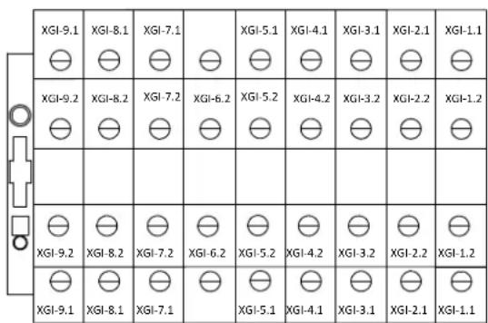
12.2 MANAGEMENTOFSECONDARYCIRCULATOR/BOOSTERPUMP(WITHROOMTHERMOSTAT)
It allows the management of a secondary or booster circulator to serve the plant.
A room thermostat (N.C.) must be appropriately configured.
- Thermostat closed contact -> The secondary circulator is activated;
- Thermostat open contact -> The secondary circulator is off with a delay given by P02 (post-pumping).
| I/O Resource - Parameter | Value | Function | XGI terminals |
| ID9E can be activated via H63 | 19 | Room thermostat | 4.1 / 4.2 |
| DO5E can be activated via H90 | 43 | Secondary circulator | 9.1 (phase) 9.2(neutral) |
With the Heat pump in Off, the booster circulator will be off regardless of the thermostat call.
If the machine is not equipped with either a remote system probe or a secondary circulator, the room thermostat thermoregulation is as follow:
| ROOM CALL | Compressor thermoregulations | |
| b30=0 | b31=1 | |
| Activated | Activated | Activated |
| Deactivated (satisfied environment) | ||
12.3 MIXER VALVE MANAGEMENT
The mixer valve is regulated by means of specific PID which strives to maintain the delivery temperature of the radiant panel at the set value.
The setpoint setting can be found in the 'Set' Menu:
rCoo = Mixer flow temperature setpoint in cooling mode = 15°C (default)
rHea = Mixer flow temperature setpoint in heating mode = 30°C (default
The resources and the parameters to be setting are the following:
| I/O resource - Parameter Description Value Function XGI terminals | ||||
| ST 5E can be activated via H27 | Analogue input 44 Mixer probe 1.1 / 1.2 | |||
| ID9E can be activated via H63 | Digital input 19 Room thermostat 4.1 / 4.2 | |||
| DO1E can be activated via H86 | Voltage output 34 Valve open command | 5.1 (phase) / 6.2(neutral) | ||
| DO2E can be activated via H87 | Voltage output 35 Valve close command 5.2 (phase) | |||
| DO3E can be activated vi H88 | Voltage output 33 | |||
| i01 Valve opening time | Recover the value from the technical data supplied installed | |||
| i02 Interval between two interruptions 30 seconds 1 | ||||
| i03 PID proportional band 2 °C 2 | ||||
| i04 | PID integral time | 300 seconds 3 | ||
| i05 | PID derivative time | 0 4 | ||
| i06 | Mixer management only active in heating mode | 1 | ||
| Mixer management only active in cooling mode | 2 | |||
| Mixer management only active in heating and cooling mode | 3 | |||
1 Recommended value. Time interval between one correction and the next.
2 Recommended value. Intervention area defined by the difference between the setpoint for the mixer flow and the temperature measured by mixing flow probe.
3 Recommended value. Time taken by the mixing valve to switch from open to closed and vice versa, when the difference between setpoint set for the flow of the mixing valve and the value read by the mixing probe is greater than or equal to proportional band. The more larger this value, the slower the change in approach to the setpoint set for the mixing valve flow.
4 Derivate component of regulation; use only if you have a good knowledge of regulator logic.
12.3.1 Determination of setpoint
The setpoint on which to perform regulation is given by rCOO or rHEA respectively in cooling and heating mode. If dynamic compensation of the setpoint is enabled (b08=1), then the setpoint will be corrected the same way as the heat pump/chiller.
The maximum and minimum value reached by the compensation are not controlled. Therefore the parameters must be configured so that the setpoints are not brought to unwanted values outside of the allowed work ranges.
12.3.2 Mixer pump
The mixing pump (DO3E) switches on when there is a call from the digital input ambient thermostat (ID9E) and switches off with a delay of P02 from the instant the thermostat call ceases.
12.4 SOLAR INTEGRATION MANAGEMENT
To enable the function, set S01=1.
| Parameter | Description | Value | Function | XGI terminals |
| ST6E can be activated via H28 | Analogue input | 39 | Solar storage tank probe | 2.1 / 2.2 |
| ST7E can be activated via H29 | Analogue input | 38 | Solar collector probe | 2.1 / 2.2 |
| DO3E can be activated via H88 | Voltage output | 30 | Solar circulator | 7.1 (phase) 7.2(neutral) |
| DO4E can be activated via H89 | Voltage output | 45 | Solar exhaust valve | 8.1 (phase) 8.2(neutral) |
12.4.1 Activation of solar circulator
Solar management is also active with the unit off.
The solar circulator is active in both of the following conditions are met:
- The temperature of the solar collector is higher than that defined by parameter S13;
- The temperature difference between the solar collector and that of the solar storage tank is higher than the parameter S02 (default 6°C).
12.4.2 Collector protection
If the temperature of the collector exceeds parameter S04 (default 110°C ), the solar circulator is periodically on intermittently with the times set in:
• S05 = time ON (default 15 seconds);
- S06 = time OFF (default 15 seconds).
As hysteresis to exit the protection condition use S08. This protection is guaranteed even with the machine Off.
12.4.3 Collector overtemperature alarm
If the collector probe exceeds the value of parameter S12, there is an alarm condition E10 which blocks the solar circulator. The hysteresis to return from the alarm condition is given by parameter S08. If an alarm is triggered, operation of the heat pump is guaranteed.
If the temperature of the DHW storage tank exceeds the parameter S10, the alarm E50 is triggered. The hysteresis to return from the alarm condition is given by parameter S11. If an alarm is triggered, operation of the heat pump is guaranteed.
12.4.5 Solar exhaust valve
If alarms E10 and E50 are triggered simultaneously, the solar exhaust valve will be activated.
It is recommended to connect the output of terminals 8.1 (phase) - 8.2 (neutral) to a timed relay to manage the flow of the exhaust valve.
12.4.6 Dissipation of solar tank heat
The solar circulator runs to dissipate excess heat in the storage tank by exploiting the solar collector if both of the following conditions are met: -The temperature of the DHW storage tank is higher than parameter S15; -The temperature of the solar collector is lower than 35° C (parameter S13 – parameter S14).
The solar collector is off when at least one of the following conditions is met:
-The temperature of the DHW storage tank is lower than parameter S15. -The temperature of the collector exceeds the parameter S13 (default 40°C ).
12.4.7 Antifreeze
Function active if the parameter S01 = 1. If the temperature of the solar collector is lower than parameter S07 (default 5°C), the solar circulator is activated in antifreeze mode. This protection is only enabled with the machine Off. The function is inhibited if the temperature of the DHW storage tank is lower than the value defined in parameter S16. Setting the parameter S01 = 2, the antifreeze function is never active (for example because the solar plant is supplied with glycol). Be careful as enabling this function could damage the entire system.
Note:
- Solar integration is NOT managed if the controller of the unit is OFF.
- The remote digital input OFF has no effect on solar management.
13. TABLES OF PERMITTED SETUPS FOR USER AND INSTALLER

CAUTION
All the operations with INSTALLER INSTALLER visibility must be carried out by QUALIFIED PERSONNEL.
Not all of the configurations can be activated and/or modified at the same time.
Values other than the default values can jeopardise proper operation of the unit. If in doubt on which value to set, contact our headquarters.
The company excludes any contractual and extra contractual liability for damage caused to persons, animals or objects, by incorrect installation, setting and maintenance, improper use of the equipment, and the partial or superficial reading of the information contained in this manual.
We shall not be held liable for any breakage or malfunctioning caused by third parties changing the default parameters if not expressly authorised to do so. The following is the table of the allowed configurations; not all of them can be selected simultaneously. Values other than the default values can jeopardise proper operation of the unit. If in doubt on which value to set, contact our headquarters.
| Parameter | Description Unit Default Range Visibility | Allowed configurations: | |||||
| Description Notes | |||||||
| Coo First cooling setpoint °C 7.0 25÷Coo2 U | |||||||
| Hea First heating setpoint °C 45.0 Hea2÷H01 U | |||||||
| San Sanitary setpoint °C 48.0 25÷H01 U | If sanitary function active. See par. 10.2 | ||||||
| Coo2 | Second cooling setpoint | °C | 18.0 | Coo÷25 | U | ||
| Hea2 | Second heating setpoint | °C | 35.0 | 25÷Hea | U | ||
| *rCOO | Mixing valve summer setpoint | °C | 15.0 | -50÷80 | U | Config if Gi accessory present | |
| *rHEA | Mixing valve winter setpoint | °C | 30.0 | -50÷80 | U | Config if Gi accessory present | |
| San2 | Second sanitary setpoint | °C | 45.0 | 0÷80 | I | ||
| H01 | Maximum setpoint in heating | °C | 60.0 | -50÷80 | I | ||
| H04 | Minimum setpoint in cooling | °C | 5.0 | -50÷80 | I | ||
| H10 | Sanitary function enabling | / | 0 | 0÷6 | I | See par. 10.2 | |
| H17 | Input configuration Analogue ST6 | /0 | 0÷49 | I | 0 = Input disabled6 = Domestic hot water probe | ||
| H18 | Input configuration Analogue ST7 | /0 | 0÷49 | I | 0 = Input disabled41 = Remote water temperature probe | ||
| H22 | 0-10vDC live input configura-tion Analogue ST11 | /0 | 0÷49 | I | 0 = Input disabled40 = Plant setpoint decalibration | ||
| *H27 | Input configuration Analogue ST5E | /0 | 0÷49 | I | 0 = Input disabled44 = Mixer probe | Only if Gi accessory present | |
| *H28 | Input configuration Analogue ST6E | /0 | 0÷49 | I | 0 = Input disabled39 = Solar storage tank probe | Only if Gi accessory present | |
| *H29 | Input configuration Analogue ST7E | /0 | 0÷49 | I | 0 = Input disabled38 = Solar collector probe | Only if Gi accessory present | |
| *H30 | Input configuration Analogue ST8E | /0 | 0÷49 | I | Only if GI accessory is present | ||
| H46 | Input configuration Digital ID2 | /0 | 0÷30 | I | 0 = Input disabled3 = Summer/winter mode change | ||
| H47 | Input configuration Digital ID3 | /2 | 0÷30 | I | 0 = Input disabled2 = Remote On / Off | ||
| H53 | Input configuration Digital ID9 | /0 | 0÷30 | I | 0 = Input disabled21= Hz min/max remote25= Silenced version26 = Double set-point call28 = DHW thermostat call | ||
| *H60 | Input configuration Digital ID6E | /0 | 0÷30 | I | Only if GI accessory is present | ||
| *H61 | Input configuration Digital ID7E | /0 | 0÷30 | I | Only if GI accessory is present | ||
| *H62 | Input configuration Digital ID8E | /0 | 0÷30 | I | Only if GI accessory is present | ||
| *H63 | Input configuration Digital ID9E | /0 | 0÷30 | I | 0 = Input disabled19 = room thermostat | Only if GI accessory present | |
| H75 | Digital input polarity | / | 0 | 0÷255 | I | 0 = Digital inputs N.A.1 = ID1 polarity inverted2 = ID2 polarity inverted4 = ID3 polarity inverted8 = ID4 polarity inverted16 = ID5 polarity inverted32 = ID6 polarity inverted64 = ID7 polarity inverted128 = ID8 polarity inverted | To reverse more than one polarity, do the sum of those you wish to reverse. |
| H76 | Digital input polarity | / | 0 | 0÷255 | I | 0 = Digital inputs N.A.1 = ID9 polarity inverted2 = ID10 polarity inverted4 = ID1E1 polarity inverted8 = ID2E1 polarity inverted16 = ID3E1 polarity inverted32 = ID4E1 polarity inverted64 = ID5E1 polarity inverted128 = ID6E1 polarity inverted | To reverse more than one polarity, do the sum of those you wish to reverse |
| H77 | Digital input polarity | / | 0 | 0÷255 | I | 0 = Digital input N.A.1 = ID7E1 polarity inverted2 = ID8E1 polarity inverted4 = ID9E1 polarity inverted8 = ID10E1 polarity inverted16 = ID1E2 polarity inverted32 = ID2E2 polarity inverted64 = ID3E2 polarity inverted128 = ID4E2 polarity inverted | To reverse more than one polarity, do the sum of those you wish to reverse |
| Parameter | Description Unit Default Range Visibility | Allowed configurations: | ||||
| Description Notes | ||||||
| H81 | Output configurationIn DO3 power | /22 0÷48 I | 0 = Output disabled22 = Plant integration heater26 = DHW integration heater | |||
| H82 | Voltage output configurationDO4 | /14 0÷48 I | 0 = Disabled output= Exchanger resistor | |||
| H83 | Voltage output configurationDO5 | /28 0÷48 I | ||||
| H84 | Output configurationIn DO6 power | /6 0÷48 I | 0 = Output disabled6 = DHW valve | |||
| H85 | Output configurationIn DO7 power | /25 0÷48 I | 0 = Output disabled25 = Double set-point valve29 = Boiler enabling24 = Alarm warning31 = Summer/winter operatingmode warning21 = Defrost warning47 = Machine block warning | |||
| *H86 | Output configurationIn voltage DO1E | /0 0÷48 I | 0= Output disabled34= Valve open command | Only if Gi accessory present | ||
| *H87 | Output configurationIn voltage DO2E | /0 0÷48 I | 0= Output disabled35= Valve close command | Only if Gi accessory present | ||
| *H88 | Output configurationIn voltage DO3E | /0 0÷48 I | 0 = Output disabled30 = Solar circulator | Only if Gi accessory present | ||
| *H89 | Output configurationIn voltage DO4E | /0 0÷48 I | 0 = Output disabled45 = Solar exhaust valve | Only if Gi accessory present | ||
| *H90 | Output configurationIn voltage DO5E | /0 0÷48 I | 0 = Output disabled43 = Secondary circulator | Only if Gi accessory present | ||
| H100 Digital output polarity / 2 0÷255 I | 0 = Digital input N.A.1 = DO1 polarity inverted2 = DO2 polarity inverted4 = DO3 polarity inverted8 = DO4 polarity inverted16 = DO5 polarity inverted32 = DO6 polarity inverted64 = DO7 polarity inverted128 = DOE1 polarity inverted | To reverse more than one polarity, do the sum of those you wish to reverse | ||||
| H101 Digital output polarity / 0 0÷255 I | 0 = Digital input N.A.1 = DO2E polarity inverted2 = DO3E polarity inverted4 = DO4E polarity inverted8 = DO5E polarity inverted16 = DO6E polarity inverted32 = DO7E polarity inverted | To reverse more than one polarity, do the sum of those you wish to reverse | ||||
| H124 Serial baud rate baud | 1 0÷3 | 0=4800 baud1=9600 baud2=19200 baud3=38400 baud | ||||
| H125 Serial parity / 2 0÷3 | 0=none parity, 2 stop bits1=odd parity, 1 stop bit2—even parity, 1 stop bit3=none parity, 1stop bit | |||||
| H126 Serial address / 1 0÷120 I | In the cascade configuration, assign a different address to each controller. | |||||
| H129 Enable second setpoint / 0 0÷4 | I | |||||
| H130 | Heating with DHW storage tank | /0 0÷1 | I | 0 = Normal operation1 = In Heating, machine always turned towards DHW | ||
| H136 | OFF state deactivation with ID presence ON/OFF remote | /0 0÷1 | I | 0 = Normal operation1 = If H47=2, the machine cannot be in the OFF state (at most it can be in plant standby E00) | ||
| H138 Second DHW setpoint | 0÷4 | |||||
| A08 | Antifreeze alarm activation setting | °C | 3 -127÷127 I | Different values can jeopardise proper operation of the unit | ||
| b04 | Switching time valve according to setpoint | sec | 30 0÷600 I | Different values can jeopardise proper operation of the unit | ||
| b05 | Compressor cut-off delta | °C | 0.2 | 0÷255 I | ||
| b08 | Enable dynamic setting | / | 0 | 0÷1 I | ||
| b09 | Maximum cooling offset | °C | 3.0 | -50.0÷80.0 I | ||
| b10 | Maximum heating offset | °C | -3.0 | -50.0÷80.0 I | ||
| b11 | Cooling outdoor temperature setting | °C | 25 -127÷127 I | |||
| b12 | Heating outdoor temperature setting | °C | 15 -127÷127 I | |||
| Parameter | Description Unit Default Range Visibility | Allowed configurations: | |||||
| Description Notes | |||||||
| b13 | Cooling temperature delta | °C | -10.0 | -50.0÷80.0 | I | ||
| b14 | Heating temperature delta | °C | 10.0 | -50.0÷80.0 | I | ||
| b15 | 0-10V analogue input setting decalibration band | °C 5.0 0.0÷10.0 I | |||||
| b20 | 0-10V/ratiometric input enabling | / 0 0÷1 | 0-10V input | ||||
| Ratiometric input | |||||||
| b22 | Plant probe temperature control cut-off hysteresis | °C 5.0 0.0÷25.5 I | |||||
| b24 | Maximum compressor cut-on ΔT | °C 8.0 0.0÷25.5 I | |||||
| b25 | Compressor cut-on ΔT | °C | 2.0 | 0.0÷25.5 | I | ||
| b30 | Enabling compressor switch-off with room call satisfied | - 0 0÷1 | |||||
| P01 | Pump ON compressor ON delay | sec | 30 | 0÷255 | I | ||
| P02 | Pump OFF compressor OFF delay | min | 2.0 0÷25.5 | I | |||
| P03 | Pump operating mode | / | 0 | 0÷1 | I | The pump is always on if the anti-freeze heaters are active. | |
| P04 | Pump setting in antifreeze | °C | 5 | -15÷15 | I | ||
| P05 | Pump hysteresis in antifreeze | °C | 2.0 | 0.0÷15.0 | I | ||
| P06 | Set ΔT water pump in heating mode | °C 4°C | 0÷255 | I | |||
| P07 | Maximum speed pump | % | 100% | 0÷600 | I | ||
| P09 | Modulating pump inlet/outlet water delta T setting | °C 2.0 0÷15 | I | ||||
| P16 | Interval between 2 periodical activations of the pump | min | 0 0÷600 | I | |||
| P17 | Operating time of the pump in periodical mode | sec | 0 0÷255 | I | |||
| r02 | Antifreeze heaters setpoint in heating mode | °C 4 3÷6 | I | Only change in the presence of glycol water. Contact our headquarters. | |||
| r03 | Antifreeze heaters setpoint in cooling mode | °C 4 3÷6 | I | Only change in the presence of glycol water. Contact our headquarters. | |||
| r06 | Antifreeze heaters delta | °C | 2.0 | 0.0÷25.5 | I | Only change in the presence of glycol water. Contact our headquarters. | |
| r08 | Operation in substitution upper limit | °C | -20 | -20÷50 | I | Respect r22 ≥ r28 ≥ r08 | Do not modify this value, as it could jeopardise operation of the unit |
| r10 | Plant integration enabling | / | 0 | 0÷1 | I | 0 = Function disabled1 = Function enabled | |
| r11 | Plant integration heater delta | °C | 0.5 | 0,0÷25.5 | I | ||
| r12 | Plant/heat pump integration heater activation delay | min | 10 | 0÷255 | I | ||
| r13 | Enabling switch-off auxiliaries in delta r11 | / 0 0÷3 | I | 0 = Function disabled1 = Enabled for system resistors2 = Enabled for boiler3 = Enabled for resistors and boiler | |||
| r14 | Exclusive heaters operation | / | 0 | 0÷1 | I | 0 = Heaters can be activated simultaneously1 = Heaters can be activated exclusively | |
| r15 | DHW integration enabling | / | 0 | 0÷2 | I | 0 = Function disabled1 = Function enabled | |
| r16 | DHW/heat pump integration heater activation delay | min | 15 | 0÷255 | I | ||
| r19 | Duration of tray heater activation since last defrost | min | 10 | 0÷255 | I | 0= heater activation regardless of defrost. | |
| r20 | Heaters use priority | / | 1 | 0÷1 | I | 0 = Plant side priority1 = Sanitary side priority | This parameter only needs to be set if r14=1 |
| r21 | Enables plant side mitigation with heaters in defrost mode | / 0 0÷1 | I | 0= Function disabled1= Function enabled | |||
| Parameter | Description Unit Default Range Visibility | Allowed configurations: | ||||
| Description Notes | ||||||
| r22 | Joint operation bracket I upper limit | °C 7 -16÷50 I Respect r22 ≥ r28 ≥ r08 | Do not modify this value, as it could jeopardise operation of the unit | |||
| r23 Type of use of boiler / 6 0÷6 l | ||||||
| r24 | Type of use of integration heaters | / | 3 0÷3 l | |||
| r25 | Disinfection setpoint | °C | 80 | 0÷100 | I | |
| r26 | Disinfection duration | min | 12 | 0÷255 | I | |
| r27 | Heat pump setpoint in disinfection | °C 55.0 | 500÷800 | I | ||
| r28 | Joint operation bracket II upper limit | °C -7 | -16÷50 I Respect r22 ≥ r28 ≥ r08 | Do not modify this value, as it could jeopardise operation of the unit | ||
| r29 | First setpoint temperature offset for boiler and plant heaters (HEA) | °C 0 0÷100 | I | |||
| r30 | Second setpoint temperature offset for boiler and plant heater (HEA2) | °C 0 0÷100 | I | |||
| r31 | Temperature offset for boiler and DHW heaters (SAN) | °C 0 0÷100 | I | |||
| r32 | Boiler supply | / | 1 | 0÷3 | I | |
| r33 | Pump management with heaters active | / | 3 0÷3 l | |||
| r34 | Disinfection day | / | 0 | 0÷7 | U | 0 =Disabled1 =Monday2 =Tuesday3 =Wednesday4 =Thursday5 =Friday6 =Saturday7 = Sunday |
| r35 | Disinfection time (minute of the day) | / | 0 0÷1439 | U | ||
| r36 | Anti-loop time on sanitary operation | min | 1 0÷255 | I | Control to prevent the machine remain in sanitary production indefinitely indefinitely because does not reach the set point. Control active if parameter R36 is different from 0. In this case, the time of r36 is counted since the compressor started to work in the DHW mode. If the production of the DHW is not finished within r36 minutes, then you exit forced out of sanitary production. | |
| r37 | Boiler operation in cooling + DHW mode | / | 1 0÷2 l | 0 = Boiler not used1 = Boiler used in integration2 = Boiler does DHW and PDC does plant. | ||
| b21 | Switching time water reversing valve system | sec | 0 0÷600 | I | ||
| d04 | Defrost output pressure | bar | 24.0 | -500÷800 | I | |
| d08 | Minimum time between defrost and next | min | 35 | 0÷255 | I | |
| L02 | User enablement for min./max. Hz function | / | 0 0÷1 l | |||
| L03 | Active min./max. Hz | / | 0 | 0÷7 | I | |
| s01 | Solar thermal enabling | / | 0 | 0÷2 | I | |
| s02 | Solar ΔT | °C | 0 | 0÷25.5 | I | |
| s03 | Solar hysteresis | °C | 0 | 0÷25.5 | I | |
| s04 | Maximum solar temperature | °C | 0 | 0÷255 | I | |
| s05 | Pump on time in maximum solar temperature | sec | 0 0÷255 | I | ||
| s06 | Pump off time in max. solar temp | sec | 0 0÷255 | I | ||
| s07 | Solar antifreeze set | °C | 0 | -127÷127 | I | |
| s08 | Solar antifreeze hysteresis | °C | 0 | 0÷25.5 | I | |
| s09 | Constant for calculating solar power output | / | 0 0÷999 | I | ||
| s10 | Maximum solar DHW storage temperature threshold | °C 0 0÷255 l | ||||
| s11 Solar sanitary hysteresis °C 0 0÷25.5 l | ||||||
| s12 | Solar collector overfill alarm threshold | °C 0 0÷255 l | ||||
| s13 | Minimum temperature threshold collector for activation solar | °C 0 0÷255 l | ||||
| s14 | Hysteresis for sanitary cooling | °C | 0 | 0÷25.5 | I | |
| s15 Sanitary cooling threshold °C 0 0÷255 l | ||||||
| s16 | Minimum temperature threshold collector antifreeze storage | °C 0 0÷255 l | ||||
| L02 | User enablement for min./max. Hz function | / | 0 0÷1 | I | ||
| L03 | Active min./max. Hz | / | 0 | 0÷7 | I | |
| *i01 | Valve opening time | sec | 0 | 0÷600 | I | |
| *i02 | Interval between two corrections | sec | 0 0÷600 l | |||
| *i03 | PID proportional band | 0 | 0÷80.0 | I | ||
| *i04 | PID integral time | sec | 0 | 0÷2000 | I | |
| *i05 | PID derivative time | sec | 0 | 0÷25.5 | I | |
| *i06 | Radiant panel configuration | / | 0 | 0÷3 | I | |
| Ac09 | Flow-meter minimum water flow rate | l/min | 0.0 | 0÷100 l | ||
| Ac10 | Flowmeter outlet at the minimum flow rate | Volt | 0.0 | 0÷100 l | ||
| Ac11 | Maximum flow rate of the flowmeter | l/min | 0.0 | 0÷800 l | ||
| Ac12 | Flow meter outlet at the maximum flow rate | Volt | 0.0 | 0÷100 | I | See par. 10.17 |
(*) If Gi module is present
14. ALARMS
By placing the controller in OFF mode, the alarms reset and the counts of the relative hour interventions are also reset. If the alarms are still triggered when switching the unit back on, contact technical assistance. The values indicated below could be subject to updates. If you have any doubts, contact our headquarters.
14.1 [E006] FLOW SWITCH
The water side flow switch is already installed inside the unit and MUST NOT be tampered with or bypassed in any way. The flow switch is bypassed for 10 seconds after the unit is switched on. When the bypass time has elapsed, you must evaluate the status of the digital input, if active, the flow is considered present.
If the flow is found to be missing for 5 seconds, the alarm is triggered and the circulator switches on for 120 seconds. If the alarm triggers more than 3 times an hour, it must be reset manually.
The alarm does not trigger in the following conditions:
• During domestic hot water production;
• During the plant venting cycle function.
14.2 [E018] HIGH-TEMPERATURE
If the water delivery probe detects a value higher than 65° C for longer than 50 seconds, the alarm is active. It deactivates when the temperature returns below 62° C.
14.3 [E020] INVERTER TRASDUCTORS
For compressor enabled for more than 150 seconds, the suction pressure probe detect a pressure higher than the condensation pressure probe, the alarm displayed is E020. The alarm is not resettable (it is necessary to cut the power supply to eliminate the alarm). This alarm is not in defrosting mode.
14.4 [E005] ANTIFREEZE
If the outlet water probe has a value lower than A08 (3°C), the alarm is active. It deactivates if the temperature recorded by the probe is higher than +6°C. The alarm is bypassed for 120 seconds from switch on in heating mode.
14.5 [E611÷E681] PROBE ALARMS
The alarm is triggered if any connected or enabled probe is short-circuited or interrupted.
The alarm also triggers if the upper limit (100°C) or the lower limit (-50°C) of the probes is exceeded. A probe figured as sanitary probe will not trigger any alarms if domestic hot water is not enabled.
NOTE:
If the pressure switch on the machine detects a pressure exceeding 42.8 bar the driver and the compressor are powered off and probe error E641 is displayed (Compressor discharge probe fault).
The alarm is cleared when the pressure drops below 34 bar.
14.6 [E801] TIMEOUT INVERTER
When the machine's controller does not communicate with the driver board of the compressor, a timeout alarm is triggered to avoid losing control of the system.
14.7 [E851 ÷ E971] INVERTER
The inverter has its own list of alarms.
14.8 [E00] REMOTE ON/OFF (WARNING)
If the unit is controlled by a remote digital input. See par. 10.4.1
14.9 [E001] HIGH-PRESSURE
If the pressure transducer on the unit detects a pressure higher than 41.5 bar the alarm is triggered.
In this case the compressor is blocked immediately. The alarm is reset when the pressure drops below 32.5 bar. If the alarm triggers more than 3 times an hour, it must be reset manually.
14.10 [E002] LOW-PRESSURE
In chiller mode, if the pressure transducer on the unit detects a pressure lower than 3.5 bar, the alarm is triggered.
In heat pump mode, if the pressure transducer on the unit detects a pressure lower than 1.3 bar, the alarm is triggered.
The alarm is reset when the pressure rises 2.0 bar above the triggering threshold.
A bypass time of 60 seconds is counted every time the compressor is activated.
When the alarm is triggered, it blocks the compressors of the circuit.
The alarm is reset manually if it triggers 3 times an hour.
14.11 [E008] DRIVER LIMITATION
If the compressor does not reach the speed at the intended ramp value within 30 minutes, the alarm is triggered and the compressor switches off for safety purposes.
The alarm is reset manually if it triggers 3 times an hour.
14.12 [E041] 4-WAY VALVE
Manually reset alarm, it identifies malfunctioning of the 4-way reversing valve.
The alarm does not trigger for a bypass time of approximately 180 seconds from start-up of the compressor.
- In heating and sanitary mode, the alarm is triggered when, the bypass time having elapsed, the water delivery temperature is lower than the water return temperature of the heat pump - 1°C.
- In cooling mode, the alarm is triggered when, the bypass time having elapsed, the water delivery temperature is higher than the water return temperature of the heat pump + 1°C.
14.13 POWER FAILURE
When restored:
- the instrument goes back to the condition it was in prior to the power failure
- if a defrost cycle is in progress, it is cancelled
- all of the timers in progress are cancelled and reinitialized
14.14 UTILITIES BLOCK ALARM TABLE
| Code DESCRIPTION Block | ||
| E00 Remote off Machine | ||
| E001 High pressure alarm Machine | ||
| E002 Low pressure alarm Machine | ||
| E005 Antifreeze alarm Machine | ||
| E006 | Flow alarm Machine | |
| E008 | Compressor driver limitation alarm | Machine |
| E009 | Discharge high temperature alarm | Machine |
| E010 | Solar collector high temperature alarm | Solar pump |
| E018 | Cooling high temperature alarm | Machine |
| E020 | Inverted trasductors pressure alarm | Machine |
| E041 | Inconsistent temperatures alarm | Macchina |
| E050 | DHW storage tank high temperature alarm | Machine/sanitary |
| E101 | Communication timeout with Slave 1 | Machine |
| E611 | Water inlet probe failure | Machine |
| E621 | Water outlet probe failure | Machine |
| E631 | Compressor intake probe failure | Machine |
| E641 | Compressor discharge probe fault / high pressure switch trip | Machine |
| E651 Outdoor air probe failure Machine | ||
| *E652 Mixer probe failure Machine | ||
| E661 DHW probe failure Machine | ||
| *E662 Solar storage tank probe failure Machine | ||
| E671 Plant remote probe failure Machine | ||
| *E672 Solar collector probe failure Machine | ||
| E691 | Low pressure transducer failure | Machine |
| E701 High pressure probe failure | Machine | |
| E711 | 0-10Vdc live input failure Machine | |
| E801 | Pressure inverter timeout | Compressor |
| E851 | Inverter Hardware problem | Compressor |
| E861 | Motor current too high Compressor | |
| E871 | Heatsink over-heat protection | Compressor |
| E881 | Supply voltage out of limits (DC Bus Error) | Compressor |
| E891 | Driving protection-output phase loss | Compressor |
| E901 | Compressor driver and model mismatch | Compressor |
| E911 | Overload protection | Compressor |
| E921 | PFC_POE over current | Compressor |
| E931 | Comunication error with main controller | Compressor |
| E941 | PFC converter fault | Compressor |
| E951 | Heatsink and/or ambient temperature sensor error | Compressor |
| E961 | Abnormal condition | Compressor |
| E971 EEPROM not initialize | Compressor | |
(*) If Gi module present
15. MODBUS VARIABLES
The controller is configured as follows by default:
| BAUD RATE | 9600 |
| PARITY | EVEN |
| DATA BIT | 8 |
| STOP BIT | 1 |
| DEVICE ID | 1 |
To configure the Modbus communication according to your requirements, you must modify the following logs:
| H124 : BAUD RATE | |
| 0 | 4800 |
| 1 | 9600 |
| 2 | 19200 |
| 3 | 38400 |
| H125 : PARITY, STOP BIT | |
| 0 | NONE, 2 bit |
| 1 | ODD, 1 bit |
| 2 | EVEN, 1 bit |
| 3 | NONE, 1 bit |
| H126 : DEVICE ID | 1 ÷ 200 |
Modbus comands:
| READING | HOLDING REGISTER |
| WRITING | 6-16 |
| Register | Format | Bit | R/W | Range | Name | Description | Note |
| 1 INT - R - | Firmware information | Firmware versione | |||||
| 2 INT - R - Firmware release | |||||||
| 3 | BYTE (H) - R - Firmware sub-release | ||||||
| BYTE (L) - R - Firmware creation day | |||||||
| 4 | BYTE (H) - R - | Firmware creation month | |||||
| BYTE (L) - R - | Firmware creation year | ||||||
| 80÷97 | ASCII | - | R | - | Serial number | Registration number | |
| 444 | INT | - | R | 0÷800 | Water flow rate | ||
| 1135 | INT | - | R/W | 1÷200 | Serial address | Modbus serial ID | |
| 200 | INT | -R - | Machine settings | (0) Stand by | Reading values of the machine status | ||
| -R - | (1) Cooling | ||||||
| -R - | (2) Heating | ||||||
| -R - | (4) Only sanitary mode 1 | ||||||
| -R - | (5) Cooling + Sanitary 1 | ||||||
| -R - | (6) Cooling + Sanitary 1 | ||||||
| 7201 | BIT MASK | 0 | R/W | - | Enablement of writing the machine status remotely | Necessary for the operation of the reg. 7200. | |
| 7200 | INT | - | W - | (0) Stand by | The writing values that are not allowed at this address can lead to unexpected operations, so keep only those values that are allowed in writing. | ||
| - | W - | (1) Cooling | |||||
| - | W - | (2) Heating | |||||
| - | W - | (4) Only sanitary 1 | |||||
| - | W - | (5) Cooling + Sanitary 1 | |||||
| - | W - | (6) Heating + Sanitary 1 | |||||
| 7201 | BIT MASK | 1 | R/W | - | Setpoint | Enablement of writing the machine status remotely | Necessary for the operation of the reg. 7203/7208. |
| 7203 | °C/10 | - | R/W | 5.0÷23.0 | Cooling | ||
| 7204 | °C/10 | - | R/W | 25.0÷55.0- | Heating | ||
| 7205 | °C/10 | - | R/W | 25.0÷55.0 | Sanitary | ||
| 7206 | °C/10 | - | R/W | 5.0÷23.0 | Second cooling | ||
| 7207 | °C/10 | - | R/W | 25.0÷55.0 | Second heating | ||
| 7208 | °C/10 | - | R/W | 0.0÷80.0 | DHW preparer | ||
| 7228 | °C/10 | - | R/W | - | Second sanitary | ||
| 242 | °C/10 | - | R | - | Current thermoregulation setpoint | ||
| 247 | °C/10 | -R - | Current reference temperature for thermoregulation | ||||
| 7201 | BIT MASK | 2 | R/W | - | Second setpoint | Enabling the switching to the second setpoint | Necessary for the operation of bit 0 of reg. 7202. |
| 7202 | BIT MASK | 0 | W | - | 0=primary setpoints, 1=secondary setpoint | Writing value | |
| 7217 | BIT MASK | 0 | R | - | 0=primary setpoints, 1=secondary setpoint | Reading value | |
| 7201 | BIT MASK | 3 | R/W | - | Room temperature call | Enablement of remote room call writing | Necessary for the operation of bit 1 of reg. 7202. |
| 7202 | BIT MASK | 1 | R/W | - | Forced room temperature call remotely | ||
| 7201 | BIT MASK | 4 | R/W | - | Sanitary call | Enablement of remote sanitary call writing | Necessary for the operation of bit 1 of reg. 7202. |
| 7202 | BIT MASK | 2 | R/W | - | Forced remote sanitary mode call | ||
| 7201 | BIT MASK | 5 | R/W | - | Anti-Legionella 2 | Enablement of anti-legionella cycle remotely | Necessary for the operation of bit 3 of reg. 7202. |
| 7202 | BIT MASK | 3 | R/W | - | Remote anti-legionella cycle request activation | The bit must be 1 for the entire cycle period. | |
| 7216 BIT | MASK | 5 | R | - | Anti-legionella cycle in progress | ||
| 6 | Anti-legionella cycle failed or stopped | It remains at 1 until the next cycle, or it resets itself when the board is turned off. | |||||
| 7202 | BIT MASK | 5 | R/W | - | Plant air-vent | Forced plant air-vent | Only if the machine is in Stand By (0). |
| 7202 BIT | MASK 6 R/W - | Santary disablig | Sanitary call prohibition (without exiting from the actual mode + SAN function) | Active only if the setting of bit 3 is 7201 (when the room temp. call is also managed remotely). | |||
| 7202 BIT | MASK 7 R/W - | Defrosting | Forced defrosting | Only if the machine is in heating (2-6). | |||
| 7214 BIT | MASK | 13 | R | - | Defrosting on call | ||
| 14 Defrosting in progress | |||||||
| 305 ora - | R - | Compressor 2 | Compressor 1 | ||||
| 307 ora - | R - | ||||||
| 309 | ora | - | R | - | Operating hours Compressor 1 circuit 2 | Compressor 3 | |
| 313 ora - | R - | ||||||
| 315 ora - | R - | Compressor 2 circuit 2 | |||||
| 317 ora - | R - | Compressor 3 circuit 2 | |||||
| 253 °C/10 | - | R - | Temperature transducer | Evaporation | |||
| 254 | °C/10 | - | R | - | Condensation | ||
| 626 | °C/10 | - | R | - | Evporation circuit 2 | ||
| 627 | °C/10 | - | R | - | Condensation circuit2 | ||
| 400 °C/10 | - | R - | Temperature 3 | Water inlet | |||
| 401 | °C/10 | - | R | - | Water outlet | ||
| 402 °C/10 | - | External for climatic curve | |||||
| 405 | °C/10 | - | R | - | DHW | ||
| 422 | °C/10 | - | R | - | Compressor inflation | ||
| 428 | °C/10 | - | R | - | Outdoor | ||
| 433 | °C/10 | - | R | - | Compressor discharge 1 | ||
| 434 | °C/10 | - | R | - | Compressor discharge 2 | ||
| 435 | °C/10 | - | R | - | Compressor discharge 3 | ||
| 437 | °C/10 | - | R | - | Solar collector | ||
| 438 | °C/10 | - | R | - | Solar accumulation | ||
| 440 | °C/10 | - | R | - | Plant remote | ||
| 443 | °C/10 | - | R | - | Radiant panels mixing delivery | ||
| 447 | °C/10 | - | R | - | DHW preparer recirculation | ||
| 20422 | °C/10 | - | R | - | Compressors inhalation (circuit 2) | ||
| 20433 | °C/10 | - | R | - | Compressor 1 discharge (circuit 2) | ||
| 20434 | °C/10 | - | R | - | Compressor 2 discharge (circuit 2) | ||
| 20435 | °C/10 | - | R | - | Compressor 3 discharge (circuit 2) | ||
| 406 | bar/100 | - | R | - | Pressions 3 | High pressure | |
| 414 | bar/100 | - | R | - | Low pressure | ||
| 20406 | bar/100 | - | R | - | Circuit 2 high pressure | ||
| 20414 | bar/100 | - | R | - | Circuit 2 low pressure | ||
| 7000 | %/10 | - | R | - | Analogue output | Condensation fan | |
| 7001 | %/10 | - | R | - | Circulating pump | ||
| 7229 | % | - | R | - | Circulator forcing | Only with the circulator off | |
| 628 | %/10 | - | R | - | Condensation fan circuit 2 | ||
| 950 BIT | MASK | 0 | R - | Alarms 4,5 | High pressure | E001 | |
| 1 | Low pressure | E002 | |||||
| 2 | Compressor thermal protection | E003 | |||||
| 3 | Fan thermal protection | E004 | |||||
| 4 | Frost | E005 | |||||
| 5 | Lack of flow E006 | ||||||
| 6 | DHW preparer low temperature | E007 | |||||
| 7 | Lack of lubrication | E008 | |||||
| 8 | High discharge temperature of Cp1 | E009 | |||||
| 9 | Solar collector at high temperature | E010 | |||||
| 12 | Compressor 2 thermal protection | E013 | |||||
| 13 | Fan 2 thermal protection | E014 | |||||
| 15 | Pump thermal protection | E016 | |||||
| 951 BIT | MASK | 1 | High temperature E018 | ||||
| 2 High discharge temperature of Cp2 E019 | |||||||
| 3 Inverted pressure transducers E020 | |||||||
| 6 Compressor 3 thermal protection E023 | |||||||
| 7 | R - Alarms 4 5 | Fan 3 thermal protection | E024 | ||||
| 9 | Pump 2 thermal protection | E026 | |||||
| 11 | Incongruent temperatures | E041 | |||||
| 12 | Poor heat exchange DHW | E042 | |||||
| 13 | DHW accumulation tank in high temperature | E050 | |||||
| 14 | I/O module 1 disconnected | E101 | |||||
| 15 | I/O module 2 disconnected | E102 | |||||
| 952 BIT | MASK | 0 | R - Alarms 4 5 | Probe 1 error | E611 | ||
| 1 | Probe 2 error | E621 | |||||
| 2 | Probe 3 error | E631 | |||||
| 3 | Probe 4 error | E641 | |||||
| 4 | Probe 5 error | E651 | |||||
| 5 | Probe 6 error | E661 | |||||
| 6 | Probe 7 error | E671 | |||||
| 7 | Probe 8 error | E681 | |||||
| 8 | Probe 9 error | E691 | |||||
| 9 | Probe 10 error | E701 | |||||
| 10 | Probe 11 error | E711 | |||||
| 11 | Module 1 probe 1 error | E612 | |||||
| 12 | Module 1 probe 2 error | E622 | |||||
| 13 | Module 1 probe 3 error | E632 | |||||
| 14 | Module 1 probe 4 error | E642 | |||||
| 15 | Module 1 probe 5 error | E652 | |||||
| 953 BIT | MASK | 0 | R - Alarms 4 5 | Module 1 probe 6 error | E662 | ||
| 1 | Module 1 probe 7 error | E672 | |||||
| 2 | Module 1 probe 8 error | E682 | |||||
| 3 | Module 1 probe 9 error | E692 | |||||
| 4 | Module 1 probe 10 error | E702 | |||||
| 5 | Module 1 probe 11 error | E712 | |||||
| 6 | Module 2 probe 1 error | E613 | |||||
| 7 | Module 2 probe 2 error | E623 | |||||
| 8 | Module 2 probe 3 error | E633 | |||||
| 9 | Module 2 probe 4 error | E643 | |||||
| 10 | Module 2 probe 5 error | E653 | |||||
| 11 | Module 2 probe 6 error | E663 | |||||
| 12 | Module 2 probe 7 error | E673 | |||||
| 13 | Module 2 probe 8 error | E683 | |||||
| 14 | Module 2 probe 9 error | E693 | |||||
| 15 | Module 2 probe 10 error | E703 | |||||
| 954 BIT | MASK | 0 | Module 2 probe 11 error E713 | ||||
| 1 Link inverter | 1 E801 | ||||||
| 2 Link inverter | 2 E802 | ||||||
| 3 Link inverter | 3 E803 | ||||||
| 4 Hardware fault inverter 1 | E851 | ||||||
| 5 Hardware fault inverter 2 | E852 | ||||||
| 6 Hardware fault inverter 3 | E853 | ||||||
| 7 Overcurrent inverter 1 | E861 | ||||||
| 8 Overcurrent inverter 2 | E862 | ||||||
| 9 Overcurrent inverter 3 | E863 | ||||||
| 10 | High temperature inverter 1 | E871 | |||||
| 11 | High temperature inverter 2 | E872 | |||||
| 12 | High temperature inverter 3 | E873 | |||||
| 13 | Bad voltage inverter 1 | E881 | |||||
| 14 | Bad voltage inverter 2 | E882 | |||||
| 15 | Bad voltage inverter 3 | E883 | |||||
| 955 BIT | MASK | 0 | Phase sequence inverter 1 | E891 | |||
| 1 | Phase sequence inverter 2 | E892 | |||||
| 2 | Phase sequence inverter 3 | E893 | |||||
| 3 Model error inverter 1 | E901 | ||||||
| 4 Model error inverter 2 | E902 | ||||||
| 5 Model error inverter 3 | E903 | ||||||
| 6 | Overload error inverter 1 | E911 | |||||
| 7 | Overload error inverter 2 | E912 | |||||
| 8 | Overload error inverter 3 | E913 | |||||
| 9 | Overcurrent PFC inverter 1 | E921 | |||||
| 10 | Overcurrent PFC inverter 2 | E922 | |||||
| 11 | Overcurrent PFC inverter 3 | E923 | |||||
| 12 | Internal communication error inverter 1 | E931 | |||||
| 13 | Internal communication error inverter 2 | E932 | |||||
| 14 | Internal communication error inverter 3 | E933 | |||||
| 15 | Fault PFC inverter 1 | E941 | |||||
| 956 BIT | MASK | 0 | Fault PFC inverter 2 | E942 | |||
| 1 | Fault PFC inverter 3 | E943 | |||||
| 2 | Probe error inverter 1 | E951 | |||||
| 3 | Probe error inverter 2 | E952 | |||||
| 4 | Probe error inverter 3 | E953 | |||||
| 5 | Abnormal condition inverter 1 | E961 | |||||
| 6 | Abnormal condition inverter 2 | E962 | |||||
| 7 | Abnormal condition inverter 3 | E963 | |||||
| 8 | Inverter 1 EEPROM error E971 | ||||||
| 9 | Inverter 2 EEPROM error E972 | ||||||
| 10 | Inverter 3 EEPROM error E973 | ||||||
| 11 | High discharge temperature of Cp3 | E029 | |||||
| 12 | Anti-legionella performed correctly | E060 | |||||
| 13 | Anti-legionella failed or stopped | E061 | |||||
1) if enabled
2) the cycle is activated only if the DHW (4-5-6) status is terminated by the machine.
3) if the read value is equal to 32766 the probe is not configured, if 32767 the probe is faulty.
4) reset alarms, write the value 0 with the command 6 on any of the registers of the alarms area.
5) the alarms of circuit 2 are mapped in the same way with an offset of 20000 (e.g. 20950).
Restart control, write with command 6 the value -3856 (without sign 61680) to register 200, only with compressor stopped.
sime
- CONTROLLER MANUAL
- MODEL
- INDEX
- HOW TO KEEP THE MANUAL
- 1.1 GRAPHIC SYMBOLS USED IN THE MANUAL
- PERMITTED USED
- GENERAL SAFETY GUIDELINES
- 3.1 PERSONAL PROTECTIVE EQUIPMENT
- 3.2 WORKERS' HEALTH AND SAFETY
- PURPOSE AND CONTENTS OF THE MANUAL
- USER INTERFACE - CONTROLLER
- 5.1 MENU
- 5.2 SETPOINT MENU
- 5.3 PASSWORD MENU [PSS]
- 5.4 PROBES MENU [TP]
- 5.5 ALARMS MENU [ERR]
- 5.6 DIGITAL INPUTS MENU [ID]
- 5.7 PARAMETERS MENU [PAR]
- 5.8 OPERATING HOURS MENU [OHR]
- 5.9 MENU VERSIONE FIRMWARE [FIR]
- 5.10 LOG MENU [HIST]
- 5.11 USB MENU [USB]
- CAUTION
- 5.11.1 FIRMWARE UPDATE [UPDF]
- 5.11.2 PARAMETERS UPDATE [UPPA]
- 5.12 DISPLAY
- 5.13 TERMINAL BLOCK
- EDITING DYNAMIC SET-POINT
- 6.1 SETTINGS FOR STANDARD CLIMATIC CURVES
- 6.2 EDIT THE SET-POINT FROM 0-10V INPUT OR FROM RATIOMETRIC INPUT
- CIRCULATOR
- 7.1 CONTINUOUS OPERATION [P03=0] - DEFAULT
- 7.2 OPERATION ON CALL BY TEMPERATURE CONTROLLER [P03=1]
- 7.3 OPERATING ON CALL BY TEMPERATURE CONTROLLER WITH PERIODIC ACTIVATION
- 7.4 OPERATION WITH HEATER ACTIVE
- 7.5 PROPORTIONAL REGULATION OF THE CIRCULATOR
- 7.6 SYSTEM VENTING
- COMPRESSOR OR ACTIVATION LOGIC
- 8.1 REGULATION IN COOLING MODE
- 8.2 REGULATION IN HEAT MODE
- DISSIPATION FAN CONTROL
- CONTROLLER FUNCTIONS
- 10.1 ANTIFREEZE PROTECTION HEATERS (IF KA ACCESSORY IS AVAILABLE)
- 10.2 ENABLING DOMESTIC HOT WATER PRODUCTION
- NOTE
- 10.2.1 MEMORISING THE PROBE IN HEATING MODE
- 10.2.2 HEATING MODE ON DHW STORAGE TANK
- 10.2.3 INSUFFICIENT HEAT EXCHANGE IN A DHW SYSTEM
- 10.3 REMOTE-CONTROLLED FUNCTIONS
- 10.3.1 ON/OFF
- I/O RESOURCE- PARAMETER FUNCTION
- 10.3.2 SUMMER/WINTER MODE CHANGE
- I/O RESOURCE - PARAMETER VALUE FUNCTION
- 10.3.3 DHW ENABLE FROM DIGITAL INPUT
- 10.4 SYSTEM WATER REMOTE PROBE
- 10.5 AUXILIARY HEATERS
- 10.5.1 PLANT HEATER
- 10.5.2 PLANT HEATER IN DEFROST
- 10.5.3 DHW HEATER
- 10.5.4 SINGLE PLANT/DHW INTEGRATION HEATER
- 10.6 INTEGRATION HEATER SELECTION MODE
- 10.7 CIRCULATOR MANAGEMENT WITH HEATER ON
- 10.8 BOILER ENABLING
- 10.9 ACTIVATIONOFINTEGRATIONHEATERSANDBOILERINJOINTOPERATIONANDINSUBSTITUTION OF HEAT PUMP COMPRESSOR
- 10.9.4 OPERATION IN SUBSTITUTION
- 10.10 OPERATING BRACKETS - ACTIVATION OF INTEGRATION HEATERS (PLANT REMOTE WATER PROBE NOT ENABLED)
- 10.10.1 AUXILIARY SYSTEMS OFFSET MANAGEMENT
- 10.11 WARNINGS
- 10.11.1 PLANT SEASON
- 10.11.2 ALARM
- 10.11.4 DEFROST
- 10.12 DEFROST CYCLE
- 10.13 COMPRESSOR CRANKCASE HEATER
- 10.14 DOUBLE SET-POINT
- 10.15 MINIMUM HZ FUNCTIONALITY
- 10.16 MAXIMUM HZ FUNCTIONALITY
- 10.17 FLOWMETER
- FUNCTIONS THAT CAN BE ACTIVATED WITH HI-T2 ACCESSORY (OPTIONAL)
- FUNCTIONS THAT CAN BE ACTIVATED WITH GI MODULE (OPTIONAL)
- 12.1 I/O RESOURCES OF THE CONTROLLER
- 12.2 MANAGEMENTOFSECONDARYCIRCULATOR/BOOSTERPUMP(WITHROOMTHERMOSTAT)
- 12.3 MIXER VALVE MANAGEMENT
- 12.3.1 DETERMINATION OF SETPOINT
- 12.3.2 MIXER PUMP
- 12.4 SOLAR INTEGRATION MANAGEMENT
- 12.4.1 ACTIVATION OF SOLAR CIRCULATOR
- 12.4.2 COLLECTOR PROTECTION
- 12.4.3 COLLECTOR OVERTEMPERATURE ALARM
- 12.4.5 SOLAR EXHAUST VALVE
- 12.4.6 DISSIPATION OF SOLAR TANK HEAT
- 12.4.7 ANTIFREEZE
- TABLES OF PERMITTED SETUPS FOR USER AND INSTALLER
- ALARMS
- 14.1 [E006] FLOW SWITCH
- 14.2 [E018] HIGH-TEMPERATURE
- 14.3 [E020] INVERTER TRASDUCTORS
- 14.4 [E005] ANTIFREEZE
- 14.5 [E611÷E681] PROBE ALARMS
- 14.6 [E801] TIMEOUT INVERTER
- 14.7 [E851 ÷ E971] INVERTER
- 14.8 [E00] REMOTE ON/OFF (WARNING)
- 14.9 [E001] HIGH-PRESSURE
- 14.10 [E002] LOW-PRESSURE
- 14.11 [E008] DRIVER LIMITATION
- 14.12 [E041] 4-WAY VALVE
- 14.13 POWER FAILURE
- 14.14 UTILITIES BLOCK ALARM TABLE
- MODBUS VARIABLES
- SIME
Brand : SIME
Model : SHP M ECO R5
Category : Water heater