Liebert PSI5-800RT120 - Inverter Vertiv - Free user manual and instructions
Find the device manual for free Liebert PSI5-800RT120 Vertiv in PDF.

User questions about Liebert PSI5-800RT120 Vertiv
0 question about this device. Answer the ones you know or ask your own.
Ask a new question about this device
Download the instructions for your Inverter in PDF format for free! Find your manual Liebert PSI5-800RT120 - Vertiv and take your electronic device back in hand. On this page are published all the documents necessary for the use of your device. Liebert PSI5-800RT120 by Vertiv.
USER MANUAL Liebert PSI5-800RT120 Vertiv
The information contained in this document is subject to change without notice and may not be suitable for all applications. While every precaution has been taken to ensure the accuracy and completeness of this document, Vertiv assumes no responsibility and disclaims all liability for damages resulting from use of this information or for any errors or omissions. Refer to other local practices or building codes as applicable for the correct methods, tools, and materials to be used in performing procedures not specifically described in this document.
The products covered by this instruction manual are manufactured and/or sold by Vertiv. This document is the property of Vertiv and contains confidential and proprietary information owned by Vertiv. Any copying, use or disclosure of it without the written permission of Vertiv is strictly prohibited.
Names of companies and products are trademarks or registered trademarks of the respective companies. Any questions regarding usage of trademark names should be directed to the original manufacturer.
Technical Support Site
If you encounter any installation or operational issues with your product, check the pertinent section of this manual to see if the issue can be resolved by following outlined procedures.
Visit https://www.vertiv.com/en-us/support/ for additional assistance.
Table of Contents
Important Safety Information....1
1 PSI5 Description....3
1.1 Available Models....3
1.2 Rear Panels Views 4
1.3 Front Panel 7
2 Installation....9
2.1 What's Included 9
2.2 Unpacking and Inspection....10
2.3 Preparation for installation....10
2.3.1 Installation Environment....10
2.3.2 Installation Clearances....10
2.4 Installing the UPS....10
2.4.1 Installing a 2U Model....10
2.4.2 Installing a 1U Model....13
2.4.3 Installing a Mini Tower (MT) Model....14
2.5 Connecting Loads....14
2.6 Connecting for Network Protection (optional)....14
2.7 USB Connection....14
2.8 Emergency Power Off (EPO) Connection (Optional) 14
2.9 External Battery Cabinet Connection on 2U Models (Optional)....14
2.10 Network Communication Card Connection (Optional)....15
2.11 Connecting AC Input....16
3 Operation....17
3.1 Modes of Operation....17
3.1.1 Off Mode 17
3.1.2 On/Normal Mode 17
3.1.3 On/Automatic Voltage Regulation (AVR)/Boost Mode 17
3.1.4 On/Automatic Voltage Regulation (AVR)/Buck Mode 17
3.1.5 On/Battery Mode 17
3.1.6 Fault Mode 17
3.1.7 Battery Self-Test Mode....17
3.1.8 Controls....18
3.2 Display Panel Indicators....19
3.3 Audible-Tone Indicators....21
3.4Warnings 21
3.5 Faults 22
3.6 Normal Startup....22
3.7 Normal Shutdown....23
3.8 Full Shutdown....23
3.9 Configuring UPS with the Settings Menu 23
4 Maintenance and Battery Replacement....27
4.1 Precautions....27
4.2 Battery Charging....27
4.3 Replacing the UPS Batteries....27
5 Specifications....31
5.1 Run Times....38
Important Safety Information
IMPORTANT! This manual contains important safety instructions that must be followed during the installation and maintenance of the UPS and batteries. Read this manual thoroughly and the safety and regulatory information, available at https://www.vertiv.com/ComplianceRegulatoryInfo, before attempting to install, connect to supply, or operate this UPS.
This page is intentionally left blank.
1 PSI5 Description
The Liebert® PSI5 is a line-interactive UPS designed for IT applications such as network closets and small data centers. It is available in 1U, 2U, and MT (mini tower) form factors. It provides reliable power protection for servers, critical nodes, network work stations, large network peripherals, network routers, bridges, hubs and other electronic equipment. Matching battery cabinets are available to extend the on-battery operating time for VRLA (valve regulated lead acid) 2U models. The optional Liebert® Network Communication Card makes advanced monitoring and control available.
1.1 Available Models
Table 1-1 PSI5 Models
| BATTERY TYPE MODEL FORM FACTOR MODEL | NUMBER NOMINAL POWER RATING (120V INPUT) | ||
| VRLA(Valve Regulated Lead Acid) | 2U | PSI5-800RT120 800 VA / 720 W | |
| PSI5-1100RT120 1100 VA / 990 W | |||
| PSI5-1500RT120 | 1500 VA / 1350 W | ||
| PSI5-1500RT120TAA | |||
| PSI5-2200RT120 | 1920 VA / 1920 W | ||
| PSI5-2200RT120TAA | |||
| PSI5-3000RT120 | 3000 VA / 2700 W | ||
| PSI5-3000RT120TAA | |||
| PSI5-5000RT208 5000 VA / 4500 W | |||
| 1U | PSI5-1000RM1201U 1000 VA / 900 W | ||
| PSI5-1500RM1201U 1440 VA / 1350 W | |||
| Mini Tower | PSI5-750MT120 750 VA / 675 W | ||
| PSI5-1100MT120 1100 VA / 990 W | |||
| PSI5-1500MT120 1440 VA / 1350 W | |||
| LI (Lithium Ion) | 2U | PSI5-1500RT120LI 1500 VA / 1350 W | |
| PSI5-2200RT120LI | 1920 VA / 1920 W | ||
| PSI5-3000RT120LI 3000 VA / 2700 W | |||
| Mini Tower | PSI5-1500MT120LI | 1500 VA / 1350 W | |
1.2 Rear Panels Views
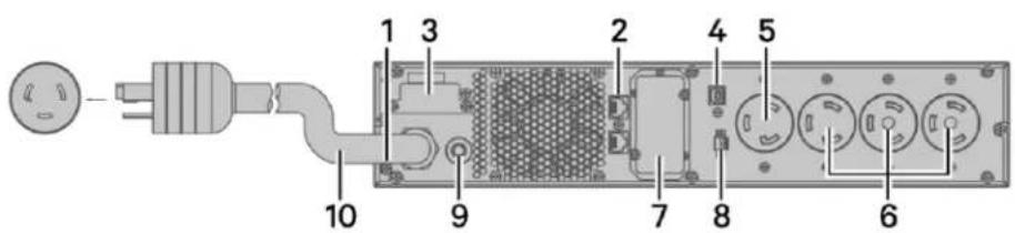
Figure 1-1 Liebert® PSI5-800/1100/1500RT120, PSI5-1500RT120TAA & PSI5-1500RT120LI Rear Panel

text_image
1 2 3 4 5 6 7 8 9 10ITEM DESCRIPTION
| 1 Grounding Screw for Network/Fax/Modem Surge Protection Input/Ouptut (Torque = 7 lbf-in) | |
| 2 Network/Fax/Modem Surge Protection Input/Output | |
| 3 External Battery Connector (not applicable on LI models) | |
| 4 USB Port | |
| 5 Programmable Receptacles | |
| 6 Non-Programmable Receptacles | |
| 7 IntelliSlot Port | |
| 8 Emergency Power Off (EPO) Connector | |
| 9 Input Circuit Breaker (10A, 13A, 16A for 800RT, 1100RT, 1500RT models respectively) | |
| 10 AC Input | |
Figure 1-2 Liebert® PSI5-2200RT120, PSI5-2200RT120TAA & PSI5-2200RT120LI Rear Panel

text_image
1 3 2 4 5 10 9 7 8 6ITEM DESCRIPTION
| 1 Grounding Screw for Network/Fax/Modem Surge Protection Input/Ouptut (Torque = 7 lbf-in) | |
| 2 Network/Fax/Modem Surge Protection Input/Output | |
| 3 External Battery Connector (not applicable on LI models) | |
| 4 USB Port | |
| 5 Programmable Receptacles | |
| 6 Non-Programmable Receptacles | |
| 7 IntelliSlot Port | |
| 8 Emergency Power Off (EPO) Connector | |
| 9 Input Circuit Breaker (20A) | |
| 10 AC Input | |
Figure 1-3 Liebert® PSI5-3000RT120, PSI5-3000RT120TAA & PSI5-3000RT120LI Rear Panel

text_image
1 3 2 4 11 5 10 9 7 8 6ITEM DESCRIPTION
| 1 Grounding Screw for Network/Fax/Modem Surge Protection Input/Ouptut (Torque = 7 lbf-in) | |
| 2 Network/Fax/Modem Surge Protection Input/Output | |
| 3 External Battery Connector (not applicable on LI models) | |
| 4 USB Port | |
| 5 Programmable Receptacles | |
| 6 Non-Programmable Receptacles | |
| 7 IntelliSlot Port | |
| 8 Emergency Power Off (EPO) Connector | |
| 9 Input Circuit Breaker (30A) | |
| 10 AC Input | |
| 11 Output Circuit Breaker | |
Figure 1-4 Liebert® PSI5-5000RT208 Rear Panel
text_image
1 3 2 4 5 10 9 7 8 6ITEM DESCRIPTION
| 1 Grounding Screw for Network/Fax/Modem Surge Protection Input/Ouptut (Torque = 7 lbf-in) | |
| 2 Network/Fax/Modem Surge Protection Input/Output | |
| 3 External Battery Connector | |
| 4 USB Port | |
| 5 Programmable Receptacles | |
| 6 Non-Programmable Receptacles | |
| 7 IntelliSlot Port | |
| 8 Emergency Power Off (EPO) Connector | |
| 9 Input Circuit Breaker (30A) | |
| 10 AC Input | |
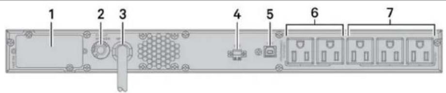
Figure 1-5 Liebert® PSI5-1000/1500RM1201U Rear Panel
text_image
1 2 3 4 5 6 7ITEM DESCRIPTION
| 1 IntelliSlot Port | |
| 2 Input Circuit Breaker (13A, 16A for 1000RM and 1500RM models respectively) | |
| 3 AC Input | |
| 4 Emergency Power Off (EPO) Connector | |
| 5 USB Port | |
| 6 Programmable Receptacles | |
| 7 Non-Programmable Receptacles | |
Figure 1-6 Liebert® PSI5 Mini Tower Rear Panels

text_image
1 4 6 12 10 7 11 5 8 9
text_image
Labeled diagram of a server rack with numbered components and internal connectors
text_image
3 4 6 12 10 8 11 5 7 9ITEM DESCRIPTION
| 1 PSI5-750/1100MT120 | |
| 2 PSI5-1500MT120 | |
| 3 PSI5-1500MT120LI | |
| 4 Network/Fax/Modem Surge Protection Input/Output | |
| 5 Grounding Screw for Network/Fax/Modem Surge Protection Input/Ouptut (Torque = 7 lbf-in) | |
| 6 IntelliSlot Port | |
| 7 Non-Programmable Receptacles | |
| 8 Programmable Receptacles | |
| 9 AC Input | |
| 10 USB Port | |
| 11 AC Input Breaker (10A, 13A, 16A for 750MT, 1100MT, 1500MT models respectively) | |
| 12 Emergency Power Off (EPO) Connector | |
1.3 Front Panel
NOTE: For detailed descriptions of the LCD, see Display Panel Indicators on page 19.
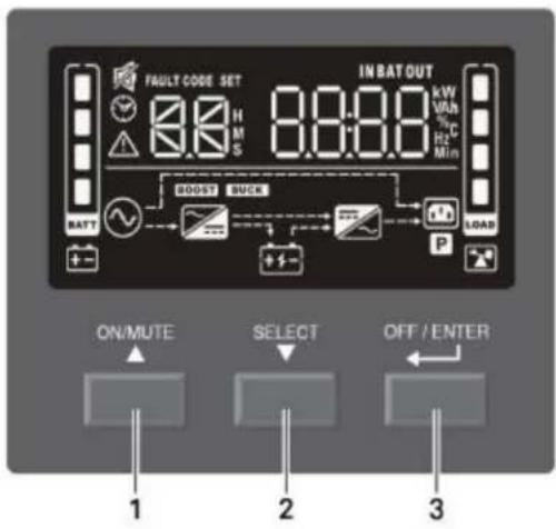
Figure 1-7 Controls and Display on 2U and MT Models
text_image
FAULT CODE SET 8:0 H M S IN BAT OUT kW VHz % C Hz Min BATT BOOST SUCK P LOAD ON/MUTE SELECT OFF / ENTER 1 2 3| ITEM DESCRIPTION | |
| 1 ON/MUTE button. See Controls on page 18, for details. | |
| 2 | SELECT button. See Controls on page 18, for details. |
| 3 OFF/ENTER button. See Controls on page 18, for details. | |
Figure 1-8 Controls and Display on 1U Models
text_image
ON/MUTE SELECT OFF/ENTER 1 2 3 FUST CODE SET YEAR DATE TIME INPUT OUTOFF 0.0000 0.0000 0.0000 FCTG CVCF OKITEM DESCRIPTION
| 1 ON/MUTE button. See Controls on page 18, for details. | |
| 2 | SELECT button. See Controls on page 18, for details. |
| 3 OFF/ENTER button. See Controls on page 18, for details. | |
This page is intentionally left blank.
2 Installation
2.1 What's Included
RT models
- UPS
-
Accessory box including
-
Quick installation guide
• Safety and regulatory statements - Front bezel
- 4 x Tower feet and screws (M4 x 8 mm)
- 2 x UPS rack ears
- 8 x Rack ear screws (M4 x 8 mm)
- USB type A to B cable
- Rail slide kit box
- Left and right rail set
- 8 x Rail kit screws (M6 x 12 mm)
- 4 x Fixing studs (∅8.5 mm x 15.5 mm)
- 6 x Rack nuts (M6)
• NEMA L5-20R to 5-20P adapter cord (2200RT models only)
RM models:
- UPS
-
Accessory box including:
-
Quick installation guide
- Safety Instructions
- 2 x UPS rack ears
- 8 x Rack ear screws (M4 x 8mm)
- USB type A to B cable
- Rail slide kit box
- Left and right rail set
- 8 x Rack kit screws (M6 x 12mm)
- 4 x Fixing studs (∅8.5mm x 15.5mm)
- 6 x Rack nuts (M6)
MT models
- UPS
- Quick installation guide
• Safety and regulatory statements - USB type A to B cable
2.2 Unpacking and Inspection
Unpack the UPS and conduct the following checks:
- Inspect the UPS for shipping damage. If any shipping damage is found, report it to the carrier and your local dealer or your Vertiv™ representative immediately.
- Check the accessories included in the packing list. If there is any discrepancy, contact your local dealer or Vertiv representative immediately.
2.3 Preparation for installation
2.3.1 Installation Environment
- Install the UPS indoors in a controlled environment where it cannot be accidentally turned off. The installation environment should meet the conditions listed Specifications on page 31.
- Place it in an area of unrestricted airflow around the unit, away from water, flammable liquids, gases, corrosives and conductive contaminants. Avoid direct sunlight.
- The socket outlet should be nearby and easily accessible.
NOTE: Operating the UPS in temperatures above 77°F (25°C) reduces battery life.
2.3.2 Installation Clearances
Maintain at least 4 in. (100 mm) clearance in the front and rear. Do not obstruct the air inlets on the front panel and rear panel. Blocking the air inlets reduces ventilation and heat dissipation, shortening the service life of the UPS.
2.4 Installing the UPS
2.4.1 Installing a 2U Model
The 2U UPS and optional battery cabinets may be installed in a tower or rack configuration. The 2ULI models may also be installed in a tower or rack configuration but do not support external battery cabinets. Determine the configuration that meets your application needs, see Tower Installation below, or Rack-Mount Installation on the facing page.
Tower Installation
When using the UPS in a tower configuration, see Figure 2-1 below. If you have an external battery, see Figure 2-2.
Figure 2-1 Attaching stands to the UPS

natural_image
Diagram of a server rack with an attached drive unit (no text or symbols)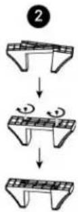
natural_image
Illustration of a server tower with control panel and base mount (no text or symbols)
text_image
4 70 mm 70 mmITEM DESCRIPTION
| 1 Rotate the display by pulling out, and turning it clockwise until it is seated in the proper orientation. |
| 2 Connect the two halves of the stand together. |
| 3 Place the UPS in the stands. |
| 4 Make sure that the stands are installed 70mm (2.76 in.) form the edge of the unit. |
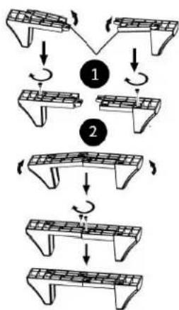
Figure 2-2 Attaching stands to the UPS and external battery
flowchart
graph TD
    A["Step 1: Panel arrangement"] --> B["Step 2: Retraction"]
    B --> C["Step 3: Panel structure with rotation arrows"]
    C --> D["Step 4: Retraction with rotation arrow"]
    D --> E["Step 5: Panel structure with rotation arrow"]

natural_image
Line drawing of a server rack unit with two front-mounted units and a control panel (no text or symbols)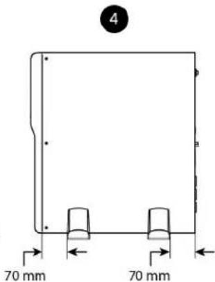
text_image
4 70 mm 70 mmITEM DESCRIPTION
| 1 Insert a spacer on each stand and install the securing screws. | |
| 2 Connect the two halves of the stand together and install the securing screws | |
| 3 | Place the UPS and external battery pack in the stands (rotate the display on the UPS if desired, see Figure 2-1) |
| 4 Make sure that the stands are installed 70 mm (2.76 in.) from the edge of the unit. | |
Rack-Mount Installation

CAUTION: Do not use the mounting brackets to lift the unit. Use the mounting brackets only to secure the UPS to the rack.
See Figure 2-3 to install the unit in a rack. If you have an external battery, see Figure 2-4.
Figure 2-3 Installing the UPS in a rack
flowchart
graph TD
    A["1: Rack ear"] --> B["2: Fixing stud"]
    B --> C["3: Rail kit screw"]
    C --> D["4: Rack nuts"]
    D --> E["5: Rail kit screw"]
    E --> F["6: Rail kit screw"]
| ITEM DESCRIPTION | |
| 1 Attach the rack ears with four rack ear screws to the front right and left sides of the UPS | |
| 2 | Attach two fixing studs to each rail. Select the desired U position and position the rails onto the rack using the fixing studs. |
| 3 Attach two rail kit screws to each rail to secure the rails to the rack. | |
| 4 Attach three rack nuts on each side of the rack | |
| 5 | Place the UPS with attached rack ears onto the rail supports. The batteries may be temporarily removed for easier installation. |
| 6 Attach two rail kit screws to each UPS rack ear and corresponding rack nut to secure the UPS to the rack. | |
Figure 2-4 Installing the external battery in a rack
text_image
Technical diagram illustrating six stages of rail installation with labeled components such as rack, fixing stud, and screw.| ITEM DESCRIPTION | |
| 1 Attach the rack ears with four rack ear screws to the front right and left sides of the external battery. | |
| 2 | Attach two fixing studs to each rail. Select the desired U position and position the rails onto the rack using the fixing studs. |
| 3 Attach two rail kit screws to each rail to secure the rails to the rack. | |
| 4 Attach three rack nuts on each side of the rack. | |
| 5 Place the external battery with attached rack ears onto the rail supports. | |
| 6 | Attach two rail kit screws to each external battery kit rack ear and corresponding rack nut to secure the external battery to the rack. |
2.4.2 Installing a 1U Model

CAUTION: Do not use the mounting brackets to lift the unit. Use the mounting brackets only to secure the UPS to the rack.
See Figure 2-5 below to install the unit.
Figure 2-5 Installing the UPS in a rack
text_image
Technical diagram illustrating six different rail installation methods for a structural assembly, showing rack and fixed stud components with screw placements.| ITEM DESCRIPTION | |
| 1 Attach the rack ears with four rack ear screws to the front right and left sides of the UPS | |
| 2 | Attach two fixing studs to each rail. Select the desired U position and position the rails onto the rack using the fixing studs |
| 3 Attach two rail kit screws to each rail to secure the rails to the rack | |
| 4 Attach rack nuts on each side of the rack | |
| 5 | Place the UPS with attached rack ears onto the rail supports. The batteries may be temporarily removed for easier installation. |
| 6 Attach a rail kit screw to each UPS rack ear and corresponding rack nut to secure the UPS to the rack | |
2.4.3 Installing a Mini Tower (MT) Model
Place the unit upright, on its feet without blocking air inlets.
2.5 Connecting Loads
The UPS has non-programmable and programmable outlets. Plug your critical equipment (such as computer, monitors, etc.) into the non-programmable outlets and your less-critical equipment (such as printers and other less-often used peripherals) into the programmable outlets. Refer to setting numbers 2 and 3 in Table 3-6 for programming instructions.
2.6 Connecting for Network Protection (Optional)
Protection from electrical surges to your computer network or telephone is provided on 2U and MT models. Use the network/fax/modem surge-protection ports on the rear panel. Connect the "IN" port to the line from the wall jack and the "OUT" port to your device port. Use of this feature is not required for proper operation of the UPS.
2.7 USB Connection
Basic monitoring of the PSI5 ^™ and unattended controlled shutdown of your computer in case of a power failure can be done using the Liebert Power Assist software via the USB port. Visit www. vertiv.com/ powerassist for additional information.
2.8 Emergency Power Off (EPO) Connection (Optional)
To comply with national and local wiring codes and regulations, the EPO connector internally disconnects all power sources to equipment connected to the UPS. The default operation is “active open” which means you must remove the factory-installed jumper and connect to external contacts that are normally closed but which open during a power-off event. The logic may be reversed in the Settings; see Configuring UPS with the Settings Menu on page 23. If you do not use the EPO connector, leave the factory-installed jumper in place and the default EPO settings in the Settings.
2.9 External Battery Cabinet Connection on 2U Models (Optional)
External battery cabinets provide longer battery run time for connected devices. Refer to Specifications on page 31, and Run Times on page 38, to select the appropriate model and quantity for your PSI5 model and applications. You can connect up to six battery cabinets to the 2U PSI5 models. LI, MT, and 1U models do not support external battery cabinets.
To connect an external battery pack:
- Connect one end of the external battery cable to the UPS and one end to the battery cabinet as shown in Figure 2-6 on the facing page.
- If connecting more than one external battery, connect one end of the external battery cable to the second connector on the battery cabinet, the connect the other end to the next battery cabinet as shown in Figure 2-6 on the facing page.
NOTE: After installation and initial startup, set the number of installed battery cabinets in the UPS Settings.
NOTE: When two or more external battery cabinets are used with PSI5-1100/2200/3000/5000 models, the UPS load rating is decreased by 20%.
Figure 2-6 Connecting External Batteries

flowchart
graph TD
    A["Server Rack"] -->|1| B["Network Switch"]
    A -->|2| C["Device Layout"]
    A -->|3| D["Device Layout"]
    A -->|4| E["Device Layout"]
| ITEM DESCRIPTION | |
| 1 Connection to UPS | |
| 2 Connection from UPS to single/first external battery | |
| 3 Connection to second connector on external battery cabinet for additional battery cabinets. | |
| 4 Connect to next external battery |
2.10 Network Communication Card Connection (Optional)
Advanced monitoring and simple control of the PSI5 can be done with the use of a Vertiv Liebert IntelliSlot Unity Communications card. Visit www.vertiv.com/intellislot for additional information.
To install the card:
- Remove the two screws and protective cover on the rear panel network communications port.
- Insert the card into the port and secure it with the screws. Refer to the documentation with the card or at the link above for cable connection and operation.
2.11 Connecting AC Input

CAUTION: For 1U and MT UPS models, to reduce the risk of fire, connect only to a circuit provided with 20A maximum branch circuit over current protection in accordance with the National Electrical Code, ANSI/NFPA 70 and the Canadian Electrical Code, Part I, C22.1.
Ensure that all the loads are first powered off. Connect to an input power supply/wall outlet that is properly protected by a circuit breaker in accordance with national and local electrical codes. The input receptacle must be grounded. See Specifications on page 31, for input cord rating. An external circuit breaker as described in Table 2-1 below is recommended.
Once the UPS is plugged into the wall outlet, it begins charging the battery.
NOTE: While every precaution has been taken to ensure that the battery is in good condition, Vertiv™ recommends plugging the UPS into AC input and to charge the battery for at least 12 hours prior to providing full backup time protection for any utility power abnormality.
Table 2-1 Recommended external circuit breaker
| WIRING | |
| MODEL RECOMMENDED EXTERNAL BREAKER | |
| PSI5-750MT120 | 15A |
| PSI5-800RT120 | |
| PSI5-1100RM1201U | |
| PSI5-1100MT120 | |
| PSI5-1100RT120 | |
| PSI5-1500RM1201U | |
| PSI5-1500RT120 | |
| PSI5-1500RT120TAA | |
| PSI5-1500MT120 | |
| PSI5-1500MT120LI | |
| PSI5-2200RT120 | 20APSI5-2200RT120TAA |
| PSI5-2200RT120LI | |
| PSI5-3000RT120TAA | 30A |
| PSI5-3000RT120LI | |
| PSI5-3000RT120 | |
| PSI5-5000RT208 | |
3 Operation
3.1 Modes of Operation
3.1.1 Off Mode
The UPS input is plugged into a stable, nominal source, but the outlets are turned off. The internal batteries are charging.
3.1.2 On/Normal Mode
The UPS input is plugged into a stable, nominal source, and the outlets are turned on. The internal batteries are charging.
3.1.3 On/Automatic Voltage Regulation (AVR)/Boost Mode
The UPS input is plugged in, but the voltage source is abnormally low (brown-out). The UPS automatically corrects the low voltage and allows the outlets to be on with the normal, expected voltage. The internal batteries are charging.
3.1.4 On/Automatic Voltage Regulation (AVR)/Buck Mode
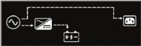
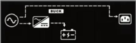
The UPS input is plugged in, but the voltage source is abnormally high. The UPS automatically corrects the high voltage and allows the outlets to be on with the normal, expected voltage. The internal batteries are charging.
3.1.5 On/Battery Mode
The UPS input is not plugged in or the voltage source has become extremely low or high and unusable. The UPS automatically switches to the internal battery to provide normal, usable voltage to the outlets.
3.1.6 Fault Mode
An error or fault condition has occurred. The outlets are shut off.
3.1.7 Battery Self-Test Mode
The UPS enters a cycle of approximately 10 seconds during which it tests the internal battery. The outlets are still temporarily powered by the internal battery. Self-test mode occurs at the following instances:
- At startup when turning the UPS on.
• Automatically every 8 weeks as a self-check. - Manually by pressing and holding the ON/Mute button for 3 seconds when the unit is on.
3.1.8 Controls
Figure 3-1 Display and Buttons on the front panel of 2U and MT units
text_image
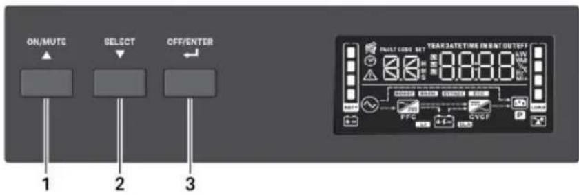
FAULT CODE SET 8.8 H M S 8:00 IN BAT OUT kW Vah % C Min BOOST BUCK BATT P LOAD ON/MUTE SELECT OFF / ENTER 1 2 3Figure 3-2 Display and Buttons on the front panel of 1U units

text_image
ON/MUTE SELECT OFF/ENTER 1 2 3 YEAR DATE: WE IS NAT OUTOFF 0.000 0.000 0.000 PULF CODE SET ELECTRICAL DATA CNC PVC + - + - + - + - + - + - + - + - + - + - + - + - + - + - + - + - + - + - + - + - + - + - + - + -Table 3-1 PSI5 Button Description
| ITEM DESCRIPTION | |
| 1 | ON/MUTE Button.Turn UPS on: When in Off mode, press and hold for 2 seconds to enter Battery Self-Test mode, then On mode.Manual Battery Self-Check: When in On mode, press and hold for 3 seconds to temporarily enter Battery Self-Test mode.Mute: When in On/Battery mode, press and hold for 3 secondsSettings Menu UP: When in the Settings Menu, press to cycle up through options; See Configuring UPS with the Settings Menu on page 23. |
| 2 | SELECT Button.Select: Press to cycle through the operating parametersSettings Menu: When in Off mode, press and hold for 3 seconds to enter the Settings MenuSettings Menu Down: When in Settings Menu, press to cycle down through setting options, See Configuring UPS with the Settings Menu on page 23. |
| 3 | OFF/ENTER Button.UPS Off: When in On mode, press and hold for 2 seconds to enter Off mode.Settings Menu Enter: When in the Settings Menu, press and hold to enter setting option, press and hold again to return to setting number. See Configuring UPS with the Settings Menu on page 23. |
3.2 Display Panel Indicators
NOTE: The display automatically powers off to conserve power. Press any button quickly to wake the display.
Figure 3-1 on page 18, shows the LCD on the front panel of the UPS.
Table 3-2 Display icons, sections and functions
| ICONS AND DISPLAY DESCRIPTION | ||
 | Off mode | |
 | On/Normal mode | |
 | On/AVR/Boost mode | |
 | On/AVR/Buck mode | |
 | On/Battery mode | |
 | Estimated backup time in H (hours). M (minutes), or S (seconds) | |
 | Indicates warning and fault codes. See Faults on page 22, and Warnings on page 21. | |
 | Displays various UPS operation parameters. | |
| ICONS AND DISPLAY DESCRIPTION | ||
 | Settings menu. See Configuring UPS with the Settings Menu on page 23. | |
 | Audible On/Battery mode alarm silenced | |
 | UPS output load in 25% increments | |
 | Battery level in 25% increments | |
 | Low battery | |
 | Overload icon | |
 | Programmable outlet icon | |
 | Battery icon | |
 | Battery charging icon | |
3.3 Audible-Tone Indicators
Table 3-3 Tones and Beeps of the UPS
| TYPE INDICATES | |
| 1 beep every 10 seconds Battery mode | |
| 1 beep every second Overload warning | |
| 1 beep every 2 seconds | Low-battery warning |
| Other warning | |
| Constant, solid tone Fault | |
| 1 beep | Power On |
| Battery self-test | |
| Button press | |
| 1 long tone Power off | |
3.4 Warnings
The UPS has early warning indicators that allow the UPS to function normally for a short period before the outputs are shut off.
Table 3-4 Warning Indicators and Actions
| ITEM DESCRIPTION TROUBLESHOOTING | ||
 | Battery low | Charge the UPS battery for at least 12 hours or replace the battery; seeReplacing the UPS Batteries on page 27. |
 | Overload | Reduce the load to below the rating indicated in theSpecificationson page 31. |
 | Site wiring fault | Turn of the UPS and call an electrician to correct the wiring. Possible causes are that the line and neutral are reversed or that there is no ground conductor. |
 | Over temperature Call VertivTMcustomer support, 1-800-222-5877. | |
 | Charger failure Call VertivTMcustomer support, 1-800-222-5877. | |
 | Battery fault | Charge the UPS battery for at least 12 hours or replace the battery; seeReplacing the UPS Batteries on page 27. |
| ITEM DESCRIPTION TROUBLESHOOTING | ||
 | Battery replacement | Charge the UPS battery for at least 12 hours or replace the battery; seeReplacing the UPS Batteries on page 27. |
 | EEPROM error Call Vertiv | TMcustomer support, 1-800-222-5877. |
 | Internal battery is not connected | Check the connection of the battery, seeReplacing the UPS Batteries on page 27. |
 | Over charge Call Vertiv | TMcustomer support, 1-800-222-5877. |
 | Emergency Power Off activated | Remove the EPO state on the EPO connector.NOTE: Output Immediately shuts off when the EPO warning occurs. |
3.5 Faults
The UPS displays fault codes when it detects a problem and automatically shuts off output power.
Table 3-5 Fault Codes and Actions
| CODE DESCRIPTION TROUBLESHOOTING | ||
| 01 Bus start fail | Call VertivTM customer support, 1-800-222-5877. | |
| 02 Bus over | ||
| 03 Bus under | ||
| 11 Inverter soft start fail | ||
| 12 Inverter voltage high | Turn Off the UPS, disconnect all connected loads and restart the UPS. If the fault is still active, call Vertiv customer support, 1-800-222-5877. If the fault is no longer active, plug each piece of equipment in one at a time to locate the device that has the short circuit | |
| 13 Inverter voltage low | ||
| 14 Inverter output short | ||
| 27 | Battery voltage too high | Replace the battery or call VertivTM customer support, 1-800-222-5877. |
| 28 Battery voltage too low | ||
| 41 Over temperature | Make sure that the air temperature is within the range listed in Specifications on page 31. Otherwise, call VertivTM customer support, 1-800-222-5877. | |
| 43 Overload | Reduce the load to below the UPS rating listed in Specifications on page 31, and restart the UPS. | |
| 45 Charger failure Call Vertiv | TM customer support, 1-800-222-5877. | |
3.6 Normal Startup
- With the UPS connected to AC input Press and hold the ON/MUTE button for 2 seconds.
The UPS is in Battery Self-Test mode for 10 seconds. After a successful self-test, the UPS is on.
3.7 Normal Shutdown
- Press and hold the power button for 2 seconds. The outlets are turned off.
- Disconnect AC input power.
3.8 Full Shutdown
- Press and hold the power button for 2 seconds. The outlets are turned off.
- Disconnect AC input power
- Remove the front bezel, disconnect the battery connector and replace the front bezel. The unit is fully shut down.
3.9 Configuring UPS with the Settings Menu
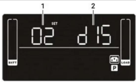
You may adjust several settings to configure the UPS to operate with your equipment In Settings mode, the UPS displays two parameter fields (see Figure 3-3 below) The first selects the setting option to configure and the second lists the selectable parameters for each setting option. Table 3-6 describes the setting options. In addition, symbols relevant to the setting option may be shown. The symbols are described in Table 3-2 on page 19.
Figure 3-3 UPS Display In Setting Mode
text_image
1 SET 02 d 15 BATT LOAD P| ITEM DESCRIPTION |
| 1 Setting option number |
| 2 Setting parameter |
To access Settings mode and adjust settings:
- Power off the UPS by pressing the OFF/Enter button for at least 2 seconds.
- Press and hold the Select button for 3 seconds. Settings mode displays; see Figure 3-3 above.
- Use the up/down arrow buttons to display the number of the setting function to adjust, then press OFF/Enter See Table 3-6 on the facing page, for the options.
- Use the up/down arrow buttons to select the setting, then press OFF/Enter. See Table 3-6 for the settings.
- When finished, select setting option 00, and press OFF/Enter to exit Settings mode.
Table 3-6 Setting Numbers and Options
| SETTING NUMBER SETTING OPTIONS | |
| 01 | Nominal voltage setting. Set the nominal system voltage to match the input voltage of the UPS. This setting affects the buck/boost/on-battery transfer points and sets the output voltage in Battery mode.For 120 VAC models:100 = 100VAC110 = 110VAC115 = 115VAC120 = 120VAC (default)125 = 125VACFor 208 VAC models200 = 200VAC208 = 208VAC (default)240 = 240VAC |
| 02 | Enable/Disable programmable outlets.ENA = Enable, programmable outlets are powered when running on battery per the time assigned in setting 3.DIS = Disable (default), programmable outlets are powered when running on battery until battery end of discharge. |
| 03 | Programmable outlets time limit with setting 2 enabled. Set a maximum time the programmable outlets are powered when running on battery. Setting a shorter time limit for programmable outlets extends the time the non-programmable outlets are powered when running on batteryO to 999 minutes (999 is default) |
| 04 | Enable/Disable site fault detection.ENA = Enable (default)DIS = Disable |
| 05 | Enable/Disable neutral grounding in battery modeENA = Enable (default)DIS = Disable |
| 06 | Battery backup time limit. Sets a maximum time to provide output when running on battery.O to 999 = minutes, selecting 0 (zero) sets a limit of 10 seconds.DIS = Disable Backup time depends on battery capacity (default) |
| 07 | Set the number of connected external battery cabinets. (available only on VRLA 2U models)O to 6 (0 is default)NOTE: For the Liebert PSI5-1100/2200/3000/5000: When using two or more external battery cabinets (EBCs) the UPS load rating will be decreased by 20%. The % load graph on the LCD automatically adjusts to reflect this derating. |
| 08(11 on TAA models) | Set the Emergency Power Off (EPO) logic function.AO = Active Open (default)Activates Emergency Power Off when EPO connector pins are not jumpered (open).AC =Active CloseActivates Emergency Power Off when EPO connector pins are jumpered (closed). |
SETTING NUMBER SETTING OPTIONS
| 09(12 on TAA models) | Set the sensitivity of acceptable input voltage quality. When distortion or disturbances are detected on the input voltage, the UPS protects the plugged-in equipment by switching to Battery mode. The lower the sensitivity setting, the less frequently the UPS switches to battery, but the more distortion and noise may be passed through to the plugged-in equipment. If you are using a poor quality input source such as a generator or step-wave source on which your equipment can fully operate, a lower sensitivity setting may provide longer battery life and run times.ST1 - High sensitivity (default). Provides the maximum protection. The transfer time is typically 4 to 6 ms, 10ms max.ST2 - Medium sensitivity. Provides medium protection. The transfer is typically 6 to 8 ms, 11 ms max.ST3 - Low sensitivity. Provides the least protection but may provide longer battery life and run time for tolerant equipment. The transfer time is typically 8 to 10 ms, 13 ms max. |
| 13(Only available on TAA models) | Resets the UPS Power On Counter to 0. This counts the number of times the UPS has been powered on since the first startup or the last time it was reset.YES - Reset the counter to 0NO - Do not reset to 0 and return to setting selection |
| 14(Only available on TAA models) | Resets all UPS Settings to their factory defaults.YES - Reset to factory default settingsNO - Do not reset to factory defaults and return to setting selection |
| 00 Exit Settings mode. |
This page is intentionally left blank.
4 Maintenance and Battery Replacement
4.1 Precautions
Although the Liebert ^® PSI5 is designed and manufactured to ensure personal safety, improper use can result in electrical shock or fire. To ensure safety, observe the following precautions:
- Turn off and unplug the UPS before cleaning it.
- Clean the UPS with a dry cloth. Do not use liquid or aerosol cleaners.
- Never block or insert any objects into the ventilation holes or other openings of the UPS.
- Do not place the UPS power cord where it might be damaged.
4.2 Battery Charging
The batteries are valve-regulated, non-spillable, lead-acid in all models except for the LI, which uses LiFePO4 type lithium-ion batteries. In all cases, the batteries should be kept charged to retain their design life. The PSI5 charges the batteries continuously when it is connected to input power. If the PSI5 will be stored for a long time, Vertiv™ recommends connecting the UPS to input power every 4 to 6 months for at least 2 hours for LI models and 24 hours for lead acid models to ensure full recharge of the batteries.
The Lithium Ion batteries used in the PSI5 LI series, as well as all Vertiv Lithium-Ion UPSs, contain a Battery Management System (BMS) that self-monitors the safety of the LI batteries in real-time. This is an agency tested and certified requirement now eliminating the industry wide safety risk known with previous Li-Ion batteries.
4.3 Replacing the UPS Batteries
IMPORTANT! Before you proceed, please review the battery safety precautions available at https://www.vertiv.com/ComplianceRegulatoryInfo
You may safely replace the internal battery pack. See the Specifications on page 31, for the part number of the replacement battery for your UPS model number.
NOTE: Replace the battery with the same type and number as originally installed.
NOTE: The internal battery pack is hot-swappable. However, caution should be exercised because during this procedure the load is unprotected from disturbances and power outages. Do not replace the battery while the UPS is operating in Battery Mode. This will result in a loss of output power and will drop the connected load.
To replace the batteries on 1U and 2U models:
- Remove the front bezel by pulling firmly until the snaps release.
- Disconnect the battery connector by squeezing the ends and gently pulling the two pieces apart.
- Remove the two screws and the metal battery cover plate.
-
Slide out the existing battery kit.
-
For LI models: Attach the provided connector to the replacement battery terminals. Plug the black wire in first then the red. For VRLA models: skip this step.
- Orient the connector and the new battery in the same way as the original battery and slide into UPS.
- Reconnect the two halves of the battery connector and slide the front panel back on until it clicks.
- Replace the metal plate and secure with the two screws.
- Snap the front bezel back on.
- Press and hold the power button for 3 seconds to initiate the Battery-Self Check mode clearing any previous battery fault warning.
- Properly dispose of the old batteries at an appropriate recycling facility or return them to Vertiv™ in the packing material from the new batteries.
Figure 4-1 Removing the battery box from 2U units to replace batteries

flowchart
graph TD
    A["1 Server"] --> B["2 Server"]
    B --> C["3 Server"]
    C --> D["4 Storage Unit"]
    D --> E["Internal Device"]
    style A fill:#f9f,stroke:#333
    style B fill:#f9f,stroke:#333
    style C fill:#f9f,stroke:#333
    style D fill:#f9f,stroke:#333
    style E fill:#f9f,stroke:#333
ITEM DESCRIPTION
| 1 Remove the front panel from the UPS. | |
| 2 Disconnect the battery connector by squeezing the ends of the connectors and pulling apart. | |
| 3 Remove the 2 screws on the front panel of the battery box, and pull out the battery box. | |
| 4 | For LI models: attach the provided connector to the replacement battery terminals. Plug the black wire in first then the red.For VRLA models: Skip this step |
| 5 Place the battery box in the UPS, and re-install the front panel of the battery box. | |
| 6 Connect the battery wires. | |
| 7 Replace the front panel on the UPS. | |
Figure 4-2 Removing the battery box from 1U units to replace batteries
flowchart
graph TD
    A["1: File Load"] --> B["2: Display Panel"]
    B --> C["3: Storage Panel"]
    C --> D["4: Package Box"]
    D --> E["5: Storage Module"]
    E --> F["6: Display Panel"]
    F --> G["7: Package Box"]
| ITEM DESCRIPTION | |
| 1 Remove the front panel. | |
| 2 Disconnect the battery connector by squeezing the ends of the connectors and pulling apart. | |
| 3 Remove screws and metal battery cover. | |
| 4 Remove the battery | |
| 5 | Slide the replacement battery kit into the UPS. Replace the metal plate and secure with the two screws. |
| 6 Reconnect the battery connector. | |
| 7 Snap the front panel back on. | |
To replace the batteries on MT models:
- Place the unit on its left side and remove the 6 screws and the metal battery cover plate.
- Slide out the existing battery kit and disconnect the two halves of the battery connector.
- For LI models: attach the provided connector to the replacement battery terminals. Plug the black wire in first then the red. For VRLA models: skip this step.
- Orient the connector and the new battery in the same way as the original battery, connect the two halves of the battery connector, and slide into UPS.
- Replace the metal plate and secure with the 6 screws.
- Press and hold the power button for 3 seconds to initiate the Battery-Self Check mode clearing any previous battery fault warning.
- Properly dispose of the old batteries at an appropriate recycling facility or return them to Vertiv™ in the packing material from the new batteries.
Figure 4-3 Replacing the batteries on MT models
flowchart
graph TD
    A["1: Display with ports and indicator"] --> B["2: Display with internal components"]
    B --> C["3: Display with internal components"]
    C --> D["4: Panel with internal structure"]
    D --> E["5: Display with internal components"]
    E --> F["6: Component insertion"]
    F --> G["7: Display with internal components"]
ITEM DESCRIPTION
| 1 With unit laying on left side, remove screws from battery cover. |
| 2 Remove the battery cover. |
| 3 Slide out the battery kit and disconnect the battery connector. |
| 4 Connect the battery connector to the replacement battery. |
| 5 Slide the replacement battery kit into the UPS. |
| 6 Replace the battery cover. |
| 7 Secure the battery cover with the screws. |
5 Specifications
Table 5-1 PSI5 Specifications for VRLA 2U Models
| MODEL PSI5-800RT120 | PSI5-1100RT120 | PSI5-1500RT120 / PSI5-1500RT-120TAA | PSI5-2200RT120 / PSI5-2200RT-120TAA | PSI5-3000RT120 / PSI5-3000RT-120TAA | PSI5-5000RT120 | |
| Power Rating | ||||||
| 125 VAC Input | 800 VA, 720 W, 6.4 A | 1100 VA, 990 W, 8.8 A | 1500 VA, 1350 W, 12 A | 1920 VA, 1920 W, 15.4 A | 3000 VA, 2700 W, 24 A | - |
| 120 VAC Input | 800 VA, 720 W, 6.7 A | 1100 VA, 990 W, 9.2 A | 1440 VA, 1350 W, 12 A | 1920 VA, 1920 W, 16 A | 2880 VA, 2700 W, 24 A | - |
| 115 VAC Input | 800 VA, 720 W, 7.0 A | 1100 VA, 990 W, 9.6 A | 1380 VA, 1350 W, 12 A | 1840 VA, 1840 W, 16 A | 2760 VA, 2700 W, 24 A | - |
| 110 VAC Input | 800 VA, 612 W, 6.2 A | 935 VA, 842 W, 8.5 A | 1275 VA, 1147 W, 11.6 A | 1632 VA, 1632 W, 14.8 A | 2550 VA, 2295 W, 23.2 A | - |
| 100 VAC Input | 800 VA, 612 W, 6.8 A | 935 VA, 842 W, 9.4 A | 1200 VA, 1147 W, 12 A | 1600 VA, 1600 W, 16 A | 2400 VA, 2400 W, 24 A | - |
| 240 VAC Input - - - - | 5000 VA, 4500 W, 20.8 A | |||||
| 230 VAC Input - - - - | 5000 VA, 4500 W, 21.7 A | |||||
| 220 VAC Input - - - - | 5000 VA, 4500 W, 22.7 A | |||||
| 208 VAC Input - - - - | 4250 VA, 3825 W, 20.4 A | |||||
| 200 VAC Input - - - - | 4250 VA, 3825 W, 21.3 A | |||||
| Dimensions and Weights | ||||||
| Unit Dimensions W x D x H (in) (mm) | 17.2 x 16.1 x 3.5(438 x 410 x 88) | 17.2 x 20.0 x 3.5(438 x 510 x 88) | 17.2 x 24.8 x 3.5(438 x 630 x 88) | |||
| Shipping Dimensions W x D x H (in) (mm) | 10.2 x 22.9 x 22.4(258 x 582 x 570) | 10.2 x 26.5 x 22.4(258 x 672 x 570) | 10.2 x 26.7 x 22.4(258 x 782 x 570) | |||
| Unit Weight, lb. (kg) | 29.3 (13.3) 31.1 (14.1) | 43.0 (19.5) 59.3 | (26.9) 71.4 (32.4) 81.0 | (36.7) | ||
| Shipping Weight, lb. (kg) | 41.7 (18.9) | 43.4 (19.7) | 56.0 (25.4) | 73.6 (33.4) | 85.8 (38.9) | 95.2 (43.2) |
| Input | ||||||
| Voltage Input Range(with battery operation) | 0 to 150 VAC | 0 to 300 VAC | ||||
| Voltage Input Range(without battery operation) | 75 to 146 VAC | 150 to 281 VAC | ||||
| Input Voltage Measurement Tolerance | ±3% | |||||
| Nominal Voltage Setting | 100 / 110 / 115 / 120 / 125 VAC | 200 / 208 / 220 / 230 / 240 VAC | ||||
| High Line Buck to Battery | 117 / 129 / 135 / 140 / 146 VAC | 234 / 243 / 257 / 269 / 281 VAC | ||||
| High Line Battery to Buck | 114 / 125 / 131 / 137 / 143 VAC | 228 / 237 / 251 / 262 / 274 VAC | ||||
| High Line Normal to Buck | 110 / 121 / 127 / 132 / 138 VAC | 220 / 229 / 242 / 253 / 264 VAC | ||||
| High Line Buck to Normal | 107 / 118 / 123 / 128 / 134 VAC | 214 / 223 / 235 / 246 / 257 VA | ||||
| Low Line Boost to Normal | 93 / 102 / 107 / 112 / 116 VAC | 186 / 193 / 205 / 214 / 223 VAC | ||||
| Low Line Normal to Boost | 90 / 99 / 104 / 108 / 113 VAC | 180 / 187 / 198 / 207 / 216 VAC | ||||
| Low Line Battery to Boost | 80 / 88 / 92 / 96 / 100 VAC | 160 / 166 / 176 / 184 / 192 VAC | ||||
| Low Line Boost to Battery | 75 / 83 / 86 / 90 / 94 VAC | 150 / 156 / 165 / 173 / 180 VAC | ||||
| Frequency Input Range | 55 to 65 Hz (57 to 63 Hz Battery to Normal comeback) | |||||
| Internal Rear Panel Input Breaker | 10 A 13 A 16 A 20 A 30 A | |||||
| Input Surge Protection | ANSI C6241 Category A, Level 3 1372J | EN6100-4-5, Level 3 2064J | ||||
| Input Power Cord NEMA 5-15P, offset 90-degree type (3 m attached) | NEMA L5-20P(3 m attached)NEMA L5-20 to 5-20P adapter cord (150 mm) | NEMA L5-30P(3 m attached) | NEMA L6-30P(3 m attached) | |||
| Output | ||||||
| Output Voltages(on battery) | 100 / 110/ 115 / 120 / 125 VAC (±1.5 on battery before alarm) user selectable(120 VAC is factory default) | 200 / 208 / 240VAC (±1.5 on battery before alarm) user selectable(208 VAC is factory default) | ||||
| Output Frequency(on battery) | 60 (default)/ 50 Hz ±1% | |||||
| Output Receptacles - not controllable | (3) NEMA 5-15R | (3) NEMA 5-15/20R,(1) NEMA L5-20R | (3) NEMA 5-15/20R,(1) NEMA L5-30R | (3) NEMA L6-30R | ||
| Output Receptacles - controllable | (3) NEMA 5-15R (3) NEMA 5-20R (1) NEMA L6-30R | |||||
| Transfer Time | Adjustable with User Setting09 ST1: 4-6 ms typical, 10 ms max. (default).ST2: 6-8 ms typical, 11 ms max.ST3: 8-10 ms typical, 13 ms max. | |||||
| Output Waveform(on battery) | Pure Sinewave | |||||
| Output Overload Operation | 100% — Alarm warning110% — Alarm warning and shutdown after 10 seconds120% — Alarm warning and immediate shutdown | |||||
| Protection Electronic | (overcurrent, short circuit w/ latching shutdown) | |||||
| AC Mode Efficiency | 96% for 100 / 110 / 115 / 120 / 125 VAC | |||||
| Buck and Boost Mode Efficiency | 93% for 100 / 110 / 115 / 120/ 125 VAC | |||||
| Recharge Time 6-8 hours to recover to 90% | ||||||
| Internal Battery | ||||||
| Part Number | PSI5-800BATKIT | PSI5-1100BATKIT | PSI5-1500BATKIT/PSI5-1500BATKITTAA | PSI5-2200BATKIT/PSI5-2200BATKITTAA | PSI5-3000BATKIT/PSI5-3000BATKITTAA | PSI5-5000BATKIT |
| Protection Electronic | (overcurrent, short circuit with latching shutdown) | |||||
| Type Valve-regulated | lead-acid (VRLA) in compliance with UL 1989 | |||||
| Quantity x Voltage x Ah | 2 x 12V x 9 Ah 2 | x 12V x 10 Ah 4 x | 12V x 9 Ah 6 x 12V | x 7 Ah 6 x 12V x 10 | Ah 6 x 12V x 10 Ah | |
| External Battery Cabinets | ||||||
| Model Number PSI5-24VBATT | PSI5-48VBATT/PSI5-48VBATTTAA | PSI5-72VBATT/PSI5-72VBATTTAA | ||||
| Protection Circuit Breaker | ||||||
| Type Valve-regulated | lead-acid (VRLA) in compliance with UL 1989 | |||||
| Quantity x Voltage x Ah | 2 x 12V x 9.0 Ah / 2 x 12V x 9.0 Ah | 4 x 12V x 9.0 Ah /4 x 12V x 9.0 Ah | 6 x 12V x 9.0 Ah / 6 x 12V x 9.0 Ah | |||
| Unit Dimensions W x D x H (in) (mm) | 17.2 x 16.1 x 3.5 (438 x 410 x 88) | 17.2 x 20 x 3.5(438 x 510 x 88) | 17.2 x 24.8 x 3.5 (438 x 630 x 88) | |||
| Shipping Dimensions W x D x H (in) (mm) | 10.2 x 22.9 x 21.7 (258 x 582 x 550) | 10.2 x 26.5 x 21.7(258 x 670 x 550) | 10.2 x 26.7 x 21.7 (258 x 782 x 550) | |||
| Unit Weight, lb. (kg) | 37.7 (17.1) | 63.9 (29.0) | 90.8 (41.2) | |||
| Shipping Weight, lb. (kg) | 51.8 (23.5) | 70.3 (31.9) | 96.1 (43.6) | |||
| Environmental Requirements | ||||||
| Operating Temperature °F (°C) | 32 to 104 (0 to 40) | |||||
| Operating Elevation, ft. (m) | 0 to 9,942 (0 to 3,000 without derating)Operating temperature reduced 9 °F (5 °C) for each additional 1,640ft. (500m) of altitude | |||||
| Relative Humidity | 20% to 90% non-condensing | |||||
| Storage Temperature °F (°C) | 5 to 122 (-15 to 50) | |||||
| Storage Relative Humidity | 10% to 90% non-condensing | |||||
| Audible Noise | <45 dB @ Line mode< 55 dB @ Battery mode | |||||
Table 5-2 PSI5 Specifications for VRLA 1U and MT Models
| MODEL PSI5-1000RM1201U PSI5-1500RM1201U PSI5-750MT120 PSI5-1100MT120 PSI5-1500MT120 | |||||
| Power Rating | |||||
| 125 VAC Input | 1000 VA, 900 W,8 A | 1500 VA, 1350 W,12 A | 750 VA, 675 W,6 A | 1100 VA, 990 W,8.8 A | 1500 VA, 1350 W,12 A |
| 120 VAC Input | 1000 VA, 900 W,8.3 A | 1440 VA, 1350 W,12 A | 750 VA, 675 W,6.3 A | 1100 VA, 990 W,92 A | 1440 VA, 1350 W,12 A |
| 115 VAC Input | 1000 VA, 900 W,8.7 A | 1380 VA, 1350 W,12 A | 750 VA, 675 W,6.5 A | 1100 VA, 990 W,9.6 A | 1380 VA, 1350 W,12 A |
| 110 VAC Input | 850 VA, 765 W,7.7 A | 1275 VA, 1147 W,11.6 A | 750 VA, 675 W,6.8 A | 935 VA, 842 W,8.5 A | 1275 VA, 1147 W,11.6 A |
| 100 VAC Input | 850 VA, 765 W,8.5 A | 1200 VA, 1147 W,12 A | 750 VA, 675 W,7.5 A | 935 VA, 842 W,9.4 A | 1200 VA, 1147 W,12 A |
| Dimensions and Weights | |||||
| Unit DimensionsW x D x H (in) (mm) | 17.2 x 18.9 x 1.7(438 x 480 x 44) | 17.2 x 23.6 x 1.7(438 x 600 x 44) | 5.7 x 14.8 x 8.7(145 x 370 x 220) | 5.7 x 18.9 x 8.7(145 x 480 x 220) | |
| Shipping DimensionsW x D x H (in) (mm) | 22.4 x 27.6 x 6.5(570 x 700 x 165) | 22.4 x 29.9 x 6.5(570 x 760 x 165) | 9.1 x 17.7 x 12.8(230 x 450 x 325) | 9.1 x 22.4 x 12.8(230 x 570 x 325) | |
| Unit Weight, lb. (kg) 36.4 (16.5) 45.6 (20.7) 24.7 (11.2) 26.0 (11.8) 40.1 (18.2) | |||||
| Shipping Weight,lb. (kg) | 42.3 (19.2) 52.2 (23.7) 27.8 (12.6) 29.1 (13.2) 44.1 (20.0) | ||||
| Input | |||||
| Voltage Input Range (withbatteryoperation) | 0 to 150 VAC | ||||
| Voltage Input Range(withoutbattery operation) | 75 to 146 VAC | ||||
| Input VoltageMeasurementTolerance | 3% | ||||
| Nominal Voltage Setting | 100 / 110 / 115 / 120 / 125 VAC | ||||
| High Line Buck to Battery | 117 / 129 / 135 / 140 / 146 VAC | ||||
| High Line Battery to Buck | 114 / 125 / 131 / 137 / 143 VAC | ||||
| High Line Normal to Buck | 110 / 121 / 127 / 132 / 138 VAC | ||||
| High Line Buck to Normal | 107 / 118 / 123 / 128 / 134 VAC | ||||
| Low Line Boost to Normal | 93 / 102 / 107 / 112 / 116 VAC | ||||
| Low Line Normal to Boost | 90 / 99 / 104 / 108 / 113 VAC | ||||
| Low Line Battery to Boost | 80 / 88 / 92 / 96 / 100 VAC | ||||
| Low Line Boost to Battery | 75 / 83 / 86 / 90 / 94 VAC | ||||
| Frequency Input Range | 55 to 65 Hz (57 to 63 Hz Battery to Normal comeback) | ||||
| Internal Rear Panel InputBreaker | 13 A | 16 A | 10 A | 13 A | 16 A |
| Input Surge Protection | ANSI C62.41 Category A, Level 3 1372J | ||||
| Input Power Cord | NEMA 5-15P, offset 90-degree type (3mattached) | NEMA 5-15P, offset 90-degree type (1.8m attached) | |||
| MODEL PSI5-1000RM1201U PSI5-1500RM1201U PSI5-750MT120 PSI5-1100MT120 PSI5-1500MT120 | |||||
| Output | |||||
| Output Voltages(on battery) | 100 / 110/ 115 / 120 / 125 VAC (±1.5 on battery before alarm) user selectable(120 VAC is factory default) | ||||
| Output Frequency(on battery) | 60 (default)/ 50 Hz ±1% | ||||
| Output Receptacles - notcontrollable | (3) NEMA 5-15R | ||||
| Output Receptacles -controllable | (2) NEMA 5-15R (3) NEMA 5-15R | ||||
| Transfer Time | Adjustable with User Setting 09ST1: 4-6 ms typical, 10 ms max. (default).ST2: 6-8 ms typical, 11 ms max.ST3: 8-10 ms typical, 13 ms max. | ||||
| Output Waveform(on battery) | Pure Sinewave | ||||
| Output OverloadOperation | 100% — Alarm warning110% — Alarm warning and shutdown after 10 seconds120% — Alarm warning and immediate shutdown | ||||
| Protection Electronic (overcurrent, short circuit w/ latching shutdown) | |||||
| AC Mode Efficiency 98% 96% | |||||
| Buck and Boost ModeEfficiency | 93% | ||||
| Recharge Time 6 hours to recover to 90% 6-8 hours to recover to 90% | |||||
| Internal Battery | |||||
| Part Number | PSI5-10001UBATKIT | PSI5-15001UBATKIT | PSI5-750MTBATKIT | PSI5-1100MTBATKIT | PSI5-1500MTBATKIT |
| Protection | Electronic (overcurrent, short circuit with latching shutdown) | ||||
| Type | Valve-regulated lead-acid (VRLA) in compliance with UL 1989 | ||||
| Quantity x Voltage x Ah | 4 x 6V x 9 Ah | 6 x 6V x 9 Ah | 2 x 12V x 9 Ah | 2 x 12V x 10 Ah | 4 x 12V x 9 Ah |
| Environmental Requirements | |||||
| Operating Temperature,°F (°C) | 32 to 104 (0 to 40) | ||||
| Operating Elevation, ft.(m) | 0 to 9,942 (0 to 3,000 without derating)Operating temperature reduced 9 °F (5 °C) for each additional 1,640ft. (500m) of altitude | ||||
| Relative Humidity | 20% to 90% non-condensing | ||||
| Storage Temperature,°F (°C) | 5 to 122 (-15 to 50) | ||||
| Storage Relative Humidity | 10% to 90% non-condensing | ||||
| Audible Noise | <45 dB | <45 dB @ Line mode< 55 dB @ Battery mode | |||
Table 5-3 PSI5 Specifications for LI Models
| MODEL PSI5-1500RT120LI PSI5-2200RT120LI PSI5-3000RT120LI PSI5-1500MT120LI | ||||
| Power Rating | ||||
| 125 VAC Input | 1500 VA, 1350 W, 12 A | 1920 VA, 1920 W, 15.4 A | 3000 VA, 2700 W, 24 A | 1500 VA, 1350 W, 12A |
| 120 VAC Input | 1440 VA, 1350 W, 12 A | 1920 VA, 1920 W, 16 A | 2880 VA, 2700 W, 24 A | 1440 VA, 1350 W, 12A |
| 115 VAC Input | 1380 VA, 1350 W, 12 A | 1840 VA, 1840 W, 16 A | 1380 VA, 2700 W, 24 A | 1380 VA, 1350 W, 12A |
| 110 VAC Input | 1275 VA, 1147 W, 11.6 A | 1632 VA, 1632 W, 14.8 A | 2550 VA, 2295 W, 23.2 A | 1275 VA, 1350 W, 11.6 A |
| 100 VAC Input | 1200 VA, 1147 W, 12 A | 1600 VA, 1600 W, 16 A | 2400 VA, 2295 W, 24 A | 1200 VA, 1147 W, 12A |
| Dimensions and Weights | ||||
| Unit Dimensions W x D x H in (mm) | 17.2 x 16.1 x 3.5(438 x 410 x 88) | 17.2 x 20.0 x 3.5(438 x 510 x 88) | 17.2 x 24.8 x 3.5(438 x 630 x 88) | 6.2 x 15.6 x 8.7(158 x 397 x 220) |
| Shipping Dimensions W x D x H in (mm) | 10.2 x 22.9 x 22.4(258 x 582 x 570) | 10.2 x 26.5 x 22.4(258 x 672 x 570) | 10.2 x 26.7 x 22.4(258 x 782 x 570) | 9.1 x 19.5 x 12.8(230 x 495 x 325) |
| Unit Weight, lb. (kg) | 28.4 (12.9) | 39.7 (18.0) | 53.6 (24.3) | 28.0 (12.7) |
| Shipping Weight, lb. (kg) | 42.1 (19.1) | 53.8 (24.4) | 67.9 (30.8) | 31.2 (14.2) |
| Input | ||||
| Voltage Input Range (with battery operation) | 0 to 150 VAC | |||
| Voltage Input Range(without battery operation) | 75 to 146 VAC | |||
| Input Voltage Measurement Tolerance | 3% | |||
| Nominal Voltage Setting | 100 / 110 / 115 / 120 / 125 VAC | |||
| High Line Buck to Battery | 117 / 129 / 135 / 140 / 146 VAC | |||
| High Line Battery to Buck | 114 / 125 / 131 / 137 / 143 VAC | |||
| High Line Normal to Buck | 110 / 121 / 127 / 132 / 138 VAC | |||
| High Line Buck to Normal | 107 / 118 / 123 / 128 / 134 VAC | |||
| Low Line Boost to Normal | 93 / 102 / 107 / 112 / 116 VAC | |||
| Low Line Normal to Boost | 90 / 99 / 104 / 108 / 113 VAC | |||
| Low Line Battery to Boost | 80 / 88 / 92 / 96 / 100 VAC | |||
| Low Line Boost to Battery | 75 / 83 / 86 / 90 / 94 VAC | |||
| Frequency Input Range | 55 to 65 Hz (57 to 63 Hz Battery to Normal comeback) | |||
| Internal Rear Panel Input Breaker | 16 A | 20 A | 30 A | 16 A |
| Input Surge Protection | ANSI C62.41 Category A, Level 3 1372J | |||
| Input Power Cord | NEMA 5-15P, offset 90-degree type (3 m attached) | NEMA L5-20P (3 m attached) NEMA L5-20 to 5-20P adapter cord (150 mm) | NEMA 5-30P (3 m attached) | NEMA 5-15P, offset 90-degree type (1.8 m attached) |
| MODEL PSI5-1500RT120LI PSI5-2200RT120LI PSI5-3000RT120LI PSI5-1500MT120LI | ||||
| Output | ||||
| Output Voltages(on battery) | 100 / 110/ 115 / 120 / 125 VAC (±1.5 on battery before alarm) user selectable(120 VAC is factory default) | |||
| Output Frequency (onbattery) | 60 (default) / 50 Hz ±1% | |||
| Output Receptacles - notcontrollable | (3) NEMA 5-15R | (3) NEMA 5-20R(1) NEMA L5-20R | (3) NEMA 5-15/20R,(1) NEMA L5-30R | (3) NEMA 5-15R |
| Output Receptacles -controllable | (3) NEMA 5-15R (3) | NEMA 5-20R (3) NEMA 5-15/20R (3) NEMA 5-15R | ||
| Transfer Time | Adjustable with User Setting 09ST1: 4-6 ms typical, 10 ms max. (default).ST2: 6-8 ms typical, 11 ms max.ST3: 8-10 ms typical, 13 ms max. | |||
| Output Waveform (onBattery) | Pure Sinewave | |||
| Output Overload Operation | 100% — Alarm warning110% — Alarm warning and shutdown after 10 seconds120% — Alarm warning and immediate shutdown | |||
| Protection Electronic (overcurrent, short circuit w/ latching shutdown) | ||||
| AC Mode Efficiency 97% | ||||
| Buck and Boost ModeEfficiency | 94% | |||
| Recharge Time (typical) | 2 hours to recover to100% | 2 hours to recover to100% | 3 hours to recover to100% | 2 hours to recover to100% |
| Internal Battery | ||||
| Part Number PSI5-1500LIBATKIT PSI5-2200LIBATKIT PSI5-3000LIBATKIT PSI5-1500LIBATKIT | ||||
| Protection | Electronic (overcurrent, short circuit with latching shutdown) | |||
| Type | LIFePO4 Battery in compliance with UL 1973 and UL 1642 | |||
| Quantity (total Wh) | 1 (240Wh) | 2 (384Wh) | 3 (576Wh) | 1 (240Wh) |
| Environmental Requirements | ||||
| Operating Temperature,°F (°C) | 32 to 104 (0 to 40) | |||
| Operating Elevation, ft. (m) | 0 to 9,942 (0 to 3,000 without derating)Operating temperature reduced 9 °F (5 °C) for each additional 1,640ft. (500m) of altitude | |||
| Relative Humidity | 8% to 90% non-condensing | |||
| Storage Temperature,°F (°C) | -5 to 122 (-15 to 50) without batteries14 to 113 (-10 to 45) with batteries | |||
| Storage Relative Humidity 0% to 90% non-condensing | ||||
| Audible Noise | <45 dB Line mode, <55 dB @ Battery mode | |||
5.1 Run Times
NOTE: Liebert® PSI5-1100/2200/3000/5000: When using 2 or more external battery cabinets (EBCs), the UPS load rating will be decreased by 20% . The % load graph on the LCD automatically adjusts to reflect this derating.
NOTE: Run times are approximate. They are based on new, fully charged batteries at a temperature of 25^ C ( 77^ F) with 100% resistive UPS loading.
Table 5-4 PSI5-800RT120
| LOAD | INTERNAL BATTERY ONLY | NUMBER OF EXTERNAL BATTERY CABINETS | ||||||||
| 123456 | ||||||||||
| % VA | W MINU | TES | ||||||||
| 100 | 800 | 720 | 5.5 | 27 | 51 | 76 | 104 | 132 | 161 | |
| 90 | 720 | 648 | 6.6 | 31 | 58 | 87 | 118 | 150 | 183 | |
| 80 | 640 | 576 | 8.0 | 36 | 67 | 101 | 136 | 173 | 210 | |
| 70 | 560 | 504 | 9.9 | 42 | 79 | 118 | 160 | 202 | 246 | |
| 60 | 480 | 432 | 12.5 | 51 | 96 | 144 | 193 | 244 | 295 | |
| 50 | 400 | 360 | 16.2 | 64 | 119 | 178 | 239 | 300 | 363 | |
| 40 | 320 | 288 | 21.7 | 84 | 155 | 230 | 306 | 384 | 462 | |
| 30 | 240 | 216 | 30.5 | 116 | 213 | 313 | 415 | 517 | 620 | |
| 20 | 160 | 144 | 44.4 | 167 | 303 | 441 | 581 | 721 | 862 | |
| 10 | 80 | 72 | 85.6 | 313 | 552 | 79'2 | 1034 | 1276 | 1519 | |
Table 5-5 PSI5-1100RT120
| LOAD | NUMBER OF EXTERNAL BATTERY CABINETS | LOAD | NUMBER OF EXTERNAL BATTERY CABINETS | |||||||||
| INTERNAL BATTERY ONLY | 1 | 2 | 3 | 4 | 5 | 6 | ||||||
| % | VA | W | MINUTES | % | VA | W | MINUTES | |||||
| 100 | 1100 | 990 | 4.6 | 20 | 100 | 880 | 792 | 48 | 71 | 95 | 120 | 147 |
| 90 | 990 | 891 | 5.6 | 23 | 90 | 79'2 | 713 | 54 | 81 | 109 | 138 | 167 |
| 80 | 880 | 79'2 | 6.8 | 27 | 80 | 704 | 634 | 63 | 94 | 126 | 159 | 193 |
| 70 | 770 | 693 | 8.5 | 32 | 70 | 616 | 554 | 75 | 111 | 149 | 188 | 228 |
| 60 | 660 | 594 | 11.0 | 39 | 60 | 528 | 475 | 91 | 134 | 179 | 226 | 273 |
| 50 | 550 | 495 | 13.7 | 48 | 50 | 440 | 396 | 113 | 167 | 222 | 279 | 336 |
| 40 | 440 | 396 | 18.7 | 63 | 40 | 352 | 317 | 147 | 216 | 286 | 357 | 429 |
| 30 | 330 | 297 | 27.0 | 89 | 30 | 264 | 238 | 205 | 298 | 393 | 488 | 584 |
| 20 | 220 | 198 | 40.1 | 131 | 20 | 176 | 158 | 294 | 423 | 553 | 684 | 816 |
| 10 | 110 | 99 | 87.4 | 278 | 10 | 88 | 79 | 545 | 774 | 1003 | 1233 | 1463 |
Table 5-6 PSI5-1500RT120 & PSI5-1500RT120TAA
| LOAD | INTERNAL BATTERY ONLY | NUMBER OF EXTERNAL BATTERY CABINETS | ||||||||
| 123456 | ||||||||||
| % VA | W MINU | TES | ||||||||
| 100 | 1500 | 1350 | 6.3 | 30 | 56 | 84 | 114 | 145 | 176 | |
| 90 | 1350 | 1215 | 7.5 | 34 | 64 | 96 | 130 | 165 | 200 | |
| 80 | 1200 | 1080 | 9.1 | 40 | 74 | 111 | 150 | 191 | 231 | |
| 70 | 1050 | 945 | 11.2 | 47 | 87 | 131 | 177 | 224 | 271 | |
| 60 | 900 | 810 | 14.1 | 57 | 106 | 158 | 213 | 268 | 324 | |
| 50 | 750 | 675 | 18.1 | 71 | 131 | 196 | 262 | 329 | 396 | |
| 40 | 600 | 540 | 24.2 | '93 | 172 | 254 | 338 | 423 | 508 | |
| 30 | 450 | 405 | 34.2 | 1130 | 237 | 348 | 461 | 574 | 687 | |
| 20 | 300 | 270 | 50.4 | 1190 | 341 | 496 | 651 | 807 | 964 | |
| 10 | 150 | 135 | 110.9 | :198 | 695 | 994 | 1294 | 1594 | 1895 | |
Table 5-7 PSI5-2200RT120 & PSI5-2200RT120TAA
| LOAD | NUMBER OF EXTERNAL BATTERY CABINETS | LOAD | NUMBER OF EXTERNAL BATTERY CABINETS | |||||||||
| INTERNAL BATTERY ONLY | 1 | 2 | 3 | 4 | 5 | 6 | ||||||
| % | VA | W | MINUTES | % | VA | W | MINUTES | |||||
| 100 | 1920 | 1920 | 4.9 | 27 | 100 | 1536 | 1536 | 72 | 111 | 152 | 194 | 237 |
| 90 | 1728 | 1728 | 5.9 | 32 | 90 | 1382.4 | 1382 | 83 | 127 | 174 | 222 | 270 |
| 80 | 1536 | 1536 | 7.2 | 37 | 80 | 1228.8 | 1229 | 96 | 147 | 201 | 255 | 310 |
| 70 | 1344 | 1344 | 8.8 | 44 | 70 | 1075.2 | 1075 | 113 | 173 | 235 | 298 | 362 |
| 60 | 1152 | 1152 | 10.9 | 53 | 60 | 921.6 | 922 | 137 | 208 | 281 | 356 | 430 |
| 50 | 960 | 960 | 13.9 | 63 | 50 | 768 | 768 | 164 | 248 | 334 | 421 | 508 |
| 40 | 768 | 768 | 18.7 | 87 | 40 | 614.4 | 614 | 220 | 330 | 442 | 554 | 667 |
| 30 | 576 | 576 | 27.1 | 123 | 30 | 460.8 | 461 | 303 | 450 | 598 | 748 | 897 |
| 20 | 384 | 384 | 40.1 | 177 | 20 | 307.2 | 307 | 423 | 624 | 825 | 1027 | 1230 |
| 10 | 192 | 192 | 87.9 | 343 | 10 | 153.6 | 154 | 808 | 1174 | 1542 | 1909 | 2277 |
Table 5-8 PSI5-3000RT120 & PSI5-3000RT120TAA
| LOAD | NUMBER OF EXTERNAL BATTERY CABINETS | LOAD | NUMBER OF EXTERNAL BATTERY CAB- INETS | |||||||||
| INTERNAL BATTERY ONLY | 123456 | |||||||||||
| % VA | W MINUTES % | VA W MINUTES | ||||||||||
| 100 | 3000 | 2700 | 5.6 | 22 | 100 | 2400 | 2160 | 54 | 81 | 109 | 138 | 167 |
| 90 | 2700 | 2430 | 6.7 | 26 | 90 | 2160 | 1944 | 62 | 92 | 124 | 157 | 190 |
| 80 | 1536 | 2160 | 8.1 | 30 | 80 | 1920 | 1728 | 72 | 107 | 143 | 181 | 219 |
| 70 | 1344 | 1890 | 10.1 | 36 | 70 | 1680 | 1512 | 85 | 126 | 169 | 213 | 258 |
| 60 | 1152 | 1620 | 12.8 | 43 | 60 | 1440 | 1296 | 103 | 152 | 203 | 255 | 308 |
| 50 | 960 | 1350 | 16.7 | 45 | 50 | 1200 | 1080 | 129 | 189 | 251 | 315 | 378 |
| 40 | 768 | 1080 | 22.4 | 72 | 40 | 960 | 864 | 168 | 245 | 324 | 404 | 484 |
| 30 | 576 | 810 | 32.2 | 101 | 30 | 720 | 648 | 233 | 338 | 444 | 551 | 658 |
| 20 | 384 | 540 | 46.3 | 145 | 20 | 480 | 432 | 327 | 470 | 613 | 758 | 902 |
| 10 | 192 | 270 | 103.2 | 313 | 10 | 240 | 216 | 653 | 923 | 1195 | 1466 | 1738 |
Table 5-9 PSI5-5000RT208
| LOAD | NUMBER OF EXTERNAL BATTERY CABINETS | LOAD | NUMBER OF EXTERNAL BATTERY CAB- INETS | |||||||||
| INTERNAL BATTERY ONLY | 123456 | |||||||||||
| % VA | W MINUTES | % VA W MINUTES | ||||||||||
| 100 | 4250 | 3825 | 3 | 15 | 100 | 4000 | 3600 | 30 | 45 | 60 | 76 | 93 |
| 90 | 3825 | 3443 | 4 | 17 | 90 | 3600 | 3240 | 35 | 51 | 69 | 87 | 106 |
| 80 | 3400 | 3060 | 5 | 20 | 80 | 3200 | 2880 | 40 | 59 | 79 | 100 | 122 |
| 70 | 2975 | 2678 | 6 | 24 | 70 | 2800 | 2520 | 47 | 70 | 93 | 118 | 144 |
| 60 | 2550 | 2295 | 8 | 29 | 60 | 2400 | 2160 | 57 | 84 | 113 | 142 | 173 |
| 50 | 2125 | 1913 | 10 | 36 | 50 | 2000 | 1800 | 70 | 104 | 139 | 175 | 212 |
| 40 | 1700 | 1530 | 14 | 48 | 40 | 1600 | 1440 | 92 | 136 | 181 | 227 | 274 |
| 30 | 1275 | 1178 | 21 | 67 | 30 | 200 | 1080 | 128 | 188 | 249 | 311 | 374 |
| 20 | 850 | 765 | 34 | 106 | 20 | 800 | 720 | 199 | 288 | 378 | 470 | 560 |
| 10 | 425 | 383 | 69 | 215 | 10 | 400 | 360 | 358 | 511 | 665 | 819 | 974 |
Table 5-10 PSI5-1000RM1201U
| LOAD | MINUTES | ||
| % VA W | |||
| 100 1000 | 900 5.1 | ||
| 90 900 8 | 10 5.8 | ||
| 80 800 7 | 20 6.9 | ||
| 70 700 6 | 30 8.3 | ||
| 60 600 5 | 40 10.4 | ||
| 50 | 500 450 | 13.4 | |
| 40 400 3 | 60 | 18.2 | |
| 30 | 300 270 2 | 6.9 | |
| 20 | 200 | 180 | 41.9 |
| 10 | 100 90 | 90.6 | |
Table 5-11 PSI5-1500RM1201U
| LOAD | MINUTES | ||
| % VA W | |||
| 100 | 1500 | 1350 | 5.1 |
| 90 | 1350 1215 | 5.9 | |
| 80 1200 | 1080 | 7.1 | |
| 70 | 1050 | 945 | 8.5 |
| 60 900 810 | 10.6 | ||
| 50 | 750 | 675 | 13.5 |
| 40 600 540 18.4 | |||
| 30 | 450 405 | 26.9 | |
| 20 | 300 | 270 | 41.6 |
| 10 | 150 | 135 | 91.2 |
Table 5-12 PSI5-750MT120
| LOAD | MINUTES | ||
| % VA W | |||
| 100 750 675 6:1 | |||
| 90 675 6075 73 | |||
| 80 600 540 8.8 | |||
| 70 525 4725 10.9 | |||
| 60 | 450 | 405 13.8 | |
| 50 | 375 | 337.5 | 17.7 |
| 40 | 300 | 270 | 23.5 |
| 30 | 225 | 202.5 | 33.0 |
| 20 150 135 48.0 | |||
| 10 | 75 | 67.5 | 92.5 |
Table 5-13 PSI5-1100MT120
| LOAD | MINUTES | ||
| % VA W | |||
| 100 | 1100 | 990 | 4.6 |
| 90 990 891 | 5.6 | ||
| 80 | 880 | 792 | 6.8 |
| 70 770 693 | 8.5 | ||
| 60 660 | 594 | 11.0 | |
| 50 | 550 | 495 | 13.7 |
| 40 | 440 | 396 | 18.8 |
| 30 330 297 | 27.5 | ||
| 20 220 | 198 45.5 | ||
| 10 | 110 | 99 107.0 | |
Table 5-14 PSI5-1500MT120
| LOAD | MINUTES | ||
| % VA W | |||
| 100 1500 | 1350 6.3 | ||
| 90 1350 | 1215 7.5 | ||
| 80 1200 | 1080 9.1 | ||
| 70 1050 | 945 11.2 | ||
| 60 990 | 810 14.1 | ||
| 50 | 750 | 675 | 18.1 |
| 40 | 600 | 540 | 24.2 |
| 30 | 450 | 405 | 34.2 |
| 20 | 300 | 270 | 50.4 |
| 10 | 150 135 | 110.9 | |
Table 5-15 PSI5-1500RT120LI
| LOAD | MINUTES | ||
| % VA W | |||
| 100 1500 | 1350 7.5 | ||
| 90 1350 | 1215 8.9 | ||
| 80 | 1200 | 1080 | 10.3 |
| 70 | 1050 | 945 | 12.1 |
| 60 900 | 810 14.6 | ||
| 50 | 750 675 17.7 | ||
| 40 | 600 | 540 | 22.8 |
| 30 | 450 | 405 | 30.6 |
| 20 | 300 | 270 | 45.3 |
| 10 | 150 135 89.0 | ||
Table 5-16 PSI5-2200RT120LI
| LOAD | MINUTES | ||
| % VA W | |||
| 100 1920 | 1920 86 | ||
| 90 1728 | 1728 9.9 | ||
| 80 1536 | 1536 11.5 | ||
| 70 1344 | 1344 13.5 | ||
| 60 1152 | 1152 16.1 | ||
| 50 | 960 | 960 19.0 | |
| 40 | 768 768 24.5 | ||
| 30 | 576 576 33.2 | ||
| 20 | 384 | 384 | 48.1 |
| 10 | 192 | 192 | 93.6 |
Table 5-17 PSI5-3000RT120LI
| LOAD | MINUTES | ||
| % VA W | |||
| 100 | 3000 | 2700 8.9 | |
| 90 | 2700 | 2430 | 10.5 |
| 80 | 2400 | 2160 | 11.9 |
| 70 | 2100 | 1890 | 13.9 |
| 60 | 1800 | 1620 | 16.5 |
| 50 | 1500 1350 | 20.0 | |
| 40 | 1200 | 1080 | 25.5 |
| 30 900 | 810 34.2 | ||
| 20 | 600 | 540 | 49.1 |
| 10 | 300 | 270 | 96.6 |
Table 5-18 PSI5-1500MT120LI
| LOAD | MINUTES | ||
| % VA W | |||
| 100 1500 | 1350 7.5 | ||
| 90 1350 | 1215 8.9 | ||
| 80 1200 | 1080 10.3 | ||
| 70 1050 | 945 12.1 | ||
| 60 900 | 810 14.6 | ||
| 50 | 750 675 17.7 | ||
| 40 | 600 | 540 | 22.8 |
| 30 | 450 | 405 | 30.6 |
| 20 | 300 | 270 | 45.3 |
| 10 | 150 | 135 | 89.0 |
This page is intentionally left blank.
Connect with Vertiv on Social Media

http://www.facebook.com/Vertiv

http://www.instagram.com/Vertiv

http://www.linkedin.com/company/Vertiv

http://www.twitter.com/Vertiv/

VERTIV™
© 2020 Vertiv Group Corp. All rights reserved. Vertiv™ and the Vertiv logo are trademarks or registered trademarks of Vertiv Group Corp. All other names and logos referred to are trade names, trademarks or registered trademarks of their respective owners. While every precaution has been taken to ensure accuracy and completeness here, Vertiv Group Corp. assumes no responsibility, and disclaims all liability, for damages resulting from use of this information or for any errors or omissions. Specifications, rebates and other promotional offers are subject to change at Vertiv's sole discretion upon notice.