HBCS-2D110W - Barcode scanners Hamlet - Free user manual and instructions
Find the device manual for free HBCS-2D110W Hamlet in PDF.


| Product Type | 2D Barcode Scanner |
| Model | HBCS-2D110W |
| Brand | Hamlet |
| Scanning Technology | Image-based (CMOS sensor) |
| Light Source | Class 1 LED (fill light and positioning light) |
| Symbologies Supported (1D) | EAN-13/8, UPC-A/E, Code128, Code39, Code93, Codabar, Interleaved 2 of 5, Industrial 25, Matrix 2 of 5, Code11, MSI Plessey, RSS-14/Limited/Expanded |
| Symbologies Supported (2D) | QR Code, Data Matrix, PDF417, Micro QR, Chinese Sensible (HanXin) Code |
| Communication Interfaces | USB-HID (keyboard / POS), USB Virtual Serial Port, TTL-232 |
| Default Communication Settings | USB-HID mode, 9600 baud, no parity, 8 data bits, 1 stop bit |
| Scanning Modes | Manual (trigger), Command Trigger, Continuous, Sense (motion detection) |
| Trigger Options | Edge or Level trigger |
| Decode Session Timeout | Adjustable from 100ms to 25500ms (default 5000ms) |
| Data Editing | Prefix, Suffix, Code ID, Tail, Data character interception, RF information |
| User Feedback | Buzzer (good read beep, programmable) and Good Read LED |
| Power Supply | Via USB (5V) or TTL-232; power consumption not specified |
| Programming Method | Scanning programming barcodes or serial commands |
| Configuration Options | Baud rate, parity, HID device type, CapsLock, keyboard layout, virtual keyboard, GS replacement, invoicing mode |
| Special Features | Batch setting via QR code, image mirroring, reverse video, web address code recognition |
| Compliance | RoHS, WEEE, RED, CE (Class B), LED safety: Class 1 LED product |
| Operating Environment | Indoor use; temperature and humidity not specified |
| Dimensions and Weight | Not specified in manual; typical for handheld scanner |
| Warranty and Support | Visit www.hamletcom.com for support |
Frequently Asked Questions - HBCS-2D110W Hamlet
User questions about HBCS-2D110W Hamlet
0 question about this device. Answer the ones you know or ask your own.
Ask a new question about this device
Download the instructions for your Barcode scanners in PDF format for free! Find your manual HBCS-2D110W - Hamlet and take your electronic device back in hand. On this page are published all the documents necessary for the use of your device. HBCS-2D110W by Hamlet.
USER MANUAL HBCS-2D110W Hamlet
thanks for choosing an Hamlet product. Please carefully follow the instructions for its use and maintenance and, once this item has run its life span, we kindly ask You to dispose of it in an environmentally friendly way, by putting it in the separate bins for electrical/electronic waste, or to bring it back to your retailer who will collect it for free.
We inform You this product is manufactured with materials and components in compliance with RoHS Directive 2011/65/EU & 2015/863/EU, WEEE Directive 2002/96/CE, 2003/108/CE Italian Legislative Decree 2005/151 and RED Directive 2014/53/EU for the following standards:
EN 62479: 2010, EN 62368-1: 2014 / A11: 2017, ETSI EN 301 489-1 V2.2.3 (2019-11),
ETSI EN 301 489-17 V3.2.4 (2020-09), ETSI EN 300 328 V2.2.2 (2019-07).
CE Mark Warning
This is a Class B product. In a domestic environment, this product may cause radio interference, in which case the user may be required to take adequate measures.

The complete CE declaration of conformity of the product can be obtained by contacting Hamlet at info@hamletcom.com.
Visit www.hamletcom.com for complete information on Hamlet products and to access downloads and technical support.
Imported by: CARECA ITALIA SPA - Scandiano (RE) . Italy
All trademarks and company names mentioned in this manual are used for description purpose only and remain property of their respective owners. The material in this document is for information only. Contents, specifications and appearance of the product are indicative and may change without notice.
LED Devices
Hamlet products using led sources comply with IEC 60825-1, EN 60825-1: 2014. The led classification is marked on one of the labels on the product. Class 1 Led devices are not considered to be hazardous when used for their intended purpose.
The following statement is required to comply with US and international regulations:
Caution: Use of controls, adjustments or performance of procedures other than those specified herein may result in hazardous led light exposure.
Class 2 Led scanners use a low power, visible light diode. As with any very bright light source, such as the sun, the user should avoid staring directly into the light beam. Momentary exposure to a Class 2 Led is not known to be harmful.
In accordance with Clause 5, IEC 60825 and EN 60825, the following information is provided to the user:
CLASS 1: CLASS 1 LED PRODUCT
CLASS 2: VISIBLE LED RADIATION - DO NOT STARE INTO BEAM - CLASS 2 LED PRODUCT
Table of Contents
1. Operation Settings....6
1.1 Use of Programming Barcode 6
1.2 Restore Factory Defaults....7
1.3 User Default Settings....7
2. Communication Interface 8
2.1 Selection of Communication Mode....8
2.1.1 Output Mode of Communication Port 8
2.2 Serial Communication Interface....9
2.2.1 Baud Rate 9
2.2.2 Parity Methods....10
2.3 Configuration of USB-HID Interface Related Parameter.... 11
2.3.1 Selection of HID Devices.... 11
2.3.2 Access Cycle of PC to HID Device....11
2.3.3 Timeout Before HID Release 12
2.3.4 Timeout After HID Release....12
2.3.5 CapsLock Status Settings....13
2.3.6 Leading Key Output 13
3. Scanning Mode.... 14
3.1 Manual Mode....14
3.1.1 Trigger Conditions.... 14
3.1.2 Decode Session Timeout.... 14
3.2 Command Trigger Mode....15
3.2.1 Decode Session Timeout.... 16
3.3 Continuous Mode 16
3.3.1 Timeout Between Decodes.... 16
3.3.2 Timeout between Decodes (Same Barcode)....17
3.3.3 Decode Session Timeout....18
3.3.4 Continuous mode key pause switch.... 18
3.4 Sense Mode 18
3.4.1 Decode Session Timeout.... 19
3.4.2 Timeout between Decodes....19
3.4.3 Timeout between Decodes (Same Barcode).... 19
3.4.4 Sensitivity....19
3.4.5 Image Stabilization Timeout 20
4. Filling Light....21
4.1 Fill Light....21
4.2 Positioning....21
5. Prompt Output 23
5.1 Buzzer Master Switch....23
5.2 Buzzer Settings.... 23
5.2.1 Passive Buzzer....23
5.2.2 Active Buzzc 23
5.3 Good Read Beep for Programming Barcode 24
5.5 Good Read LED/Beep 25
5.6 Data Output Encoding Format....25
5.7 Different Country Keyboard Settings....26
5.8 Virtual keyboard enable....27
5.9 Chinese output shielding 30
5.10 Analog keypad....31
5.10.1 Output of numeric function of keypad....31
5.10.2 Output of keypad operator function....31
5.11 Image Mirroring Mode 32
5.12 Reverse Scanning Module 32
5.13 Invoicing mode.... 32
5.14 Read Device Version Information....33
5.15 Write/Read Device ID 33
5.16 Read Chip SN 34
- Prefix & Suffix 36
6.1 Prefix 36
6.2 Suffix....37
6.3 Code ID 37
6.3.1 Custom Code ID 37
6.3.2 Modify Code ID 38
6.4 Tail....40
6.5 Data Character....40
6.5.1 Date Character Interception....40
6.5.2 Modify the Length for Data....41
6.6 RF Information....41
6.7 Output Protocol 42
6.8 GS Character Replacement....42
6.9 Web address code recognition....43
- Quick Operation 44
7.1 Fast POS Mode....44
7.2 Serial Port & Full Codes On Mode 44
- Symbologies....45
8.1 Global Shortcuts....45
8.1.1 Global Operations....45
8.1.2 Product Barcode Check Digit Output Enable 45
8.1.3 Enhancement of literacy....45
8.2 1D Symbologies ....46
8.2.1 EAN 13....46
8.2.2 EAN 8....47
8.2.3 UPC-A....48
8.2.4 UPC-E0 50
8.2.5 UPC-E1 51
8.2.6 Code128....52
8.2.7 Code39....53
8.2.8 Code93....55
8.2.9 CodaBar....56
8.2.10 Interleaved 2 of 5....57
8.2.11 Industrial 25....58
8.2.12 Matrix 2 of 5....60
8.2.13 Code11....61
8.2.14 MSI Plessey....62
8.2.15 RSS-14....63
8.2.16 RSS-Limited....63
8.2.17 RSS-Expanded....64
8.3 Operation of 2D Symbologies....65
8.3.1 QR Code 65
8.3.2 Data Matrix (DM)....66
8.3.3 PDF417....67
8.3.4 Mico QR....67
8.3.5 Chinese Sensible(HanXin) Code 67
9. Save and Cancel 68
9.1 Save 68
9.2 Cancel....68
10. Batch Setting 69
Appendix 70
Appendix A: Digit Barcodes 70
0 \~ 9....70
A \~F....71
Appendix B: Example of Parameter Settings 72
Appendix C: Default Settings Table....74
Appendix D: Common Serial Commands 81
Appendix E: Code ID List....82
Appendix F: ASCII Table 83
Appendix G Batch Setting Code Content Parameter List....88
1. Operation Settings
The factory default settings of the WSM-QL1601 are designed to meet the direct use of users in most cases. You can also set the parameters by setting the code according to the actual use.
1.1 Use of Programming Barcode
Scan "enter programming barcode" to configure the module function (set code function). After booting the function, the parameter can be modified by reading one or more programming barcodes. After recognizing "exit programming barcode", the scanning module will exit the setting mode.

**Enter Setup

Exit Setup
Enable and disable the output of set code content.

Transmit Programming Barcode Data

**Do Not Transmit Programming Barcode Data
Note: The optionmarked with ( ^** ) in the programming barcode indicates the default function or paramet.
1.2 Restore Factory Defaults
After reading this programming barcode, the current parameter setting will be lost and the factory default value will be restored. Factory default parameters and functions can be found in Appendix C.
Note: Please use the "Restore Factory Defaults" function with caution.
1.3 User Default Settings
In addition to the factory reset, users can save frequently used settings as user defaults. By reading "Save as Custom Defaults", you can save the current device configuration as user default information so that you can make quick settings when needed.
The default settings saved by the user can be restored by reading "Restore Custom Defaults".

Save as Custom Defaults
The WSM-QL1601 scanning module provides a TTL-232 serial communication interface and a USB interface (optional function) for communication with the host. The reading data can be received through the communication interface.
2.1 Selection of Communication Mode
The USB-HID mode is default for communication. Users can switch between communication port output modes by reading code settings (TTL-232 Serial Port Mode / Virtual Serial Port / USB-HID Mode). When USB output and serial port output are needed at the same time, you can select the HID & TTL Simultaneous Output Mode by reading the programming barcode. When users switch communication mode, it is necessary to wait for the device initialization to complete before performing related operations.
Note1: When the module is set as USB Virtual Serial Port and communicates with the host through this port, the corresponding driver needs to be installed in the host.
Note1::The USB-HID uses 2 numbers to identify the device and find the correct device.
VID&PID information is shown in the following table:
| Interface Type | VID(HEX) | PID(HEX) |
| USB Virtual Serial Port | 0x152A | 0x880F |
| HID-KBW | 0x1FC9 | 0x5AA7 |
| HID-POS | 0x1FCA | 0x5AA8 |
2.1.1 Output Mode of Communication Port
Scan the following programming barcode to set the communication output mode.

TTL-232 Serial Port Mode

**USB-HID Mode

USB Virtual Serial Port Mode

HID & TTL Simultaneous Mode
2.2 Serial Communication Interface
The serial communication interface is a common way to connect the scanning module to the host device. When the serial communication interface in running, the communication module must be completely matched with the host device to ensure smooth communication and correct content.
The serial communication interface provided by the scanning module are TTL -level signals. TTL-232 can be used for most application architectures. For those requiring RS-232, an external conversion circuit is needed.
The default serial communication parameters of the scanning module are as follows. When they are inconsistent with the host device, they can be modified by reading the programming barcode.
Default communication parameters of TTL-232:
| Parameter | Default |
| Serial Communication Type | TTL-232 |
| Baud Rate | 9600 |
| Parity Type | None |
| Data Bits | 8 |
| Stop Bits | 1 |
2.2.1 Baud Rate
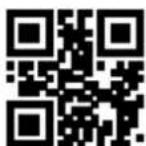
The Baud Rate is in bps: bits per second. You can scan the following programming barcodes to select configuration parameters.
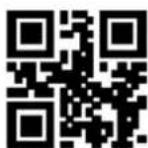
1200bps
4800bps
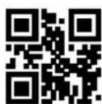
**9600bps
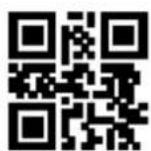
14400bps
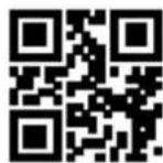
19200bps

38400bps
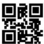
57600bps
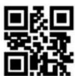
115200bps
2.2.2 Parity Methods
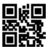
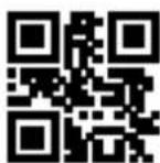
There are 3 alternative parity methods, as follows:

**None
2.3 Configuration of USB-HID Interface Related Parameter
2.3.1 Selection of HID Devices
When the product is set as HID devices, it could be two different devices. Users can scan the following programming barcode to set.
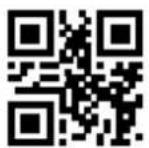
**HID-KBW
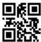
HID-POS
HID-POS acquire scan data
After scanning and decoding a barcode, the device would send the following input message.
| Data reception | ||||||||
| Bit | ||||||||
| Byte | 7 | 6 | 5 | 4 | 3 | 2 | 1 | 0 |
| 0 | Message ID=0x02 | |||||||
| 1 | Bar Code Data Length | |||||||
| 2 | Fixed Value 0x5d | |||||||
| 3 | Fixed Value 0x51 | |||||||
| 4 | Fixed Value 0x31 | |||||||
| 5-60 | Barcode Data | |||||||
| 61 | Barcode Data | |||||||
| 62 | Fixed Value 0x51 | |||||||
| 63 | 0x01 (followed by packets)/0x0 (followed by no packets) | |||||||
2.3.2 Access Cycle of PC to HID Device
You can modify the access period of PC to HID device by reading the following programming barcode. The period ranges from 1ms to 64ms.
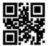
**1ms

3ms

5ms

10ms
2.3.3 Timeout Before HID Release
After reading the following programming barcode, you can modify the timeout before the HID is released (that is, the timeout from valid message to release message). The timeout is from 1ms to 63ms.

**1ms
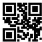
2ms

5ms

10ms
2.3.4 Timeout After HID Release
After reading the following programming barcode, you can modify the timeout after the HID is released (that is, the timeout from the release of the message to the next valid message). The timeout is from 1ms to 63ms.

**lms

2ms

5ms

10ms
2.3.5 CapsLock Status Settings

** CapsLock-Off

CapsLock-On
2.3.6 Leading Key Output
Users can scan the following programming barcode to enable HID to output a preamble message before outputting each piece of data, which is convenient for client as to software development and positioning.
The key value is Ctrl+Shift+r.

** Disable HID Leading Key Output

Enable HID Leading Key Output
3. Scanning Mode
3.1 Manual Mode
Manual mode is a default scanning module. In manual mode, press the trigger button, the scanning module starts shooting and reading. In the limited duration of "Decode Session Timeout". After successful reading, the scanning module will output the scanned content through the communication interface and stop reading, if you need to one more reading, you need to re-trigger the button. If the reading exceeds the length of a single reading in time duration, the shooting and reading will be stopped.

Manual Mode
3.1.1 Trigger Conditions
The trigger condition can be selected in the manual mode. The trigger condition defaults to level triggering and level triggering.
Edge triggering refers to the detection of the level pulse of the trigger signal, that is, start reading, and the reading is ended when the reading is successful or the decode session timeout condition is reached.
The Level Trigger condition refers to the level at which the trigger signal needs to be held during the start of reading to the end of reading. When the trigger level is cancelled, the reading is successful, or the reading is longer than the single reading duration, the reading is ended.

Edge Trigger
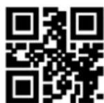
**Level Trigger
3.1.2 Decode Session Timeout
Decode Session Timeout is the time allowed to conduct the longest reading after the reading is triggered. When the time is exceeded, it will exit the reading state. The range is from 100ms to 25500ms. Scan the following programming barcode to set the Decode Session Timeout.
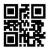
1000ms

3000ms

**5000ms
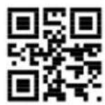
10000ms

Infinite
3.2 Command Trigger Mode
In the command trigger mode, the scanning module starts shooting and reading after receiving the trigger signal command sent by the host (that is, the bit 0 of the flag bit 0x0002 is written to "1"); within the limited time range of "decode session timeout" If the reading is successful, the scanning module will output the scan content through the communication interface and stop reading. If a new reading is to be booted, the trigger command needs to be resent. If the reading exceeds the length of a single reading in time duration, the reading will be stopped.

Command Trigger Mode
Note: In the command trigger mode, the serial command of the trigger signal is: 7E 00 08 01 00 02 01 AB CD; After receiving the scan commands, the serial port returns the write success command: 02 00 00 01 00 33 31, the scanning module is booted.
Trigger command answer switch
Read the following setting codes to allow and prohibit the trigger command response.

Trigger command response disable
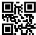
** Trigger command response allowed
3.2.1 Decode Session Timeout
For the single reading duration setting, please refer to 3.1.2 Decode Session Timeout Code to set.
3.3 Continuous Mode
Continuous Mode is a way for the scanning module to continuously capture, scan and output information.
In this mode, it is defaulted to go into the 1000ms reading timeout after successful reading.
In Continuous Mode, you can use the trigger level control to pause continuous reading or continue reading continuously. In continuous reading, it is necessary to maintain the trigger level of 50ms or more and then cancel it, so that the reading will be suspended. When the reading state is suspended, the trigger level of 50ms or more is also maintained and then canceled, and the reading is continued.

Continuous Mode
3.3.1 Timeout Between Decodes
It refers to the timeout between the next reading and the current successful reading. No acquisition is performed during this timeout. Scan the following programming barcode to set timeout between decodes. The setting is from 0ms to 25500ms, and the default duration is 1000ms.
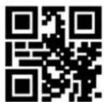
No Timeout
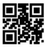
500ms

**1000ms
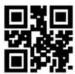
3000ms

5000ms
3.3.2 Timeout between Decodes (Same Barcode)
In order to avoid the same barcode being continuously scanned for multiple times in continuous mode, Timeout between Decodes (Same Barcode) is required for scanning module in this mode before enabling the same barcode. Timeout between Decodes (Same Barcode) means that the same barcode will not be read if it has been scanned within the set timeout. It can only be read and output beyond the timeout. By default, Timeout between Decodes (Same Barcode) is turned off.
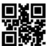
ON

**OFF
Scan the following programming barcode to set Timeout between Decodes (Same Barcode). Setting range: 0ms\~12700ms.
Note: The delay time setting can be set only after the "Timeout between Decodes (Same Barcode)" is turned on.
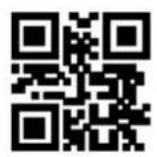
Infinite Delay

500ms
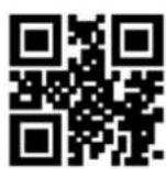
1000ms

3000ms
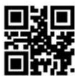
5000ms
3.3.3 Decode Session Timeout
For the decode session timeout, please refer to the programming barcode of Section 3.1.2 Decode Session Timeout.
3.3.4 Continuous mode key pause switch
When "Continuous Mode Key Pause Support" is set, the continuous mode trigger can be suspended by pressing the key for the first time, and the continuous mode trigger can be started by pressing the key again; When "Continuous mode key pause is not supported" is set, the key is invalid for continuous mode.
The user can set the continuous mode key pause switch through the following setting code.

** Continuous mode key pause supports

Continuous mode key pause is not
3.4 Sense Mode
Sense Mode refers to a working mode in which the scanning module conducts reading by sensing the change in brightness of the surrounding environment. When the scene changes, the scanning module begins to scan. After successful reading and outputing information or the Decode Session Timeout, the scanning module needs to be separated for a certain period(can be set) to re-enter the monitoring state. If the following
conditions do not occur, the scanning module will cycle in the above manner: the barcode is not scanned within a Decode Session Timeout, and the scanning module will automatically pause the reading and enter the monitoring state. In the sensing scanning module, the scanning module can also boot reading by pressing the trigger button, and continue to monitor the brightness of the surrounding environment after the reading succeeds in outputting the information or releasing the trigger button.

Sense Mode
3.4.1 Decode Session Timeout
For the setting of decode session timeout, please refer to the programming barcode in Section 3.1.2 Decode Session Timeout to set.
3.4.2 Timeout between Decodes
For the setting of the timeout between decodes, please refer to the programming barcode in Section
3.2.1 Timeout between Decodes to set.
3.4.3 Timeout between Decodes (Same Barcode)
For setting Timeout between Decodes (Same Barcode), please refer to the programming barcode in
3.4.4 Sensitivity
Sensitivity refers to the degree of changes in the scene detected in the inductive scanning module.
When the scanning module meets the requirements in telling the degree of scene changes, it will switch from the monitoring state to the reading state.
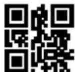
Low Sensitivity

**Medium Sensitivity

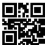
3.4.5 Image Stabilization Timeout
Image Stabilization Timeout refers to the period for which the scanning module that detects the scene change needs to wait for the image to stabilize before reading the code in the inductive scanning module. The settling range of image stabilization timeout is 0\~25500 ms, and the step size is 100ms. The default image stabilization timeout is 400ms.

**0ms

100ms

400ms

1000ms

2000ms
4. Filling Light
4.1 Fill Light
There is a set of LEDs on the scanning module that are specially equipped for shooting, providing auxiliary fill light, illuminating the light beams on the reading targets, improving the adaptability of recognizing performance and weak ambient light. You can set it according to the actual use:
Fill Light - ON when Photographing: The fill light lights up while shooting and goes out if there is no shooting.
Fill Light - always ON: The fill light continues to glow after the scanning module is turned on.
Fill Light - always OFF : the fill light does not light up in any cases.

**Fill Light - ON when Photographing

Fill Light - always ON

Fill Light - always OFF
4.2 Positioning
The scanning module has an auxiliary device for positioning, which projects a pointing line during shooting to remind users of reading the center of the scene image captured by the module.
Positioning Light - ON when Photographing : the positioning light is lit up during shooting and goes out when there is no shooting.
Positioning light -always ON when Photographing : the positioning light is always on when taking pictures and goes out at other times.
^F Positioning Light - always ON: the positioning light continues to illuminate after the scanning module is turned on.
Positioning Light - always OFF : the positioning light does not illuminate in any cases.

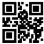
**Positioning Light - ON when Photographing Positioning light -always ON when Photographing

Positioning Light - always ON

Positioning Light - always OFF
5. Prompt Output
5.1 Buzzer Master Switch
Scan the following programming barcode to turn on /off all of the beep sounds.

Mute_ON

**Mute _ OFF
5.2 Buzzer Settings
5.2.1 Passive Buzzer
Scan the following programming barcode to set the buzzer to passive and set the drive frequency of the passive buzzer.

**Passive Buzzer

Passive_Low Frequency

**Passive_Intermediate Frequency

Passive_High Frequency
5.2.2 Active Buzze
Scan the following programming barcodes to set the buzzer as active one and set the active buzzer's operating level. Scan "High Level", the buzzer is set to active low when idle, and active high level when working; scan "Low Level", the buzzer is set to active high when idle, and active low level when working.
Active Buzzer

**High Level
Low Level
5.3 Good Read Beep for Programming Barcode
Scan the following programming barcodes to enable/disable the programming barcode beep

** Beep for Programming Barcode_ON

Beep for Programming Barcode_OFF
5.4 Startup Beep
When the scanning module is on after power on, the scanning module can output or turn off the startup beep according to the setting requirements.
** Startup Beep_ON
Startup Bccp_OFF
5.5 Good Read LED/Beep
After the scanning module is successfully scan the codes, BEEP and DLED prompt signals are output through the 12pin external interface by default, and the external passive buzzer and LED are used for prompting. These signals can be turned off if the user requires to do so.

** Good Read LED_ON

Good Read LED_OFF

**Good Read Beep_ON

Good Read Beep_OFF
The user can set the timeout of Good Read Beep, by reading the following programming barcodes.

30ms

**60ms

90ms

120ms
5.6 Data Output Encoding Format
Users can set the output format of the scanning module through the following programming barcodes,
so that the host can output Chinese data according to the specified encoding format.
Note:
GBK format is used for Text., UNICODE format is used for Word and input box of common chat tool.
The Original Data output is used to encrypt the serial output of the data.
**GBK

UTF8

Original Data

UNICODE
5.7 Different Country Keyboard Settings
In order to apply it in different countries, the device can be set as the corresponding "keyboard" of each country by the following programming barcodes.

**US

Czech


French
Germany

Hungary

Italy

Japan

Spain
Turkey Q
Turkey F

Mexico (Latin America)
5.8 Virtual keyboard enable
In order to apply it in more regional application environments, the standard/virtual keyboard output settings can be made by reading the following programming barcodes. But that will cause a certain loss in output efficiency. Note that when using a virtual keyboard, you must ensure that the keypad number keys are enabled.

**Standard Keyboard
Virtual Keyboard
1. Virtual keyboard output mode
In order to adapt to different application scenarios, the virtual keyboard has two different output modes for control characters less than 0x20, and users can switch by scanning the following setting codes.

** Control character output off

Ctrl Mode

Alt Mode
**Control Character Output Off
2. Control character transmission
ASCII characters between 0x00 and 0x1F can be escaped as a control function key. When the virtual keyboard is enabled (other HID Keyboard of the module is set as default value), the input operation of the control function key is as follows: (Please refer to the control character correspondence table for the corresponding relationship between the specific ASCII value and the control function key)
(1) Virtual keyboard Ctrl Mode on
Read the characters whose data is "A < HT > F (HT is an invisible character and is not displayed on the terminal software)" (hexadecimal values are 0x41/0x09/0x46 respectively), and the virtual keyboard operation of the scanning module is as follows:
Enter "A"-press key A;
Enter "Ctrl I"-since the data of 0x09 corresponds to the control function key "I", the virtual keyboard would hold down Ctrl, then press the I key, and finally release the Ctrl key and the I key at the same time;
Enter "F"-press key F.
Since "Ctrl I" corresponds to the function of converting characters into italics in some word processing software, completing the above operation may result in normal characters "A" and italic "F".
At present, in QL1601 small module, the virtual keyboard Ctrl mode "control character output only supports American keyboard layout.
(2) Virtual keyboard Alt mode
If the virtual keyboard is turned on and set to "ALT Mode", the output corresponding control character operation is: ALT + "Character corresponds to ASCII decimal value". For example, for "
Enter "Alt 0 9"-the virtual keyboard would hold down Alt, then press "0" and "9" of the numeric keypad, and finally release Alt.
When the standard keyboard outputs, the control character output function is turned off, and ASCII characters less than 0x20 would output the corresponding key value function. (For corresponding functions, please refer to the Control Character Correspondence Table)
Control character correspondence table
| ASCII Function | ASCII Value(HEX) | Control Character Output Off | Ctrl Mode | CTRL+X Funciton |
| NUL | 0 | Null | Ctrl+@ | |
| SOH | 1 | KeypadEnter | Ctrl+A | Select all |
| STX | 2 | CapsLock | Ctrl+B | Bold |
| ETX | 3 | ALT | Ctrl+C | Copy |
| EOT | 4 | Null | Ctrl+D | Bookmark |
| ENQ | 5 | CTRL | Ctrl+E | Center |
| ACK | 6 | Null | Ctrl+F | Find |
| BEL | 7 | Enter | Ctrl+G | |
| BS | 8 | LeftArrow | Ctrl+H | History |
| HT | 9 | Horizontal Tab | Ctrl+I | Italic |
| LF | 0A | DownArrow | Ctrl+J | Justify |
| VT | 0B | Vertical Tab | Ctrl+K | hyperlink |
| FF | 0C | Delete | Ctrl+L | list,left align |
| CR | 0D | Enter | Ctrl+M | |
| SO | 0E | Insert | Ctrl+N | New |
| SI | 0F | Esc | Ctrl+O | Open |
| DLE | 10 | F11 | Ctrl+P | |
| DC1 | 11 | Home | Ctrl+Q | Quit |
| DC2 | 12 | PrintScreen | Ctrl+R | |
| DC3 | 13 | Backspace | Ctrl+S | Save |
| DC4 | 14 | tab+shift | Ctrl+T | |
| NAK | 15 | F12 | Ctrl+U | |
| SYN | 16 | F1 | Ctrl+V | Paste |
| ETB | 17 | F2 | Ctrl+W | |
| CAN | 18 | F3 | Ctrl+X | |
| EM | 19 | F4 | Ctrl+Y | |
| SUB | 1A | F5 | Ctrl+Z | |
| ESC | 1B | F6 | Ctrl+[ | |
| FS | 1C | F7 | Ctrl+\ | |
| GS | 1D | F8 | Ctrl+] | |
| RS | 1E | F9 | Ctrl+6 | |
| US | 1F | F10 | Ctrl+- |
5.9 Chinese output shielding
Enable this function, the device shields Chinese output. The user can read the following setting code to open and close the Chinese output shielding function.

**Chinese output shielding-OFF

Chinese output shielding-ON
5.10 Analog keypad
5.10.1 Output of numeric function of keypad
If this function is not turned on, all outputs would be output according to the corresponding key value of the large keyboard.
After this function is turned on, only the numbers "0\~9" in the decoded data obtained by the reading module are output according to the key values corresponding to the small keyboard, and the rest are output according to the key values corresponding to the large keyboard.
The user can turn on and off the digital output function of the analog keypad by reading the following setting codes.
Keypad Numeric Output-On
**Keypad Numeric Output-Off
5.10.2 Output of keypad operator function
If this function is not turned on, all outputs would be output according to the corresponding key value of the large keyboard.
After this function is turned on, only "+"_""*/" in the decoded data obtained by the reading module is output according to the key value corresponding to the small keyboard, and the rest is output according to the key value corresponding to the large keyboard.
The user can turn on and off the output function of analog keypad operators by reading the following setting codes.

Keypad Operator Output-On

**Keypad Operator Output-Off
5.11 Image Mirroring Mode
When there is mirror flip in image, you can boot the mirror flip mode by reading the following programming barcodes.
Image Mirror Flip_ON

** Image Mirror Flip_OFF
Note: In the mirror flip mode, only the barcode of the mirror flip can be recognized. Please exit the mirror flip mode first before identifying the normal barcode or programming barcode.
5.12 Reverse Scanning Module
In some special application scenarios, special barcodes for black and white inversion need to be enabled. The user can enable/disable the reading function of inverse video code by reading the following programming barcodes.

**Video Reverse OFF
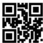
Video Reverse ON
5.13 Invoicing mode
In order to facilitate the use of this module in the billing system, users can configure the billing mode by reading the setting code, and realize the format conversion and output of the invoice code. Invoicing modes include local invoicing mode and online invoicing mode. When invoicing mode is enabled, local invoicing mode is used by default.
Users can realize the format conversion and output of invoice codes by reading the following setting codes.

** Invoicing Mode Enable

Invoicing Mode Disable
After the invoice mode is opened, you can select the invoicing mode by reading the following setting codes.

** Local Invoicing Mode

Online Invoicing Mode
It should be noted that when the user uses the online billing mode, the module must be switched to the HID-POS output mode only and used in combination with the WSM billing assistant.
5.14 Read Device Version Information
Users can quickly obtain the current device version information and all the device version information by reading the following setting codes.

Read device version information

Read all device version information
5.15 Write/Read Device ID
Users can read and write ID through serial port or virtual serial port.
The ID information include:
SN: product serial number
FID: Manufacturer Information
MID: Product Model
ID up to 64 bytes (pure numbers and upper and lower case letters)
Write ID format:
WriteDeviceID:SN:xxxx;MID:xxxx;FID:xxxx. (Can be changed according to requirements)
The return value of the write ID instruction is: The same as that of the write ID instruction
Read ID format:
ReadDeviceID.
Return: SN:xxxx;MID:xxxx;FID:xxxx.
For example: write device ID information for device: SN: 20200508; MID: WSM1605; FID: WSM
2020., and read that device ID by command
Write ID:
Serial port sending: WriteDeviceID:SN:20200508;MID:WSM1605;FID:WSM2020.
WriteDeviceID:SN:20200508;MID:WSM1605;FID:WSM2020.
Serial port return: WriteDeviceID:SN:20200508;MID:WSM1605;FID:WSM2020.
Read ID:
Serial port sending: ReadDeviceID.
Serial port return: SN:20200508; MID:WSM1605; FID:WSM2020.
Note:
- The instruction is followed by "." as the closing mark.
- When SN, FID, MID are not written, read the DeviceID of the device and return "SN:NULL;MID: NULL;FID: NULL."
- If the write instruction ID data does not meet the requirements or the instruction format is wrong, send a write instruction to return "FALSE" or not, and the write fails.
The user can also read DeviceID by reading the following setting codes, and the return format is consistent with the reading of the sending instruction.

Read Device ID
5.16 Read Chip SN
Users can quickly obtain SN information of the current device chip by reading the following setting codes.

Read chip SN number
6. Prefix & Suffix
In practical applications, in order to facilitate data differentiation processing, sometimes it is necessary for the read data to be edited before being output.
Prefix & Suffix include:
Prefix
◆ Suffix
◆ Decode data segment interception
◆ Code ID
◆ Tails
◆ Decoding failure feature output information (RF Information)
Processed output data format:
【Prefix】【Code ID】【Data】【Suffix】【Tail】
6.1 Prefix
Prefix is a string of strings defined by the user before the data is decoded. The user can add and modify the prefixes by reading the following programming barcodes.

Enable Prefixes
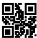
**Disable Prefixes
Scan the following programming barcode, with the programming barcode of "Digit Barcodes
" and the programming barcode of "save", the user can modify the prefixes.

Modify Prefix
Note: A prefix has 15 characters at most and two hexadecimal values is for a prefix character. Refer to
Appendix F for the hexadecimal conversion table of character values.
6.2 Suffix
Suffix is a string of strings defined by the user before the data is decoded. The user can add and modify the prefixes by reading the following programming barcodes.

Enable Sufixes

**Disable Sufixes
Scan the following programming barcode, with the programming barcode of "Digit Barcodes" and the programming barcode of "save", the user can modify the suffixes.

Modify Suffix
Note: A suffix has 15 characters at most and two hexadecimal values is for a prefix character. Refer to Appendix F for the hexadecimal conversion table of character values.
6.3 Code ID
6.3.1 Custom Code ID
Code ID uses one character. Users can customize Code ID by reading the following programming barcodes to identify different barcode types.

Enable Code ID
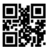
** Disable Code ID
Scan the following programming barcode to restore the default value of Code ID of the barcode. The default list can be found in Appendix E.

Restore Default Code ID
6.3.2 Modify Code ID
Users can modify the Code ID corresponding to each barcode by reading the following programming barcodes.

Modify EAN13 Code ID
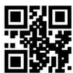
Modify EAN8 Code ID

Modify UPC-A Code ID

Modify UPC-E0 Code ID
This function is used in scenarios where the user needs to output partial decoded information.
The decoding information Data consists of three parts:
【Start】【Center】【End】
The user can select some of the information that needs to be output by reading the following programming barcodes.

** Transmit all Data
Tansmit the Start Data

Tansmit the END Data

Tansmit the Center Data
6.5.2 Modify the Length for Data
The user can modify the length of the Start Data and the length of the End Data by reading the following programming barcodes, combined with the programming barcodes of "Digit Barcodes" and "Save". Both the Start and End segments have up to 255 characters, and both are represented by a hexadecimal character for their length. The characters which are corresponding to the hexadecimal conversion table can be found in Appendix F.

Modify the Length for Start Data

Modify the Length for End Data
6.6 RF Information
The Scan Fail (RF) information is the output information after the scanning module fails to scan the codes, so that the user or the program can adjust or operate after detecting the information. Users are free to define RF information.
Scan the following programming barcode to enable/disable RF transmitting.
Enable Transmitting RF Information

** Disable Transmitting RF Information
Scan the following programming barcode, combined with the programming barcode of "Digit Barcodes" and "save", you can modify the RF information by yourself, and two hexadecimal values is for a prefix character, there are 15 characters at most. Refer to Appendix F for the character-to-hexadecimal conversion table.
Modify RF Information
Note: When an odd number of hexadecimal values are input, if it is failed to set the last bit, only the first few characters are output.
6.7 Output Protocol
The user can decode the output format of result by reading the following programming barcodes to modify the virtual serial port/serial port mode.
The format of the decoding result with the protocol output is: <03>
Note: The protocol mode must adopt UTF-8 encoding output format. In other output encoding formats, only raw data can be output regardless of whether the output with protocol is selected.

**Raw Data

With Protocol
6.8 GS Character Replacement
GS, as a group separator, was applied to the bar code of the European Food and Drug Administration after the 2012 London Olympics. Because GS characters are invisible in many text display tools, some areas need to replace GS with displayable character output. That is, replace the 0x1D byte in the ASCII code table with the displayable byte in ASCII.
At present, the QR decoding module temporarily supports replacing GS with characters in 0x20-0x7E in ASCII.
The alternative method is as follows:
1) Read the setting code of "GS character replacement enable";
2) Read the setting code of "GS replacement character modification";
4) Read the "Save" setting code.
3) The characters replaced by GS are represented by two hexadecimal values, and the characters correspond to the hexadecimal conversion table refer to Appendix F

GS Character Replacement Enable

**GS Character Replacement Disable
Read the following setting codes, cooperate with the "data code" setting code and the "save" setting code, and the user can modify GS replacement characters.

GS Alternate Character Modification
6.9 Web address code recognition
Read the following setting codes, and you can set the permission and prohibition of the website code reading function

** Enable Reading Of Web Address Codes

Disable rReading Of Web Address Codes
7. Quick Operation
7.1 Fast POS Mode
POS Mode features:
◆ Scan mode: Command Trigger Mode
◆ Communication port: Serial Port
◆ Startup Beep OFF
◆ Tail OFF
Users can quickly configure the reading device to work in POS Mode by reading the following programming barcode.

Fast POS Mode
7.2 Serial Port & Full Codes On Mode
In order to facilitate the quick configuration and switch to the serial port and full codes open mode during the secondary development process, you can realize the quick configuration function by reading the following programming barcodes.

Serial Port & Full Codes ON
8. Symbologies
8.1 Global Shortcuts
8.1.1 Global Operations
The user can globally enable/Disable and enable the default reading type for all supported code systems by reading the following programming barcodes. After reading all types of code systems, only the programming barcode is enabled.

Enable All Symbologies

Disable All Symbologies

** Enable Default Symbologies
8.1.2 Product Barcode Check Digit Output Enable
The user can enable/disable the commodity barcode check digit output by reading the following programming barcode (commodity barcode includes: EAN13/EAN8/UPC-A/UPC-E0/UPC-E1).

**Enable Transmit Check Digit

Disable Transmit Check Digit
8.1.3 Enhancement of literacy
Enabling and disabling bar code reading ability enhancement can be carried out by reading the following setting codes. After the ability to read is strengthened and enabled, the ability to read special codes such as defaced bar codes and QR code surfaces can be improved. The strengthening of reading ability and prohibition would improve the decoding speed.
** Enhancement of literacy prohibits

Enhancement of literacy enable
8.2 1D Symbologies
8.2.1 EAN 13
1. Enable or Disable EAN13
The user can enable and disable the EAN13 barcode reading function by reading the following programming barcodes.
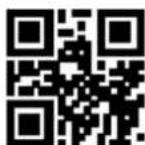
**Enable EAN13

Disable EAN13
2. Enable or Disable Add-On Code
The user can enable and disable the forced output function of EAN13 add-on code by reading the following programming barcodes.
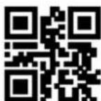
EAN13 Add-On Code Required

** EAN13 Add-On Code Not Required
The user can enable and disable the configuration of the EAN13 add-on code by reading the following programming barcodes.

Enable EAN13-2 Digit Add-On Code

Enable EAN13-5 Digit Add-On Code

** Disable EAN13-2 Digit Add-On Code
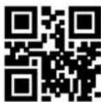
** Disable EAN13-5 Digit Add-On Code
3. Check bit Output Function Enable and Disable

** Enable Transmission of EAN13 Parity Bits

Disable Transmission of EAN13 Parity Bits
8.2.2 EAN 8
1. Enable or Disable EAN8
The user can enable and disable the EAN8 barcode reading function by reading the following programming barcodes.

**Enable EAN8
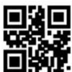
Disable EAN8
2. Enable or Disable Add-On Code
The user can enable and disable the forced output function of EAN8 add-on code by reading the following programming barcodes.
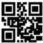
EAN8 Add-On Code Required

** EAN8 Add-On Code Not Required
The user can enable and disable the configuration of the EAN8 add-on code by reading the following programming barcodes.

Enable EAN8-2 Digit Add-On Code
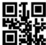
** Disable EAN8-2 Digit Add-On Code
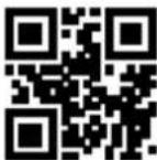
Enable EAN8-5 Digit Add-On Code

** Disable EAN8-5 Digit Add-On Code
3. Check bit Output Function Enable and Disable
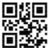
** Enable Transmission of EAN8 Parity Bits

Disable Transmission of EAN8 Parity Bits
8.2.3 UPC-A
4.1. Enable or Disable UPC-A
The user can scan and disable the UPC-A barcode reading function by reading the following programming barcodes.

**Enable UPC-A

Disable UPC-A
2. Enable or Disable Add-On Code
The user can enable and disable the forced output function of UPC-A add-on code by reading the following programming barcodes.

UPC-A Add-On Code Required

** UPC-A Add-On Code Not Required
The user can enable and disable the configuration of the UPC-A add-on code by reading the following programming barcodes.

Enable UPC-A-2 Digit Add-On Code

** Disable UPC-A-2 Digit Add-On Code

Enable UPC-A-5 Digit Add-On Code
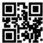
** Disable UPC-A-5 Digit Add-On Code
3. Enable Conversion from UPC-A to EAN13
The user can enable/disable the conversion of UPC-A to EAN13 by reading the following programming barcodes.

Enable UPC-A to EAN13

** Disable UPC-A to EAN13
5. Check bit Output Function Enable and Disable


8.2.4 UPC-E0
1. Enable or Disable UPC-E0
The user can scan and disable the UPC-E0 barcode reading function by reading the following programming barcodes.

**Enable UPC-E0

Disable UPC-E0
2. Enable or Disable Add-On Code
The user can enable and disable the forced output function of UPC-E0 add-on code by reading the following programming barcodes.

UPC-E0 Add-On Code Required

** UPC-E0 Add-On Code Not Required
The user can enable and disable the configuration of the UPC-E0 add-on code by reading the following programming barcodes.

Enable UPC-E0-2 Digit Add-On Code
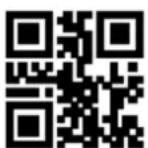
** Disable UPC-E0-2 Digit Add-On Code

Enable UPC-E0-5 Digit Add-On Code
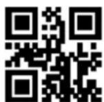
** Disable UPC-E0-5 Digit Add-On Code
3. Check bit Output Function Enable and Disable

** Enable Transmission of UPC-E0 Parity Bits

Disable Transmission of UPC-E0 Parity Bits
8.2.5 UPC-E1
The user can enable and disable the UPC-E1 barcode reading function by reading the following programming barcodes.

**Enable UPC-E1
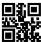
Disable UPC-E1
2. Enable or Disable Add-On Code
The user can enable and disable the forced output function of UPC-E1 add-on code by reading the following programming barcodes.
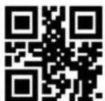
UPC-E1 Add-On Code Required
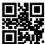
** UPC-E1 Add-On Code Not Required
The user can enable and disable the configuration of the UPC-E1 add-on code by reading the following programming barcodes.

Enable UPC-E1-2 Digit Add-On Code

** Disable UPC-E1-2 Digit Add-On Code

Enable UPC-E1-5 Digit Add-On Code
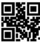
** Disable UPC-E1-5 Digit Add-On Code
3. Check bit Output Function Enable and Disable

** Enable Transmission of UPC-E1 Parity Bits

Disable Transmission of UPC-E1 Parity Bits
8.2.6 Code128
1. Enable or Disable Code128
The user can enable and disable the Code128 barcode reading function by reading the following programming barcodes.

**Enable Code128
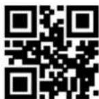
Disable Code128
2. Set Length Range for Code128
Users can set the minimum and maximum length of Code128 by reading the following programming barcodes.
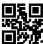
**Set the Minimum Length for Code128 to 0
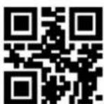
Set the Minimum Length for Code128 to 4

Set the Maximum Length for Code128 to 32
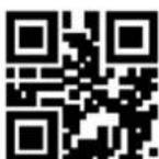
**Set the Maximum Length for Code128 to 255
3. Code 128 prefixed (11)
The user can turn on or off the Code128 barcode prefix (11) function by reading the following setting codes.

Code128 Prefix (11)-On
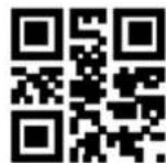
**Code128 Prefix (11)-Off
8.2.7 Code39
1. Enable or Disable Code39
The user can enable and disable the Code39 barcode reading function by reading the following programming barcodes.

**Enable Code39
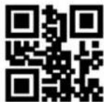
Disable Code39
2. Set Length Range for Code39
Users can set the minimum and maximum length of Code39 by reading the following programming barcodes
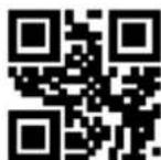
**Set the Minimum Length for Code39 to 0
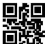
Set the Minimum Length for Code39 to 4
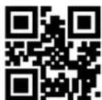
Set the Maximum Length for Code39 to 32

**Set the Maximum Length for Code39 to 255
3. Transmit Start/Stop Character
The user can set the output of Code39 Start/Stop Character by reading the following programming barcodes.

Output of Code39 Start Character
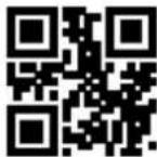
**Disable Output of Code39 Stop Character
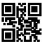
Output of Code39 Stop Character

**Disable Output of Code39 Stop Character
4. Code32 Mode
Users can choose whether Code39 supports Code32 mode by reading the following programming barcodes.

Support Code32 Mode
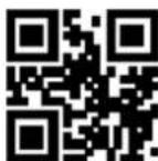
** Disable Support Code32 Mode
Users can choose whether Code 32 outputs the prefix A by reading the following programming barcodes.

**the output of Code 32 prefix A
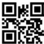
Disable output of Code 32 prefix A
5. FullAsc Mode
Users can choose whether Code39 supports FullAsc mode by reading the following programming barcodes.
Support FullAsc Mode

**Disable Support FullAsc Mode
6. Proces Verification
The user can set whether Code39 handles verification by reading the following setting code.
Code 39 Handles Verification

**Code 39 Does Not Handle Verification
8. Parity bit Output
The user can set whether Code39 outputs check bits by reading the following setting codes.

Code39 Outputs Parity Bits

**Code39 Does Not Output Parity Bits
8.2.8 Code93
1. Enable or Disable Code93
The user can enable and disable the Code93 barcode reading function by reading the following programming barcodes.

**Enable Code93

Disable Code93
2. Set Length Range for Code93
Users can set the minimum and maximum length of Code93 by reading the following programming barcodes.
**Set the Minimum Length for Code93 to 0
Set the Minimum Length for Code93 to 4

Set the Maximum Length for Code93 to 32
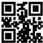
**Set the Maximum Length for Code93 to 255
8.2.9 CodaBar
1. Enable or Disable CodaBar
The user can enable and disable the CodaBar barcode reading function by reading the following programming barcodes.

**Enable CodaBar

Disable CodaBar
2. Set Length Range for CodaBar
Users can set the minimum and maximum length of CodaBar by reading the following programming barcodes.
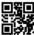
**Set the Minimum Length for CodaBar to 0

Set the Minimum Length for CodaBar to 4

Set the Maximum Length for CodaBar to 32
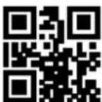
**Set the Maximum Length for CodaBar to 255
3. Transmit Start/Stop Character
The user can set the output of CodaBar Start/Stop Character by reading the following programming barcodes.
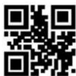

4. Verification Processing
The user can set CodaBar check processing by reading the following setting codes.

** CodaBar Do Not Process Verification
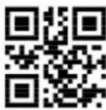
CodaBar Mod10 Check
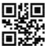
CodaBar Mod16 Check
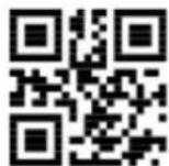
CodaBar Double Check
5. Parity Bit Output Setting
The user can set the output of CodaBar check bits by reading the following setting codes.
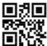
CodaBar Parity Bit Output

**CodaBar Parity Bit Not Output
8.2.10 Interleaved 2 of 5
1. Enable or Disable Interleaved 2 of 5
The user can enable and disable the Interleaved 2 of 5 barcode reading function by reading the following programming barcodes.
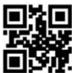
Enable Interleaved 2 of 5
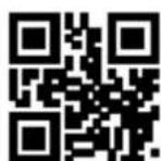
**Disable Interleaved 2 of 5
2. Set Length Range for Interleaved 2 of 5
Users can set the minimum and maximum length of Interleaved 2 of 5 by reading the following
programming barcodes.

Set the Minimum Length to 0

**Set the Minimum Length to 4

**Set the Maximum Length to 32
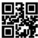
Set the Maximum Length to 255
3. Verify Format Setting
The user can set whether Interleaved 2 of 5 processes verification by reading the following setting code.

Interleaved 2 of 5 Verification Format Mod10

**Interleaved 2 of 5 Verification Format NONE
4. Parity Bit Output Setting
The user can set whether Interleaved 2 of 5 outputs check bits by reading the following setting code.

Interleaved 2 of 5 Outputs Parity Bits

**Interleaved 2 of 5 Does Not Output Parity Bits
8.2.11 Industrial 25
1. Enable or Disable Industrial 25
The user can enable and disable the Industrial 25 barcode reading function by reading the following programming barcodes.

Enable Industrial 25
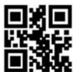
**Disable Industrial 25
2. Set Length Range for Industrial 25
Users can set the minimum and maximum length of Industrial 25 by reading the following programming barcodes

Set the Minimum Length to 0

**Set the Minimum Length to 4
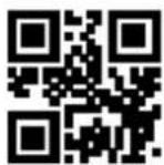
**Set the Maximum Length to 32

Set the Maximum Length to 255
3. Verify Format Setting
The user can set whether Industrial 25 processes verification by reading the following setting code.
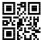
Industrial 25 Verification Format Mod10
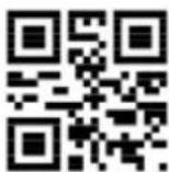
**Industrial 25 Verification Format NONE
4. Parity Bit Output Setting
The user can set whether Industrial 25 outputs check bits by reading the following setting code.
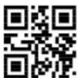
Industrial 25 Outputs Parity Bits

**Industrial 25 Does Not Output Parity Bits
8.2.12 Matrix 2 of 5
1. Enable or Disable Matrix 2 of 5
The user can enable and disable the Matrix 2 of 5 barcode reading function by reading the following programming barcodes.

Enable Matrix 2 of 5

** Disable Matrix 2 of 5
2. Set Length Range for Matrix 2 of 5
Users can set the minimum and maximum length of Matrix 2 of 5 by reading the following programming barcodes.

Set the Minimum Length to 0

**Set the Minimum Length to 4

**Set the Maximum Length to 32

Set the Maximum Length to 255
3. Verify Format Setting
The user can set whether Matrix 2 of 5 processes verification by reading the following setting code.
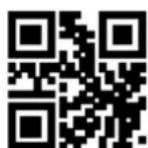
Matrix 2 of 5 Verification Format Mod10

** Matrix 2 of 5 Verification Format NONE
4. Parity Bit Output Setting
The user can set whether Matrix 2 of 5 outputs check bits by reading the following setting code.

Matrix 2 of 5 Outputs Parity Bits

**Matrix 2 of 5 Does Not Output Parity Bits
8.2.13 Code11
1. Enable or Disable Code11
The user can enable and disable the Code11 barcode reading function by reading the following programming barcodes.

Enable Code11

**Disable Code11
2. Set Length Range for Code11
Users can set the minimum and maximum length of Code11 by reading the following programming barcodes.
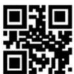
Set the Minimum Length for Code11 to 0

**Set the Minimum Length for Code11 to 4
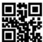
**Set the Maximum Length for Code11 to 32

Set the Maximum Length for Code11 to 255
3. Setting of Check Format
The user can set the check format of Code11 by reading the following programming barcode.
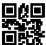

4. Parity Bit Output Setting
The user can set whether Code11 outputs check bits by reading the following setting code.

Code11 Outputs Parity Bits
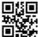
** Code11 Does Not Output Parity Bits
8.2.14 MSI Plessey
- Enable or Disable MSI Plessey
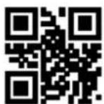
Enable MSI Plessey
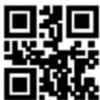
**Disable MSI Plessey
- Set Length Range for MSI Plessey
Users can set the minimum and maximum length of MSI Plessey by reading the following programming barcodes.
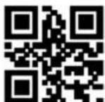
Set the Minimum Length for MSI Plessey to 0
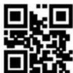
**Set the Minimum Length for MSI Plessey to 4
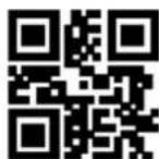
**Set the Max Length for MSI Plessey to 32
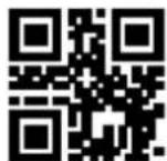
Set the Max Length for MSI Plessey to 255
3. Verify Format Setting
The user can set whether MSI Plessey processes verification by reading the following setting code.
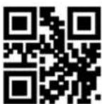
Single Mod10
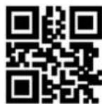
** Double Mod10
4. Parity Bit Output Setting
The user can set whether MSI Plessey outputs check bits by reading the following setting code.

MSI Plessey Outputs Parity Bits

** MSI Plessey Does Not Output Parity Bits
8.2.15 RSS-14
1. Enable or Disable RSS-14
The user can enable and disable the RSS-14 barcode reading function by reading the following programming barcodes.
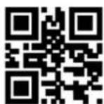
Enable RSS-14

**Disable RSS-14
2. AI () output enable and disable
The user can set whether RSS-14 barcode AI () is output by reading the following setting codes.

**RSS-14 AI Output with Parentheses

RSS-14 AI Output Without Parentheses
8.2.16 RSS-Limited
1. Enable or Disable RSS-Limited
The user can enable and disable the RSS-Limited barcode reading function by reading the following
programming barcodes.

Enable RSS-Limited

**Disable RSS-Limited
2. AI () output enable and disable
The user can set whether RSS-Limited barcode AI () is output by reading the following setting codes.

**RSS-Limited AI Output with Parentheses

RSS-Limited AI Output Without Parentheses
8.2.17 RSS-Expanded
1. Enable or Disable RSS-Expanded
The user can enable and disable the RSS-Expanded barcode reading function by reading the following programming barcodes.
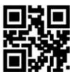
Enable RSS-Expanded
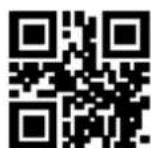
** Disable RSS-Expanded
2. Set Length Range for RSS-Expanded

Set the Minimum Length to 0

**Set the Minimum Length to 4

**Set the Maximum Length to 32
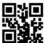
Set the Maximum Length to 255
3. AI () output enable and disable
The user can set whether RSS-Expanded barcode AI () is output by reading the following setting codes.

**RSS-Expanded AI Output with Parentheses

RSS-Expanded AI Output Without Parentheses
8.3 Operation of 2D Symbologies
8.3.1 QR Code
1. Enable or Disable QR Code
The user can enable and disable the QR Code barcode reading function by reading the following programming barcodes.
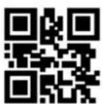
**Enable QR
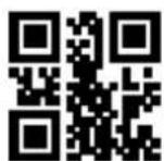
Disable QR
2. Enable or Disable QR Model
The user can enable and disable the QR Model reading function by reading the following programming barcodes.

Enable QR Model
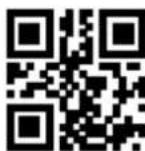
** Disable QR Model
3. QR Code prefixed (11)
The user can turn on or off the c QR barcode prefix (11) function by reading the following setting codes.

QR Prefix (11)-On
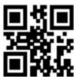
**QR Prefix (11)-Off
8.3.2 Data Matrix (DM)
The user can enable and disable the Data Matrix reading function by reading the following programming barcodes.

**Enable DM
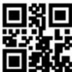
Disable DM
The user can enable and disable simultaneous multiple DM code reading function by reading the following programming barcodes.

Enable Multiple DM
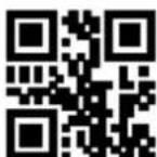
**Disable Multiple DM
8.3.3 PDF417
The user can enable and disable the PDF417 barcode reading function by reading the following programming barcodes.

**Enable PDF417

Disable PDF417
8.3.4 Mico QR
The user can enable and disable the Mico QR barcode reading function by reading the following programming barcodes.

**Enable Mico QR

Disable Mico QR
8.3.5 Chinese Sensible(HanXin) Code
The user can enable and disable the Chinese Sensible(HanXin) Code reading function by reading the following programming barcodes.

Enable Chinese Sensible(HanXin) Code
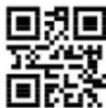
** Disable Chinese Sensible(HanXin) Code
9. Save and Cancel
9.1 Save
After reading the "Digit Barcodes", you need to read the programming barcode of "Save" to save the data.

Save
9.2 Cancel
When an error occurs in the scanned data, the following programming barcode can be scanned to cancel the current setting, also one bit of data which is previous scanned, and a string of data which is previous scanned.

Cancel the Last Digit

Cancel All Digits

Cancel Current Setting
Note: Cancelling the current setting means cancelling all the Digit Barcodes that were scan, and reset shall be conducted after canceling.
10. Batch Setting
When the reading device needs to make multiple setting, setting one by one may be complicated. The user can save all the information to be set into a QR code, and the device can complete multiple setting after reading the QR code.
The following are the guidelines for batch setup:
- Batch processing setting code content format: @ WSM + "Parameter 1"; "Parameter 2"; ..... "Parameter n";
- Please refer to Appendix G Batch Setting Code Content Parameter List for batch setting code content parameters.
- A semicolon (;" is used between every two parameters Separate and end with an English semicolon. Note that there should be no space between the semicolon and the command.
- Batch setting allow up to 30 parameters to be set simultaneously.
- The setting content conforming to the batch processing setting code format is made into QR code in the code making software, and the setting code is read for batch setting.
For example: The programming barcodes of Enter Setup (parameter: 00000000), Sense Mode (parameter: 02000003), Positioning Light - ON when Photographing (parameter: 03000000), Decode Session Timeout-3000ms (parameter: 0202001E) and Disable Interleaved 2 of 5 (parameter: 070A0100). Then the batch processing setting code content is as follows:
@WSM00000000;02000003;03000000;0202001E;070A0100;
When batch setting is required, the setting can be completed by reading the finished batch setting code.
Note:
- When batch setting is carried out, the "setting code is turned on" must be ensured;
If the content of batch setting code does not conform to the setting code rules, or the setting parameters are not included in the list of settable parameters, the setting would fail.
Appendix
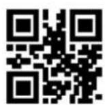
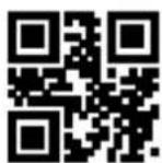
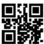
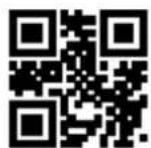
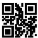
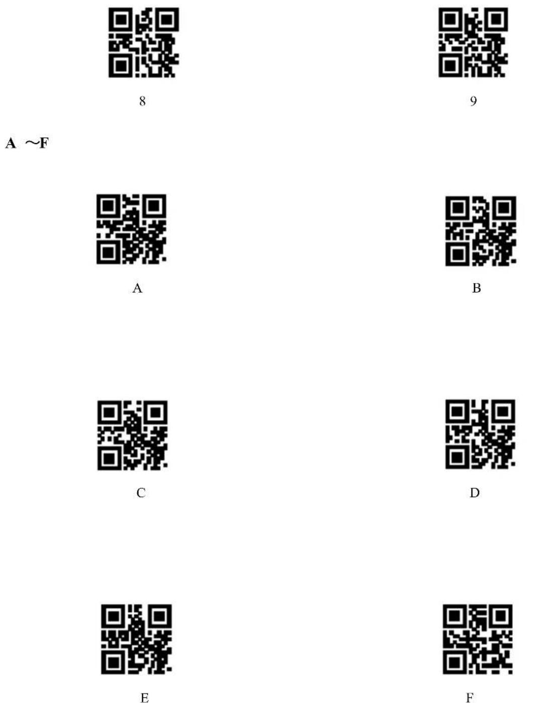
Appendix A: Digit Barcodes
0 \~ 9

0

1
2

3
4
5
6
7
Appendix B: Example of Parameter Settings
◆ Example 1: Modify the prefix to DATA
- Query the character table to obtain the hexadecimal values corresponding to the four characters of "DATA": "44", "41", "54", "41"
- Scan "Enter Setup"; (If it has been enabled, you can skip this step)
- Scan the programming barcode of "Modify Prefix"
- Scan the Digit Barcodess of "4" "4" "4" "1" "5" "4" "4" "1"
- Scan the programming barcode of "Save"
◆ Example 2: Modify the suffix to DATA
- Query the character table to obtain the hexadecimal values corresponding to the four characters of "DATA": "44", "41", "54", "41"
- Read "Enter Setup"; (If it has been enabled, you can skip this step)
- Read the the programming barcode of "Modify Suffix" programming barcode
- Read the Digit Barcodess of "4" "4" "4" "1" "5" "4" "4" "1"
- Read the programming barcode of "Save"
Example 3: Modify EAN13 Code ID to "A"
- Query the character table to obtain the hexadecimal value corresponding to the "A" character: "41"
- Read "Enter Setup"; (If it has been enabled, you can skip this step)
- Read the the programming barcode of "Modify EAN13 Code ID"
- Read the Digit Barcodess of "4" "1" one by one.
- Read the the programming barcode of "Save"
Example 4:
[ Tansmit the Start Data ] If the decoding information is "1234567890ABC", the first 10 bytes "1234567890" shall be output.
- Query the character table to obtain the hexadecimal value corresponding to the "10" character: "0A"
- Read "Enter Setup"; (If it has been enabled, you can skip this step)
- Read the programming barcode of "Modify the Length for Start Data"
-
Read the Digit Barcodess of "0" "A" in turn.
-
Read the programming barcode of "Save"
- Read the programming barcode of "Tansmit the Start Data"
Example 5:
[Tansmit the End Data] If the decoding information is "1234567890ABC", the first 10 bytes "1234567890" shall be output.
- Query the character table to obtain the hexadecimal value corresponding to the "10" character: "0A"
- Read "Enter Setup"; (If it has been enabled, you can skip this step)
- Read the programming barcode of "Modify the Length for End Data"
- Read the Digit Barcodess of "0" "A" in turn.
- Read the programming barcode of "Save"
- Read the programming barcode of "Tansmit the End Data"
Example 6:
[Tansmit the Center Data] If the decoding information is "1234567890ABC1234567890", the middle 3 bytes "ABC" shall be output.
- Query the character table to obtain the hexadecimal value corresponding to the "10" character: "0A"
- Read "Enter Setup"; (If it has been enabled, you can skip this step)
- Read the programming barcode of "Modify the Length for End Data"
- Read the Digit Barcodess of "0" "A" in turn.
- Read the programming barcode of "Save"
- Read the programming barcode of "Modify the Length for Start Data"
- Read the Digit Barcodess of "0" "A" in sequence.
- Read the programming barcode of "Save"
- Read the programming barcode of "Tansmit the Center Data"
Example7: Modify the RF information to "FAIL"
- Query the character table to obtain the hexadecimal value corresponding to the "FAIL" character: "46" "41" "49" "4C"
- Read "Enter Setup"; (If it has been enabled, you can skip this step)
-
Read the programming barcode of "Modify RF Information"
-
Read the Digit Barcodess of "4" "A", "4", "1", "4", "9", "4", "C" in turns
- Read the programming barcode of "Save"
Example 8: Modify GS to replace the character with "D"
- Query the character table to obtain the hexadecimal value corresponding to the "D" character: "44"
- Read "Enter Setup"; (If it has been enabled, you can skip this step)
- RRead the programming barcode of "GS Character Replacement Enable"
- Read the programming barcode of "GS Replacement Character Modification"
- Read the data codes "4" and "4" in turn
- Read the programming barcode of "Save"
Appendix C: Default Settings Table
| Parameter | Default Setting | Remarks | |
| Programming Barcode | |||
| Function of Programming Barcode | Enter | ||
| Communication Settings | |||
| Communication Mode | USB-HID | ||
| TTL-232 | Serial Port Baud Rate | 9600bps | |
| Serial Parity Bits | None | Range:1~64ms | |
| Serial Data Bits | 8 | Range:1~63ms | |
| Serial Port Stop | 1 | Range:1~63ms | |
| Hardware Flow Control | None | ||
| USB-HID | HID equipment selection | USB-KBW | |
| PC to HID Device Access Cycle | 1ms | Range:1~64ms | |
| Timeout Before HID Release | 1ms | Range:1~63ms | |
| Timeout After HID Release | 1ms | Range:1~63ms | |
| CapsLock Status | Off | ||
| HID Leading Key Output | Disable | ||
| Scanning Module Parameter | |||
| Default Scanning Module | Manual Mode | ||
| Manual Mode | Trigger Mode | Level Trigger | |
| Decode Session Timeout | 5000ms | Range: 100ms ~ 25500ms,Step length 100ms,0: means Infinite | |
| Deep Sleep | OFF | Deep Sleep Timeout: 0~3276700msStep Size: 100ms | |
| Command Trigger Mode | Triggering Conditions | Instruction Trigger | 7E 00 08 01 00 02 01 AB CD |
| Trigger command response | allowed | ||
| Decode Session Timeout | 5000ms | Range: 100ms ~ 25500msStep size 100ms0x00: Infinite | |
| Continuous Mode | Timeout between Decodes | 1000ms | Range: 0 ~ 25500msStep size 100ms |
| Timeout between Decodes(Same Barcode) | OFF | Delay time range: 100ms ~ 25500msStep size 100ms0x00: Infinite | |
| Decode Session Timeout | 5000ms | Range: 100 ~ 25500msStep size 100ms0x00: infinit | |
| Continuous mode key pause switch | supports | ||
| Sense Mode | Decode Session Timeout | 5000ms | Range: 100 ~ 25500msStep size 100ms0x00: infinite |
| Timeout between Decodes | 1000ms | Range: 0 ~ 25500msStep size 100ms | |
| Timeout between Decodes (Same Barcode) | OFF | Delay time range: 100ms ~ 25500msStep size 100ms0x00: infinite | |
| Sensitivity | Medium Sensitivity | The more the parameter is, the less the sensitivity is | |
| Image Stabilization Timeout | 0ms | Range: 0 ~ 25500msStep size 100ms | |
| General Settings | |||
| Fill Light / Positioning | Positioning Light | ON when Photographing | |
| Fill Light | ON when Photographing | ||
| Buzzer | Buzzer Setting | Passive Buzzer | |
| Passive Buzzer | Intermediate Frequency | ||
| Active Buzzer | High level | Active high when working, Active low when idle | |
| Mute | OFF | ||
| Setup Beep | ON | ||
| Good Read Beep | ON | ||
| Timeout of Good Read Beep | 60ms | Range:0-255ms | |
| Good Read LED | ON | ||
| Good Read Beep of Programming Barcode | ON | ||
| Data Output Encoding Format | GBK | ||
| Keyboard | US. | ||
| Virtual/Standard Keyboard | Standard | ||
| Control character transmission | OFF | ||
| Image Mirror Flip | Disable | ||
| Serial Port Analog HID Protocol | Disable | ||
| Invoicing Mode | Enable and Local Invoicing Mode | ||
| Data Editing | |||
| Prefix | Disable | ||
| Suffix | Disable | ||
| CODE ID | Disable | ||
| Tail | CR(0x0D) | ||
| Date Character Interception | Transmit all Data | ||
| RF Information | Disable | ||
| Output Protocol | Raw Data | ||
| GS Character Replacement | Disable | ||
| Web address code recognition | Enable | ||
| Code Setting | |||
| Inverse Video | Disable | ||
| Image Mirror Flip | Disable | ||
| Product Barcode Check Digit | Enable | EAN13/EAN8/UPC-A/UPC-E0/UPC-E1 | |
| Enhancement of literacy | Disable | ||
| EAN-13 | |||
| Read | Enable | ||
| Add-On Code | Not Required | ||
| 2 Digit Add-On Code | Disable | ||
| 5 Digit Add-On Code | Disable | ||
| Parity Bit Output | Enable | ||
| EAN-8 | |||
| Read | Enable | ||
| Add-On Code | Not Required | ||
| 2 Digit Add-On Code | Disable | ||
| 5 Digit Add-On Code | Disable | ||
| Parity Bit Output | Enable | ||
| UPC-A | |||
| Read | Enable | ||
| Add-On Code | Not Required | ||
| 2 Digit Add-On Code | Disable | ||
| 5 Digit Add-On Code | Disable | ||
| UPC-A to EAN13 | Disable | ||
| Parity Bit Output | Enable | ||
| UPC-E0 | |||
| Read | Enable | ||
| Add-On Code | Not Required | ||
| 2 Digit Add-On Code | Disable | ||
| 5 Digit Add-On Code | Disable | ||
| Parity Bit Output | Enable | ||
| UPC-E1 | |||
| Read | Enable | ||
| Add-On Code | Not Required | ||
| 2 Digit Add-On Code | Disable | ||
| 5 Digit Add-On Code | Disable | ||
| Parity Bit Output | Enable | ||
| Code128 | |||
| Read | Enable | ||
| Set the Minimum Length | 0 | ||
| Set the Maximum Length | 255 | ||
| Add Prefix (11)-On | off | ||
| Code 39 | |||
| Read | Enable | ||
| Set the Minimum Length | 0 | ||
| Set the Maximum Length | 255 | ||
| Start Character | Disable | ||
| Stop Character | Disable | ||
| Code32 | Disable | ||
| Code32 prefix output | Enable | ||
| FullAsc Mode | Disable | ||
| Proces verification | no | ||
| Parity bit output | Disable | ||
| Code 93 | |||
| Read | Enable | ||
| Set the Minimum Length | 0 | ||
| Set the Maximum Length | 255 | ||
| CodaBar | |||
| Read | Enable | ||
| Set the Minimum Length | 0 | ||
| Set the Maximum Length | 255 | ||
| Start /Stop Character | Disable | ||
| Interleaved 2 of 5 | |||
| Read | Disable | ||
| Set the Minimum Length | 4 | ||
| Set the Maximum Length | 32 | ||
| Verify Format | None | ||
| Parity bit output | Disable | ||
| Industrial 25 | |||
| Read | Disable | ||
| Set the Minimum Length | 4 | ||
| Set the Maximum Length | 32 | ||
| Verify Format | None | ||
| Parity bit output | Disable | ||
| Matrix 2 of 5 | |||
| Read | Disable | ||
| Set the Minimum Length | 4 | ||
| Set the Maximum Length | 32 | ||
| Verify Format | None | ||
| Parity bit output | Disable | ||
| Code11 | |||
| Read | Disable | ||
| Set the Minimum Length | 4 | ||
| Set the Maximum Length | 32 | ||
| Verify Format | 1bit | ||
| Parity bit output | Disable | ||
| MSI Plessey | |||
| Read | Disable | ||
| Set the Minimum Length | 4 | ||
| Set the Maximum Length | 32 | ||
| Verify Format | Single Mod10 | ||
| Parity bit output | Disable | ||
| RSS-14 | |||
| Read | Disable | ||
| AI Output with Parentheses | with Parentheses | ||
| RSS-Limited | |||
| Read | Disable | ||
| AI Output with Parentheses | with Parentheses | ||
| RSS-Expanded | |||
| Read | Disable | ||
| Set the Minimum Length | 4 | ||
| Set the Maximum Length | 32 | ||
| AI Output with Parentheses | with Parentheses | ||
| QR Code | |||
| Read | Enable | ||
| QR1mode | Disable | ||
| Add Prefix (11)-On | Disable | ||
| PDF417 | |||
| Read | Enable | ||
| Data Matrix | |||
| Read | Enable | ||
| Multiple DM | Disable | ||
| Mico QR | |||
| Read | Enable | ||
| Chinese Sensible(HanXin) Code | |||
| Read | Disable | ||
Appendix D: Common Serial Commands
| Function | Serial Command | Return Command |
| Manual Mode | 7E 00 08 01 00 00 D4 FF 60 | 02 00 00 01 00 33 31 |
| Command Trigger Mode | 7E 00 08 01 00 00 D5 EF 41 | 02 00 00 01 00 33 31 |
| Continuous Mode | 7E 00 08 01 00 00 D6 DF 22 | 02 00 00 01 00 33 31 |
| Sense Mode | 7E 00 08 01 00 00 D7 CF 03 | 02 00 00 01 00 33 31 |
| command mode trigger | 7E 00 08 01 00 02 01 02 DA | 02 00 00 01 00 33 31 |
| Trigger command response allowed | 7E 00 08 01 00 01 04 07 2C | 02 00 00 01 00 33 31 |
| Trigger command response disable | 7E 00 08 01 00 01 84 96 A4 | 02 00 00 01 00 33 31 |
| Timeout between Decodes-5s | 7E 00 08 01 00 05 32 9D 7D | 02 00 00 01 00 33 31 |
| Decode Session Timeout-10s | 7E 00 08 01 00 05 64 A7 4E | 02 00 00 01 00 33 31 |
| Set baud rate (115200bps) | 7E 00 08 02 00 2A 1A 00 E4 7E | 02 00 00 01 00 33 31 |
| Saved to Internal Flash Instructions | 7E 00 09 01 00 00 00 DE C8 | 02 00 00 01 00 33 31 |
| Flags Restored to Factory Settings | 7E 00 09 01 00 00 FF C0 38 | 02 00 00 01 00 33 31 |
| Query baud rate (115200bps) | 7E 00 07 01 00 2A 02 D8 0F | 02 00 00 02 1A 00 82 D8 |
| Tail (CRLF) | 7E 00 08 01 00 60 21 4B F0 | 02 00 00 01 00 33 31 |
Appendix E: Code ID List
| Barcode Type | Corresponding Character | Flag Bit Address |
| EAN-13 | d | 0x91 |
| EAN-8 | d | 0x92 |
| UPC-A | c | 0x93 |
| UPC-E0 | c | 0x94 |
| UPC-E1 | c | 0x95 |
| Code 128 | j | 0x96 |
| Code 39 | b | 0x97 |
| Code 93 | i | 0x98 |
| Codabar | a | 0x99 |
| Interleaved 2 of 5 | e | 0x9A |
| Industrial 2 of 5 | D | 0x9B |
| Matrix 2 of 5 | v | 0x9C |
| Code 11 | H | 0x9D |
| MSI Plessey | m | 0x9E |
| GS1 Databar(RSS-14) | R | 0x9F |
| GS1 Databar(RSS-Limited) | R | 0xA0 |
| GS1 Databar(RSS-Expanded) | R | 0xA1 |
| QR Code | Q | 0xA2 |
| Data Matrix | u | 0xA3 |
| PDF 417 | r | 0xA4 |
| Mico QR | X | 0xA5 |
| Chinese Sensible(HanXin) Code | h | 0xA6 |
Appendix F: ASCII Table
| Hexadecimal | Decimal | Character |
| 00 | 0 | NUL (Null char.) |
| 01 | 1 | SOH (Start of Header) |
| 02 | 2 | STX (Start of Text) |
| 03 | 3 | ETX (End of Text) |
| 04 | 4 | EOT (End of Transmission) |
| 05 | 5 | ENQ (Enquiry) |
| 06 | 6 | ACK (Acknowledgment) |
| 07 | 7 | BEL (Bell) |
| 08 | 8 | BS (Backspace) |
| 09 | 9 | HT (Horizontal Tab) |
| 0a | 10 | LF (Line Feed) |
| 0b | 11 | VT (Vertical Tab) |
| 0c | 12 | FF (Form Feed) |
| 0d | 13 | CR (Carriage Return) |
| 0c | 14 | SO (Shift Out) |
| 0f | 15 | SI (Shift In) |
| 10 | 16 | DLE (Data Link Escape) |
| 11 | 17 | DC1 (XON) (Device Control 1) |
| 12 | 18 | DC2 (Device Control 2) |
| 13 | 19 | DC3 (XOFF) (Device Control 3) |
| 14 | 20 | DC4 (Device Control 4) |
| 15 | 21 | NAK (Negative Acknowledgment) |
| 16 | 22 | SYN (Synchronous Idle) |
| 17 | 23 | ETB (End of Trans. Block) |
| 18 | 24 | CAN (Cancel) |
| 19 | 25 | EM (End of Medium) |
| 1a | 26 | SUB (Substitute) |
| 1b | 27 | ESC (Escape) |
| 1c | 28 | FS (File Separator) |
| 1d | 29 | GS (Group Separator) |
| 1e | 30 | RS (Request to Send) |
| 1f | 31 | US (Unit Separator) |
| 20 | 32 | SP (Space) |
| 21 | 33 | ! (Exclamation Mark) |
| 22 | 34 | " (Double Quote) |
| 23 | 35 | # (Number Sign) |
| 24 | 36 | $ (Dollar Sign) |
| 25 | 37 | % (Percent) |
| 26 | 38 | & (Ampersand) |
| 27 | 39 | ` (Single Quote) |
| 28 | 40 | ( Right / Closing Parenthesis) |
| 29 | 41 | ) (Right / Closing Parenthesis) |
| 2a | 42 | * (Asterisk) |
| 2b | 43 | + (Plus) |
| 2c | 44 | , (Comma) |
| 2d | 45 | - (Minus / Dash) |
| 2e | 46 | . (Dot) |
| 2f | 47 | / (Forward Slash) |
| 30 | 48 | 0 |
| 31 | 49 | 1 |
| 32 | 50 | 2 |
| 33 | 51 | 3 |
| 34 | 52 | 4 |
| 35 | 53 | 5 |
| 36 | 54 | 6 |
| 37 | 55 | 7 |
| 38 | 56 | 8 |
| 39 | 57 | 9 |
| 3a | 58 | : (Colon) |
| 3b | 59 | ; (Semi-colon) |
| 3c | 60 | < (Less Than) |
| 3d | 61 | = (Equal Sign) |
| 3e | 62 | > (Greater Than) |
| 3f | 63 | ? (Question Mark) |
| 40 | 64 | @ (AT Symbol) |
| 41 | 65 | A |
| 42 | 66 | B |
| 43 | 67 | C |
| 44 | 68 | D |
| 45 | 69 | E |
| 46 | 70 | F |
| 47 | 71 | G |
| 48 | 72 | H |
| 49 | 73 | I |
| 4a | 74 | J |
| 4b | 75 | K |
| 4c | 76 | L |
| 4d | 77 | M |
| 4e | 78 | N |
| 4f | 79 | O |
| 50 | 80 | P |
| 51 | 81 | Q |
| 52 | 82 | R |
| 53 | 83 | S |
| 54 | 84 | T |
| 55 | 85 | U |
| 56 | 86 | V |
| 57 | 87 | W |
| 58 | 88 | X |
| 59 | 89 | Y |
| 5a | 90 | Z |
| 5b | 91 | [ (Left / Opening Bracket) |
| 5c | 92 | \ (Back Slash) |
| 5d | 93 | ] (Right / Closing Bracket) |
| 5c | 94 | ^ (Caret / Circumflex) |
| 5f | 95 | _ (Underscore) |
| 60 | 96 | ' (Grave Accent) |
| 61 | 97 | a |
| 62 | 98 | b |
| 63 | 99 | c |
| 64 | 100 | d |
| 65 | 101 | e |
| 66 | 102 | f |
| 67 | 103 | g |
| 68 | 104 | h |
| 69 | 105 | i |
| 6a | 106 | j |
| 6b | 107 | k |
| 6c | 108 | l |
| 6d | 109 | m |
| 6e | 110 | n |
| 6f | 111 | o |
| 70 | 112 | p |
| 71 | 113 | q |
| 72 | 114 | r |
| 73 | 115 | s |
| 74 | 116 | t |
| 75 | 117 | u |
| 76 | 118 | v |
| 77 | 119 | w |
| 78 | 120 | x |
| 79 | 121 | y |
| 7a | 122 | z |
| 7b | 123 | { (Left/ Opening Brace) |
| 7c | 124 | | (Vertical Bar) |
| 7d | 125 | } (Right/Closing Brace) |
| 7e | 126 | ~ (Tilde) |
| 7f | 127 | DEL (Delete) |
Appendix G Batch Setting Code Content Parameter List
| Function of Setting Code | Setting CodeContent Parameter | Remark |
| Enter Setup | 00000000 | If the Settings code is off, you need to turn on the Settings code first |
| TL-232 Serial Output | 01000000 | |
| USB-HID | 01000001 | |
| USB Virtual Serial Port Mode | 01000002 | |
| Serial & HID Simultaneous Output | 01000003 | |
| HID-KBW | 01010000 | |
| HID-POS | 01010001 | |
| 1200bps | 010209C4 | |
| 4800bps | 01020271 | |
| 9600bps | 01020139 | |
| 14400bps | 010200D0 | |
| 19200bps | 0102009C | |
| 38400bps | 0102004E | |
| 57600bps | 01020034 | |
| 115200bps | 0102001A | |
| NONE Parity | 01030000 | |
| ODD Parity | 01030001 | |
| EVEN Parity | 01030002 | |
| Access Cycle of PC to HID Device-1ms | 01040001 | For other durations, the last two parameters can be modified |
| Access Cycle of PC to HID Devic-3ms | 01040003 | |
| Access Cycle of PC to HID Devic5ms | 01040005 | |
| Access Cycle of PC to HID Devic-10ms | 0104000A | |
| Timeout Before HID Release-1ms | 01050001 | For other durations, the last two parameters can be modified |
| Timeout Before HID Release-2ms | 01050002 | |
| Timeout Before HID Release-5ms | 01050005 | |
| Timeout Before HID Release-10ms | 0105000A | |
| Timeout After HID Release-1ms | 01060001 | For other durations, the last two parameters can be modified |
| Timeout After HID Release-2ms | 01060002 | |
| Timeout After HID Release-5ms | 01060005 | |
| Timeout After HID Release-10ms | 0106000A | |
| CapsLock-Off | 01070000 | |
| CapsLock-On | 01070001 | |
| Disable HID Leading Key Output | 01080000 | |
| Enable HID Leading Key Output | 01080001 | |
| Manual Mode | 02000000 | |
| Level Trigger | 02010000 | |
| Edge Trigger | 02010001 | |
| Decode Session Timeout-1000ms | 0202000A | For other durations, the last two parameters can be modified |
| Decode Session Timeout-3000ms | 0202001E | |
| Decode Session Timeout-5000ms | 02020032 | |
| Decode Session Timeout-10000ms | 02020064 | |
| Decode Session Timeout-Infinite | 02020000 | |
| Command Trigger Mode | 02000001 | |
| Continuous Mode | 02000002 | |
| Trigger command response allowed | 020A0001 | |
| Trigger command response disable | 020A0000 | |
| Continuous mode key pause is not | 020A0010 | |
| Continuous mode key pause supports | 020A0011 | |
| Timeout Between Decodes-No Timeout | 02050000 | For other durations, the last two parameters can be modified |
| Timeout Between Decodes-500ms | 02050005 | |
| Timeout Between Decodes-1000ms | 0205000A | |
| Timeout Between Decodes-3000ms | 0205001E | |
| Timeout Between Decodes-5000ms | 02050032 | |
| Timeout between Decodes(Same Barcode)-OFF | 02060000 | The duration parameter setting must first enable the timeout between Decodes |
| Timeout between Decodes(Same Barcode)-ON | 02060001 | |
| Timeout between Decodes(Same Barcode)-Infinite Delay | 02070000 | |
| Timeout between Decodes(Same Barcode)-500ms | 02070005 | For other durations, the last two parameters can be modified |
| Timeout between Decodes(Same Barcode)-1000ms | 0207000A | |
| Timeout between Decodes(Same Barcode)-3000ms | 0207001E | |
| Timeout between Decodes(Same Barcode)-5000ms | 02070032 | |
| Sense Mode | 02000003 | |
| Medium Sensitivity | 0209640A | |
| Low Sensitivity | 020932A0 | |
| High Sensitivity | 0209320A | |
| Enhanced Sensitivity | 02093205 | |
| Image Stabilization Timcout-0ms | 02080000 | For other durations, the last two parameters can be modified |
| Image Stabilization Timcout-100ms | 02080001 | |
| Image Stabilization Timcout-400ms | 02080004 | |
| Image Stabilization Timcout-1000ms | 0208000A | |
| Image Stabilization Timeout-2000ms | 02080014 | |
| Fill Light - ON when Photographing | 03000000 | |
| Fill Light - always ON | 03000001 | |
| Fill Light - always OFF | 03000002 | |
| Positioning Light - ON when Photographing | 03010000 | |
| Positioning light -always ON when Photographing | 03010003 | |
| Positioning Light - always ON | 03010001 | |
| Positioning Light - always OFF | 03010002 | |
| Deep Sleep-ON | 02030000 | |
| Deep Sleep-OFF | 02030001 | |
| Mutc_ON | 04000000 | |
| Mutc_OFF | 04000001 | |
| Passive Buzzer | 04010005 | |
| Passive_Low Frequency | 04010000 | |
| Passive_Intermediate Frequency | 04010001 | |
| Passive_High Frequency | 04010002 | |
| Active Buzzer | 04010006 | |
| Active Buzzer-High Level | 04010003 | |
| Active Buzzer-Low Level | 04010004 | |
| Beep for Programming Barcode_ON | 04020000 | |
| Beep for Programming Barcode_OFF | 04020001 | |
| Startup Beep_ON | 04030000 | |
| Startup Beep_OFF | 04030001 | |
| Good Read LED_ON | 04040000 | |
| Good Read LED_OFF | 04040001 | |
| Good Read Beep_ON | 04040002 | |
| Good Read Beep_OFF | 04040003 | |
| Timeout of Good Read Beep-30ms | 0404011E | For other durations, the last two parameters can be modified |
| Timeout of Good Read Beep-60ms | 0404013C | |
| Timeout of Good Read Beep-90ms | 0404015A | |
| Timeout of Good Read Beep-120ms | 04040178 | |
| Data Output Encoding Format-GBK | 04050000 | |
| Data Output Encoding Format--UTF8 | 04050001 | |
| Data Output Encoding Format--Original Data | 04050002 | |
| Data Output Encoding Format--UNICODE | 04050003 | |
| Chinese output shielding-ON | 04050100 | |
| Chinese output shielding-OFF | 04050101 | |
| Keyboard-US. | 04060000 | |
| Keyboard-Czech | 04060001 | |
| Keyboard-French | 04060002 | |
| Keyboard-Germany | 04060003 | |
| Keyboard-Hungary | 04060004 | |
| Keyboard-Italy | 04060005 | |
| Keyboard-Japan | 04060006 | |
| Keyboard-Spain | 04060007 | |
| Keyboard-Turkey Q | 04060008 | |
| Keyboard-Turkey F | 04060009 | |
| Keyboard-Mexico (Latin America) | 0406000A | |
| Standard Keyboard | 04070000 | |
| Virtual Keyboard | 04070001 | |
| Virtual Keyboard_Ctrl Mode | 04070010 | |
| Virtual Keyboar_Alt Mode | 04070011 | |
| Virtual Keyboar_Control Character Output Off | 04070012 | |
| Image Mirroring Mode-ON | 04080000 | |
| Image Mirroring Mode-OFF | 04080001 | |
| Video Reverse OFF | 04090000 | |
| Video Reverse ON | 04090001 | |
| Invoicing Mode Enable | 040B0000 | |
| Invoicing Mode Disable | 040B0001 | |
| Local Invoicing Mode | 040B1000 | |
| Online Invoicing Mode | 040B1100 | |
| Keypad Numeric Output-On | 040C0000 | |
| Keypad Numeric Output-Off | 040C0001 | |
| Keypad Operator Output-On | 040C0002 | |
| Keypad Operator Output-Off | 040C0003 | |
| Enable Prefixes | 05000000 | |
| Disable Prefixes | 05000001 | |
| Modify Prefix | 05000002 | |
| Enable Sufixes | 05010000 | |
| Disable Sufixes | 05010001 | |
| Modify Suffixes | 05010002 | |
| Enable Code ID | 05020000 | |
| Disable Code ID | 05020001 | |
| Restore Default Code ID | 05020002 | |
| Modify EAN13 Code ID | 05030000 | |
| Modify EAN8 CODE ID | 05030001 | |
| Modify UPC-A CODE ID | 05030002 | |
| Modify UPCE0 CODE ID | 05030003 | |
| Modify UPCE1 CODE ID | 05030004 | |
| Modify CODE128 CODE ID | 05030005 | |
| Modify CODE39 CODE ID | 05030006 | |
| Modify CODE93 CODE ID | 05030007 | |
| Modify CodaBar CODE ID | 05030008 | |
| Modify Interleaved 2 of 5 CODE ID | 05030009 | |
| Modify Industrial 25 CODE ID | 0503000A | |
| Modify Matrix 2 of 5 CODE ID | 0503000B | |
| Modify CODE11 CODE ID | 0503000C | |
| Modify MSI Plessey CODE ID | 0503000D | |
| Modify RSS-14 CODE ID | 0503000E | |
| Modify Limited RSS CODE ID | 05030010 | |
| Modify Expanded RSS CODE ID | 05030011 | |
| Modify QR CODE CODE ID | 05030012 | |
| Modify DataMatrix CODE ID | 05030013 | |
| Modify PDF417 CODE ID | 05030014 | |
| Modify Mico QR CODE ID | 05030015 | |
| Modify Chinese Sensible(HanXin) CODE ID | 05030016 | |
| Tail OFF | 05040000 | |
| CR Tail | 05040001 | |
| TAB Tail | 05040002 | |
| CRLF Tail | 05040003 | |
| Transmit all Data | 05050000 | |
| Tansmit the Start Data | 05050001 | |
| Tansmit the END Data | 05050002 | |
| Tansmit the Center Data | 05050003 | |
| Modify the Length for Start Data | 05050004 | |
| Modify the Length for End Data | 05050005 | |
| Enable Transmitting RF Information | 05060000 | |
| Disable Transmitting RF Information | 05060001 | |
| Modify RF Information | 05060002 | |
| Raw Data | 05070000 | |
| With Protocol | 05070001 | |
| GS Character Replacement Enable | 050A0000 | |
| GS Character Replacement Disable | 050A0001 | |
| GS Alternate Character Modification | 050A0002 | |
| Enable Reading Of Web Address Codes | 050B0000 | |
| Disable Reading Of Web Address Codes | 050B0001 | |
| Fast POS Mode | 06000000 | |
| Serial Port & Full Codes ON | 06000001 | |
| Enable All Symbologies | 07000000 | |
| Disable All Symbologies | 07000001 | |
| Enhancement of literacy prohibits | 07000007 | |
| Enhancement of literacy enable | 07000008 | |
| Enable Ddefault Symbologies | 07000002 | |
| Enable Transmit Check Digit | 05090000 | |
| Disable Transmit Check Digit | 05090001 | |
| Enable EAN13 | 07010000 | |
| Disable EAN13 | 07010100 | |
| EAN13 Add-On Code Required | 07011000 | |
| EAN13 Add-On Code Not Required | 07011100 | |
| Enable EAN13-2 Digit Add-On Code | 07012000 | |
| Disable EAN13-2 Digit Add-On Code | 07012100 | |
| Enable EAN13-5 Digit Add-On Code | 07013000 | |
| Disable EAN13-5 Digit Add-On Code | 07013100 | |
| Enable Transmission of EAN13 Parity Bits | 07014000 | |
| Disable Transmission of EAN13 Parity Bits | 07014100 | |
| Enable EAN8 | 07020000 | |
| Disable EAN8 | 07020100 | |
| EAN8 Add-On Code Required | 07021000 | |
| EAN8 Add-On Code Not Required | 07021100 | |
| Enable EAN8-2 Digit Add-On Code | 07022000 | |
| Disable EAN8-2 Digit Add-On Code | 07022100 | |
| Enable EAN8-5 Digit Add-On Code | 07023000 | |
| Disable EAN8-5 Digit Add-On Code | 07023100 | |
| Enable Transmission of EAN8 Parity Bits | 07024000 | |
| Disable Transmission of EAN8 Parity Bits | 07024100 | |
| Enable UPCA | 07030000 | |
| Disable UPCA | 07030100 | |
| UPCA Add-On Code Required | 07031000 | |
| UPCA Add-On Code Not Required | 07031100 | |
| Enable UPCA-2 Digit Add-On Code | 07032000 | |
| Disable UPCA-2 Digit Add-On Code | 07032100 | |
| Enable UPCA-5 Digit Add-On Code | 07033000 | |
| Disable UPCA-5 Digit Add-On Code | 07033100 | |
| Enable Transmission of UPCA Parity Bits | 07034000 | |
| Disable Transmission of UPCA Parity Bits | 07034100 | |
| Enable UPC-A to EAN13 | 05080000 | |
| Disable UPC-A to EAN13 | 05080001 | |
| Enable UPC-E0 | 07040000 | |
| Disable UPC-E0 | 07040100 | |
| UPC-E0 Add-On Code Required | 07041000 | |
| UPC-E0 Add-On Code Not Required | 07041100 | |
| Enable UPC-E0-2 Digit Add-On Code | 07042000 | |
| Disable UPC-E0-2 Digit Add-On Code | 07042100 | |
| Enable UPC-E0-5 Digit Add-On Code | 07043000 | |
| Disable UPC-E0-5 Digit Add-On Code | 07043100 | |
| Enable Transmission of UPC-E0 Parity Bits | 07044000 | |
| Disable Transmission of UPC-E0 Parity Bits | 07044100 | |
| Enable UPC-E1 | 07050000 | |
| Disable UPC-E1 | 07050100 | |
| UPC-E1 Add-On Code Required | 07051000 | |
| UPC-E1 Add-On Code Not Required | 07051100 | |
| Enable UPC-E1-2 Digit Add-On Code | 07052000 | |
| Disable UPC-E1-2 Digit Add-On Code | 07052100 | |
| Enable UPC-E1-5 Digit Add-On Code | 07053000 | |
| Disable UPC-E1-5 Digit Add-On Code | 07053100 | |
| Enable Transmission of UPC-E1 Parity Bits | 07054000 | |
| Disable Transmission of UPC-E1 Parity Bits | 07054100 | |
| Enable Code128 | 07060000 | |
| Disable Code128 | 07060100 | |
| Set the Minimum Length for Code128 to 0 | 07061000 | For other durations, the last two parameters can be modified |
| Set the Minimum Length for Code128 to 4 | 07061004 | |
| Set the Maximum Length for Code128 to 32 | 07061120 | |
| Set the Maximum Length for Code128 to 255 | 070611FF | |
| Code128 Prefix (11)-On | 07062000 | |
| Code128 Prefix (11)-Off | 07062100 | |
| Enable Code39 | 07070000 | |
| Disable Code39 | 07070100 | |
| Set the Minimum Length for Code39 to 0 | 07071000 | For other durations, the last two parameters can be modified |
| Set the Minimum Length for Code39 to 4 | 07071004 | |
| Set the Maximum Length for Code39 to 32 | 07071120 | |
| Set the Maximum Length for Code39 to 255 | 070711FF | |
| Output of Code39 Start Character | 07072000 | |
| Disable Output of Code39 Stop Character | 07072100 | |
| Output of Code39 Stop Character | 07073000 | |
| Disable Output of Code39 Stop Character | 07073100 | |
| Support Code32 Mode | 07074000 | |
| Disable Support Code32 Mode | 07074100 | |
| Output Code 32 Prefix A | 07076000 | |
| Disable Output Code 32 Prefix A | 07076100 | |
| Support FullAsc Mode | 07075000 | |
| Disable Support FullAsc Mode | 07075100 | |
| Code 39 Handles Verification | 07077000 | |
| Code 39 Does Not Handle Verification | 07077100 | |
| Code39 Outputs Parity Bits | 07078000 | |
| Code39 Does Not Output Parity Bits | 07078100 | |
| Enable Code93 | 07080000 | |
| Disable Code93 | 07080100 | |
| Set the Minimum Length for Code93 to 0 | 07081000 | For other durations, the last two parameters can be modified |
| Set the Minimum Length for Code93 to 4 | 07081004 | |
| Set the Maximum Length for Code93 to 32 | 07081120 | |
| Set the Maximum Length for Code93 to 255 | 070811FF | |
| Enable Codabar | 07090000 | |
| Disable Codabar | 07090100 | |
| Set the Minimum Length for Codabar to 0 | 07091000 | For other durations, the last two parameters can be modified |
| Set the Minimum Length for Codabar to 4 | 07091004 | |
| Set the Maximum Length for Codabar to 32 | 07091120 | |
| Set the Maximum Length for Codabar to 255 | 070911FF | |
| Output of CodaBar Start/Stop Character | 07092000 | |
| Disable Output of CodaBar Start/Stop Character | 07092100 | |
| CodaBar Do Not Process Verification | 07093000 | |
| CodaBar Mod10 Check | 07093100 | |
| CodaBar Mod16 Check | 07093200 | |
| CodaBar Double Check | 07093300 | |
| CodaBar Parity Bit Output | 07094000 | |
| CodaBar Parity Bit Not Output | 07094100 | |
| Enable Interleaved 2 of 5 | 070A0000 | |
| Disable Interleaved 2 of 5 | 070A0100 | |
| Set the Minimum Length for Interleaved 2 of 5 to 0 | 070A1000 | |
| Set the Minimum Length for Interleaved 2 of 5 to 4 | 070A1004 | For other durations, the last two parameters can be modified |
| Set the Maximum Length for Interleaved 2 of 5 to 32 | 070A1120 | |
| Set the Maximum Length for Interleaved 2 of 5 to 255 | 070A11FF | |
| Interleaved 2 of 5 Verification Format Mod10 | 070A2000 | |
| Interleaved 2 of 5 Verification Format NONE | 070A2100 | |
| Interleaved 2 of 5 Outputs Parity Bits | 070A3000 | |
| Interleaved 2 of 5 Docs Not Output Parity Bits | 070A3100 | |
| Enable Interleaved 2 of 5 | 070B0000 | |
| Disable Interleaved 2 of 5 | 070B0100 | |
| Set the Minimum Length for Industrial 25to 0 | 070B1000 | For other durations, the last two parameters can be modified |
| Set the Minimum Length for Industrial 25to 4 | 070B1004 | |
| Set the Maximum Length for Industrial 25to 32 | 070B1120 | |
| Set the Maximum Length for Industrial 25to 255 | 070B11FF | |
| Industrial 25Verification Format Mod10 | 070B2000 | |
| Industrial 25Verification Format NONE | 070B2100 | |
| Industrial 25Outputs Parity Bits | 070B3000 | |
| Industrial 25Does Not Output Parity Bits | 070B3100 | |
| Enable Interleaved 2 of 5 | 070C0000 | |
| Disable Interleaved 2 of 5 | 070C0100 | |
| Set the Minimum Length for Matrix 2 of 5to 0 | 070C1000 | For other durations, the last two parameters can be modified |
| Set the Minimum Length for Matrix 2 of 5to 4 | 070C1004 | |
| Set the Maximum Length for Matrix 2 of 5to 32 | 070C1120 | |
| Set the Maximum Length for Matrix 2 of 5to 255 | 070C11FF | |
| Matrix 2 of 5Verification Format Mod10 | 070C2000 | |
| Matrix 2 of 5Verification Format NONE | 070C2100 | |
| Matrix 2 of 5Outputs Parity Bits | 070C3000 | |
| Matrix 2 of 5Does Not Output Parity Bits | 070C3100 | |
| Enable Code11 | 070D0000 | |
| Disable Code11 | 070D0100 | |
| Set the Minimum Length for Code11 to 0 | 070D1000 | For other durations, the last two parameters can be modified |
| Set the Minimum Length for Code11 to 4 | 070D1004 | |
| Set the Maximum Length for Code11 to 32 | 070D1120 | |
| Set the Maximum Length for Code11 to 255 | 070D11FF | |
| Code11 Verification Format 1bit | 070D2000 | |
| Code11 Verification Format 2bit | 070D2100 | |
| Code11 Outputs Parity Bits | 070D3000 | |
| Code11 Does Not Output Parity Bits | 070D3100 | |
| Enable MSI Plessey | 070E0000 | |
| Disable MSI Plessey | 070E0100 | |
| Set the Minimum Length for MSI Plessey to 0 | 070E1000 | For other durations, the last two parameters can be modified |
| Set the Minimum Length for MSI Plessey to 4 | 070E1004 | |
| Set the Maximum Length for MSI Plessey to 32 | 070E1120 | |
| Set the Maximum Length for MSI Plessey to 255 | 070E11FF | |
| MSI Plessey Verification Format Single Mod10 | 070E2000 | |
| MSI Plessey Verification Format Double Mod10 | 070E2100 | |
| MSI Plessey Outputs Parity Bits | 070E3000 | |
| MSI Plessey Does Not Output Parity Bits | 070E3100 | |
| Enable RSS-14 | 070F0000 | |
| Disable RSS-14 | 070F0100 | |
| RSS-14 AI Output with Parentheses | 070F5000 | |
| RSS-14 AI Output Without Parentheses | 070F5100 | |
| Enable RSS-Limited | 070F1000 | |
| Disable RSS-Limited | 070F1100 | |
| RSS-Limited AI Output Without Parenthese | 070F7000 | |
| RSS-Limited AI Output with Parentheses | 070F7100 | |
| Enable RSS-Expanded | 070F2000 | |
| Disable RSS-Expanded | 070F2100 | |
| RSS-Expanded AI Output Without Parentheses | 070F9000 | |
| RSS-Expanded AI Output with Parentheses | 070F9100 | |
| Set the Minimum Length for RSS to 0 | 070F3000 | For other durations, the last two parameters can be modified |
| Set the Minimum Length for RSS to 4 | 070F3004 | |
| Set the Maximum Length for RSS to 32 | 070F3120 | |
| Set the Maximum Length for RSS to 255 | 070F31FF | |
| Enable QR | 07140000 | |
| Disable QR | 07140100 | |
| Enable QR Model | 07141000 | |
| Disable QR Model | 07141100 | |
| QR Prefix (11)-On | 07142000 | |
| QR Prefix (11)-Off | 07142100 | |
| Enable DM | 07150000 | |
| Disable DM | 07150100 | |
| Enable Multiple DM | 07151000 | |
| Disable Multiple DM | 07151100 | |
| Enable PDF417 | 07160000 | |
| Disable PDF417 | 07160100 | |
| Enable Mico QR | 07190000 | |
| Disable Mico QR | 07190100 | |
| Enable Chinese Sensible(HanXin) Code | 07170000 | |
| Disable Chinese Sensible(HanXin) Code | 07170100 | |
| Save | 08000000 | |
| Cancel the Last Digit | 08000001 | |
| Cancel All Digits | 08000002 | |
| Cancel Current Setting | 08000003 | |
| 0 | 08010000 | |
| 1 | 08010001 | |
| 2 | 08010002 | |
| 3 | 08010003 | |
| 4 | 08010004 | |
| 5 | 08010005 | |
| 6 | 08010006 | |
| 7 | 08010007 | |
| 8 | 08010008 | |
| 9 | 08010009 | |
| A | 0801000A | |
| B | 0801000B | |
| C | 0801000C | |
| D | 0801000D | |
| E | 0801000E | |
| F | 0801000F |
- CE Mark Warning
- LED Devices
- Table of Contents
- Operation Settings....6
- Communication Interface 8
- Serial Communication Interface....9
- Configuration of USB-HID Interface Related Parameter.... 11
- Scanning Mode.... 14
- Command Trigger Mode....15
- Sense Mode 18
- Filling Light....21
- Prompt Output 23
- Operation of 2D Symbologies....65
- Save and Cancel 68
- Batch Setting 69
- Appendix 70
- Appendix B: Example of Parameter Settings 72
- Operation Settings
- Use of Programming Barcode
- Restore Factory Defaults
- User Default Settings
- Selection of Communication Mode
- Output Mode of Communication Port
- Serial Communication Interface
- Baud Rate
- Parity Methods
- Configuration of USB-HID Interface Related Parameter
- Selection of HID Devices
- HID-POS acquire scan data
- Access Cycle of PC to HID Device
- Timeout Before HID Release
- Timeout After HID Release
- CapsLock Status Settings
- Leading Key Output
- Scanning Mode
- Manual Mode
- Trigger Conditions
- Decode Session Timeout
- Command Trigger Mode
- Trigger command answer switch
- Decode Session Timeout
- Continuous Mode
- Timeout Between Decodes
- Timeout between Decodes (Same Barcode)
- Decode Session Timeout
- Continuous mode key pause switch
- Sense Mode
- Decode Session Timeout
- Timeout between Decodes
- Timeout between Decodes to set.
- Timeout between Decodes (Same Barcode)
- Sensitivity
- Image Stabilization Timeout
- Filling Light
- Fill Light
- Positioning
- Prompt Output
- Buzzer Master Switch
- Buzzer Settings
- Passive Buzzer
- Active Buzze
- Good Read Beep for Programming Barcode
- Startup Beep
- Good Read LED/Beep
- Data Output Encoding Format
- Different Country Keyboard Settings
- Virtual keyboard enable
- Virtual keyboard output mode
- Control character transmission
- Virtual keyboard Ctrl Mode on
- Virtual keyboard Alt mode
- Chinese output shielding
- Analog keypad
- Output of numeric function of keypad
- Output of keypad operator function
- Image Mirroring Mode
- Reverse Scanning Module
- Invoicing mode
- Read Device Version Information
- Write/Read Device ID
- Read ID format:
- Write ID:
- Read ID:
- Note:
- Read Chip SN
- Prefix & Suffix
- Prefix & Suffix include:
- Prefix
- Suffix
- Code ID
- Custom Code ID
- Modify Code ID
- Modify the Length for Data
- RF Information
- Output Protocol
- GS Character Replacement
- Web address code recognition
- Quick Operation
- Fast POS Mode
- Serial Port & Full Codes On Mode
- Symbologies
- Global Shortcuts
- Global Operations
- Product Barcode Check Digit Output Enable
- Enhancement of literacy
- 1D Symbologies
- EAN 13
- Enable or Disable EAN13
- Enable or Disable Add-On Code
- Check bit Output Function Enable and Disable
- EAN 8
- Enable or Disable EAN8
- UPC-A
- Enable or Disable UPC-A
- Enable Conversion from UPC-A to EAN13
- Check bit Output Function Enable and Disable
- UPC-E0
- Enable or Disable UPC-E0
- UPC-E1
- Code128
- Enable or Disable Code128
- Set Length Range for Code128
- Code 128 prefixed (11)
- Code39
- Enable or Disable Code39
- Set Length Range for Code39
- Transmit Start/Stop Character
- Code32 Mode
- FullAsc Mode
- Proces Verification
- Parity bit Output
- Code93
- Enable or Disable Code93
- Set Length Range for Code93
- CodaBar
- Enable or Disable CodaBar
- Set Length Range for CodaBar
- Verification Processing
- Parity Bit Output Setting
- Interleaved 2 of 5
- Enable or Disable Interleaved 2 of 5
- Set Length Range for Interleaved 2 of 5
- Verify Format Setting
- Parity Bit Output Setting
- Industrial 25
- Enable or Disable Industrial 25
- Set Length Range for Industrial 25
- Matrix 2 of 5
- Enable or Disable Matrix 2 of 5
- Set Length Range for Matrix 2 of 5
- Code11
- Enable or Disable Code11
- Set Length Range for Code11
- Setting of Check Format
- MSI Plessey
- RSS-14
- Enable or Disable RSS-14
- AI () output enable and disable
- RSS-Limited
- Enable or Disable RSS-Limited
- RSS-Expanded
- Enable or Disable RSS-Expanded
- Set Length Range for RSS-Expanded
- AI () output enable and disable
- Operation of 2D Symbologies
- QR Code
- Enable or Disable QR Code
- Enable or Disable QR Model
- QR Code prefixed (11)
- Data Matrix (DM)
- PDF417
- Mico QR
- Chinese Sensible(HanXin) Code
- Save and Cancel
- Save
- Cancel
- Batch Setting
- Appendix
- Appendix B: Example of Parameter Settings
- ◆ Example 1: Modify the prefix to DATA
- ◆ Example 2: Modify the suffix to DATA
- Example 3: Modify EAN13 Code ID to "A"
- Example 4:
- Example 5:
- Example 6:
- Example7: Modify the RF information to "FAIL"
Brand : Hamlet
Model : HBCS-2D110W
Category : Barcode scanners