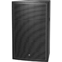
CPL 15+ - Loudspeaker CREST AUDIO - Free user manual and instructions
Find the device manual for free CPL 15+ CREST AUDIO in PDF.


| Type | Passive 2-way Loudspeaker System |
| Woofer | 15" (381 mm) with 3" (76 mm) voice coil |
| HF Driver | 1" (25.4 mm) Neodymium compression driver with 1.7" (44 mm) voice coil |
| Power Handling (Continuous) | 500 Watts |
| Power Handling (Program) | 1000 Watts |
| Power Handling (Peak) | 2000 Watts |
| Nominal Impedance | 8 Ohms |
| Sensitivity (1W/1m) | 97 dB |
| Maximum SPL (Continuous) | 125 dB @ 1m |
| Maximum SPL (Peak) | 131 dB @ 1m |
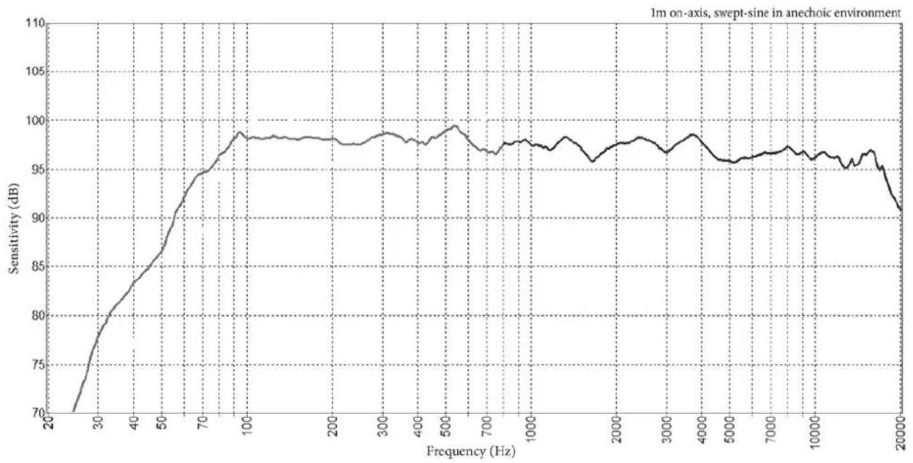
| Frequency Response (±3 dB) | 66 Hz - 17.8 kHz |
| Frequency Range (-10 dB) | 47 Hz - 20 kHz |
| Coverage Pattern (H x V) | 90° x 60° (Rotatable Horn) |
| Input Connections | 2 x 4-pin twist-lock, 1 x 4-pin Euroblock (Loop Through) |
| Enclosure Material | 18 mm Plywood with textured polyurea paint |
| Grille | Heavy-duty steel backed with acoustic foam |
| Mounting Points | 16 x M8 threaded inserts (12 general + 4 for Versamount 70) |
| Dimensions (H x W x D) | 27.36" x 17.36" x 17.52" (695 x 441 x 445 mm) |
| Net Weight | 67.2 lbs (30.5 kg) |
| Recommended High-Pass Filter | 40 Hz, 12 dB/octave Butterworth |
| Routine Cleaning | Use a soft dry cloth; avoid solvents and moisture |
| Safety Warning | Requires certified rigging; hearing protection recommended; do not suspend from single point |
| Spare Parts & Service | Contact Crest Audio for replacement parts and servicing |
Frequently Asked Questions - CPL 15+ CREST AUDIO
User questions about CPL 15+ CREST AUDIO
0 question about this device. Answer the ones you know or ask your own.
Ask a new question about this device
Download the instructions for your Loudspeaker in PDF format for free! Find your manual CPL 15+ - CREST AUDIO and take your electronic device back in hand. On this page are published all the documents necessary for the use of your device. CPL 15+ by CREST AUDIO.
USER MANUAL CPL 15+ CREST AUDIO
Passive 2-way Loudspeaker System

natural_image
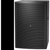
Black speaker chamber with mesh grille and logo (no visible text or symbols)Operating Manual
| Model Number or Name: |
| Date of Purchase: |
| Serial Number: |
| Dealer Name: |
Crest Audio ^® CPL ^TM 15 ^+
The Crest Audio CPL 15^+ is a passive two-way loudspeaker designed for music playback, public address and live performance reinforcement applications.
The CPL 15 ^+ can be utilized for both permanent installations and portable live sound applications. Perfect for public address, monitoring and background audio reinforcement purposes typically required in houses of worship, clubs, bars/restaurants, retail outlets plus education and corporate meeting facilities or anywhere high quality audio distribution is required.
The CPL 15^+ is equipped with a premium 15 inch woofer having a 3 inch voice coil together with a 1 inch exit Neodymium compression driver known for its smooth frequency response and non-fatiguing mid range. Directivity pattern of the loudspeaker is measured at 90^ horizontal and 60^ vertical providing a wide yet well controlled audio coverage. An internal advanced crossover network maintains EQ and driver protection. Impedance of the loudspeaker is 8 Ohms allowing for easy daisy chaining. Connectivity is made via either looping 4-pin twist-lock or 4-pin Euroblock connectors.
The CPL 15^+ enclosure is built from prime-grade 18 mm plywood that offers sturdy mechanical and low resonant electro-acoustic characteristics together with a heavy-duty steel grille backed with acoustic foam to ensure maximum protection of the internal components. The loudspeaker is equipped with a total of 16 threaded suspension points offering multiple mounting options for various applications. Available in durable black and white finish.
Features
• Passive two-way loudspeaker
- Premium 15" woofer, 3" voice coil
- 1" Neodymium compression driver, 1.7" voice coil
• Continuous power handling: 500 Watts
• Nominal impedance: 8 Ohms
• Coverage pattern (HxV): 90° x 60° Rotatable Horn
- Connectors: 2 x 4-pin twist-lock & 4-pin Euroblock
- 2 + / 2 - Loop Through
• Advanced crossover network
- Tweeter protection
• 18 mm Plywood construction
- Textured polyurea paint
- 12 x M8 suspension points (3 top, 3 bottom, 2 each side, 2 rear)
- 4 x M8 suspension points for Peavey® Versamount™ 70
• Available in Black and White
Configuration: 2-way passive speaker
Power Handling*: 500 Watts Continuous, 1,000 Watts Program, 2,000 Watts Peak
*To reach the rated power, there must be an infrasonic filter set to 40 Hz, 12 dB / Octave Butterworth minimum filtering. If the CPL 15^+ is used with a crossover for a Subwoofer, then the high pass section needs to meet this criteria at a minimum. A higher frequency and/or filter slope is acceptable.
Nominal Impedance: 8 Ohms
Sensitivity (1W/1m): 97 dB
Maximum SPL (1m): 125 dB @ 500 Watts; 131 dB @ 2,000 Watts Peak
Frequency Response*: 66 Hz - 17.8 kHz, ±3 dB
*1m on-axis, swept-sine in anechoic environment
Frequency Range*: 47 Hz - 20 kHz, -10 dB
*1m on-axis, swept-sine in anechoic environment
Box Tuning Frequency: 44 Hz
Nominal Coverage Pattern (-6 dB): 90° H x 60° V
LF Driver: 1 x 15" (381 mm) Woofer - Crest Audio CPL15A
LF Driver Voice Coil: 3" (76 mm)
HF Driver: 1 x 1" (25.4 mm) Neodymium Compression Driver - Crest Audio HF44FP1
HF Driver Voice Coil: 1.7" (44 mm)
Input Connections: 2 x 4-pin twist-lock (NL-4 style) & 1 x 4-pin Euroblock
Input, Pin 1+ = (+) positive; Pin 1- = (-) negative / Loop Through, Pin 2+ = (+) positive; Pin 2- = (-) negative
Enclosure Material: 0.7" (18 mm) Plywood
Finish: Textured polyurea paint, available in Black & White
Black Finish: RAL: 9004 Signal Black (Pantone: Black 6)
White Finish: RAL: 9003 Signal White (Pantone: 705)
Front: Full-coverage perforated steel grille, backed with acoustically neutral foam
Mounting Provisions: Twelve (12) M8 suspension points (3 top, 3 bottom, 2 left, 2 right, and 2 rear) and additional set of four (4) M8 mounting points rear for optional Peavey Versamount 70
Overall Dimensions (HWD):
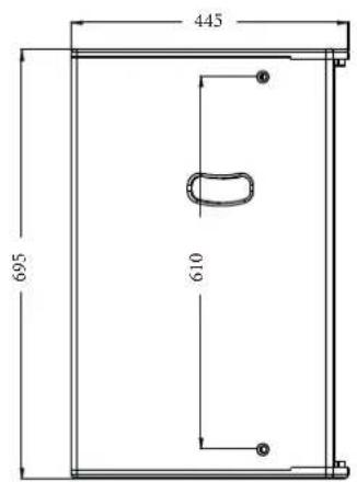
Front - 27.36" x 17.36" x 17.52" (695 x 441 x 445 mm)
Rear - 27.36" x 11.92" x 17.52" (695 x 303 x 445 mm)
Net Weight: 67.2 lbs (30.5 kg)
CAUTION
Before attempting to suspend this speaker, consult with a certified structural engineer. Speaker can fall from improper suspension, resulting in serious injury and property damage. Do not suspend or mount any other product or device from this enclosure! Use only the correct mating hardware. All associated rigging is the responsibility of others. Maximum enclosure angle 30 degrees.
Whenever possible, in addition to the nominal primary mounting method, use a suitable safety chain or wire rope attached to one of the other groups of fly point inserts, and firmly attached to a suitable structural member as indicated by a certified structural engineer.
We recommend the use of thread-locker at the insert point bolts, so the bolts cannot vibrate loose. Never transport the cabinet using the array bracket or other mounting brackets as a structural member, while the cabinet is mounted on an array bracket or other mounting bracket and unsupported otherwise, as this may unduly stress the mounting inserts.
This Crest Audio loudspeaker should be suspended overhead only in accordance with the procedures and limitations specified in the User's Manual and possible manual update notices. This system should be suspended with certified rigging hardware by an authorized rigging professional and in compliance with local, provincial or national suspension ordinances.
INSTALLATION
A total of sixteen (16) M8 1.25 mm per thread threaded mounting suspension points (3 top, 3 bottom, 2 left, 2 right, and 6 rear) are provided. These are plugged with a hex key beveled head bolts.
Twelve of these sixteen mounting suspension points are for use with forged shoulder machinery eyebolts (3 top, 3 bottom, 2 left, 2 right, and 2 rear) and should be an M8 size, 1.25 mm per thread, and must conform to at least DIN 580 or ASTM A489, or whatever local, provincial or national suspension ordinances or regulations may additionally require. Eyebolts must be used in groups of 3 or 4, never use just one or two eyebolts to hang the speaker overhead.
An additional set of four (4) M8 1.25 mm per thread threaded mounting suspension points are provided at the rear center of the cabinet for the optional Versamount 70 ceiling or wall-mount bracket.
WARNING
The CPL 15^+ passive 2-way loudspeaker system is very efficient and powerful! This sound system can permanently damage hearing! Use extreme care setting the overall maximum loudness!
The apparent sound level of the CPL 15^+ can be deceiving due to its clear, clean sound output. The lack of distortion or obvious distress can make the sound level seem much lower than it actually is. This system is capable of sound pressure levels (SPL) in excess of 131 dB at 1 meter from the speaker!
Installation methods for optional mounting accessories
Note: U-Bracket, Peavey Versamount 70, and Pole Mount Adapter are not included. These are optional accessories and need to be ordered separately.
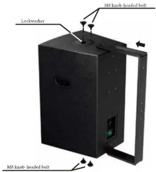
Installation Method 1 - U-Bracket

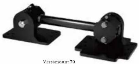
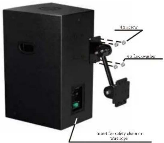
Installation Method 2 - Versamount 70
natural_image
Mechanical assembly with two black components and a central shaft, labeled 'Versamount 70' below (no other text or symbols)Installation Method 3 - Pole Mount Adapter


Grouping of insert sets for CPL 15 ^+
Group A
A set of three (3) M8 inserts on the top, designed to hang the cabinet using the proper eyebolts. The rearmost insert can be used as a pull-back point OR an additional fly point.
Group B
A set of three (3) M8 inserts on the bottom, designed to hang the cabinet using the proper eyebolts. The rearmost insert can be used as a pull-back point OR an additional fly point.
Group C
A set of two (2) M8 inserts on either side, designed to hang the cabinet using the proper eyebolts.
Group D
A set of two (2) M8 inserts on the rear, designed for the use of pull-back angling of the cabinet when using the other Groups A, B, or C, using the proper eyebolts.
Group E
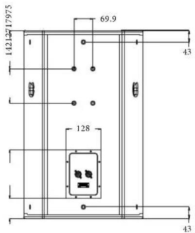
A set of four (4) M8 inserts on the rear, designed to be used with the Peavey Versamount 70 ceiling or wall-mount bracket. These are spaced apart side-to-side on the centers by 69.9 mm, and apart 127 mm top-to-bottom on the centers, and the group of four is located centered on the rear side-to-side, and just below the handle.
Group F
The M8 inserts at the center of the U-Bracket mounting plates on the top and bottom, normally used for the U-Bracket retention, but can be used for safety chain/wire rope if necessary.
For Group A, B and C, always use the inserts at a minimum as a pair; NEVER use just one insert to fly a cabinet! Group D can use just one for pull-back, or for safety wire/chain attachment, as long as there are two other eyebolts on a given cabinet wall used for primary suspension points.
For Group E, always use all four inserts of a given group as a set; NEVER use just one insert to fly a cabinet! The four insert groupings are meant to have all four inserts used at once within a group.
For Group F, always use both inserts with the appropriate hardware to mount a model specific Crest Audio U-Bracket. These inserts can also be used, if necessary, as safety points for a chain or rope attachment point when other mounting methods are being used.
Specifications for insert mating hardware
Group A, B, C, and Group D should use M8 forged steel shoulder-type lifting eyebolt, which meet the requirements of DIN 580 or ASTM A489, or whatever local, provincial or national suspension ordinances or regulations may additionally require. They should at a minimum be used in pairs for the primary suspension points, and in conjunction with a pull-back/aiming adjustment point insert, using M8 eyebolts of a similar specification. The length of the threaded shank on the eyebolts should not exceed 20 mm (approximately 3/4"), so that it does not engage the interior of the cabinet's sound absorbing lining. Thread pitch: 1.25 mm per thread.
Group E should use M8, grade 8.8 or better, 1.25 mm per thread, metric bolt, that does not penetrate the cabinet past the cabinet surface more than exceed 20 mm (approximately 3/4"). When using a Peavey Versamount 70 ceiling or wall-mount bracket and lockwasher, the length of the bolt should not exceed 30 mm (approximately 1.125").
Group F should use M8, grade 8.8 or better, 1.25 mm per thread, metric bolt, that does not penetrate the cabinet past the cabinet surface more than 20 mm (approximately 3/4").
Notes on specific mounting methods using optional accessories
Mounting Method 1 - U-Bracket
Use the large handled knob-headed bolts to mate the U-Bracket to the cabinet, placing lockwashers between the bracket and bolt. See diagram above. Determine the angle that the cabinet needs to be relative to the U-Bracket, and position the cabinet to that angle, and screw-in a small handle knob-headed bolt through the threaded angle-set hole in the bracket into one of the 24 angle location holes on the cabinet. Use the hole nearest the angle desired.
For permanent installation, the large handled knob-headed bolts can be substituted for with hex head bolts by using the specifications above (Group F). It is then recommended that thread-locker be used. Using hex head bolts with thread-locker will remove the possibility for someone to attempt to unscrew the knob-headed bolts by hand to vandalize or otherwise alter the cabinets mounting.
If using the U-Bracket with the cabinet pointing straight out (bracket rear parallel to the rear of the cabinet), then use of the NL-4 twist-lock connection is best made before locking the angle into place and using thread-locker. Offset the cabinet till the NL-4 jack clears the bracket, and plug it up, then rotate the cabinet into the final position, etc.
Mounting Method 2 - Peavey Versamount 70
Instructions for use are included with the Versamount 70, and for permanent installation, once the angles have been finalized, use thread-locker on the four mounting bolts with lockwashers. The bolts for this method are Group E.
Mounting Method 3 - Pole Mount Adapter
This adapter allows use of the cabinet with a speaker stand (also referred to as a tripod stand) for temporary portable use. It is designed for use with a standard 1 3/8" (35 mm) diameter stand pole. This adapter is only provided for use with the stand pole that is aligned basically straight up, no tilt should be present, or this could cause an unsafe situation.
Install the adapter by threading it into the center insert of the mounting plate on the bottom of the CPL+ cabinet. At some point, the adapter will no longer screw in any further. Then, find the nearest threaded hole on the adapter mounting plate that line's up with one of the 24 holes on the cabinet mounting plate (it may be necessary to back off the adapter slightly to line the holes up), and screw in one of the knob-headed bolts supplied with the adapter. Two of the knob-headed bolts are provided, but only one needs to be screwed into position for the best fit of the adapter, the other is provided as a spare.
Loosen the pole tightening knob till the threads clear the inside of the pole tunnel of the adapter, and place the cabinet onto the stand pole, then tighten the pole tightening knob firmly once the speaker is aimed horizontally as desired.
DO NOT TILT THE STAND/POLE TO TRY AND AIM THE CABINET VERTICALLY, THIS TYPE OF USE OF THE STAND POLE ADAPTER MOUNT IS NOT ALLOWED!
When using stands or poles, be sure to follow these precautions:
Check the stand or pole specs to make sure that it can support the weight of the CPL+ model, and observe all safety precautions stated by the stand manufacturer, including the maximum height and/or weight the stand is rated for.
Always place the stand on a flat, level and stable surface, and be sure to fully extend the stand legs as per the stand manufacturer's instructions.
Try to make sure that the stand legs are oriented for the least danger of tripping to those in the vicinity of the stand. Never block a doorway or hallway with the legs of a stand.
Try to route cables so that people will not trip over them, or tip the speaker over. Use of duct tape, cable channels or guards, or other appropriate tie-down/cover-up devices should be carefully considered and implemented.
When installing or de-installing the speaker on the stand, it is a good practice to have a helper if possible. It can be hard to “thread the needle” and mate the stand cup to the stand pole while holding the CPL+ speaker system at arm’s length. It is also helpful if someone holds the speaker stand and pole down while the CPL+ speaker system is removed from the stand pole, this prevents the CPL+ speaker from pulling the pole up with it.
When using stands outdoors, never attach banners or flags to the stands or the CPL+ speaker system, strong winds may cause the speaker to blow over. If there is a possibility of windy conditions, then it may be prudent to consider weighting or locking down the stand legs to prevent the CPL+ speaker system from being blown over.
Use of the CPL+ Pole Mount Adapter with a subwoofer and associated pole:
Always be sure to place the subwoofer used in this manner on a flat, level and stable surface. Follow the manufacturer's instructions regarding how high the pole can be for a given size and weight of cabinet on top. Many of the precautions mentioned above for speaker stands will also apply to this type of use.
CPL+ Series Input & Loop Through Schematics
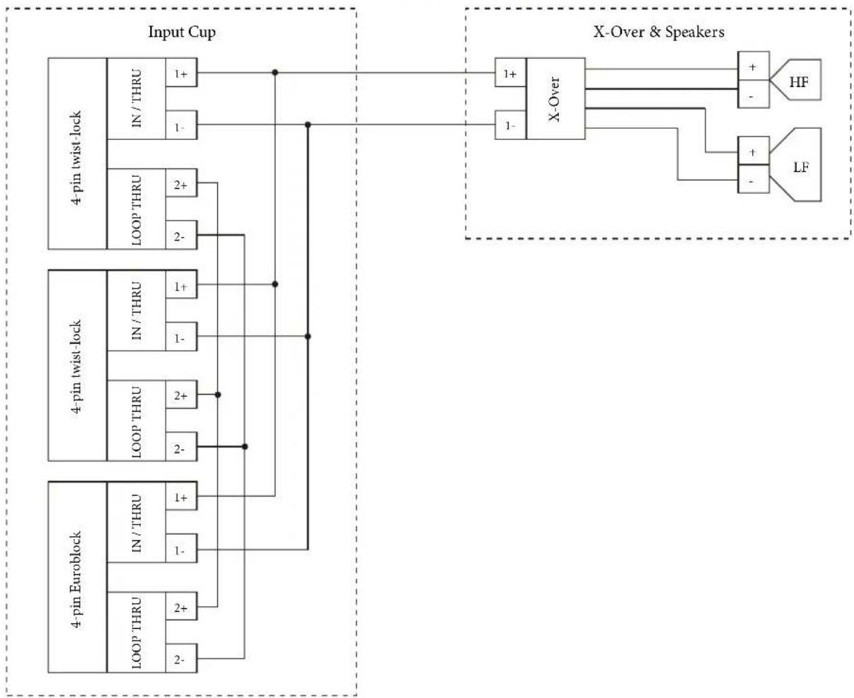
flowchart
graph TD
    subgraph_Input_Cup["Input Cup"]
        A["4-pin twist-lock"] --> B["IN / THRU"]
        A --> C["LOOP THRU"]
        B --> D["1+"]
        B --> E["1-"]
        C --> F["2+"]
        C --> G["2-"]
    end

    subgraph X_Over &Speakers["X-Over & Speakers"]
        H["X-Over"] --> I["HF"]
        H --> J["LF"]
        H --> K["+"]
        H --> L["-"]
    end

    subgraph Output
        M["4-pin twist-lock"] --> N["IN / THRU"]
        M --> O["LOOP THRU"]
        M --> P["2+"]
        M --> Q["2-"]
    end

    subgraph Output_Skew
        R["4-pin Euroblock"] --> S["IN / THRU"]
        R --> T["LOOP THRU"]
        R --> U["2+"]
        R --> V["2-"]
    end

    style Input_Cup fill:#f9f,stroke:#333
    style X_Over &Speakers fill:#ccf,stroke:#333
CPL+ Series Loop Through System Schematics
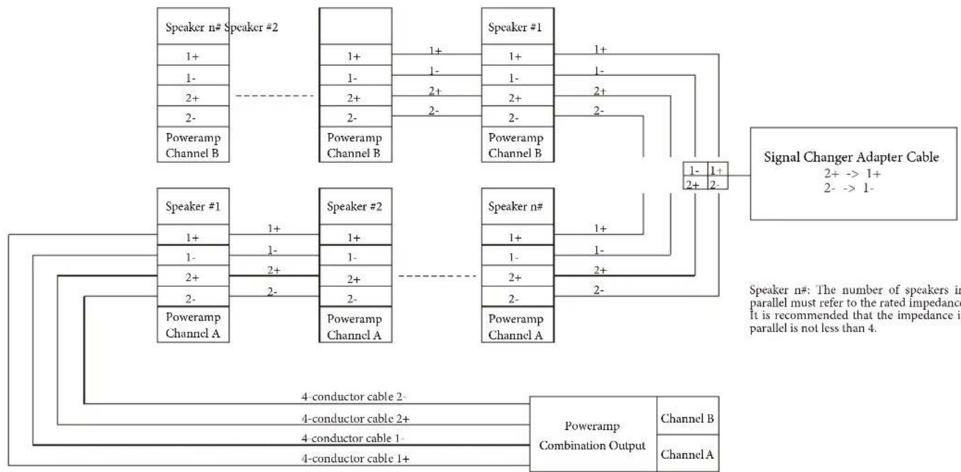
flowchart
graph TD
    subgraph_Speaker_1["Speaker #1"]
        A1["1+"] -->|1+| B1["1-"]
        A2["1-"] -->|1-| B2["2+"]
        A3["2-"] -->|2+| B3["2-"]
        A4["2-"] -->|2-| B4["Poweramp Channel A"]
    end

    subgraph_Speaker_2["Speaker #2"]
        B1["1+"] -->|1+| C1["1-"]
        B2["1-"] -->|1-| C2["2+"]
        B3["2-"] -->|2+| C3["2-"]
        B4["2-"] -->|2-| C4["Poweramp Channel B"]
    end

    subgraph_Speaker_3["Speaker #3"]
        C1["1+"] -->|1+| D1["1-"]
        C2["1-"] -->|1-| D2["2+"]
        C3["2-"] -->|2+| D3["2-"]
        C4["2-"] -->|2-| D4["Poweramp Channel A"]
    end

    subgraph_Signal_Changer_Cable["Signal Changer Adapter Cable"]
        D1["1-"] -->|1+| E1["2+"]
        D2["2-"] -->|2-| E1
    end

    F1["4-conductor cable 2-"] --> G1["4-conductor cable 2+"]
    F2["4-conductor cable 1-"] --> G2["4-conductor cable 1+"]
    F3["4-conductor cable 1+"] --> G3["Poweramp Combination Output"]
    G3 --> H1["Channel B"]
    G3 --> H2["Channel A"]
    style Speaker_1 fill:#f9f,stroke:#333
    style Speaker_2 fill:#f9f,stroke:#333
    style Speaker_3 fill:#f9f,stroke:#333
    style Signal_Changer_Cable fill:#ccf,stroke:#333
Unit: mm




The loudspeaker shall consist of a 15 inch (381 mm) low frequency transducer with 3 inch (76 mm) voice coil and one 1 inch (25.4 mm) exit Neodymium compression driver with a 1.7 inch (44 mm) voice coil and a frequency dividing network installed within the enclosure.
Performance specifications of a typical production unit shall be: Measured sensitivity SPL at 1 m (3.3ft) with 2.83V input, shall be 97 dB-SPL. Usable frequency response shall extend from 47 Hz to 20 kHz (10 dB below rated sensitivity, in full space, with no external equalization). Nominal impedance shall be 8 Ohms. Rated power capacity shall be at least 500 Watts continuous power and 2,000 Watts peak power, defined as 6 dB above a test signal of filtered random noise.
The system shall be protected against damage from occasional over-powering limiting the power to the network and transducers. The compression driver shall be capable of even coverage at a nominal 90^ horizontal through 60^ vertical distributed pattern. The horn shall be rotatable.
The enclosure shall be constructed from prime-grade 18 mm plywood. The loudspeaker shall be equipped with a total of sixteen (16) suspension points. The grille shall be of heavy-duty steel backed with acoustically transparent foam. The external wiring shall be via either two 4-pin twist-lock or one 4-pin Euroblock connectors. The loudspeaker shall be 27.36 inches (695 mm) high by 17.36 inches (441 mm) wide by 17.52 inches (445 mm) deep weighing 67.2 pounds (30.5 kg). The finish shall be a paintable lightly textured black or white.
The loudspeaker shall be the Crest Audio CPL 15 ^+ .
Frequency Response
line
| Frequency (Hz) | Sensitivity (dB) | | -------------- | ---------------- | | 20 | 70 | | 30 | 78 | | 40 | 83 | | 50 | 87 | | 70 | 94 | | 100 | 98 | | 200 | 98 | | 300 | 98 | | 400 | 98 | | 500 | 99 | | 700 | 97 | | 1000 | 98 | | 2000 | 97 | | 3000 | 97 | | 4000 | 98 | | 5000 | 96 | | 7000 | 97 | | 10000 | 96 | | 20000 | 91 |Impedance
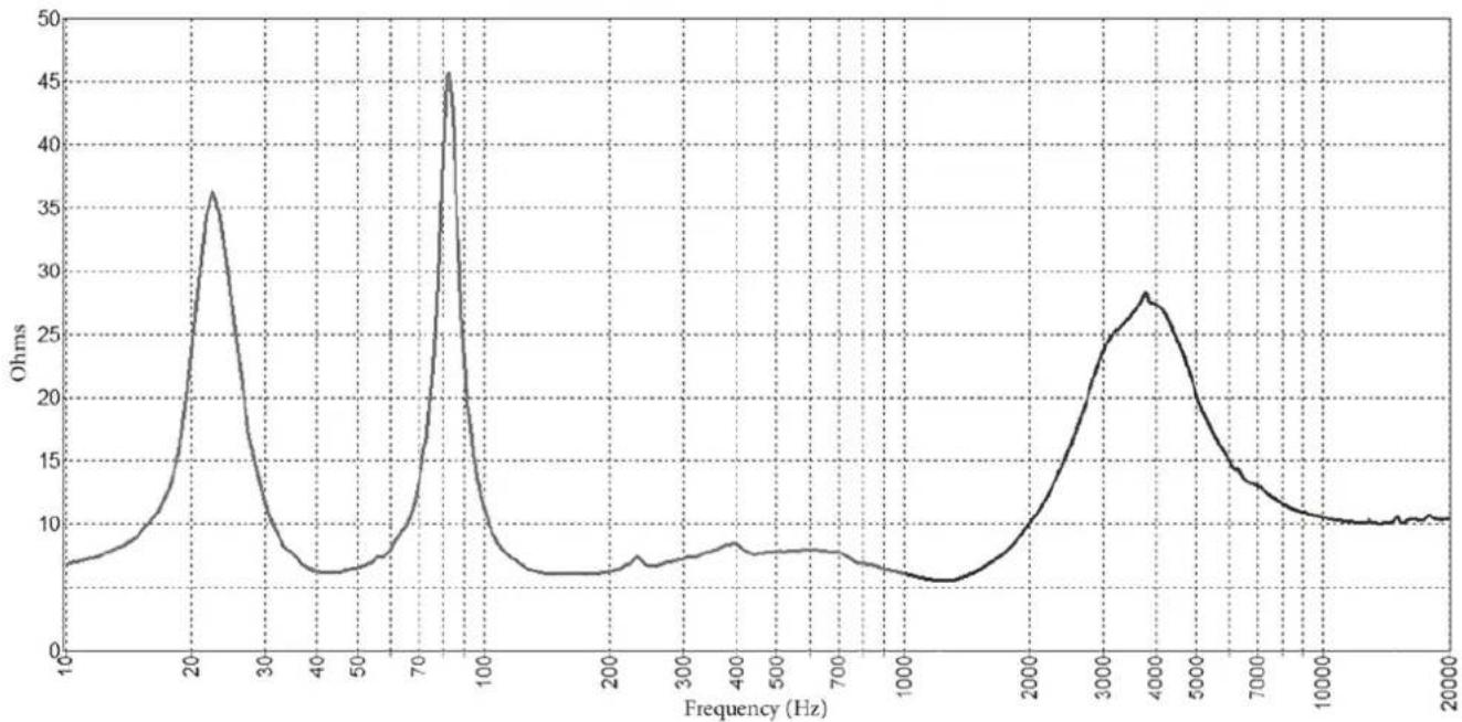
line
| Frequency (Hz) | Ohms | | -------------- | ---- | | 10 | 8 | | 20 | 36 | | 30 | 10 | | 40 | 7 | | 50 | 8 | | 60 | 10 | | 70 | 20 | | 80 | 45 | | 90 | 20 | | 100 | 8 | | 200 | 7 | | 300 | 8 | | 400 | 9 | | 500 | 8 | | 600 | 8 | | 700 | 8 | | 800 | 7 | | 900 | 7 | | 1000 | 7 | | 2000 | 10 | | 3000 | 25 | | 4000 | 28 | | 5000 | 25 | | 6000 | 20 | | 7000 | 15 | | 8000 | 12 | | 9000 | 11 | | 10000 | 10 | | 15000 | 10 | | 20000 | 10 |
www.crestaudio.com

Features and specifications subject to change without notice.
Crest Audio 5022 HWY 493 N. Meridian, MS 39305 (601) 483-5365 FAX (601) 486-1278

Logo referenced in Directive 2002/96/EC Annex IV (OJ(L)37/38,13.02.03 and defined in EN 50419: 2005
The bar is the symbol for marking of new waste and is applied only to equipment manufactured after 13 August 2005
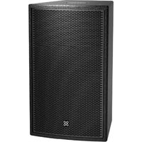
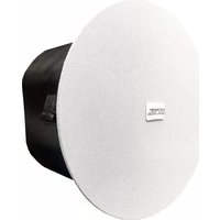

- Crest Audio ® CPL TM 15 +
- Features
- Configuration: 2-way passive speaker
- Nominal Impedance: 8 Ohms
- CAUTION
- INSTALLATION
- WARNING
- Installation methods for optional mounting accessories
- Grouping of insert sets for CPL 15 +
- Group A
- Group B
- Group C
- Group D
- Group E
- Group F
- Specifications for insert mating hardware
- Notes on specific mounting methods using optional accessories
- Mounting Method 1 - U-Bracket
- Mounting Method 2 - Peavey Versamount 70
- Mounting Method 3 - Pole Mount Adapter
- When using stands or poles, be sure to follow these precautions:
- Use of the CPL+ Pole Mount Adapter with a subwoofer and associated pole:
Brand : CREST AUDIO
Model : CPL 15+
Category : Loudspeaker