
SCE1100ADB - Heating SVAN - Free user manual and instructions
Find the device manual for free SCE1100ADB SVAN in PDF.


| Product type | Electric convector heater |
| Power | 2000 W |
| Voltage | 220-240 V / 50-60 Hz |
| Dimensions (HxWxD) | 400 x 600 x 200 mm |
| Weight | 5 kg |
| Heating levels | 2 (1000 W / 2000 W) |
| Thermostat | Adjustable electronic thermostat |
| Safety features | Overheat protection, tip-over switch |
| Energy class | C |
| Color | White |
| Power cord length | 1.5 m |
| Controls | Electronic panel with LED display |
| Timer | 24-hour programmable timer |
| Remote control | Not included |
| Wheels | Yes (4 castors) |
| IP rating | IP24 (splashproof) |
| Noise level | ≥ 35 dB |
| Special modes | Frost protection, Eco mode |
| Cleaning | Wipe with a damp cloth, avoid abrasives |
| Maintenance | No user-serviceable parts; contact service center |
| Warranty | 2 years |
Frequently Asked Questions - SCE1100ADB SVAN
User questions about SCE1100ADB SVAN
0 question about this device. Answer the ones you know or ask your own.
Ask a new question about this device
Download the instructions for your Heating in PDF format for free! Find your manual SCE1100ADB - SVAN and take your electronic device back in hand. On this page are published all the documents necessary for the use of your device. SCE1100ADB by SVAN.
USER MANUAL SCE1100ADB SVAN
Modelo: SCE1100ADB
SCE1300ADB
ÍNDICE DE CONTENIDOS
TÍTULO
PÁGINA
Sin humo y fuego


4. MÉTODOS DE USO
4.3 Deje de usarlo
Domestic Instantaneous Gas Water Heater
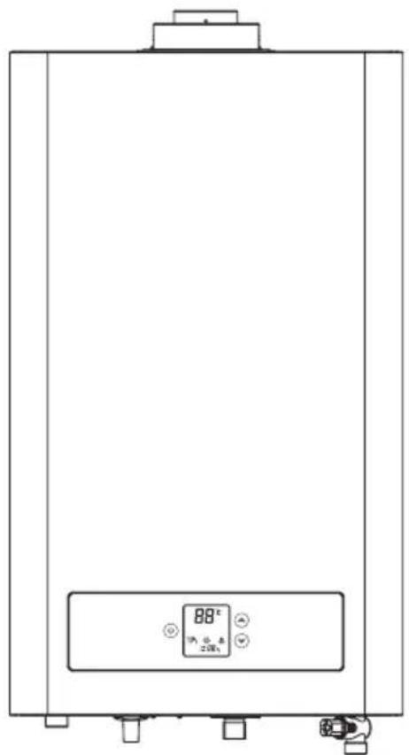
Model: SCE1100ADB SCE1300ADB
TABLE OF CONTENTS
TITLE PAGE
- CAUTIONS....2
- PRODUCT INTRODUCTION ....4
- UNIT INSTALLATION ....8
- METHODS OF USING 17
- MAINTENANCE ....21
- TROUBLESHOOTING ....21
The heater corresponds to requirements of CE standard, and accord with the following directives:
●(EU)2016/426 ;legal Facilities directives of the Member States for Natural Gas Installation.
●2014/30/EU ; Directives for the electromagnetic compatibility.
- EN 26; water heaters in the sanitary equipped with atm ospheric gas burner with natural gas as fuel.
- EN 50165;non-electronic electrical apparatuses for home use and other similar uses.
- EN 55014; electromagnetic compatibility. Requirements of electromagnetic appliances, electronic tools and other similar apparatuses.
●EN 61000-3; Electromagnetic compatibility (CEM)
●EN 60335-1; non-electronic heatingapparatuses for home use and other similar uses
1. CAUTIONS
1.1 Special Cautions
When the water heater is working, gas combustion would consume a large amount of oxygen and exhaust much carbon monoxide. In view of the great harm to the human health or even death caused by excessive carbon monoxide inhalation, the company sincerely advises all users that:
- The water heaters must be correctly installed and used according to the requirements of this manual.
- The water heater must be installed in rooms, do not install outdoors.
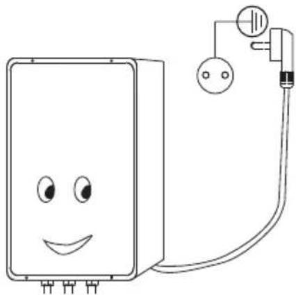
- The power socket must be reliably earthed.
- This appliance can be used by children aged from 8 years and above and persons with reduced physical, sensory or mental capabilities or lack of experience and knowledge if they have been given supervision or instruction concerning use of the appliance in a safe way and understand the hazards involved. Children shall not play with the appliance.
Cleaning and user maintenance shall not be made by children without supervision.
If the supply cord is damaged, it must be replaced by the manufacturer, its service agent or similarly qualified persons in order to avoid a hazard.
This appliance is intended for domestic use only.

WARNING
We shall not be liable for any accident arising from unauthorized disassembly or failure to operate on this instruction manual.
1.2 Prevention of Gas Accident
- Confirmation of category of gas: the category of gas used must be identical to that specified on the nameplate of the water heater without prior permission, and no forced use of different categories of gas.
- Make sure that the burner has gone out after use, and don't forget to close the main gas valve.
- Examine the leak tightness of each joint and pipeline frequently. Under normal conditions, the rubber pipes shall be replaced once every year.
- For the users of liquefied petroleum gas, if it is found that the flame of the water heater is high one minute and low the next, the decompression valve at the exit of gas vessel maybe breaks down. At this moment, stop use of the water heater and replace with a qualified decompression valve.
- For the users of natural gas, when the flame is found abnormal (due to instability of gas pressure in the pipelines), stop using of the water heater temporarily. If it is forced to be used, the heater may be damaged, even resulting in an accident.
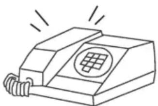
- If the leakage is found, don't ignite or operate the switches of any kinds of electrical appliances, and don't make calls. Close the main gas valve immediately, open all the doors and windows to exhaust the leaked gas outdoors automatically, stop using the water heater, and contact with the maintenance department or the gas company.
- The water heaters are strictly forbidden to work with failure. If a heater breaks down, please contact with the repair center of our company in time.
- This water heater can be only used for hot water supply or shower. Do not use it for other purposes.

No smoke and fire Close gas valve
1.3 Guards Against Fire
- It is absolutely forbidden to leave home or go to sleep under the circumstance that a water heater hasn't gone out.
- No inflammable goods placed near the fume hood of a water heater. The air intake and the exhaust exit shall not be covered by towels, clothing, etc.


1.4 Other Cautions
- Preventing scald due to overheat: If the use of a water heater is restored immediately after the hot water valve is closed, do not contact the hot water until several seconds later, to prevent the skin burned due to too high transient temperature rise.
- Improper for drinking water supply: since there is water stored in a water stored in a water heater for a long time, the hot water supplied by the heater can only be used for general purposes, but not suitable for drinking.
• Prevention of electric accident
① Take the electrical plug out before chean or maintenance
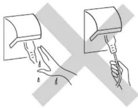
② Do not touch the receptacle with a wet hand, as this will have the risk of electric shock.
③ Please insert the power supply plug securely on the plug. A dusty or loose plug might be the cause of an electric shock or fire.
④ Do not pull out the plug by pulling the power cord, as this might break the internal wire of the cord and further lead to wire heating or a fire.
⑤ This unit must be connected to a ground wire. Make sure the ground wire is connected properly.
- During ignition, it is strictly forbidden to let the eyes close to the observation hole to examine the ignition conditions. The distance between eyes and observation hole shall be larger than 300mm.
2. PRODUCT INTRODUCTION
2.1 Technical Performance Parameters (Table 1)
| Model | SCE1100ADB | SCE1300ADB | |||||||||
| CE-Pin | 2806DN0131 | ||||||||||
| Power Consumption | W 45 | 45 45 | 45 | ||||||||
| Rated Voltage | V.ac | 230~ 230~ 230~ | 230~ | ||||||||
| Frequency | Hz | 50 50 50 50 | |||||||||
| Gas | |||||||||||
| Gas Category | I3P(37) | I3B/P(30) | I3+(28-30/37) | I 2H | I3P(37) | I3B/P(30) | I3+(28-30/37) | I 2H | |||
| Gas Type | G31 | G30 | G30/G31 | G20 | G31 | G30/G31 | G30 | G31 | G20 | ||
| Gas pressure | mbar | 37 | 30 | 28-30 | 37 | 20 | 37 | 30 | 28-30 | 37 | 20 |
| Power | |||||||||||
| Nominal Heat Input(Q) | kW | 22 | 22 | 26 | 26 | ||||||
| Nominal Useful Output | kW | 19.2 | 19.2 | 23.1 | 22.2 | ||||||
| Minimum Heat Input | kW | 9.5 | 9.5 | 11.5 | 11.5 | ||||||
| Minimum Useful Output | kW | 8.5 | 8.5 | 10.3 | 10.3 | ||||||
| Efficiency of energy sources | 85% | 85% | 85.9% | 85.9% | |||||||
| Water supply pressure | |||||||||||
| Max. water pressure | bar | 10 | 10 | 10 | 10 | ||||||
| Min. water pressure | bar | 0.2 | 0.2 | 0.2 | 0.2 | ||||||
| Max. water pressure | MPa | 1.0 | 1.0 | 1.0 | 1.0 | ||||||
| Min. water pressure | MPa | 0.02 | 0.02 | 0.02 | 0.02 | ||||||
| Max.waterflow(2bar) | L/min | 13.0 | 13.0 | 13.0 | 13.0 | ||||||
| Min.waterflow(2bar) | L/min | 8.0 | 8.0 | 8.0 | 8.0 | ||||||
| Connections | |||||||||||
| Gas connection | inch | 1/2" | 1/2" | 1/2" | 1/2" | ||||||
| Cold water connection | inch | 1/2" | 1/2" | 1/2" | 1/2" | ||||||
| Hot water connection | inch | 1/2" | 1/2" | 1/2" | 1/2" | ||||||
| Flue gas pipe diameter(D) | mm | Φ60-100(C12,C32)/Φ80(B22) | Φ60-100(C12,C32)/Φ80(B22) | ||||||||
| Maximum temperature of exhaust pipe Q Hi ** | °C | 150 | |||||||||
| Flue gas pipe length | |||||||||||
| Max. length of flue pipe | m | 4(for C12/B22)1(forC32) | 4(for C12/B22)1(forC32) | 4(for C12/B22)1(forC32) | 4(for C12/B22)1(forC32) | ||||||
| Min. length of flue pipe | m | 1(for all) | 1(for all) | 1(for all) | 1(for all) | ||||||
| Max. quantity of elbow | pc | 1 | 1 1 | 1 | |||||||
| Net dimensions / net weight | |||||||||||
| Dimensions (L×W×H) | mm | 660x370x213 | 660x370x213 | 660x370x213 | 660x370x213 | ||||||
| Weight | kg | 13.4 | 13.4 | 13.8 | 13.8 | ||||||
| Gross dimensions / net weight | |||||||||||
| Dimensions | mm | 800x435x280 | 800x435x280 | 800x435x280 | 800x435x280 | ||||||
| Weight | kg | 13.85 | 13.85 | 14.6 | 14.6 | ||||||
| Table of nozzle pressure | |||||||||||
| nozzle | |||||||||||
| Diameter of nozzle | mm | Φ0.54 | Φ0.82 | Φ0.54 | Φ0.80 | ||||||
| Quantity of nozzle | unit | 24 | 24 | 30 | 30 | ||||||
| ERP | |||||
| Declare load profile | M | M | XL | XL | |
| Water heating energy efficiency class | A | A | A | A | |
| Water heating energy efficiency ηWH | % | 77.24 | 77.24 | 81.66 | 81.66 |
| Daily gas consumption (Corrected) | kWh | 7.605 | 7.605 | 21.806 | 21.806 |
| Daily electrical consumption (Corrected) | kWh | 0.1168 | 0.1168 | 0.12783 | 0.12783 |
| AEC | kWh | 25 | 25 | 27 | 27 |
| Annual fuel consumption AFC | GJ | 6 | 6 | 18 | 18 |
| NOx | mg/kWh | 54.5 | 38.13 | 46.57 | 23.75 |
| Indoor sound power level LWA | dB | 60 | 60 | 60 | 60 |
| Operation temperature | °C | 35-65 35-65 | |||
| Protection type | IPX4 ( C12/C22 ) / IPX0 (B ) | IPX4 ( C12/C22 ) / IPX0 (B ) | |||
| Type of installation | C12/C22 / B | C12/C22 / B | |||
| Category | Countries | ||||
| I3+(28-30/37) | BE, CH, CY, CZ, ES, FR, GB, GR, IE, IT, LT, LU, LV, PT, SI, SK, TR | ||||
| I3B/P(30) | AL, BA, BE, BG, CY, CZ, DK, EE, FI, FR, GB, GR, HR, HU, IT, LT, LU, LV, MD, MK, MT, NL, NO, RO, RS, RU, SE, SI, SK, TR, UA | ||||
| I3P(37) | BE, CH, CZ, ES, FR, GB, GR, HR, IE, IT, LT, NL, PL, PT, SI, SK, TR | ||||
| I2H | AL, AT, BA, BG, CH, CY, CZ, DK, EE, ES, FI, GB, GE, GR, HR, IE, IT, LT, LU, LV, MD, MK, MT, NO, PT, RO, RS, RU, SE, SI, SK, TR, UA | ||||
| II2R3R | CZ, DE, DK, EE, ES, FR, GR, IT, NO, PT, SI | ||||
| II2H3B/P | AT, CH, CY, CZ, DK, EE, FI, GR, HR, IT, LT, NO, RO, SE, SI, SK, TR | ||||
| II2H3P | AT, CH, CZ, ES, FR, GB, GR, HR, IE, IT, LT, PT, SI, SK | ||||
| II2H3+ | CH, CY, CZ, ES, GB, GR, IE, IT, LT, PT, SI, SK, TR | ||||


WARNING
The specifications given on the nameplate shall be taken as the standard for special category of gas. Re-equipment or changing into other gas types is not allowed!
2.2 Internal Structural Diagram

Note: The illustration is a reference image, your device may differ
2.3 Functional Features
- Sealed Design: the air inlet and exhaust are completely isolated from the air in the room, so the water heater can be installed in the bathroom.
- Automatic Adjustment Of Water Temperature: advanced proportional regulator, the water temperature can be kept constant at preset temperature (35\~65°C).
- Compulsory Exhaust Device: the waste gases of the water heater can be exhausted outdoor; at the same time, the air necessary for combustion can be inhaled into the heater compulsory. Since the air inlet and exhaust are isolated from the air in the room, the atmospheric environment will not be affected, and the air in the room is kept fresh.
- Ultra-low Water Pressure Starting: the hydraulic pressure for start is as low as 0.02 MPa, the applicable range is wide.
- Flame-out Protection: The water heater will automatically cut off the gas to ensure the gas not leaked when it flames out accidentally during the use.
- Water-gas Interlocked Control: The water heater will automatically stop combustion and shut down when the supply of tap water is suspended or the water valve is shut off.
• Over-pressure Protection: When the pressure of the water supply is too high, the safety valve of the water heater can automatically relieve pressure to avoid any damage to the water heater. - Convenient Removable Water Filter: For areas where the water quality is poor, an easily removable water filter is provided specially for cleaning.
- Brand-new Ultra-thin Appearance Design: Multifunctional color screen display, electronic touch key control, random adjustment of water temperature, automatic constant temperature.
- The Advanced Enclosed Combustion Chamber: Adopts the compulsory proportional combustion mode to control combustion at the optimum state with high thermal efficiency, safe and energy saving.
- Overheat Protection: The water heater will automatically cut off the gas and stop working when the temperature of the water flowing out from the water heater exceeds 90 °C or dry burning occurs.
- Digital display and setting of outlet water temperature, easy and convenient to use.
- Power supply indicator, burning indicator, acousto-optic diplex alarm system to attract attention of the user, safer to use.
- Ultra-large water flow, satisfying multi-point water supply simultaneously.
2.4 Internal wire Diagram

3. UNIT INSTALLATION
3.3 Installation Modes
The combustion air intake grille must locate in a well-ventilated place. To prevent corrosion, it is necessary that the combustion air is free of aggressive substances. Aggressive substances are halogenated hydrocarbons which contain chlorine or fluorine. These substances are found in solvents, paints, adhesives, gasses or liquid-propellants and household cleaners. If these conditions are not able to guarantee, another place should be chosen for the air intake.
This unit must be installed indoors and must not be installed outdoors. Never use this unit when no compulsory gas supply and exhaust pipe is installed.
3.2 Brief Introduction
The water heater must be installed by technicians with professional qualifications for installation. Since the improper installation is liable to failures, the customers shall not install the heater by themselves. Before installation, please make sure again that the category of gas used is identical to that specified on the nameplate. The B22 gas water heater can not be installed in bathroom.


WARNING
The water outlet pipe cannot be connected to the shower nozzle directly; and a water outlet valve must be installed as shown in above illustration.
3.3 Packing List Parameters
| Name and Illustrations Quantity | Quantity Name and Illustrations Quantity | |||
 | Water Heater | 1 |  M6 Expansion Screw M6 Expansion Screw | 1 |
 | Instruction Manual | 1 | 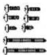 Tapping Screw Tapping Screw | 8 |
 | Plastic Plug | 2 |  Gas pipe connector Sealing Ring Gas pipe connector Sealing Ring | 1 |

- Installation of the unit: Mount the unit upright without inclination according to the dimension show in the following illustration.
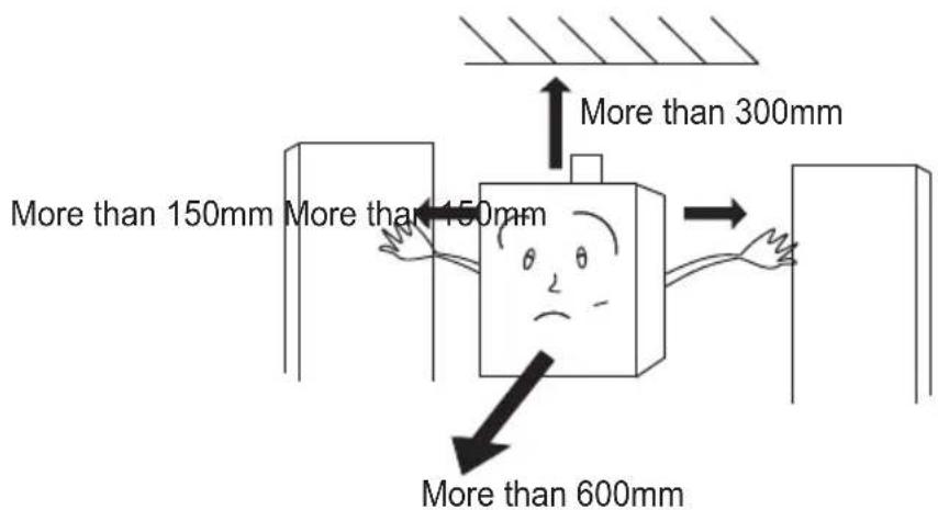
• Type of installation (C12)
- Installation of compulsory gas supply and exhaust pipe of the unit: a. Installation mode of topside exhaust.

As show in the figure below, tap in expansion screws for fixation, hang the unit vertically and screw it down with nuts, insert plastic plugs below it and screw down self-tapping screws.

b. Installation mode of top rear exhaust.

As show in the figure below, tap in expansion screws for fixation, hang the unit vertically and screw it down with nuts, insert plastic plugs below it and screw down self-tapping screws.

• Type of Installation (C32)
- Installation of compulsory gas supply and exhaust pipe of the unit: a. Installation mode of topside exhaust.

As show in the figure below, tap in expansion screws for fixation, hang the unit vertically and screw it down with nuts, insert plastic plugs below it and screw down self-tapping screws.
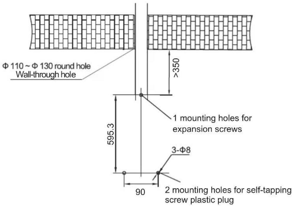
• Type of Installation (B22)
- Installation of compulsory gas supply and exhaust pipe of the unit: a. Installation mode of topside exhaust.

Adapter installation instruction:

- Remove the old pipe and see the outlet of the fan.
- Insert the adapter down the fan outlet into the upper part of the fan.
Adapter overall dimension and interface dimension:

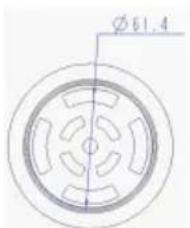
As show in the figure below, tap in expansion screws for fixation, hang the unit vertically and screw it down with nuts, insert plastic plugs below it and screw down self-tapping screws.
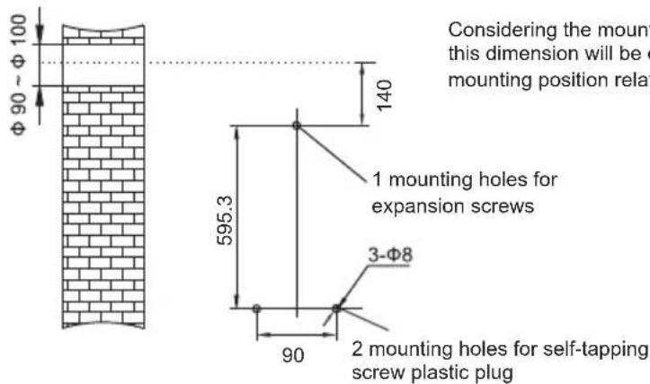
b. Installation mode of top rear exhaust.

As show in the figure below, tap in expansion screws for fixation, hang the unit vertically and screw it down with nuts, insert plastic plugs below it and screw down self-tapping screws.

SVCG11EB

NOTE
The B22 gas water heater must be installed and used in well ventilated area, out-side a bathroom.
• Installation of gas pipe
a. Caution
① Be sure to select a special gas rubber hose or a suitable rigid tube and a gas relief valve.
② Select the pipe size according to Table 1.
③ The length of the rubber hose shall not exceed 2 meters.
④ The rubber hose must be connected to the red line position of the gas inlet joint and secured with a clamp.
⑤ After installation, check the unit with suds for gas leak.
b. Connect the unit to the gas joint with G1/2 pipe thread.
When LPG is used, connect the attached gas inlet hose joint to the gas supply pipe joint of the unit (be sure to mount a rubber sealing ring), then connect it with an 9.5mm special gas rubber hose. Insert one end into the hose joint of the unit's gas inlet until the hose is fitted over the red groove of the joint, and hold it with a clip.

• Installation of water inlet and outlet pipes.
Connect the water inlet and outlet pipes and tap water pipe of the unit with an 10mm metal hose, or with a water pipe with an inner diameter of greater than 15mm.
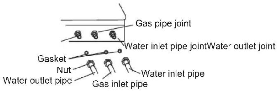

NOTE
Add a rubber sealing gasket when a metal hose is used.
3.4 Installation Caution
- Since this machine adopts compulsory air inlet and exhaust, it is permissible to be installed in the bathroom, however, the exit of exhaust system must be extended outdoors, and the distance between the end of outdoor exhaust pipe and adjacent or other articles must be larger than 600mm.
- This machine is not allowed to be installed outdoors to prevent damage of the heater caused by freezing of water.
- A water inlet valve shall be installed at the water inlet pipe of the unit, so that the water supply can be switched off in repair.
- The mounting position of the unit is made of a nonflammable material. If it is made of an inflammable or flame resistant material, a heatproof plate shall be used for heat insulation, whose distance from the wall shall be greater than 10mm.
- The lower edge of the unit shall be about 1.5m above the ground, so that its combustion can be easily observed and its temperature adjusted.
- A LPG user shall select a suitable, high-quality gas relief valve, whose specification shall not be less than 1.5m3/h to guarantee the gas pressure and flow input into the unit.
- Natural gas users shall use a hard metal pipe with the same diameter as the gas inlet of the unit to reduce gas closure and pressure loss.
- There should be no inflammable or explosive material around the unit and the fume exhaust port, e.g., kerosene, gasoline, alcohol, paints, paper, clothes, etc.

- Do not point the exhaust port directly to a nearby window when install the unit.
- The unit shall not be installed where there is corrosive gas or article, and there should be no exposed wire, electric appliance or gas pipe above it, or any gas range or baking oven below it.
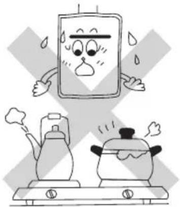
- Receptacle shall be installed on the left or right side of the unit and must be grounded reliably.
4. METHODS OF USING
4.1 Preparation Before Ignition
- Insert the power supply plug and switch on the power.
- Open the main gas valve switch.
- Open the water inlet valve before ignition.


NOTE
Hot water outlet with control panel or line controller. The line controller is optional for custom-ers. If without special request from customers, the unit will be equipped with no line controller.
• Finish above mentioned preparation and confirmation before use.
- Press ON/OFF key on the operation panel, the LED will display the default water outlet temperature of 4°C, press the ▲/▽ key to set the hot water outlet temperature.

4.2 Ignition And Operation
- Ignition: Open the water outlet valve. the unit will start the exhaust device automatically and make a "frizzle" ignition sound; the LED will display the actual water outlet temperature. When the unit is running, there will be air in the gas pipe; therefore a single ignition might not work sometimes. In this case, close the hot water valve immediately and restart the unit after 10-20 seconds.

NOTE
For the first use or when the unit has not been used for a long time, operate as above repeatedly unit all the air in the exhaust pipe has been discharged.
- Adjustment of water outlet temperature: The preset range of the water outlet temperature is 35\~65 °C. Every time the Temp Up key is pressed, the set temperature will rise by 1 °C, every time the Temp Down key has been released for 2 seconds, the screen will display the measured water outlet temperature.
- The set water outlet temperature has the memory function. However, in case of power off, the memory function will be disabled.
- Sound prompt function: In normal circumstances, every time the key on the operation panel is pressed, the key on the operation panel is pressed, the buzzer will make a sound for 0.5 second. When the unit fails or the 20-minute timing protection ends, the buzzer will give out continuous alarm sounds, the combustion indicator will flash rapidly and continuously, Press the ON/OFF key, the alarm will disappear and the screen will be closed, but the power indicator will not go out (green).
- Use of multiple line controllers: The priority principle will apply to the use of multiple line controllers, whichever is stated first will have the priority, while the power indicator of the controller with priority will flash, the remaining controller with priority will flash, the remaining controllers can be displayed but will not operate; the display will be that of the one with priority. When the controller with priority shuts down, the display of the remaining controllers will be closed.
To use hot water again after stop, do not let the hot water splash you, because the water temperature in the unit might be very high. Use it after several seconds of hot water outflow to avoid scald.

4.3 Stop To Use
① Close the water outlet valve, the unit will stop automatically.
② Press the ON/OFF key on the operation panel.
③ Close the water inlet valve.
④ Close the main gas switch.
⑤ Switch off the power switch or pull out the power supply plug.
4.4 Anti-frozen Treatment Of The Unit
• Ani-frozen water supply method:
Not only the main body, but also the cold/hot water pipes and valves can be protected from freezing. When there is a line controller, the ON/OFF key of the line controller shall be at the OFF position before you proceed with the following operations.
① Close the gas valve.
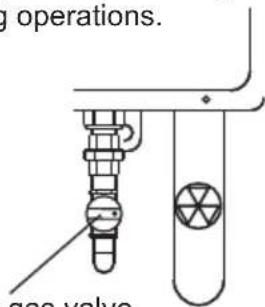
Close the gas valve.
② Open the water outlet valve (the water inlet valve is semi-open).

Since the flow is unstable, please confirm the flow again 30 minutes later. In cold weathers, be sure to increase the water flow.
• Ani-frozen drainage method:
When there is a line controller, the ON/OFF key of the line controller shall be at the OFF position and the unit shall be operated as follows:
① Close the gas valve.
② Pull out the power supply plug to cut off the power.
③ Close the water inlet valves.
④ Open all water outlet valves.
⑤ Remove the drain valve and the filter net faucet.
⑥ After drainage, replace the drain valve and the filter net faucet.

Maintain the above condition until the next operation after drainage.
① Open the water inlet valve, stop the water outlet when there is water outflow from the water outlet.
② Restart the unit in the order described in page 14(Preparation Before Ignition)

NOTE
In case of reuse, if you don't operate as above, there might be an error.
• Cautions for anti-frozen of the unit
① Neither the electric heating antifreeze method nor the antifreeze drainage method can prevent freezing of the pipes and valves. All pipelines and valves from the cold water inlet to the hot water outlet shall be wrapped with heat insulation materials to prevent freezing.
② When freezing has occurred, be sure to thaw it. Make sure there is no water leakage and the unit is running properly before use.

WARNING
All adverse consequences of wall and floor damage arising from water leakage due to failure to take any antifreeze measure will be born solely by the user.
Take the electrical plug out before clean or maintenance.
- Check up frequently to see whether the gas supply pipelines (rubber hose) are in good conditions without aging, cracks. Pay attention to periodic replacement of rubber hoses. In order to prevent gas leakage, check the joints of pipelines frequently by using suds to see if there are bubbles given off.
- A water heater must be examined, cleaned after it has been used for a period of time (generally about half a year) to guarantee normal operation of the heater. Observe the flame frequently. When the flame turns to be yellow from blue, accompanied by black fume, the heater must be cleaned.
- Clean the casing of the unit with water and neutral cleaner other than any chemical cleaner or volatile solvent, otherwise the casing will fade and lose luster.
- Clean the filter net at the water inlet of the unit regularly.
- Wipe the casing of the unit with soft and clean cloth often.

- The water heaters must be examined, cleaned periodically by the professional personnel.
- Non-professional personnel can not open the cases of water heaters. Pull out the power plug when opening the case of a water heater. Do not wet the power socket with water in use to ensure safety.
6. TROUBLESHOOTING

WARNING
When there are any abnormal phenomena found, such as gas leakage, abnormal burning (backfire, deflaming, yellow flame or black fume, etc.), abnormal odors or sounds, etc., or other emergencies happened, close the gas valve immediately, and contact with the maintenance department or the gas company for disposal.
- Advanced error code display for more convenient operation and maintenance. Error codes:
| Error codes | Description Treatment | |
| E5 | Fan failure | Contact Midea for after-sales treatment. The system need to reset by manual to eliminate error codes. |
| E0 | Outlet temperature sensor error | Check whether the outlet water temperature sensor is damaged. If so, replace the part and system can recover by itself. |
| F3 | Water flow over the maximum value | When water flow less than 22L/min, system can recover by itself. |
| C4 | Exhaust Blockage | Check whether the exhaust pipe is blocked. Clean up the blockage at the air inlet and exhaust outlet of the pipe. And then system should be reset by manual to eliminate error codes. |
| C2 | Air Pressure Sensor Wrong Connection | Check whether the connection of the air pressure sensor is normal. System can recover by itself after normal connection. |
| C3 | APS doesn't have pressure | Contact after-sales personnel to check whether the air pressure sensor is normal. System can recover by manual to eliminate error codes. |
| E4 | Over-temperature protection | System can recover by manual to eliminate error codes. |
| F2 | Inlet temperature sensor defective | Check whether the inlet water temperature sensor is damaged. If so, replace the part and system can recover by itself. |
| E3 | Thermostat error | System can recover by manual to eliminate error codes. |
| C0 | Ignition failure | Check whether there is gas in the gas pipe, or contact the after-sales department to check whether the ignition needle is damaged .The system need to reset by manual to eliminate error codes. |
| E6 | Gas valve connection error | Contact the after-sales service personnel to check whether the connecting wire of the valve is wrongly connected. The system need to reset by manual to eliminate error codes. |
| E2 | Wrong flame signal | Contact after-sales personnel to check whether the flame feedback needle is normal. The system needs to reset by manual to eliminate error codes. |
| C1 | Gas valve leakage | Contact the after-sales service personnel to check the valve for leakage. The system needs to reset by manual to eliminate error codes. |
| E1 | No flame signal | Contact after-sales personnel to check whether the flame feedback needle is normal. The system needs to reset by manual to eliminate error codes. |
Manual reset steps: Closing the water inlet or pressing ON/OFF button can eliminate the fault.
• Common failures and treatment.
| PhenomenaCauses | Flameout during operation. | The unit will not ignite after starting | Deflagration. | Yellow flame accompanied by black fume. | Abnormal flame accompanied by abnormal odors | Abnormal sounds during ignition. | The water is still not hot even at the position of high temperature. | The water is too hot at the position of low temperature. | The flame goes out when the unit is set to the "Winter" position | The fire does not die out after the heater is turned off. | Treatment | |
| The gas valve is not opened. | ● | Fully open the gas valve or replace with a new gas vessel. | ||||||||||
| The gas valve is half opened. | ● | Fully open the gas valve. | ||||||||||
| There is air filled in the gas pipes. | ● | Open and close the water outlet valve continuously for several times till the ignition successes. | ||||||||||
| Inappropriate gas pressure | High | ● | ● | ● | ● | Ask the maintenance personnel to check the gas pressure regulation valve. | ||||||
| Low | ● | ● | ||||||||||
| Freeze | ● | Contact with the maintenance personnel. | ||||||||||
| Inadequate hydraulic pressure of inlet | ● | ● | ● | ● | Ask the maintenance personnel to check hydraulic pressure. | |||||||
| The burner is blocked. | ● | ● | ● | Contact with the maintenance personnel. | ||||||||
| The heat exchanger is blocked. | ● | ● | ● | Contact with the maintenance personnel. | ||||||||
| Failures of water flow sensor | ● | ● | Contact with the maintenance personnel. | |||||||||
| Failures of pulse igniter | ● | ● | Contact with the maintenance personnel. | |||||||||
| Drop-off of internal wires | ● | ● | Contact with the maintenance personnel to connect the loosed or dropped wires correctly. | |||||||||
| Failures of fan | ● | ● | Contact with the maintenance personnel. | |||||||||
| Failures of electromagnetic valve | ● | ● | ● | Contact with the maintenance personnel. | ||||||||
| Failures of feedback electrode | ● | Contact with the maintenance personnel. | ||||||||||
| Abnormal discharge distance or discharge position | ● | Adjust the ignition pin, and contact with the maintenance personnel. | ||||||||||
| The power is switched off, power failure | ● | ● | Switch on the power. | |||||||||
| The master cold water valve is not opened. | ● | Fully open the master water inlet valve. | ||||||||||
| Incorrect adjustment method of water temperature | ● | ● | Refer to the adjustment procedure for winter-summer fresh air. | |||||||||
| Inadequate supply of fresh air | ● | ● | ● | Improve the ventilation immediately to guarantee adequate fresh air supply. | ||||||||
| Blocked fume duct | ● | ● | Reuse after clearing away foreign objects from the flue. | |||||||||
If other failures are encountered, stop use of the water heater immediately, and notify the professional maintenance department for repair. The users shall not remove or repair the water heaters without prior permission, otherwise an accident might occur.
No use of water heaters with any failures.
DISPOSAL OF PACKAGING AND

Dispose of packaging in an environmentally-friendly manner. This appliance is labelled in accordance with European Directive 2012/19/EU concerning used electrical and electronic appliances (waste electrical and electronic equipment - WEEE). The guideline determines the frame work for the return and recycling of used appliances as applicable throughout to the EU. PACKAGE INFORMATION: Packaging materials of the product are manufactured from recyclable materials in accordance with our National Environment Regulations. Do not dispose of the packaging materials together with the domestic or other wastes. Take them to the packaging material collection points designated by the local authorities.
The product is subject to change without notice. Please keep this manual properly.
Modelo: SCE1100ADB
SCE1300ADB
LISTA DE CONTEÚDOS
TÍTULO
PÁGINA
4.3 Parar de o utilizar


- ÍNDICE DE CONTENIDOS
- TÍTULO
- PÁGINA
- MÉTODOS DE USO
- 4.3 DEJE DE USARLO
- DOMESTIC INSTANTANEOUS GAS WATER HEATER
- TABLE OF CONTENTS
- TITLE PAGE
- CAUTIONS
- 1.1 SPECIAL CAUTIONS
- WARNING
- 1.2 PREVENTION OF GAS ACCIDENT
- 1.3 GUARDS AGAINST FIRE
- 1.4 OTHER CAUTIONS
- PRODUCT INTRODUCTION
- 2.3 FUNCTIONAL FEATURES
- 2.4 INTERNAL WIRE DIAGRAM
- UNIT INSTALLATION
- 3.3 INSTALLATION MODES
- 3.2 BRIEF INTRODUCTION
- 3.3 PACKING LIST PARAMETERS
- NOTE
- 3.4 INSTALLATION CAUTION
- METHODS OF USING
- 4.1 PREPARATION BEFORE IGNITION
- 4.2 IGNITION AND OPERATION
- 4.3 STOP TO USE
- 4.4 ANTI-FROZEN TREATMENT OF THE UNIT
- TAKE THE ELECTRICAL PLUG OUT BEFORE CLEAN OR MAINTENANCE
- TROUBLESHOOTING
- DISPOSAL OF PACKAGING AND
- LISTA DE CONTEÚDOS
- 4.3 PARAR DE O UTILIZAR
Brand : SVAN
Model : SCE1100ADB
Category : Heating