ELOP+ - Uncategorized Manley - Free user manual and instructions
Find the device manual for free ELOP+ Manley in PDF.

| Product Type | Stereo Electro-Optical Vacuum Tube Limiter / Compressor |
| Dimensions (W x D x H) | 19" x 7" x 3.5" (occupies 2U) |
| Unit Weight | 9.5 lb (4.3 kg) |
| Shipping Weight | 10 lb (4.5 kg) |
| Power Requirements | 90–254 VAC, 50/60 Hz, 26W |
| Vacuum Tubes per Channel | 1 x 5751 (gain), 1 x 6922 (output) |
| Compression Ratio | 3:1 (Compress mode) |
| Limiting Ratio | 10:1 (Limit mode) |
| Attack Time (Limiter) | 15 ms |
| Release Time (Limiter) | 200 ms |
| Attack Time (Compressor) | 75 ms |
| Release Time (Compressor) | 200 ms |
| Side‑Chain High‑Pass Filter | 80 Hz (jumper selectable to 150 Hz) |
| Input Impedance | 14 kΩ |
| Output Impedance | 150 Ω (impedance balanced) |
| Maximum Input Level | +18 dBu (0.01% THD) |
| Maximum Output Level (100 kΩ load) | +30 dBu (0.009% THD+N) |
| Frequency Response | –0.15 dB @ 10 Hz, –0.1 dB @ 20 kHz |
| Dynamic Range | 118 dB |
| Signal‑to‑Noise Ratio | 92 dB (ref. +4 dBu) |
| Tube Lifespan (typical) | 5000–6000 hours; replace as needed |
| Safety Features | Mute during 30‑second warm‑up; high voltage warning; protection circuitry |
| Maintenance | Clean with damp cloth; alcohol for stubborn marks; do not attempt internal service without qualified technician |
| Country of Manufacture | USA (Handcrafted in Chino, CA) |
Frequently Asked Questions - ELOP+ Manley
User questions about ELOP+ Manley
0 question about this device. Answer the ones you know or ask your own.
Ask a new question about this device
Download the instructions for your Uncategorized in PDF format for free! Find your manual ELOP+ - Manley and take your electronic device back in hand. On this page are published all the documents necessary for the use of your device. ELOP+ by Manley.
USER MANUAL ELOP+ Manley
ELOP ^® +
ELECTRO-OPTIONAL ACCOUNT TELEFERENCE PRESSORSSOR
OWNER'S MANUAL
CHAPTER
PAGE
i) Introduction 1
ii) Manual Conventions 1
iii) Copyright Notice 1
- Important Safety Instructions 2
- Getting Started 2
- Front Panel 3-4
- Rear Panel 5
- Operational Notes 6-7
- Advanced Tricks 8
- Questions & Troubleshooting 9
- Servicing 10-11
- Specifications 12
- Recall Sheet 13
This equipment has been tested and found to comply with the limits for a class B digital device, pursuant to part 15 of the FCC Rules. These limits are designed to provide reasonable protection against harmful interference in a residential installation. This equipment generates, uses and can radiate radio frequency energy and if not installed and used in accordance with the instructions, may cause harmful interference to radio communications. However, there is no guarantee that interference will not occur in a particular installation. If this equipment does cause harmful interference to radio or television reception, which can be determined by turning the equipment off and on, the user is encouraged to try to correct the interference by one or more of the following measures:
* Reorient or relocate the receiving antenna.
* Increase the separation between the equipment and receiver.
* Connect the equipment into an outlet on a circuit different from that to which the receiver is connected.
* Consult the dealer or an experienced radio/TV technician for help.
i) An Introduction To The Manley ELOP ^® + Limiter & Compressor
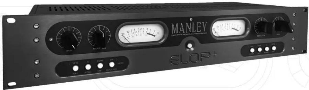
Thank you for selecting the Manley ELOP®+ Electro-Optical, Stereo Vacuum Tube, Limiter & Compressor. This professional unit has been designed by Manley Laboratories to perform under the most demanding situations. The ELOP®+ replaces our legacy unit the ELOP® which was originally introduced in 1991.
Due to its inherently quick attack, the ELOP+ is a skilled soldier for tracking vocals or individual instruments. The useful side-chain high-pass filter and 3:7 Compressor makes this piece of equipment a versatile and useful tool in the studio. Each ELOP+ features our hand wound MANLEY IRON® transformers and large easy to read amber back lit VU Meters, which can monitor the Output Level or Gain Reduction.
Since the early 1990's, the Manley ELOP has been a tracking hero, effortlessly controlling dynamics on countless records around the globe, delivering the coveted classic, all-tube sound that Manley Labs is known for. We revisited our vintage 1990's ELOP units and modeled the tonality of the original.
Thank you for choosing our MANLEY ELOP+. Enjoy!
ii) Manual Conventions
Please take a few moments to read through this manual carefully. It contains essential information for the proper operation of your Manley ELOP+ Limiter & Compressor.
Also in the following pages you will find useful hints and tips, allowing us to help you achieve the utmost performance from your equipment.
Below are the following conventions, used to pick out particularly important parts of the manual. The symbols are found in the margin next to the body of text of interest.

Especially Useful Tip

Important Information. Read Carefully

Caution! Pay Attention!

Refer to another section in this Manual
iii) Notice
This manual provides general and technical information for use, installation, and operating instructions for the MANLEY ELOP+ Limiter & Compressor. Manley Laboratories, Inc. reserves the right to make changes in specifications and other information contained in this publication without prior notice. Manley Laboratories, Inc. shall not be liable for errors contained herein or direct, indirect, incidental or consequential damages in connection with the furnishing, performance, or use of this material. No statement contained in this publication, including statements regarding suitability or performance of products shall be considered a warranty by Manley Laboratories, Inc. for any purpose or give rise to any liability of Manley Laboratories, Inc.
© 2015 COPYRIGHT Manley Laboratories, Inc. All rights reserved.
This manual and any associated artwork, product designs, and design concepts are subject to copyright protection. No part of this document may be produced, in any form, without prior written permission of Manley Laboratories, Inc. ELOP+, MANLEY ^® and the Manley Laboratories, Inc. logo are trademarks of Manley Laboratories, Inc.
1. Important Safety Instructions
- Water and Moisture - Do not use The ELOP+ near any source of water or in excessively moist environments.
- Object and Liquid Entry - Care should be taken so that objects do not fall, and liquids are not spilled, into the enclosure through the openings.
- Heat & Ventilation - When installing The ELOP+ in a rack or any other location, be sure there is adequate ventilation. Improper ventilation will cause overheating, and can damage the unit. The unit should be situated away from heat sources, or other equipment that produce heat.
- Power Sources - The ELOP+ has an internal universal power supply which can operate in any country. It has an input voltage range of 90-260 VAC at 50/60 Hz.
- Cleaning - The EaO be cleaned with just a damp cloth, or alcohol/methylated spirits for more stubborn marks.
- Damage - If after unpacking your dealer.
- Servicing - Do not attempt any servicing without consulting your dealer or Manley Laboratories, Inc. The user should not attempt to service the unit beyond that described in the operating instructions. All other servicing should be referred to qualified service personnel. This unit has high voltages present, even after the power has been switched off.
- DO NOT connect the AC supply cord until all other connections have been made. Afer initial power up the power LED will "blink" for thirty seconds. The unit remains in MUTE until this warm up period has elapsed.
2. Getting Started
Unpacking your MANLEY ELOP+:
The ELOP+ is secured in its packing carton by two Duracell foam end-caps.
Hold the unit by the middle and simply lift the unit vertically straight out of the box.
After it has been unpacked, check that nothing is loose inside when handling the unit. The unit is shipped with the vacuum tubes installed. Make sure they are not loose by looking through the vent holes on the top cover. Ensure they are standing upright in their sockets.
It is advisable to keep the original packaging. In the event of servicing or relocating, the original packaging ensures that the unit will always be shipped safely.
This package contains the following;
1 x Manley ELOP+ Stereo Limiter Compressor
1 x Manley ELOP+ Owner's Manual
1 x IEC Power Cable
1 x Warranty Registration Card
1 x Warranty Statement


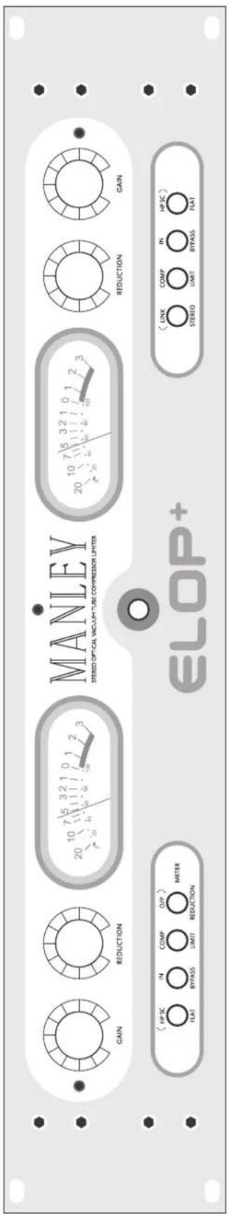
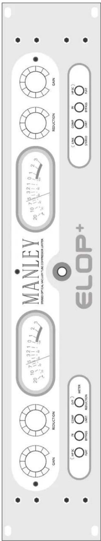
3. Front Panel
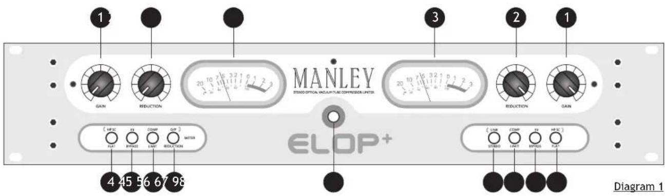
1 GAIN CONTROL
The GAIN control is available on both the left and the right channel. It adjusts the input drive of that audio channel. Unity gain is about the seventh marking, or 1 o'clock. (This is not an absolute, the user should adjust the gain controls when the Limiter is active, by reading the level on each meter.) Limiting usually requires some additional "make-up" gain to compare IN / BYPASS.
2
REDUCTION CONTROL
Each channel has a REDUCTION control. REDUCTION adjusts the amount of limiting or compression in that channel. This could also be called "threshold". Turning this control clockwise increases the amount of limiting or compression.
3
VU METER
There is a VU Meter for each channel in the ELOP+. It shows the amount of gain reduction in dB from the 0 dB mark, when the switch ⑦ is not selected, set to REDUCTION. When the switch labeled ⑦, is selected to O/P and illuminated, the meter measures the output level in decibels.
Note: VU meters and PEAK meters rarely agree, digital recorders usually use peak meters - Rely on those for a clean recording. VU meters are standard with analog tape machines and big consoles because they correspond well with perceived loudness.
4
HP SC CONTROL
The High Pass Side Chain filter is factory set to 80Hz. When this switch is engaged and illuminated, everything above 80Hz will drive the limiting or compression action. This is useful if you want the bass to come through with full impact and limit or compress everything else. Also if you don't want the kick drum or bass line driving the whole compressor action, engage this switch. This filter frequency may be set to a slightly higher frequency of 150Hz by changing the internal HPSC filter select jumper W1 & W2 for each channel, located on the front panel PCB. (Consult Chapter 8, Servicing and refer to diagram 3)
5
IN / BYPASS CONTROL
This switch will disengage the active dynamic control section of the unit. If the switch is engaged and illuminated to the "IN" position the audio will pass through either the whole unit and all the front panel controls will function. When this switch is set to "BYPASS" the audio still flows through the tubes in the unit, but at Unity Gain. Use this switch to compare the processed sound with the original.
6 COMPRESS / LIMIT CONTROL
This switch allows the ELOP+ to use two different compression ratios, offering either compression at approximately 3:1 when the switch is engaged and illuminated or limiting at approximately a 10:1 ratio.
3. Front Panel
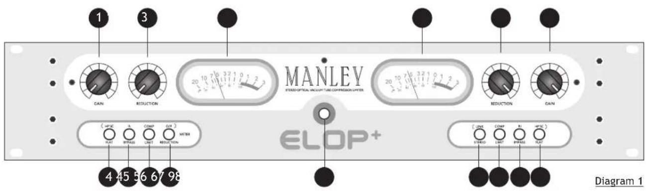
7 METER SELECT
The Meter select switch allows the user to monitor either Gain Reduction or the Output level of the unit. When the switch is engaged and illuminated, the output of the particular channel you are monitoring is visible in the corresponding VU Meter.
8 POWER SWITCH
The Power Switch glows a soft amber color when an IEC power lead is connected to the unit. This indicates that the unit is connected to the AC main supply and the ELOP+ is in STANDBY mode. Engaging the power switch takes the ELOP+ out of standby mode and into warm-up mode. The power switch will illuminate to a brighter amber and the backlit VU meters will start to flash. This warm-up process last 30 seconds after which the MUTE relays will lift and the VU meters will stop flashing.
9 LINK / STEREO FUNCTION

When the LINK function switch is engaged and illuminated the ELOP+ applies the same amount of gain reduction to both the left and right channels. This is done to prevent image shifting that can occur if each channel is compressed individually. It becomes noticeable when a loud element that is panned to either edge of the stereo field raises the level of the program to the compressor's threshold, causing its image to shift toward the center of the stereo field.
We suggest that when in LINK mode both channels have their controls set the same. It requires the user to use both sides, so that the limiters react equally based on whichever side has the loudest peak.
When in LINK mode there is no "Left Channel Master". Each control still works independently of each other. STEREO is used on stereo tracks so if either channel is called to limit. This prevents image shifts and an instrument should stay where you panned them.
You should generally stay in STEREO mode if using the unit to limit or compress two different mono tracks, such as vocal in one channel and guitar in the other.

Note that when in LINK mode, the mode of operation for the ELOP+ for either a LIMITER or COMPRESSOR must be set the same for both channels. Switch (6), Diagram 1. If one channel is set to LIMIT and the other set to COMPRESS this will stop the unit functioning correctly in LINK mode.
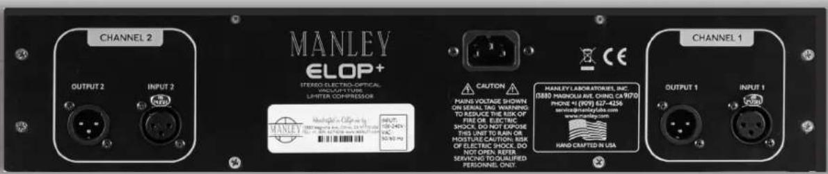
- Rear Panel
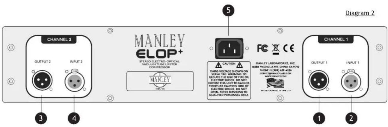
1 XLR OUTPUT (IMPEDANCE BALANCED) (CH1, LEFT) PIN 1: GROUND
PIN 2: (+)
PIN 3: (-)
2 XLR INPUT (TRANSFORMER BALANCED) (CH1, LEFT) PIN 1: GROUND
PIN 2: (+)
PIN 3: (-)
3 XLR OUTPUT (IMPEDANCE BALANCED) (CH2, RIGHT) PIN 1: GROUND
PIN 2: (+)
PIN 3: (-)
4 XLR INPUT (TRANSFORMER BALANCED) (CH2, RIGHT) PIN 1: GROUND
PIN 2: (+)
PIN 3: (-)
5 IEC MAINS CONNECTOR Standard IEC mains connector for 50 /60 Hz AC.
(INPUT MAINS VOLTAGE 90 VAC - 254 VAC)
7. Operational Notes
The Manley ELOP+ follows certain traits and traditions established by the UREI LA-2A and similar historic leveling amplifiers.
These traits can be divided into two aspects - electronic and operation.
The electronic concept is simple and rather clean, use the audio to light up LEDs or lamps which shine onto photo-resistors. These photo-resistors, in combination with a fixed resistor, simply act as a voltage divider to attenuate the signal. The tube line amplifier functions to provide extra gain to make up for attenuation losses and then acts as a fine cable driver. Simple, elegant, and minimal.
Operation of this type of design is also simple, elegant, and minimal. There are usually only “threshold” and “gain” controls. Most have no user adjustment of “attack”, “release”, “ratio” or functions for de-essing or external side chains. To put it one way, the user is “stuck” with fixed time constants and a feature list that seems utterly anemic compared to dynamic processors costing far less...
...so why are “LA” style opto-based limiters so popular? Several reasons.
To paraphrase Letterman, “The number one reason why “LA” style limiters are favorites is because.... They work right on vocals.” This “rightness” has a few aspects. The first is that “LA” style limiters don’t leave much trace of limiting as they work. This is partly due to the clean tube stages, the simplicity of the opto circuit and partly because the user can’t alter the attack and release.
Almost every VCA based design seems to leave electronic personality on that critical vocal track. This is usually undesirable. Our ELOP+ circuit has no active limiting in the signal path. Tube circuits have the potential to be musically more transparent than transistors because tubes are generally more linear devices and work with high voltages offering very high headroom.
However, there are many poor examples of tube circuits in the field, and many ways to butcher the quality. We chose to use our favorite simple tube line amplifier circuit which we also use in our Mic Preamps, Enhanced Pultec Equalizers and the CORE.
Back to this matter with fixed time constants. We get requests to modify our ELOP+ for more controls, but we get even more people raving about how great and useful the ELOP+ is now. The natural attack, release, knee, and ratio (curve) are a natural result of the LDR & LED Cell we chose to use. The choice was based on the inherent attack and release characteristics of this LDR & LED Cell and is loved around the world for decades.
There is a major advantage of having fewer controls and a reason for choosing this type limiter. You simply adjust the Threshold for the desired limiting amount and adjust the Gain for the desired level to the recorder - then hit record! The limiter does what its supposed to do - nothing more, nothing less. Kinda like automatically right, strangely quick and easy, and pretty much non-distracting.
We use the phrase “Set it and forget it”. This is a very important feature that would be lost with a variety of controls. A good engineer wants to be ready to record “now” and does not want to be fussing with controls while a lead vocal is going to tape. Unfortunately most compressors drag the engineer’s attention away (and often the singer’s and producer’s attention away as well).
The time and slope characteristics of optical elements are not easy to describe and probably even more difficult to simulate. The attack is fast; not super-fast “brick wall”, but fast enough to “catch” consonants. It is also a function of level. At lower reduction levels and lower peaks the LDR & LED Cell is slower. It becomes faster with sharp peaks and heavier levels of reduction. Release is similar but 10 to 20 times slower. Quick peaks are handled with quick release and as gain reduction nears zero the LDR & LED Cell gets slower like gentle braking to a stop.
7. Operational Notes
The slope or ratio is also difficult to simulate. The initial ratio is low and becomes higher with more gain reduction until the LEDs light up fully and further reduction is not possible.
This upper limit of reduction is in the area of 20 dB or at the bottom of the GR meter where the ratio becomes low again, but this would be a severe setting that few engineers could use. Distortion becomes audible at very deep limiting.
In a tech shop, it is easy to drive the limiter to 20 dB of reduction and beyond where the GR meter shows a flaw in that it “folds back”. We put a higher priority on having the meter show what the unit was doing accurately with “normal settings” than extreme test bench observations. Test benches don’t make hit records.
So these types of electro-optical limiters seem to be great for vocals, but what else are they used for? And what about sounds where the time constants are less than optimum?
Historically, “LA” style limiters were often used for bass and guitar tracks. They can be ideal for brass, saxes, synths, and similar sounds with superb results. There are other compressors that work well for these instruments, but few that are as transparent. Usually, when you hear of an engineer using another type of compressor for these instruments, it is framed with “for the crunch” or because they add some desired color. There are only a very small number of “clean” general purpose variable time compressors which seem to give “LA” style units competition - our Variable Mu® is at the top of that list.
Where the “LA” style limiters are not always appropriate is for percussion and for mixes where the percussion is just right. The cell typically reacts fast to peaks - fast enough to remove drums from a mix but not quite fast enough to be called “brick wall”. Individual drums tend to have a little of the initial transient let through, but the desirable tone
of the drum is diminished. If used gently, this can be applied to brighten up the attack of the drum, but it is difficult to apply in practice because drums can be very dynamic.
One great use is on the room mics. The initial drum sound is pulled down, then the natural reverb is increased. Shades of early Led Zep. While we mentioned that “LA” style limiters are not what we suggest for mixes, there are times when the drums are too loud or when the engineer can mix “into” the limiter. Both techniques are possible, but not necessarily easy. One trick is to just barely tickle the GR meter. Some of our clients use the ELOP+ on mixes as an effect. This application is valid as long as the effect given and the effect desired are the same.
There are not many options for adjustment and fine tuning. The good news is that the ELOP+ is clean enough to pass a good mix. In a live sound setting the ELOP+ will perform as a fine speaker protection device. Once again the Threshold is set for minimal limiting with music and is just adjusted to encourage the pyrotechnician to try harder tomorrow to kill a few woofers.
6. Advanced Tricks
Here are a few tricks that are not really for rookies. They come from guys doing major records for years and won't work unless you've mastered the basics. In other words if we gave you a Strat and Marshall it won't make you another Jimi. Also we don't suggest that you try these out while paying big-time studio rates - they may not be easy to get right at first.
Trick#1
Each compressor or device in the chain has certain flavors and characteristics and with experience we grab the ones we like because of the sound - not because “it is a compressor”. The idea is to use several cool compressors in a chain getting flavors from each depending on how much GR (gain reduction) is used in each and how hard they are driven. It’s this second concept that can be tricky.
How far to turn up each Make-up Gain to overdrive or not overdrive the next unit - and still not get flooded with noise when the music stops. You can chain the two channels of the ELOP+ and turn up the make-up of the first channel. This works best with classic discrete and tube units that have inherently high headroom. You would usually not try this with IC-based or 500 series units.
The finesse comes from which order they are patched. See how long it might take to get best results.
Trick#2
This one is easier, but also requires serious listening. Rather than just “inserting” a limiter, try driving the limiter from the tape patch (pre EQ), returning it to a spare fader and mixing it with the original.
So what is so tricky? How you EQ and automate and add effects to these channels. You can also have fun phase reversing one of the channels. You get cancellation but only at a certain level. It is sort of like gating, but different - it is a way of controlling the “ambiance”.
Trick#3
Using one track to “duck” another. This may work better with compressors with attack and release and ratio controls if you are thinking drums. Bass and vocal is very cool with the ELOP+. Set it up like trick#2 with bass in one channel and vocal in the other (in LINK mode) and experiment with each threshold.
Two guitar tracks also work here sometimes.
Obviously, we pull out this trick when two tracks are stepping on each other and EQ isn't making enough
room for clarity.
Trick#4
Drive the compressor from an AUX send and return it to a channel. Once you have some limiting, carefully turn up that aux send on the return channel to “feed back” into the limiter. Watch out for real howling feedback and over the top limiting. If you are lucky it won’t scream during the quiet parts.
The key is balancing the faders, track auxes, the return auxes, the thresholds, and make-up gains. The technique can get pretty crunchy and wild. Works best with not-so-clean compressors, but is interesting with the ELOP+.
Trick#5
This one is a way to get a very good single channel De-esser from the ELOP+ or other compressor good enough for lead vocals. Split the Insert send of the vocal to the ELOP+ and to a spare channel. EQ the snot out of that second channel boosting the 5 or 6 kHz band and chopping everything below that.
Use the insert from this channel to drive the other channel of the ELOP+, but it is unlikely that you want this fader up. Set the ELOP+ to Link. The threshold of the first channel sets compression and the second channel sets de-essing.
Unlike some de-essers it will not chop highs, but reduce wide-band which is less obvious. The only drag is that the release is a little slow. Remember good de-essing is not to remove esses - the idea is to reduce esses and make them natural sounding.
BTW if you need to de-ess, you might want to re-think your choice of gear. There are 3 main reasons we get horrible esses:
1) a gap in the singer's teeth or just a strange voice,
2) too much or wrongly chosen EQ, or,
3) gear that distorts the highs.
If the cause is “1”, try sticking some dental wax in the gap. No joke! If the cause is “2” then we can tell you some EQs allow one to boost highs with less problems with the esses or you might try boosting a higher freq, or less during tracking. If it is “3” you may want a better mic or sell off some of that cheap IC gear that seems to be distorting the top in a way that you don’t like.
Actually we have heard some pretty expensive gear - both tube and solid state - that has this particularly ugly distortion. If in doubt, try some tough percussion through it like shakers or tambourines, and see how they sound...
7. Questions & Troubleshooting
Q: No Power, No Indicators?
Ensure the IEC plug at the rear of the unit is inserted all the way. Wait at least five minutes before trying the power switch again. If the unit does not power up then check the fuse on the PSU. (See Servicing, Diagram 3)
Q: The Unit Is Switched On, No Sound?
First try plugging the IN and OUT cables into some other piece of gear to verify that your cables are OK. Next check the front panel, try BYPASS. If you have sound now it might be a good idea to turn up the output levels to about 1 o'clock (rather than fully counterclockwise which is “minus infinity”.
Q: Levels Seem To Be Wrong, No Bottom?
Several possible scenarios. Manley uses the professional standard of +4 dBm = Zero VU = 1.23 volts AC RMS. A lot of semi-pro gear uses the hi-fi reference of -10 dBm = Zero VU. This is a 14 dB difference that will certainly look odd and may tend to distort. Often there are switches on semi-pro gear to choose the pro reference level. We do not provide that kind of switch because of inevitable compromises in the signal path. If the loss looks close to 6 dB and it sounds thin then one half of the signal is lost. The cause is probably wiring again. One of the two signal carrying wires (the third is ground / shield on pin 1) is not happening. Check the cables carefully because occasionally a cable gets modified to work with a certain unit and it seems to work but its wrong in other situations. If only one side of the ELOP+ exhibits this problem, it may be a problem in the unit itself.
Q: Only One Channel Is Functioning?
This may be due to a faulty tube. This is a two channel unit, meaning you can swap tubes to determine the faulty tube. Switch one tube at a time, ensuring you place the correct tube in the correct base. You can swap VT1 Left with VT1 Right. Do not put VT1 in VT2. The 5751 and 6922 tubes have different pin connections. Leave the unit switched off for at least 15 minutes before removing any covers. If upon examination you see a white topped tube instead of a silver top, this tube is likely to have cracked its glass envelope, fracturing the vacuum, this tube will need to be replaced.
Q: How Can I Cure Low Frequency Hum?
Method 1- The most likely cause is a ground loop. This can be cured by lifting the chassis to signal ground lift jumpers which are located inside the unit. Please refer to the Servicing Chapter, Diagram 3.
Method 2 - Cutting the shield on one side of the cable (PIN 1). This is done by some studios at every female XLR to "break" all loops. You may get a loop simply from the rack. All the other gear in the rack is "dumping" ground noise onto the rack rails. Try removing the ELOP+ from the rack so that it is not touching any metal. You may have cured a non-loop hum. Some gear radiates a magnetic field and some gear (especially if it has transformers) might receive that hum. The unit would have to physically be moved away from any highly radiating power supply in order to cure this type of induced him.
Method 3 -Another method of reducing all sorts of hum and noise is to use a 60-0-60 balanced AC power transformer. Hum is more likely with the unbalanced inputs and outputs because these signals are ground referenced. A common situation is using the ELOP+ in a way that significantly boosts the low level signals and what may have started out as a little hum becomes nasty. Check out the gear feeding the ELOP+ or use less limiting and make-up gain.
Q: Why is my ELOP+ Not Completing its Power-Up Cycle? The ELOP+ utilizes a custom designed, sophisticated high voltage switched-mode power supply. This power supply features protection circuitry to stop any damage being caused to itself. If at anytime the unit will not power-up the protection circuitry may have been triggered. It is in protection mode if after switch-on the power LED blinks for a fraction of second then after a pause it blinks again. The PSU is now in protection mode as the supply is trying to reset. This condition will occur if the unit suffers excessive heat exposure or there is a damaged tube or component. Allow the unit to cool and try powering-up again. If the protection mode persists, the unit will have to be returned for service.
Q: ELOP+ Makes Noises When The Front Panel Is Tapped? Some tubes become microphonic over time. That means they start acting like a bad microphone. Vibration and aging has caused the supports for the small internal parts in the tube to loosen and now the tube is sensitive to vibration. The only remedy is to replace the tube.
Q: I am Hearing a lot of Hiss?
This is again a common tube symptom. You could swap tubes to find the culprit but an educated guess is OK too. Generally the first tube in the path is the one with the most gain and dealing with the softest signals. VT1 (5751) is the first tube in the signal path. (See Servicing Chapter, Diagram 3)
Q: ELOP+ Sounds Distorted?
This might be a tube. Swapping is a good way to find out. It may be a wiring issue or mismatch. Wiring problems usually accompany the distortion with a major loss of signal. Mismatches are a bit tougher. The ELOP+ has a high input impedance (HI Z) but some gear has a reasonably low input impedance. Without even explaining the term “impedance” it is enough to say that a lot of gear is simply not capable of driving pro levels and low impedances. It will sound like lost headroom, early clipping, distortion on peaks. Often changing the order of processors will do the trick. Also check your patch bay in case there is a problem there too.
9. Servicing
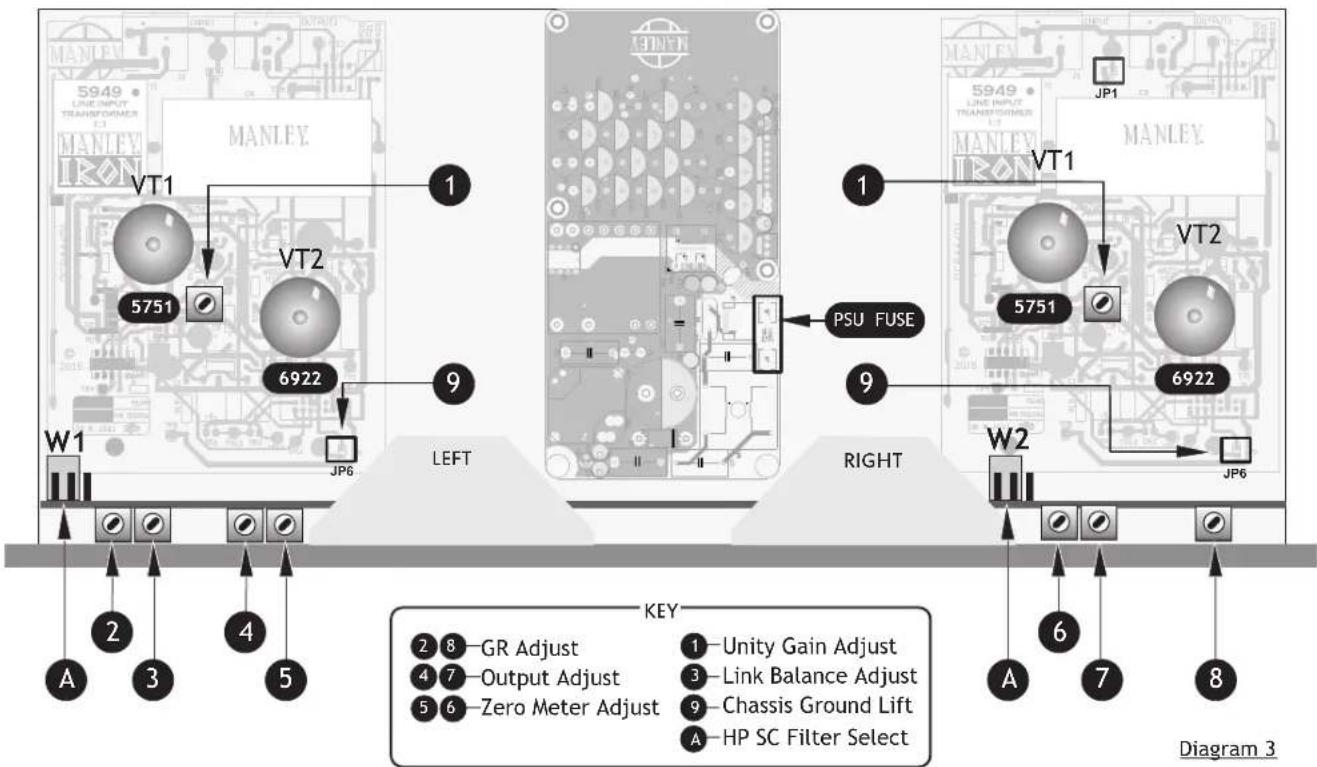
VACUUM TUBES
The ELOP+ utilizes one 5751 & one 6922 per channel. The lifespan of these tubes is in the order of 5000-6000 hours, after which time the tubes should be replaced. If the ELOP+ has become noisy, this could be related to tube wear. Consult your dealer or purchase new tubes from Manley Labs. We supply low noise and graded quality. Simply hold the tube firmly at its base and vertically pull upwards, freeing the tube from its socket. When inserting a new tube ensure all the pins are straight and align with the receptacles of the tube base before pressing down firmly to locate the tube correctly.
If necessary the Circuit Ground can be disconnected from the Chassis Ground. This practice is usually required if hum-loops cannot be cured in any other way. Removing both jumpers JP6 one on each channel will break the chassis signal ground.
A HP SC FILTER SELECT

This jumper selects either a 80Hz or 150Hz High Pass Side Chain Filter. If the Jumper is set on the two left pins leaving the right pin free 80Hz is selected (default). If the jumper is set on the two right pins leaving the left pin free, 150 Hz is selected.
PSU FUSE
The PSU fuse is a safety fuse rated at 2A (T) 250V AC. If this fuse fails the switched-mode PSU has suffered a catastrophic failure and it is unlikely that it can be repaired. The unit will have to be returned for service.
CALIBRATION / INTERNAL ADJUSTMENTS - FOR EXPERIENCED TECHNICIANS ONLY\*
Before starting any procedure, please set the front panel controls to these settings & remove the top cover; BYPASS mode, LINK OFF, REDUCTION controls counter clockwise (MIN), GAIN to 1:00 or unity, S.C. at "Flat".
THERE ARE HIGH VOLTAGES INSIDE THE ELOP+. DO NOT HOLD THE METAL PART OF THE SCREWDRIVER. DO NOT PROBE AROUND WITH THE SCREWDRIVER OR FINGERS. The unit should be switched on for about 15 minutes to allow for the correct "warming up" period. If you can use an insulated trimming tool.
1 Unity Gain Adjust
This adjusts the tube amplifier gain in all modes. Apply 1 kHz sine at 1.23 volts RMS (+4 dBm, 0 VU) to both inputs. BYPASS mode. Adjust 1 for unity gain at outputs.
4 & 7 Output Adjust
This adjusts VU meter calibration for OUTPUT. Same input, set Meter switches to OUTPUT. Adjust for 0 VU on the Meters.
This adjusts the meter zero for Reduction mode. Set Meter switches to REDUCTION. Adjust for 0 VU on the Meters.
Switch from BYPASS to IN. Meter switches to OUTPUT. Adjust GAIN controls to get +4dBu on the METERS
2 & 8 GR Adjust
This adjusts the meter in Reduction mode to reflect the actual gain reduction accurately. You will probably need to increase the oscillator 10 dB to get Limiting. Adjust REDUCTION controls to reduce the signal to -4dB. Switch METERS to REDUCTION. Adjust 2 & 8 to get -4 dB on the METERS.
3 Link Balance Adjust
This adjusts the gain of the right side chain and adjusts the side chain balance in Link. Switch the LINK ON. There should be 1 to 2 dB change in the Meters. Adjust 3 so that the meter is the same for both sides. You may have to re-adjust 2 & 8. Check that both in LINK and STEREO that both channels show the same reduction.
Final Check
This is a final check to verify that all adjustments are OK and the unit is ready for use. Confirm that 0 VU on the meters is +4 dBm with an external VU meter or VOM that reads between 1.22 and 1.23 volts AC and that gain reduction reads the same on OUTPUT and REDUCTION and that LINK or UN-LINK does not reduce the gain unevenly on the two sides. Remove the power lead and screw the top cover back on to the ELOP+.
\* Experienced Technicians Only
The calibration procedures mentioned here are to aid the servicing of the unit. They should only be attempted by a skilled Technician. These adjustments should not be attempted by the user without experience. Trimming these potentiometers without the correct understanding will result in poor performance of the unit.
10. Specifications
MANLEY ELOP+ STEREO ELECTRO-OPTICAL VACUUM TUBE LIMITER / COMPRESSOR
- ALL-TUBE audio path using a 5751 for gain, 6922 White Follower output tube (one each per channel)
- Silent Conductive Plastic GAIN control.
• Balanced MANLEY IRON Transformer coupled XLR input.
• Input impedance: 14 kOhms
• Maximum input level: +18dBu or 4.8V RMS @ 0.01% THD
• Hi-current White Follower Impedance Balanced XLR output.
• Output impedance=150 Ohms
• Maximum Output with 100 kOhm load= +30dBu @.009%THD+N, BW 22Hz-22Khz, 1Khz sine
• Maximum Output with 600 Ohm load= +20dBu @.015%THD+N, BW 22Hz-22Khz, 1Khz sine
• Output Headroom (Referenced to +4dBu)= 26dB
• Frequency Response= -0.15dB @ 10Hz, -0.1dB @ 20KHz
• Total Harmonic Distortion (1kHz sine @ +4dBu, BW 22Hz-22kHz) = 0.004 % THD+N
• Noise Floor Limiter Bypass= -90dBu (BW 22Hz-22kHz) - Noise Floor Limiter Engaged= -88dBu (BW 22Hz-22kHz) Input set to Unity gain
• Dynamic Range= 118dB
• Signal to Noise Ratio = 92dB (Referenced to +4dBu) - Bypass mode = Signal goes thru ALL-TUBE audio path (Bypasses limiter) this is not a “hardwire bypass”
• Unity Gain= Set Input Attenuator @ 1:00 o'clock
• Maximum Gain= 13 dB
• Common-Mode Rejection Ratio (CMRR)= 77dB (BW 22Hz-22Khz, +4dBu, 1Khz sine) - Limiter Ratio= 10:1
• Compressor Ratio= 3:1 - Limiter:
Attack= 15ms
Release= 200ms
- Compressor:
Attack= 75ms
Release= 200ms
- Attack/Release times measured under following conditions: 4dB of Gain Reduction, 1kHz sine, +4dbu Input level, to 63% of total.
- Attack times are faster with higher input levels and heavier gain reduction. Typically for complete release, release times increases up to a couple of seconds, depending upon the amount of previous reduction.
• Maximum Limiting (with +4dBu 1Khz sine)= 12dB
• Maximum Compression (with +4dBu 1Khz sine)= 6dB - Side-Chain High Pass Filter= 80Hz (Internal user adjust jumper to 150Hz)
• Automute warmup delay=30 seconds - Operating mains voltage= 90 to 254 VAC (internal universal power supply)
• Mains voltage Frequency= 50-60 Hz
• Power consumption= 26 Watts -
Dimensions= (w,d,h) 19" x 7 x 3 ½" (occupies 2u)
• Unit weight= 9.5 lb
• Shipping weight= 10 lb -
Recall Sheet
| ARTIST | INSTRUMENT / TRACK | DATE | |
| SONG | MIC NOTES | ENGINEER |
| ARTIST | INSTRUMENT / TRACK | DATE |
| SONG | MIC NOTES | ENGINEER |

Designed & Handcrafted in the USA
Manley Laboratories, Inc.
13880 Magnolia Avenue
Chino, CA 91710 USA
T: +1 (909) 627-4256
www.manley.com

- ELOP ® +
- CHAPTER
- PAGE
- i) An Introduction To The Manley ELOP ® + Limiter & Compressor
- ii) Manual Conventions
- iii) Notice
- Important Safety Instructions
- Getting Started
- Front Panel
- GAIN CONTROL
- 2
- REDUCTION CONTROL
- 3
- VU METER
- 4
- HP SC CONTROL
- 5
- IN / BYPASS CONTROL
- COMPRESS / LIMIT CONTROL
- METER SELECT
- POWER SWITCH
- LINK / STEREO FUNCTION
- Operational Notes
- Advanced Tricks
- Trick#1
- Trick#2
- Trick#3
- Trick#4
- Trick#5
- Questions & Troubleshooting
- Q: No Power, No Indicators?
- Q: The Unit Is Switched On, No Sound?
- Q: Levels Seem To Be Wrong, No Bottom?
- Q: Only One Channel Is Functioning?
- Q: How Can I Cure Low Frequency Hum?
- Q: I am Hearing a lot of Hiss?
- Q: ELOP+ Sounds Distorted?
- Servicing
- VACUUM TUBES
- A HP SC FILTER SELECT
- PSU FUSE
- CALIBRATION / INTERNAL ADJUSTMENTS - FOR EXPERIENCED TECHNICIANS ONLY\*
- Unity Gain Adjust
- & 7 Output Adjust
- & 8 GR Adjust
- Link Balance Adjust
- Final Check
- \* Experienced Technicians Only
- Specifications
- MANLEY ELOP+ STEREO ELECTRO-OPTICAL VACUUM TUBE LIMITER / COMPRESSOR
Brand : Manley
Model : ELOP+
Category : Uncategorized