
DXS-3600-32S - Network switch D-LINK - Free user manual and instructions
Find the device manual for free DXS-3600-32S D-LINK in PDF.


| Product Type | Layer 2/3 Managed 10Gigabit Ethernet Switch |
| Model | DXS-3600-32S |
| Ports | 32 x 10G SFP+ ports (supports 10GBASE-R) |
| Expansion Module Slots | Yes, supports DXS-3600-EM-8T (8 x 10G RJ45) and other modules |
| Management Interfaces | Console (CLI), Web UI (HTTP/HTTPS), SNMP (v1/v2c/v3), Telnet, SSH |
| Layer 2 Features | 802.1Q VLAN, GVRP, STP/RSTP/MSTP, Link Aggregation, IGMP/MLD Snooping, LLDP, ERPS, Loopback Detection |
| Layer 3 Features | Static Routing, RIP, OSPFv2/v3, BGP, VRRP, PIM, DVMRP, IGMP/MLD Proxy, ECMP, VRF |
| Quality of Service (QoS) | CoS to Queue Mapping, Port/Queue Rate Limiting, Aggregate Policer, WRED, ETS, PFC, QCN |
| Access Control Lists (ACL) | Standard/Extended IP ACL, IPv6 ACL, MAC ACL, Expert ACL, CPU ACL, VLAN ACL |
| Security Features | 802.1X, MAC Authentication, Web Authentication, Port Security, DHCP Snooping, ARP Spoofing Prevention, BPDU Attack Protection, SSH/SSL, RADIUS, TACACS+ |
| Stacking | Physical stacking (up to 4 units), Virtual stacking (SIM) |
| Green Features | Power Saving mode, Energy Efficient Ethernet (EEE) |
| Dimensions (Approx.) | 1U rackmount, 17.3 x 11.8 x 1.73 inches (440 x 300 x 44 mm) |
| Weight (Approx.) | 13.2 lbs (6.0 kg) |
| Power Supply | Dual redundant AC power supplies (100-240V, 50-60Hz) |
| Power Consumption (Max) | 130W (typical) |
| Operating Temperature | 0°C to 45°C (32°F to 113°F) |
| Storage Temperature | -40°C to 70°C (-40°F to 158°F) |
| Humidity | 10% to 90% non-condensing |
| Cooling | 3 hot-swappable fan modules (front-to-back airflow) |
| Software Release | Version 2.40 (Enhanced License mode) |
| Certifications | FCC, CE, UL, RoHS |
Frequently Asked Questions - DXS-3600-32S D-LINK
User questions about DXS-3600-32S D-LINK
0 question about this device. Answer the ones you know or ask your own.
Ask a new question about this device
Download the instructions for your Network switch in PDF format for free! Find your manual DXS-3600-32S - D-LINK and take your electronic device back in hand. On this page are published all the documents necessary for the use of your device. DXS-3600-32S by D-LINK.
USER MANUAL DXS-3600-32S D-LINK
natural_image
Line drawing of three stacked server racks (no text or symbols)Web UI Reference Guide
Product Model: DXS-3600 Series
Layer 2/3 Managed 10Gigabit Ethernet Switch
Release 2.40
Information in this document is subject to change without notice. Reproduction of this document in any manner, without the written permission of the D-Link Corporation, is strictly forbidden.
Trademarks used in this text: D-Link and the D-Link logo are trademarks of the D-Link Corporation; Microsoft and Windows are registered trademarks of the Microsoft Corporation.
Other trademarks and trade names may be used in this document to refer to either as the entities claiming the marks and the names or their products. D-Link Corporation disclaims any proprietary interest in trademarks and trade names other than its own.
© 2015 D-Link Corporation. All rights reserved.
September, 2015. P/N 651XS3632010G
Table of Contents
1. Introduction ...... 1
Audience 1
Other Documentation....1
Conventions....1
Notes, Notices, and Cautions .... 1
2. Web-based Switch Configuration....3
Management Options....3
Connecting using the Web User Interface 3
Logging onto the Web Manager ....3
Web User Interface (Web UI)....5
Areas of the User Interface....5
3. System....6
Device Information 6
Device Information....6
Temperature Status 7
CPU Status 8
System Log Entries....9
Fan Status....11
Flash, SD Card, and Memory Status....12
System Information Settings....13
Peripheral Settings....13
Port Configuration 14
Port Settings 14
Port Status 16
Port GBIC....17
Port Auto Negotiation....18
Error Disable Settings....19
Jumbo Frame....20
System Log 21
System Log Settings....21
System Log Discriminator Settings....23
System Log Server Settings 24
System Log 25
System Attack Log....26
Time and SNTP 26
Clock Settings 26
Time Zone Settings....26
SNTP Settings 28
Time Range....29
4. Management 31
User Account Settings ....31
Password Encryption 32
Login Method 32
SNMP 33
SNMP Global Settings 35
SNMP Linkchange Trap Settings 36
SNMP View Table Settings....36
SNMP Community Table Settings 37
SNMP Group Table Settings 38
SNMP Engine ID Local Settings....40
SNMP User Table Settings....40
SNMP Host Table Settings 42
RMON 43
RMON Global Settings 43
RMON Statistics Settings 43
RMON History Settings....44
RMON Alarm Settings 45
RMON Event Settings....46
Telnet/Web 47
Session Timeout 48
DHCP 48
Service DHCP 48
DHCP Class Settings....49
DHCP Server 50
DHCPv6 Server 57
DHCP Relay....61
DHCPv6 Relay....66
DHCP Auto Configuration....67
DNS....68
DNS Global Settings....68
DNS Name Server Settings....69
DNS Host Settings....70
IP Source Interface 70
File System 72
Physical Stacking....73
Virtual Stacking (SIM) 77
Single IP Settings 79
Topology 80
Firmware Upgrade 86
Configuration File Backup/Restore 87
Upload Log File....87
SMTP Settings 88
NLB FDB Settings....89
5. Layer 2 Features....91
FDB 91
Static FDB....91
MAC Address Table Settings....92
MAC Address Table....93
MAC Notification 94
VLAN....96
802.1Q VLAN....96
802.1v Protocol VLAN 96
GVRP 98
MAC VLAN....101
VLAN Interface 102
Subnet VLAN 109
Super VLAN 110
Private VLAN 111
VLAN Tunnel....113
Dot1q Tunnel 113
VLAN Mapping....114
VLAN Mapping Profile 115
STP 120
STP Global Settings 120
STP Port Settings 122
MST Configuration Identification 123
STP Instance 124
MSTP Port Information 125
ERPS (G.8032) 125
ERPS 125
ERPS Profile 129
Loopback Detection 130
Link Aggregation 131
L2 Protocol Tunnel....134
L2 Multicast Control 136
IGMP Snooping 136
MLD Snooping 144
Multicast VLAN 152
Multicast Filtering....157
LLDP 158
LLDP Global Settings 158
LLDP Port Settings 159
LLDP Management Address List....160
LLDP Basic TLVs Settings....160
LLDP Dot1 TLVs Settings....161
LLDP Dot3 TLVs Settings....162
LLDP-MED Port Settings....163
LLDP-DCBX Port Settings 164
LLDP Statistics Information 165
LLDP Local Port Information....166
LLDP Neighbor Port Information 168
- Layer 3 Features....169
ARP 169
ARP Aging Time 169
Static ARP....169
Proxy ARP 170
ARP Table....171
Gratuitous ARP 171
IPv6 Neighbor 172
Interface 173
IPv4 Interface....173
IPv6 Interface....175
Loopback Interface 179
Null Interface....180
UDP Helper 181
IP Forward Protocol 181
IP Helper Address....182
IPv4 Static/Default Route....182
IPv4 Route Table 183
IPv6 Static/Default Route....184
IPv6 Route Table 185
Route Preference....186
ECMP Load Balancing Settings....187
IPv6 General Prefix....188
IP Tunnel Settings....188
URPF Settings 190
VRF 192
VRF Settings....192
VRF Interface Settings....195
RIP 196
RIP Settings....196
RIP Distribute List....198
RIP Interface Settings....199
RIP Database 200
RIPng 200
RIPng Settings....200
RIPng Interface Settings....202
RIPng Database 203
OSPF 203
OSPFv2 203
OSPFv3 218
IP Multicast Routing Protocol....229
IGMP 229
MLD 232
IGMP Proxy....236
MLD Proxy 239
DVMRP 241
PIM....243
IPMC 266
IPv6MC 271
BGP 274
BGP Global Settings....274
BGP Aggregate Address Settings 276
BGP Network Settings 277
BGP Route Redistribution Settings 278
BGP Route Preference Settings....280
BGP Dampening Settings....280
BGP Dampening Dampened Paths Table....282
BGP Dampening Flap Statistics Table 283
BGP Reflector Settings....284
BGP Confederation Settings....285
BGP AS Path Access List Settings....285
BGP Community List Settings 286
BGP Extended Community List Settings 288
BGP Clear Settings....289
BGP Summary Table....290
BGP Routing Table 291
BGP Labels Table....296
BGP Neighbor....297
IP Route Filter 309
IP Prefix List....309
Route Map 310
Policy Route 314
VRRP Settings 315
7. Quality of Service (QoS) 318
Basic Settings 318
Port Default CoS....318
Port Scheduler Method....318
Queue Settings 320
CoS to Queue Mapping 321
Port Rate Limiting 321
Queue Rate Limiting....322
Advanced Settings 324
DSCP Mutation Map....324
Port Trust State and Mutation Binding....324
Aggregate Policer 329
Policy Map 333
Policy Binding 333
QoS PFC 334
Network QoS Class Map 334
Network QoS Policy Map 335
Network QoS Policy Binding....337
WRED 337
WRED Profile....337
WRED Queue 339
WRED Drop Counter 340
ETS 340
ETS Port Settings 340
ETS Recommend Settings 341
QCN 342
QCN CNPV Status....342
QCN CNPV Settings....343
QCN CNPV Interface Settings....345
QCN CNPV Interface Simple....346
QCN CP Interface Settings....346
QCN CP Counters 348
QCN CPID Table 348
8. Access Control List (ACL) 350
ACL Configuration Wizard 350
Step 1 - Create/Update....350
Step 2 - Select Packet Type .... 351
Step 3 - Add Rule ...... 351
Step 4 - Apply Port....384
ACL Access List....384
Standard IP ACL 385
Extended IP ACL 388
Standard IPv6 ACL 408
Extended IPv6 ACL 412
Extended MAC ACL 424
Extended Expert ACL 428
ACL Interface Access Group 456
ACL VLAN Access Map 457
ACL VLAN Filter 459
CPU ACL....460
9. Security 464
Port Security......464
Port Security Global Settings....464
Port Security Port Settings....465
Port Security Address Entries 467
802.1X....467
802.1X Global Settings 472
802.1X Port Settings 472
Authentication Sessions Information 474
Authenticator Statistics 474
Authenticator Session Statistics 475
Authenticator Diagnostics 475
AAA 476
AAA Global Settings 476
Application Authentication Settings 477
Application Accounting Settings 477
Authentication Settings 479
Accounting Settings 480
RADIUS....482
RADIUS Global Settings....482
RADIUS Server Settings....483
RADIUS Group Server Settings 484
RADIUS Statistic....486
TACACS....486
TACACS Server Settings....486
TACACS Group Server Settings 487
TACACS Statistic....488
IMPB 488
IPv4 488
IPv6 501
DHCP Server Screening 506
DHCP Server Screening Global Settings 506
DHCP Server Screening Port Settings 507
ARP Spoofing Prevention 508
BPDU Attack Protection....509
MAC Authentication 511
Web-based Access Control 512
Web Authentication....514
WAC Port Settings....515
WAC Customize Page 515
Network Access Authentication ....516
Guest VLAN 516
Network Access Authentication Global Settings....517
Network Access Authentication Port Settings 519
Network Access Authentication Sessions Information 520
Safeguard Engine 521
Safeguard Engine Settings 522
CPU Protect Counters 523
CPU Protect Sub-Interface 523
CPU Protect Type 524
Trusted Host....525
Traffic Segmentation Settings....525
Storm Control 526
DoS Attack Prevention Settings....530
SSH....531
SSH Global Settings 531
Host Key 532
SSH Server Connection....533
SSH User Settings 533
SSL 534
SSL Global Settings....535
Crypto PKI Trustpoint 536
SSL Service Policy 537
SFTP Server Settings 537
- OAM 539
CFM 539
CFM Settings 539
CFM Port Settings 546
CFM Loopback Test 547
CFM Linktrace Settings 547
CFM Packet Counter 549
CFM Counter CCM 549
CFM MIP CCM Table 550
CFM MEP Fault Table 550
Cable Diagnostics 550
Ethernet OAM 551
Ethernet OAM Settings 551
Ethernet OAM Configuration Settings 553
Ethernet OAM Event Log Table....556
Ethernet OAM Statistics Table....556
Ethernet OAM DULD Settings 557
DDM 558
DDM Settings....559
DDM Temperature Threshold Settings....559
DDM Voltage Threshold Settings 560
DDM Bias Current Threshold Settings 561
DDM TX Power Threshold Settings....561
DDM RX Power Threshold Settings 562
DDM Status Table 563
- MPLS 564
MPLS LDP Information Settings 564
MPLS LSP Trigger Information....566
MPLS Forwarding Settings 567
MPLS LDP Neighbor Password Settings....569
MPLS LDP Neighbor Targeted Settings 569
MPLS LDP Neighbor Information....570
MPLS Global Settings....571
MPLS LDP Interface Settings....571
MPLS LDP Session Information 572
MPLS LDP Statistic....573
MPLS LDP Binding Table 573
MPLS LDP Discovery Information 573
MPLS QoS Settings 574
Ping MPLS 577
Traceroute MPLS IPv4....578
- MPLS L2VPN....580
VPWS Settings 580
L2VC Interface Description....582
VPLS Settings 583
VPLS MAC Address Table....586
- Monitoring......588
Mirror Settings....588
Traffic 590
Traffic Monitoring by Direction 590
Traffic Monitoring by Type 591
Traffic Monitoring by Size 591
Traffic Monitoring by Error 592
sFlow....593
sFlow Agent Information....593
sFlow Receiver Settings 593
sFlow Sampler Settings....594
sFlow Poller Settings 595
Device Environment....596
14. Green....597
Power Saving 597
EEE 598
15. Save and Tools....600
Save Configuration 600
Firmware Upgrade & Backup....600
Firmware Upgrade from HTTP 600
Firmware Upgrade from TFTP 601
Firmware Upgrade from FTP 601
Firmware Upgrade from RCP 602
Firmware Backup to HTTP 603
Firmware Backup to TFTP 604
Firmware Backup to FTP 604
Firmware Backup to RCP 605
Configuration Restore & Backup 606
Configuration Restore from HTTP 606
Configuration Restore from TFTP 606
Configuration Restore from FTP 607
Configuration Restore from RCP 608
Configuration Backup to HTTP 609
Configuration Backup to TFTP 610
Configuration Backup to FTP 610
Configuration Backup to RCP 611
Log Backup 612
Log Backup to HTTP 612
Log Backup to TFTP 613
Log Backup to RCP 613
Ping 614
Trace Route 616
Reset....618
Reboot System 618
DLMS Settings 619
Appendix A - Password Recovery Procedure....621
Appendix B - System Log Entries 622
Appendix C - Trap Entries 655
Appendix D - RADIUS Attributes Assignment 665
Appendix E - IETF RADIUS Attributes Support....668
1. Introduction
This manual's feature descriptions are based on the software release 2.40, running in the Enhanced License (EI) Mode. The features listed here are the subset of features that are supported by the DXS-3600 Series switch.
Audience
This reference manual is intended for network administrators and other IT networking professionals responsible for managing the switch by using the Web User Interface (Web UI). The Web UI is the secondary management interface to the DXS-3600 Series switch, which will be generally be referred to simply as the “switch” within this manual. This manual is written in a way that assumes that you already have the experience and knowledge of Ethernet and modern networking principles for Local Area Networks.
Other Documentation
The documents below are a further source of information in regards to configuring and troubleshooting the switch. All the documents are available either from the CD, bundled with this switch, or from the D-Link website. Other documents related to this switch are:
• DXS-3600 Series Hardware Installation Guide
• DXS-3600 Series CLI Reference Guide
Conventions
| Convention Description | |
| Boldface Font | Indicates a button, a toolbar icon, menu, or menu item. For example: Open the File menu and choose Cancel. Used for emphasis. May also indicate system messages or prompts appearing on screen. For example: You have mail. Bold font is also used to represent filenames, program names and commands. For example: use the copy command. |
| Initial capital letter | Indicates a window name. Names of keys on the keyboard have initial capitals. For example: Click Enter. |
| Menu Name > Menu Option | Indicates the menu structure. Device > Port > Port Properties means the Port Properties menu option under the Port menu option that is located under the Device menu. |
| Blue Courier Font | This convention is used to represent an example of a screen console display including example entries of CLI command input with the corresponding output. |
Notes, Notices, and Cautions
Below are examples of the three types of indicators used in this manual. When administering your switch using the information in this document, you should pay special attention to these indicators. Each example below provides an explanatory remark regarding each type of indicator.

NOTE: A note indicates important information that helps you make better use of your device.

NOTICE: A notice indicates either potential damage to hardware or loss of data and tells you how to avoid the problem.

CAUTION: A caution indicates a potential for property damage, personal injury, or death.
2. Web-based Switch Configuration
Management Options
Connecting using the Web User Interface
Logging onto the Web Manager
Web User Interface (Web UI)
Management Options
This switch provides multiple access platforms that can be used to configure, manage and monitor networking features available on this switch. Currently there are three management platforms available and they are described below.
The Command Line Interface (CLI) through the Serial Port or remote Telnet
This switch can be managed, out-of-band, by using the console port on the front panel of the switch. Alternatively, the switch can also be managed, in-band, by using a Telnet connection to any of the LAN ports on this switch. The command line interface provides complete access to all switch management features.
SNMP-based Management
The switch can be managed with an SNMP-compatible console program. The switch supports SNMP version 1.0, version 2.0 and version 3.0. The SNMP agent decodes the incoming SNMP messages and responds to requests with MIB objects stored in the database. The SNMP agent updates the MIB objects to generate statistics and counters.
Web-based Management Interface
After successfully installing the switch, the user can configure the switch, monitor the LED panel, and display statistics graphically using a Web browser, such as Microsoft ^® Internet Explorer (version 6 and later), Mozilla Firefox (version 3 and later), Safari (version 5 and later), Google Chrome (version 5 and later), Opera (version 12 and later), or Netscape (version 8 and later).
Connecting using the Web User Interface
Most software functions of the DXS-3600 Series switches can be managed, configured and monitored via the embedded web-based (HTML) interface. Manage the switch from remote stations anywhere on the network through a standard web browser. The web browser acts as a universal access tool and can communicate directly with the switch using the HTTP or HTTPS protocol.

NOTE: The Command Line Interface (CLI) provides the functionality of managing, configuring, and monitoring all of the software features that are available on this switch.
Logging onto the Web Manager
To access the Web User Interface, simply open a standard web browser on the management PC and enter the switch's default IP address into the address bar of the browser and press the Enter key.

NOTE: The default IP address of this switch is 10.90.90.90, with a subnet mask of 255.0.0.0.

Figure 2-1 Displays entering the IP address in Internet Explorer
This will open the user authentication window, as seen below.
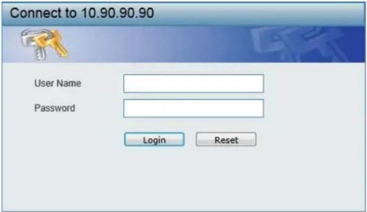
Figure 2-2 User Authentication Window
By default, there is no username or password configured on this switch. When connecting to the Web UI for the first time simply leave the User Name and Password fields blank and click the Login button.
Web User Interface (Web UI)
The user interface provides access to various switch configuration and management windows, to view performance statistics, and permits you to graphically monitor the system status.
Areas of the User Interface
The figure below shows the user interface. Three distinct areas that divide the user interface, as described in the table.
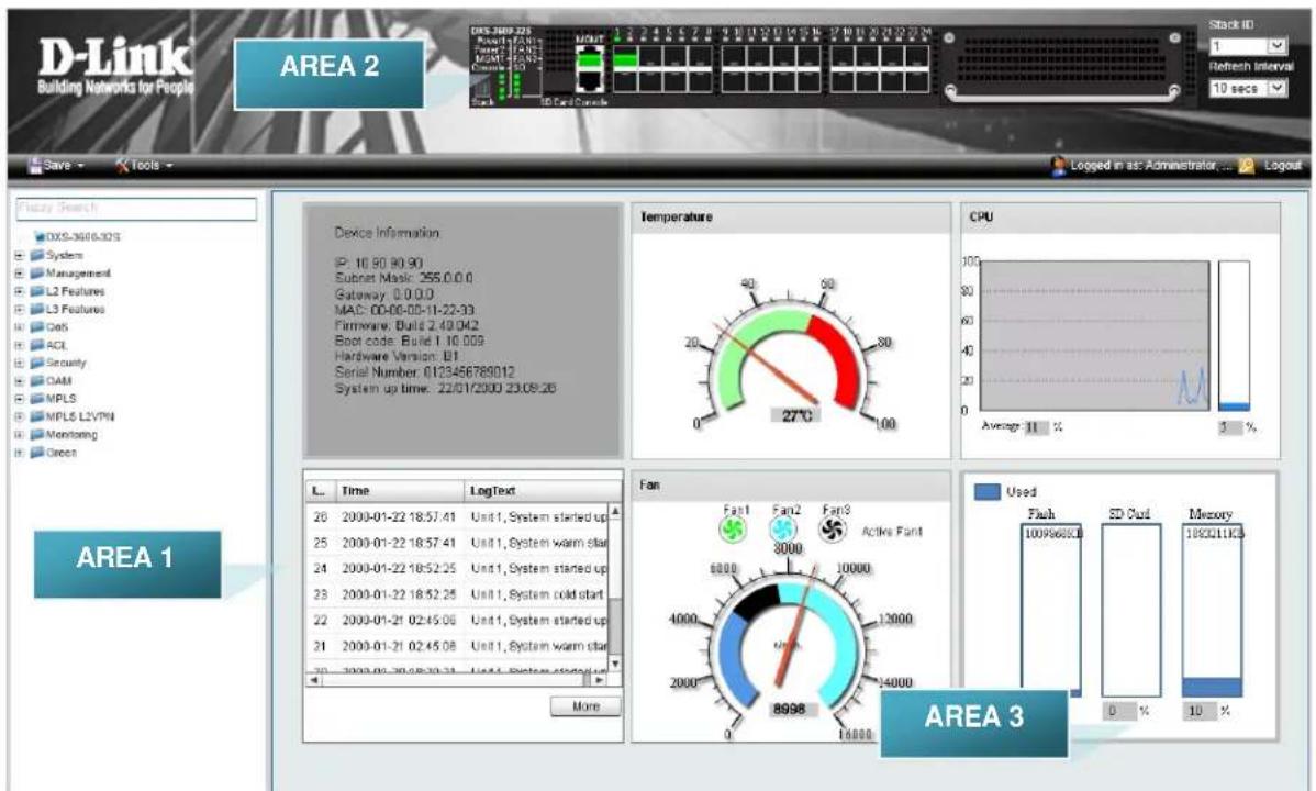
Figure 2-3 Main Web UI Window
| Area Number Description | |
| AREA 1 | In this area, a folder tree layout is displayed of functions that can be configured using the Web UI. Open folders and click the hyperlinked menu buttons to access each individual page for configuration. The DXS-3600-32S link is the default page that will display basic monitoring settings for this switch. |
| AREA 2 | In this area, a graphical near real-time image of the front panel of the switch is displayed. Some management functions, like Save and Tools are accessible here. |
| AREA 3 | In this area, the switch's configuration page can be found, based on the selection made in AREA 1. |
3. System
Device Information
System Information Settings
Peripheral Settings
Port Configuration
System Log
Time and SNTP
Time Range
Device Information
On this page, the Device Information, Temperature status, CPU, Usage status, System Log, Fan status, and Memory usage status are displayed. It appears automatically when you log on to the switch. To return to the Device Information window after viewing other windows, click the DXS-3600-32S link.
gauge
Temperature | Temperature (°C) | | :--- | | 0 | | 20 | | 40 | | 60 | | 80 | | 100 | 27°C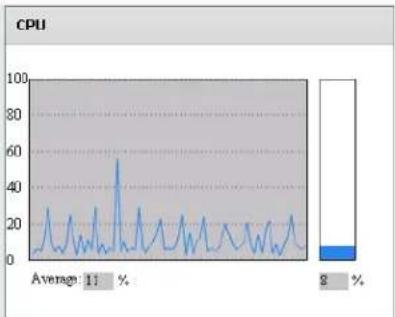
line
| Metric | Value | |--------|-------| | Average | 11 % | | 2% | 2 % |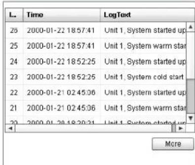
gauge
| Category | Value | |---|---| | Fan1 | 8000 | | Fan2 | 10000 | | Fan3 | 12000 | | Active:Fan1 | 8998 |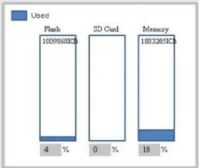
bar_stacked
| Category | Percentage (%) | | :--- | :--- | | Flash | 1009868KB | | SD Card | 0 | | Memory | 1833205KB | | Used | 4 | | Used | 10 |Figure 3-1 Device Information Window
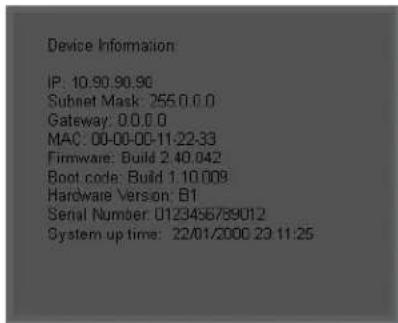
Device Information
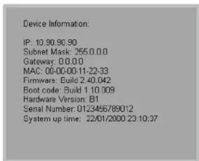
In the Device Information section, the user can view a list of basic information regarding the switch.
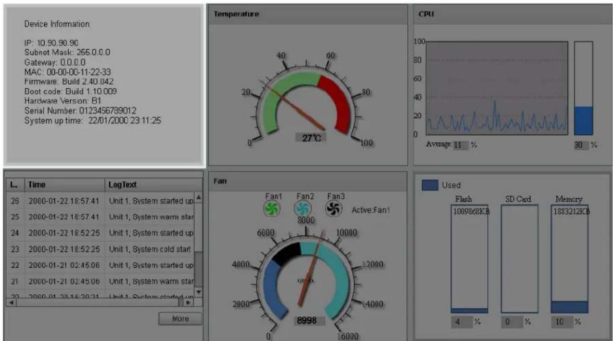
Figure 3-2 Device Information (Highlight) Window
In the Device Information section, the following display parameters are available:
| Parameter Description | |
| IP Address | Here the IP address of the switch's main interface is displayed. |
| Subnet Mask | Here the Subnet Mask of the switch's main interface is displayed. |
| Gateway | Here the Gateway IP address of the switch's main interface is displayed. |
| MAC Address | Here the MAC address of the switch is displayed. |
| Firmware Version | Here the Firmware version of the switch is displayed. |
| Boot Code Version | Here the Boot Code of the switch is displayed. |
| Hardware Version | Here the Hardware version of the switch is displayed. |
| Serial Number | Here the Serial number of the switch is displayed. |
| System Up Time | Here the System's up time is displayed. |
Temperature Status
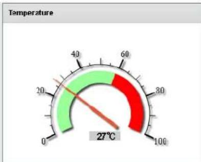
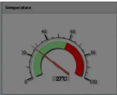
In the Temperature section, the user can view a real-time display of the switch's internal temperature. The temperature of the switch is mainly influenced by two factors: (1) the environment, and (2) the internal air-flow of the switch. In the DXS-3600 Series Hardware Installation Guide, there are some guidelines that can assist the user with the installation of this switch in a temperature friendly environment. The fan modules, installed in this switch, have temperature sensors built-in that automatically controls the air-flow inside the switch.
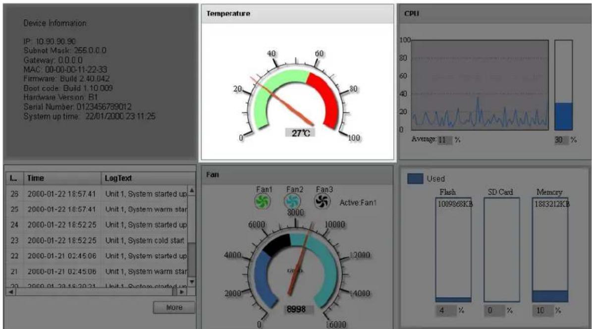
Figure 3-3 Temperature Status Window
In the Temperature section, the following display parameters are available:
| Parameter Description | |
| Percentage Display | In this graphic, the reading is divided into percentage sections. The green area is known as the ‘safe’ area. This area ranges from 0% to 60%. This is the optimum temperature range recommended for this switch. |
| Temperature | Below the percentage gauge needle, the accurate temperature reading, for this switch, is displayed in degrees Celsius. |
| Warning Section | In this graphic, the reading is divided into percentage sections. The red area is known as the ‘warning’ area. This area ranges from 60% to 100%. It is recommended not to allow the switch to run this hot, to avoid component damage. |
CPU Status
In the CPU section, the user can view a real-time display of the switch's CPU usage. There are a number of factors that can influence a depleted CPU usage. One of those factors is network broadcasts. In the DXS-3600 Series CLI Reference Guide there is an abundance of features that can be enabled to prevent this problem from occurring.
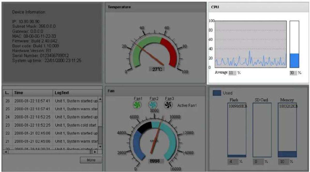
Figure 3-4 CPU Status Window
In the CPU section, the following display parameters are available:
| Parameter Description | |
| Percentage Display | In this graphic, the reading is divided into percentage sections. This area ranges from 0% to 100%. |
| Average | Below the CPU percentage line chart, we find an accurate display of the average CPU usage percentage. |
| Percentage Bar | In this graphic, an accurate reading of the real-time CPU usage percentage is displayed. |
System Log Entries
In the System Log section, the user can view a list of System log entries, generated by the switch, when certain events have occurred.
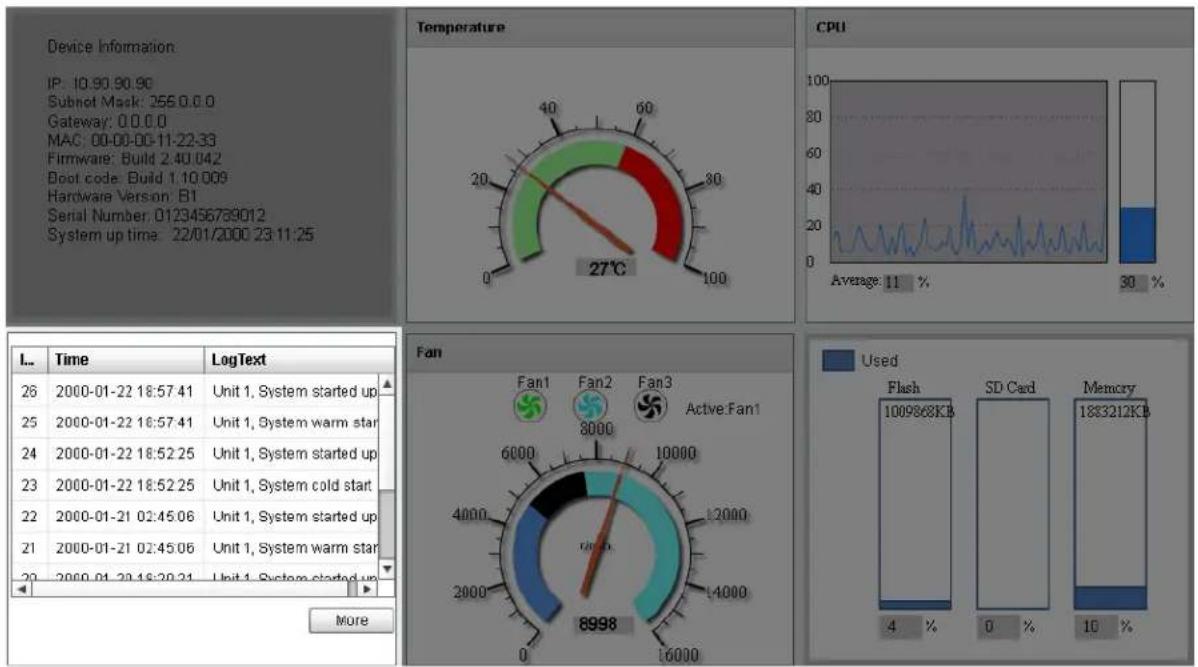
Figure 3-5 System Log Window
In the System Log section, the following display parameters are available:
| Parameter Description | |
| Entry Number | Every log entry has a specific entry number, generated when the log entry was added to the System log entry display. Here the System log entry number is displayed in reverse order. |
| Time | Here the specific date and time of the log entry is displayed. |
| Log Text | Here the log entry description is displayed. |
Click the More button to view a larger display of the complete System Log section.
After clicking the More button, the following window will appear:
| Index | Time | LogText |
| 4 | 2013-06-26 06:06:14 | System started up |
| 3 | 2013-06-26 06:06:14 | System cold start |
| 2 | 2013-06-26 03:28:50 | System started up |
| 1 | 2013-06-26 03:28:50 | System warm start |
| 1/1<<<>1go | ||
Figure 3-6 System Log (More) Window
Click the Close button to exit the larger display.
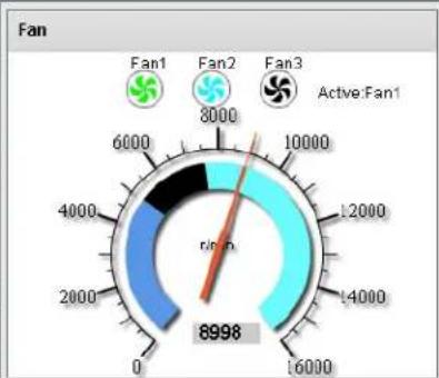
Fan Status
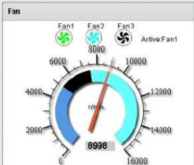
In the Fan section, the user can view a real-time display of the switch's fan(s) status. A maximum of 3 fans can be installed in this switch. In this real-time graphic, we observe the status and speed of the three fans installed.
gauge
Temperature | Temperature (°C) | | :--- | | 27 | | 30 | | 40 | | 60 | | 80 | | 100 |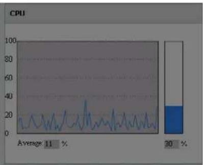
line
| Category | Value | | -------- | ----- | | Average | 11 | | % | 20 |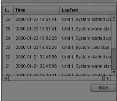
gauge
| Rating | Value | | :--- | :--- | | 0 | 8998 | | 2000 | 4000 | | 4000 | 6000 | | 6000 | 8000 | | 8000 | 10000 | | 10000 | 12000 | | 12000 | 14000 | | Active Fan1 | 8998 |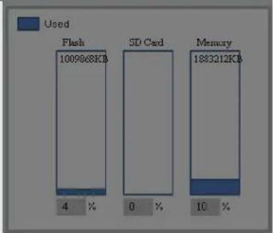
bar_stacked
| Category | Percentage (%) | | :--- | :--- | | Flash | 1009868KB | | SD Cad | 0 | | Memory | 1883212KB | | Used | 4 | | Used | 0 | | Used | 10 |Figure 3-7 Fan Status Window
In the Fan section, the following display parameters are available:
| Parameter Description | |
| Fan Number | At the top of this graphic, the list of installed fans is displayed. After clicking on any specific fan icon, the real-time RPM gauge of that fan will be displayed. Also after clicking on a fan icon, the Active Fan display parameter will change accordingly. |
| RPM Graph | In this graph (gauge display), we observe the RPM speed at which the selected fan is working at. |
| RPM Reading | At the bottom of the graphics, we observe the accurate real-time display of the RPM value for a specific fan. |
Flash, SD Card, and Memory Status
In this section, the user can view a real-time graphic that represents the memory usage for the Flash, SD Card, and RAM Memory.
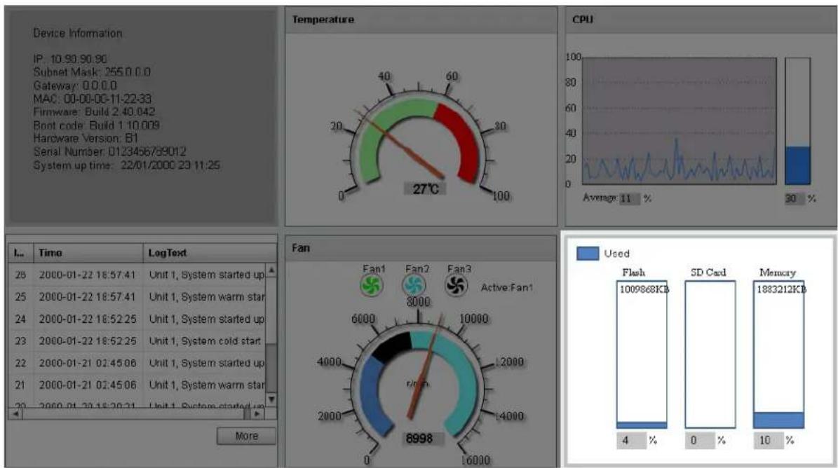
Figure 3-8 Flash, SD Card, and Memory Status Window
In this section, the following display parameters are available:
| Parameter Description | |
| Used | This displays the color that represents the used memory allocation. |
| Flash | This displays the used and unused space of the Flash. The more accurate percentage display can be found below the graphic. |
| SD Card | This displays the used and unused space of the SD Card. The more accurate percentage display can be found below the graphic. |
| Memory | This displays the used and unused space of the Memory. The more accurate percentage display can be found below the graphic. |
System Information Settings
This window is used to view and configure the system information settings and management interface configuration settings.
To view the following window, click System > System Information Settings, as shown below:
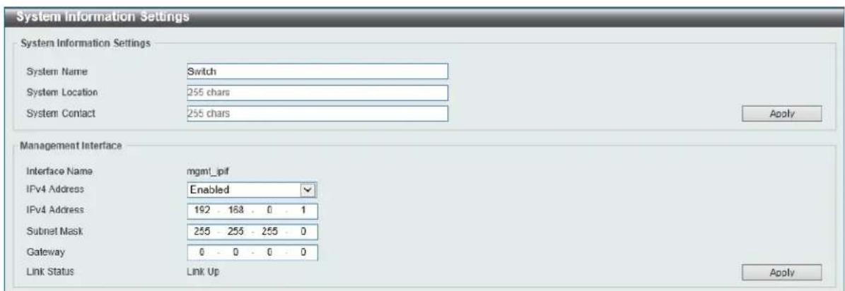
Figure 3-9 System Information Settings Window
The fields that can be configured in System Information Settings are described below:
| Parameter Description | |
| System Name | Enter a system name for the Switch, if so desired. This name will identify it in the Switch network. |
| System Location | Enter the location of the Switch, if so desired. |
| System Contact | Enter a contact name for the Switch, if so desired. |
Click the Apply button to accept the changes made.
The fields that can be configured in Management Interface are described below:
| Parameter Description | |
| IPv4 Address | Select to enable or disable this interface here. When enabled, enter the IPv4 address for this interface here. |
| Subnet Mask | Enter the IPv4 subnet mask for this interface here. |
| Gateway | Enter the gateway IPv4 address for this interface here. |
Click the Apply button to accept the changes made.
Peripheral Settings
This window is used to view and configure the environment trap settings and environment temperature threshold settings.
To view the following window, click System > Peripheral Settings, as shown below:
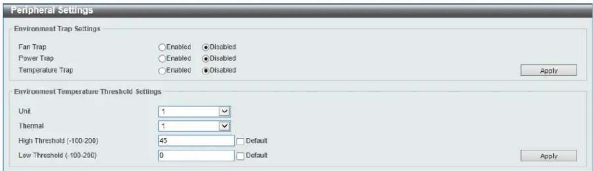
Figure 3-10 Peripheral Settings Window
The fields that can be configured in Environment Trap Settings are described below:
| Parameter Description | |
| Fan Trap | Click to enable or disable the fan trap state for waning fan event (fan failed or fan recover). |
| Power Trap | Click to enable or disable the power trap state for waning power event (power failed or power recover). |
| Temperature Trap | Click to enable or disable the temperature trap state for warning temperature event (temperature exceeds the thresholds or temperature recover). |
Click the Apply button to accept the changes made.
The fields that can be configured in Environment Temperature Threshold Settings are described below:
| Parameter Description | |
| Unit | Select the switch unit that will be used for this configuration here. |
| Thermal | Select the thermal sensor ID. |
| High Threshold | Enter the high threshold value of the warning temperature setting. The range is from -100 to 200 Celsius degree. Tick the Default check box to return to the default value. |
| Low Threshold | Enter the low threshold value of the warning temperature setting. The range is from -100 to 200 Celsius degree. Tick the Default check box to return to the default value. |
Click the Apply button to accept the changes made.
Port Configuration
Port Settings
This window is used to view and configure the switch's port settings.

NOTE: The 10M and 100M speed options are only applicable when connecting to the Management Port (Mgmt 0) or when the DXS-3600-EM-8T expansion module is used.
To view the following window, click System > Port Configuration > Port Settings, as shown below:
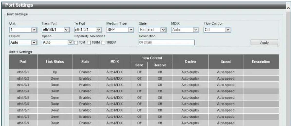
Figure 3-11 Port Settings Window
The fields that can be configured are described below:
| Parameter Description | |
| Unit | Select the stacking unit ID of the switch that will be configured here. |
| From Port ~ To Port | Select the appropriate port range used for the configuration here. |
| Medium Type | Select the port medium type here. Options to choose from are RJ45 and SFP.Note: Selecting the SFP option, includes the use of SFP+ transceivers for 10G connectivity. |
| State | Select this option to enable or disabled the physical port here. |
| MDIX | Select the Medium Dependent Interface Crossover (MDIX) option here. Options to choose from are Auto, Normal, and Cross.Auto - Select this option for auto-sensing of the optimal type of cabling.Normal - Select this option for normal cabling. If this option is selected, the port is in the MDIX mode and can be connected to a PC's NIC using a straight-through cable or a port (in the MDI mode) on another switch through a cross-over cable.Cross - Select this option for cross cabling. If this option is selected, the port is in the MDI mode and can be connected to a port (in the MDIX mode) on another switch through a straight cable. |
| Flow Control | Select to either turn flow control On or Off here. Ports configured for full-duplex use 802.3x flow control, half-duplex ports use back-pressure flow control, and Auto ports use an automatic selection of the two. |
| Duplex | Select the duplex mode used here. Options to choose from are Auto, Half, and Full. |
| Speed | Select the port speed option here. This option will manually force the connection speed on the selected port to only connect at the speed specified here.Options to choose from are Auto, 10M, 100M, 1000M, 1000M Master, 1000M Slave, 10G, 10G Master, 10G Slave, and 40G.TheMastersetting will allow the port to advertise capabilities related to duplex, speed and physical layer type. The master setting will also determine the master and slave relationship between the two connected physical layers. This relationship is necessary for establishing the timing control between the two physical layers. The timing control is set on a master physical layer by a local source.TheSlavesetting uses loop timing, where the timing comes from a data stream received from the master. If one connection is set for master, the other side of the connection must be set for slave. Any other configuration will result in a link down status for both ports.Auto: Specifies that for copper ports, auto-negotiation will start to negotiate the speed and flow control with its link partner. For fiber ports, auto-negotiation will start to negotiate the clock and flow control with its link partner.10M: Specifies to force the port speed to 10Mbps. This option is only available for 10Mbps copper connections.100M: Specifies to force the port speed to 100Mbps. This option is only available for 100Mbps copper connections.1000M: Specifies to force the port speed to 1Gbps. This option is only available for 1Gbps fiber connections.1000M Master: Specifies to force the port speed to 1Gbps and operates as the master, to facilitate the timing of transmit and receive operations. This option is only available for 1Gbps copper connections.1000M Slave: Specifies to force the port speed to 1Gbps and operates as the master, to facilitate the timing of transmit and receive operations. This option is only available for 1Gbps copper connections.10G: Specifies to force the port speed to 10Gbps. This option is only available for 10Gbps fiber connections.10G Master: Specifies to force the port speed to 10Gbps and operates as the master, to facilitate the timing of transmit and receive operations. This option is only available for 10Gbps copper connections.10G Slave: Specifies to force the port speed to 10Gbps and operates as the slave, to facilitate the timing of transmit and receive operations. This option is only available for 10Gbps copper connections.40G: Specifies to force the port speed to 40Gbps. This option is only available for 40Gbps fiber connections. |
| Capability Advertised | When theSpeedis set toAuto, these capabilities are advertised during auto-negotiation. |
| Description | Enter a 64 characters description for the corresponding port here. |
Click the Apply button to accept the changes made.
Port Status
This window is used to view the switch's physical port status and settings.
To view the following window, click System > Port Configuration > Port Status, as shown below:
| Port | Status | MAC Address | VLAN | Flow Control Operator | Duplex | Speed | Type | |
| Send | Receive | |||||||
| eth 1/0/1 | Connected | 00-00-00-11-23-33 | 1 | Off | Off | Auto-Full | Auto-16G | 10GBASE-R |
| eth 1/0/2 | Not-Connected | 00-00-00-11-23-34 | 1 | Off | Off | Auto | Auto | 10GBASE-R |
| eth 1/0/3 | Not-Connected | 00-00-00-11-23-35 | 1 | Off | Off | Auto | Auto | 10GBASE-R |
| eth 1/0/4 | Not-Connected | 00-00-00-11-23-36 | 1 | Off | Off | Auto | Auto | 10GBASE-R |
| eth 1/0/5 | Not-Connected | 00-00-00-11-23-37 | 1 | Off | Off | Auto | Auto | 10GBASE-R |
| eth 1/0/6 | Not-Connected | 00-00-00-11-23-38 | 1 | Off | Off | Auto | Auto | 10GBASE-R |
| eth 1/0/7 | Not-Connected | 00-00-00-11-23-39 | 1 | Off | Off | Auto | Auto | 10GBASE-R |
| eth 1/0/8 | Not-Connected | 00-00-00-11-23-3A | 1 | Off | Off | Auto | Auto | 10GBASE-R |
| eth 1/0/9 | Not-Connected | 00-00-00-11-23-3B | 1 | Off | Off | Auto | Auto | 10GBASE-R |
| eth 1/0/10 | Not-Connected | 00-00-00-11-23-3C | 1 | Off | Off | Auto | Auto | 10GBASE-R |
| eth 1/0/11 | Not Connected | 00-00-00-11-23-3D | 1 | Off | Off | Auto | Auto | 10GBASE-R |
| eth 1/0/12 | Not Connected | 00-00-00-11-23-3E | 1 | Off | Off | Auto | Auto | 10GBASE-R |
| eth 1/0/13 | Not Connected | 00-00-00-11-23-3F | 1 | Off | Off | Auto | Auto | 10GBASE-R |
| eth 1/0/14 | Not Connected | 00-00-00-11-23-40 | 1 | Off | Off | Auto | Auto | 10GBASE-R |
| eth 1/0/15 | Not Connected | 00-00-00-11-23-41 | 1 | Off | Off | Auto | Auto | 10GBASE-R |
| eth 1/0/16 | Not Connected | 00-00-00-11-23-42 | 1 | Off | Off | Auto | Auto | 10GBASE-R |
| eth 1/0/17 | Not Connected. . . . . . . . . . . . . . . . . . . . . . . . . . . . . . . . . . . . . . . . . . . . . . . . . . . . . . . . . . . . . . . . . . . . . . . . . . . . . . . . . . . . . . . . . . . . . . . . . . . . . eth 1/3/29. Not Connected. 9: 9: 9: 9: 9: 9: 9: 9: 9: 9: 9: 9: 9: 9: 9: 9: 9: 9: 9: 9: 9: 9: 9: 9: 9: 9: 9: 9: 9: 9: 9: 9: 9: 9: A Not connected. Not connected. Not connected. Not connected. Not connected. Not connected. Not connected. Not connected. Not connected. Not connected. Not connected. Not connected. Not connected. Not connected. Not connected. Not connected. Not connected. Not connected. Not connected. Not connected. Not connected. Not connected. Not connected. Not connected. Not connected. Not connected. Not connected. Not connected. Not connected. Not connected. Not connected. Not connected. Not connected. Not connected. No or not connected. No or not connected. No or not connected. No or not connected. No or not connected. No or not connected. No or not connected. No or not connected. No or not connected. No or not connected. No or not connected. No or not connected. No or not connected. No or not connected. No or not connected. No or not connected. No or not connected. No or not connected. No or not connected. No or not connected. No or no or no connections to the network of the network of the network of the network of the network of the network of the network of the network of the network of the network of the network of the network of the network of the network of the network of the network of the network of the network of the network of the network of the network of the network of the network of the network of the network of the network of the network of the network of the network of the network of the network of the network of the network of the network of a network of a network of a network of a network of a network of a network of a network of a network of a network of a network of a network of a network of a network of a network of a network of a network of a network of a network of a network of a network of a network of a network of a network of a network of a network of a network of a network of a network of a network of a network of a network of a network of a network of a networks, and there is no connection between them in this case. | |||||||
Figure 3-12 Port Status Window
The fields that can be configured are described below:
| Parameter Description | |
| Unit | Select the stacking unit ID of the switch that will be displayed here. |
Port GBIC
This window is used to view active GBIC information found on each applicable physical port of this switch. To view the following window, click System > Port Configuration > Port GBIC, as shown below:
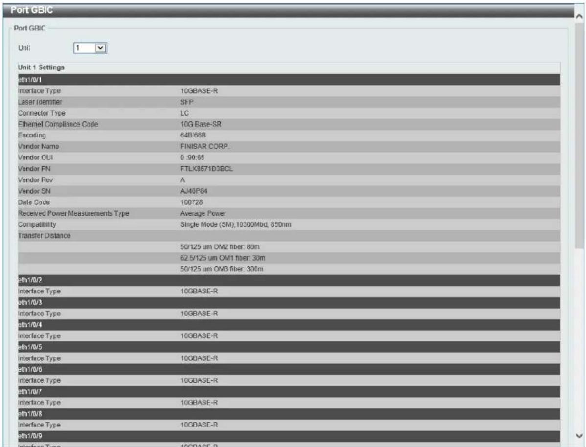
Figure 3-13 Port GBIC Window
The fields that can be configured in Port GBIC are described below:
| Parameter Description | |
| Unit | Select the switch unit that will be used for this display here. |
Port Auto Negotiation
This window is used to view detailed port auto-negotiation information.
To view the following window, click System > Port Configuration > Port Auto Negotiation, as shown below:
| Port Auto Negotiation | ||||||||
| Unit 1 Note: AN: Auto Negotiation; RS: Remote Signaling; CS: Config Status; CB: Capability Bits; CAB: Capability Advertised Bits; CRB: Capability Received Bits; RFA: Remote Fault Advertised; RFR: Remote Fault Received | ||||||||
| Unit 1 Settings | ||||||||
| Port | AN | RS | CS | CB | CAB | CRB | RFA | RFR |
| eth1/0/1 | Enabled | Not Detected | - | - | - | Disabled | NoError | |
| eth1/0/2 | Enabled | Not Detected | - | - | - | Disabled | NoError | |
| eth1/0/3 | Enabled | Not Detected | - | - | - | Disabled | NoError | |
| eth1/0/4 | Enabled | Not Detected | - | - | - | Disabled | NoError | |
| eth1/0/5 | Enabled | Not Detected | - | - | - | Disabled | NoError | |
| eth1/0/6 | Enabled | Not Detected | - | - | - | Disabled | NoError | |
| eth1/0/7 | Enabled | Not Detected | - | - | - | Disabled | NoError | |
| eth1/0/8 | Enabled | Not Detected | - | - | - | Disabled | NoError | |
| eth1/0/9 | Enabled | Not Detected | - | - | - | Disabled | NoError | |
| eth1/0/10 | Enabled | Not Detected | - | - | - | Disabled | NoError | |
| eth1/0/11 | Enabled | Not Detected | - | - | - | Disabled | NoError | |
| eth1/0/12 | Enabled | Not Detected | - | - | - | Disabled | NoError | |
| eth1/0/13 | Enabled | Not Detected | - | - | - | Disabled | NoError | |
| eth1/0/14 | Enabled | Not Detected | - | - | - | Disabled | NoError | |
| eth1/0/15 | Enabled | Not Detected | - | - | - | Disabled | NoError | |
| eth1/0/16 | Enabled | Not Detected | - | - | - | Disabled | NoError | |
| eth1/0/17 | Enabled | Not Detected | - | - | - | Disabled | NoError | |
| eth1/0/18 | Enabled | Not Detected | - | - | - | Disabled | NoError | |
| eth1/0/19 | Enabled | Not Detected | - | - | - | Disabled | NoError | |
| eth1/0/20.00.00.00.00.00.00.00.00.00.00.00.00.00.00.00.00.00.00.00.00.00.00.00.00.00.00.00.00.00.00.00.00.00.01.22.22.22.22.22.22.22.22.22.22.22.22.22.22.22.22.22.22.22.22.22.22.22.22.22.22.22.22.22.22.22.22.22.22, 23, 24, 25, 26, 27, 28, 29, 30, 31, 32, 33, 34, 35, 36, 37, 38, 39, 40, 41, 42, 43, 44, 45, 46, 47, 48, 49, 50, 51, 52, 53, 54, 55, 56, 57, 58, 59, 60, 61, 62, 63, 64, 65, 66, 67, 68, 69, 70, 71, 72, 73, 74, 75, 76, 77, 78, 79, 80, 81, 82, 83, 84, 85, 86, 87, 88, 89, 90, 91, 92, 93, 94, 95, 96, 97, 98, 99, 100, 101, 102, 103, 104, 105, 106, 107, 108, 109, 110, 111, 112, 113, 114, 115, 116, 117, 118, 119, 120, 121, 122, 123, 124, 125, 126, 127, 128, 129, 130, 131, 132, 133, 134, 135, 136, 137, 138, 139, 140, 141, 142, 143, 144, 145, 146, 147, 148, 149, 150, 151, 152, 153, 154, 155, 156, 157, 158, 159, 160, 161, 162, 163, 164, 165, 166, 167, 168, 169, 170, 171, 172, 173, 174, 175, 176, 177, 178, 179, 180 , [a] [b] [c] [d] [e] [f] [g] [h] [i] [j] [k] [l] [m] [n] [o] [p] [q] [r] [s] [t] [u] [v] [w] [x] [y] [z] [a] [a] [a] [a] [a] [a] [a] [a] [a] [a] [a] [a] [a] [a] [a] [a] [a] [a] [a] [a] [a] [a] [a] [a] [a] [a] [a] [a] [a] [a] [a] [a] [a] [a] | ||||||||
Figure 3-14 Port Auto Negotiation Window
The fields that can be configured are described below:
| Parameter Description | |
| Unit | Select the stacking unit ID of the switch that will be displayed here. |
Error Disable Settings
This window is used to view and configure the error recovery for causes and to configure the recovery interval.
To view the following window, click System > Port Configuration > Error Disable Settings, as shown below:
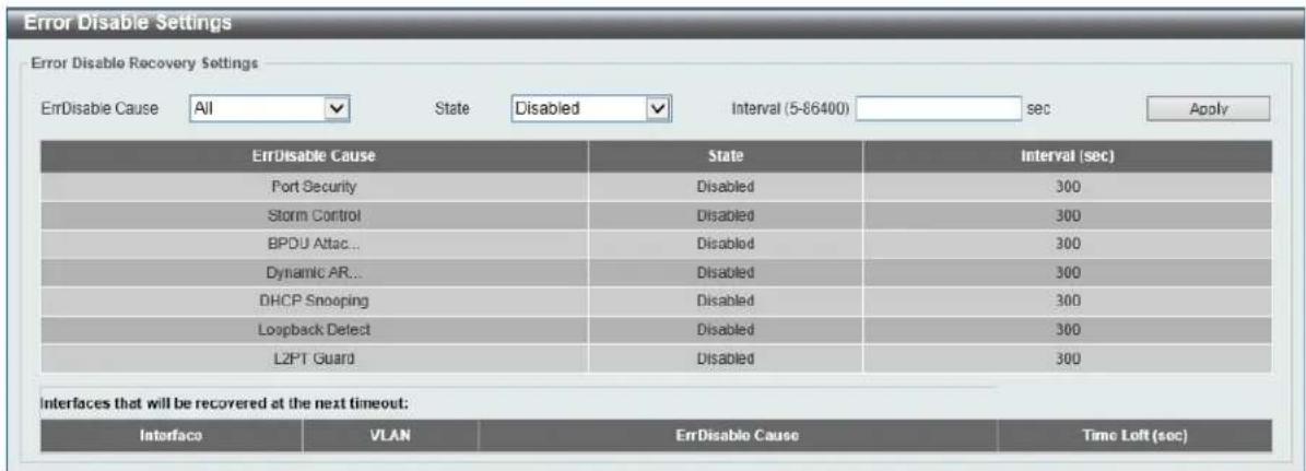
Figure 3-15 Error Disable Settings Window
The fields that can be configured in Error Disable Recovery Settings are described below:
| Parameter Description | |
| ErrDisable Cause | Select the error disabled cause here. Options to choose from are Port Security, Storm Control, BPDU Attack Protection, Dynamic ARP Inspection, DHCP Snooping, and Loopback Detect. |
| State | Select the enable or disable the error disabled recovery feature here. |
| Interval | Enter the time, in seconds, to recover the port from the error state caused by the specified module. The range is from 5 to 86400. |
Click the Apply button to accept the changes made.
Jumbo Frame
This window is used to view and configure the Jumbo Frame size and settings. The switch supports jumbo frames. Jumbo frames are Ethernet frames with more than 1,518 bytes of payload. The switch supports jumbo frames with a maximum frame size of up to 12288 bytes.
To view the following window, click System > Port Configuration > Jumbo Frame, as shown below:
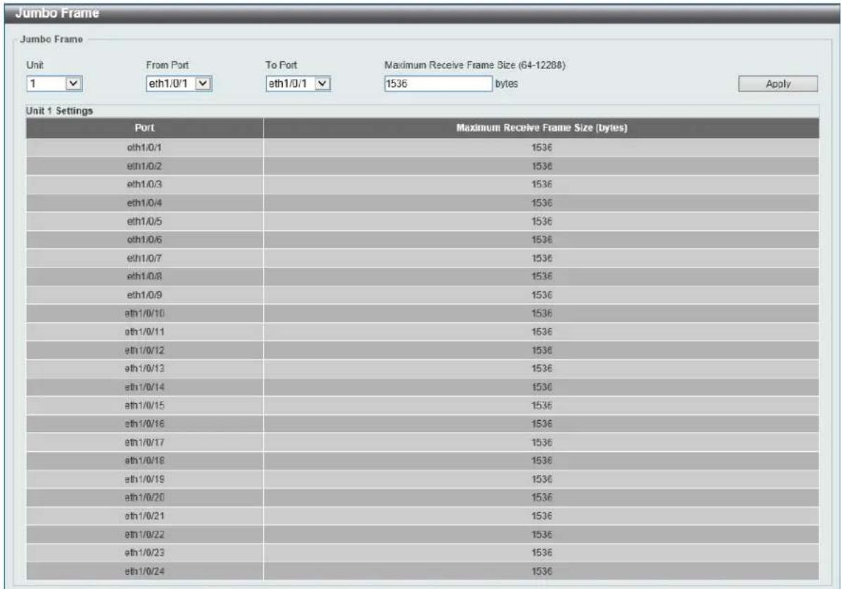
Figure 3-16 Jumbo Frame Window
The fields that can be configured are described below:
| Parameter Description | |
| Unit | Select the stacking unit ID of the switch that will be configured here. |
| From Port ~ To Port | Select the appropriate port range used for the configuration here. |
| Maximum Receive Frame Size | Enter the maximum receive frame size value here. This value must be between 64 and 12288 bytes. By default, this value is 1536 bytes. |
Click the Apply button to accept the changes made.
System Log
System Log Settings
This window is used to view and configure the system's log settings.
To view the following window, click System > System Log > System Log Settings, as shown below:
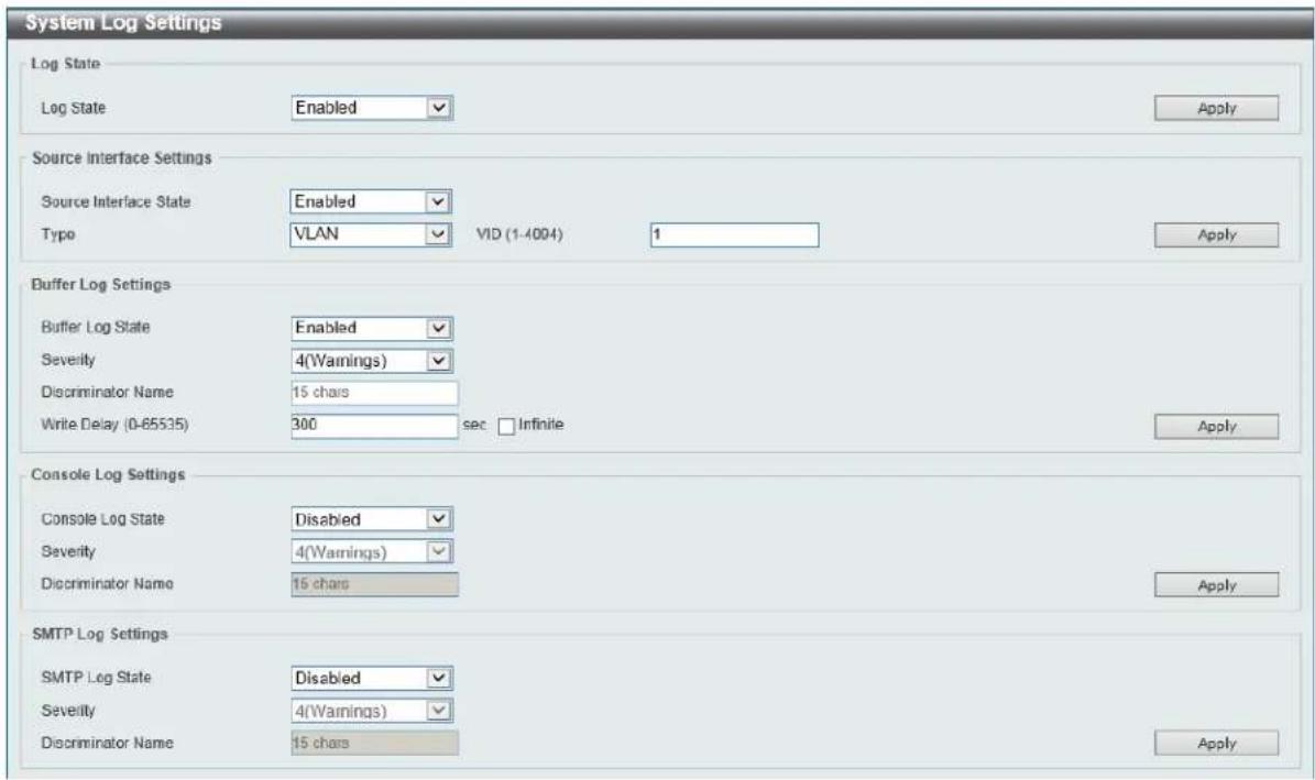
Figure 3-17 System Log Settings Window
The fields that can be configured for Log State are described below:
| Parameter Description | |
| Log State | Select the enable or disable the system log feature's global state here. |
Click the Apply button to accept the changes made.
The fields that can be configured for Source Interface Settings are described below:
| Parameter Description | |
| Source Interface State | Select this option to enable or disable the source interface's global state. |
| Type | Select the type of interface that will be used. Options to choose from are Loopback, Mgmt, and VLAN. |
| VID | Enter the interface's VID used here. For loopback interfaces this ID can be from 1 to 8. For the management (Mgmt) interface this value is always 0. For VLAN interfaces this value is from 1 to 4094. |
Click the Apply button to accept the changes made.
The fields that can be configured for Buffer Log Settings are described below:
| Parameter Description | |
| Buffer Log State | Select whether the enable or disable the buffer log's global state here. Options to choose from are Enable, Disabled, and Default. When selecting the Default option, the buffer log's global state will follow the default behavior. |
| Severity | Select the severity value of the type of information that will be logged. Options to choose from are 0 (Emergencies), 1 (Alerts), 2 (Critical), |
| 3 (Errors), 4 (Warnings), 5 (Notifications), 6 (Informational), and 7 (Debugging). | |
| Discriminator Name | Enter the discriminator name used here. This name can be up to 15 characters long. |
| Write Delay | Enter the log's write delay value here. This value must be between 0 and 65535 seconds. By default, this value is 300 seconds. Tick the Infinite option, to disable the write delay feature. |
Click the Apply button to accept the changes made.
The fields that can be configured for Console Log Settings are described below:
| Parameter Description | |
| Console Log State | Select whether the enable or disable the console log's global state here. |
| Severity | Select the severity value of the type of information that will be logged. Options to choose from are 0 (Emergencies), 1 (Alerts), 2 (Critical), 3 (Errors), 4 (Warnings), 5 (Notifications), 6 (Informational), and 7 (Debugging). |
| Discriminator Name | Enter the discriminator name used here. This name can be up to 15 characters long. |
Click the Apply button to accept the changes made.
The fields that can be configured for SMTP Log Settings are described below:
| Parameter Description | |
| SMTP Log State | Select whether the enable or disable the SMTP log's global state here. |
| Severity | Select the severity value of the type of information that will be logged. Options to choose from are 0 (Emergencies), 1 (Alerts), 2 (Critical), 3 (Errors), 4 (Warnings), 5 (Notifications), 6 (Informational), and 7 (Debugging). |
| Discriminator Name | Enter the discriminator name used here. This name can be up to 15 characters long. |
Click the Apply button to accept the changes made.
System Log Discriminator Settings
This window is used to view and configure the system log's discriminator settings.
To view the following window, click System > System Log > System Log Discriminator Settings, as shown below:
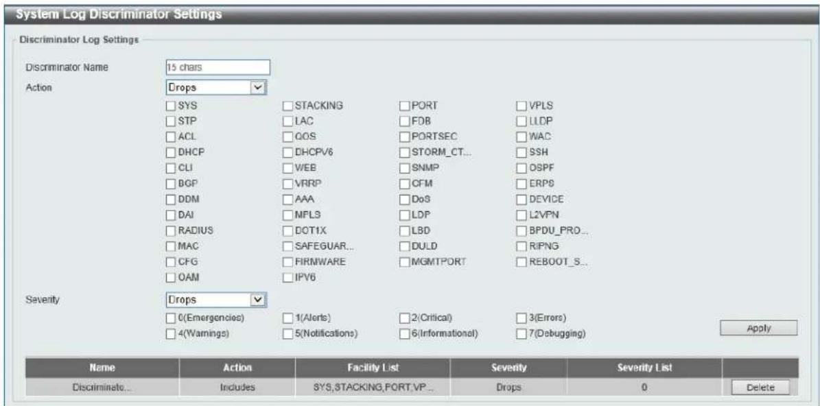
Figure 3-18 System Log Discriminator Settings Window
The fields that can be configured are described below:
| Parameter Description | |
| Discriminator Name | Enter the discriminator name here. This name can be up to 15 characters long. |
| Action | Select the facility's behavior option and the type of facility that will be associated with the selected behavior here. Behavior options to choose from are Drops and Includes. |
| Severity | Select the severity behavior option and the value of the type of information that will be logged. Behavior options to choose from are Drops and Includes. Severity value options to choose from are 0 (Emergencies), 1 (Alerts), 2 (Critical), 3 (Errors), 4 (Warnings), 5 (Notifications), 6 (Informational), and 7 (Debugging). |
Click the Apply button to accept the changes made.
Click the Delete button to delete the specified entry.
System Log Server Settings
This window is used to view and configure system log's server settings.
To view the following window, click System > System Log > System Log Server Settings, as shown below:
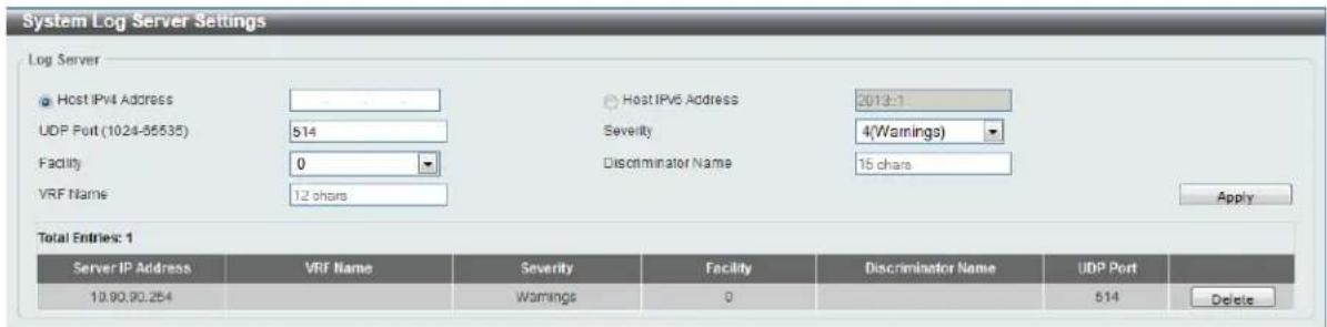
Figure 3-19 System Log Server Settings Window
The fields that can be configured are described below:
| Parameter Description | |
| Host IPv4 Address | Enter the system log server's IPv4 address here. |
| Host IPv6 Address | Enter the system log server's IPv6 address here. |
| UDP Port | Enter the system log server's UDP port number here. This value must be between 1024 and 65535. By default, this value is 514. |
| Severity | Select the severity value of the type of information that will be logged. Options to choose from are 0 (Emergencies), 1 (Alerts), 2 (Critical), 3 (Errors), 4 (Warnings), 5 (Notifications), 6 (Informational), and 7 (Debugging). |
| Facility | Select the facility value here. Options to choose from are 0 to 23. |
| Discriminator Name | Enter the discriminator name here. This name can be up to 15 characters long. |
| VRF Name | Enter the VRF name that will be associated with this configuration here. |
Click the Apply button to accept the changes made.
Click the Delete button to delete the specified entry.
System Log
This window is used to view and clear the system log.
To view the following window, click System > System Log > System Log, as shown below:
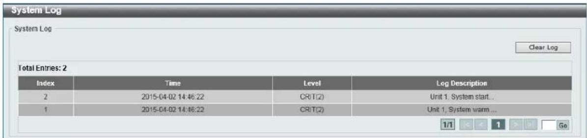
Figure 3-20 System Log Window
Click the Clear Log button to clear the system log entries displayed in the table.
System Attack Log
This window is used to view and clear the system attack log.
To view the following window, click System > System Log > System Attack Log, as shown below:

Figure 3-21 System Attack Log Window
The fields that can be configured are described below:
| Parameter Description | |
| Unit | Select the stacking unit ID of the switch that will be displayed here. |
Click the Clear Attack Log button to clear the system attack log entries displayed in the table.
Time and SNTP
Clock Settings
This window is used to view and configure the time settings for the Switch.
To view the following window, click System > Time and SNTP > Clock Settings, as shown below:

Figure 3-22 Clock Settings Window
The fields that can be configured in Clock Settings are described below:
| Parameter Description | |
| Time | Enter the current time in hours (HH), minutes (MM), and seconds (SS) here. For example, 18:30:30. |
| Date | Enter the current day (DD), month (MM), and year (YY) here. For example, 30/04/2015. |
Click the Apply button to accept the changes made.
Time Zone Settings
This window is used to view and configure time zones and Daylight Savings Time settings for SNTP.
To view the following window, click System > Time and SNTP > Time Zone Settings, as shown below:
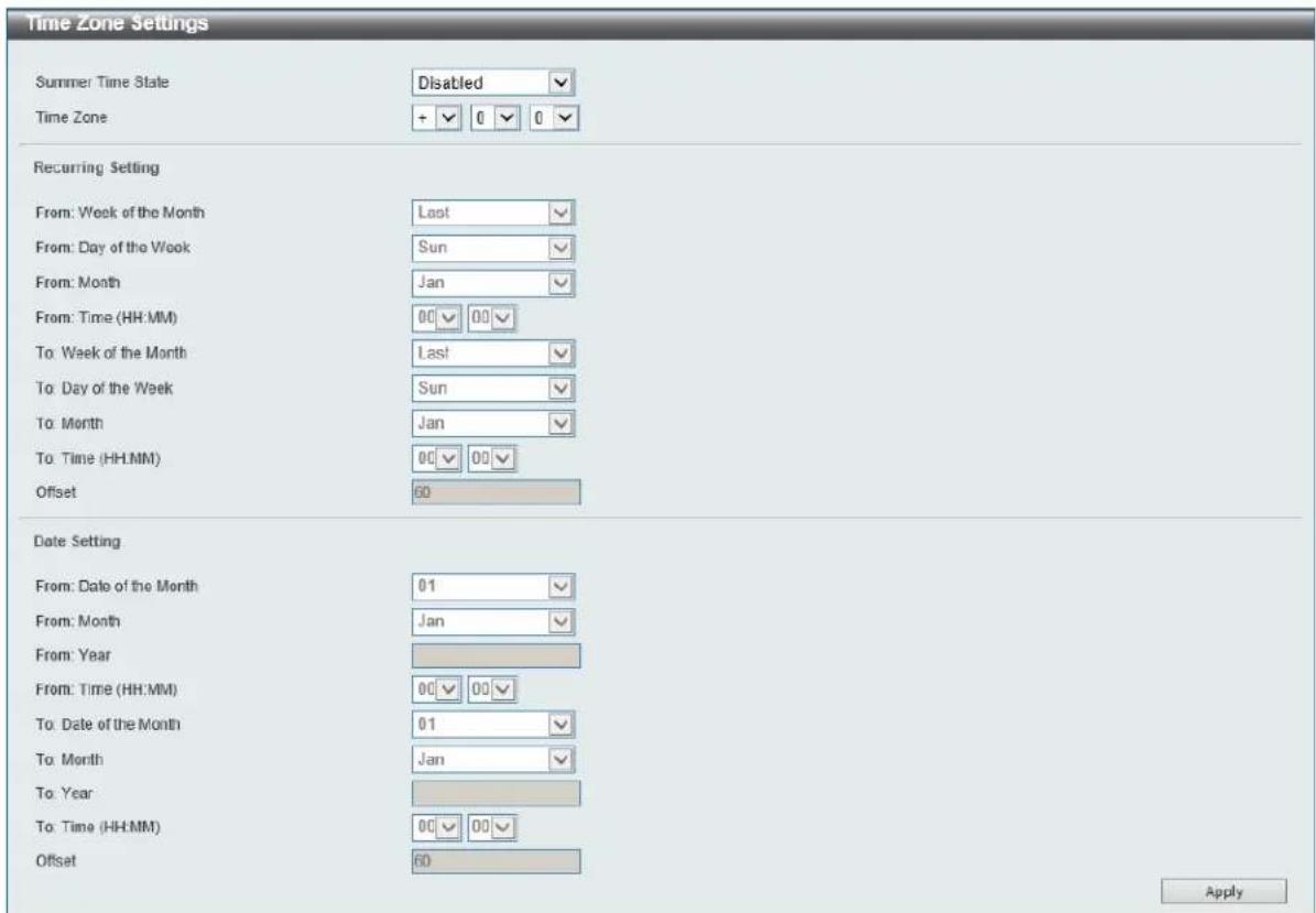
Figure 3-23 Time Zone Settings Window
The fields that can be configured are described below:
| Parameter Description | |
| Summer Time State | Select the summer time setting. Options to choose from are Disabled, Recurring Setting, and Date Setting.·Disabled - Select to disable the summer time setting.·Recurring Setting - Select to configure the summer time that should start and end on the specified week day of the specified month.·Date Setting - Select to configure the summer time that should start and end on the specified date of the specified month. |
| Time Zone | Select to specify your local time zone's offset from Coordinated Universal Time (UTC). |
The fields that can be configured in Recurring Settings are described below:
| Parameter Description | |
| From: Week of the Month | Select week of the month that summer time will start. |
| From: Day of the Week | Select the day of the week that summer time will start. |
| From: Month | Select the month that summer time will start. |
| From: Time | Select the time of the day that summer time will start. |
| To: Week of the Month | Select week of the month that summer time will end. |
| To: Day of the Week | Select the day of the week that summer time will end. |
| To: Month | Select the month that summer time will end. |
| To: Time | Select the time of the day that summer time will end. |
| Offset | Enter the number of minutes to add during summer time. The default value is 60. The range of this offset is 30, 60, 90 and 120. |
The fields that can be configured in Date Settings are described below:
| Parameter Description | |
| From: Date of the Month | Select date of the month that summer time will start. |
| From: Month | Select the month that summer time will start. |
| From: Year | Enter the year that the summer time will start. |
| From: Time | Select the time of the day that summer time will start. |
| To: Date of the Month | Select date of the month that summer time will end. |
| To: Month | Select the month that summer time will end. |
| To: Year | Enter the year that the summer time will end. |
| To: Time | Select the time of the day that summer time will end. |
| Offset | Enter the number of minutes to add during summer time. The default value is 60. The range of this offset is 30, 60, 90 and 120. |
Click the Apply button to accept the changes made.
SNTP Settings
This window is used to view configure the SNTP settings for the switch.
To view the following window, click System > Time and SNTP > SNTP Settings, as shown below:
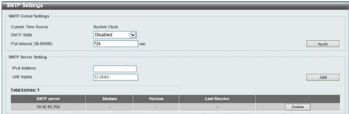
Figure 3-24 SNTP Settings Window
The fields that can be configured in SNTP Global Settings are described below:
| Parameter Description | |
| SNTP State | Select this option to enable or disable SNTP. |
| Poll Interval | Enter the synchronizing interval in seconds. The value is from 30 to99999 seconds. The default interval is 720 seconds. |
Click the Apply button to accept the changes made.
The fields that can be configured in SNTP Server Settings are described below:
| Parameter Description | |
| IPv4 Address | Enter the IP address of the SNTP server which provides the clock synchronization. |
| VRF Name | Enter the name of the VRF instance which the SNTP server belongs to. |
Click the Add button to add the SNTP server.
Click the Delete button to remove the specified entry.
Time Range
This window is used to view and configure the time profile settings.
To view the following window, click System > Time Range, as shown below:
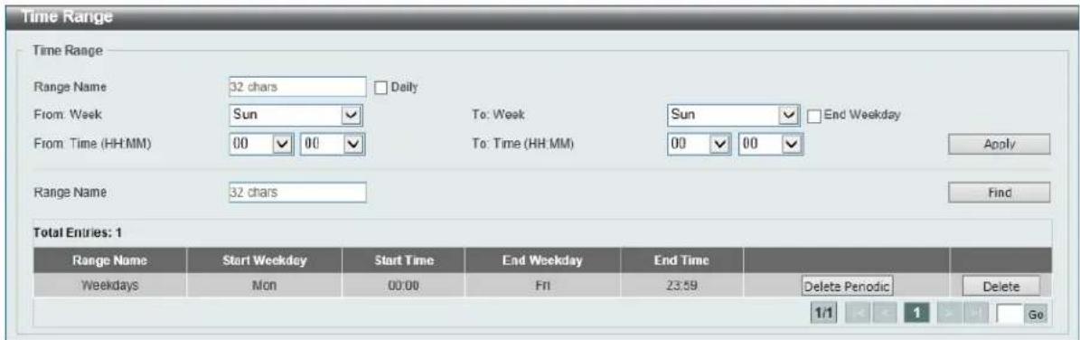
Figure 3-25 Time Range Window
The fields that can be configured are described below:
| Parameter Description | |
| Range Name | Enter the time profile's range name here. This name can be up to 32 characters long. |
| From Week ~ To Week | Select the starting and ending days of the week that will be used for this time profile. Tick theDailyoption to use this time profile for every day of the week. Tick theEnd Week Dayoption to use this time profile from the starting day of the week until the end of the week, which is Sunday. |
| From Time ~ To Time | Select the starting and ending time of the day that will be used for this time profile. The first drop-down menu selects the hour and the second drop-down menu selects the minute. |
Click the Apply button to accept the changes made.
Click the Find button to locate a specific entry based on the information entered.
Click the Delete Periodic button to delete the periodic entry.
Click the Delete button to delete the specified entry.
4. Management
User Account Settings
Password Encryption
Login Method
SNMP
RMON
Telnet/Web
Session Timeout
DHCP
DHCP Auto Configuration
DNS
IP Source Interface
File System
Physical Stacking
Virtual Stacking (SIM)
SMTP Settings
NLB FDB Settings
User Account Settings
On this page, user accounts can be created and configured. Also on this page active user account sessions can be viewed.
There are several configuration options available in the Web User Interface (Web UI). The set of configuration options available to the user depends on the account's Privilege Level.

NOTE: By default, there is no user account created on this switch.
To view the following window, click Management > User Account Settings, as shown below:
After selecting the User Management Settings tab, the following page will appear.
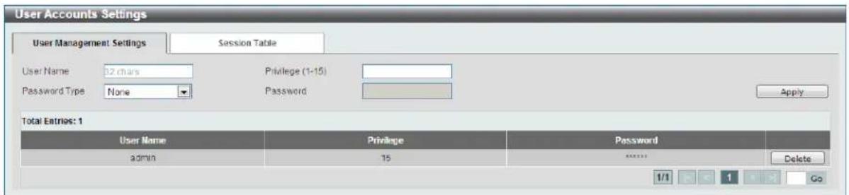
Figure 4-1 User Management Settings Window
The fields that can be configured are described below:
| Parameter Description | |
| User Name | Enter the user account name here. This name can be up to 32 characters long. |
| Privilege | Enter the privilege level for this account here. This value must bebetween 1 and 15. |
| Password Type | Select the password type for this user account here. Options to choose from are None, Plain Text, and Encrypted. |
| Password | After selecting either Plain Text or Encrypted as the password type, enter the password for this user account here. |
Click the Apply button to accept the changes made.
Click the Delete button to delete the specified user account entry.
After selecting the Session Table tab, the following page will appear.

Figure 4-2 Session Table Window
On this page, a list of active user account session will be displayed.
Password Encryption
This window is used to view and configure whether to save the encryption of the password in the configuration file.
To view the following window, click Management > Password Encryption, as shown below:

Figure 4-3 Password Encryption Window
The fields that can be configured in Password Encryption Settings are described below:
| Parameter Description | |
| Password Encryption State | Select this option to enable or disable the encryption of the password before stored in the configuration file. |
Click the Apply button to accept the changes made.
Login Method
This window is used to view and configure the login method for each management interface that this Switch supports.
To view the following window, click Management > Login Method, as shown below:
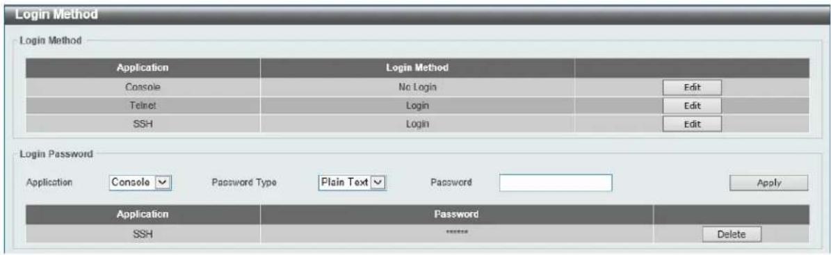
Figure 4-4 Login Method Window
The Login Method section will only be available when Authentication, Authorization, and Accounting (AAA) feature is disabled. The fields that can be configured in Login Method are described below:
| Parameter Description | |
| Login Method | After clicking the Edit button this parameter can be configured. Select the login method for the specified application here. Options to choose from are No Login, Login and Login Local. No Login, as the name implies, requires no login authentication to access the specified application. Login will require the user to at least enter a password when trying to access the application specified. Login Local requires the user to enter a username and a password to access the specified application. |
The fields that can be configured in Login Password are described below:
| Parameter Description | |
| Application | Select the application that will be configured here. Options to choose from are Console, Telnet and SSH. |
| Password Type | Select the password encryption type that will be used here. Options to choose from are Plain Text and Encrypted. |
| Password | Enter the password for the selected application here. This password will be used when the Login Method for the specified application is set as Login. |
Click the Apply button to accept the changes made.
Click the Delete button to remove the password from the specified application.
SNMP
Simple Network Management Protocol (SNMP) is an OSI Layer 7 (Application Layer) designed specifically for managing and monitoring network devices. SNMP enables network management stations to read and modify the settings of gateways, routers, switches, and other network devices. Use SNMP to configure system features for proper operation, monitor performance and detect potential problems in the Switch, switch group or network.
Managed devices that support SNMP include software (referred to as an agent), which runs locally on the device. A defined set of variables (managed objects) is maintained by the SNMP agent and used to manage the device. These objects are defined in a Management Information Base (MIB), which provides
a standard presentation of the information controlled by the on-board SNMP agent. SNMP defines both the format of the MIB specifications and the protocol used to access this information over the network.
The Switch supports the SNMP versions 1, 2c, and 3. The three versions of SNMP vary in the level of security provided between the management station and the network device.
In SNMP v.1 and v.2, user authentication is accomplished using 'community strings', which function like passwords. The remote user SNMP application and the Switch SNMP must use the same community string. SNMP packets from any station that has not been authenticated are ignored (dropped).
The default community strings for the Switch used for SNMP v.1 and v.2 management access are:
• public - Allows authorized management stations to retrieve MIB objects.
- private - Allows authorized management stations to retrieve and modify MIB objects.
SNMPv3 uses a more sophisticated authentication process that is separated into two parts. The first part is to maintain a list of users and their attributes that are allowed to act as SNMP managers. The second part describes what each user on that list can do as an SNMP manager.
The Switch allows groups of users to be listed and configured with a shared set of privileges. The SNMP version may also be set for a listed group of SNMP managers. Thus, you may create a group of SNMP managers that are allowed to view read-only information or receive traps using SNMPv1 while assigning a higher level of security to another group, granting read/write privileges using SNMPv3.
Using SNMPv3 individual users or groups of SNMP managers can be allowed to perform or be restricted from performing specific SNMP management functions. The functions allowed or restricted are defined using the Object Identifier (OID) associated with a specific MIB. An additional layer of security is available for SNMPv3 in that SNMP messages may be encrypted. To read more about how to configure SNMPv3 settings for the Switch read the next section.
Traps
Traps are messages that alert network personnel of events that occur on the Switch. The events can be as serious as a reboot (someone accidentally turned OFF the Switch), or less serious like a port status change. The Switch generates traps and sends them to the trap recipient (or network manager). Typical traps include trap messages for Authentication Failure, Topology Change and Broadcast\Multicast Storm.
MIBs
The Switch in the Management Information Base (MIB) stores management and counter information. The Switch uses the standard MIB-II Management Information Base module. Consequently, values for MIB objects can be retrieved from any SNMP-based network management software. In addition to the standard MIB-II, the Switch also supports its own proprietary enterprise MIB as an extended Management Information Base. Specifying the MIB Object Identifier may also retrieve the proprietary MIB. MIB values can be either read-only or read-write.
The Switch incorporates a flexible SNMP management for the switching environment. SNMP management can be customized to suit the needs of the networks and the preferences of the network administrator. Use the SNMP V3 menus to select the SNMP version used for specific tasks.
The Switch supports the Simple Network Management Protocol (SNMP) versions 1, 2c, and 3. The administrator can specify the SNMP version used to monitor and control the Switch. The three versions of SNMP vary in the level of security provided between the management station and the network device.
SNMP settings are configured using the menus located on the SNMP V3 folder of the Web manager. Workstations on the network that are allowed SNMP privileged access to the Switch can be restricted with the Management Station IP Address menu.
SNMP Global Settings
This window is used to view and configure the SNMP global settings and trap settings.
To view the following window, click Management > SNMP > SNMP Global Settings, as shown below:
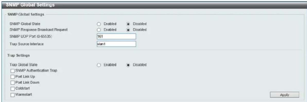
Figure 4-5 SNMP Global Settings Window
The fields that can be configured in SNMP Global Settings are described below:
| Parameter Description | |
| SNMP Global State | Select this option to enable or disable the SNMP feature. |
| SNMP Response Broadcast Request | Select this option to enable or disable the server to response to broadcast SNMP GetRequest packets. |
| SNMP UDP Port | Enter the SNMP UDP port number. |
| Trap Source Interface | Enter the interface whose IP address will be used as the source address for sending the SNMP trap packet. |
The fields that can be configured in Trap Settings are described below:
| Parameter Description | |
| Trap Global State | Select this option to enable or disable the sending of all or specific SNMP notifications. |
| SNMP Authentication Trap | Tick this option to control the sending of SNMP authentication failure notifications. An authenticationFailuretrap is generated when the device receives an SNMP message that is not properly authenticated. The authentication method depends on the version of SNMP being used. For SNMPv1 or SNMPv2c, authentication failure occurs if packets are formed with an incorrect community string. For SNMPv3, authentication failure occurs if packets are formed with an incorrect SHA/MD5 authentication key. |
| Port Link Up | Tick this option to control the sending of port link up notifications. A linkup trap is generated when the device recognizes that one of the communication links has come up. |
| Port Link Down | Tick this option to control the sending of port link down notifications. A linkDown trap is generated when the device recognizes a failure in one of the communication links. |
| Coldstart | Tick this option to control the sending of SNMP coldStart notifications. |
| Warmstart | Tick this option to control the sending of SNMP warmStart notifications. |
Click the Apply button to accept the changes made.
SNMP Linkchange Trap Settings
This window is used to view and configure the SNMP link change trap settings.
To view the following window, click Management > SNMP > SNMP Linkchange Trap Settings, as shown below:
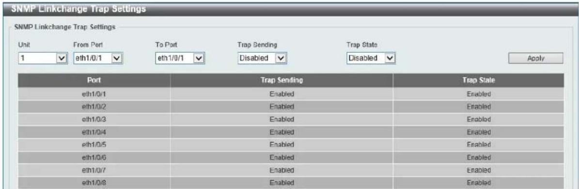
Figure 4-6 SNMP Linkchange Trap Settings Window
The fields that can be configured in SNMP Linkchange Trap Settings are described below:
| Parameter Description | |
| Unit | Select the switch unit that will be used for this configuration here. |
| From Port ~ To Port | Select the appropriate port range used for the configuration here. |
| Trap Sending | Select this option to enable or disable the sending of the SNMP notification traps that is generated by the system. |
| Trap State | Select this option to enable or disable the SNMP link change trap. |
Click the Apply button to accept the changes made.
SNMP View Table Settings
This window is used to assign views to community strings that define which MIB objects can be accessed by a remote SNMP manager. The SNMP Group created with this table maps SNMP users (identified in the SNMP User Table) to the views created in the previous window.
To view the following window, click Management > SNMP > SNMP View Table Settings, as shown below:
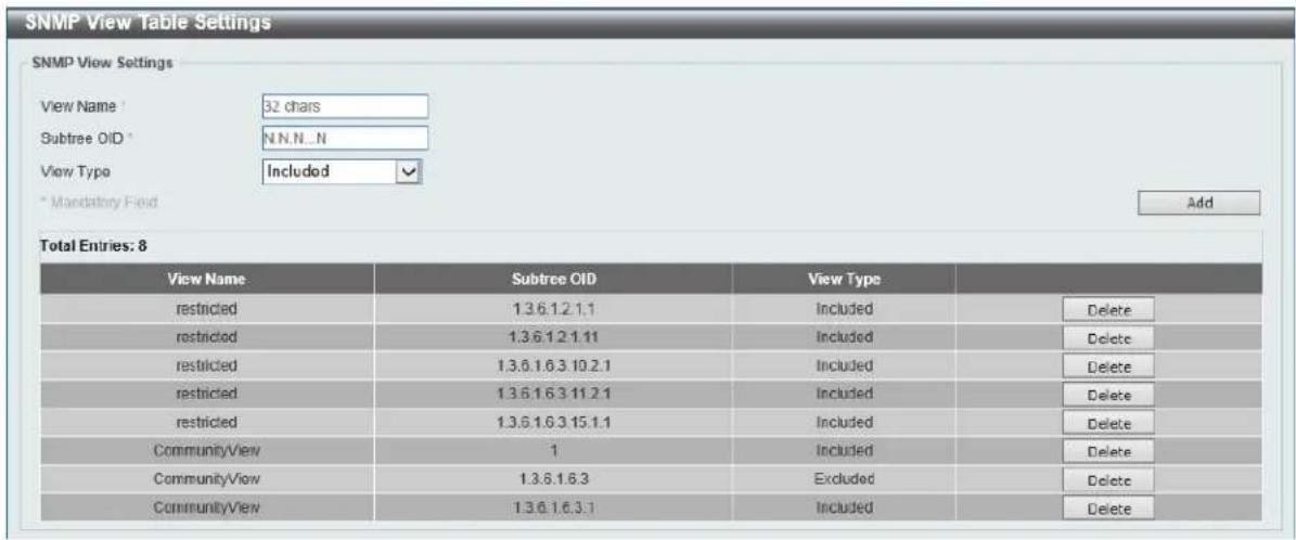
Figure 4-7 SNMP View Table Settings Window
The fields that can be configured in SNMP View Settings are described below:
| Parameter Description | |
| View Name | Type an alphanumeric string of up to 32 characters. This is used to identify the new SNMP view being created. |
| Subtree OID | Type the Object Identifier (OID) sub-tree for the view. The OID identifies an object tree (MIB tree) that will be included or excluded from access by an SNMP manager. |
| View Type | Select the view type here. Options to choose from are Included, and Excluded.Included- Select to include this object in the list of objects that an SNMP manager can access.Excluded- Select to exclude this object from the list of objects that an SNMP manager can access. |
Click the Add button to add a new entry based on the information entered.
Click the Delete button to remove the specified entry.
SNMP Community Table Settings
This window is used to create an SNMP community string to define the relationship between the SNMP manager and an agent. The community string acts like a password to permit access to the agent on the Switch. One or more of the following characteristics can be associated with the community string:
- An Access List of IP addresses of SNMP managers that are permitted to use the community string to gain access to the Switch's SNMP agent.
• Any MIB view that defines the subset of all MIB objects will be accessible to the SNMP community. - Read/write or read-only level permission for the MIB objects accessible to the SNMP community.
To view the following window, click Management > SNMP > SNMP Community Table Settings, as shown below:
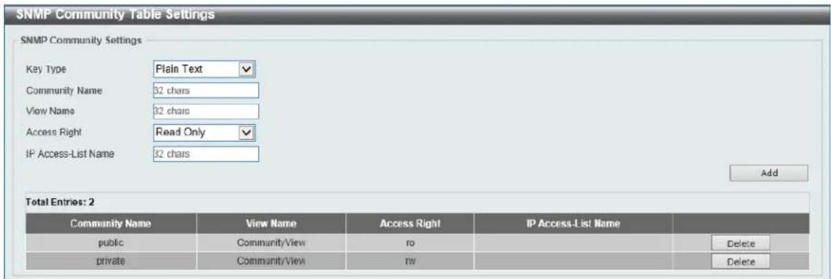
Figure 4-8 SNMP Community Table Settings Window
The fields that can be configured in SNMP Community Settings are described below:
| Parameter Description | |
| Key Type | Select the key type for the SNMP community. Options to choose from are Plain Text, and Encrypted. |
| Community Name | Enter an alphanumeric string of up to 32 characters that is used to identify members of an SNMP community. This string is used like a password to give remote SNMP managers access to MIB objects in the Switch's SNMP agent. |
| View Name | Enter an alphanumeric string of up to 32 characters that is used to identify the group of MIB objects that a remote SNMP manager is allowed to access on the Switch. The view name must exist in the SNMP View Table. |
| Access Right | Select the access right here. Options to choose from are Read Only, and Read Write.Read Only - SNMP community members using the community string created can only read the contents of the MIBs on the Switch.Read Write - SNMP community members using the community string created can read from, and write to the contents of the MIBs on the Switch. |
| IP Access-List Name | Enter the name of the standard access list to control the user to use this community string to access to the SNMP agent. |
Click the Add button to add a new entry based on the information entered.
Click the Delete button to remove the specified entry.
SNMP Group Table Settings
An SNMP Group created with this table maps SNMP users (identified in the SNMP User Table) to the views created in the previous window.
To view the following window, click Management > SNMP > SNMP Group Table Settings, as shown below:
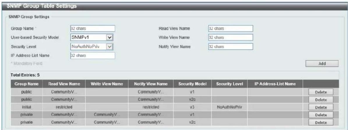
Figure 4-9 SNMP Group Table Settings Window
The fields that can be configured in SNMP Group Settings are described below:
| Parameter Description | |
| Group Name | Enter the group name of a maximum of 32 characters. The syntax is general string that does not allow space. |
| Read View Name | Enter the read view name that the group user can access. |
| User-based Security Model | Select the security model here. Options to choose from are SNMPv1, SNMPv2c, and SNMPv3.SNMPv1 - Select to allow the group user to use the SNMPv1 security model.SNMPv2c - Select to allow the group user to use the SNMPv2c security model.SNMPv3 - Select to allow the group user to use the SNMPv3 security model. |
| Write View Name | Enter the write view name that the group user can access. |
| Security Level | When selecting SNMPv3 in the User-based Security Model drop-down list, this option is available.NoAuthNoPriv - Specify that there will be no authorization and no encryption of packets sent between the Switch and a remote SNMP manager.AuthNoPriv - Specify that authorization will be required, but there will be no encryption of packets sent between the Switch and a remote SNMP manager.AuthPriv - Specify that authorization will be required, and that packets sent between the Switch and a remote SNMP manger will be encrypted. |
| Notify View Name | Enter a write view name that the group user can access. The notify view describes the object that can be reported its status via trap packets to the group user. |
| IP Address-List Name | Enter the standard IP access control list (ACL) to associate with the group. |
Click the Add button to add a new entry based on the information entered.
Click the Delete button to remove the specified entry.
SNMP Engine ID Local Settings
The Engine ID is a unique identifier used for SNMP V3 implementations on the Switch.
To view the following window, click Management > SNMP > SNMP Engine ID Local Settings, as shown below:

Figure 4-10 SNMP Engine ID Local Settings Window
The fields that can be configured in SNMP Engine ID Local Settings are described below:
| Parameter Description | |
| Engine ID | Enter the engine ID string with the maximum of 24 characters. |
Click the Default button to revert the engine ID to the default.
Click the Apply button to accept the changes made.
SNMP User Table Settings
This window is used to configure and display the SNMP users that are currently configured on the Switch. To view the following window, click Management > SNMP > SNMP User Table Settings, as shown below:
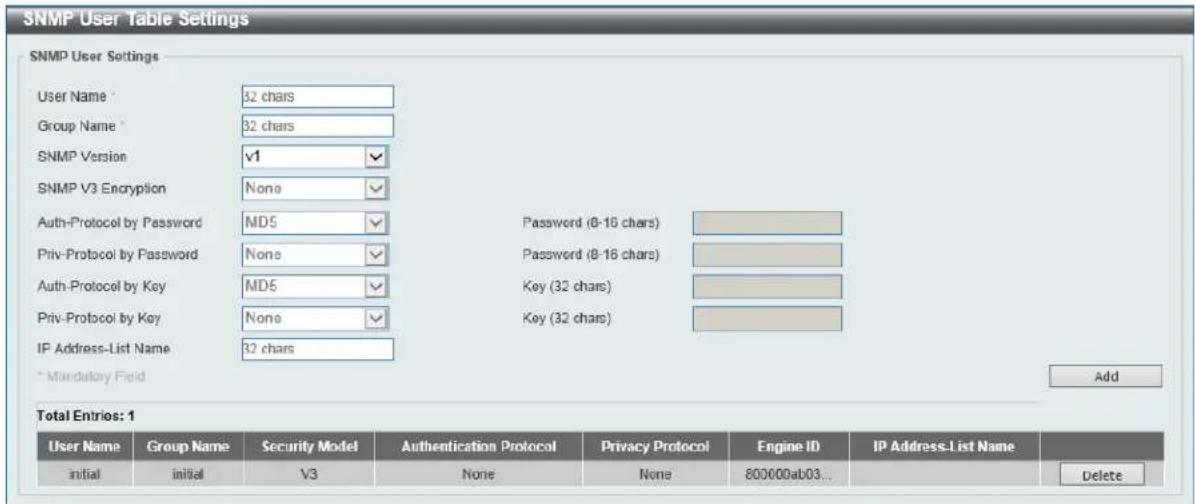
Figure 4-11 SNMP User Table Settings Window
The fields that can be configured in SNMP User Settings are described below:
| Parameter Description | |
| User Name | Enter an alphanumeric string of up to 32 characters. This is used to identify the SNMP users. |
| Group Name | Enter the SNMP group name to which the user belongs. The syntax is general string that does not allow spaces. |
| SNMP Version | Select the SNMP version. Options to choose from are v1, v2c, and v3. |
| SNMP V3 Encryption | When selecting v3 in the SNMP Version drop-down list, this option is available. Options to choose from are None, Password, and Key. |
| Auth-Protocol by Password | When selecting v3 in the SNMP Version drop-down list, and selecting Password in the SNMP V3 Encryption drop-down list, this option is available. Select the authentication level. Options to choose from are the following:MD5 - Select to use the HMAC-MD5-96 authentication level. This field will require the user to enter a password or a key.SHA - Specify that the HMAC-SHA authentication protocol will be used. This field will require the user to enter a password or a key. |
| Password | Enter the authentication protocol password here. For MD5 this password must be between 8 and 16 characters long. For SHA this password must be between 8 and 20 characters long. |
| Priv-Protocol by Password | When selecting v3 in the SNMP Version drop-down list, and selecting Password in the SNMP V3 Encryption drop-down list, this option is available. Select the private protocol. Options to choose from are the following:None - Specify that no authorization protocol is in use.DES56 - Specify that DES 56-bit encryption is in use, based on the CBC-DES (DES-56) standard. This field will require the user to enter a password or a key. |
| Password | Enter the private protocol password here. For none, this field will be disabled. For DES56 this password must be between 8 and 16 characters long. |
| Auth-Protocol by Key | When selecting v3 in the SNMP Version drop-down list, and selecting Key in the SNMP V3 Encryption drop-down list, this option is available. Select the authentication level. Options to choose from are the following:MD5 - Select to use the HMAC-MD5-96 authentication level. This field will require the user to enter a password or a key.SHA - Specify that the HMAC-SHA authentication protocol will be used. This field will require the user to enter a password or a key. |
| Key | Enter the authentication protocol key here. For MD5 this key must be 32 characters long. For SHA this key must be 40 characters long. |
| Priv-Protocol by Key | When selecting v3 in the SNMP Version drop-down list, and selecting Key in the SNMP V3 Encryption drop-down list, this option is available. Select the private protocol. Options to choose from are the following:None - Specify that no authorization protocol is in use.DES56 - Specify that DES 56-bit encryption is in use, based on the CBC-DES (DES-56) standard. This field will require the user to enter a password or a key. |
| Key | Enter the private protocol key here. For none, this field will be disabled. For DES56 this key must be 32 characters long. |
| IP Address-List Name | Enter the standard IP access control list (ACL) to associate with the user. |
Click the Add button to add a new entry based on the information entered.
Click the Delete button to remove the specified entry.
SNMP Host Table Settings
This window is used to view and configure the recipient of the SNMP notification.
To view the following window, click Management > SNMP > SNMP Host Table Settings, as shown below:
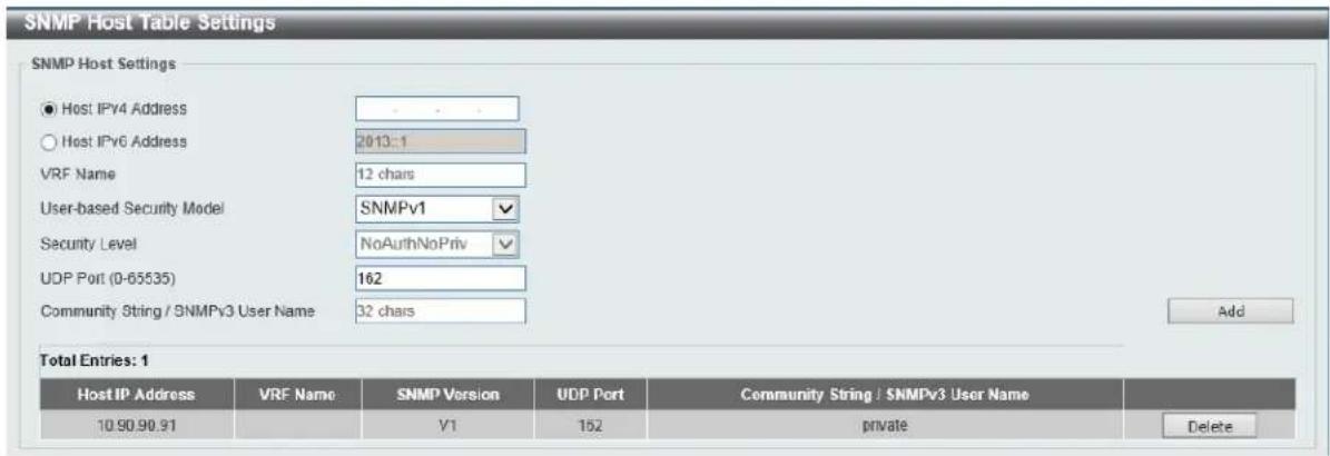
Figure 4-12 SNMP Host Table Settings Window
The fields that can be configured in SNMP Host Settings are described below:
| Parameter Description | |
| Host IPv6 Address | Enter the IPv4 address of the SNMP notification host. |
| Host IPv6 Address | Enter the IPv6 address of the SNMP notification host. |
| VRF Name | Enter the VRF instance's name that will be used in this configuration here. This name can be up to 12 characters long. |
| User-based Security Model | Select the security model here. Options to choose from areSNMPv1, SNMPv2c, and SNMPv3.SNMPv1 - Select to allow the group user to use the SNMPv1 security model.SNMPv2c - Select to allow the group user to use the SNMPv2c security model.SNMPv3 - Select to allow the group user to use the SNMPv3 security model. |
| Security Level | When selectingSNMPv3in the User-based Security Model drop-down list, this option is available.NoAuthNoPriv - Specify that there will be no authorization and no encryption of packets sent between the Switch and a remote SNMP manager.AuthNoPriv - Specify that authorization will be required, but there will be no encryption of packets sent between the Switch and a remote SNMP manager.AuthPriv - Specify that authorization will be required, and that packets sent between the Switch and a remote SNMP manger will be encrypted. |
| UDP Port | Enter the UDP port number. The default trap UDP port number is 162. The range of UDP port numbers is from 0 to 65535. Some port numbers may conflict with other protocols. |
| Community String / SNMPv3User Name | Enter the community string to be sent with the notification packet. |
Click the Add button to add a new entry based on the information entered.
Click the Delete button to remove the specified entry.
RMON
RMON Global Settings
This window is used to enable or disable remote monitoring (RMON) for the rising and falling alarm trap feature for the SNMP function on the Switch.
To view the following window, click Management > RMON > RMON Global Settings, as shown below:

Figure 4-13 RMON Global Settings Window
The fields that can be configured in RMON Global Settings are described below:
| Parameter Description | |
| RMON Rising Alarm Trap | Select this option to enable or disable the RMON Rising Alarm Trap Feature. |
| RMON Falling Alarm Trap | Select this option to enable or disable the RMON Falling Alarm Trap Feature. |
Click the Apply button to accept the changes made.
RMON Statistics Settings
This window is used to configure and display the RMON statistics on the specified port.
To view the following window, click Management > RMON > RMON Statistics Settings, as shown below:
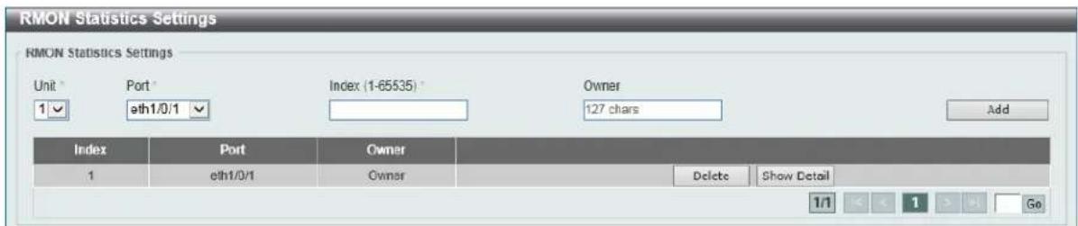
Figure 4-14 RMON Statistics Settings Window
The fields that can be configured in RMON Statistics Settings are described below:
| Parameter Description | |
| Unit | Select the switch unit that will be used for this configuration here. |
| Port | Select to choose the port. |
| Index | Enter the RMON table index. The value is from 1 to 65535 |
| Owner | Enter the owner string. The string can be up to 127 characters. |
Click the Add button to add a new entry based on the information entered.
Click the Delete button to remove the specified entry.
Click the Show Detail button to see the detail information of the specific port.
Enter a page number and click the Go button to navigate to a specific page when multiple pages exist.
After clicking the Show Detail button, the following window will appear.
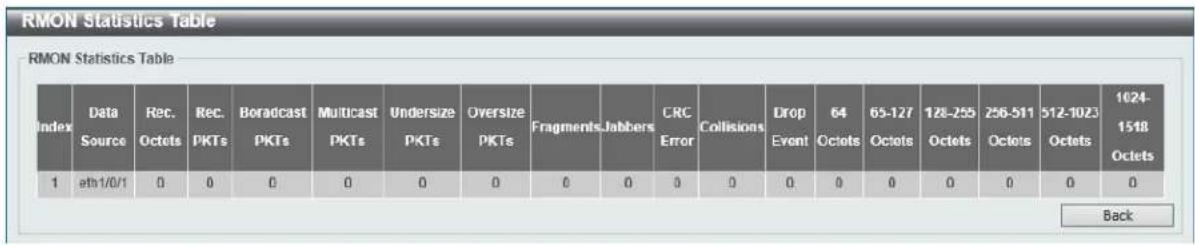
Figure 4-15 RMON Statistics Settings (Show Detail) Window
Click the Back button to return to the previous window.
RMON History Settings
This window is used to view and configure RMON MIB history statistics gathered on the specified port.
To view the following window, click Management > RMON > RMON History Settings, as shown below:
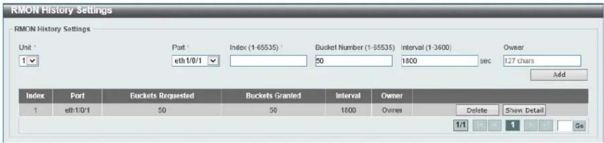
Figure 4-16 RMON History Settings Window
The fields that can be configured in RMON History Settings are described below:
| Parameter Description | |
| Unit | Select the switch unit that will be used for this configuration here. |
| Port | Select the port that will be used here. |
| Index | Enter the history group table index. The value is from 1 to 65535 |
| Bucket Number | Enter Specifies the number of buckets specified for the RMON collection history group of statistics. The range is from 1 to 65535. The default value is 50. |
| Interval | Enter the time in seconds in each polling cycle. The range is from 1 to 3600. |
| Owner | Enter the owner string. The string can be up to 127 characters. |
Click the Add button to add a new entry based on the information entered.
Click the Delete button to remove the specified entry.
Click the Show Detail button to see the detail information of the specific port.
Enter a page number and click the Go button to navigate to a specific page when multiple pages exist.
After clicking the Show Detail button, the following window will appear.

Figure 4-17 RMON History Settings (Show Detail) Window
Click the Back button to return to the previous window.
RMON Alarm Settings
This window is used to view and configure alarm entries to monitor an interface.
To view the following window, click Management > RMON > RMON Alarm Settings, as shown below:
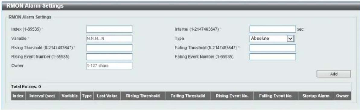
Figure 4-18 RMON Alarm Settings Window
The fields that can be configured in RMON Alarm Settings are described below:
| Parameter Description | |
| Index | Enter the alarm index. The range is from 1 to 65535. |
| Interval | Enter the interval in seconds for the sampling of the variable and checking against the threshold. The valid range is from 1 to 2147483648 seconds. |
| Variable | Enter the object identifier of the variable to be sampled. |
| Type | Select the monitoring type. Options to choose from are Absolute and Delta. |
| Rising Threshold | Enter the rising threshold value between 0 and 2147483647. |
| Falling Threshold | Enter the falling threshold value between 0 and 2147483647. |
| Rising Event Number | Enter the index of the event entry that is used to notify the rising threshold crossing event. The valid range is from 1 to 65535. If not specified, no action is taken while crossing the ringing threshold. |
| Falling Event Number | Enter the index of the event entry that is used to notify the falling threshold crossing event. The valid range is from 1 to 65535. If not specified, no action is taken while crossing the falling threshold. |
| Owner | Enter the owner string up to 127 characters. |
Click the Add button to add a new entry based on the information entered.
Click the Delete button to remove the specified entry.
Enter a page number and click the Go button to navigate to a specific page when multiple pages exist.
RMON Event Settings
This window is used to view and configure event entries.
To view the following window, click Management > RMON > RMON Event Settings, as shown below:
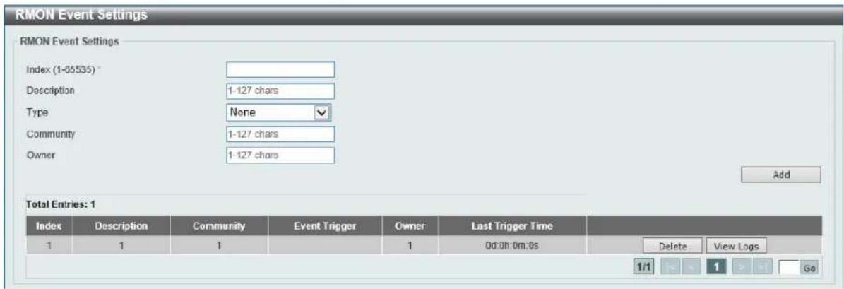
Figure 4-19 RMON Event Settings Window
The fields that can be configured in RMON Event Settings are described below:
| Parameter Description | |
| Index | Enter the index of the alarm entry between 1 and 65535. |
| Description | Enter a description for the RMON event entry. The string is up to 127 characters long. |
| Type | Select the RMON event entry type. Options to choose from are None, Log, Trap, and Log and Trap. |
| Community | Enter the community string. The string can be up to 127 characters. |
| Owner | Enter the owner string. The string can be up to 127 characters. |
Click the Add button to add a new entry based on the information entered.
Click the Delete button to remove the specified entry.
Click the View Logs button to see the detail information of the specific port.
Enter a page number and click the Go button to navigate to a specific page when multiple pages exist.
After clicking the View Logs button, the following window will appear.

Figure 4-20 RMON Event Settings (View Logs) Window
Click the Back button to return to the previous window.
Telnet/Web
This window is used to view and configure Telnet and Web settings on the switch.
To view the following window, click Management > Telnet/Web, as shown below:
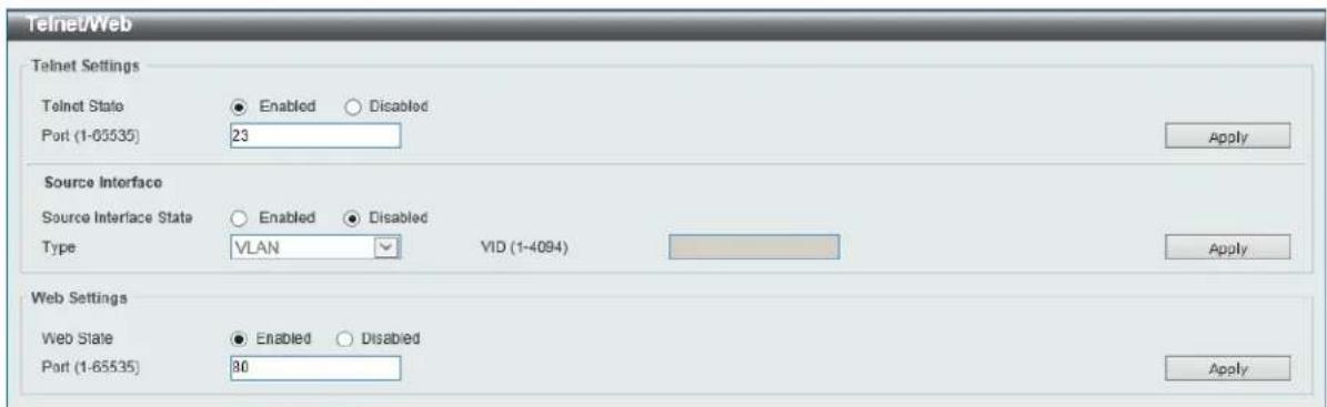
Figure 4-21 Telnet/Web Window
The fields that can be configured in Telnet Settings are described below:
| Parameter Description | |
| Telnet State | Select this option to enable or disable the configuration through Telnet. |
| Port | Enter the TCP port number used for Telnet management of the Switch.The “well-known” TCP port for the Telnet protocol is 23. |
Click the Apply button to accept the changes made.
The fields that can be configured in Source Interface are described below:
| Parameter Description | |
| Source Interface State | Select to enable or disable the source interface's state here. |
| Type | Select the type of source interface that will be used here. Options to choose from are Loopback, Mgmt, and VLAN. |
| VID | Enter the interface's ID here. For loopback interfaces the range is from 1 to 8. For the management (Mgmt) interface this value can only be 0. For VLAN interfaces the range is from 1 to 4094. |
Click the Apply button to accept the changes made.
The fields that can be configured in Web Settings are described below:
| Parameter Description | |
| Web State | Select this option to enable or disable the configuration through the web. |
| Port | Enter the TCP port number used for Telnet management of the Switch. The “well-known” TCP port for the Telnet protocol is 80. |
Click the Apply button to accept the changes made.
Session Timeout
This window is used to view and configure the session timeout settings.
To view the following window, click Management > Session Timeout, as shown below:

Figure 4-22 Session Timeout Window
The fields that can be configured in Session Timeout are described below:
| Parameter Description | |
| Web Session Timeout | Enter the time in seconds of the web session timeout. Tick the Default check box to return to the default setting. The value is from 60 to 36000 seconds. The default value is 180 seconds. |
| Console Session Timeout | Enter the time in minutes of the web session timeout. Tick the Default check box to return to the default setting. The value is from 0 to 1439 minutes. 0 means never timeout. The default value is 3 minutes. |
| Telnet Session Timeout | Enter the time in minutes of the Telnet session timeout. Tick the Default check box to return to the default setting. The value is from 0 to 1439 minutes. 0 means never timeout. The default value is 3 minutes. |
| SSH Session Timeout | Enter the time in minutes of the SSH session timeout. Tick the Default check box to return to the default setting. The value is from 0 to 1439 minutes. 0 means never timeout. The default value is 3 minutes. |
Click the Apply button to accept the changes made.
DHCP
Service DHCP
This window is used to view and configure the DHCP relay service on the switch.
To view the following window, click Management > DHCP > Service DHCP, as shown below:

Figure 4-23 Service DHCP Window
The fields that can be configured in Service DHCP are described below:
| Parameter Description | |
| Service DHCP State | Select this option to enable or disable the DHCP relay service. |
Click the Apply button to accept the changes made.
The fields that can be configured in Service IPv6 DHCP are described below:
| Parameter Description | |
| Service IPv6 DHCP State | Select this option to enable or disable the IPv6 DHCP relay service. |
Click the Apply button to accept the changes made.
DHCP Class Settings
This window is used to view and configure the DHCP class and the DHCP option matching pattern for the DCHP class.
To view the following window, click Management > DHCP > DHCP Class Settings, as shown below:
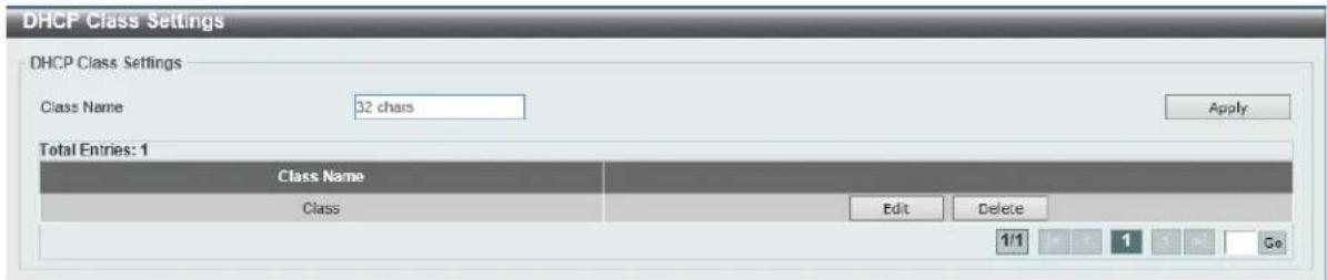
Figure 4-24 DHCP Class Settings Window
The fields that can be configured in DHCP Class Settings are described below:
| Parameter Description | |
| Class Name | Enter the DHCP class name with a maximum of 32 characters. |
Click the Apply button to accept the changes made.
Click the Edit button to modify the DHCP option matching pattern for the corresponding DCHP class.
Click the Delete button to remove the specified entry.
Enter a page number and click the Go button to navigate to a specific page when multiple pages exist.
After clicking the Edit button, the following window will appear.
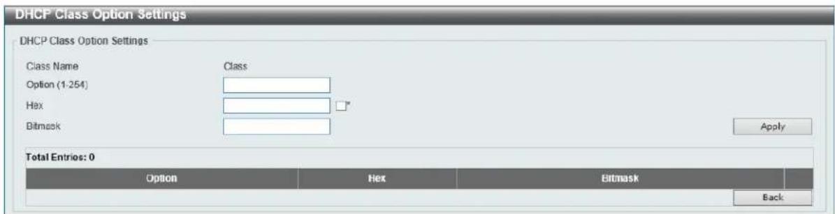
Figure 4-25 DHCP Class Settings (Edit) Window
The fields that can be configured in DHCP Class Option Settings are described below:
| Parameter Description | |
| Option | Enter the DHCP option number. The range is from 1 to 255. |
| Hex | Enter the hex pattern of the specified DHCP option. Tick the * check box not to match the remaining bits of the option. |
| Bitmask | Enter the hex bit mask for masking of the pattern. The masked pattern bits will be matched. If not specified, all bits entered in Hex will be checked. |
Click the Apply button to accept the changes made.
Click the Delete button to remove the specified entry.
Click the Back button to return to the previous window.
DHCP Server
DHCP, or Dynamic Host Configuration Protocol, allows the switch to delegate IP addresses, subnet masks, default gateways and other IP parameters to devices that request this information. This occurs when a DHCP enabled device is booted on or attached to the locally attached network. This device is known as the DHCP client and when enabled, it will emit query messages on the network before any IP parameters are set. When the DHCP server receives this request, it returns a response to the client, containing the previously mentioned IP information that the DHCP client then utilizes and sets on its local configurations.
The user can configure many DHCP related parameters that it will utilize on its locally attached network, to control and limit the IP settings of clients desiring an automatic IP configuration, such as the lease time of the allotted IP address, the range of IP addresses that will be allowed in its DHCP pool, the ability to exclude various IP addresses within the pool so as not to make identical entries on its network, or to assign the IP address of an important device (such as a DNS server or the IP address of the default route) to another device on the network.
Users also have the ability to bind IP addresses within the DHCP pool to specific MAC addresses in order to keep consistent the IP addresses of devices that may be important to the upkeep of the network that require a static IP address.
DHCP Server Global Settings
This window is used to view and configure the DHCP server global parameters.
To view the following window, click Management > DHCP > DHCP Server > DHCP Server Global Settings, as shown below:

Figure 4-26 DHCP Server Global Settings Window
The fields that can be configured in DHCP Use Class State are described below:
| Parameter Description | |
| DHCP Use Class State | Select to enable or disable the feature where the DHCP server uses a class. |
Click the Apply button to accept the changes made.
The fields that can be configured in DHCP Server Settings are described below:
| Parameter Description | |
| DHCP Ping Packet | Enter the number of ping packets that the switch will send out on the network containing the IP address to be allotted. If the ping request is not returned, the IP address is considered unique to the local network and then allotted to the requesting client. 0 means there is no ping test. The range is from 0 to 10. The default value is 2. |
| DHCP Ping Timeout | Enter the amount of time the DHCP server must waits before timing out a ping packet. The range is from 100 to 10000 milliseconds. The default value is 100 milliseconds. |
Click the Apply button to accept the changes made.
DHCP Server Pool Settings
This window is used to view and configure the DHCP server pool settings.
To view the following window, click Management > DHCP > DHCP Server > DHCP Server Pool Settings, as shown below:
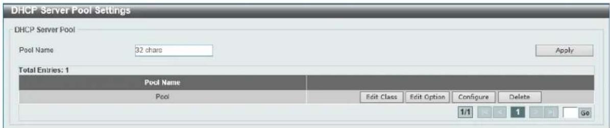
Figure 4-27 DHCP Server Pool Settings Window
The fields that can be configured in DHCP Server Pool are described below:
| Parameter Description | |
| Pool Name | Enter the DHCP server's pool name here. This name can be up to 32 characters long. |
Click the Apply button to accept the changes made.
Click the Edit Class button to configure the DHCP class.
Click the Edit Option button to configure the DHCP server pool's option settings.
Click the Configure button to configure the DHCP server pool's settings.
Click the Delete button to remove the specified entry.
After clicking the Edit Class button, the following page will appear.
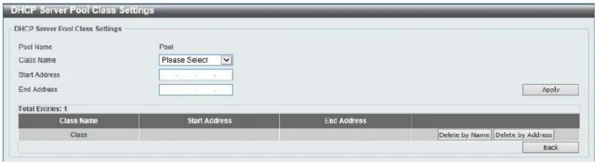
Figure 4-28 DHCP Server Pool Settings (Edit Class) Window
The fields that can be configured in DHCP Server Pool Class Settings are described below:
| Parameter Description | |
| Class Name | Select an existing DHCP class' name here that will be associated with this DHCP pool. |
| Start Address | Enter the starting IPv4 address that will be associated with the DHCP class in the DHCP pool here. |
| End Address | Enter the ending IPv4 address that will be associated with the DHCP class in the DHCP pool here. |
Click the Apply button to accept the changes made.
Click the Delete by Name button to remove the DHCP class association by name.
Click the Delete by Address button to remove the DHCP class association by address.
After clicking the Edit Option button, the following page will appear.
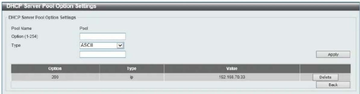
Figure 4-29 DHCP Server Pool Settings (Edit Option) Window
The fields that can be configured in DHCP Server Pool Option Settings are described below:
| Parameter Description | |
| Option | Enter the DHCP option number here. The range is from 1 to 254. |
| Type | Select the DHCP option type here. Options to choose from are ASCII, HEX, and IP. After selecting ASCII, enter the ASCII string in the space provided. This string can be up to 255 characters long. After selecting HEX, enter the hexadecimal string in the space provided. This string can be up to 254 characters long. Select the None option to specify to use a zero-length hexadecimal string. After selecting IP, enter the IPv4 address(es) in the space(s) provided. Up to 8 IPv4 address can be entered. |
Click the Apply button to accept the changes made.
Click the Delete button to remove the specified entry.
Click the Back button to return to the previous window.
After clicking the Configure button, the following page will appear.
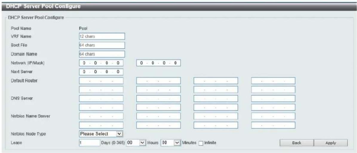
Figure 4-30 DHCP Server Pool Settings (Configure) Window
The fields that can be configured in DHCP Server Pool Configure are described below:
| Parameter Description | |
| VRF Name | Enter the VRF instance's name that will be used in this configuration here. This name can be up to 12 characters long. |
| Boot File | Enter the boot file's name here. This name can be up to 64 characters long. |
| Domain Name | Enter the domain name for the DHCP client here. This name can be up to 64 characters long. |
| Network (IP/Mask) | Enter the network IPv4 address and subnet mask for the DHCP client here. |
| Next Server | Enter the next server's IPv4 address here. This parameter is used to specify the server IP address for the client to boot the image. The server is typically a TFTP server. Only one boot server can be specified. |
| Default Router | Enter the IPv4 address of the default router for the DHCP client here. Up to 8 IPv4 address can be entered here. The IP address of the router should be on the same subnet as the client's subnet. Routers are listed in the order of preference. If default routers are already configured, the default routers configured later will be added to the default interface list. |
| DNS Server | Enter the IPv4 address to be used by the DHCP client as the DNS server here. Up to 8 IPv4 address can be entered here. Servers are listed in the order of preference. If DNS servers are already configured, the DNS servers configured later will be added to the DNS server list. |
| Netbios Name Server | Enter the WINS name server's IPv4 address for the DHCP client here. Up to 8 IPv4 address can be entered here. Servers are listed in the order of preference. If name servers are already configured, the name |
| server configured later will be added to the default interface list. | |
| Netbios Node Type | Select the NetBIOS node type for Microsoft DHCP clients here. Options to choose from are Broadcast, Peer To Peer, Mixed, and Hybrid. The node type of the h-node (Hybrid) is recommended. The node type determines the method NetBIOS use to register and resolve names. The broadcast system uses broadcasts. A p-node system uses only point-to-point name queries to a name server (WINS). An m-node system broadcasts first, and then queries the name server. A hybrid system queries the name server first, and then broadcasts. |
| Lease | Enter and select the lease time for an IPv4 address that is assigned from the address pool here. Enter the Days in the range from 0 to 365. Select the Hours and Minutes from the drop-down menus. Alternatively, the Infinite option can be selected to specify that the lease time is unlimited. |
Click the Apply button to accept the changes made.
Click the Back button to return to the previous window.
DHCP Server Exclude Address
This window is used to view and exclude a range of IPv4 addresses from being allocated to the DHCP client. The DHCP server automatically allocates addresses in DHCP address pools to DHCP clients. All the addresses except the interface's IP address on the router and the excluded address(es) specified here are available for allocation. Multiple ranges of addresses can be excluded. To remove a range of excluded addresses, administrators must specify the exact range of addresses previously configured.
To view the following window, click Management > DHCP > DHCP Server > DHCP Server Exclude Address, as shown below:
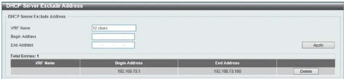
Figure 4-31 DHCP Server Exclude Address Window
The fields that can be configured in DHCP Server Exclude Address are described below:
| Parameter Description | |
| VRF Name | Enter the VRF instance's name that will be used in this configuration here. This name can be up to 12 characters long. |
| Begin Address | Enter the first IPv4 address of a range of addresses to be excluded here. |
| End Address | Enter the last IPv4 address of a range of addresses to be excluded here. |
Click the Apply button to accept the changes made.
Click the Delete button to remove the specified entry.
DHCP Server Manual Binding
This window is used to view and configure the DHCP server feature's manual binding settings. With a manual binding entry, the IP address can be either be bound with a client-identifier or bound with the hardware address of the host.
To view the following window, click Management > DHCP > DHCP Server > DHCP Server Manual Binding, as shown below:
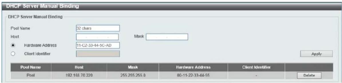
Figure 4-32 DHCP Server Manual Binding Window
The fields that can be configured in DHCP Server Manual Binding are described below:
| Parameter Description | |
| Pool Name | Enter the DHCP server's pool name here. This name can be up to 32 characters long. |
| Host | Enter the DHCP host's IPv4 address here. |
| Mask | Enter the DHCP host's network subnet mask here. |
| Hardware Address | Enter the DHCP host's MAC address here. |
| Client Identifier | Enter the DHCP host's identifier in hexadecimal notation here. The client identifier is formatted by the media type and the MAC address. |
Click the Apply button to accept the changes made.
Click the Delete button to remove the specified entry.
DHCP Server Dynamic Binding
This window is used to view and clear the DHCP server's dynamic binding entries.
To view the following window, click Management > DHCP > DHCP Server > DHCP Server Dynamic Binding, as shown below:
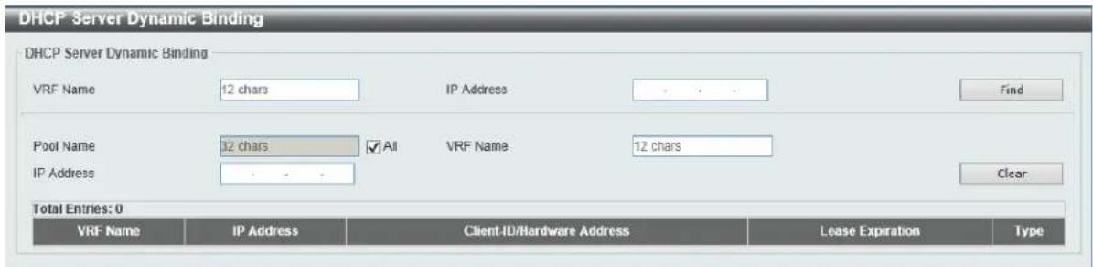
Figure 4-33 DHCP Server Dynamic Binding Window
The fields that can be configured in DHCP Server Dynamic Binding are described below:
| Parameter Description | |
| VRF Name | Enter the VRF instance's name that will be used here. This name can be up to 12 characters long. |
| IP Address | Enter the binding entry's IPv4 address here. |
| Pool Name | Enter the DHCP server's pool name here. This name can be up to 32 characters long. Select the All option to clear the binding entries for all pools. |
Click the Find button to locate a specific entry based on the information entered.
Click the Clear button to clear the entries based on the information specified.
DHCP Server IP Conflict
This window is used to view and clear the DHCP conflict entries from the DHCP server database.
To view the following window, click Management > DHCP > DHCP Server > DHCP Server IP Conflict, as shown below:
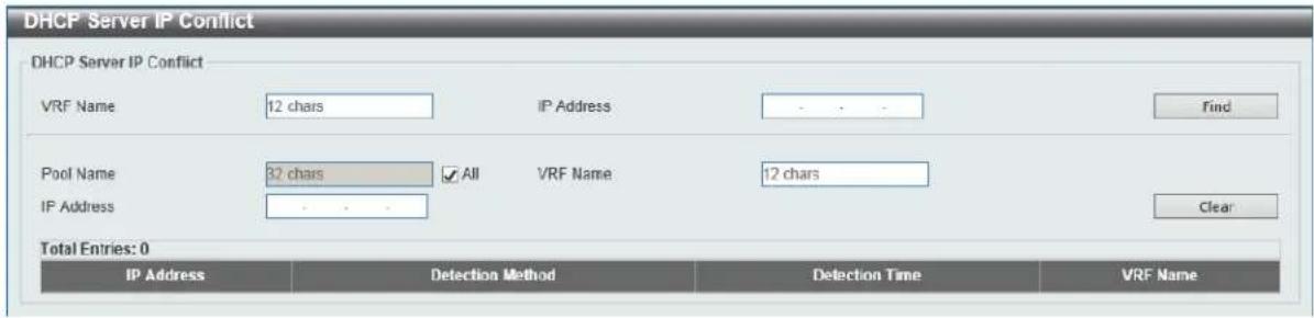
Figure 4-34 DHCP Server IP Conflict Window
The fields that can be configured in DHCP Server IP Conflict are described below:
| Parameter Description | |
| VRF Name | Enter the VRF instance's name that will be used here. This name can be up to 12 characters long. |
| IP Address | Enter the IPv4 address of the conflict entry to be located or cleared. |
| Pool Name | Enter the DHCP server's pool name here. This name can be up to 32 characters long. Select the All option to clear the conflict entries for all pools. |
Click the Find button to locate a specific entry based on the information entered.
Click the Clear button to clear the entries based on the information specified.
DHCP Server Statistic
This window is used to display DHCP server statistics.
To view the following window, click Management > DHCP > DHCP Server > DHCP Server Statistic, as shown below:
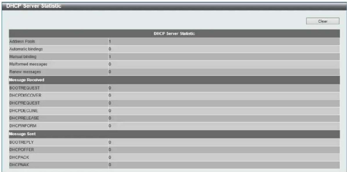
Figure 4-35 DHCP Server Statistic Window
Click the Clear button to clear the statistics information displayed here.
DHCPv6 Server
DHCPv6 Server Pool Settings
This window is used to view and configure the DHCPv6 server pool settings.
To view the following window, click Management > DHCP > DHCPv6 Server > DHCPv6 Server Pool Settings, as shown below:
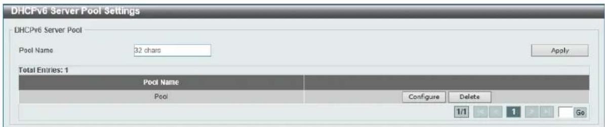
Figure 4-36 DHCPv6 Server Pool Settings Window
The fields that can be configured in DHCPv6 Server Pool are described below:
| Parameter Description | |
| Pool Name | Enter the DHCPv6 server's pool name here. This name can be up to 32 characters long. |
Click the Apply button to accept the changes made.
Click the Configure button to configure the DHCPv6 server pool's settings.
Click the Delete button to remove the specified entry.
After clicking the Configure button, the following page will appear.
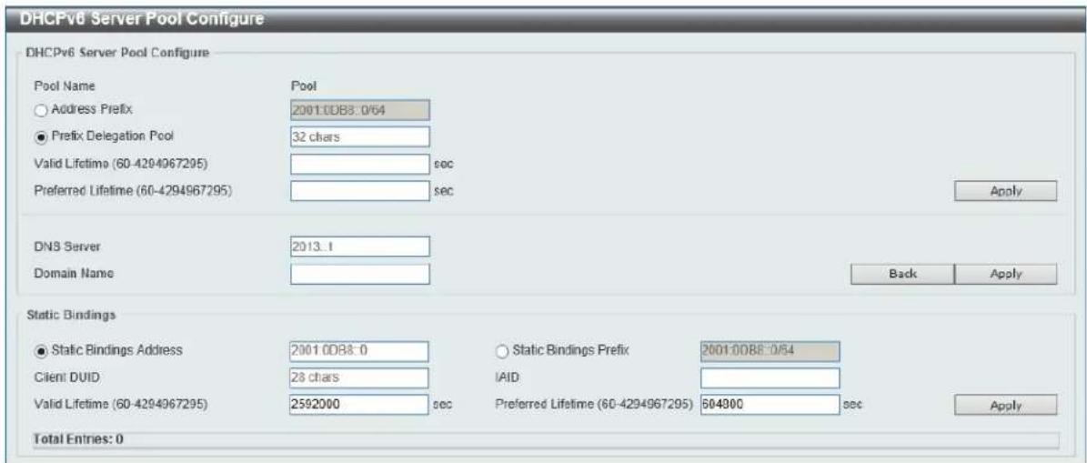
Figure 4-37 DHCPv6 Server Pool Settings (Configure) Window
The fields that can be configured in DHCPv6 Server Pool Configure are described below:
| Parameter Description | |
| Address Prefix | Select and enter the DHCPv6 server pool's IPv6 network address and prefix length here. For example, 2015::0/64. |
| Prefix Delegation Pool | Select and enter the DHCPv6 server pool's prefix delegation name here. This name can be up to 32 characters long. |
| Valid Lifetime | Enter the valid lifetime value here. The range is from 60 to 4294967295 seconds. The valid lifetime should be greater than preferred lifetime. If this value is not specified, then the default valid lifetime will be 2592000 seconds (30 days). |
| Preferred Lifetime | Enter the preferred lifetime value here. The range is from 60 to 4294967295 seconds. If this value is not specified, then the default preferred lifetime will be 604800 seconds (7 days). |
| DNS Server | Enter the DNS server's IPv6 address to be assigned to requesting DHCPv6 clients here. |
| Domain Name | Enter the domain name to be assigned to requesting DHCPv6 clients here. |
Click the Apply button to accept the changes made.
Click the Back button to return to the previous window.
The fields that can be configured in Static Bindings are described below:
| Parameter Description | |
| Static Bindings Address | Enter the static binding IPv6 address assign to the specific client here. |
| Static Bindings Prefix | Enter the static binding IPv6 network address and prefix length here. |
| Client DUID | Enter the client DHCP Unique Identifier (DUID) here. This string can be up to 28 characters long. |
| IAID | Enter the Identity Association Identifier (IAID) here. The IAID here uniquely identifies a collection of non-temporary addresses (IANA) assigned on the client. |
| Valid Lifetime | Enter the valid lifetime value here. The valid lifetime should be greaterthan the preferred lifetime. The range is from 60 to 4294967295 seconds. By default, this value is 2592000 seconds (30 days). |
| Preferred Lifetime | Enter the preferred lifetime value here. The range is from 60 to 4294967295 seconds. By default, this value is 604800 seconds (7 days). |
Click the Apply button to accept the changes made.
DHCPv6 Server Local Pool Settings
This window is used to view and configure the DHCPv6 server's local pool settings.
To view the following window, click Management > DHCP > DHCPv6 Server > DHCPv6 Server Local Pool Settings, as shown below:
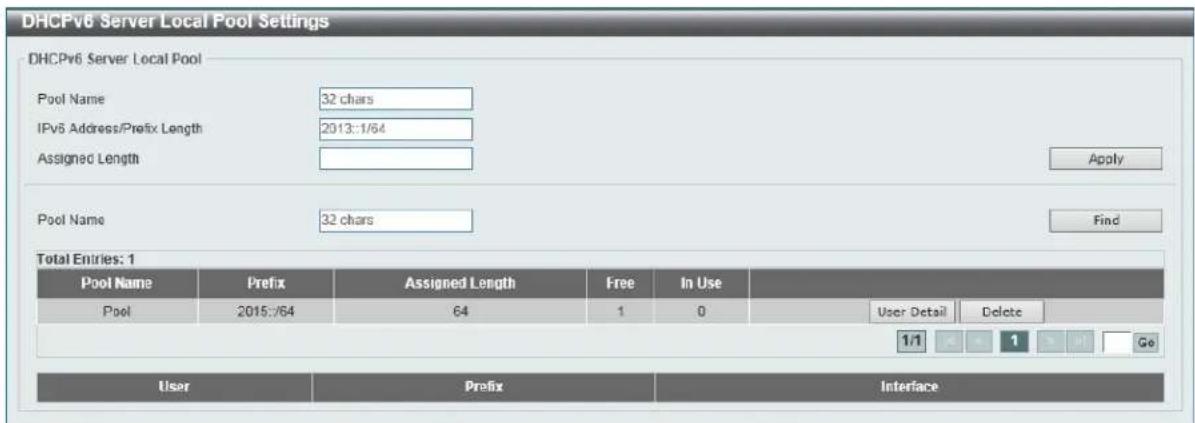
Figure 4-38 DHCPv6 Server Local Pool Settings Window
The fields that can be configured in DHCPv6 Server Local Pool are described below:
| Parameter Description | |
| Pool Name | Enter the DHCPv6 server's pool name here. This name can be up to 32 characters long. |
| IPv6 Address / Prefix Length | Enter the IPv6 prefix address and prefix length of the local pool here. |
| Assigned Length | Enter the prefix length to be delegated to the user from the pool here. The value of the assigned length cannot be less than the value of the prefix length. |
Click the Apply button to accept the changes made.
Click the Find button to locate a specific entry based on the information entered.
Click the User Detail button to view the user information displayed in the lower table.
Click the Delete button to remove the specified entry.
Enter a page number and click the Go button to navigate to a specific page when multiple pages exist.
DHCPv6 Server Exclude Address
This window is used to specify IPv6 addresses that a DHCPv6 server should not assign to DHCPv6 clients. The DHCPv6 server assumes that all addresses (excluding the switch's IPv6 address) can be
assigned to clients. Use this window to exclude a single IPv6 address or a range of IPv6 addresses. The excluded addresses are only applied to the pool(s) for address assignment.
To view the following window, click Management > DHCP > DHCPv6 Server > DHCPv6 Server Exclude Address, as shown below:
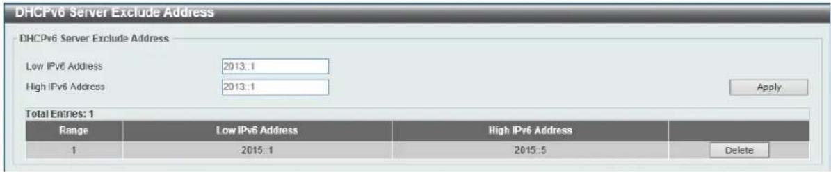
Figure 4-39 DHCPv6 Server Exclude Address Window
The fields that can be configured in DHCPv6 Server Exclude Address are described below:
| Parameter Description | |
| Low IPv6 Address | Enter the excluded IPv6 address or first IPv6 address in an excluded address range here. |
| High IPv6 Address | Optionally, enter the last IPv6 address in the excluded address range. |
Click the Apply button to accept the changes made.
Click the Delete button to remove the specified entry.
DHCPv6 Server Binding
This window is used to view and clear the DHCPv6 server's binding entries.
To view the following window, click Management > DHCP > DHCPv6 Server > DHCPv6 Server Binding, as shown below:

Figure 4-40 DHCPv6 Server Binding Window
The fields that can be configured in DHCPv6 Server Binding are described below:
| Parameter Description | |
| IPv6 Address | Enter the binding entry's IPv6 address to be displayed or cleared here. Select the All option to display or clear all DHCPv6 client prefix bindings in or from the binding table. |
Click the Find button to locate a specific entry based on the information entered.
Click the Clear button to clear the entries based on the information specified.
DHCPv6 Server Interface Settings
This window is used to view and configure the DHCPv6 server's interface settings.
To view the following window, click Management > DHCP > DHCPv6 Server > DHCPv6 Server Interface Settings, as shown below:
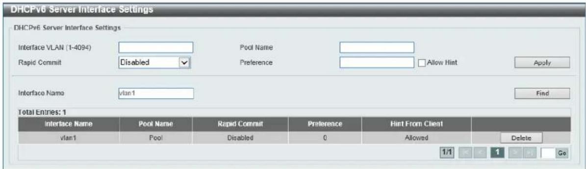
Figure 4-41 DHCPv6 Server Interface Settings Window
The fields that can be configured in DHCPv6 Server Interface Settings are described below:
| Parameter Description | |
| Interface VLAN | Enter the interface's VLAN ID here. The range is from 1 to 4094. |
| Pool Name | Enter the DHCPv6 server's pool name here. This name can be up to 32 characters long. |
| Rapid Commit | Select to allow the proceeding of two-message exchanges or not by enabling or disabling this option. By default, two-message exchange is not allowed. |
| Preference | Enter the preference value here. Select the Allow Hint option to allow hints. |
| Interface Name | Enter the interface's name here. |
Click the Apply button to accept the changes made.
Click the Find button to locate a specific entry based on the information entered.
Click the Delete button to remove the specified entry.
DHCPv6 Server Operational Information
This window is used to display the DHCPv6 server's operational information.
To view the following window, click Management > DHCP > DHCPv6 Server > DHCPv6 Server Operational Information, as shown below:

Figure 4-42 DHCPv6 Server Operational Information Window
DHCP Relay
DHCP Relay Pool Settings
This window is used to view and configure the DHCP relay pool on a DHCP relay agent.
To view the following window, click Management > DHCP > DHCP Relay > DHCP Relay Pool Settings, as shown below:
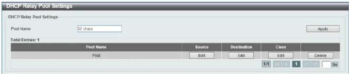
Figure 4-43 DHCP Relay Pool Settings Window
The fields that can be configured in DHCP Relay Pool Settings are described below:
| Parameter Description | |
| Pool Name | Enter the address pool name with a maximum of 32 characters. |
Click the Apply button to accept the changes made.
Click the Edit button to modify the corresponding information of the specific DHCP pool.
Click the Delete button to remove the specified entry.
Enter a page number and click the Go button to navigate to a specific page when multiple pages exist.
After clicking the Edit button under Source, the following window will appear.
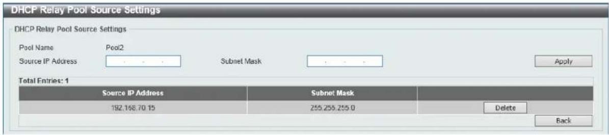
Figure 4-44 DHCP Relay Pool Settings (Source Edit) Window
The fields that can be configured in DHCP Relay Pool Source Settings are described below:
| Parameter Description | |
| Source IP Address | Enter the source subnet of client packets. |
| Subnet Mask | Enter the network mask of the source subnet. |
Click the Apply button to accept the changes made.
Click the Delete button to remove the specified entry.
Click the Back button to return to the previous window.
After clicking the Edit button under Destination, the following window will appear.
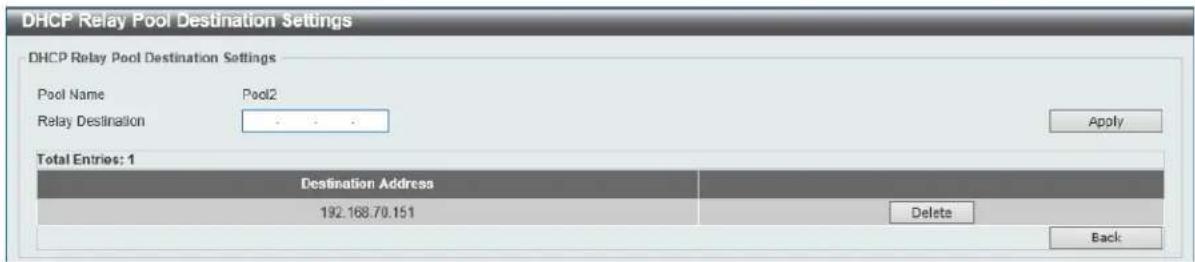
Figure 4-45 DHCP Relay Pool Settings (Destination Edit) Window
The fields that can be configured in DHCP Relay Pool Destination Settings are described below:
| Parameter Description | |
| Relay Destination | Enter the relay destination DHCP server IP address. |
Click the Apply button to accept the changes made.
Click the Delete button to remove the specified entry.
Click the Back button to return to the previous window.
After clicking the Edit button under Class, the following window will appear.
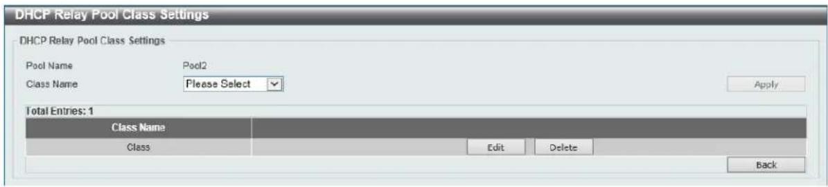
Figure 4-46 DHCP Relay Pool Settings (Class Edit) Window
The fields that can be configured in DHCP Relay Pool Class Settings are described below:
| Parameter Description | |
| Class Name | Select the DHCP class name. |
Click the Apply button to accept the changes made.
Click the Edit button to edit more information.
Click the Delete button to remove the specified entry.
Click the Back button to return to the previous window.
After clicking the Edit button, the following window will appear.
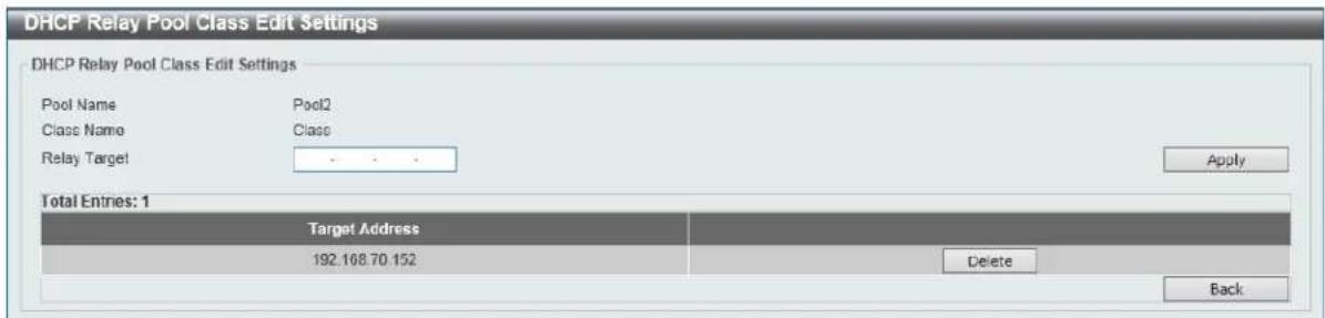
Figure 4-47 DHCP Relay Pool Settings (Class Edit, Edit) Window
The fields that can be configured in DHCP Relay Pool Class Edit Settings are described below:
| Parameter Description | |
| Relay Target | Enter the DHCP relay target for relaying packets that matches the value pattern of the option defined in the DHCP class. |
Click the Apply button to accept the changes made.
Click the Delete button to remove the specified entry.
Click the Back button to return to the previous window.
DHCP Relay Information Settings
This window is used to view and configure the DHCP relay information.
To view the following window, click Management > DHCP > DHCP Relay > DHCP Relay Information Settings, as shown below:
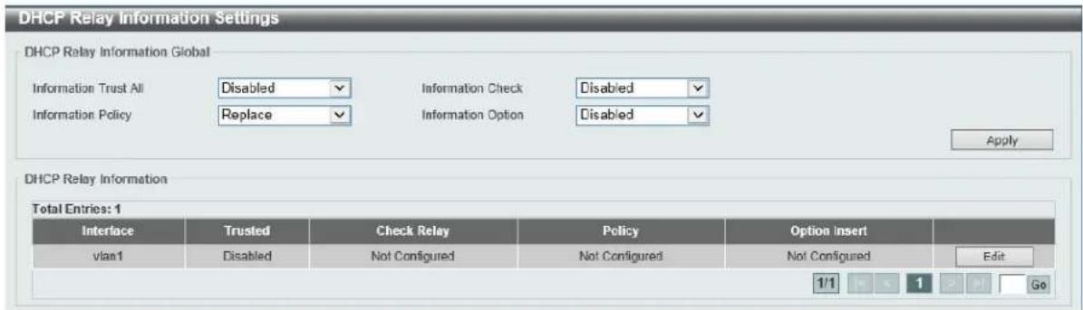
Figure 4-48 DHCP Relay Information Settings Window
The fields that can be configured in DHCP Relay Information Global are described below:
| Parameter Description | |
| Information Trust All | Select this option to enable or disable the DHCP relay agent to trust the IP DHCP relay information for all interfaces. |
| information Check | Select this option to enable or disable the DHCP relay agent to validate and remove the relay agent information option in the received DHCP reply packet. |
| Information Policy | Select the Option 82 re-forwarding policy for the DHCP relay agent. Options to choose from areKeep, Drop, andReplace.Keep- Select to discard the packet that already has the relay option.Drop- Select that the DHCP request packet that already has therelay option is left unchanged and directly relayed to the DHCP server.Replace - Select that the DHCP request packet that already has the relay option will be replaced by a new option. |
| Information Option | Select this option to enable or disable the insertion of relay agent information (Option 82) during the relay of DHCP request packets. |
Click the Apply button to accept the changes made.
Click the Edit button to modify the corresponding interface.
Enter a page number and click the Go button to navigate to a specific page when multiple pages exist.
DHCP Relay Information Option Format Settings
This window is used to view and configure the DHCP information format.
To view the following window, click Management > DHCP > DHCP Relay > DHCP Relay Information Option Format Settings, as shown below:

Figure 4-49 DHCP Relay Information Option Format Settings Window
The fields that can be configured in DHCP Relay Information Option Format Global are described below:
| Parameter Description | |
| Information Format Remote ID | Select the DHCP information remote ID sub-option. Options to choose from are Default, User Define, and Vendor2.Default - Select to use the Switch's system MAC address as the remote ID.User Define - Select to use a user-defined remote ID. Enter the user-defined string with the maximum of 32 characters in the text box.Vendor2 - Select to use vender 2 as the remote ID. |
| Information Format Circuit ID | Select the DHCP information circuit ID sub-option. Options to choose from are Default, User Define, and Vendor1.Default - Select to use the default circuit ID sub-option.User Define - Select to use a user-defined circuit ID. Enter the user-defined string with the maximum of 32 characters in the text box.Vendor1 - Select to use vender 1 as the circuit ID. |
Click the Apply button to accept the changes made.
DHCP Local Relay VLAN
This window is used to view and configure local relay on a VLAN or a group of VLANs.
To view the following window, click Management > DHCP > DHCP Relay > DHCP Local Relay VLAN, as shown below:

Figure 4-50 DHCP Local Relay VLAN Window
The fields that can be configured in DHCP Local Relay VLAN Settings are described below:
| Parameter Description | |
| DHCP Local Relay VID List | Enter the VLAN ID for DHCP local relay. Tick the All VLANs check box to select all VLANs. |
| State | Select this option to enable or disable the DHCP local relay on the specific VLAN(s). |
Click the Apply button to accept the changes made.
DHCPv6 Relay
DHCPv6 Relay Global Settings
This window is used to view and configure the DHCPv6 relay remote ID settings.
To view the following window, click Management > DHCP > DHCPv6 Relay > DHCPv6 Relay Global Settings, as shown below:

Figure 4-51 DHCPv6 Relay Global Settings Window
The fields that can be configured in DHCPv6 Relay Global Settings are described below:
| Parameter Description | |
| IPv6 DHCP Relay Remote ID Format | Select to choose the sub-type of the remote ID. Options to choose from are Default, CID with User Define, and User Define. |
| IPv6 DHCP Relay Remote ID UDF | Select to choose the User Define Field (UDF) for remote ID. Options to choose from are ASCII, and Hex.ASCI - Select to enter the ASCII string with a maximum of 128 characters in the text box.HEX - Select to enter the hexadecimal string with a maximum of 256 characters in the text box. |
| IPv6 DHCP Relay Remote ID Policy | Select to choose Option 37 forwarding policy for the DHCPv6 relay agent. Options to choose from are Keep, and Drop.Keep - Select to discard the packet that already has the relay agent Remote-ID Option 37.Drop - Select that the DHCPv6 request packet that already has the relay agent Remote-ID option is left unchanged and directly relayed to the DHCPv6 server. |
| IPv6 DHCP Relay Remote ID | Select this option to enable or disable the insertion of the relay agent |
| Option | remote ID Option 37 during the relay of DHCP for IPv6 request packets. |
Click the Apply button to accept the changes made.
DHCPv6 Relay Interface Settings
This window is used to view and configure the DHCPv6 relay interface settings.
To view the following window, click Management > DHCP > DHCPv6 Relay > DHCPv6 Relay Interface Settings, as shown below:
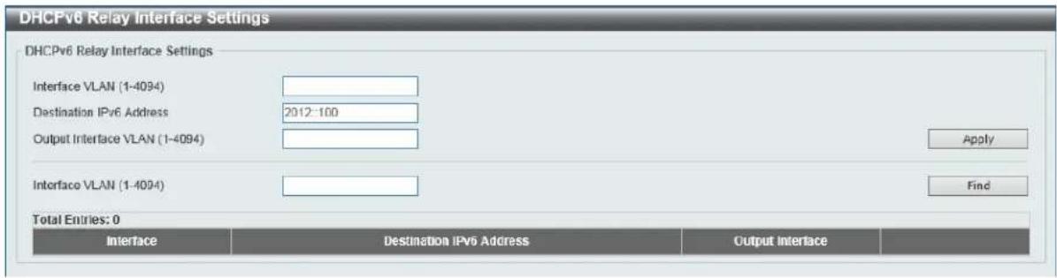
Figure 4-52 DHCPv6 Relay Interface Settings Window
The fields that can be configured in DHCPv6 Relay Interface Settings are described below:
| Parameter Description | |
| Interface VLAN | Enter the interface's VLAN ID used in the DHCPv6 relay here. The range is from 1 to 4094. |
| Destination IPv6 Address | Enter the DHCPv6 relay destination address. |
| Output Interface VLAN | Enter the output interface's VLAN ID for the relay destination here. The range is from 1 to 4094. |
Click the Apply button to accept the changes made.
Click the Find button to locate a specific entry based on the information entered.
Click the Delete button to remove the specified entry.
Enter a page number and click the Go button to navigate to a specific page when multiple pages exist.
DHCP Auto Configuration
This window is used to view and configure the DHCP auto-configuration function.
To view the following window, click Management > DHCP Auto Configuration, as shown below:

Figure 4-53 DHCP Auto Configuration Window
The fields that can be configured in DHCP Auto Configuration are described below:
| Parameter Description | |
| Auto Configuration State | Select this option to enable or disable the auto-configuration function. |
Click the Apply button to accept the changes made.
DNS
Computer users usually prefer to use text names for computers for which they may want to open a connection. Computers themselves, require 32 bit IP addresses. Somewhere, a database of network devices' text names and their corresponding IP addresses must be maintained.
The Domain Name System (DNS) is used to map names to IP addresses throughout the Internet and has been adapted for use within intranets. For two DNS servers to communicate across different subnets, the DNS Relay of the Switch must be used. The DNS servers are identified by IP addresses.
Mapping Domain Names to Addresses
Name-to-address translation is performed by a program called a Name server. The client program is called a Name resolver. A Name resolver may need to contact several Name servers to translate a name to an address.
The Domain Name System (DNS) servers are organized in a somewhat hierarchical fashion. A single server often holds names for a single network, which is connected to a root DNS server - usually maintained by an ISP.
Domain Name Resolution
The domain name system can be used by contacting the name servers one at a time, or by asking the domain name system to do the complete name translation. The client makes a query containing the name, the type of answer required, and a code specifying whether the domain name system should do the entire name translation, or simply return the address of the next DNS server if the server receiving the query cannot resolve the name.
When a DNS server receives a query, it checks to see if the name is in its sub domain. If it is, the server translates the name and appends the answer to the query, and sends it back to the client. If the DNS server cannot translate the name, it determines what type of name resolution the client requested. A complete translation is called recursive resolution and requires the server to contact other DNS servers until the name is resolved. Iterative resolution specifies that if the DNS server cannot supply an answer, it returns the address of the next DNS server the client should contact.
Each client must be able to contact at least one DNS server, and each DNS server must be able to contact at least one root server.
The address of the machine that supplies domain name service is often supplied by a DHCP or BOOTP server, or can be entered manually and configured into the operating system at startup.
DNS Global Settings
This window is used to view and configure the DNS global settings.
To view the following window, click Management > DNS > DNS Global Settings, as shown below:
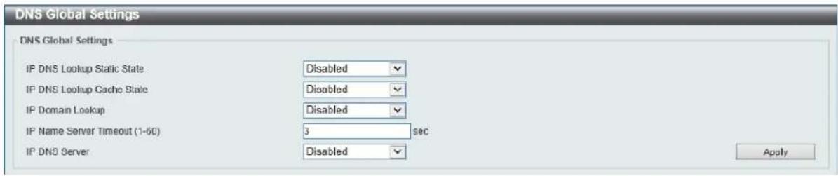
Figure 4-54 DNS Global Settings Window
The fields that can be configured in DNS Global Settings are described below:
| Parameter Description | |
| IP DNS Lookup Static State | Select to enable or disable the IP DNS lookup static state here. |
| IP DNS Lookup Cache State | Select to enable or disable the IP DNS lookup cache state here. |
| IP Domain Lookup | Select to enable or disable the IP domain lookup state here. |
| IP Name Server Timeout | Enter the maximum time to wait for a response from a specified name server. This value is between 1 and 60 seconds. |
| IP DNS Server | Select the globally enable or disable the DNS server feature here. |
Click the Apply button to accept the changes made.
DNS Name Server Settings
This window is used to view and configure the IP address of a domain name server.
To view the following window, click Management > DNS > DNS Name Server Settings, as shown below:
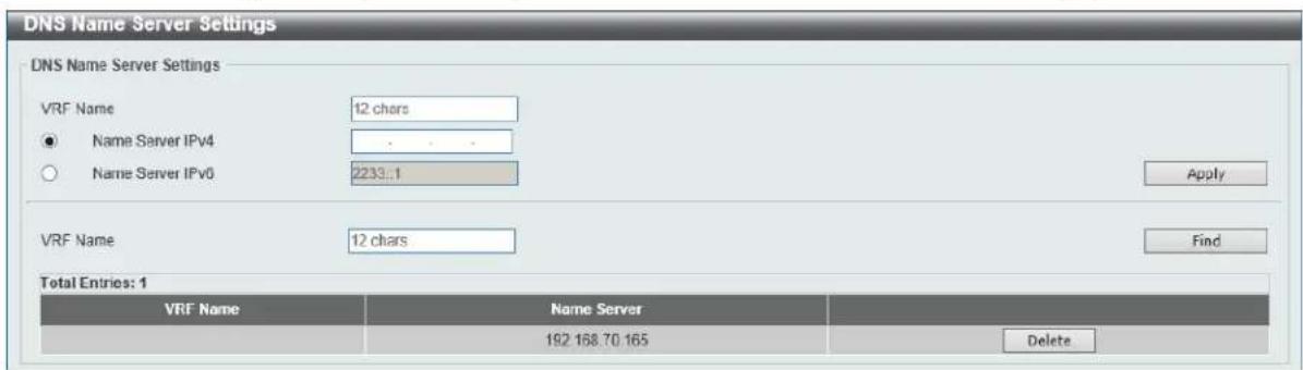
Figure 4-55 DNS Name Server Settings Window
The fields that can be configured in DNS Name Server Settings are described below:
| Parameter Description | |
| VRF Name | Enter the VRF instance's name that will be used in this configuration or search here. This name can be up to 12 characters long. |
| Name Server IPv4 | Select and enter the IPv4 address of the DNS server. |
| Name Server IPv6 | Select and enter the IPv6 address of the DNS server. |
Click the Apply button to accept the changes made.
Click the Find button to locate a specific entry based on the information entered.
Click the Delete button to remove the specified entry.
DNS Host Settings
This window is used to view and configure the static mapping entry for the host name and the IP address in the host table.
To view the following window, click Management > DNS > DNS Host Settings, as shown below:
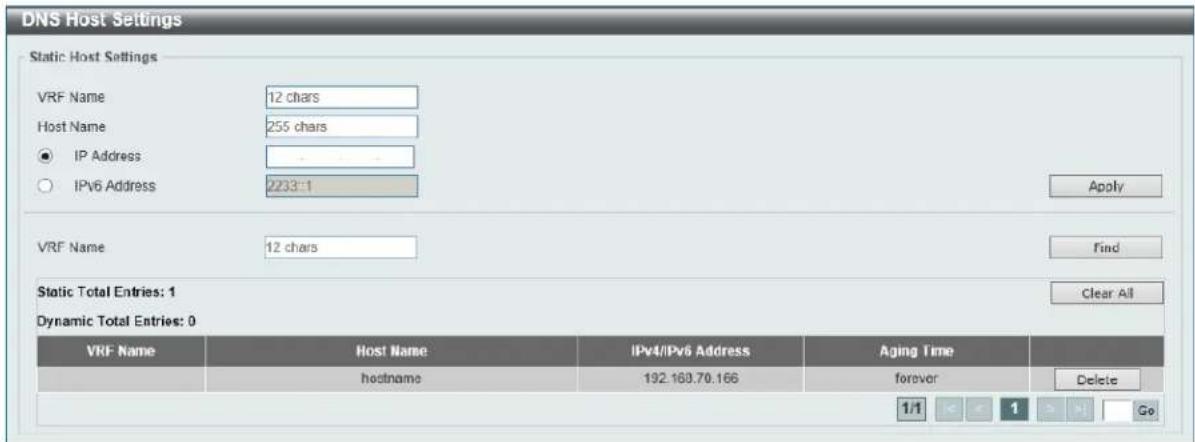
Figure 4-56 DNS Host Settings Window
The fields that can be configured in Static Host Settings are described below:
| Parameter Description | |
| VRF Name | Enter the VRF instance's name that will be used in this configuration or search here. This name can be up to 12 characters long. |
| Host Name | Enter the host name of the equipment. |
| IP Address | Select and enter the IPv4 address of the equipment. |
| IPv6 Address | Select and enter the IPv6 address of the equipment. |
Click the Apply button to accept the changes made.
Click the Find button to locate a specific entry based on the information entered.
Click the Clear All button to clear the information entered in all the fields on this page.
Click the Delete button to remove the specified entry.
IP Source Interface
This window is used to view and configure the IP source interface settings.
To view the following window, click Management > IP Source Interface, as shown below:
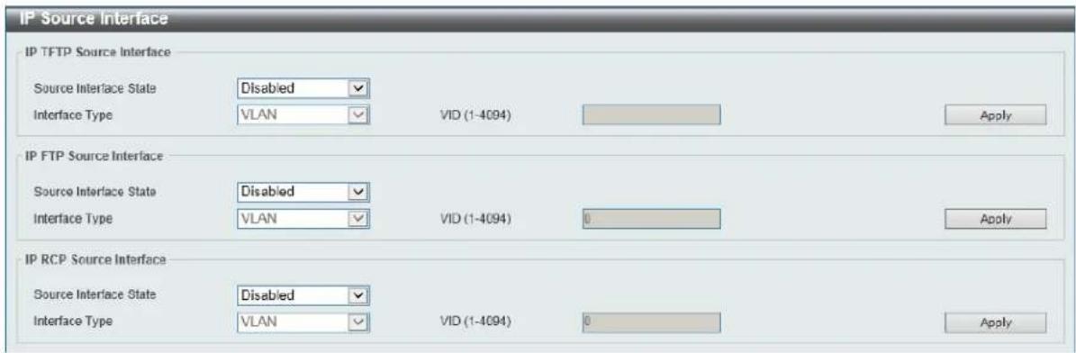
Figure 4-57 IP Source Interface Window
The fields that can be configured in IP TFTP Source Interface are described below:
| Parameter Description | |
| Source Interface State | Select to enable or disable the IP TFTP source interface's state here. |
| Interface Type | After enabling the Source Interface State option, select the interface type here. Options to choose from are Loopback, Mgmt, and VLAN. |
| VID | Enter the interface's ID here. For loopback interfaces this value is from 1 to 8. For the management interface (Mgmt) this value can only be 0. For VLAN interfaces this value is from 1 to 4094. |
Click the Apply button to accept the changes made.
The fields that can be configured in IP FTP Source Interface are described below:
| Parameter Description | |
| Source Interface State | Select to enable or disable the IP FTP source interface's state here. |
| Interface Type | After enabling the Source Interface State option, select the interface type here. Options to choose from are Loopback, Mgmt, and VLAN. |
| VID | Enter the interface's ID here. For loopback interfaces this value is from 1 to 8. For the management interface (Mgmt) this value can only be 0. For VLAN interfaces this value is from 1 to 4094. |
Click the Apply button to accept the changes made.
The fields that can be configured in IP RCP Source Interface are described below:
| Parameter Description | |
| Source Interface State | Select to enable or disable the IP RCP source interface's state here. |
| Interface Type | After enabling the Source Interface State option, select the interface type here. Options to choose from are Loopback, Mgmt, and VLAN. |
| VID | Enter the interface's ID here. For loopback interfaces this value is from 1 to 8. For the management interface (Mgmt) this value can only be 0. For VLAN interfaces this value is from 1 to 4094. |
Click the Apply button to accept the changes made.
File System
This window is used to view, manage and configure the switch's file system.
To view the following window, click Management > File System, as shown below:
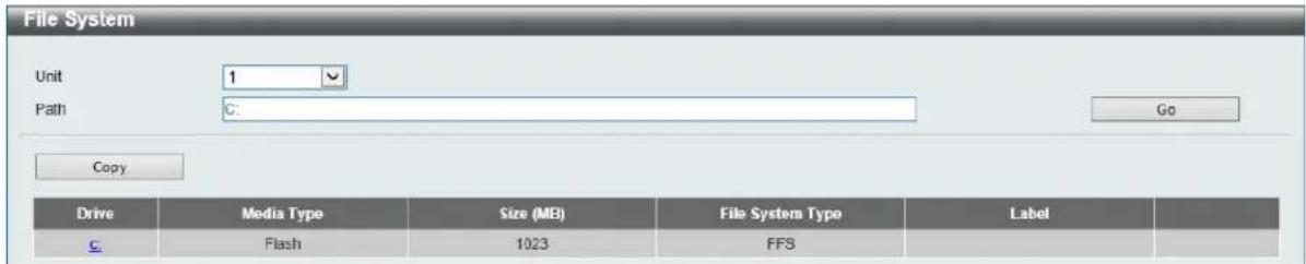
Figure 4-58 File System Window
The fields that can be configured are described below:
| Parameter Description | |
| Unit | Select the switch unit that will be used for this configuration here. |
| Path | Enter the path string |
Click the Go button to navigate to the path entered.
Click the c: hyperlink to navigate the C: drive
After clicking the c: hyperlink, the following window will appear:
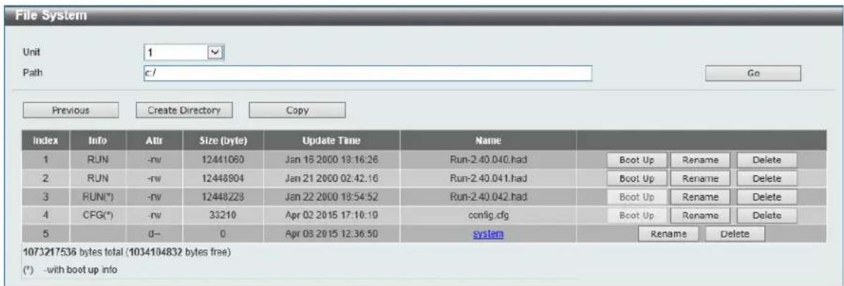
Figure 4-59 File System (Drive) Window
Click the Previous button to return to the previous window.
Click the Create Directory to create a new directory within the file system of the Switch.
Click the Copy button to copy a specific file to the Switch.
Click the Boot Up button to set a specific runtime image as the boot up image.
Click the Rename button to rename a specific file's name.
Click the Delete button to remove a specific file from the file system.

NOTE: If the boot configuration file is damaged, the Switch will automatically revert back to the default configuration.

NOTE: If the boot image file is damaged, the Switch will automatically use the backup image file in the next boot up.
Click the Copy button to see the following window.
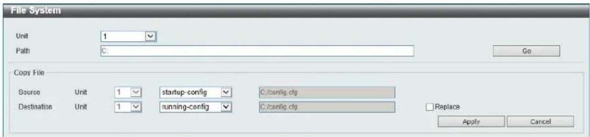
Figure 4-60 File System (Copy) Window
The fields that can be configured in Copy File are described below:
| Parameter Description | |
| Source | Select the source file's switch Unit ID. Select the type of source file that will be copied next. Options to choose from are startup-config and Source File. Only after selecting the Source File option can the source file's path and filename be entered in the space provided. |
| Destination | Select the destination file's switch Unit ID. Select the type of destination file that will be copied next. Options to choose from are startup-config, running-config, and Destination File. Only after selecting the Destination File option can the destination file's path and filename be entered in the space provided. Tick the Replace check box to replace the current running configuration with the indicated configuration file. |
Click the Apply button to initiate the copy.
Click the Cancel button the discard the process.
Physical Stacking
The switch supports stacking 4 switches together while being managed by one IP address through Telnet, the Web User Interface, the RJ45 console port or through SNMP. This cost effective switch provides an affordable solution for administrators to upgrade their networks using either the DXS-3600-EM-Stack or the DXS-3600-EM-4QXS modules to scale and stack the switches. This increases overall reliability, serviceability, and availability.
- Duplex Chain - The duplex chain topology stacks switches together in a chain-link format. Using this method, data transfer is only possible in one direction and if there is a break in the chain, then data transfer will obviously be affected.
- Duplex Ring - The duplex ring stacks switches in a ring or circle format where data can be transferred in two directions. This topology is very resilient due to the fact that if there is a break in the ring, data can still be transferred through the stacking cables between switches in the stack.
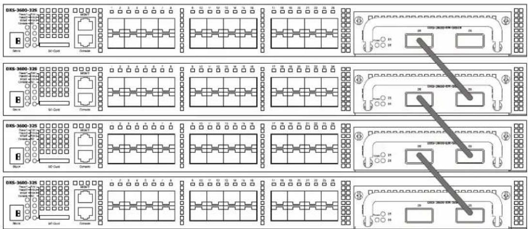
Figure 4-61 Switches stacked in a Duplex Chain
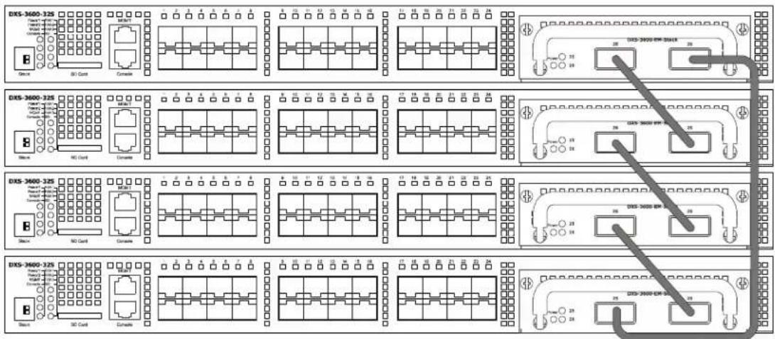
Figure 4-62 Switches stacked in a Duplex Ring
Within each of these topologies, each switch plays a role in the Switch stack. These roles can be set by the user per individual Switch, or if desired, can be automatically determined by the Switch stack. Three possible roles exist when stacking with the Switch.
Primary Master - The Primary Master is the leader of the stack. It will maintain normal operations, monitor operations and the running topology of the Stack. This switch will also assign Stack Unit IDs, synchronize configurations and transmit commands to remaining switches in the switch stack. The Primary Master can be manually set by assigning this Switch the highest priority (a lower number denotes a higher priority) before physically assembling the stack, or it can be determined automatically by the stack through an election process which determines the lowest MAC address and then will assign that switch as the Primary Master, if all priorities are the same. The Primary master are physically displayed by the seven segment LED to the far right on the front panel of the switch where this LED will flash between its given Box ID and 'H'.
Backup Master - The Backup Master is the backup to the Primary Master, and will take over the functions of the Primary Master if the Primary Master fails or is removed from the Stack. It also monitors the status of neighboring switches in the stack, will perform commands assigned to it by the Primary Master and will monitor the running status of the Primary Master. The Backup Master can be set by the user by assigning this Switch the second highest priority before physically assembling the stack, or it can be determined automatically by the stack through an election process which determines the second lowest MAC address and then will assign that switch as the Backup Master, if all priorities are the same. The Backup master are physically displayed by the seven segment LED to the far right on the front panel of the switch where this LED will flash between its given Box ID and 'h'.
Slave - Slave switches constitute the rest of the switch stack and although not Primary or Backup Masters, they can be placed into these roles when these other two roles fail or are removed from the stack. Slave switches perform operations requested by the master, monitor the status of neighbor switches in the stack and the stack topology and adhere to the Backup Master's commands once it becomes a Primary Master. Slave switches will do a self-check to determine if it is to become the Backup Master if the Backup Master is promoted to the Primary Master, or if the Backup Master fails or is removed from the switch stack. If both Primary and Backup masters fail, or are removed from the Switch stack, it will determine if it is to become the Primary Master. These roles will be determined, first by priority and if the priority is the same, the lowest MAC address.
Once switches have been assembled in the topology desired by the user and powered on, the stack will undergo three processes until it reaches a functioning state.
- Initialization State - This is the first state of the stack, where the runtime codes are set and initialized and the system conducts a peripheral diagnosis to determine each individual switch is functioning properly.
- Master Election State - Once the codes are loaded and initialized, the stack will undergo the Master Election State where it will discover the type of topology used, elect a Primary Master and then a Backup Master.
- Synchronization State - Once the Primary Master and the Backup Master have been established, the Primary Master will assign Stacking Unit IDs to switches in the stack, synchronize configurations for all switches and then transmit commands to the rest of the switches based on the users configurations of the Primary Master.
Once these steps have been completed, the switch stack will enter a normal operating mode.
Stack Switch Swapping
The stacking feature of the Switch supports “hot swapping” of switches in and out of the running stack. Users may remove or add switches to the stack without powering down or largely affecting the transfer of data between switches in the stack, with a few minor provisions.
When switches are “hot inserted” into the running stack, the new switch may take on the Primary Master, Backup Master or Slave role, depending on configurations set on the newly added switch, such as configured priority or MAC address. Yet, if adding two stacks together that have both previously undergone the election process, and therefore both have a Primary Master and a Backup master, a new Primary Master will be elected from one of the already existing Primary Masters, based on priority or MAC address. This Primary Master will take over all of the Primary Master’s roles for all new switches that were hot inserted. This process is done using discovery packets that circulate through the switch stack every 1.5 seconds until the discovery process has been completed.
The “hot remove” action means removing a device from the stack while the stack is still running. The hot removal is detected by the stack when it fails to receive heartbeat packets during its specified interval from a device, or when one of the stacking ports links is down. Once the device has been removed, the remaining switches will update their stacking topology database to reflect the change. Any one of the three roles, Primary Master, Backup Master or Slave, may be removed from the stack, yet different processes occur for each specific device removal.
If a Slave device has been removed, the Primary Master will inform other switches of the hot remove of this device through the use of unit leave messages. Switches in the stack will clear the configurations of the unit removed, and dynamically learned databases, such as ARP, will be cleared as well.
If the Backup Master has been hot removed, a new Backup Master will be chosen through the election process previously described. Switches in the stack will clear the configurations of the unit removed, and dynamically learned databases, such as ARP, will be cleared as well. Then the Backup Master will begin backing up the Primary Master when the database synchronization has been completed by the stack.
If the Primary Master is removed, the Backup Master will assume the Primary Master's role and a new Backup Master will be chosen using the election process. Switches in the stack will clear the configurations of the unit removed, and dynamically learned databases, such as ARP, will be cleared as well. The new Primary Master will inherit the MAC and IP address of the previous Primary Master to avoid conflict within the stack and the network itself.
If both the Primary Master and the Backup Master are removed, the election process is immediately processed, and a new Primary Master and Backup Master are determined. Switches in the stack will clear the configurations of the units removed, and dynamically learned databases, such as ARP, will be cleared as well. Static switch configurations still remain in the database of the remaining switches in the stack and those functions will not be affected.

NOTE: If there is a Box ID conflict when the stack is in the discovery phase, the device will enter a special standalone topology mode. Users can only get device information, configure Box IDs, save and reboot. All stacking ports will be disabled and an error message will be produced on the local console port of each device in the stack. Users must reconfigure Box IDs and reboot the stack.
To view the following window, click Management > Physical Stacking, as shown below:
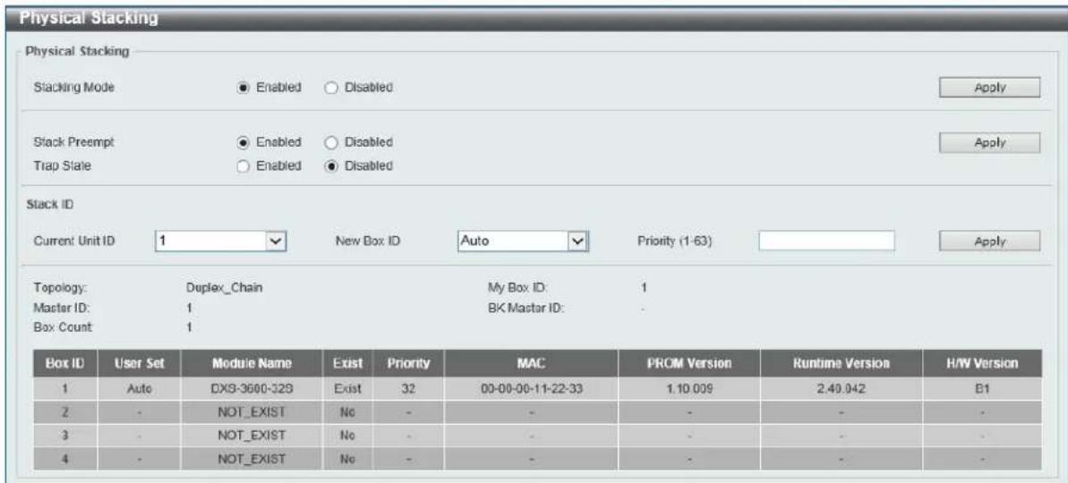
Figure 4-63 Physical Stacking Window
The fields that can be configured in Physical Stacking are described below:
| Parameter Description | |
| Stacking Mode | Select this option to enable or disable the stacking mode. |
| Stack Preempt | Select this option to enable or disable preemption of the master role to come into play when a unit with a better priority is added to the Switch later. |
| Trap State | Select this option to enable or disable sending of stacking related traps. |
Click the Apply button to accept the changes made.
The fields that can be configured in Stack ID are described below:
| Parameter Description | |
| Current Unit ID | Select the unit ID of the switch in the stack. |
| New Box ID | Select the new box ID for the switch that is selected in the Current Unit ID. The user may choose any number between 1 and 4 to identify the switch in the switch stack. Auto will automatically assign a box number to the switch in the switch stack. |
| Priority | Enter the priority of the switch stacking unit. The range is from 1 to 63. |
Click the Apply button to accept the changes made.
Virtual Stacking (SIM)
D-Link Single IP Management (SIM) is a concept that will stack switches together over Ethernet instead of using stacking ports or modules. There are some advantages in implementing the Single IP Management feature:
- SIM can simplify management of small workgroups or wiring closets while scaling the network to handle increased bandwidth demand.
• SIM can reduce the number of IP address needed in your network. - SIM can eliminate any specialized cables for stacking connectivity and remove the distance barriers that typically limit your topology options when using other stacking technology.
Switches using D-Link Single IP Management (labeled here as SIM) must conform to the following rules:
- SIM is an optional feature on the Switch and can easily be enabled or disabled through the Command Line Interface or Web Interface. SIM grouping has no effect on the normal operation of the Switch in the user's network.
- There are three classifications for switches using SIM. The Commander Switch (CS), which is the master switch of the group, Member Switch (MS), which is a switch that is recognized by the CS a member of a SIM group, and a Candidate Switch (CaS), which is a Switch that has a physical link to the SIM group but has not been recognized by the CS as a member of the SIM group.
- A SIM group can only have one Commander Switch (CS).
- A SIM group accepts up to 32 switches (numbered 1-32), not including the Commander Switch (numbered 0).
- Members of a SIM group cannot cross a router.
- There is no limit to the number of SIM groups in the same IP subnet (broadcast domain); however a single switch can only belong to one group.
- If multiple VLANs are configured, the SIM group will only utilize the management VLAN on any switch.
- SIM allows intermediate devices that do not support SIM. This enables the user to manage switches that are more than one hop away from the CS.
The SIM group is a group of switches that are managed as a single entity. The Switch may take on three different roles:
- Commander Switch (CS) - This is a switch that has been manually configured as the controlling device for a group, and takes on the following characteristics:
■ It has an IP Address.
It is not a command switch or member switch of another Single IP group.
It is connected to the member switches through its management VLAN.
- Member Switch (MS) - This is a switch that has joined a single IP group and is accessible from the CS, and it takes on the following characteristics:
- It is not a CS or MS of another IP group.
- It is connected to the CS through the CS management VLAN.
- Candidate Switch (CaS) - This is a switch that is ready to join a SIM group but is not yet a member of the SIM group. The Candidate Switch may join the SIM group of the Switch by manually configuring it to be a MS of a SIM group. A switch configured as a CaS is not a member of a SIM group and will take on the following characteristics:
It is not a CS or MS of another Single IP group.
- It is connected to the CS through the CS management VLAN
The following rules also apply to the above roles:
• Each device begins in a Candidate state.
- The user can manually configure a CS to become a CaS.
- A CS must change its role to CaS and then to MS, to become a MS of a SIM group. Thus, the CS cannot directly be converted to a MS.
• A MS can become a CaS by:
- Being configured as a CaS through the CS.
- If report packets from the CS to the MS time out.
- The user can manually configure a CaS to become a CS
- The CaS can be configured through the CS to become a MS.
After configuring one switch to operate as the CS of a SIM group, additional DXS-3600 Series switches may join the group by manually configuring the Switch to be a MS. The CS will then serve as the in band entry point for access to the MS. The CS's IP address will become the path to all MS's of the group and the CS's Administrator's password, and/or authentication will control access to all MS's of the SIM group.
With SIM enabled, the applications in the CS will redirect the packet instead of executing the packets. The applications will decode the packet from the administrator, modify some data, and then send it to the MS. After execution, the CS may receive a response packet from the MS, which it will encode and send it back to the administrator.
When a CaS becomes a MS, it automatically becomes a member of the first SNMP community (includes read/write and read only) to which the CS belongs. However, if a MS has its own IP address, it can belong to SNMP communities to which other switches in the group, including the CS, do not belong.
Upgrade to v1.61
To better improve SIM management, the DXS-3600 Series switches have been upgraded to version 1.61 in this release. Many improvements have been made, including the Commander Switch (CS) now has the capability to automatically rediscover member switches that have left the SIM group, either through a reboot or web malfunction. This feature is accomplished through the use of Discover packets and Maintenance packets that previously set SIM members will emit after a reboot. Once a MS has had its MAC address and password saved to the CS's database, if a reboot occurs in the MS, the CS will keep this MS information in its database and when a MS has been rediscovered, it will add the MS back into the SIM tree automatically. No configuration will be necessary to rediscover these switches.
There are some instances where pre-saved MS switches cannot be rediscovered. For example, if the Switch is still powered down, if it has become the member of another group, or if it has been configured to be a Commander Switch, the rediscovery process cannot occur.
The topology map now includes new features for connections that are a member of a port trunking group. It will display the speed and number of Ethernet connections creating this port trunk group, as shown in the adjacent picture.
This version will support switch upload and downloads for firmware, configuration files and log files, as follows:
- Firmware - The switch now supports MS firmware downloads from a TFTP server.
- Configuration Files - This switch now supports downloading and uploading of configuration files both to (for configuration restoration) and from (for configuration backup) MS's, using a TFTP server.
- Log - The Switch now supports uploading MS log files to a TFTP server.
The user may zoom in and zoom out when utilizing the topology window to get a better, more defined view of the configurations.
Single IP Settings
This window is used to view and configure the SIM settings. The switch is set as a Candidate (CaS) as the factory default configuration and Single IP Management is disabled.
To view the following window, click Management > Virtual Stacking (SIM) > Single IP Settings, as shown below:
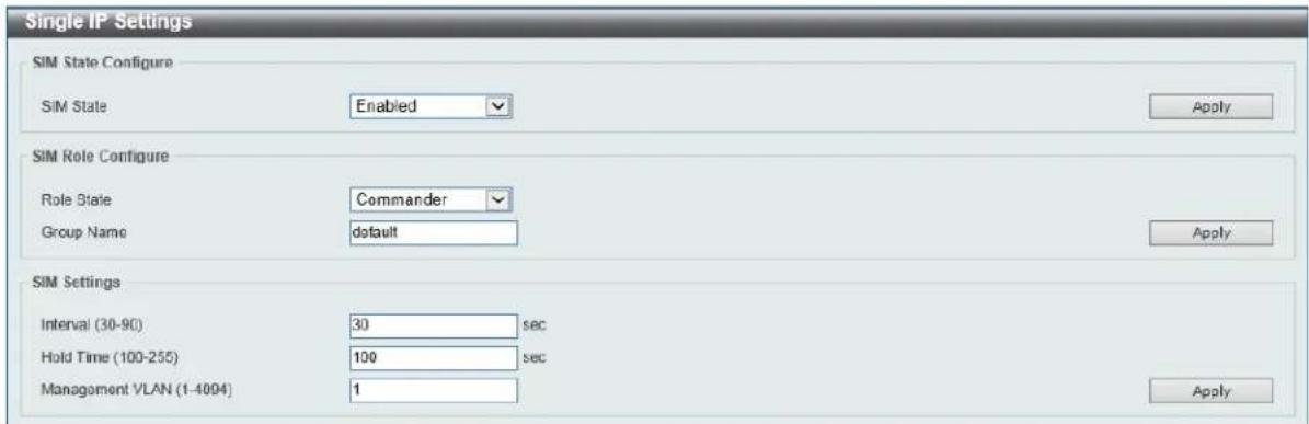
Figure 4-64 Single IP Settings Window
The fields that can be configured in SIM State Configure are described below:
| Parameter Description | |
| SIM State | Select this option to enable or disable the SIM state on the Switch.SelectDisabledto render all SIM functions on the Switch inoperable. |
Click the Apply button to accept the changes made.
The fields that can be configured in SIM Role Configure are described below:
| Parameter Description | |
| Role State | Select to change the SIM role of the Switch. Options to choose from are Candidate, and Commander.Candidate- A Candidate Switch (CaS) is not the member of a SIM group but is connected to a Commander Switch. This is the default setting for the SIM role of the Switch.Commander- Select to make the Switch a Commander Switch (CS). The user may join other switches to this Switch, over Ethernet, to be part of its SIM group. Choosing this option will also enable the Switch to be configured for SIM. |
| Group Name | Enter a group name. This is optional. This name is used to segment switches into different SIM groups. |
Click the Apply button to accept the changes made.
The fields that can be configured in SIM Settings are described below:
| Parameter Description | |
| Interval | Enter the interval in seconds. The range is from 30 to 90. |
| Hold Time | Enter the hold-time in seconds. The range is from 100 to255. |
| Management VLAN | Enter the single IP management message VLAN ID. |
Click the Apply button to accept the changes made.
After enabling the Switch to be a Commander Switch (CS), the Single IP Management folder will then contain four added links to aid the user in configuring SIM through the web, including Topology, Firmware Upgrade, Configuration Backup/Restore and Upload Log File.
Topology
This window is used to view, manage and configure the switch within the SIM group and requires Java script to function properly on your computer.
To view the following window, click Management > Virtual Stacking (SIM) > Topology, as shown below:
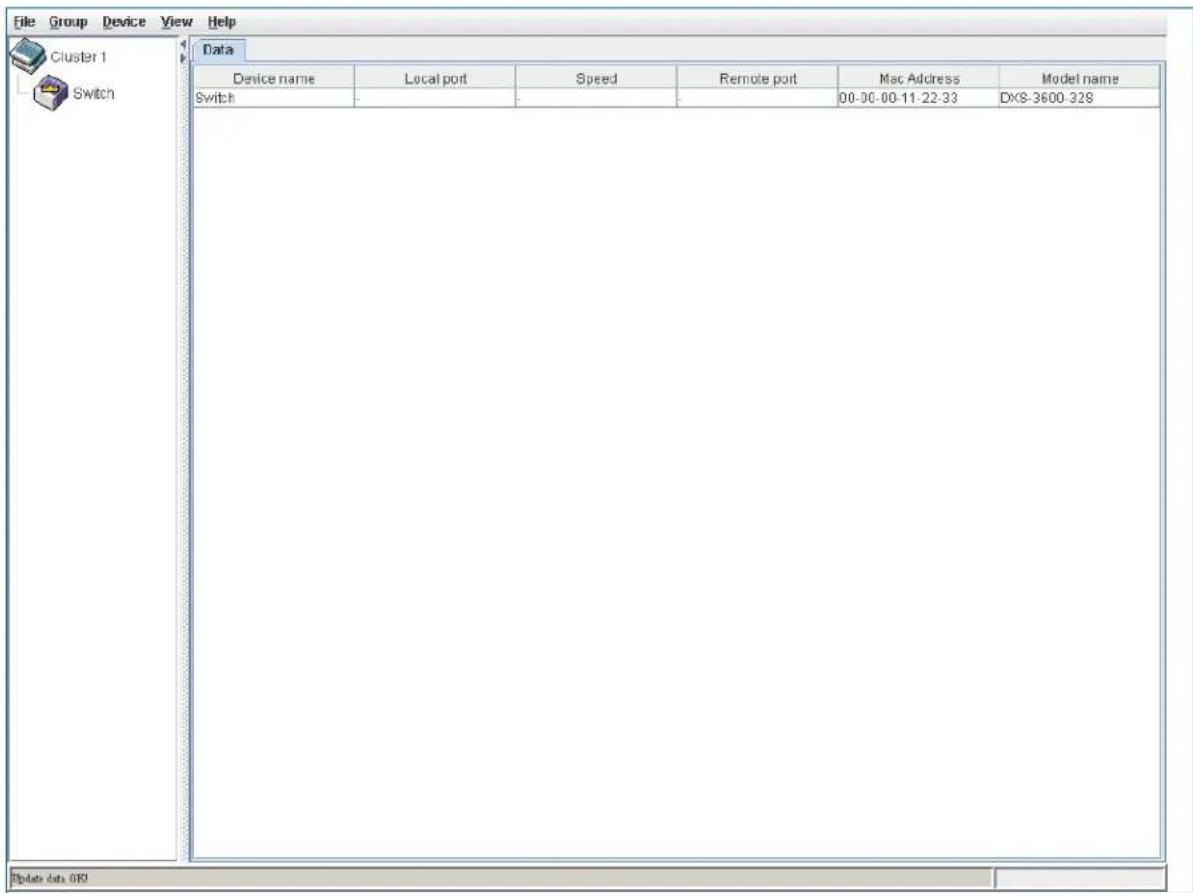
Figure 4-65 Topology Window
The fields that can be configured are described below:
| Parameter Description | |
| Device Name | Display the Device Name of the switches in the SIM group configured by the user. If no device is configured by the name, it will be given the name default and tagged with the last six digits of the MAC Address to identify it. |
| Local Port | Display the number of the physical port on the CS that the MS or CaS is connected to. The CS will have no entry in this field. |
| Speed | Display the connection speed between the CS and the MS or CaS. |
| Remote Port | Display the number of the physical port on the MS or CaS to which the CS is connected. The CS will have no entry in this field. |
| MAC Address | Display the MAC Address of the corresponding Switch. |
| Model Name | Display the full Model Name of the corresponding Switch. |
To view the Topology View window, open the View drop-down menu in the toolbar and then click Topology, which will open the following Topology Map. This window will refresh itself periodically (20 seconds by default).
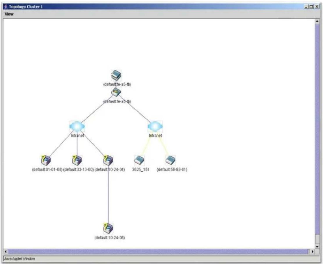
flowchart
graph TD
    A["(default fe-a5-fb)"] --> B["Intranet"]
    C["(default fe-a5-fb)"] --> B
    B --> D["(default 01-01-00)"]
    B --> E["(default 33-13-00)"]
    B --> F["(default 10-24-04)"]
    B --> G["(default 10-24-05)"]
    H["(default 58-83-01)"] --> I["3625_151"]
Figure 4-66 Topology View
This window will display how the devices within the Single IP Management Group connect to other groups and devices. Possible icons on this window are as follows:
| Icon | Description | Icon | Description |
 | Group |  | Layer 3 member switch |
 | Layer 2 commander switch |  | Member switch of other group |
 | Layer 3 commander switch |  | Layer 2 candidate switch |
 | Commander switch of other group |  | Layer 3 candidate switch |
 | Layer 2 member switch |  | Unknown device |
 | Non-SIM devices | ||
Tool Tips
In the Topology view window, the mouse plays an important role in configuration and in viewing device information. Setting the mouse cursor over a specific device in the topology window (tool tip) will display the same information about a specific device as the Tree view does. See the window below for an example.



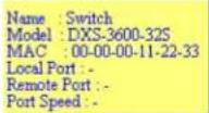

Figure 4-67 Device Information Utilizing the Tool Tip
Setting the mouse cursor over a line between two devices will display the connection speed between the two devices, as shown below.
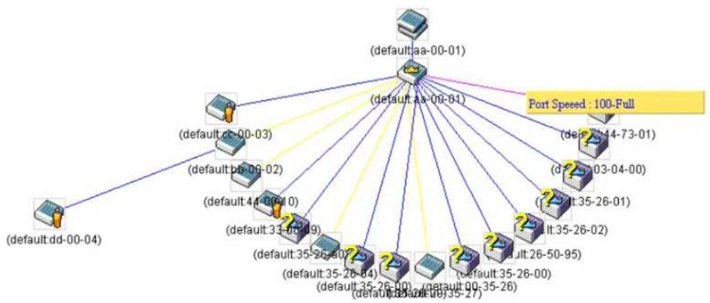
flowchart
graph TD
    A["(default:aa-00-01)"] --> B["(default:aa-00-01)"]
    A --> C["(default:aa-00-04)"]
    A --> D["(default:aa-00-03)"]
    A --> E["(default:aa-00-02)"]
    A --> F["(default:aa-00-01)"]
    A --> G["(default:aa-00-01)"]
    A --> H["(default:aa-00-01)"]
    A --> I["(default:aa-00-01)"]
    A --> J["(default:aa-00-01)"]
    A --> K["(default:aa-00-01)"]
    A --> L["(default:aa-00-01)"]
    A --> M["(default:aa-00-01)"]
    A --> N["(default:aa-00-01)"]
    A --> O["(default:aa-00-01)"]
    A --> P["(default:aa-00-01)"]
    A --> Q["(default:aa-00-01)"]
    A --> R["(default:aa-00-01)"]
    A --> S["(default:aa-00-01)"]
    A --> T["(default:aa-00-01)"]
    A --> U["(default:aa-00-01)"]
    A --> V["(default:aa-00-01)"]
    A --> W["(default:aa-00-01)"]
    A --> X["(default:aa-00-01)"]
    A --> Y["(default:aa-00-01)"]
    A --> Z["(default:aa-00-01)"]
    A --> AA["(default:aa-00-01)"]
    A --> AB["(default:aa-00-01)"]
    A --> AC["(default:aa-00-01)"]
    A --> AD["(default:aa-00-01)"]
    A --> AE["(default:aa-00-01)"]
    A --> AF["(default:aa-00-01)"]
    A --> AG["(default:aa-00-01)"]
    A --> AH["(default:aa-00-01)"]
    A --> AI["(default:aa-00-01)"]
    A --> AJ["(default:aa-00-01)"]
    A --> AK["(default:aa-00-01)"]
    A --> AL["(default:aa-00-01)"]
    A --> AM["(default:aa-00-01)"]
    A --> AN["(default:aa-00-01)"]
    A --> AO["(default:aa-00-01)"]
    A --> AP["(default:aa-00-01)"]
    A --> AQ["(default:aa-00-01)"]
    A --> AR["(default:aa-00-01)"]
    A --> AS["(default:aa-00-01)"]
    A --> AT["(default:aa-00-01)"]
    A --> AU["(default:aa-00-01)"]
    A --> AV["(default:aa-00-01)"]
    A --> AW["(default:aa-00-01)"]
    A --> AX["(default:aa-00-01)"]
    A --> AY["(default:aa-00-01)"]
    A --> AZ["(default:aa-00-01)"]
    A --> BA["(default:aa-00-01)"]
    A --> BB["(default:aa-00-01)"]
    A --> BC["(default:aa-00-01)"]
    A --> BD["(default:aa-00-01)"]
    A --> BE["(default:aa-00-01)"]
    A --> BF["(default:aa-00-01)"]
    A --> BG["(default:aa-00-01)"]
    A --> BH["(default:aa-00-01)"]
    A --> BI["(default:aa-00-01)"]
    A --> BJ["(default:aa-00-01)"]
    A --> BK["(default:aa-00-01)"]
    A --> BL["(default:aa-00-01)"]
    A --> BM["(default:aa-00-01)"]
    A --> BN["(default:aa-00-01)"]
    A --> BO["(default:aa-00-01)"]
    A --> BP["(default:aa-00-01)"]
    A --> BQ["(default:aa-26,47,58,59,68,69,78,79,88,98,99,99,99,99,99,99,99,99,99,99,99,99,99,99,99,99,99,99,99,99,99,99,99,99,99,99,99,99,99,99,99,99,99,99"]
    B --> BQ
    B --> BQ
    B --> BQ
    B --> BQ
    B --> BQ
    B --> BQ
    B --> BQ
    B --> BQ
    B --> BQ
    B --> BQ
    B --> BQ
    B --> BQ
    B --> BQ
    B --> BQ
    B --> BQ
    B --> BQ
    B --> BQ
    B --> BB
    B --> BB
    B --> BB
    B --> BB
    B --> BB
    B --> BB
    B --> BB
    B --> BB
    B --> BB
    B --> BB
    B --> BB
    B --> BB
    B --> BB
    B --> BB
    B --> BB
    B --> BB
    B --> BB
    B --> BB
    B --> BB
    B --> BB
    B --> BQ
    B --> BB
    B --> BB
    B --> BB
    B --> BB
    B --> BB
    B --> BB
    B --> BB
    B --> BB
    B --> BB
    B --> BB
    B --> BB
    B --> BB
    B --> BB
    B --> BB
    B --> BB
    B --> BB
    B --> BB
    B --> BB
    B <-->|Port Speed : 1.25x| Port Speed
Figure 4-68 Port Speed Utilizing the Tool Tip
Right-Click
Right-clicking on a device will allow the user to perform various functions, depending on the role of the Switch in the SIM group and the icon associated with it.
Group Icon


Switch
Switch

Switch
Figure 4-69 Right-Clicking a Group Icon
The following options may appear for the user to configure:
- Collapse - To collapse the group that will be represented by a single icon.
- Expand - To expand the SIM group, in detail.
• Property - To pop up a window to display the group information.
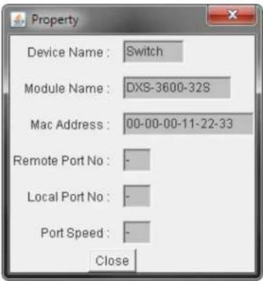
Figure 4-70 Property Window
The fields that can be displayed are described below:
| Parameter Description | |
| Device Name | Display the Device Name of the switches in the SIM group configured by the user. If no Device Name is configured by the name, it will be given the name default and tagged with the last six digits of the MAC Address to identify it. |
| Module Name | Display the full module name of the switch that was right-clicked. |
| MAC Address | Display the MAC Address of the corresponding Switch. |
| Remote Port No | Display the number of the physical port on the MS or CaS that the CS is connected to. The CS will have no entry in this field. |
| Local Port No | Display the number of the physical port on the CS that the MS or CaS is connected to. The CS will have no entry in this field. |
| Port Speed | Display the connection speed between the CS and the MS or CaS. |
Click the Close button to close the property window.
Commander Switch Icon
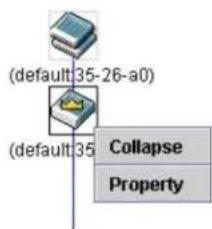
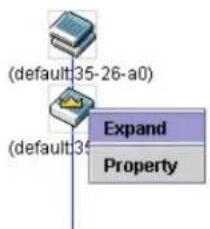
flowchart
graph TD
    A["(default:35-26-a0)"] --> B["(default:35"]
    B --> C["Expand"]
    B --> D["Property"]
Figure 4-71 Right-clicking a Commander Icon
The following options may appear for the user to configure:
- Collapse - To collapse the group that will be represented by a single icon.
- Expand - To expand the SIM group, in detail.
• Property - To pop up a window to display the group information.
Member Switch Icon
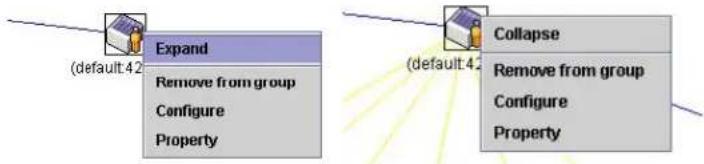
flowchart
graph TD
    A["Expand"] --> B["Remove from group"]
    B --> C["Configure"]
    B --> D["Property"]
    E["Collapse"] --> F["Remove from group"]
    F --> G["Configure"]
    F --> H["Property"]
Figure 4-72 Right-clicking a Member icon
The following options may appear for the user to configure:
- Collapse - To collapse the group that will be represented by a single icon.
- Expand - To expand the SIM group, in detail.
- Remove from group - Remove a member from a group.
- Configure - Launch the web management to configure the Switch.
• Property - To pop up a window to display the device information.
Candidate Switch Icon
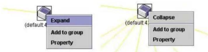
flowchart
graph TD
    A["Expand"] --> B["Add to group"]
    B --> C["Property"]
Figure 4-73 Right-clicking a Candidate icon
The following options may appear for the user to configure:
- Collapse - To collapse the group that will be represented by a single icon.
- Expand - To expand the SIM group, in detail.
- Add to group - Add a candidate to a group. Clicking this option will reveal the following dialog box for the user to enter a password for authentication from the Candidate Switch before being added to the SIM group. Click OK to enter the password or Cancel to exit the dialog box.
Figure 4-74 Input password Window
• Property - To pop up a window to display the device information.
Menu Bar
The Single IP Management window contains a menu bar for device configurations, as seen below.

Figure 4-75 Menu Bar of the Topology View
File
• Print Setup - Will view the image to be printed.
• Print Topology - Will print the topology map.
- Preference - Will set display properties, such as polling interval, and the views to open at SIM startup.
Group
- Add to group - Add a candidate to a group. Clicking this option will reveal the following dialog box for the user to enter a password for authentication from the Candidate Switch before being added to the SIM group. Click OK to enter the password or Cancel to exit the dialog box.
Figure 4-76 Input password Window
- Remove from group - Remove an MS from the group.
Device
- Configure - Will open the Web manager for the specific device.
View
- Refresh - Update the views with the latest status.
• Topology - Display the Topology view.
Help
- About - Will display the SIM information, including the current SIM version.
Figure 4-77 About Window
Firmware Upgrade
This window is used to view and upgrade firmware from the Commander Switch to the Member Switch. Member Switches will be listed in the table
To view the following window, click Management > Virtual Stacking (SIM) > Firmware Upgrade, as shown below:

Figure 4-78 Firmware Upgrade Window
The fields that can be configured in Firmware Upgrade are described below:
| Parameter Description | |
| TFTP Server IP | Enter the TFTP server IP address. |
| Path \ Filename | Enter the path and file name. |
Click the Download button to update the firmware.
To specify a certain switch for firmware download, tick its corresponding check box.
Configuration File Backup/Restore
This window is used to view and upgrade configuration files from the Commander Switch to the Member Switch using a TFTP server. Member Switches will be listed in the table.
To view the following window, click Management > Virtual Stacking (SIM) > Configuration File Backup/Restore, as shown below:

Figure 4-79 Configuration File Backup/Restore Window
The fields that can be configured in Configuration File Backup/Restore are described below:
| Parameter Description | |
| TFTP Server IP | Enter the TFTP server IP address. |
| Path \ Filename | Enter the path and file name. |
Click the Restore button to update the configuration from a TFTP server to the member switch.
Click the Backup button to back up the configuration file to a TFTP server.
Upload Log File
This window is used to view and upload log files from SIM member switches to a specified PC.
To view the following window, click Management > Virtual Stacking (SIM) > Upload Log File, as shown below:

Figure 4-80 Upload Log File Window
The fields that can be configured in Upload Log File are described below:
| Parameter Description | |
| TFTP Server IP | Enter the TFTP server IP address. |
| Path \ Filename | Enter the path and file name. |
Click the Upload button to initiate the file transfer.
SMTP Settings
This window is used to view and configure the Simple Mail Transfer Protocol (SMTP) settings.
To view the following window, click Management > SMTP Settings, as shown below:
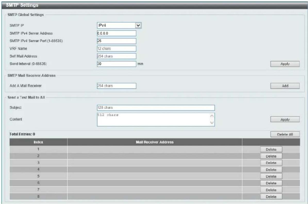
Figure 4-81 SMTP Settings Window
The fields that can be configured in SMTP Global Settings are described below:
| Parameter Description | |
| SMTP IP | Select the SMTP server's IP address type here. Options to choose from are IPv4 and IPv6. |
| SMTP IPv4 Server Address | After selecting IPv4 as the SMTP IP type enter the SMTP server's IPv4 address here. |
| SMTP IPv6 Server Address | After selecting IPv6 as the SMTP IP type enter the SMTP server's IPv6 address here. |
| SMTP IPv4 Server Port | After selecting IPv4 as the SMTP IP type enter the SMTP server's port number here. The range is from 1 to 65535. By default, this value is 25. |
| SMTP IPv6 Server Port | After selecting IPv6 as the SMTP IP type enter the SMTP server's port number here. The range is from 1 to 65535. By default, this value is 25. |
| VRF Name | Enter the VRF instance's name that will be used here. This name can be up to 12 characters long. This option is only available when IPv4 was selected as the SMTP IP type. |
| Self Mail Address | Enter the email address that represents the switch here. This string can be up to 254 characters long. |
| Send Interval | Enter the sending interval value here. The range is from 0 to 65535 minutes. By default, this value is 30 minutes. |
Click the Apply button to accept the changes made.
The fields that can be configured in SMTP Mail Receiver Address are described below:
| Parameter Description | |
| Add A Mail Receiver | Enter the email address of the receiver here. This string can be up to 254 characters long. |
Click the Add button to add a new SMTP email recipient.
The fields that can be configured in Send a Test Mail to All are described below:
| Parameter Description | |
| Subject | Enter the subject of the email here. This string can be up to 128 characters long. |
| Content | Enter the content of the email here. This string can be up to 512 characters long. |
Click the Apply button to accept the changes made.
Click the Delete All button to delete all the entries found in the display table.
Click the Delete button to delete the specified entry.
NLB FDB Settings
This window is used to view and configure the Network Load Balancing (NLB) FDB settings.
The Network Load Balancing (NLB) function is used to support the Microsoft server load balancing application where multiple servers can share the same IP address and MAC address. The requests from
clients will be forwarded to all the servers, but will only be processed by one of them. The server can work in two different modes:
- Unicast mode: The client uses a unicast MAC address as the destination MAC address to reach the server.
- Multicast mode: The client uses a multicast MAC address as the destination MAC address to reach the server.
This destination MAC address is called the shared MAC address. However, the server uses its own MAC address (rather than the shared MAC address) as the source MAC address in the reply packet. In other words, a NLB unicast address usually is not the source MAC address of a packet.
When the received packet contains the destination MAC address matches the configured unicast MAC address, it will be forwarded to those configured ports, regardless of the VLAN membership configuration.
Administrators cannot configure a static address of the MAC address table as a NLB address. However, if a MAC address is created as a NLB MAC address entry, the same MAC address can be still dynamically learnt in the Layer 2 MAC address table. In this situation, the NLB has higher priority; the dynamically learnt FDB entry won't take effect.
To view the following window, click Management > NLB FDB Settings, as shown below:
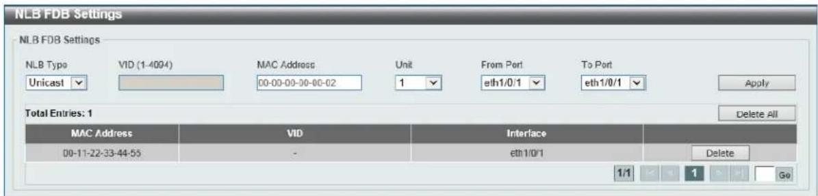
Figure 4-82 NLB FDB Settings Window
The fields that can be configured in NLB FDB Settings are described below:
| Parameter Description | |
| NLB Type | Select the NLB type here. Options to choose from are Unicast and Multicast. |
| VID | After selecting Multicast as the NLB type, enter the VLAN ID used in this configuration here. |
| MAC Address | Enter the unicast or multicast MAC address of the entry here. If a received packet contains a destination MAC address that matches the specified MAC address, it will be forwarded to the specified interface. |
| Unit | Select the switch's unit ID that will be used here. |
| From Port ~ To Port | Select the switch's port range that will be used here. |
Click the Apply button to accept the changes made.
Click the Delete All button to delete all the entries found in the display table.
Click the Delete button to delete the specified entry.
5. Layer 2 Features
FDB
VLAN
VLAN Tunnel
STP
ERPS (G.8032)
Loopback Detection
Link Aggregation
L2 Protocol Tunnel
L2 Multicast Control
LLDP
FDB
Static FDB
Unicast Static FDB
This window is used to view and configure the static unicast forwarding settings on the switch.
To view the following window, click L2 Features > FDB > Static FDB > Unicast Static FDB, as shown below:
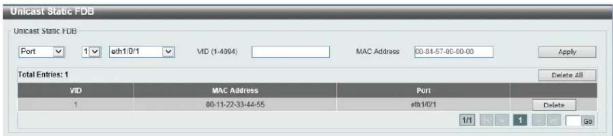
Figure 5-1 Unicast Static FDB Window
The fields that can be configured are described below:
| Parameter Description | |
| Port/Drop | Allows the selection of the port number on which the MAC address entered resides This option could also drop the MAC address from the unicast static FDB. When selecting Port, select the port number. |
| Unit | Select the stacking unit ID of the switch that will be configured here. |
| Port Number | After selecting the Port option, select the port number used here. |
| VID | Enter the VLAN ID on which the associated unicast MAC address resides. |
| MAC Address | Enter the MAC address to which packets will be statically forwarded. This must be a unicast MAC address. |
Click the Apply button to accept the changes made.
Click the Delete All button to delete all the entries found in the display table.
Click the Delete button to delete the specified entry.
Multicast Static FDB
This window is used to view and configure the multicast static FDB settings.
To view the following window, click L2 Features > FDB > Static FDB > Multicast Static FDB, as shown below:
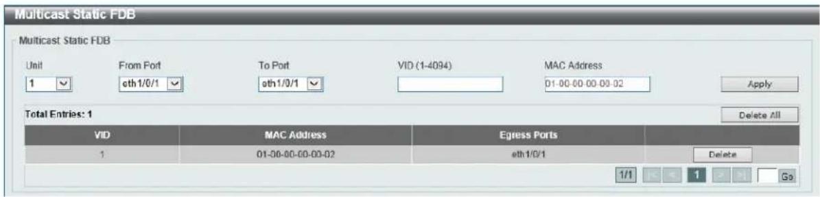
Figure 5-2 Multicast Static FDB Window
The fields that can be configured are described below:
| Parameter Description | |
| Unit | Select the stacking unit ID of the switch that will be configured here. |
| From Port ~ To Port | Select the range of ports that will be used for this configuration here. |
| VID | Enter the VLAN ID of the VLAN the corresponding MAC address belongs to. |
| MAC Address | Enter the static destination MAC address of the multicast packets. This must be a multicast MAC address. The format of the destination MAC address is 01-XX-XX-XX-XX-XX. |
Click the Apply button to accept the changes made.
Click the Delete All button to remove all the entries.
Click the Delete button to remove the specific entry.
MAC Address Table Settings
This window is used to view and configure the MAC address table's global settings.
To view the following window, click L2 Features > FDB > MAC Address Table Settings, as shown below:

Figure 5-3 MAC Address Table Settings (Global Settings) Window
The fields that can be configured are described below:
| Parameter Description | |
| Aging Time | Enter the MAC address table's aging time value here. This value must be between 10 and 1000000 seconds. Entering 0 will disable MAC address aging. By default, this value is 300 seconds. |
| Aging Destination Hit | Select to enable or disable the aging destination hit function. |
Click the Apply button to accept the changes made.
After selecting the MAC Address Learning tab option, at the top of the page, the following page will be available.
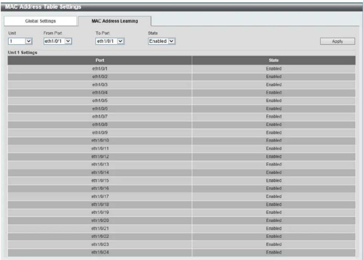
Figure 5-4 MAC Address Table Settings (MAC Address Learning) Window
The fields that can be configured are described below:
| Parameter Description | |
| Unit | Select the stacking unit ID of the switch that will be configured here. |
| From Port ~ To Port | Select the range of ports that will be used for this configuration here. |
| State | Select to enable or disable the MAC address learning function on the ports specified here. |
Click the Apply button to accept the changes made.
MAC Address Table
This window is used to view the entries listed in the MAC address table.
To view the following window, click L2 Features > FDB > MAC Address Table, as shown below:
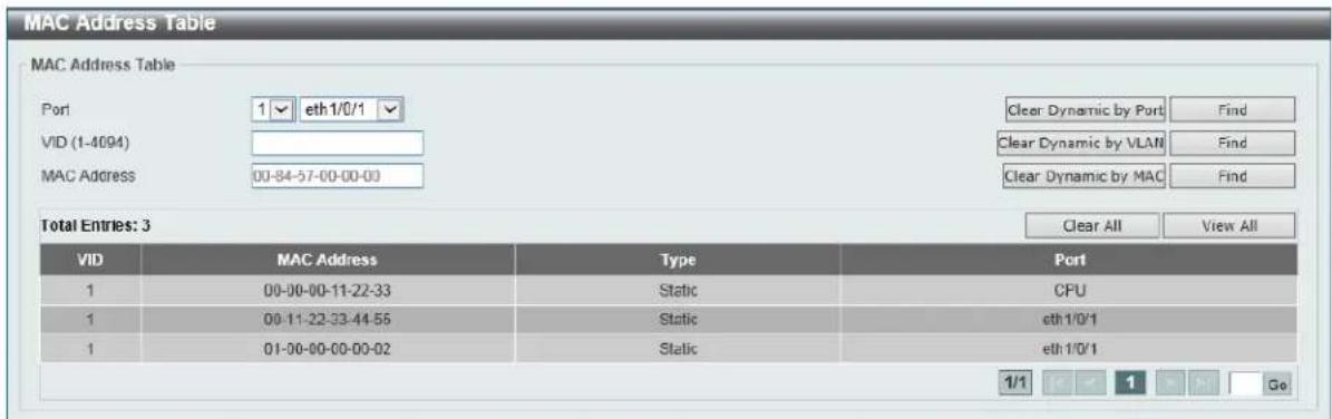
Figure 5-5 MAC Address Table Window
The fields that can be configured are described below:
| Parameter Description | |
| Port | Select the stacking unit ID and the port number of the switch that will be configured here. |
| VID | Enter the VLAN ID that will be used for this configuration here. |
| MAC Address | Enter the MAC address that will be used for this configuration here. |
Click the Apply button to accept the changes made.
Click the Clear Dynamic by Port button to clear the dynamic MAC address listed on the corresponding port.
Click the Clear Dynamic by VLAN button to clear the dynamic MAC address listed on the corresponding VLAN.
Click the Clear Dynamic by MAC button to clear the dynamic MAC address entered.
Click the Find button to locate a specific entry based on the information entered.
Click the Clear All button to clear all dynamic MAC addresses.
Click the View All button to display all the MAC addresses recorded in the MAC address table.
MAC Notification
This window is used to view and configure MAC notification.
To view the following window, click L2 Features > FDB > MAC Notification, as shown below:
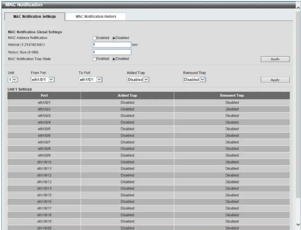
Figure 5-6 MAC Notification (MAC Notification Settings) Window
The fields that can be configured are described below:
| Parameter Description | |
| MAC Address Notification | Select to enable or disable MAC notification globally on the switch |
| Interval | Enter the time value between notifications. This value must be between 1 and 2147483647 seconds. By default, this value is 1 second. |
| History Size | Enter the maximum number of entries listed in the history log used for notification. This value must be between 0 and 500. By default, this value is 1. |
| MAC Notification Trap State | Select to enable or disable the MAC notification trap state. |
| Unit | Select the stacking unit ID of the switch that will be configured here. |
| From Port ~ To Port | Select the range of ports that will be used for this configuration here. |
| Added Trap | Select to enable or disable the added trap for the port(s) selected. |
| Removed Trap | Select to enable or disable the removed trap for the port(s) selected. |
Click the Apply button to accept the changes made for each individual section.
After selecting the MAC Notification History tab, at the top of the page, the following page will be available.

Figure 5-7 MAC Notification (MAC Notification History) Window
On this page, a list of MAC notification messages will be displayed.
VLAN
802.1Q VLAN
This window is used to view and configure the VLAN settings on this switch.
To view the following window, click L2 Features > VLAN > 802.1Q VLAN, as shown below:
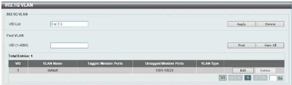
Figure 5-8 802.1Q VLAN Window
The fields that can be configured are described below:
| Parameter Description | |
| VID List | Enter the VLAN ID list that will be created here. |
| VID | Enter the VLAN ID that will be displayed here. |
Click the Apply button to accept the changes made.
Click the Delete button to remove the specific entry.
Click the Find button to locate a specific entry based on the information entered.
Click the View All button to locate all the entries.
Click the Edit button to re-configure the specific entry.
802.1v Protocol VLAN
Protocol VLAN Profile
This window is used to view and configure 802.1v protocol VLAN profiles. The 802.1v Protocol VLAN Group Settings support multiple VLANs for each protocol and allows the user to configure the untagged ports of different protocols on the same physical port. For example, it allows the user to configure an 802.1Q and 802.1v untagged port on the same physical port.
To view the following window, click L2 Features > VLAN > 802.1v Protocol VLAN > Protocol VLAN Profile, as shown below:

Figure 5-9 Protocol VLAN Profile Window
The fields that can be configured are described below:
| Parameter Description | |
| Profile ID | Enter the 802.1v protocol VLAN profile ID here. This value must be between 1 and 16. |
| Frame Type | Select the frame type option here. This function maps packets to protocol-defined VLANs by examining the type octet within the packet header to discover the type of protocol associated with it. Options to choose from are Ethernet 2, SNAP, and LLC. |
| Ether Type | Enter the Ethernet type value for the group here. The protocol value is used to identify a protocol of the frame type specified. The form of the input is 0x0 to 0xFFFF. Depending on the frame type, the octet string will have one of the following values:For Ethernet 2, this is a 16-bit (2-octet) hex value. For example, IPv4 is 0800, IPv6 is 86DD, ARP is 0806, etc...For IEEE802.3 SNAP, this is a 16-bit (2-octet) hex value.For IEEE802.3 LLC, this is a 2-octet IEEE 802.2 Link Service Access Point (LSAP) pair. The first octet is for Destination Service Access Point (DSAP) and the second octet is for Source. |
Click the Apply button to accept the changes made.
Click the Delete button to remove the specific entry.
Protocol VLAN Profile Interface
This window is used to view and configure the protocol VLAN profile's interface settings.
To view the following window, click L2 Features > VLAN > 802.1v Protocol VLAN > Protocol VLAN Profile Interface, as shown below:

Figure 5-10 Protocol VLAN Profile Interface Window
The fields that can be configured are described below:
| Parameter Description | |
| Port | Select the stacking unit ID and the port number of the switch that willbe configured here. |
| Profile ID | Select the 802.1v protocol VLAN profile ID here. |
| VID | Enter the VLAN ID used here. |
| Priority | Select the priority value used here. This value is between 0 and 7. This parameter is specified to re-write the 802.1p default priority previously set in the switch, which is used to determine the CoS queue to which packets are forwarded to. Once this field is specified, packets accepted by the switch that match this priority are forwarded to the CoS queue specified previously by the user. |
Click the Apply button to accept the changes made.
Click the Delete button to remove the specific entry.
GVRP
GVRP Global
This window is used to view and configure the GARP VLAN Registration Protocol (GVRP) global settings.
To view the following window, click L2 Features > VLAN > GVRP > GVRP Global, as shown below:

Figure 5-11 GVRP Global Window
The fields that can be configured are described below:
| Parameter Description | |
| Global GVRP State | Select to enable or disable the global GVRP state here. |
| Dynamic VLAN Creation | Select to enable or disable the dynamic VLAN creation function here. |
| NNI BPDU Address | Select the NNI BPDU address option here. This option is used to determine the BPDU protocol address for GVRP in service provide site. It can use 802.1d GVRP address or 802.1ad service provider GVRP address. Options to choose from are Dot1d and Dot1ad. |
Click the Apply button to accept the changes made.
GVRP Port
This window is used to view and configure the GVRP port settings.
To view the following window, click L2 Features > VLAN > GVRP > GVRP Port, as shown below:
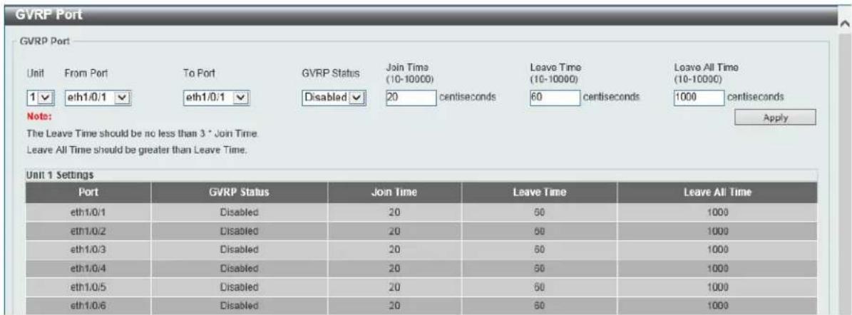
Figure 5-12 GVRP Port Window
The fields that can be configured are described below:
| Parameter Description | |
| Unit | Select the switch unit that will be used for this configuration here. |
| From Port ~ To Port | Select the range of ports that will be used for this configuration here. |
| GVRP Status | Select the enable or disable the GVRP port status. This enables the port to dynamically become a member of a VLAN. By default, this option is disabled. |
| Join Time | Enter the Join Time value in centiseconds. This value must be between 10 and 10000 centiseconds. By default, this value is 20 centiseconds. |
| Leave Time | Enter the Leave Time value in centiseconds. This value must be between 10 and 10000 centiseconds. By default, this value is 60 centiseconds. |
| Leave All Time | Enter the Leave All Time value in centiseconds. This value must be between 10 and 10000 centiseconds. By default, this value is 1000 centiseconds. |
Click the Apply button to accept the changes made.
GVRP Advertise VLAN
This window is used to view and configure the GVRP advertised VLAN settings.
To view the following window, click L2 Features > VLAN > GVRP > GVRP Advertise VLAN, as shown below:
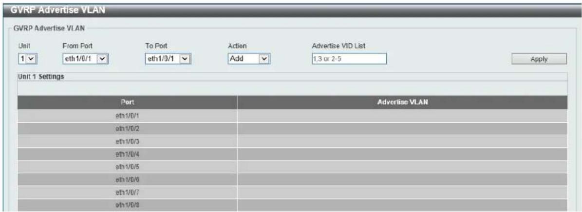
Figure 5-13 GVRP Advertise VLAN Window
The fields that can be configured are described below:
| Parameter Description | |
| Unit | Select the switch unit that will be used for this configuration here. |
| From Port ~ To Port | Select the range of ports that will be used for this configuration here. |
| Action | Select the advertised VLAN to port mapping action that will be taken here. Options to choose from are All, Add, Remove, and Replace. When selecting All, all the advertised VLANs will be used. |
| Advertise VID List | Enter the advertised VLAN ID list here. |
Click the Apply button to accept the changes made.
GVRP Forbidden VLAN
This window is used to view and configure the GVRP forbidden VLAN settings.
To view the following window, click L2 Features > VLAN > GVRP > GVRP Forbidden VLAN, as shown below:
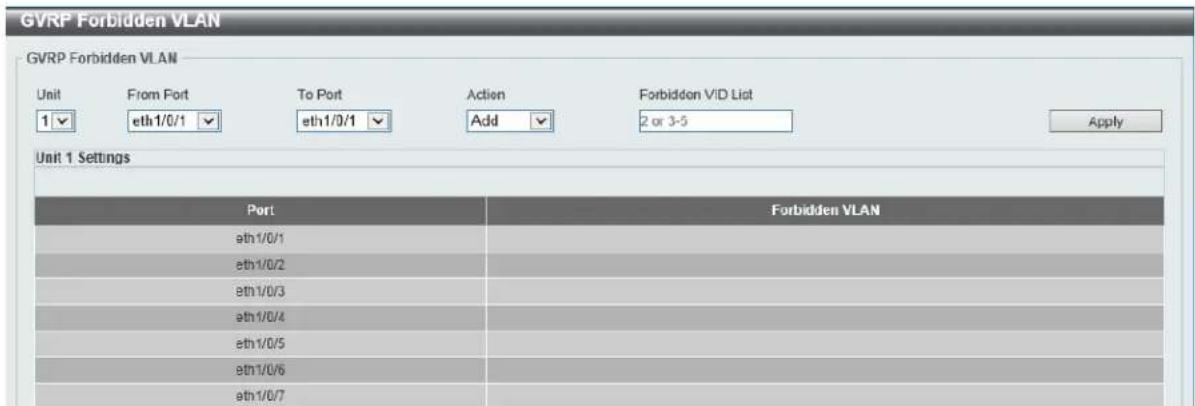
Figure 5-14 GVRP Forbidden VLAN Window
The fields that can be configured are described below:
| Parameter Description | |
| Unit | Select the switch unit that will be used for this configuration here. |
| From Port ~ To Port | Select the range of ports that will be used for this configuration here. |
| Action | Select the forbidden VLAN to port mapping action that will be taken here. Options to choose from are All, Add, and Remove. When selecting All, all the forbidden VLANs will be used. |
| Forbidden VID List | Enter the forbidden VLAN ID list here. |
Click the Apply button to accept the changes made.
GVRP Statistics Table
This window is used to view GVRP statistics information.
To view the following window, click L2 Features > VLAN > GVRP > GVRP Statistics Table, as shown below:
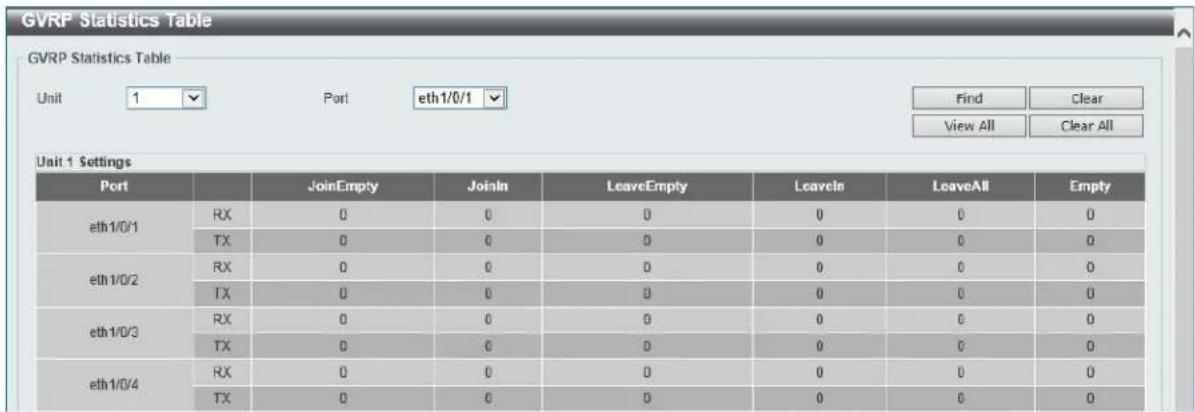
Figure 5-15 GVRP Statistics Table Window
The fields that can be configured are described below:
| Parameter Description | |
| Unit | Select the switch unit that will be used for this display here. |
| Port | Select the port number of which GVRP statistic information will be displayed. |
Click the Find button to locate a specific entry based on the information entered.
Click the Clear button to clear all the information for the specific port.
Click the View All button to view all GVRP statistic information.
Click the Clear All button to clear all the information in this table.
MAC VLAN
This window is used to view and configure the MAC-based VLAN information. When a static MAC-based VLAN entry is created for a user, the traffic according to the specified VLAN operating on this port will be configured.
To view the following window, click L2 Features > VLAN > MAC VLAN, as shown below:
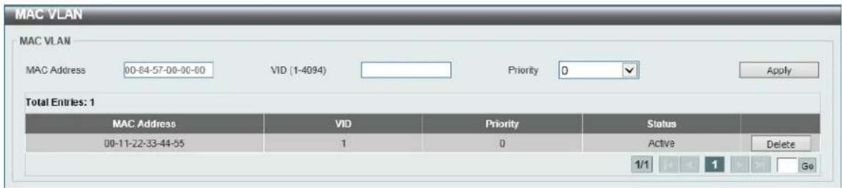
Figure 5-16 MAC VLAN Window
The fields that can be configured are described below:
| Parameter Description | |
| MAC Address | Enter the unicast MAC address. |
| VID | Enter the VLAN ID that will be used. |
| Priority | Select the priority that is assigned to untagged packets. This value is between 0 and 7. |
Click the Apply button to accept the changes made.
Click the Delete button to remove the specific entry.
VLAN Interface
This window is used to view and configure VLAN interface settings.
To view the following window, click L2 Features > VLAN > VLAN Interface, as shown below:
| Port | VLAN Mode | Ingress Checking | Acceptable Frame Type | |||
| eth1/0/1 | Hybrid | Enabled | Admit-All | VLAN Detail | Edit | |
| eth1/0/2 | Hybrid | Enabled | Admit-All | VLAN Detail | Edit | |
| eth1/0/3 | Hybrid | Enabled | Admit-All | VLAN Detail | Edit | |
| eth1/0/4 | Hybrid | Enabled | Admit-All | VLAN Detail | Edit | |
| eth1/0/5 | Hybrid | Enabled | Admit-All | VLAN Detail | Edit | |
| eth1/0/6 | Hybrid | Enabled | Admit-All | VLAN Detail | Edit | |
| eth1/0/7 | Hybrid | Enabled | Admit-All | VLAN Detail | Edit | |
| eth1/0/8 | Hybrid | Enabled | Admit-All | VLAN Detail | Edit | |
| eth1/0/9 | Hybrid | Enabled | Admit-All | VLAN Detail | Edit | |
| eth 1/0/10 | Hybrid | Enabled | Admit-All | VLAN Detail | Edit | |
| eth 1/0/11 | Hybrid | Enabled | Admit-All | VLAN Detail | Edit | |
| eth 1/0/12 | Hybrid | Enabled | Admit-All | VLAN Detail | Edit | |
| eth 1/0/13 | Hybrid | Enabled | Admit-All | VLAN Detail | Edit | |
| eth 1/0/14 | Hybrid | Enabled | Admit-All | VLAN Detail | Edit | |
| eth 1/0/15 | Hybrid | Enabled | Admit-All | VLAN Detail | Edit | |
| eth 1/0/16 | Hybrid | Enabled | Admit-All | VLAN Detail | Edit | |
| eth 1/0/17 | Hybrid | Enabled | Admit-All | VLAN Detail | Edit | |
| eth 1/0/18 | Hybrid | Enabled | Admit-All | VLAN Detail | Edit | |
| eth 1/0/19 | Hybrid | Enabled | Admit-All | VLAN Detail | Edit | |
| eth 1/0/20 | Hybrid | Enabled | Admit-All | VLAN Detail | Edit | |
| eth 1/0/21 | Hybrid | Enabled | Admit-All | VLAN Detail | Edit | |
| eth 1/0/22 | Hybrid | Enabled | Admit-All | VLAN Detail | Edit | |
| eth 1/0/23 | Hybrid | Enabled | Admit-All | VLAN Detail | Edit | |
| eth 1/0/24 | Hybrid | Enabled | Admit-All | VLAN Detail | Edit | |
Figure 5-17 VLAN Interface Window
The fields that can be configured are described below:
| Parameter Description | |
| Unit | Select the switch unit that will be used for this configuration here. |
Click the View Detail button to view more detailed information about the VLAN on the specific interface.
Click the Edit button to re-configure the specific entry.
After clicking the VLAN Detail button, the following page will appear.
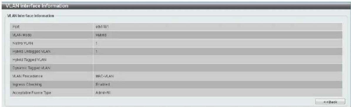
Figure 5-19 VLAN Interface (Access) Window
The fields that can be configured are described below:
| Parameter Description | |
| VLAN Mode | Select the VLAN mode option here. Options to choose from are Access, Hybrid, Trunk, 802.1Q-Tunnel, Promiscuous, Host, Trunk Promiscuous, and Trunk Secondary. |
| Acceptable Frame | Select the acceptable frame behavior option here. Options to choose from are Tagged Only, Untagged Only, and Admit All. |
| Ingress Checking | Select to enable or disable the ingress checking function. |
| VLAN ID | Enter the VLAN ID used for this configuration here. This value must bebetween 1 and 4094. |
| Clone | Select this option to enable the clone feature. |
| From Port ~ To Port | Select the range of ports that will be used in the clone feature here. |
Click the Apply button to accept the changes made.
Click the Back button to discard the changes made and return to the previous page.
When Hybrid was selected as the VLAN Mode, the following page will appear.
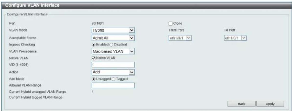
Figure 5-20 VLAN Interface (Hybrid) Window
The fields that can be configured are described below:
| Parameter Description | |
| VLAN Mode | Select the VLAN mode option here. Options to choose from are Access, Hybrid, Trunk, 802.1Q-Tunnel, Promiscuous, Host, Trunk Promiscuous, and Trunk Secondary. |
| Acceptable Frame | Select the acceptable frame behavior option here. Options to choose from are Tagged Only, Untagged Only, and Admit All. |
| Ingress Checking | Select to enable or disable the ingress checking function. |
| VLAN Precedence | Select the VLAN precedence option here. Options to choose from are Mac-based VLAN and Subnet-based VLAN. |
| Native VLAN | Tick this option to enable the native VLAN function. |
| VID | After ticking the Native VLAN option the following parameter will be available. Enter the VLAN ID used for this configuration here. This value must be between 1 and 4094. |
| Action | Select the action that will be taken here. Options to choose from are Add, Remove, Tagged, and Untagged. |
| Add Mode | Select whether to add an Untagged or Tagged parameters. |
| Allowed VLAN Range | Enter the allowed VLAN range information here. |
| Clone | Select this option to enable the clone feature. |
| From Port ~ To Port | Select the range of ports that will be used in the clone feature here. |
Click the Apply button to accept the changes made.
Click the Back button to discard the changes made and return to the previous page.
When Trunk was selected as the VLAN Mode, the following page will appear.
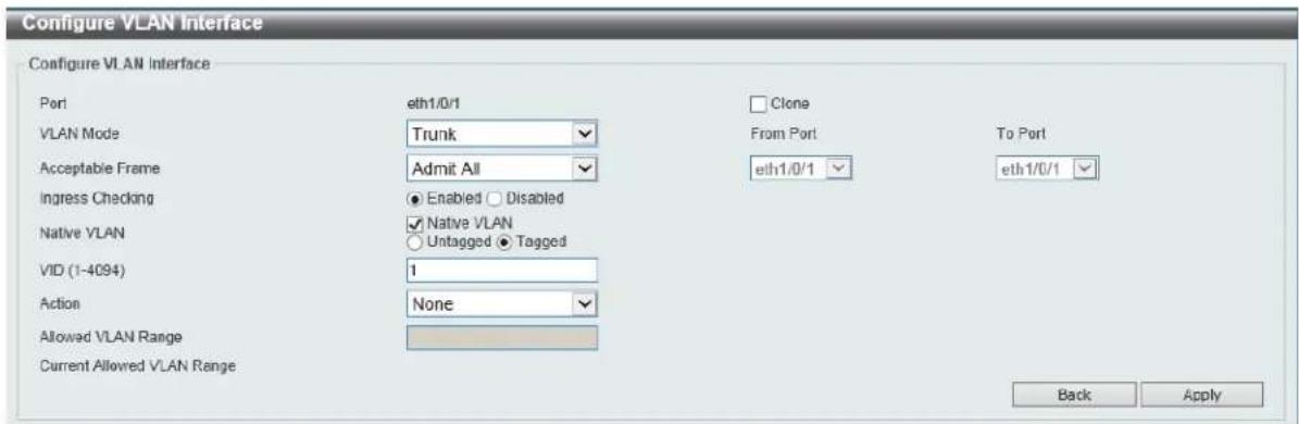
Figure 5-21 VLAN Interface (Trunk) Window
The fields that can be configured are described below:
| Parameter Description | |
| VLAN Mode | Select the VLAN mode option here. Options to choose from are Access, Hybrid, Trunk, 802.1Q-Tunnel, Promiscuous, Host, Trunk Promiscuous, and Trunk Secondary. |
| Acceptable Frame | Select the acceptable frame behavior option here. Options to choose from are Tagged Only, Untagged Only, and Admit All. |
| Ingress Checking | After selecting Trunk as the VLAN Mode the following parameter will be available. Select to enable or disable the ingress checking function. |
| Native VLAN | Tick this option to enable the native VLAN function. Also select if this VLAN supports Untagged or Tagged frames. |
| VID | After ticking the Native VLAN option the following parameter will be available. Enter the VLAN ID used for this configuration here. This value must be between 1 and 4094. |
| Action | Select the action that will be taken here. Options to choose from are All, Add, Remove, Except, and Replace. |
| Allowed VLAN Range | Enter the allowed VLAN range information here. |
| Clone | Select this option to enable the clone feature. |
| From Port ~ To Port | Select the range of ports that will be used in the clone feature here. |
Click the Apply button to accept the changes made.
Click the Back button to discard the changes made and return to the previous page.
When 802.1Q-Tunnel was selected as the VLAN Mode, the following page will appear.
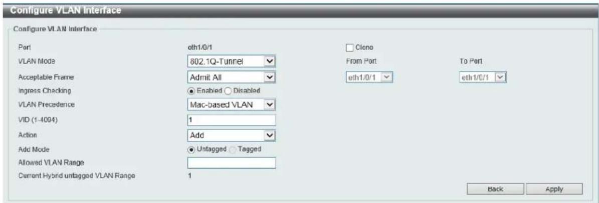
Figure 5-22 VLAN Interface (802.1Q-Tunnel) Window
The fields that can be configured are described below:
| Parameter Description | |
| VLAN Mode | Select the VLAN mode option here. Options to choose from are Access, Hybrid, Trunk, 802.1Q-Tunnel, Promiscuous, Host, Trunk Promiscuous, and Trunk Secondary. |
| Acceptable Frame | Select the acceptable frame behavior option here. Options to choose from are Tagged Only, Untagged Only, and Admit All. |
| Ingress Checking | Select to enable or disable the ingress checking function. |
| VLAN Precedence | Select the VLAN precedence option here. Options to choose from are Mac-based VLAN and Subnet-based VLAN. |
| VID | Enter the VLAN ID used for this configuration here. This value must be between 1 and 4094. |
| Action | Select Add to add a new entry based in the information entered. Select Remove to remove an entry based in the information entered. |
| Add Mode | Select to add an Untagged parameter. |
| Allowed VLAN Range | Enter the allowed VLAN range information here. |
| Clone | Select this option to enable the clone feature. |
| From Port ~ To Port | Select the range of ports that will be used in the clone feature here. |
Click the Apply button to accept the changes made.
Click the Back button to discard the changes made and return to the previous page.
When Promiscuous was selected as the VLAN Mode, the following page will appear.
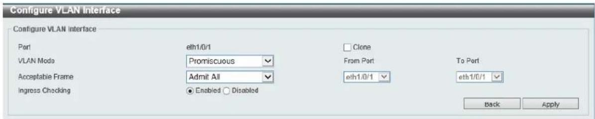
Figure 5-23 VLAN Interface (Promiscuous) Window
The fields that can be configured are described below:
| Parameter Description | |
| VLAN Mode | Select the VLAN mode option here. Options to choose from are Access, Hybrid, Trunk, 802.1Q-Tunnel, Promiscuous, Host, Trunk Promiscuous, and Trunk Secondary. |
| Acceptable Frame | Select the acceptable frame behavior option here. Options to choose from are Tagged Only, Untagged Only, and Admit All. |
| Ingress Checking | Select to enable or disable the ingress checking function. |
| Clone | Select this option to enable the clone feature. |
| From Port ~ To Port | Select the range of ports that will be used in the clone feature here. |
Click the Apply button to accept the changes made.
Click the Back button to discard the changes made and return to the previous page.
When Host was selected as the VLAN Mode, the following page will appear.

Figure 5-24 VLAN Interface (Host) Window
The fields that can be configured are described below:
| Parameter Description | |
| VLAN Mode | Select the VLAN mode option here. Options to choose from are Access, Hybrid, Trunk, 802.1Q-Tunnel, Promiscuous, Host, Trunk Promiscuous, and Trunk Secondary. |
| Acceptable Frame | Select the acceptable frame behavior option here. Options to choose from are Tagged Only, Untagged Only, and Admit All. |
| Ingress Checking | Select to enable or disable the ingress checking function. |
| Clone | Select this option to enable the clone feature. |
| From Port ~ To Port | Select the range of ports that will be used in the clone feature here. |
Click the Apply button to accept the changes made.
Click the Back button to discard the changes made and return to the previous page.
When Trunk Promiscuous was selected as the VLAN Mode, the following page will appear.
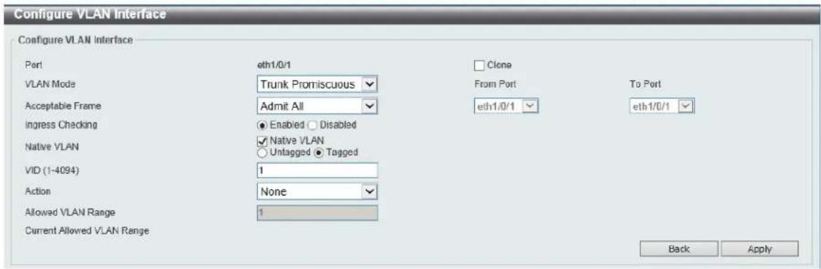
Figure 5-25 VLAN Interface (Trunk Promiscuous) Window
The fields that can be configured are described below:
| Parameter Description | |
| VLAN Mode | Select the VLAN mode option here. Options to choose from are Access, Hybrid, Trunk, 802.1Q-Tunnel, Promiscuous, Host, Trunk Promiscuous, and Trunk Secondary. |
| Acceptable Frame | Select the acceptable frame behavior option here. Options to choose from are Tagged Only, Untagged Only, and Admit All. |
| Ingress Checking | After selecting Trunk Promiscuous as the VLAN Mode the following parameter will be available. Select to enable or disable the ingress checking function. |
| Native VLAN | Tick this option to enable the native VLAN function. Also select if this VLAN supports Untagged or Tagged frames. |
| VID | After ticking the Native VLAN option the following parameter will be available. Enter the VLAN ID used for this configuration here. This value must be between 1 and 4094. |
| Action | Select the action that will be taken here. Options to choose from are All, Add, Remove, Except, and Replace. |
| Allowed VLAN Range | Enter the allowed VLAN range information here. |
| Clone | Select this option to enable the clone feature. |
| From Port ~ To Port | Select the range of ports that will be used in the clone feature here. |
Click the Apply button to accept the changes made.
Click the Back button to discard the changes made and return to the previous page.
When Trunk Secondary was selected as the VLAN Mode, the following page will appear.
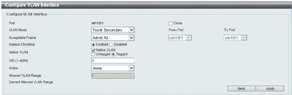
Figure 5-26 VLAN Interface (Trunk Secondary) Window
The fields that can be configured are described below:
| Parameter Description | |
| VLAN Mode | Select the VLAN mode option here. Options to choose from are Access, Hybrid, Trunk, 802.1Q-Tunnel, Promiscuous, Host, Trunk Promiscuous, and Trunk Secondary. |
| Acceptable Frame | Select the acceptable frame behavior option here. Options to choose from are Tagged Only, Untagged Only, and Admit All. |
| Ingress Checking | After selecting Trunk Secondary as the VLAN Mode the following parameter will be available. Select to enable or disable the ingress checking function. |
| Native VLAN | Tick this option to enable the native VLAN function. Also select if this VLAN supports Untagged or Tagged frames. |
| VID | After ticking the Native VLAN option the following parameter will be available. Enter the VLAN ID used for this configuration here. This value must be between 1 and 4094. |
| Action | Select the action that will be taken here. Options to choose from are All, Add, Remove, Except, and Replace. |
| Allowed VLAN Range | Enter the allowed VLAN range information here. |
| Clone | Select this option to enable the clone feature. |
| From Port ~ To Port | Select the range of ports that will be used in the clone feature here. |
Click the Apply button to accept the changes made.
Click the Back button to discard the changes made and return to the previous page.
Subnet VLAN
This window is used to view and configure the subnet VLAN settings. A subnet VLAN entry is an IP subnet-based VLAN classification rule. If an untagged or priority-tagged IP packet is received on a port, its source IP address will be used to match the subnet VLAN entries. If the source IP is in the subnet of an entry, the packet will be classified to the VLAN defined for this subnet.
To view the following window, click L2 Features > VLAN > Subnet VLAN, as shown below:
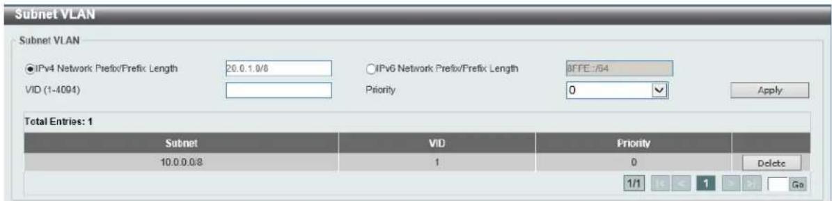
Figure 5-27 Subnet VLAN Window
The fields that can be configured are described below:
| Parameter Description | |
| IPv4 Network Prefix / Prefix Length | Select and enter the IPv4 address and prefix length value for the subnet VLAN here. |
| IPv6 Network Prefix / Prefix Length | Select and enter the IPv6 address and prefix length value for the subnet VLAN here. |
| VID | Enter the VLAN ID for the subnet VLAN here. |
| Priority | Select the priority value used here. This value is between 0 and 7. A lower value takes higher priority. |
Click the Apply button to accept the changes made.
Click the Delete button to remove the specific entry.
Super VLAN
This window is used to view and configure the super VLAN settings. Super VLANs are used to aggregate multiple sub-VLANs (Layer 2 broadcast domains) into IP subnets. A super VLAN cannot have any physical member port. A super VLAN cannot be a sub-VLAN at the same time. Once an IP interface is bound to a super VLAN, the proxy ARP will be enabled automatically on the interface for communication between its sub-VLANs. Multiple super VLANs can be configured and each super VLAN can consist of multiple sub-VLANs.
Private VLANs and super VLANs are mutually exclusive. A private VLAN cannot be configured as a super VLAN. Layer 3 routing protocols, VRRP, multicast protocols, and the IPv6 protocol cannot run on a super VLAN interface.
To view the following window, click L2 Features > VLAN > Super VLAN, as shown below:
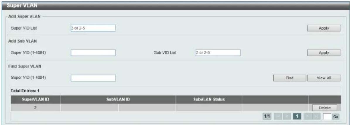
Figure 5-28 Super VLAN Window
The fields that can be configured in Add Super VLAN are described below:
| Parameter Description | |
| Super VID List | Enter the VLAN ID(s) of the VLAN that will be used as a super VLAN here. |
Click the Apply button to accept the changes made.
The fields that can be configured in Add Sub VLAN are described below:
| Parameter Description | |
| Super VID | Enter the super VLAN’s ID here. |
| Sub VID List | Enter the VLAN ID(s) of the VLAN that will be added as a sub-VLAN of the super VLAN here. A sub-VLAN is a Layer 2 broadcast domain. |
Click the Apply button to accept the changes made.
The fields that can be configured in Find Super VLAN are described below:
| Parameter Description | |
| Super VID | Enter the super VLAN's ID here. |
Click the Find button to locate a specific entry based on the information entered.
Click the View All button to display all the entries.
Private VLAN
This window is used to view and configure the private VLAN settings.
To view the following window, click L2 Features > VLAN > Private VLAN, as shown below:
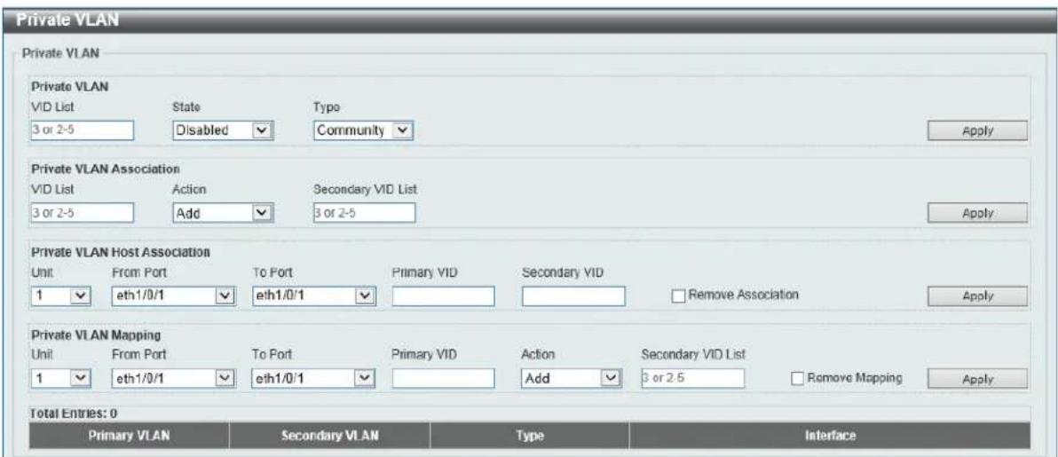
Figure 5-29 Private VLAN Window
The fields that can be configured for Private VLAN are described below:
| Parameter Description | |
| VID List | Enter the private VLAN ID list here. |
| State | Select to enable or disable the private VLAN state here. |
| Type | Select the type of private VLAN that will be created here. Options to choose from areCommunity, Isolated, and Primary. |
Click the Apply button to accept the changes made.
The fields that can be configured for Private VLAN Association are described below:
| Parameter Description | |
| VID List | Enter the private VLAN ID list here. |
| Action | Select the action that will be taken for the private VLAN here. Options to choose from are Add, Remove, and Disabled. |
| Secondary VID List | Enter the secondary private VLAN ID here. |
Click the Apply button to accept the changes made.
The fields that can be configured for Private VLAN Host Association are described below:
| Parameter Description | |
| Unit | Select the switch unit that will be used for this configuration here. |
| From Port ~ To Port | Select the range of ports that will be used for this configuration here. |
| Primary VID | Enter the primary private VLAN ID here. |
| Secondary VID | Enter the secondary private VLAN ID here. When ticking the Remove Association option, specifies that this configuration will not be enabled. |
Click the Apply button to accept the changes made.
The fields that can be configured for Private VLAN Mapping are described below:
| Parameter Description | |
| Unit | Select the switch unit that will be used for this configuration here. |
| From Port ~ To Port | Select the range of ports that will be used for this configuration here. |
| Primary VID | Enter the primary private VLAN ID here. |
| Action | Select Add to add a new entry based in the information entered.Select Remove to remove an entry based in the information entered. |
| Secondary VID List | Enter the secondary private VLAN ID here. When ticking the Remove Mapping option, specifies that this configuration will not be enabled. |
Click the Apply button to accept the changes made.
VLAN Tunnel
Dot1q Tunnel
This window is used to view and configure the 802.1Q VLAN tunnel's settings.
An 802.1Q tunnel port behaves as an UNI port of a service VLAN. The trunk ports which are tagged members of the service VLAN behave as the NNI ports of the service VLAN.
Only configure the 802.1Q tunneling Ethernet type on ports that are connected to the provider bridge network, which receives and transmits the service VLAN tagged frames. If the tunnel Ethernet type is configured, the specified value will be the TPID in the outer VLAN tag of the transmitted frames out of this port. The specified TPID is also used to identify the service VLAN tag for the received frame on this port.
To view the following window, click L2 Features > VLAN Tunnel > Dot1q Tunnel, as shown below:
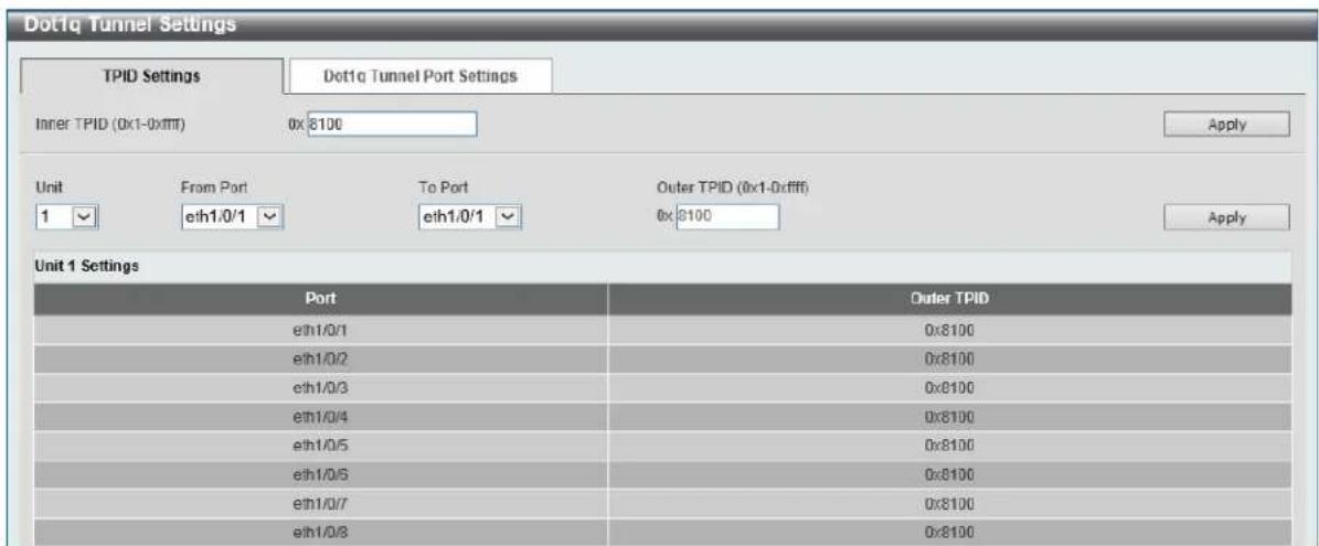
Figure 5-30 Dot1q Tunnel Settings Window
The fields that can be configured in TPID Settings are described below:
| Parameter Description | |
| Inner TPID | Enter the inner TPID value here. This value is in the hexadecimal form. The range is from 0x1 to 0xFFFF. The inner TPID is used to decide if the ingress packet is C-tagged. The Inner TPID is per system configurable. |
| Unit | Select the switch's unit ID that will be used here. |
| From Port ~ To Port | Select the switch's port range that will be used here. |
| Outer TPID | Enter the outer TPID value here. This value is in the hexadecimal form. The range is from 0x1 to 0xFFFF. |
Click the Apply button to accept the changes made.
After clicking the Dot1q Tunnel Port Settings tab, the following page will appear.
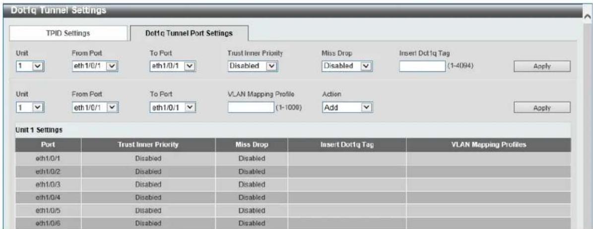
Figure 5-31 Dot1q Tunnel Settings (Dot1q Tunnel Port Settings) Window
The fields that can be configured in Dot1q Tunnel Port Settings are described below:
| Parameter Description | |
| Unit | Select the switch's unit ID that will be used here. |
| From Port ~ To Port | Select the switch's port range that will be used here. |
| Trust Inner Priority | Select to enable or disable the 802.1Q inner trust priority feature here. When the trusting priority option, on an 802.1Q tunnel port, is enabled the priority of the VLAN tag in the received packets will be copied to the service VLAN tag. |
| Miss Drop | Select to enable or disable the miss drop feature here. If the VLAN mapping miss drop option is enabled on the receiving port, when the original VLAN of the received packets cannot match the VLAN mapping entries or rules on this port, the received packets will be dropped. |
| Insert Dot1q Tag | Enter the 802.1Q VLAN ID that is inserted to the untagged packets which are received on the 802.1Q tunnel port(s) here. The range is from 1 to 4094. |
| VLAN Mapping Profile | Enter the ID of the VLAN mapping profile here. A lower ID has a higher priority. The ID range is from 1 to 1000. |
| Action | Select Add to add a new entry based in the information entered. Select Remove to remove an entry based in the information entered. |
Click the Apply button to accept the changes made.
VLAN Mapping
This window is used to view and configure the VLAN mapping settings. If a profile is applied on an interface, the switch matches the incoming packets according to the rules of the profile. If the packets match a rule, the action of the rule will be taken. The action may be adding or replacing the outer-VID. Optionally, specify the priority of the new outer-TAG or specify the packets new inner-VID.
The match order depends on the rule's sequence number of the profile and stopped when first matched. If the sequence number is not specified, it will be allocated automatically. The sequence number begins from 10 and the increment is 10. Multiple different types of profiles could be configured onto one interface.
To view the following window, click L2 Features > VLAN Tunnel > VLAN Mapping, as shown below:
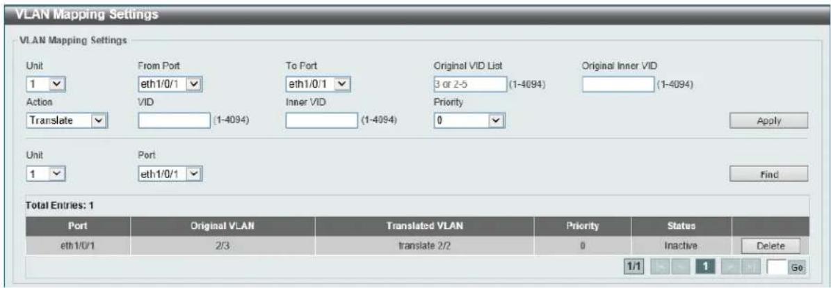
Figure 5-32 VLAN Mapping Settings Window
The fields that can be configured in VLAN Mapping Settings are described below:
| Parameter Description | |
| Unit | Select the switch's unit ID that will be used here. |
| From Port ~ To Port | Select the switch's port range that will be used here. |
| Port | Select the switch's port that will be used for the search here. |
| Original VID List | Enter the original VLAN's ID list here. The range is from 1 to 4094. |
| Original Inner VID | Enter the original inner VLAN's ID here. The range is from 1 to 4094. |
| Action | Select the action that will be taken here. Options to choose from are Translate and Dot1q-tunnel.·Translate: Specifies that the outer-VID will be added for matched packets.·Dot1q-tunnel: Specifies that the outer-VID will replace the outer-VID of the matched packets. |
| VID | Enter the VLAN's ID here. The range is from 1 to 4094. |
| Inner VID | Enter the inner VLAN's ID here. The range is from 1 to 4094. |
| Priority | Select the 802.1p priority value here. The range is from 0 to 7. A lower value has a higher priority. |
Click the Apply button to accept the changes made.
Click the Find button to locate a specific entry based on the information entered.
Click the Delete button to delete the specified entry.
This window is used to view and configure the VLAN mapping profile settings.
To view the following window, click L2 Features > VLAN Tunnel > VLAN Mapping Profile, as shown below:
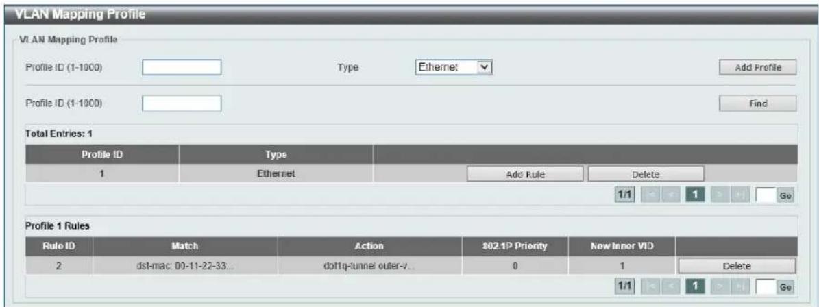
Figure 5-33 VLAN Mapping Profile Window
The fields that can be configured in VLAN Mapping Profile are described below:
| Parameter Description | |
| Profile ID | Enter the ID of the VLAN mapping profile here. A lower ID has a higher priority. The ID range is from 1 to 1000. |
| Type | Select the profile type here. Different profiles can match different fields. Options to choose from are Ethernet, IP, IPv6, and Ethernet-IP.Ethernet:The profile can match Layer 2 fields.IP:The profile can match Layer 3 IP fields.IPv6:The profile can match IPv6 destination or source addresses. |
Click the Add Profile button to add a new VLAN mapping profile.
Click the Find button to locate a specific entry based on the information entered.
After clicking the Add Rule button next to an Ethernet type profile, the following page will appear.
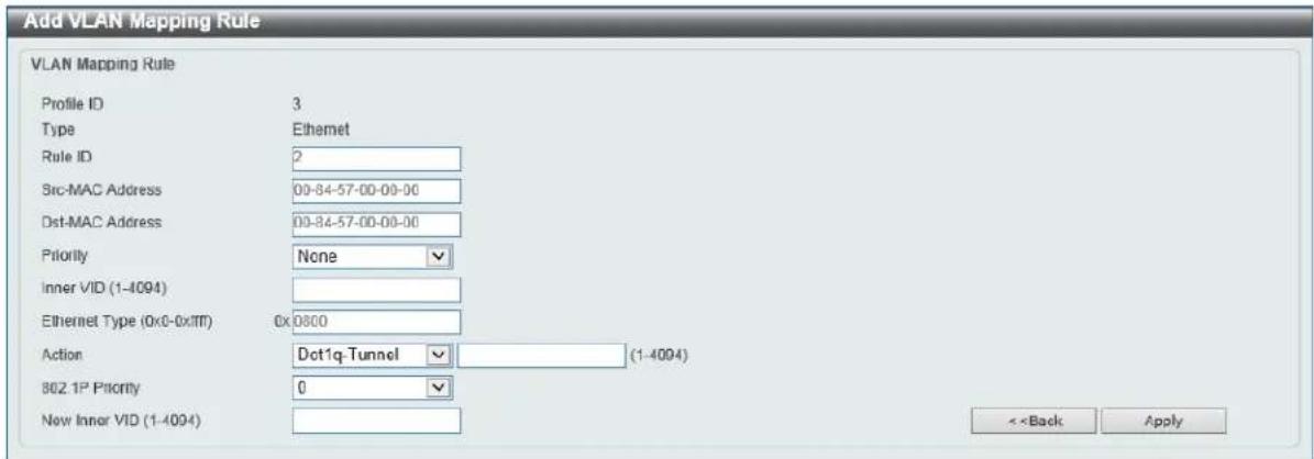
| Parameter Description | |
| STP State | Select to enable or disable the STP global state here. |
| Parameter Description | |
| STP New Root Trap | Select to enable or disable the STP new root trap option here. |
| STP Topology Change Trap | Select to enable or disable the STP topology change trap option here. |
| Parameter Description | |
| STP Mode | Select the STP mode used here. Options to choose from are MSTP, RSTP, and STP. |
| Parameter Description | |
| Priority | Select the STP priority value here. This value is between 0 and 61440. By default, this value is 32768. The lower the value, the higher the priority. |
| Parameter Description | |
| Bridge Max Age | Enter the bridge's maximum age value here. This value must be between 6 and 40 seconds. By default, this value is 20 seconds. The maximum age value may be set to ensure that old information does not endlessly circulate through redundant paths in the network, preventing the effective propagation of the new information. Set by the Root Bridge, this value will aid in determining that the switch has spanning tree configuration values consistent with other devices on the bridged LAN. |
| Bridge Hello Time | After selecting RSTP/STP as the Spanning Tree Mode, this parameter will be available. Enter the bridge's hello time value here. This value must be between 1 and 2 seconds. By default, this value is 2 seconds. This is the interval between two transmissions of BPDU packets sent by the Root Bridge to tell all other switches that it is indeed the Root Bridge. This field will only appear here when STP or RSTP is selected for the STP Version. For MSTP, the Hello Time must be set on a port per port basis. |
| Bridge Forward Time | Enter the bridge's forwarding time value here. This value must be between 4 and 30 seconds. By default, this value is 15 seconds. Any port on the switch spends this time in the listening state while moving from the blocking state to the forwarding state. |
| TX Hold Count | Enter the transmit hold count value here. This value must be between 1 and 10 times. By default, this value is 6 times. This value is used to set the maximum number of Hello packets transmitted per interval. |
| Max Hops | Enter the maximum number of hops that are allowed. This value must be between 1 and 40 hops. By default, this value is 20 hops. This value is used to set the number of hops between devices in a spanningtree region before the BPDU (bridge protocol data unit) packet sent by the switch will be discarded. Each switch on the hop count will reduce the hop count by one until the value reaches zero. The switch will then discard the BDPU packet and the information held for the port will age out. |
| NNI BPDU Address | Select the NNI BPDU Address option here. Options to choose from are Dot1d and Dot1ad. By default, this option is Dot1d. This parameter is used to determine the BPDU protocol address for STP in the service provide site. It can use an 802.1d STP address, 802.1ad service provider STP address, or a user defined multicast address. |
STP Port Settings
This window is used to view and configure the STP port settings. To view the following window, click L2 Features > STP > STP Port Settings, as shown below:  Figure 5-39 STP Port Settings Window The fields that can be configured are described below:| Parameter Description | |
| Unit | Select the switch unit that will be used for this configuration here. |
| From Port ~ To Port | Select the range of ports that will be used for this configuration here. |
| Cost | Enter the cost value here. This value must be between 1 and 200000000. This value defines a metric that indicates the relative cost of forwarding packets to the specified port list. Port cost can be set automatically or as a metric value. The default value is 0 (auto). Setting 0 for the external cost will automatically set the speed for forwarding packets to the specified port(s) in the list for optimal efficiency. The default port cost for a 100Mbps port is 200000, a Gigabit port is 20000, and a 10 Gigabit port is 2000. The lower the number, the greater the probability the port will be chosen to forward packets. |
| State | Select to enable or disable the STP port state. |
| Guard Root | Select to enable or disable the guard root function. |
| Link Type | Select the link type option here. Options to choose from are Auto, P2P, and Shared. A full-duplex port is considered to have a point-to-point (P2P) connection. On the opposite, a half-duplex port is considered to have a Shared connection .The port cannot transit into the forwarding state rapidly by setting the link type to Shared. By default this option is Auto. |
| Port Fast | Select the port fast option here. Options to choose from are Network, Disabled, and Edge.In the Network mode the port will remain in the non-port-fast state for three seconds. The port will change to the port-fast state if no BPDU is received and changes to the forwarding state. If the port received the BPDU later, it will change to the non-port-fast state.In the Disable mode, the port will always be in the non-port-fast state. It will always wait for the forward-time delay to change to the forwarding state.In the Edge mode, the port will directly change to the spanning-tree forwarding state when a link-up occurs without waiting for the forward-time delay. If the interface receives a BPDU later, its operation state changes to the non-port-fast state.By default, this option is Network. |
| TCN Filter | Select to enable or disable the TCN filter option. Enabling TC filtering on a port is useful for an ISP to prevent the external bridge to a core region of the network, causing address flushing in that region, possibly because those bridges are not under the full control of the administrator. When a port is set to the TCN filter mode, the TC event received by the port will be ignored. By default, this option is Disabled. |
| BPDU Forward | Select to enable or disable BPDU forwarding. If enabled, the received STP BPDU will be forwarded to all VLAN member ports in the untagged form. By default, this option is Disabled. |
| Priority | Select the priority value here. Options to choose from are 0 to 240. By default this option is 0. A lower value has higher priority. |
| Hello Time | Enter the hello time value here. This value must be between 1 and 2 seconds. This value specifies the interval that a designated port will wait between the periodic transmissions of each configuration message. |
MST Configuration Identification
This window is used to view and configure the MST configuration identification settings. These settings will uniquely identify a multiple spanning tree instance set on the switch. The switch initially possesses one CIST, or Common Internal Spanning Tree, of which the user may modify the parameters for but cannot change the MSTI ID for, and cannot be deleted. To view the following window, click L2 Features > STP > MST Configuration Identification, as shown below:  Figure 5-40 MST Configuration Identification Window The fields that can be configured for MST Configuration Identification are described below:| Parameter Description | |
| Configuration Name | Enter the MST. This name uniquely identifies the MSTI (Multiple Spanning Tree Instance). If a Configuration Name is not set, this field will show the MAC address to the device running MSTP. |
| Revision Level | Enter the revision level value here. This value must be between 0 and 65535. By default, this value is 0. This value, along with the Configuration Name, identifies the MSTP region configured on the switch. |
| Parameter Description | |
| Instance ID | Enter the instance ID here. This value must be between 1 and 64. |
| Action | Select the action that will be taken here. Options to choose from are Add VID and Remove VID. |
| VID List | Enter the VID list value here. This field is used to specify the VID range from configured VLANs set on the switch. |
STP Instance
This window is used to view and configure the STP instance settings. To view the following window, click L2 Features > STP > STP Instance, as shown below:  Figure 5-41 STP Instance Window Click the Edit button to re-configure the specific entry.MSTP Port Information
This window is used to view and configure the MSTP port information settings. To view the following window, click L2 Features > STP > MSTP Port Information, as shown below:  Figure 5-42 MSTP Port Information Window The fields that can be configured are described below:| Parameter Description | |
| Unit | Select the switch unit that will be used for this display here. |
| Port | Select the port number that will be cleared here. |
ERPS (G.8032)
ERPS
This window is used to view and configure Ethernet Ring Protection Switching (ERPS) settings. To view the following window, click L2 Features > ERPS (G.8032) > ERPS, as shown below:  Figure 5-43 ERPS Window The fields that can be configured in ERPS Global Settings are described below:| Parameter Description | |
| ERPS Trap Status | Select to enable or disable the ERPS trap status here. |
| Parameter Description | |
| Ring Name | Enter the Ethernet Ring Protection (ERP) instance's name here. This name can be up to 32 characters long. |
| Parameter Description | |
| Instance ID | Select the checkbox and enter the ERP instance number here. This value must be between 1 and 32. Select the Specify radio button to configure this parameter as per normal. Select the None radio button to revert this parameter to the default setting. |
| Sub Ring Name | Select the checkbox and enter the physical ring's sub-ring name here. This name can be up to 32 characters long. Select theSpecifyradio button to configure this parameter as per normal. Select theNoneradio button to revert this parameter to the default setting. |
| Port0 | Select the checkbox and then select the switch's unit ID and the port number that will be the first ring port of the physical ring. Select theSpecifyradio button to configure this parameter as per normal. Select theNoneradio button to revert this parameter to the default setting. |
| Port1 | Select the checkbox and then select the switch's unit ID and the port number that will be the second ring port of the physical ring. Select theNoneoption, from the drop-down menu, specifies that the interconnected node is a local node endpoint of an open ring. Select theSpecifyradio button to configure this parameter as per normal. Select theNoneradio button to revert this parameter to the default setting. |
| Parameter Description | |
| Description | Select the checkbox and enter the ERP instance's description here. This description can be up to 64 characters long. Select the Specify radio button to configure this parameter as per normal. Select the None radio button to revert this parameter to the default setting. |
| R-APS Channel VLAN | Select the checkbox and enter the R-APS channel VLAN's ID for the ERP instance here. The APS channel VLAN of a sub-ring instance is also the virtual channel of the sub-ring. This value must be between 1 and 4094. Select the Specify radio button to configure this parameter as per normal. Select the None radio button to revert this parameter to the default setting. |
| Inclusion VLAN List | Select the checkbox and enter the inclusion VLAN list here. A range is identified when a hyphen (-) is used. For example VLANs 1 to 5 can be entered as 1-5. A list is identified when commas (,) are used. For example, use VLANs 1,3,5. The VLANs specified here will be protected by the ERP mechanism. Select the Specify radio button to configure this parameter as per normal. Select the None radio button to revert this parameter to the default setting. |
| MEL | Select the checkbox and enter the ring MEL value of the ERP instance here. This value must be between 0 and 7. The configured MEL value of all ring nodes that participate in the same ERP instance should be identical. Select the Specify radio button to configure this parameter as per normal. Select the None radio button to revert this parameter to the default setting. |
| Profile Name | Select the checkbox and enter the G.8032 profile's name here that will be associated with this ERP instance. Multiple ERP instances can be associated with the same G.8032 profile. The instances associated with the same profile protect the same set of VLANs, or the VLANs protected by one instance are a subset of LANs protected by another instance. This name can be up to 32 characters long. Select the Specify radio button to configure this parameter as per normal. Select the None radio button to revert this parameter to the default setting. |
| RPL Port | Select the checkbox and then select the RPL port option here. Options to choose from are Port0 and Port1. The option selected will beconfigured as the RPL port. |
| RPL Owner | Select the checkbox and then select whether this node is the RPL owner or neighbor. Options to choose from are Enabled and Disabled. Enabling this option will specify this RPL as an owner. |
| Activate | Select the checkbox and then select whether or not to active this ERP instance. Options to choose from are Enabled and Disabled. Enabling this option will active this ERP instance. |
ERPS Profile
This window is used to view and configure the Ethernet Ring G.8032 profile settings. To view the following window, click L2 Features > ERPS (G.8032) > ERPS Profile, as shown below:  Figure 5-47 ERPS Profile Window The fields that can be configured in Ethernet Ring G.8032 Profile are described below:| Parameter Description | |
| Profile Name | Enter the G.8032 profile's name here. This name can be up to 32 characters long. Multiple ERP instances can be associated with the same G.8032 profile. The instances associated with the same profile protect the same set of VLANs, or the VLANs protected by one instance are a subset of LANs protected by another instance. |
| Parameter Description | |
| TCN Propagation | Select the checkbox and then select the TCN propagation state. Options to choose from are Enable and Disabled. This function is used to enable the propagation of the topology change notifications from the sub-ERP instance to the major instance. |
| Revertive | Select the checkbox and then select the revertive state. Options to choose from are Enable and Disabled. This function is used to revert back to the working transport entity, for example, when the RPL was blocked. |
| Guard Timer | Select the checkbox and enter the guard timer value here. This value must be between 10 and 2000 milliseconds. By default, this value is 500 milliseconds. |
| Hold-Off Timer | Select the checkbox and enter hold-off timer value here. This value must be between 0 and 10 seconds. By default, this value is 0 seconds. |
| WTR Timer | Select the checkbox and enter the WTR timer value here. This value must be between 1 and 12 minutes. By default, this value is 5 minutes. |
Loopback Detection
The Loopback Detection (LBD) function is used to detect the loop created by a specific port. This feature is used to temporarily shut down a port on the Switch when a CTP (Configuration Testing Protocol) packet has been looped back to the Switch. When the Switch detects CTP packets received from a port or a VLAN, this signifies a loop on the network. The Switch will automatically block the port or the VLAN and send an alert to the administrator. The Loopback Detection port will restart (change to normal state) when the Loopback Detection Recover Time times out. The Loopback Detection function can be implemented on a range of ports at a time. The user may enable or disable this function using the dropdown menu. To view the following window, click L2 Features > Loopback Detection, as shown below:  Figure 5-49 Loopback Detection Window The fields that can be configured in Loopback Detection Global Settings are described below:| Parameter Description | |
| Loopback Detection State | Select to enable or disable loopback detection. The default is Disabled. |
| Mode | Select the loopback detection mode. Options to choose from are Port-based and VLAN-based. |
| Enabled VLAN ID List | Enter the VLAN ID for loop detection. This only takes effect when the VLAN-based is selected in the Mode drop-down list. |
| Interval | Enter the interval in seconds that the device will transmit all the CTP (Configuration Test Protocol) packets to detect a loop-back event. The valid range is from 1 to 32767 seconds. The default setting is 10 seconds. |
| Trap State | Select to enable or disable the loopback detection trap state. |
| Parameter Description | |
| Unit | Select the switch unit that will be used for this configuration here. |
| From Port ~ To Port | Select the appropriate port range used for the configuration here. |
| State | Select this option to enable or disable the state of the port. |
Link Aggregation
Understanding Port Trunk Groups
Port trunk groups are used to combine a number of ports together to make a single high-bandwidth data pipeline. The switch supports up to 32 port trunk groups with up to 12 ports in each group. flowchart
graph TD
    A["An Example of Link Aggregation"] --> B["Ethernet Backbone Uplink"]
    B --> C["Port Trunk Group"]
    C --> D["D-Link Server"]
    D --> E["1000 Mbps Connection"]
    D --> F["1000 Mbps Connection"]
    D --> G["1000 Mbps Connection"]
    E --> H["End Station Clients"]
    F --> H
    G --> H
| Parameter Description | |
| System Priority | Enter the system's priority value used here. This value must be between 1 and 65535. By default, this value is 32768. The system priority determines which ports can join a port-channel and which ports are put in the stand-alone mode. The lower value has a higher priority. If two or more ports have the same priority, the port number determines the priority |
| Load Balance Algorithm | Select the load balancing algorithm that will be used here. Options to choose from are Source MAC, Destination MAC, Source Destination MAC, Source IP, Destination IP, Source Destination IP, Source L4 Port, Destination L4 Port, and Source Destination L4 Port. By default, this option is Source Destination MAC. |
| Parameter Description | |
| Unit | Select the switch unit that will be used for this configuration here. |
| From Port ~ To Port | Select the list of ports that will be associated with this configuration here. |
| Group ID | Enter the channel group number here. This value must be between 1 and 32. The system will automatically create the port-channel when a physical port first joins a channel group. An interface can only join one channel-group. |
| Mode | Select the mode option here. Options to choose from are On, Active, and Passive. If the mode On is specified, the channel group type is static. If the mode Active or Passive is specified, the channel group type is LACP. A channel group can only consist of either static members or LACP members. Once the type of channel group has been determined, other types of interfaces cannot join the channel group. |
L2 Protocol Tunnel
This window is used to view and configure the Layer 2 protocol tunnel settings. To view the following window, click L2 Features > L2 Protocol Tunnel, as shown below:  Figure 5-53 L2 Protocol Tunnel (L2 Protocol Tunnel Global Setting) Window The fields that can be configured for L2 Protocol Tunnel Global Settings are described below:| Parameter Description | |
| CoS for Encapsulated Packets | Select the CoS value for encapsulated packets here. This value is between 0 and 7. Tick the Default option to use the default value. |
| Drop Threshold | Enter the drop threshold value here. This value must be between 100 and 20000. By default, this value is 0. The tunneling of the Layer 2 protocol packets will consume CPU processing power in encapsulating, decapsulating, and forwarding of the packet. Use this option to restrict the CPU processing bandwidth consumed by specifying a threshold on the number of all Layer 2 protocol packets that can be processed by the system. When the maximum number of packets is exceeded, the excessive protocol packets are dropped. |
| Parameter Description | |
| Unit | Select the switch unit that will be used for this configuration here. |
| From Port ~ To Port | Select the range of ports that will be used for this configuration here. |
| Action | Select Add to add a new entry based in the information entered.Select Delete to delete an entry based in the information entered. |
| Type | Select the type option here. Options to choose from are None, Shutdown, and Drop. |
| Tunneled Protocol | Select the tunneled protocol option here. Options to choose from are GVRP, STP, Protocol MAC, and All. |
| Protocol MAC | After selecting theProtocol MACoption as theTunneled Protocol, the following option will be available. Select the protocol MAC option here. Options to choose from are01-00-0C-CC-CC-CCand01-00-0C-CC-CC-CD. |
| Threshold | After selecting theShutdown or Dropoptions as theType, the following parameter will be available. Enter the threshold value here. This value must be between 1 and4096. |
L2 Multicast Control
IGMP Snooping
Internet Group Management Protocol (IGMP) snooping allows the Switch to recognize IGMP queries and reports sent between network stations or devices and an IGMP host.IGMP Snooping Settings
In order to use IGMP Snooping it must first be enabled for the entire Switch under IGMP Global Settings at the top of the window. You may then fine-tune the settings for each VLAN by clicking the corresponding Edit button. When enabled for IGMP snooping, the Switch can open or close a port to a specific multicast group member based on IGMP messages sent from the device to the IGMP host or vice versa. The Switch monitors IGMP messages and discontinues forwarding multicast packets when there are no longer hosts requesting that they continue. To view the following window, click L2 Features > L2 Multicast Control > IGMP Snooping > IGMP Snooping Settings, as shown below:  Figure 5-55 IGMP Snooping Settings Window The fields that can be configured in Global Settings are described below:| Parameter Description | |
| Global State | Select this option to enable or disable IGMP snooping global state. |
| Parameter Description | |
| VID | Enter a VLAN ID from 1 to 4094, and select to enable or disable IGMP snooping on the VLAN. |
| Parameter Description | |
| VID | Enter a VLAN ID from 1 to 4094. |
| Parameter Description | |
| Minimum Version | Select the minimum version of IGMP hosts that is allowed on the VLAN. Options to choose from are 1, 2, and 3. |
| Fast Leave | Select this option to enable or disable the IGMP snooping fast leave function. If enabled, the membership is immediately removed when the system receive the IGMP leave message. |
| Report Suppression | Select this option to enable or disable the report suppression. The report suppression function only works for IGMPv1 and IGMPv2 traffic. When report suppression is enabled, the Switch suppresses the duplicate reports sent by hosts. The suppression for the same group report or leave will continue until the suppression time expired. For report or leave messages to the same group, only one report or leave message is forwarded. The remaining report and leave messages are suppressed. |
| Suppression Time | Enter the interval of suppressing duplicate IGMP reports or leaves. The range is from 1 to 300. |
| Querier State | Select this option to enable or disable the querier state. |
| Query Version | Select the general query packet version sent by the IGMP snooping querier. Options to choose from are 1, 2, and 3. |
| Query Interval | Enter the interval at which the IGMP snooping querier sends IGMP general query messages periodically. The range is from 1 to 31744. |
| Max Response Time | Enter the maximum response time, in seconds, advertised in IGMP snooping queries. The range is from 1 to 25. |
| Robustness Value | Enter the robustness variable used in IGMP snooping. The range is from 1 to 7. |
| Las Member Query Interval | Enter the interval at which the IGMP snooping querier sends IGMP group-specific or group-source-specific (channel) query messages. The range is from 1 to 25. |
| Proxy Reporting | Select this option to enable or disable the proxy-reporting function. |
| Source Address | Enter the source IP of proxy reporting. This is available when Enabled is selected in Proxy Reporting. |
| Rate Limit | Enter the rate limit value here. The range is from 1 to 1000. Tick the No Limit option to apply no rate limit on this profile. |
| Ignore Topology Change | Select to enable or disable the ignore topology change feature here. |
IGMP Snooping Groups Settings
This window is used to view and configure and view the IGMP snooping static group, and view IGMP snooping group. To view the following window, click L2 Features > L2 Multicast Control > IGMP Snooping > IGMP Snooping Groups Settings, as shown below:  Figure 5-58 IGMP Snooping Groups Settings Window The fields that can be configured in IGMP Snooping Static Groups Settings are described below:| Parameter Description | |
| VID | Enter a VLAN ID of the multicast group. The range is from 1 to 4094. |
| Group Address | Enter an IP multicast group address. |
| Unit | Select the switch unit that will be used for this configuration here. |
| From Port ~ To Port | Select the appropriate port range used for the configuration here. |
| VID | Click the radio button and enter a VLAN ID of the multicast group. The range is from 1 to 4094. |
| Group Address | Click the radio button and enter an IP multicast group address. |
| Parameter Description | |
| VID | Click the radio button and enter a VLAN ID of the multicast group. The range is from 1 to 4094. |
| Group Address | Click the radio button and enter an IP multicast group address. |
IGMP Snooping Filter Settings
This window is used to view and configure the IGMP snooping feature's filter settings. To view the following window, click L2 Features > L2 Multicast Control > IGMP Snooping > IGMP Snooping Filter Settings, as shown below:  Figure 5-59 IGMP Snooping Filter Settings Window The fields that can be configured in IGMP Snooping Rate Limit Settings are described below:| Parameter Description | |
| Unit | Select the switch's unit ID that will be used here. |
| From Port ~ To Port | Select the switch's port range that will be used here. This is onlyavailable if the Port option was selected as the action below. |
| Limit Number | Enter the limit number here. This is to configure the rate of IGMP control packets that the switch can process on a specific interface. The range is from 1 to 1000 packets per second. Select the No Limit option to remove the limitation. |
| Action | Select the action that will be taken here. Options to choose from are Port and VLAN. |
| VID | Enter the VLAN's ID here. This is the Layer 2 VLAN on a trunk port and applies the filter to packets that arrive on that VLAN. The range is from 1 to 4094. This is only available if the VLAN option was selected as the action. |
| Parameter Description | |
| Unit | Select the switch unit that will be used for this configuration here. |
| From Port ~ To Port | Select the appropriate port range used for the configuration here. |
| Limit Number | Enter the limit number here. This is used to set the limitation on the number of IGMP cache entries that can be created. The range is from 1 to 2048. |
| Exceed Action | Select the exceed action here. This parameter specifies the action for handling newly learned groups when the limitation is exceeded. Options to choose from are Default, Drop and Replace.Default: Specifies that the default action will be taken.Drop: Specifies that the new group will be dropped.Replace: Specifies that the new group will replace the oldest group. |
| Except ACL Name | Enter the standard IP access list's name here. The group (*,G), or channel (S,G) permitted by the access list will be excluded from the limit. To permit a channel (S,G), specify S in the source address field and G in the destination address field of the access list entry. To permit a group (*,G), specify “any” in the source address field and G in the destination address field of the access list entry. This name can be up to 32 characters long. |
| VID | Enter the Layer 2 VLAN's name on a trunk port here. This applies the filter to packets that arrive on that VLAN. The range is from 1 to 4094. |
| Parameter Description | |
| Unit | Select the switch unit that will be used for this configuration here. |
| From Port ~ To Port | Select the appropriate port range used for the configuration here. |
| Action | Select Add to add a new entry based in the information entered.Select Delete to delete an entry based in the information entered. |
| ACL Name | Enter the standard IP access list's name here. This is used to permit users to join a group (*, G), specify “any” in source address field and G in destination address field of the access list entry. This name can be up to 32 characters long. |
| VID | Enter the VLAN's ID used for this configuration here. The range is from 1 to 4094. |
| Parameter Description | |
| Unit | Select the switch's unit ID that will be used here. |
| From Port ~ To Port | Select the switch's port range that will be used here. |
IGMP Snooping Mrouter Settings
This window is used to view and configure the specified interface(s) as the multicast router ports or as forbidden to be multicast router ports on the Switch. To view the following window, click L2 Features > L2 Multicast Control > IGMP Snooping > IGMP Snooping Mrouter Settings, as shown below:  Figure 5-60 IGMP Snooping Mrouter Settings Window The fields that can be configured in IGMP Snooping Mrouter Settings are described below:| Parameter Description | |
| VID | Enter the VLAN ID used here. The range is from 1 to 4094. |
| Configuration | Select the port configuration. Options to choose from are Port, and Forbidden Port.Port- Select to have the configured ports to be static multicast router ports.Forbidden Port- Select to have the configured ports not to be multicast router ports. |
| Unit | Select the switch unit that will be used for this configuration here. |
| From Port ~ To Port | Select the appropriate port range used for the configuration here. |
| Parameter Description | |
| VID | Enter the VLAN ID used here. The range is from 1 to 4094. |
IGMP Snooping Statistics Settings
This window is used to view and clear the IGMP snooping related statistics. To view the following window, click L2 Features > L2 Multicast Control > IGMP Snooping > IGMP Snooping Statistics Settings, as shown below:  Figure 5-61 IGMP Snooping Statistics Settings Window The fields that can be configured in IGMP Snooping Statistics Settings are described below:| Parameter Description | |
| Statistics | Select the interface here. Options to choose from are All, VLAN, and Port. |
| VID | Enter a VLAN ID between 1 and 4094. This is available when VLAN is selected in the Statistics drop-down list. |
| Unit | Select the switch unit that will be used for this configuration here. This is available when Port is selected in the Statistics drop-down list. |
| From Port ~ To Port | Select the appropriate port range used for the configuration here. This is available when Port is selected in the Statistics drop-down list. |
| Parameter Description | |
| Find Type | Select the interface type. Options to choose from are VLAN, and Port. |
| VID | Enter a VLAN ID between 1 and 4094. This is available when VLAN is selected in the Find Type drop-down list. |
| Unit | Select the switch unit that will be used for this configuration here. This is available when Port is selected in the Find Type drop-down list. |
| From Port ~ To Port | Select the appropriate port range used for the configuration here. This is available when Port is selected in the Find Type drop-down list. |
MLD Snooping
Multicast Listener Discovery (MLD) Snooping is an IPv6 function used similarly to IGMP snooping in IPv4. It is used to discover ports on a VLAN that are requesting multicast data. Instead of flooding all ports on a selected VLAN with multicast traffic, MLD snooping will only forward multicast data to ports that wish to receive this data through the use of queries and reports produced by the requesting ports and the source of the multicast traffic. MLD snooping is accomplished through the examination of the layer 3 part of an MLD control packet transferred between end nodes and a MLD router. When the Switch discovers that this route is requesting multicast traffic, it adds the port directly attached to it into the correct IPv6 multicast table, and begins the process of forwarding multicast traffic to that port. This entry in the multicast routing table records the port, the VLAN ID, and the associated multicast IPv6 multicast group address, and then considers this port to be an active listening port. The active listening ports are the only ones to receive multicast group data.MLD Control Messages
These types of messages are transferred between devices using MLD snooping. These messages are all defined by four ICMPv6 packet headers, labeled 130, 131, 132, and 143. - Multicast Listener Query - Similar to the IGMPv2 Host Membership Query for IPv4, and labeled as 130 in the ICMPv6 packet header, this message is sent by the router to ask if any link is requesting multicast data. There are two types of MLD query messages emitted by the router. The General Query is used to advertise all multicast addresses that are ready to send multicast data to all listening ports, and the Multicast Specific query, which advertises a specific multicast address that is also ready. These two types of messages are distinguished by a multicast destination address located in the IPv6 header and a multicast address in the Multicast Listener Query Message. - Multicast Listener Report, Version 1 - Comparable to the Host Membership Report in IGMPv2, and labeled as 131 in the ICMP packet header, this message is sent by the listening port to the Switch stating that it is interested in receiving multicast data from a multicast address in response to the Multicast Listener Query message. - Multicast Listener Done - Akin to the Leave Group Message in IGMPv2, and labeled as 132 in the ICMPv6 packet header, this message is sent by the multicast listening port stating that it is no longer interested in receiving multicast data from a specific multicast group address, therefore stating that it is “done” with the multicast data from this address. Once this message is received by the Switch, it will no longer forward multicast traffic from a specific multicast group address to this listening port. - Multicast Listener Report, Version 2 - Comparable to the Host Membership Report in IGMPv3, and labeled as 143 in the ICMP packet header, this message is sent by the listening port to the Switch stating that it is interested in receiving multicast data from a multicast address in response to the Multicast Listener Query message.MLD Snooping Settings
This window is used to view and configure the MLD snooping settings. To view the following window, click L2 Features > L2 Multicast Control > MLD Snooping > MLD Snooping Settings, as shown below:  Figure 5-62 MLD Snooping Settings Window The fields that can be configured in Global Settings are described below:| Parameter Description | |
| Global State | Select this option to enable or disable MLD snooping global state. |
| Parameter Description | |
| VID | Enter a VLAN ID from 1 to 4094, and select to enable or disable MLD snooping on the VLAN. |
| Parameter Description | |
| VID | Enter a VLAN ID from 1 to 4094. |
MLD Snooping VLAN Parameters
MLD Snooping VLAN Parameters VID 2 Status Enabled Minimum Version v1 Fast Leave Disabled (host-based) Report Suppression Disabled Suppression Time 10 seconds Proxy Reporting Disabled Source Address (--) Mrouter Port Learning Enabled Querier State Disabled Query Version v2 Query Interval 125 seconds Max Response Time 10 seconds Robustness Value 2 Last Listener Query Interval 1 seconds Rate Limit 0 Ignore Topology Change Disabled Modify Figure 5-63 MLD Snooping Settings (Show Detail) Window The window displays the detail information about MLD snooping VLAN. Click the Modify button to edit the information in the following window. After clicking the Modify or Edit button in MLD Snooping Settings window, the following window will appear.MLD Snooping VLAN Settings
MLD Snooping VLAN Settings VID (1-4094)  Status \- Enabled - Disabled Minimum Version  Fast Leave ○Enabled ●Disabled Report Suppression ○Enabled ●Disabled Suppression Time (1-300)  Proxy Reporting ○Enabled ●Disabled Mrouter Port Learning ●Enabled ○Disabled Querier State Enabled ●Disabled Query Version  Query Interval (1-31744) 125 sec Max Response Time (1-25) 10 sec Robustness Value (1-7) 2 Last Listener Query Interval (1-25) 1 sec Rate Limit (1-1000)  Ignore Topology Change ○Enabled ●Disabled Apply Figure 5-64 MLD Snooping Settings (Modify, Edit) Window The fields that can be configured in MLD Snooping VLAN Settings are described below:| Parameter Description | |
| Minimum Version | Select the minimum version of MLD hosts that is allowed on the VLAN. Options to choose from are 1 and 2. |
| Fast Leave | Select this option to enable or disable the MLD snooping fast leave function. If enabled, the membership is immediately removed when the system receive the MLD leave message. |
| Report Suppression | Select this option to enable or disable the report suppression. |
| Suppression Time | Enter the interval of suppressing duplicate MLD reports or leaves. The range is from 1 to 300. |
| Proxy Reporting | Select this option to enable or disable the proxy-reporting function. |
| Source Address | Enter the source IP of proxy reporting. This is available when Enabled is selected in Proxy Reporting. |
| Mrouter Port Learning | Select this option to enable or disable Mrouter port learning. |
| Querier State | Select this option to enable or disable the querier state. |
| Query Version | Select the general query packet version sent by the MLD snooping querier. Options to choose from are 1, and 2. |
| Query Interval | Enter the interval at which the MLD snooping querier sends MLD general query messages periodically. The range is from 1 to 31744. |
| Max Response Time | Enter the maximum response time, in seconds, advertised in MLD snooping queries. The range is from 1 to 25. |
| Robustness Value | Enter the robustness variable used in MLD snooping. The range is from 1 to 7. |
| Last Listener Query Interval | Enter the interval at which the MLD snooping querier sends MLD group-specific or group-source-specific (channel) query messages. The range is from 1 to 25. |
| Rate Limit | Enter the rate limit value here. The range is from 1 to 1000. Tick the No Limit option to apply no rate limit on this profile. |
| Ignore Topology Change | Select to enable or disable the ignore topology change feature here. |
MLD Snooping Groups Settings
This window is used to view and configure the MLD snooping static group, and view MLD snooping group. To view the following window, click L2 Features > L2 Multicast Control > MLD Snooping > MLD Snooping Groups Settings, as shown below:  Figure 5-65 MLD Snooping Groups Settings Window The fields that can be configured in MLD Snooping Static Groups Settings are described below:| Parameter | Description |
| VID | Enter the VLAN ID of the multicast group here. The range is from 1 to 4094. |
| Group Address | Enter the IPv6 multicast group address here. |
| Unit | Select the switch unit that will be used for this configuration here. |
| From Port ~ To Port | Select the appropriate port range used for the configuration here. |
| VID | Click the radio button and enter a VLAN ID of the multicast group. The range is from 1 to 4094. |
| Group Address | Click the radio button and enter an IP multicast group address. |
| Parameter Description | |
| VID | Click the radio button and enter a VLAN ID of the multicast group. The range is from 1 to 4094. |
| Group Address | Click the radio button and enter an IP multicast group address. |
MLD Snooping Filter Settings
This window is used to view and configure the MLD snooping feature's settings. To view the following window, click L2 Features > L2 Multicast Control > MLD Snooping > MLD Snooping Filter Settings, as shown below:  Figure 5-66 MLD Snooping Filter Settings Window The fields that can be configured in MLD Snooping Rate Limit Settings are described below:| Parameter Description | |
| Unit | Select the switch's unit ID that will be used here. |
| From Port ~ To Port | Select the switch's port range that will be used here. This is only available if the Port option was selected as the action below. |
| Limit Number | Enter the limit number here. This is to configure the rate of MLD control packets that the switch can process on a specific interface. The range is from 1 to 1000 packets per second. Select the No Limit option to remove the limitation. |
| Action | Select the action that will be taken here. Options to choose from are Port and VLAN. |
| VID | Enter the VLAN's ID here. This is the Layer 2 VLAN on a trunk port and applies the filter to packets that arrive on that VLAN. The range is from 1 to 4094. This is only available if the VLAN option was selected as the action. |
| Parameter Description | |
| Unit | Select the switch unit that will be used for this configuration here. |
| From Port ~ To Port | Select the appropriate port range used for the configuration here. |
| Limit Number | Enter the limit number here. This is used to set the limitation on the number of MLD cache entries that can be created. The range is from 1 to 2048. |
| Exceed Action | Select the exceed action here. This parameter specifies the action for handling newly learned groups when the limitation is exceeded.Options to choose from areDefault, DropandReplace.Default: Specifies that the default action will be taken.Drop: Specifies that the new group will be dropped.Replace: Specifies that the new group will replace the oldest group. |
| Except ACL Name | Enter the standard IP access list's name here. The group (*,G), or channel (S,G) permitted by the access list will be excluded from the limit. To permit a channel (S,G), specify S in the source address field and G in the destination address field of the access list entry. To permit a group (*,G), specify “any” in the source address field and G in the destination address field of the access list entry. This name can be up to 32 characters long. |
| VID | Enter the Layer 2 VLAN's name on a trunk port here. This applies the filter to packets that arrive on that VLAN. The range is from 1 to 4094. |
| Parameter Description | |
| Unit | Select the switch unit that will be used for this configuration here. |
| From Port ~ To Port | Select the appropriate port range used for the configuration here. |
| Action | Select Add to add a new entry based in the information entered.Select Delete to delete an entry based in the information entered. |
| ACL Name | Enter the standard IP access list's name here. This is used to permit users to join a group (*, G), specify “any” in source address field and G in destination address field of the access list entry. This name can be up to 32 characters long. |
| VID | Enter the VLAN's ID used for this configuration here. The range is from 1 to 4094. |
| Parameter Description | |
| Unit | Select the switch's unit ID that will be used here. |
| From Port ~ To Port | Select the switch's port range that will be used here. |
MLD Snooping Mrouter Settings
This window is used to view and configure the specified interface(s) as the router ports or forbidden to be IPv6 multicast router ports on the VLAN interface on the Switch. To view the following window, click L2 Features > L2 Multicast Control > MLD Snooping > MLD Snooping Mrouter Settings, as shown below:  Figure 5-67 MLD Snooping Mrouter Settings Window The fields that can be configured in MLD Snooping Mrouter Settings are described below:| Parameter Description | |
| VID | Enter a VLAN ID between 1 and 4094. |
| Configuration | Select the port configuration. Options to choose from are Port, Forbidden Port, and Learn PIMv6.Port- Select to have the configured ports as being connected to multicast-enabled routers.Forbidden Port- Select to have the configured ports as being not connected to multicast-enabled routers.Learn PIMv6- Select to enable dynamic learning of multicast router port. |
| Unit | Select the switch unit that will be used for this configuration here. |
| From Port ~ To Port | Select the appropriate port range used for the configuration here. |
| Parameter Description | |
| VID | Enter a VLAN ID between 1 and 4094. |
MLD Snooping Statistics Settings
This window is used to view and clear the MLD snooping related statistics. To view the following window, click L2 Features > L2 Multicast Control > MLD Snooping > MLD Snooping Statistics Settings, as shown below:  Figure 5-68 MLD Snooping Statistics Settings Window The fields that can be configured in MLD Snooping Statistics Settings are described below:| Parameter Description | |
| Statistics | Select the interface here. Options to choose from are All, VLAN, and Port. |
| VID | Enter a VLAN ID between 1 and 4094. This is available when VLAN is selected in the Statistics drop-down list. |
| Unit | Select the switch unit that will be used for this configuration here. This is available when Port is selected in the Statistics drop-down list. |
| From Port ~ To Port | Select the appropriate port range used for the configuration here. This is available when Port is selected in the Statistics drop-down list. |
| Parameter Description | |
| Find Type | Select the interface type. Options to choose from are VLAN, and Port. |
| VID | Enter a VLAN ID between 1 and 4094. This is available when VLAN is selected in the Find Type drop-down list. |
| Unit | Select the switch unit that will be used for this configuration here. This is available when Port is selected in the Find Type drop-down list. |
| From Port ~ To Port | Select the appropriate port range used for the configuration here. This is available when Port is selected in the Find Type drop-down list. |
Multicast VLAN
Multicast VLAN Settings
This window is used to view and configure the multicast VLAN settings. To view the following window, click L2 Features > L2 Multicast Control > Multicast VLAN > Multicast VLAN Settings, as shown below:  Figure 5-69 Multicast VLAN Settings Window The fields that can be configured in Multicast VLAN Global Settings are described below:| Parameter Description | |
| Multicast VLAN IPv4 State | Select to enable or disable the IPv4 IGMP control packet process in multicast VLANs. |
| Forward Unmatched | Select the enable or disable the forward unmatched feature here. This specifies that if the received IGMP or MLD control packet is untagged, does not match any profile, and the associated default VLAN is a multicast VLAN, or is tagged with a multicast VLAN, but does not match the associated profile, then the packet will be forwarded or dropped based on this setting. By default, the packet will be dropped. |
| Multicast VLAN IPv6 State | Select to enable or disable the IPv6 IGMP control packet process in multicast VLANs. |
| Ignore VLAN | Select the enable or disable the ignore VLAN feature here. This specifies the setting for tagged IGMP or MLD control packets. If enabled, then the packet's VLAN is ignored and taken to match the profile to find its multicast VLAN. When this option is enabled, the switch will ignore the VLAN of the receiving IGMP or MLD control packet and try to find a match profile. |
| VID | Enter the VLAN ID of the multicast VLAN that will be created or deleted here. The range is 2 to 4094. |
| VLAN Name | Enter the VLAN name of the multicast VLAN that will be created or deleted here. |
| Parameter Description | |
| VID | Enter the multicast VLAN's ID that will be used here. The range is 2 to 4094. |
| Action | SelectAddto add a new entry based in the information entered.SelectDeleteto delete an entry based in the information entered. |
| Role | Select the role here. Options to choose from areReceiverand Source.Receiver:Specifies to configure the port as a subscriber port that can only receive multicast data in the multicast VLAN.Source:Specifies to configure the port as an uplink port that can send multicast data in the multicast VLAN. |
| Type | Select the type here. Options to choose from areTaggedand Untagged.Tagged:Specifies that if a port is a tagged member, the packets sent from the port are tagged with the Multicast VLAN ID.Untagged:Specifies that if the port is an untagged member, then the packets will be forwarded in the untagged form. |
| Unit | Select the switch's unit ID that will be used here. |
| From Port ~ To Port | Select the switch's port range that will be used here. |
| Parameter Description | |
| VID | Enter the multicast VLAN’s ID that will be used here. The range is 2 to 4094. |
| Action | SelectAddto add a new entry based in the information entered.SelectDeleteto delete an entry based in the information entered. |
| IP Type | Select the IP type here. Options to choose from areIPv4andIPv6.IPv4: Specifies to the remap priority for IPv4 multicast packets forwarded on the multicast VLAN.IPv6: Specifies to the remap priority for IPv6 multicast packets forwarded on the multicast VLAN. |
| Priority | Select the priority value here. The range is from 0 to 7. A lower value represents a higher priority. |
| Parameter Description | |
| VID | Enter the multicast VLAN's ID that will be used here. The range is 2 to 4094. |
| Action | SelectAddto add a new entry based in the information entered.SelectDeleteto delete an entry based in the information entered. |
| Address Type | Select the address type here. Options to choose from areIPv4and IPv6.IPv4: Specifies to enter the source IPv4 address for IGMP control packet reporting up to routers.IPv6: Specifies to enter the source IPv6 address for MLD control packet reporting up to routers. |
| IP Address | Enter the IPv4/IPv6 address here. |
| From | Select the “from” option here. Options to choose from areReceiver, Source, and Both.Receiver: Specifies that the source IPv4/IPv6 address of the IGMP/MLD report/leave packet received on any multicast VLAN receiver port will be replaced.Source: Specifies that the source IPv4/IPv6 address of the IGMP/MLD report/leave packet received on any multicast VLAN source port will be replaced.Both: Specifies that the source IPv4/IPv6 address of the IGMP/MLD report/leave packet received on any port in the multicast VLAN will be replaced. |
| Parameter Description | |
| VID | Enter the multicast VLAN's ID that will be used here. The range is 2 to 4094. |
Multicast VLAN Group Settings
This widow is used to view and configure the multicast VLAN's group settings. To view the following window, click L2 Features > L2 Multicast Control > Multicast VLAN > Multicast VLAN Group Settings, as shown below:  Figure 5-70 Multicast VLAN Group Settings Window The fields that can be configured in Group Profile Settings are described below:| Parameter Description | |
| Profile Name | Enter the group profile name for the multicast VLAN feature here. This name can be up to 32 characters long. |
| Action | Select the action that will be taken here. Options to choose from are Add and Delete. Multiple ranges can be added to a multicast VLAN profile. The IP address ranges, specified in a single profile, must be of the same address family. |
| Address Type | Select the address type here. Options to choose from are IPv4 and IPv6.IPv4: Specifies to use IPv4 multicast addresses in the range.IPv6: Specifies to use IPv6 multicast addresses in the range. |
| From IP Address | Enter the source IPv4/IPv6 address here. |
| To IP Address | Enter the destination IPv4/IPv6 address here. |
| Parameter Description | |
| VID | Enter the multicast VLAN's ID that will be used here. The range is 1 to 4094. |
| Profile Name | Enter the group profile name for the multicast VLAN feature here. This name can be up to 32 characters long. |
| Action | Select the action that will be taken here. Options to choose from are Add and Delete. This is to add or delete the multicast group entirely. |
| Parameter Description | |
| Profile Name | Enter the group profile name for the multicast VLAN feature here. This name can be up to 32 characters long. |
| Parameter Description | |
| VID |
Multicast Filtering
This window is used to view and configure the Layer 2 multicast filtering settings. To view the following window, click L2 Features > L2 Multicast Control > Multicast Filtering, as shown below:  Figure 5-71 Multicast Filtering Window The fields that can be configured are described below:| Parameter Description | |
| VID List | Enter the VLAN ID list that will be used for this configuration here. |
| Multicast Filter Mode | Select the multicast filter mode here. Options to choose from are Forward Unregistered, Forward All, and Filter Unregistered.When selecting the Forward Unregistered option, registered multicast packets will be forwarded based on the forwarding table and all unregistered multicast packets will be flooded based on the VLAN domain.When selecting the Forward All option, all multicast packets will be flooded based on the VLAN domain.When selecting the Filter Unregistered option, registered packets will be forwarded based on the forwarding table and all unregistered multicast packets will be filtered. |
LLDP
LLDP Global Settings
This window is used to view and configure the LLDP global settings. To view the following window, click L2 Features > LLDP > LLDP Global Settings, as shown below:  Figure 5-72 LLDP Global Settings Window The fields that can be configured in LLDP Global Settings are described below:| Parameter Description | |
| LLDP State | Select this option to enable or disable the LLDP feature |
| LLDP Forward State | Select this option to enable or disable LLDP forward state. When the LLDP State is disabled and LLDP Forward Sate is enabled, the received LLDPDU packet will be forwarded. |
| LLDP Trap State | Select this option to enable or disable the LLDP trap state. |
| LLDP-MED Trap State | Select this option to enable or disable the LLDP-MED trap state. |
| Parameter Description | |
| Fast Start Repeat Count | Enter the LLDP-MED fast start repeat count value. This value must be between 1 and 10. |
| Parameter Description | |
| Message TX Interval | Enter the interval between consecutive transmissions of LLDP advertisements on each physical interface. The range is from 5 to 32768 seconds. |
| Message TX Hold Multiplier | Enter the multiplier on the LLDPDUs transmission interval that used to compute the TTL value of an LLDPDU. This value must be between 2 and 10. |
| ReInit Delay | Enter the delay value for LLDP initialization on an interface. This value must be between 1 and 10 seconds. |
| TX Delay | Enter the delay value for sending successive LLDPDUs on an interface. The valid values are from 1 to 8192 seconds and should not be greater than one-fourth of the transmission interval timer. |
LLDP Port Settings
This window is used to view and configure the LLDP port settings. To view the following window, click L2 Features > LLDP > LLDP Port Settings, as shown below:  Figure 5-73 LLDP Port Settings Window The fields that can be configured in LLDP Port Settings are described below:| Parameter Description | |
| Unit | Select the switch unit that will be used for this configuration here. |
| From Port ~ To Port | Select the appropriate port range used for the configuration here. |
| Notification | Select to enable or disable the notification feature here. |
| Subtype | Select the subtype of LLDP TLV(s). Options to choose from are MAC Address, and Local. |
| Admin State | Select the local LLDP agent and allow it to send and receive LLDP frames on the port. Options to choose from are TX, RX, TX and RX, and Disabled.TX - The local LLDP agent can only transmit LLDP frames.RX - The local LLDP agent can only receive LLDP frames.TX and RX - The local LLDP agent can both transmit and receive LLDP frames.Disabled - The local LLDP agent can neither transmit nor receive LLDP frames.The default value is TX and RX. |
| IP Subtype | Select the type of the IP address information to be sent. Options to choose from are Default, IPv4 and IPv6. |
| Action | Select this option to enable or disable the action field |
| Address | Enter the IP address that will be sent. |
LLDP Management Address List
This window is used to view the LLDP management address list. To view the following window, click L2 Features > LLDP > LLDP Management Address List, as shown below:  Figure 5-74 LLDP Management Address List Window The fields that can be configured are described below:| Parameter Description | |
| Subtype | Select the subtype. Options to choose from are All, IPv4 and IPv6. |
LLDP Basic TLVs Settings
Type-length-value (TLV) allows the specific sending information as a TLV element within LLDP packets. This window is used to enable the settings for the Basic TLVs Settings. An active LLDP port on the Switch always included mandatory data in its outbound advertisements. There are four optional data types that can be configured for an individual port or group of ports to exclude one or more of these data types from outbound LLDP advertisements. The mandatory data type includes four basic types of information (end of LLDPDU TLV, chassis ID TLV, port ID TLV, and Time to Live TLV). The mandatory data types cannot be disabled. There are also four data types which can be optionally selected. These include Port Description, System Name, System Description and System Capability. To view the following window, click L2 Features > LLDP > LLDP Basic TLVs Settings, as shown below:  Figure 5-75 LLDP Basic TLVs Settings Window The fields that can be configured in LLDP Basic TLVs Settings are described below:| Parameter Description | |
| Unit | Select the switch unit that will be used for this configuration here. |
| From Port ~ To Port | Select the appropriate port range used for the configuration here. |
| Port Description | Select this option to enable or disable the Port Description option. |
| System Name | Select this option to enable or disable the System Name option. |
| System Description | Select this option to enable or disable the System Description option. |
| System Capabilities | Select this option to enable or disable the System Capabilities option. |
LLDP Dot1 TLVs Settings
LLDP Dot1 TLVs are organizationally specific TLVs which are defined in IEEE 802.1 and used to configure an individual port or group of ports to exclude one or more of the IEEE 802.1 organizational port VLAN ID TLV data types from outbound LLDP advertisements. To view the following window, click L2 Features > LLDP > LLDP Dot1 TLVs Settings, as shown below:  Figure 5-76 LLDP Dot1 TLVs Settings Window The fields that can be configured in LLDP Dot1 TLVs Settings are described below:| Parameter Description | |
| Unit | Select the switch unit that will be used for this configuration here. |
| From Port ~ To Port | Select the appropriate port range used for the configuration here. |
| Port VLAN | Select this option to enable or disable the port VLAN ID TLV to send.The Port VLAN ID TLV is an optional fixed length TLV that allows a VLAN bridge port to advertise the port's VLAN identifier (PVID) that will be associated with untagged or priority tagged frames. |
| Protocol VLAN | Select this option to enable or disable Port and Protocol VLAN ID (PPVID) TLV to send, and enter the VLAN ID in PPVID TLV. |
| VLAN Name | Select this option to enable or disable the VLAN name TLV to send,and enter the ID of the VLAN in the VLAN name TLV. |
| Protocol Identity | Select this option to enable or disable the Protocol Identity TLV to send, and the protocol name. Options for protocol name to choose from are None, EAPOL, LACP, GVRP, STP, and All. |
LLDP Dot3 TLVs Settings
This window is used to view and configure an individual port or group of ports to exclude one or more IEEE 802.3 organizational specific TLV data type from outbound LLDP advertisements. To view the following window, click L2 Features > LLDP > LLDP Dot3 TLVs Settings, as shown below:  Figure 5-77 LLDP Dot3 TLVs Settings Window The fields that can be configured in LLDP Dot3 TLVs Settings are described below:| Parameter Description | |
| Unit | Select the switch unit that will be used for this configuration here. |
| From Port ~ To Port | Select the appropriate port range used for the configuration here. |
| MAC/PHYConfiguration/Status | Select this option to enable or disable the MAC/PHYConfiguration/Status TLV to send. The MAC/PHY Configuration/Status TLV is an optional TLV that identifies (1) the duplex and bit-rate capability of the sending IEEE 802.3 LAN node, and (2) the current duplex and bit-rate settings of the sending IEEE 802.3 LAN node. |
| Link Aggregation | Select this option to enable or disable the Link Aggregation TLV to send. The Link Aggregation TLV indicates contains the following information. Whether the link is capable of being aggregated, whether the link is currently in an aggregation, and the aggregated port channel ID of the port. If the port is not aggregated, then the ID is 0. |
| Maximum Frame Size | Select this option to enable or disable the Maximum Frame Size TLV to send. The Maximum Frame Size TLV indicates the maximum frame size capability of the implemented MAC and PHY. |
| Energy-Efficient Ethernet | Select this option to enable or disable the Energy Efficient Ethernet TLV to send. The Energy Efficient Ethernet TLV indicates the reduce energy consumption capability of a link when no packets are being sent. |
LLDP-MED Port Settings
This window is used to enable or disable transmitting LLDP-MED TLVs. To view the following window, click L2 Features > LLDP > LLDP-MED Port Settings, as shown below:  Figure 5-78 LLDP-MED Port Settings Window The fields that can be configured in LLDP-MED Port Settings are described below:| Parameter Description | |
| Unit | Select the switch unit that will be used for this configuration here. |
| From Port ~ To Port | Select the appropriate port range used for the configuration here. |
| Notification | Select this option to enable or disable transmitting the LLDP-MED notification TLV. |
| Capabilities | Select this option to enable or disable transmitting the LLDP-MED capabilities TLV. |
| Inventory | Select this option to enable or disable transmitting the LLDP-MED inventory management TLV. |
LLDP-DCBX Port Settings
This window is used to view and configure which optional type-length-value settings (TLVs) in the Data Center Bridging Exchange protocol (DCBX) TLV set will be transmitted and encapsulated in the LLDPDUs and sent to neighbor devices. To view the following window, click L2 Features > LLDP > LLDP-DCBX Port Settings, as shown below:  Figure 5-79 LLDP-DCBX Port Settings Window The fields that can be configured in LLDP-DCBX Port Settings are described below:| Parameter Description | |
| Unit | Select the switch's unit ID that will be used here. |
| From Port ~ To Port | Select the switch's port range that will be used here. |
| ETS Configuration TLV | Select to enable or disable Enhanced Transmission Selection (ETS) configuration TLV feature here. This specifies the ETS Configuration TLV to be sent. The Enhanced Transmission Selection Configuration TLV is an optional TLV that allows a bridge port to advertise the current ETS operational state and willing bit. |
| ETS Recommendation TLV | Select to enable or disable the ETS recommendation TLV feature here. This specifies the ETS Recommendation TLV to be sent. The Enhanced Transmission Selection Recommendation TLV is an optional TLV that allows a bridge port to advertise the ETS recommendation for the operational state of the remote port. |
| Priority-based Flow Control Configuration TLV | Select to enable or disable the Priority-based Flow Control (PFC) configuration TLV feature here. This specifies the PFC Configuration TLV to be sent. The Priority-based Flow Control TLV is an optional TLV that allows a bridge port to advertise the PFC current operational state and willing bit. |
LLDP Statistics Information
This window is used to view the neighbor detection activity, LLDP Statistics and the settings for individual ports on the Switch. To view the following window, click L2 Features > LLDP > LLDP Statistics Information, as shown below:  Figure 5-80 LLDP Statistics Information Window The fields that can be configured in LLDP Statistics Ports are described below:| Parameter Description | |
| Unit | Select the switch unit that will be used here. |
| Port | Select the port number that will be used here. |
LLDP Local Port Information
This window is used to display the information on a per port basis currently available for populating outbound LLDP advertisements in the local port brief table shown below. To view the following window, click L2 Features > LLDP > LLDP Local Port Information, as shown below:  Figure 5-81 LLDP Local Port Information Window The fields that can be configured in LLDP Local Port Brief Table are described below:| Parameter Description | |
| Unit | Select the switch unit that will be displayed. |
| Port | Select the port number that will be displayed. |
LLDP Neighbor Port Information
This window is used to display the information learned from the neighbors. The switch receives packets from a remote station but is able to store the information as local. To view the following window, click L2 Features > LLDP > LLDP Neighbor Port Information, as shown below:  Figure 5-84 LLDP Neighbor Port Information Window The fields that can be configured in LLDP Neighbor Port Brief Table are described below:| Parameter Description | |
| Unit | Select the switch unit that will be displayed. |
| Port | Select the port number that will be displayed. |
6. Layer 3 Features
ARP
Gratuitous ARP
IPv6 Neighbor
Interface
UDP Helper
IPv4 Static/Default Route
IPv4 Route Table
IPv6 Static/Default Route
IPv6 Route Table
Route Preference
ECMP Load Balancing Settings
IPv6 General Prefix
IP Tunnel Settings
URPF Settings
VRF
RIP
RIPng
OSPF
IP Multicast Routing Protocol
BGP
IP Route Filter
Policy Route
VRRP Settings
ARP
ARP Aging Time
This window is used to view and configure the ARP aging time settings. To view the following window, click L3 Features > ARP > ARP Aging Time, as shown below:  Figure 6-1 ARP Aging Time Window The fields that can be configured are described below:| Parameter Description | |
| Timeout | After click the Edit button, enter the ARP aging timeout value here. |
Static ARP
This window is used to view and configure the static ARP settings. To view the following window, click L3 Features > ARP > Static ARP, as shown below:  Figure 6-2 Static ARP Window The fields that can be configured are described below:| Parameter Description | |
| VRF Name | Enter the Virtual Routing and Forwarding (VRF) instance name used here. This name can be up to 12 characters long. |
| IP Address | Enter the IP address that will be associated with the MAC address here. |
| Hardware Address | Enter the MAC address that will be associated with the IP address here. |
Proxy ARP
This window is used to view and configure the proxy ARP settings. The Proxy ARP feature of the switch will allow the switch to reply to ARP requests destined for another device by faking its identity (IP and MAC Address) as the original ARP responder. Therefore, the switch can then route packets to the intended destination without configuring static routing or a default gateway. The host, usually a Layer 3 switch, will respond to packets destined for another device. To view the following window, click L3 Features > ARP > Proxy ARP, as shown below:  Figure 6-3 Proxy ARP Window The fields that can be configured are described below:| Parameter Description | |
| Proxy ARP State | Select to enable or disable the proxy ARP state here. |
| Local Proxy ARP State | Select to enable or disable the local proxy ARP state here. This local proxy ARP function allows the switch to respond to the proxy ARP, ifthe source IP and destination IP are in the same interface. |
ARP Table
This window is used to view and configure the ARP table settings. To view the following window, click L3 Features > ARP > ARP Table, as shown below:  Figure 6-4 ARP Table Window The fields that can be configured are described below:| Parameter Description | |
| VRF Name | Enter the Virtual Routing and Forwarding (VRF) instance name used here. This name can be up to 12 characters long. |
| Interface VLAN | Enter the interface's VLAN ID used here. This value must be between 1 and 4094. |
| IP Address | Select and enter the IP address to display here. |
| Mask | After the IP Address option was selected, enter the mask address for the IP address here. |
| Hardware Address | Select and enter the MAC address to display here. |
| Type | Select the type option here. Options to choose from are All and Dynamic. |
| Mgmt | Select this option to display the Management port's information. |
Gratuitous ARP
This window is used to view and configure the gratuitous ARP settings. A gratuitous ARP request packet is an ARP request packet where the source and the destination IP address are both set to the IP address of the sending device and the destination MAC address is the broadcast address. Generally, a device use the gratuitous ARP request packet to discover whether the IP address is duplicated by other hosts or to preload or reconfigure the ARP cache entry of hosts connected to the interface. To view the following window, click L3 Features > Gratuitous ARP, as shown below:  Figure 6-5 Gratuitous ARP Window The fields that can be configured are described below:| Parameter Description | |
| IP Gratuitous ARP State | Select to enable or disable the learning of gratuitous ARP packets in the ARP cache table. |
| Gratuitous ARP Trap State | Select to enable or disable the gratuitous ARP feature's trap state here. |
| IP Gratuitous ARP Dad-Reply State | Select to enable or disable the IP gratuitous ARP Dad-reply state. |
| Gratuitous ARP Learning State | Select to enable or disable the gratuitous ARP learning state. Normally, the system will only learn the ARP reply packet or a normal ARP request packet that asks for the MAC address that corresponds to the system's IP address. This option used to enable or disable the learning of ARP entries in the ARP cache based on the received gratuitous ARP packet. The gratuitous ARP packet is sent by a source IP address that is identical to the IP that the packet is queries for. |
| Parameter Description | |
| Interval Time | Enter the gratuitous ARP sending interval time, in seconds, here. |
IPv6 Neighbor
This window is used to view and configure the IPv6 neighbor settings. To view the following window, click L3 Features > IPv6 Neighbor, as shown below:  Figure 6-6 IPv6 Neighbor Window The fields that can be configured in IPv6 Neighbor Settings are described below:| Parameter Description | |
| Interface VLAN | Enter the VLAN interface's ID here. |
| IPv6 Address | Enter the IPv6 address. |
| MAC Address | Enter the MAC address. |
Interface
IPv4 Interface
This window is used to view and configure the IPv4 interface settings. To view the following window, click L3 Features > Interface > IPv4 Interface, as shown below:  Figure 6-7 IPv4 Interface Window The fields that can be configured are described below:| Parameter Description | |
| Interface VLAN | Enter the interface's VLAN ID here. This value must be between 1 and 4094. |
| Parameter Description | |
| IP VRF Forwarding | Enter the VRF name here. This parameter is used to associate an interface to one VRF instance. By associating interfaces to different VRFs, the interfaces in different VRFs can be configured with the same IP address. The IP address space in one VRF is individual and can overlap among different VRFs. |
| IP MTU | Enter the MTU value here. The range is from 512 to 16383 bytes. By default, this value is 1500 bytes. |
| IP Directed Broadcast | Select to enable to disable the IP directed broadcast feature here. This parameter is used to enable or disable the conversion of IP directed broadcasts received by the interface to physical broadcasts when the destination network is directly connected to the switch. |
| State | Select to enable or disable the IPv4 interface's global state. |
| Get IP From | Select the get IP from option here. Options to choose from are Static and DHCP.When the Static option is selected, users can enter the IPv4 address of this interface manually in the fields provided.When the DHCP option is selected, this interface will obtain IPv4 information automatically from the DHCP server located on the local network. |
| IP Address | Enter the IPv4 address for this interface here. |
| Mask | Enter the IPv6 subnet mask for this interface here. |
| Secondary | Tick this option to use the IPv4 address and mask as the secondary interface configuration. |
| Parameter Description | |
| DHCP Client Client-ID | Enter the DHCP client's client ID here. The range is from 1 to 4094. This parameter is used to specify the VLAN interface whose hexadecimal MAC address will be used as the client ID sent with the discover message. |
| Class ID String | Enter the class ID string here. This string can be up to 32 characters long. Select the Hex option to enter the class ID string in the hexadecimal format. This string can be up to 64 characters long. This parameter is used to specify the vendor class identifier used as the value of Option 60 for the DHCP discover message. |
| Host Name | Enter the host name here. This string can be up to 64 characters long. This parameter is used to specify the value of the host name option to be sent with the DHCP discover message. |
| Lease | Enter and optionally select the DHCP client lease time here. In the text box the lease time, in days, can be entered. The range is from 0 to 10000 days. Hours and Minutes can also be selected optionally. |
IPv6 Interface
This window is used to view and configure the IPv6 interface's settings. To view the following window, click L3 Features > Interface > IPv6 Interface, as shown below:  Figure 6-10 IPv6 Interface Window The fields that can be configured are described below:| Parameter Description | |
| Interface VLAN | Enter the VLAN interface's ID that will be associated with the IPv6 entry. |
| Parameter Description | |
| IPv6 MTU | Enter the IPv6 MTU value here. The range is from 1280 to 65534 bytes. By default, this value is 1500 bytes. This parameter is used to configure the MTU to be advertised in RA messages. |
| IPv6 State | Select to enable or disable the IPv6 interface's global state here. |
| Parameter Description | |
| State | Select to enable or disable the automatic configuration of the IPv6 address using the stateless auto-configuration feature here. Select the Default option to specify that if the default router is selected on this interface, a default route will be installed using that default router. This option can be specified only on one interface. |
| Parameter Description | |
| IPv6 Address | Enter the IPv6 address for this IPv6 interface here. Select the EUI-64 option to configure an IPv6 address on the interface using the EUI-64 interface ID. Select the Link Local option to configure a link-local address for the IPv6 interface. |
| Parameter Description | |
| NS Interval | Enter the NS interval value here. The range is from 0 to 3600000 milliseconds, in multiples of 1000. If the specified time is 0, the router will use 1 second on the interface and advertise 0 (unspecified) in the RA message. |
| Parameter Description | |
| Hop Limit | Enter the hop limit value here. The range is from 0 to 255. The IPv6 packet originated at the system will also use this value as the initial hop limit. |
| Reachable Time | Enter the reachable time here. The range is from 0 to 3600000 milliseconds. If the specified time is 0, the router will use 1200 seconds on the interface and advertise 1200 (unspecified) in the RA message. The reachable time is used by the IPv6 node in determining the reachability of the neighbor nodes. |
| Managed Config Flag | Turn the managed config flag option On or Off here. When the neighbor host receives the RA which has flag turned on, the host should use a stateful configuration protocol to obtain IPv6 addresses. |
| Other Config Flag | Turn the other config flag option On or Off here. By setting the other configuration flag on, the router instructs the connected hosts to use a stateful configuration protocol to obtain auto-configuration information other than the IPv6 address. |
| RA Min Interval | Enter the minimum RA interval time value here. The range is from 3 to 1350 seconds. This value must be smaller than 0.75 times themaximum value. |
| RA Max Interval | Enter the maximum RA interval time value here. The range is from 4 to 1800 seconds. |
| RA Lifetime | Enter the RA lifetime value here. The range is from 0 to 9000 seconds. The lifetime value in RA instructs the received host the lifetime value for taking the router as the default router. |
| RA Suppress | Select to enable or disable the RA suppress feature here. |
| Parameter Description | |
| Client State | Select to enable or disable the DHCPv6 client service here. Select the Rapid Commit option to proceed with two-message exchange for address delegation. The rapid-commit option will be filled in the Solicit message to request two messages handshake. |
| Parameter Description | |
| Client PD State | Select to enable or disable the DHCPv6 client process to request the prefix delegation through a specified interface. Select the Rapid Commit option to proceed with two-message exchange for prefix delegation. The rapid-commit option will be filled in the Solicit message to request two messages handshake. |
| General Prefix Name | Enter the IPv6 general prefix name here. This name can be up to 12 characters long. |
Loopback Interface
This window is used to view and configure the loopback interface settings. A loopback interface is a software only interface which always stays in the up status. To view the following window, click L3 Features > Interface > Loopback Interface, as shown below:  Figure 6-15 Loopback Interface Window The fields that can be configured in Loopback Interface are described below:| Parameter Description | |
| Interface Loopback | Enter the loopback interface's ID here. The range is from 1 to 8. |
| Parameter Description | |
| State | Select to enable or disable the loopback interface here. |
| Description | Enter the description for the loopback interface here. This string can be up to 64 characters long. |
| IP Address | Enter the IPv4 address associated with this loopback interface here. |
| Mask | Enter the IPv4 subnet mask associated with this loopback interface here. |
| IPv6 Address | Enter the IPv6 address associated with this loopback interface here. |
| Link Local | Select this option to specify that the IPv6 address entered is the link-local IPv6 address. |
Null Interface
This window is used to view and configure the NULL interface settings. To view the following window, click L3 Features > Interface > Null Interface, as shown below:  Figure 6-17 Null Interface Window The fields that can be configured in Null Interface are described below:| Parameter Description | |
| Interface Null | Enter the NULL interface's ID here. This value can only be 0. |
| Parameter Description | |
| Description | Enter the description for the NULL interface here. This string can be up to 64 characters long. |
UDP Helper
IP Forward Protocol
This window is used to view and configure the IP forward protocol settings. This feature is used to enable the forwarding of a specific UDP service type of packets. To view the following window, click L3 Features > UDP Helper > IP Forward Protocol, as shown below:  Figure 6-19 IP Forward Protocol Window The fields that can be configured in IP Forward Protocol are described below:| Parameter Description | |
| IP Forward Protocol UDP Port | Enter the destination port of the UDP service to be forwarded here. The range is from 1 to 65535. |
IP Helper Address
This window is used to add or remove a target address for the forwarding of UDP broadcast packets. This feature takes effect only when the received interface has an IP address assigned. The system only forwards the packet that satisfies the following restriction. - The destination MAC address must be a broadcast address. • The destination IP address must be an all-one broadcast. • The packets are IPv4 UDP packets. - The IP TTL value must be greater than or equal to 2. To view the following window, click L3 Features > UDP Helper > IP Helper Address, as shown below:  Figure 6-20 IP Helper Address Window The fields that can be configured in IP Helper Address are described below:| Parameter Description | |
| Interface VLAN | Enter the VLAN interface’s ID used here. The range is from 1 to 4094. |
| Helper Address | Enter the target IPv4 address for the forwarding of the UDP broadcast packet here. |
IPv4 Static/Default Route
This window is used to view and configure the IPv4 static and default route settings. The switch supports static routing for IPv4 formatted addressing. Users can create up to 1024 static route entries for IPv4. For IPv4 static routes, once a static route has been set, the switch will send an ARP request packet to the next hop router that has been set by the user. Once an ARP response has been retrieved by the switch from that next hop, the route becomes enabled. However, if the ARP entry already exists, an ARP request will not be sent. The switch also supports a floating static route, which means that the user may create an alternative static route to a different next hop. This secondary next hop device route is considered as a backup static route for when the primary static route is down. If the primary route is lost, the backup route will uplink and its status will become active. Entries into the switch's forwarding table can be made using both an IP address subnet mask and a gateway. To view the following window, click L3 Features > IPv4 Static/Default Route, as shown below:  Figure 6-21 IPv4 Static/Default Route Window The fields that can be configured are described below:| Parameter Description | |
| VRF Name | Enter the VRF instance name used here. This name can be up to 12 characters long. |
| IP Address | Enter the IPv4 address for this route here. Tick the Default Route option to use the default route as the IPv4 address. |
| Mask | Enter the IPv4 network mask for this route here. |
| IP Tunnel | Select the IP Tunnel option to use the IP tunnel feature and enter the tunnel ID in the space provided. The range of IDs is from 0 to 9999. |
| Gateway | Enter the gateway address for this route here. |
| Null Interface | Select to enable or disable the NULL interface here. |
| Backup State | Select the backup state option here. Options to choose from are Primary, Backup, and Weight.When the Primary option is selected, the route will be used as the primary route to the destination.When the Backup option is selected, the route will be used as the backup route to the destination.When the Weight option is selected, the weight number must be entered with value greater than zero, but less than the maximum paths number. This number is used to replicate identical route path (multiple copies) in routing table, so the path get more chance to be hit for traffic routing. If weight number is not specified for the static route, the default for the path that exists in the hashing table is one copy. This value must be between 1 and 32. |
IPv4 Route Table
This window is used to view and configure the IPv4 route table settings. To view the following window, click L3 Features > IPv4 Route Table, as shown below:  Figure 6-22 IPv4 Route Table Window The fields that can be configured are described below:| Parameter Description | |
| VRF Name | Enter the VRF name here. This name can be up to 12 characters long. |
| IP Address | Select and enter the single IPv4 address here. |
| Network Address | Select and enter the IPv4 network address here. In the first space enter the network prefix and in the second space enter the network mask. |
| RIP | Select this option to display only RIP routes. |
| OSPF | Select this option to display only OSPF routes. |
| BGP | Select this option to display only BGP routes. |
| ISIS | Select this option to display only IS-IS routes. |
| Connected | Select this option to display only connected routes. |
| Hardware | Select this option to display only hardware routes. Hardware routes are routes that have been written into the hardware chip. |
| Summary | Select this option to display a summary and count of the route sources configured on this switch. |
IPv6 Static/Default Route
This window is used to view and configure the IPv6 static or default routes. To view the following window, click L3 Features > IPv6 Static/Default Route, as shown below:  Figure 6-23 IPv6 Static/Default Route Window The fields that can be configured are described below:| Parameter Description | |
| IPv6 Address/Prefix Length | Enter the IPv6 address and prefix length for this route here. Tick the Default Route option to use this route as the default route. |
| IP Tunnel | Select the IP Tunnel option to use the IP tunnel feature and enter the tunnel ID in the space provided. The range of IDs is from 0 to 9999. |
| Interface VLAN | Enter the interface's VLAN ID that will be associated with this route here. |
| Next Hop IPv6 Address | Enter the next hop IPv6 address here. |
| Distance | Enter the administrative distance of the static route here. This value must be between 1 and 254. A lower value represents a better route. If not specified, the default administrative distance for a static route is 1. |
| Backup State | Select the backup state option here. Options to choose from are Primary, and Backup. When the Primary option is selected, the route is specified as the primary route to the destination. When the Backup option is selected, the route is specified as the backup route to the destination. |
IPv6 Route Table
This window is used to view and configure the IPv6 route table. To view the following window, click L3 Features > IPv6 Route Table, as shown below:  Figure 6-24 IPv6 Route Table Window The fields that can be configured are described below:| Parameter Description | |
| IPv6 Address | Select and enter the IPv6 address to display here. |
| IPv6 Address/Prefix Length | Select and enter the IPv6 address and prefix length to display here.Select the Longer Prefixes option to display the route and all of the more specific routes. |
| Interface VLAN | Select and enter the interface's VLAN ID to display here. |
| Connected | Select this option to display only connected routes. |
| RIPng | Select this option to display only RIPng routes. |
| OSPFv3 | Select this option to display only OSPFv3 routes. |
| ISIS | Select this option to display only IS-IS routes. |
| Database | Select this option to display all the related entries in the routing database instead of just the best route. |
| Hardware | Select this option to display only hardware routes. Hardware routes are routes that have been written into the hardware chip. |
| Summary | Select this option to display a summary and count of the route sources configured on this switch. |
Route Preference
This window is used to view and configure the route preference settings. Use this window to configure the distance representing the trust rating of the route. The route with a lower distance value is preferred over the route with a higher distance value. A route with the distance 255 will not be installed for routing of packets since it indicates that the route is not trusted. To view the following window, click L3 Features > Route Preference, as shown below:  Figure 6-25 Route Preference Window The fields that can be configured in Route Preference are described below:| Parameter Description | |
| VRF Name | Enter the VRF instance's name that will be used here. This name can be up to 12 characters long. Alternatively, click the Please Select button to open a new window to select and use a configured VRF instance from the list. |
| Distance Default | Enter the administrative distance of default routes here. The range is from 1 to 255. By default, this value is 1. |
| Distance Static | Enter the administrative distance of static default routes here. The range is from 1 to 255. By default, this value is 60. |
| Parameter Description | |
| VRF | Select the VRF instance from the list that will be used here. |
ECMP Load Balancing Settings
This window is used to view and configure the load balancing hash key used to determine the next hop entry from the multiple paths destined for the same destination. When a route has multiple paths in the routing table going to the same destination, the system will take the next hop entry based on the hashing result. Use this window to define the data which will be included in the hash value computation. The source IP address is always included in the hash value computation. To view the following window, click L3 Features > ECMP Load Balancing Settings, as shown below:  Figure 6-27 ECMP Load Balancing Settings Window The fields that can be configured in ECMP Load Balancing Settings are described below:| Parameter Description | |
| Destination IP | Select this option to include the destination IP address in the hash value computation. |
| Source IP | Select this option to include the source IP address in the hash value computation. |
| CRC 32 Lower | Select this option to include the lower 5 bits of the CRC in the hash value computation. |
| CRC 32 Upper | Select this option to include the upper 5 bits of the CRC in the hash value computation. |
| TCP/UDP Port | Select this option to include the TCP/UDP port number in the hash value computation. |
IPv6 General Prefix
This window is used to view and configure the VLAN interface's IPv6 general prefix settings. To view the following window, click L3 Features > IPv6 General Prefix, as shown below:  Figure 6-28 IPv6 General Prefix Window The fields that can be configured in IPv6 General Prefix are described below:| Parameter Description | |
| Interface VLAN | Enter the VLAN interface ID used here. The range is from 1 to 4094. |
| Prefix Name | Enter the IPv6 general prefix entry's name here. This name can be up to 12 characters long. |
| IPv6 Address | Enter the IPv6 address and prefix length here. The prefix length of the IPv6 address is also the local subnet on the VLAN interface. |
IP Tunnel Settings
This window is used to view and configure the IP tunnel settings. To view the following window, click L3 Features > IP Tunnel Settings, as shown below:  Figure 6-29 IP Tunnel Settings Window The fields that can be configured in IP Tunnel Settings are described below:| Parameter Description | |
| Interface Tunnel ID | Enter the IP tunnel interface's ID here. The range is from 0 to 9999. |
| Parameter Description | |
| Status | Select the IP tunnel interface's status here. Options to choose from are Up and Down. |
| Description | Enter the description for this IP tunnel interface here. This string can be up to 64 characters long. |
| Tunnel Mode | Select the tunnel mode here. Options to choose from are IPv6 IP, 6to4, ISATAP, GRE IP, and GRE IPv6.IPv6 IP: Specifies that the interface is an IPv6 IP tunnel interface.6to4: Specifies that the interface is a 6to4 tunnel interface.ISATAP: Specifies that the interface is an ISATAP tunnel interface.GRE IP: Specifies that the interface is a GRE tunnel interface.The deliver protocol is IPv4 protocol.GRE IPv6: Specifies that the interface is a GRE tunnel interface.The deliver protocol is IPv6 protocol. |
| Source IPv4 Address | Select and enter the source IPv4 address for the tunnel interface here. |
| Source IPv6 Address | Select and enter the source IPv6 address for the tunnel interface here. |
| Destination IPv4 Address | Select and enter the destination IPv4 address for the tunnel interface here. |
| Destination IPv6 Address | Select and enter the destination IPv6 address for the tunnel interface here. |
| Network Address | Enter the network address(es) in the spaces provided here. |
| IPv6 Address/Prefix Length | Enter the IPv6 address and prefix length here. |
URPF Settings
This window is used to view and configure the Unicast Reverse Path Forwarding (URPF) settings. One common method to initiate an attack is to utilize IPv4/IPv6 source address spoofing. When using this method, a hacker attempts to send traffic into the network with a source address that is known or trusted by the target. If no protection exists, the organizational network will allow the traffic and potentially be open to a number of different attack types. URPF helps to mitigate problems caused by malformed or forged IPv4/IPv6 source addresses passing through a router. When Unicast RPF is effectively enabled on an interface, the switch examines all IPv4 and IPv6 packets received as input on that interface to make sure that the source address and source interface appear in the routing table and match the interface on which the packet was received. The reverse path checking will not be performed in the following situations: - The destination IPv4/IPv6 address is not a unicast address. • The source IP address is an IPv6 address and the address is a link-local address. - The received packet is a BOOTP/DHCP packet (the source IP is 0.0.0.0 and destination IP is 255.255.255.255). To view the following window, click L3 Features > URPF Settings, as shown below:  Figure 6-31 URPF Settings Window The fields that can be configured in URPF Global Settings are described below:| Parameter Description | |
| URPF State | Select to globally enable or disable the URPF feature here. |
| Parameter Description | |
| Unit | Select the switch's unit ID that will be used here. |
| From Port ~ To Port | Select the switch's port range that will be used here. |
| Reachable Via | Select the Default option here to specify to verify if the source address is present in the routing table and the incoming interface matches the source and is reachable through the interface on which the packet was received (sometimes referred to as the strict mode). |
| Allow Default | Select the Default option here to not allow the use of the default route for URPF verification. |
| IP Access List Name | Select the Default option here to specify that no IPv4 access list will be used in the check. |
| IPv6 Access List Name | Select the Default option here to specify that no IPv6 access list will be used in the check. |
| Parameter Description | |
| Unit | Select the switch's unit ID that will be used here. |
| From Port ~ To Port | Select the switch's port range that will be used here. |
| Reachable Via | Select the reachable via option here. Options to choose from are Any and RX.Any: Specifies to verify if the source address is present in the routing table (sometimes referred to as the loose mode).RX: Specifies to verify if the source address is present in the routing table and the incoming interface matches the source and is reachable through the interface on which the packet was received (sometimes referred to as the strict mode). This is the default option. |
| Allow Default | Select the allow default state here. Options to choose from are True and False. This feature specifies whether to allow the use of the default route for URPF verification or not. |
| IP Access List Name | Enter the IPv4 access list's name here that will be used for the check. This name can be up to 32 characters long. |
| IPv6 Access List Name | Enter the IPv6 access list's name here that will be used for the check. This name can be up to 32 characters long. |
VRF
VRF Settings
This window is used to view and configure the Virtual Routing and Forwarding (VRF) settings. After a new VRF instance is created, a new VRF routing table will be created. When a VRF instance is deleted, the related VRF routing table will be deleted at the same time and all routing instances based on this VRF will be destroyed. All IP interfaces associated to this VRF will be restored to the global routing instance. In the other words, all configurations based on this VRF will be removed. To view the following window, click L3 Features > VRF > VRF Settings, as shown below:  Figure 6-32 VRF Settings Window The fields that can be configured in VRF Settings are described below:| Parameter Description | |
| VRF Name | Enter the VRF instance's name that will be used here. This name can be up to 12 characters long. |
| Parameter Description | |
| Max Routes | Enter the maximum number of routes allowed within the VRF instance here. The range is from 1 to 16384. |
| Warning Threshold | Enter the warning threshold value in percentage here. A notification message will be sent when the routes number reach the threshold and no more routes can be written into the hardware. The range is from 1 to 100 percent.Selecting the warning-only option specifies that when the route numbers exceeds the threshold, a notification message will be sent, but more routes can be written into hardware. |
| None | Select this option to disable the VRF maximum routes feature. |
| Parameter Description | |
| Import Map Name | Enter the name of import route map of the VRF instance here. This feature is used to configure the import route map of one VRF. This is used by the routing protocol to filter the routes imported to the routing table associated with a VRF instance. One VRF only has one import route map. The new import route map will overwrite the value set before. This name can be up to 16 characters long. |
| None | Select this option to disable the VRF import map feature. |
| Parameter Description | |
| Route Distinguisher | Enter the VRF instance's route distinguisher, which is used to prepend an 8-bytes value to an IPv4 prefix to create a VPN-IPv4 prefix here.One VRF has only one route distinguisher and cannot be changed if it has been set to one value.Specify an RD in one of the following two forms:• ASN-related - It is formed by an AS number and an arbitrary number. For example, 123:2.• IP-address-related - It is formed by an IP address and an arbitrary number. For example, 10.2.3.4:3. |
| Parameter Description | |
| Route Target Extended Community | Enter the route target extended community string here. This feature is used to add a route target to one VRF instance. The route target is a useful VPN application. One VRF instance can have multiple route targets. |
| Route Target Type | Select the route target type here. Options to choose from are Import, Export, and Both.Import: Specifies to add an import route target to the import routing information from the target VPN extended community.Export: Specifies to add an export route target to the export routing information to the target VPN extended community.Both: Specifies to add both the import route target and export route target. |
VRF Interface Settings
This feature is used to view and configure the VRF instance's interface settings. To view the following window, click L3 Features > VRF > VRF Interface Settings, as shown below:  Figure 6-36 VRF Interface Settings Window The fields that can be configured in VRF Interface Settings are described below:| Parameter Description | |
| Interface VLAN | Enter the VLAN interface's ID that will be associated with this VRF instance here. The range is from 1 to 4094. |
| VRF Name | Enter the VRF instance's name that will be associated with the specified VLAN interface here. This name can be up to 12 characters long. |
| Parameter Description | |
| Loopback Interface | Enter the loopback interface's ID that will be associated with this VRF instance here. The range is from 1 to 8. |
| VRF Name | Enter the VRF instance's name that will be associated with the specified loopback interface here. This name can be up to 12 characters long. |
| Parameter Description | |
| VRF Name | Enter the VRF instance's name that will be used here. This name can be up to 12 characters long. |
RIP
RIP Settings
This window is used to view and configure the Routing Information Protocol (RIP) feature's settings. To view the following window, click L3 Features > RIP > RIP Settings, as shown below:  Figure 6-37 RIP Settings Window The fields that can be configured in RIP Global Settings are described below:| Parameter Description | |
| RIP State | Select to globally enable or disable the Routing Information Protocol (RIP) feature here. |
| Parameter Description | |
| VRF Name | Enter the VRF instance's name that will be used here. This name can be up to 12 characters long. |
| Parameter Description | |
| Redistribution | First, select to enable or disable the RIP redistribution feature here.Second, select the routing protocol (domain) that will be redistributed into RIP. Options to choose from are BGP, Connected, ISIS, OSPF, and Static. The Static option means to redistribute IP static routes.The Connected option refers to routes that are established automatically by virtue of configuring IP address on an interface.Third, enter the value to be used as the metric for the redistributed route here. The range is from 0 to 16.Fourth, enter the route map's name that is used in the filtering of the routes to be redistributed to the current routing protocol. If not specified, all routes are redistributed. |
| Parameter Description | |
| Update Time | Enter the update interval in seconds at which the update message is sent. The range is from 1 to 65535 seconds. Select the Default option to use the default value here which is 30 seconds. |
| Invalid Time | Enter the invalidate timer value in seconds here. The range is from 1 to 65535 seconds. Select the Default option to use the default value here which is 180 seconds. |
| Flush Time | Enter the flush timer value in seconds here. The range is from 1 to 65535 seconds. Select the Default option to use the default value here which is 120 seconds. |
| Default Metric | Enter the default metric value here. The range is from 1 to 16. The default metric is used in redistributing routes from other routing protocols. The routes being redistributed are learned by other protocols and have incompatible metric as RIP. The specifying of the metric allows the metric to be synced. Select the Default option to use the default metric value, which is 0. |
| Version | Select the global RIP version that will be used as the default version for all interfaces here. Options to choose from are v1 (RIPv1) and v2 (RIPv2). Select the Default option to specify that this feature should use the default configuration. By default, RIPv1 and RIPv2 packets are received, but only RIPv1 packets are sent. |
| Distance | Enter the administrative distance for RIP here. The range is from 1 to 255. A lower value represents a better route. Select the Default option to use the default administrative distance for RIP, which is 100. |
RIP Distribute List
This window is used to view and configure the RIP distribution list settings. To view the following window, click L3 Features > RIP > RIP Distribute List, as shown below:  Figure 6-39 RIP Distribute List Window The fields that can be configured in Distribute List are described below:| Parameter Description | |
| VRF Name | Enter the VRF instance's name that will be used here. This name can be up to 12 characters long. |
| ACL Name | Enter the access list's name that will be used here. This name can be up to 32 characters long. |
| Interface Name | Enter the interface's name that will be used here. This name can be up to 12 characters long. |
RIP Interface Settings
This window is used to view and configure the RIP interface's settings. To view the following window, click L3 Features > RIP > RIP Interface Settings, as shown below:  Figure 6-41 RIP Interface Settings Window The fields that can be configured are described below:| Parameter Description | |
| VRF Name | Enter the VRF instance's name that will be used here. This name can be up to 12 characters long. |
| Network | Enter the IPv4 network address used by RIP here. The interface that has a subnet defined belonging to a network specified here will be activated with RIP. |
| Passive Interface | Select to enable or disable the passive interface feature here. This feature is used to disable the sending and receiving of routing updates on an interface. However, RIP packet from other routers received on this interface will continue to be processed. |
RIP Database
This window is used to display the Routing Information Protocol (RIP) routing database. Summary address entries will appear in the database only if relevant child routes exist and are being summarized. When the last child route for a summary address becomes invalid, the summary address is also removed from the routing table. To view the following window, click L3 Features > RIP > RIP Database, as shown below:  Figure 6-42 RIP Database Window The fields that can be configured in RIP Database are described below:| Parameter Description | |
| Network Address | Enter the subnet prefix and the prefix length of the network(s) to be displayed here. |
| VRF Name | Enter the VRF instance's name that will be used in this display here. This name can be up to 12 characters long. |
RIPng
RIPng Settings
This window is used to view and configure the Routing Information Protocol Next Generation (RIPng) settings, also known as IPv6 RIP. To view the following window, click L3 Features > RIPng > RIPng Settings, as shown below:  Figure 6-43 RIPng Settings Window The fields that can be configured in RIPng Global Settings are described below:| Parameter Description | |
| Global State | Select to globally enable or disable the RIPng feature here. |
| Parameter Description | |
| Default Metric | Enter the default metric value here. The range is from 1 to 16. This value is used to specify the default metric for routes redistributed from other routing protocols. If the routes being redistributed are learned from other protocols, then they have an incompatible metric as IPv6 RIP. Re-specifying of metric allows the metric to be synced. Select the Default option to use the default metric value, which is 1. |
| Distance | Enter the administrative distance for RIPng here. The range is from 1 to 254. The distance value represents the trust rating of the route. The route with a lower distance value is preferred over the route with the higher distance value. A route with a distance of 255 will not be installed for the routing of packets since it indicates that the route is not trusted. Select the Default option to use the default administrative distance for RIPng, which is 120. |
| Update Time | Enter the update interval value at which the update message is sent here. The range is from 5 to 65535 seconds. Select the Default option to use the default value here which is 30 seconds. |
| Invalid Time | Enter the invalidate timer value in seconds here. The range is from 1 to 65535 seconds. Select the Default option to use the default value here which is 180 seconds. |
| Flush Time | Enter the flush timer value in seconds here. The range is from 1 to 65535 seconds. Select the Default option to use the default value here which is 120 seconds. |
| Poison Reverse | Select to enable or disable the poison reverse feature here. When poison reverse is enabled, the routes learned from an interface will be advertised out to the same interface with an unreachable metric. |
| Split Horizon | Select to enable or disable the split horizon feature here. When split horizon is enabled, the routes learned from an interface will be not advertised out to the same interface. |
| Parameter Description | |
| Protocol | Select the protocol whose routes are to be redistributed here. Options to choose from are Connected, Static, OSPF, and ISIS. The Static option means to redistribute IPv6 static routes. The Connected option refers to routes that are established automatically by virtue of configuring IPv6 address on an interface. |
| Metric | Enter the value to be used as the metric for the redistributed routes here. The range is from 0 to 16. Select the Default option to use the default metric value. |
RIPng Interface Settings
This window is used to view and configure the RIPng feature's interface settings. To view the following window, click L3 Features > RIPng > RIPng Interface Settings, as shown below:  Figure 6-44 RIPng Interface Settings Window The fields that can be configured in RIPng Interface Settings are described below:| Parameter Description | |
| Interface VLAN | Enter the VLAN interface's ID here. The range is from 1 to 4094. |
| State | Select to enable of disable the IPv6 RIP feature on the VLAN interface specified. |
| Metric Offset | Enter the value to be added to the metric of an IPv6 RIP route received on the configured interface here. The range is from 1 to 16. The metric refers to the hop count. By default, when receiving an IPv6 RIP route, a metric value of 1 is added to the route before it is inserted into therouting table. Use this option to influence the metric of routes received on different interfaces and thus influence the preference of the route.Select theDefaultoption to use the default metric offset value, which is 1. |
RIPng Database
This window is used to display the RIPng feature's routing database. To view the following window, click L3 Features > RIPng > RIPng Database, as shown below:  Figure 6-45 RIPng Database Window The fields that can be configured in RIPng Database are described below:| Parameter Description | |
| IPv6 Address | Enter the IPv6 address that will be used for this display here. |
OSPF
OSPFv2
OSPFv2 Process Settings
This window is used to view and configure the OSPFv2 process settings. To view the following window, click L3 Features > OSPF > OSPFv2 > OSPFv2 Process Settings, as shown below:  Figure 6-46 OSPFv2 Process Settings Window The fields that can be configured in OSPF Process Settings are described below:| Parameter Description | |
| VRF Name | Enter the VRF instance's name that will be used here. This name can be up to 12 characters long. Alternatively, click the Select VRF button to open a new window to select and use a configured VRF instance from the list. |
| Parameter Description | |
| VRF | Select the VRF instance from the list that will be used here. |
| Parameter Description | |
| OSPF State | Select to enable or disable the OSPFv2 feature's state on the specified VRF instance. |
| Router ID | Enter the router ID in the IPv4 address format here. The router ID is a 32-bit number assigned to each router running the OSPF protocol. This number uniquely identifies the router within an Autonomous System. Each router has a unique router ID. If the router is already active when this command is configured, the new router ID will not take effect immediately. It is applied on the next reload or manual restart of the OSPF process. |
| Default Metric | Enter the default metric value used here. The range is from 1 to 16777214. |
| Type | Select the distance setting's type here. Options to choose from are Intra-Area, Inter-Area, External-1, and External-2.Inter-Area: Specifies the distance for OSPF inter-area routes.Intra-Area: Specifies the distance for OSPF intra-area routes.External-1: Specifies the distance for OSPF external type-5 and type-7 routes with a type-1 metric.External-2: Specifies the distance for OSPF external type-5 and type-7 routes with a type-2 metric. |
| Distance | Enter the administrative distance value here. The range is from 1 to 255. |
| State | Select to enable or disable the default originate information feature's state here. This feature is used to generate a default external route (type-5 LSA) network 0.0.0.0 to the AS. |
| Originate | Select the originate option here. Options to choose from are Always and None. Selecting the Always option specifies to always generate the default route regardless of existence of a default route in the redistricted routes. |
| Metric | Enter the cost value associated with the generated default route here. If not specified, the default metric cost is 1. The range is from 0 to 16777214. |
| ECMP | Enter the Equal Cost Multiple Paths (ECMP) value here. The range is from 1 to 32. |
OSPFv2 Distribute List
This window is used the view and configure the OSPFv2 distribute list settings. To view the following window, click L3 Features > OSPF > OSPFv2 > OSPFv2 Distribute List, as shown below:  Figure 6-50 OSPFv2 Distribute List Window The fields that can be configured in OSPFv2 Distribute List are described below:| Parameter Description | |
| VRF | Enter the VRF instance's name that will be used here. This name can be up to 12 characters long. Alternatively, click the Select VRF button to open a new window to select and use a configured VRF instancefrom the list. |
| ACL Name | Enter the access list's name that will be used here. This name can be up to 32 characters long. |
| Interface Name | Enter the interface's name that will be used here. This name can be up to 12 characters long. |
| Parameter Description | |
| VRF | Select the VRF instance from the list that will be used here. |
OSPFv2 Passive Interface Settings
This window is used to view and configure the OSPFv2 feature's passive interface settings. To view the following window, click L3 Features > OSPF > OSPFv2 > OSPFv2 Passive Interface Settings, as shown below:  Figure 6-53 OSPFv2 Passive Interface Settings Window The fields that can be configured in OSPF Passive Interface Settings are described below:| Parameter Description | |
| VRF | Enter the VRF instance's name that will be used here. This name can be up to 12 characters long. Alternatively, click the Select VRF button to open a new window to select and use a configured VRF instance from the list. |
| Interface Name | Enter the interface's name that will be used here. This name can be up to 12 characters long. Select the Default option to use the default interface here. |
| Parameter Description | |
| VRF | Select the VRF instance from the list that will be used here. |
OSPFv2 Area Settings
This window is used to view and configure the OSPFv2 feature's area settings. To view the following window, click L3 Features > OSPF > OSPFv2 > OSPFv2 Area Settings, as shown below:  Figure 6-55 OSPFv2 Area Settings Window The fields that can be configured in OSPF Area Settings are described below:| Parameter Description | |
| VRF | Enter the VRF instance's name that will be used here. This name can be up to 12 characters long. Alternatively, click the Select VRF button to open a new window to select and use a configured VRF instance from the list. |
| OSPF Area ID | Enter the OSPFv2 area ID here. The area will be created on an interface if the subnet configured on the interface falls in the range of the network specified here. |
| Range | Select this option to summarize OSPF routes at an area border router. |
| NSSA | Select this option to assign the OSPF area as a Not-So-Stubby Area (NSSA) area. |
| Stub | Select this option to specify an OSPF area as a stub area. |
| Area Range IP | Enter the OSPF area range's IP address here. |
| Area Range Mask | Enter the OSPF area range's subnet mask here. |
| Advertise | Select the advertise option here. Options to choose from are Advertise and No-Advertise.Advertise: Specifies to advertise a Type-3 summary LSA for the specified range of addresses.Not-Advertise: Specifies to suppress the advertising of Type-3 summary LSAs. Component routes are still hidden behind it. |
| Parameter Description | |
| VRF | Enter the VRF instance's name that will be used here. This name can be up to 12 characters long. Alternatively, click the Select VRF button to open a new window to select and use a configured VRF instance from the list. |
| Parameter Description | |
| VRF | Select the VRF instance from the list that will be used here. |
OSPFv2 Interface Settings
This window is used to view and configure the OSPFv2 interface settings. To view the following window, click L3 Features > OSPF > OSPFv2 > OSPFv2 Interface Settings, as shown below:  Figure 6-57 OSPFv2 Interface Settings Window The fields that can be configured in OSPF Interface Settings are described below:| Parameter Description | |
| VRF Name | Enter the VRF instance's name that will be used here. This name can be up to 12 characters long. Alternatively, click the Select VRF button to open a new window to select and use a configured VRF instance from the list. |
| Area ID | Enter the OSPFv2 area's ID here. |
| Network IP Address | Enter the network's IPv4 address here. |
| Network Mask | Enter the network's IPv4 subnet mask here. |
| Parameter Description | |
| VRF Name | Enter the VRF instance's name that will be used here. This name can be up to 12 characters long. Alternatively, click the Select VRF button to open a new window to select and use a configured VRF instance from the list. |
| Interface VLAN | Enter the VLAN interface's ID to be displayed here. The range is from 1 to 4094. |
| Parameter Description | |
| VRF | Select the VRF instance from the list that will be used here. |
OSPFv2 Redistribute Settings
This window is used to view and configure the OSPFv2 redistribution settings. External Routes can be redistributed to normal areas as Type-5 external routes and redistributed to NSSA stub areas as Type-7 external routes by the ASBR. If the redistributed external route is of Type-1, the metric represents the internal metric. If the redistributed external route is of Type-2, the metric represents the external metric. An internal metric will consider the cost of the route from itself to the redistributing router plus the advertised cost to reach the destination. An external metric only considers the advertised metric to reach the destination. By default, Connected and Static routes will not be redistributed. BGP and RIP can be redistributed to OSPF. If no metric value is specified by the default metric, routes redistributed from other protocols will get 20 as the metric value with the following exception. BGP will get 1 as the metric value. To view the following window, click L3 Features > OSPF > OSPFv2 > OSPFv2 Redistribute Settings, as shown below:  Figure 6-59 OSPFv2 Redistribute Settings Window The fields that can be configured in OSPF Redistribute Settings are described below:| Parameter Description | |
| VRF Name | Enter the VRF instance's name that will be used here. This name can be up to 12 characters long. Alternatively, click the Select VRF button to open a new window to select and use a configured VRF instance from the list. |
| Protocol | Select the source protocol that will be redistributed here. Options to choose from are Connected, Static, RIP, BGP, and ISIS. For routing protocols like Open Shortest Path First (OSPF), these routes will be redistributed as external to the autonomous system. |
| Metric Type | Select the metric type here. Option to choose from are External Type-1 and External Type-2. This specifies the external link type of the route being redistributed into the OSPF routing domain. If a metric type is not specified, the switch will adopt a Type-2 external route. |
| Metric | Enter the metric value for the redistributed routes here. The range is from 0 to 16777214. |
| Router Map Name | Enter the route map's name here that filters the imported routes from this source routing protocol. If not specified, all routes are redistributed. |
| Parameter Description | |
| VRF | Select the VRF instance from the list that will be used here. |
OSPFv2 Virtual Link Settings
This window is used to view and configure the OSPFv2 feature's virtual link settings. If a non-zero area is not physically connected to the zero area, it must be connected to the zero area via a virtual link. The virtual link is a point-to-point link. The router will send the OSPF message to the neighbor router as unicast IP packet. To view the following window, click L3 Features > OSPF > OSPFv2 > OSPFv2 Virtual Link Settings, as shown below:  Figure 6-61 OSPFv2 Virtual Link Settings Window The fields that can be configured in OSPF Virtual Link are described below:| Parameter Description | |
| VRF | Enter the VRF instance's name that will be used here. This name can be up to 12 characters long. Alternatively, click the Select VRF button to open a new window to select and use a configured VRF instance from the list. |
| Area ID | Enter the OSPFv2 area's ID here. This area will be used to establish the virtual link. It can be specified as either a decimal value or as an IPv4 address. |
| Router ID | Enter the router ID of the virtual link neighbor here. |
| Hello Interval | Enter the hello packet interval that the router sends on the virtual link here. The range is from 1 and 65535 seconds. Select the Default option to use the default value, which is 10 seconds. |
| Dead Interval | Enter the dead interval time that a neighbor is regarded as off-line if no hello packets are received within that time here. The range is from 1 and 65535 seconds. Select the Default option to use the default value, which is 40 seconds. |
| Authentication | Select the authentication type used here. Options to choose from are None, Simple Password, and MD5. If the authentication type is notspecified for the virtual link, the password authentication type for the area will be used. |
| Password | After selecting theSimple Passwordauthentication type, enter the password used for password authentication here. This password can be up to 8 characters long. |
| MD5 Key ID | After selecting theMD5 authentication type, enter the MD5 authentication method’s key ID here. The range is from 1 to 255. |
| MD5 Key | After selecting theMD5 authentication type, enter the MD5 authentication method’s key here. This key can be up to 16 characters long. |
| Parameter Description | |
| VRF | Enter the VRF instance's name that will be used here. This name can be up to 12 characters long. Alternatively, click the Select VRF button to open a new window to select and use a configured VRF instance from the list. |
| Parameter Description | |
| VRF | Select the VRF instance from the list that will be used here. |
OSPFv2 LSDB Table
This window is used to display the OSPFv2 feature's LSDB table and information. To view the following window, click L3 Features > OSPF > OSPFv2 > OSPFv2 LSDB Table, as shown below:  Figure 6-63 OSPFv2 LSDB Table Window The fields that can be configured in OSPF LSDB Table are described below:| Parameter Description | |
| VRF | Enter the VRF instance's name that will be used here. This name can be up to 12 characters long. Alternatively, click the Select VRF button to open a new window to select and use a configured VRF instance from the list. |
| LSDB Type | Select the LSDB type of information that will be displayed here. Options to choose from are All, Router, Network, Summary, ASBR Summary, External, Stub, and NSSA External. |
| Link State | Select the link state information that will be displayed here. Options to choose from are All, Link State ID, Self Originate, and Adv Router.All: Specifies to display all OSPFv2 link state information.Link State ID: Specifies to display information associated with the link state ID. Enter the link state ID in the space provided here.Self Originate: Specifies to display LSAs generated by the local router.Adv Router: Specifies to display all of the LSAs generated by the advertising router. Enter the advertising router's ID in the space provided here. |
| Parameter Description | |
| VRF | Select the VRF instance from the list that will be used here. |
OSPFv2 Neighbor Table
This window is used to display information of OSPF neighbors. To view the following window, click L3 Features > OSPF > OSPFv2 > OSPFv2 Neighbor Table, as shown below:  Figure 6-65 OSPFv2 Neighbor Table Window The fields that can be configured in OSPF Neighbor Table are described below:| Parameter Description | |
| VRF | Enter the VRF instance's name that will be used here. This name can be up to 12 characters long. Alternatively, click the Select VRF button to open a new window to select and use a configured VRF instance from the list. |
| Interface VLAN | Enter the VLAN interface's ID that will be used in this display here. The range is from 1 to 4094. |
| Neighbor | Enter the neighbor's ID here. |
| Parameter Description | |
| VRF | Select the VRF instance from the list that will be used here. |
OSPFv2 Host Route Settings
This window is used to view and configure the OSPFv2 feature's host route settings. The router will advertise specific host routes as the router's LSA for a stub link. To view the following window, click L3 Features > OSPF > OSPFv2 > OSPFv2 Host Route Settings, as shown below:  Figure 6-67 OSPFv2 Host Route Settings Window The fields that can be configured in OSPF Host Route Settings are described below:| Parameter Description | |
| VRF Name | Enter the VRF instance's name that will be used here. This name can be up to 12 characters long. Alternatively, click the Select VRF button to open a new window to select and use a configured VRF instance from the list. |
| Area ID | Enter the OSPF area's ID here. |
| Host IP | Enter the host's IPv4 address here. |
| Cost | Enter the cost value for the stub entry here. The range is from 0 to 65535. Select the Default option to use the default value, which is 1. |
| Parameter Description | |
| VRF Name | Enter the VRF instance's name that will be used here. This name can be up to 12 characters long. Alternatively, click the Select VRF button to open a new window to select and use a configured VRF instance from the list. |
| Parameter Description | |
| VRF | Select the VRF instance from the list that will be used here. |
OSPFv3
OSPFv3 Process Settings
This window is used to view and configure the OSPFv3 feature's process settings. To view the following window, click L3 Features > OSPF > OSPFv3 > OSPFv3 Process Settings, as shown below:  Figure 6-69 OSPFv3 Process Settings Window The fields that can be configured in OSPFv3 Process Settings are described below:| Parameter Description | |
| Process ID | Enter the OSPFv3 process' ID here. The range is from 1 to 65535. |
| Parameter Description | |
| Router ID | Enter the router ID for the OSPF process here. |
| Default Metric | Enter the default metric value for the OSPF process here. The range is from 1 to 16777214. By default, this value is 20. This value is used in conjunction with the OSPFv3 redistribute feature to cause the current routing protocol to use the same metric value for all redistributed routes. A default metric helps solve the problem of redistributing routes with incompatible metric. Whenever metrics don't convert, using a default metric provides a reasonable substitute and enables the redistribution to proceed. |
| Type | Select the distance type here. Options to choose from are Inter-Area, Inter-Area, and External.Intra-Area: Specifies the distance for OSPF intra-area routes.Inter-Area: Specifies the distance for OSPF inter-area routes.External: Specifies the distance for OSPF external routes. |
| Distance | Enter the distance value for the OSPF process here. The range is from 1 to 254. By default, this value is 110 for all OSPF routes. |
| Auto Bandwidth | Enter the auto-bandwidth value here. This feature is used to control the reference value IPv6 OSPF uses when calculating metrics for interfaces. |
OSPFv3 Passive Interface Settings
This window is used to view and configure the OSPFv3 feature's passive interface settings. If an interface is passive, the OSPF routing update packets are not sent nor received through the specified interface. To view the following window, click L3 Features > OSPF > OSPFv3 > OSPFv3 Passive Interface Settings, as shown below:  Figure 6-72 OSPFv3 Passive Interface Settings Window The fields that can be configured in OSPFv3 Passive Interface Settings are described below:| Parameter Description | |
| Process ID | Enter the OSPFv3 process’ ID here. The range is from 1 to 65535. |
| Interface Name | Enter the passive interface’s name here. This name can be up to 12 characters long. Select theDefaultoption specify all the interfaces as passive interfaces. |
OSPFv3 Area Settings
This window is used to view and configure the OSPFv3 area's settings. To view the following window, click L3 Features > OSPF > OSPFv3 > OSPFv3 Area Settings, as shown below:  Figure 6-73 OSPFv3 Area Settings Window The fields that can be configured in OSPFv3 Area Settings are described below:| Parameter Description | |
| Process ID | Enter the process ID of the OSPF area used here. The range is from 1 to 65535. |
| OSPF Area ID | Enter the OSPF area's ID used here. It can be specified as an IPv4 address. |
| Range | Select this option to consolidate and summarize routes at an area boundary. This feature is used only with ABRs. It is used to consolidate or summarize routes for an area. The result is that a single summary route is advertised to other areas by the ABR. Routing information is condensed at area boundaries. External to the area, a single route is advertised for each address range. |
| Stub | Select this option to define an area as a stub area. |
| Area Range IPv6 Prefix | After selecting the Range option, enter the OSPF area range's IPv6 prefix and prefix length here. |
| Advertise | After selecting the Range option, select the advertise option here. Options to choose from are Advertise and No-Advertise.Advertise: Specifies to advertise and generate a Type-3 summary LSA for the specified address range.No-Advertise: Specifies to set the status to Do-Not-Advertise for the specified address range. The Type-3 summary LSA is suppressed, and the component networks remain hidden from other networks. |
| Metric | After selecting the Stub option, enter the stub area's metric value here. The range is from 0 to 65535. Select the Default Metric option use the default metric value for this area, which is 1. Select the No-Summary option to prevent an ABR from sending summary LSAs into the stub area. |
| Parameter Description | |
| Process ID | Enter the process ID of the OSPF area used here. The range is from 1 to 65535. |
OSPFv3 Interface Settings
This window is used to view and configure the OSPFv3 feature's interface settings. To view the following window, click L3 Features > OSPF > OSPFv3 > OSPFv3 Interface Settings, as shown below:  Figure 6-74 OSPFv3 Interface Settings Window The fields that can be configured in OSPFv3 Interface Settings are described below:| Parameter Description | |
| Process ID | Enter the ID for an IPv6 OSPF routing process here. It is locally assigned and should be unique for each IPv6 OSPF routing process on the router. The range is from 1 to 65535. |
| Instance ID | Enter the instance identifier here. The range is from 0 to 255. If not specified, the default is 0. |
| Area ID | Enter the identifier of the area here. It can be specified as an IPv4 address. |
| Interface VLAN | Enter the VLAN interface's ID here. The range is from 1 to 4094. |
| Parameter Description | |
| Process ID | Enter the ID for an IPv6 OSPF routing process here. The range is from 1 to 65535. |
| Interface VLAN | Enter the VLAN interface's ID here. The range is from 1 to 4094. |
| Parameter Description | |
| Cost | Enter cost value here. It is an unsigned integer value expressed as the link-state metric. The range is from 1 to 65535. Select the Default option to use the default value. |
| Hello Interval | Enter the hello interval value, between the hello packets that the router sends on an interface here. This value is advertised in the hello packets. The shorter the hello interval, the earlier topological changes will be detected, but more routing traffic will ensue. This value must be the same for all routers and access servers on a specific network. The range is from 1 to 65535 seconds. Select the Default option to use the default value, which is 10 seconds. |
| Dead Interval | Enter the dead interval value here, during which no packets are received and after which a neighbor is regarded as off-line. The interval is advertised in router hello packets. This value must be the same for all routers and access servers on a specific network. The range is from 1 to 65535 seconds. Select the Default option to use the default value, which is 40 seconds. |
| Priority | Enter the priority value of the router here. The range is from 0 to 255. Set the priority to help determine the OSPF Designated Router (DR) for a network. If two routers attempt to become the DR, the router with the higher router priority becomes the DR. If the router priority is the same for two routers, the router with the higher router ID takes precedence.Only routers with nonzero router priority values are eligible to become the designated or backup designated router. Configure router priority for multi-access networks (not point-to-point) only.Select the Default option to use the default value, which is 1. |
| Transmit Delay | Enter the transmit delay value here. The range is from 1 to 65535 seconds. LSUs must have their ages incremented by the amount specified in the seconds argument before transmission. The value assigned should take into account the transmission and propagation delays for the interface.If the delay is not added before transmission over a link, the time in which the LSA propagates over the link is not considered. This setting has more significance on very low speed links.Select theDefaultoption to use the default value, which is 1 second. |
| Retransmit Interval | Enter the retransmit interval value here. The range is from 1 to 65535 seconds. After sending an LSA to a neighbor, the router keeps the LSA until it receives an acknowledgement. In case the router does not receive an acknowledgement during the set time (the retransmit interval value), it retransmits the LSA. Set the retransmission interval value conservatively to avoid needless retransmission. The interval should be greater than the expected round-trip delay between two routers.Select theDefaultoption to use the default value, which is 5 seconds. |
OSPFv3 Redistribute Settings
This window is used to view and configure the OSPFv3 feature's redistribution settings. To view the following window, click L3 Features > OSPF > OSPFv3 > OSPFv3 Redistribute Settings, as shown below:  Figure 6-76 OSPFv3 Redistribute Settings Window The fields that can be configured are described below:| Parameter Description | |
| Process ID | Enter the ID for an IPv6 OSPF routing process here. It is locally assigned and should be unique for each IPv6 OSPF routing process on the router. The range is from 1 to 65535. |
| Protocol | Select the source protocol from which routes will be redistributed here. Options to choose from are Connected, Static, RIPng, and ISIS. |
| Metric Type | Select the external link type associated with the default route advertised into the IPv6 OSPF routing domain here. Options to choose from are External Type-1 and External Type-2. If a metric type is not specified, the switch adopts a Type-2 external route. This is only forIPv6 OSPF. |
| Metric | Enter the metric value here. This value is used when redistributing other processes to an IPv6 OSPF process. The range is from 0 to 16777214. The default metric is value 20 when no metric value is specified. |
OSPFv3 Virtual Link Settings
This window is used to view and configure the OSPFv3 feature's virtual link settings. To view the following window, click L3 Features > OSPF > OSPFv3 > OSPFv3 Virtual Link Settings, as shown below:  Figure 6-77 OSPFv3 Virtual Link Settings Window The fields that can be configured in OSPFv3 Virtual Link are described below:| Parameter Description | |
| Process ID | Enter the ID for an IPv6 OSPF routing process here. It is locally assigned and should be unique for each IPv6 OSPF routing process on the router. The range is from 1 to 65535. |
| Instance ID | Select and enter the instance's ID here. The range is from 0 to 255. |
| Area ID | Enter the OSPF area's ID here. It can be specified as an IPv4 address. |
| Router ID | Enter the router's ID here associated with the virtual link neighbor. |
| Hello Interval | Enter the hello interval value between the hello packets that the router sends on an interface here. The range is from 1 to 65535 seconds.Select the Default option to use the default value, which is 10 seconds. |
| Dead Interval | Enter the dead interval value, during which no packets are received and after which a neighbor is regarded as off-line, here. The range isfrom 1 to 65535 seconds. Select the Default option to use the default value, which is 40 seconds. |
| Transmit Delay | Enter the transmit delay value here that the router uses to wait before it transmits a packet. The range is from 1 to 65535 seconds. Select the Default option to use the default value, which is 1 second. |
| Retransmit Interval | Enter the retransmit interval value here that the router uses to wait before it retransmits a packet. The range is from 1 to 65535 seconds. Select the Default option to use the default value, which is 5 seconds. |
| Parameter Description | |
| Process ID | Enter the ID for an IPv6 OSPF routing process here. The range is from 1 to 65535. |
OSPFv3 LSDB Table
This window is used to find and display the OSPFv3 feature's LSDB information. To view the following window, click L3 Features > OSPF > OSPFv3 > OSPFv3 LSDB Table, as shown below:  Figure 6-79 OSPFv3 LSDB Table Window The fields that can be configured in OSPFv3 LSDB Table are described below:| Parameter Description | |
| Process ID | Enter the ID for an IPv6 OSPF routing process here. It is locally assigned and should be unique for each IPv6 OSPF routing process on the router. The range is from 1 to 65535. |
| LSDB Type | Select the LSDB display type here. Options to choose from are All, Router, Network, Prefix, Link, Inter-Area Prefix, Inter-Area Router, and External.All: Specifies to display all types of LSDB information.Router: Specifies to display information only about the router LSAs.Network: Specifies to display information only about the network LSAs.Prefix: Specifies to display information on the intra-area-prefix LSAs.Link: Specifies to display information about the link LSAs.Inter-Area Prefix: Specifies to display information only about LSAs based on inter-area prefix LSAs.Inter-Area Router: Specifies to display information only about LSAs based on inter-area router LSAs.External: Specifies to display information only about the external LSAs. |
| Area ID | Select the area ID option here. Options to choose from are All and Area ID. To display all the LSAs of the specified area, select the Area ID option and enter the OSPF area's ID in the space provided. It can be specified as an IPv4 address. |
| Link State | Select the link state option here. Options to choose from are All, Self Originate, and Adv Router.All: Specifies to display all the LSAs.Self Originate: Specifies to display only self-originated LSAs (from the local router).Adv-Router: Specifies to display all the LSAs of the advertising router. Enter the router's ID in the space provided. The router ID can be specified as an IPv4 address. |
OSPFv3 Neighbor Table
This window is used to find and display the OSPFv3 neighbor information. To view the following window, click L3 Features > OSPF > OSPFv3 > OSPFv3 Neighbor Table, as shown below:  Figure 6-80 OSPFv3 Neighbor Table Window The fields that can be configured in OSPFv3 Neighbor Table are described below:| Parameter Description | |
| Process ID | Enter the ID for an IPv6 OSPF routing process here. It is locally assigned and should be unique for each IPv6 OSPF routing process on the router. The range is from 1 to 65535. |
| Interface VLAN | Enter the VLAN interface's ID here. The range is from 1 to 4094. |
| Neighbor | Enter the OSPF neighbor's ID here. It can be specified as an IPv4 address. |
OSPFv3 Border Router Table
This window is used to find and display the OSPFv3 border router information. To view the following window, click L3 Features > OSPF > OSPFv3 > OSPFv3 Border Router Table, as shown below:  Figure 6-81 OSPFv3 Border Router Table Window The fields that can be configured in OSPFv3 Border Router Table are described below:| Parameter Description | |
| Process ID | Enter the ID for an IPv6 OSPF routing process here. It is locally assigned and should be unique for each IPv6 OSPF routing process on the router. The range is from 1 to 65535. |
IP Multicast Routing Protocol
IGMP
IGMP Interface Settings
The window is used to find and display the Internet Group Management Protocol (IGMP) feature's interface settings. To view the following window, click L3 Features > IP Multicast Routing Protocol > IGMP > IGMP Interface Settings, as shown below:  Figure 6-82 IGMP Interface Settings Window The fields that can be configured in IGMP Interface Settings are described below:| Parameter Description | |
| Interface VLAN | Enter the VLAN interface's ID here. The range is from 1 to 4094. |
IGMP Static Group Settings
This window is used to view and configure the IGMP static group settings. Use this window to create an IGMP static group in the case that the attached host does not support the IGMP protocol. Once configured, the group member entry is added to the IGMP cache. To view the following window, click L3 Features > IP Multicast Routing Protocol > IGMP > IGMP Static Group Settings, as shown below:  Figure 6-83 IGMP Static Group Settings Window The fields that can be configured are described below:| Parameter Description | |
| Interface VLAN | Enter the VLAN interface's ID here. The range is from 1 to 4094. |
| Group | Enter the IP multicast group's address here. |
IGMP Dynamic Group Table
This window is used to find, clear and display IGMP dynamic group information. The IGMP buffer includes a list that contains the dynamic multicast groups that the hosts in the direct subnet join. Use this window to clear the dynamic group information. To view the following window, click L3 Features > IP Multicast Routing Protocol > IGMP > IGMP Dynamic Group Table, as shown below:  Figure 6-84 IGMP Dynamic Group Table Window The fields that can be configured in IGMP Dynamic Group Table are described below:| Parameter Description | |
| Interface VLAN | Enter the VLAN interface's ID here. The range is from 1 to 4094. |
| Group | Enter the IP multicast group's address here. |
IGMP SSM Mapping Settings
This window is used to view and configure the IGMP SSM mapping settings. The deployment of source specific multicast (SSM) allows the network service provider to manage the IP multicast address easily. When SSM is enabled, the last hop router will initiate to establish a source-based tree for the channel (S, G) on receiving a (S, G) INCLUDE mode request that falls in the SSM range from the attached IGMPv3 hosts. There are cases that the attached host is IGMPv1 or IGMPv2 hosts which only issue (\*, G) requests. With the SSM mapping, if the multicast group being requested that falls in the SSM range, the router is able to map the (\*, G) to a (S, G) requests based on the group address to source address mapping defined here. The router will then issue to establish the source-based tree for the mapped (S, G). If multiple associations exist, the router will issue to establish a (S, G) source-based tree for each S. To view the following window, click L3 Features > IP Multicast Routing Protocol > IGMP > IGMP SSM Mapping Settings, as shown below:  Figure 6-85 IGMP SSM Mapping Settings Window The fields that can be configured in IGMP SSM Mapping Settings are described below:| Parameter Description | |
| SSM Mapping State | Select to enable or disable the SSM mapping feature for IGMPv1 or IGMPv2 hosts. |
| Parameter Description | |
| Source Address | Enter the source address to be associated with the group defined in the access list here. |
| ACL Name | Enter the standard IP access list's name here that contains the multicast groups to be mapped. To permit a group, specify “any” in source address field and specify the group address in destination address field of the access list entry.Alternatively, click the Select button to find and select any of the exiting access lists configured on this switch to be used in this configuration. |
| Parameter Description | |
| Group Address | Enter the IGMP multicast group address here. |
| Parameter Description | |
| ACL Type | Select the ACL type that will be used to display the type of existing access lists in the table here. Options to choose from are IP ACL, Expert IP ACL, IPv6 ACL, Expert IPv6 ACL, MAC ACL, and Expert ACL. |
| ACL List | Select the radio button of the access list in the table that will be used here. |
MLD
MLD Interface Settings
This window is used to view and configure the Multicast Listener Discovery (MLD) interface settings. To view the following window, click L3 Features > IP Multicast Routing Protocol > MLD > MLD Interface Settings, as shown below:  Figure 6-87 MLD Interface Settings Window The fields that can be configured in MLD Interface Settings are described below:| Parameter Description | |
| Interface VLAN | Enter the associated VLAN ID of the interface here. The range is from 1 to 4094. |
| Parameter Description | |
| Version | Select the MLD version that will be used on the interface here. Options to choose from are 1 and 2. Select the Default option to use the default version, which is MLDv2. |
| MLD State | Select to enable or disable the MLD feature on this interface here. |
| Query Interval | Enter the query interval here. This specifies to configure the frequency at which the designated router sends MLD general-query messages. On receiving the general query, the MLD listener needs to respond the report packet to claim that it is interested in the specified multicast group. The range is from 1 to 31744 seconds. Select the Default option to use the default value, which is 125 seconds. |
| Query Max Response Time | Enter the maximum query response time value here. This specifies to set the maximum response time, in seconds, advertised in MLD queries. The range is from 1 to 25 seconds. Select the Default option to use the default value, which is 10 seconds. |
| Robustness Variable | Enter the robustness variable value here. The robustness variable provides fine-tuning to allow for expected packet loss on an interface. The range is from 2 to 7. Select the Default option to use the default value, which is 2. |
| Last Listener Query Count | Enter the last member query count value here. This is used to configure the number of group-specific or group-source specific queries sent before the router assumes there are no local members of a group. If the router does not receive reports from hosts within the timeout period, the router will stop sending the multicast group traffic to the interface. The range is from 1 to 7. Select the Default option to use the default value, which is 2. |
| Last Listener Query Interval | Enter the interval for the amount of time between group-specific or group-source-specific queries here. When an MLD querier receives a packet to leave the specific group or channel, it will send a group specific query or group source specific query. The leave timer starts once the MLD querier receives the packet from an interface. If the interface does not receive the report packet before the leave timer expires, then the interface's membership will be removed from the group or channel that is to be leaved. The value of the leave timer is the value of the last-listener-query-interval times the last-listener-query-count. The range is from 1 to 25 seconds. Select the Default option to use the default value, which is 1 seconds. |
MLD Group Table
This window is used to find and display the MLD group information. To view the following window, click L3 Features > IP Multicast Routing Protocol > MLD > MLD Group Table, as shown below:  Figure 6-89 MLD Group Table Window The fields that can be configured in MLD Group Table are described below:| Parameter Description | |
| Interface VLAN | Enter the VLAN interface’s ID here. The range is from 1 to 4094. |
| Group | Enter the group IPv6 address here. |
MLD SSM Mapping Settings
This window is used to view and configure the MLD SSM mapping settings. To view the following window, click L3 Features > IP Multicast Routing Protocol > MLD > MLD SSM Mapping Settings, as shown below:  Figure 6-90 MLD SSM Mapping Settings Window The fields that can be configured in MLD SSM Mapping Settings are described below:| Parameter Description | |
| SSM Mapping State | Select to enable or disable the Source Specific Multicast (SSM) mapping feature for groups in the configured SSM range. |
| Parameter Description | |
| Source Address | Enter the source address associated with an MLD membership for a group identified by the access list here. |
| ACL Name | Enter the standard IPv6 access list's name here that contains the multicast groups to be mapped. To permit a group, specify “any” in source address field and specify the group address in destination address field of the access list entry.Alternatively, click the Select button to find and select any of the exiting access lists configured on this switch to be used in this configuration. |
| Parameter Description | |
| Group Address | Enter the MLD multicast group's address here. |
| Parameter Description | |
| ACL Type | Select the ACL type that will be used to display the type of existing access lists in the table here. Options to choose from are IP ACL, Expert IP ACL, IPv6 ACL, Expert IPv6 ACL, MAC ACL, and Expert ACL. |
| ACL List | Select the radio button of the access list in the table that will be used here. |
IGMP Proxy
IGMP Proxy Settings
This window is used to view and configure the IGMP proxy settings. The IGMP proxy only works in a simple tree topology. Make sure that there are no other multicast routers except for the proxy devices in the simple tree topology. When receiving IGMP report packets from a downstream interface, IGMP proxy will update its membership database which is generated by the merger of all subscriptions on any downstream interface. If the database is changed, the proxy device will send unsolicited reports or leaves from upstream interface. It can also send membership reports from the upstream interface when queried. To view the following window, click L3 Features > IP Multicast Routing Protocol > IGMP Proxy > IGMP Proxy Settings, as shown below:  Figure 6-92 IGMP Proxy Settings Window The fields that can be configured in IGMP Proxy Global Settings are described below:| Parameter Description | |
| Global State | Select to globally enable or disable the IGMP proxy feature here. |
| Parameter Description | |
| Interface VLAN | Enter the VLAN interface's ID here. The range is from 1 to 4094. |
| Upstream | Select to enable or disable the interface as the upstream in IGMP proxy here. |
| Parameter Description | |
| Interface VLAN | Enter the VLAN interface's ID here. The range is from 1 to 4094. |
| Downstream | Select to enable or disable the interface as the downstream in IGMP proxy here. |
| Parameter Description | |
| Interface VLAN | Enter the VLAN interface's ID here. The range is from 1 to 4094. |
| Designated Forwarding | Select to enable or disable designated forwarding on a non-querier IGMP proxy downstream interface here. To avoid local loops and redundant traffic for links that are considered downstream links bymultiple IGMP-based forwarders, IGMP proxy uses the IGMP querier election to elect a single forwarder on a LAN. Use this option to make a non-querier device as forwarder. Use the configuration in the appropriate topology. Improper usage may cause local loops or redundant traffic. The feature does not take effect if the interface is not set as the downstream interface or set as the upstream interface. |
IGMP Proxy Group Table
This window is used to find and display IGMP proxy group information. To view the following window, click L3 Features > IP Multicast Routing Protocol > IGMP Proxy > IGMP Proxy Group Table, as shown below:  Figure 6-93 IGMP Proxy Group Table Window The fields that can be configured in IGMP Proxy Group Table are described below:| Parameter Description | |
| Group Address | Enter the IPv4 group multicast address here. |
IGMP Proxy Forwarding Table
This window is used to find and display IGMP proxy forwarding information. To view the following window, click L3 Features > IP Multicast Routing Protocol > IGMP Proxy > IGMP Proxy Forwarding Table, as shown below:  Figure 6-94 IGMP Proxy Forwarding Table Window The fields that can be configured in IGMP Proxy Forwarding Table are described below:| Parameter Description | |
| Group Address | Enter the IPv4 group multicast address here. |
MLD Proxy
MLD Proxy Settings
This window is used to view and configure the MLD proxy settings. The MLD proxy only works in a simple tree topology. Make sure there are no other multicast routers except for the proxy devices in the simple tree topology. When receiving MLD report packet from a downstream interface, MLD proxy will update its membership database which is generated by the merger of all subscriptions on any downstream interface. If the database is changed, the proxy device will send unsolicited reports or leaves from upstream interface. It can also send membership reports from the upstream interface when queried. To view the following window, click L3 Features > IP Multicast Routing Protocol > MLD Proxy > MLD Proxy Settings, as shown below:  Figure 6-95 MLD Proxy Settings Window The fields that can be configured in MLD Proxy Global Settings are described below:| Parameter Description | |
| Global State | Select to globally enable or disable the MLD proxy feature here. |
| Parameter Description | |
| Interface VLAN | Enter the VLAN interface's ID here. The range is from 1 to 4094. |
| Upstream | Select to enable or disable the interface as the upstream in MLD proxy here. This feature only takes effect if the interface has an IPv6 address configured. Only one upstream can exist in an MLD proxy device. |
| Parameter Description | |
| Interface VLAN | Enter the VLAN interface’s ID here. The range is from 1 to 4094. |
| Downstream | Select to enable or disable the interface as the downstream in MLD proxy here. This feature only takes effect when the interface has an IPv6 address configured. Multiple downstream interfaces can be configured on an MLD proxy device. |
| Parameter Description | |
| Interface VLAN | Enter the VLAN interface's ID here. The range is from 1 to 4094. |
| Designated Forwarding | Select to enable or disable designated forwarding on a non-querier MLD proxy downstream interface here. To avoid local loops and redundant traffic for links that are considered downstream links by multiple MLD-based forwarders, MLD proxy uses the MLD querier election to elect a single forwarder on a LAN. Administrators can use this command to make a non-querier device to be forwarder. Use this feature in the appropriate topology. Improper usage may cause local loops or redundant traffic.This feature does not take effect if the interface is not set as the downstream interface or set as upstream interface. |
MLD Proxy Group Table
This window is used to find and display MLD proxy group information. To view the following window, click L3 Features > IP Multicast Routing Protocol > MLD Proxy > MLD Proxy Group Table, as shown below:  Figure 6-96 MLD Proxy Group Table Window The fields that can be configured in MLD Proxy Group Table are described below:| Parameter Description | |
| Group Address | Enter the IPv6 group multicast address here. |
MLD Proxy Forwarding Table
This window is used to find and display MLD proxy forwarding information. To view the following window, click L3 Features > IP Multicast Routing Protocol > MLD Proxy > MLD Proxy Forwarding Table, as shown below:  Figure 6-97 MLD Proxy Forwarding Table Window The fields that can be configured in MLD Proxy Forwarding Table are described below:| Parameter Description | |
| Group Address | Enter the IPv6 group multicast address here. |
DVMRP
DVMRP Interface Settings
This window is used to view and configure the Distance Vector Multicast Routing Protocol (DVMRP) interface settings. To view the following window, click L3 Features > IP Multicast Routing Protocol > DVMRP > DVMRP Interface Settings, as shown below:  Figure 6-98 DVMRP Interface Settings Window The fields that can be configured in DVMRP Interface Settings are described below:| Parameter Description | |
| Interface Name | Enter the VLAN interface's name used here. |
| Parameter Description | |
| Neighbor Timeout | Enter the neighbor's lifetime value here. If the router has not received a probe message from a neighbor after the neighbor timeout interval, the neighbor is supposed to be down. The range is from 1 to 65535 seconds. By default, this value is 35 seconds. |
| Probe | Enter the DVMRP probe interval value here. The range is from 1 to 65535 seconds. By default, this value is 10 seconds. |
| Metric | Enter the metric value here. The range is from 1 to 32. A value of 32 means infinity (unreachable). For each source network reported, a route metric is associated with the route being reported. The metric is the sum of the interface metrics between the router originating the report and the source network. For DVMRP, the metric with 32 means infinity (unreachable). This limits the breadth across the whole DVMRP network and is necessary to place an upper bound on the convergence time of the protocol. |
| State | Select to enable or disable the DVMRP feature on the selected interface. |
DVMRP Routing Table
This window is used to find and display DVMRP routing information. To view the following window, click L3 Features > IP Multicast Routing Protocol > DVMRP > DVMRP Routing Table, as shown below:  Figure 6-100 DVMRP Routing Table Window The fields that can be configured in DVMRP Routing Table are described below:| Parameter Description | |
| Source Network | Enter the source IPv4 network address and mask length here. |
DVMRP Neighbor Table
This window is used to find and display DVMRP neighbor information. To view the following window, click L3 Features > IP Multicast Routing Protocol > DVMRP > DVMRP Neighbor Table, as shown below:  Figure 6-101 DVMRP Neighbor Table Window The fields that can be configured in DVMRP Neighbor Table are described below:| Parameter Description | |
| Interface name | Enter the VLAN interface's name here. |
| Neighbor IP Address | Select and enter the IPv4 address of the neighbor here. |
PIM
PIM for IPv4
PIM Interface
This window is used to view and configure the Protocol Independent Multicast (PIM) interface settings. To view the following window, click L3 Features > IP Multicast Routing Protocol > PIM > PIM for IPv4 > PIM Interface, as shown below:  Figure 6-102 PIM Interface Window The fields that can be configured in PIM Interface Search are described below:| Parameter Description | |
| Interface Name | Select and enter the name of the interface here. |
| Mode | Select the operation mode of PIM entries used in this filtered search here. Options to choose from are Dense Mode, Sparse Mode, and Sparse-Dense Mode. |
| Parameter Description | |
| PIM State | Select to enable or disable the PIM feature's state on this interface here. |
| Mode | Select the PIM mode here. Options to choose from are Dense Mode, Sparse Mode, and Sparse-Dense Mode.Dense Mode: PIM-DM assumes that when a source starts sending, all downstream routers wants to receive the multicast data stream. Initially multicast data stream are flooded to all downstream routers and the interfaces that have group members. If there are no downstream routers or group members, the router will send prune message to indicate that the multicast data stream is not desired.Sparse Mode: When multicast traffic is received on a sparse mode interface, the first hop router will encapsulate and send the register message to RP. If the router is not the first hop router, the traffic will be forwarded based on the mroute entry. A sparse mode interface will only be populated as mroute member interface if receive join message from the downstream router or if group member on a sparse mode interface, PIM join process will be triggered to create the shared tree or the source tree.Sparse-Dense Mode: When interface is configured as PIM Sparse-Dense mode, a multicast group received by the interface can operate in either sparse mode or dense mode of operation. When the interface receives multicast traffic, if there is a known RP for the group, then this group will operate in sparse mode, otherwise this multicast group will operate in dense mode. |
| PIM Passive | Select to enable or disable the PIM passive feature here. When the passive mode is enabled, the interface will neither send PIM messages out nor accept PIM messages from this interface. The router will act as if it is the only PIM router on the network. Use this feature only when there is only one PIM router on the LAN. |
| Hello Interval | Enter the interval at which hello messages are sent here. The range is from 1 to 18724 seconds. A PIMv2 router learns PIM neighbors via the PIM hello message. This feature configures the frequency of the hello message. Routers configured for IP multicasting send PIM hello messages to detect PIM routers. For SM, hello messages also determine the router to act as the designated router for each LAN segment. The configured query interval is also used as the value for hold time. By configuring a smaller period for the interval, the unresponsive neighbor can be discovered faster and thus the failover and recovery will become more efficient. Select the Default option to use the default value, which is 30 seconds. |
| DR Priority | After selecting to use the Sparse Mode or the Sparse-Dense Mode, this parameter will be available. Enter the Designated Router's (DR) priority value here. The range is from 0 to 4294967295. A larger value represents the higher priority. In the Dense Mode (DM), the DR priority option will not be carried in the hello message. The router with the highest priority value will be the DR. If multiple routers are with the same priority status, the router with the highest IP address will be the DR. If there is a router that does not support the DR priority in its hello message on the LAN, all routers on the LAN will ignore DR priority and only use IP address to elect DR. Select the Default option to use the default value, which is 1. |
| Join Prune Interval | After selecting to use the Sparse Mode or the Sparse-Dense Mode, this parameter will be available. Enter the Join/Prune message interval value here. The range is from 1 to 18000 seconds. When configuring the Join/Prune interval, consider the factors, such as the configured bandwidth and expected average number of multicast route entries for the attached network or link. For the Sparse Mode (SM), routers will periodically send join messages based on this interval. The hold-time in a Join/Prune message is 3.5 times the join-prune-interval. The receiving router will start a timer based on this hold-time, and prune the interface if no join message was received on this interface. Select the Default option to use the default value, which is 60 seconds. |
| BSR Domain Border | Select to enable or disable the Bootstrap Router (BSR) domain border feature here. The feature only takes effect when the interface is PIM enabled. Use this feature on the interface that border with another domain to avoid the exchange of BSR messages across two domains. |
PIM BSR Candidate
This window is used to view and configure the PIM BSR candidate settings. This feature only takes effect when the interface has an IP address configured and is in the PIM sparse mode. This feature causes the router to send bootstrap messages to announce the IP address of the designated interface as the CBSR address. The hash mask is used by all routers within a domain, to map a group to one of the Rendezvous Points (RP) from the matching set of group-range-to-RP maps (this set all have the same longest mask length and same highest priority). The algorithm takes as an input the group address and the addresses of the candidate RPs from the maps, and gives as an output one RP address to be used. To view the following window, click L3 Features > IP Multicast Routing Protocol > PIM > PIM for IPv4 > PIM BSR Candidate, as shown below:  Figure 6-104 PIM BSR Candidate Window The fields that can be configured in BSR Candidate Settings are described below:| Parameter Description | |
| Interface Name | Enter the name of the interface here. |
| Hash Mask Length | Enter the hash mask length for RP selection here. The range is from 0 to 32. Select the Default option to use the default value, which is 30. |
| Priority | Enter the Candidate Bootstrap Router's (CBSR) priority value here. The candidate with the highest priority is preferred. If the priority values are the same, the router with the highest IP address is preferred. The range is from 0 to 255. Select the Default option to use the default value, which is 64. |
| Interval | Enter the interval value between originating bootstrap messages here. The range is from 1 to 255 seconds. Select the Default option to use the default value, which is 60 seconds. |
PIM RP Address
This window is used to view and configure the static multicast groups to RP mapping. In a multicast domain, the static multicast group to RP mapping can be used together with BSR. All routers in a domain should have a consistent multicast group to RP mapping. The first hop router that initiates a register message will use the mapping entries to determine the RP for sending the PIM register message destined for a specific group. The last hop router that initiates a join message uses the mapping entries to determine the RP for sending the join and prune message for a specific group. When a router receives a join message, it will check the mapping entries for forwarding of the message. When a RP receives a register message, if the router is not the right RP for the multicast group, a register-stop message will be sent. Multiple RPs can be defined, each with a single access list. To view the following window, click L3 Features > IP Multicast Routing Protocol > PIM > PIM for IPv4 > PIM RP Address, as shown below:  Figure 6-105 PIM RP Address Window The fields that can be configured in RP Address Settings are described below:| Parameter Description | |
| RP Address | Enter the RP’s IPv4 address here. |
| Group Access List Name | Enter the standard access list that will be used here. Alternatively, click theShow Listbutton to find and select any of the exiting access lists configured on this switch to be used in this configuration.Select theAll Groupsoption to map the RP to all multicast groups. |
| Parameter Description | |
| ACL Type | Select the ACL type that will be used to display the type of existing access lists in the table here. Options to choose from are IP ACL, Expert IP ACL, IPv6 ACL, Expert IPv6 ACL, MAC ACL, and Expert ACL. |
| ACL List | Select the radio button of the access list in the table that will be used here. |
PIM RP Candidate
This window is used to view and configure the PIM RP candidate settings. To view the following window, click L3 Features > IP Multicast Routing Protocol > PIM > PIM for IPv4 > PIM RP Candidate, as shown below:  Figure 6-107 PIM RP Candidate Window The fields that can be configured in RP Candidate Global Settings are described below:| Parameter Description | |
| Priority | Enter the candidate RP's priority value here. The range is from 0 to 255. Select the Default option to use the default value, which is 192. |
| Interval | Enter the candidate RP's advertisement interval value here. The range is from 1 to 16383 seconds. Select the Default option to use the default value, which is 60 seconds. |
| Wildcard Prefix Count | Enter the multicast group address wildcard (224.0.0.0/4) prefix count value in the C-RP message here. This value can either be 1 or 0. Select the Default option to use the default value, which is 0. |
| Parameter Description | |
| Interface Name | Enter the name of the interface here. |
| Group Access List Name | Enter the standard access list that will be used here. Alternatively, click the Show List button to find and select any of the exiting access lists configured on this switch to be used in this configuration.Select the All Groups option to map the candidate RP to all multicast groups. |
| Parameter Description | |
| ACL Type | Select the ACL type that will be used to display the type of existing access lists in the table here. Options to choose from are IP ACL, Expert IP ACL, IPv6 ACL, Expert IPv6 ACL, MAC ACL, and Expert ACL. |
| ACL List | Select the radio button of the access list in the table that will be used here. |
PIM RP Table
This window is used to find and display PIM RP information. To view the following window, click L3 Features > IP Multicast Routing Protocol > PIM > PIM for IPv4 > PIM RP Table, as shown below:  Figure 6-109 PIM RP Table Window The fields that can be configured in RP Mapping Table are described below:| Parameter Description | |
| RP Hash | Enter the RP hash address here. |
PIM Register Settings
This window is used to view and configure the PIM register settings. To view the following window, click L3 Features > IP Multicast Routing Protocol > PIM > PIM for IPv4 > PIM Register Settings, as shown below:  Figure 6-110 PIM Register Settings Window The fields that can be configured in Register Checksum Wholepkt are described below:| Parameter Description | |
| RP Address Access List Name | Enter the standard access list that will be used here. Alternatively, click the Show List button to find and select any of the exiting access lists configured on this switch to be used in this configuration. |
| Parameter Description | |
| Register Probe | Enter the register probe time value here. The range is from 1 to 127 seconds. The register probe time is the time before the Register Stop Timer (RST) expires when a DR may send a Null-Register to the RP to cause it to resend a Register-Stop message. Select the Default option to use the default value, which is 5 seconds. |
| Parameter Description | |
| Register Suppression | Enter the register suppression timeout value here. The range is from 3 to 65535 seconds. When a DR receives the register stop message, itwill start the suppression timer. During the suppression period, a DR stops sending the register message to the RP.Use this feature on the first hop router. The value of the register probe time must be less than half the value of the register suppression time to prevent a possible negative value in the setting of the register stop timer. The minimal value for the register suppression time is 3. Select theDefaultoption to use the default value, which is 60 seconds. |
| Parameter Description | |
| Register Keepalive | Enter the register keep-alive time value here. The range from 1 to 65525 seconds. Select the Default option to use the default value, which is 185 seconds. |
| Parameter Description | |
| ACL Type | Select the ACL type that will be used to display the type of existing access lists in the table here. Options to choose from are IP ACL, Expert IP ACL, IPv6 ACL, Expert IPv6 ACL, MAC ACL, and Expert ACL. |
| ACL List | Select the radio button of the access list in the table that will be used here. |
PIM SPT Threshold Settings
This window is used to view and configure the PIM SPT threshold settings. Use this feature on the last hop of the router. In the PIM-SM mode, initially the multicast traffic from the source will be flowing along the RPT share tree to the receiver. After the first packet arrives at the last hop router, for each group of traffic, it can operate in one of the following two modes. With the mode Infinity, the traffic keeps following the share tree. With the mode 0, the source tree will be established and the traffic switchover to the source tree. To view the following window, click L3 Features > IP Multicast Routing Protocol > PIM > PIM for IPv4 > PIM SPT Threshold Settings, as shown below:  Figure 6-112 PIM SPT Threshold Settings Window The fields that can be configured in PIM SPT Threshold are described below:| Parameter Description | |
| SPT Threshold | Select the SPT threshold option here. Options to choose from are 0 and Infinity.0: Specifies to establish the source tree right at the arrival of the first packet.Infinity: Specifies to always rely on the shared tree.Select theDefaultoption to use the default setting, which isInfinity. |
PIM SSM Settings
This window is used to view and configure the PIM SSM settings. Use this feature on the last hop of the router only. When SSM is enabled, the last hop router will initiate to establish a source-based tree for the channel (S,G) on receiving a IGMPv3 include (S, G) request that falls in the SSM range from the attached hosts. To view the following window, click L3 Features > IP Multicast Routing Protocol > PIM > PIM for IPv4 > PIM SSM Settings, as shown below:  Figure 6-113 PIM SSM Settings Window The fields that can be configured in PIM SSM Settings are described below:| Parameter Description | |
| Multicast Group Address Name | Enter the standard IP access list's name here that defines the user-specified SSM group addresses. The group address should be defined in the destination IP address field of the rule entry. Alternatively, click the Show List button to find and select any of the exiting access lists configured on this switch to be used in this configuration. Selecting the Default SSM Group (232.0.0.0/8) option specifies to use the default SSM group addresses. The default SSM group address range is232/8. |
| Parameter Description | |
| ACL Type | Select the ACL type that will be used to display the type of existing access lists in the table here. Options to choose from are IP ACL, Expert IP ACL, IPv6 ACL, Expert IPv6 ACL, MAC ACL, and Expert ACL. |
| ACL List | Select the radio button of the access list in the table that will be used here. |
PIM Neighbor Table
This window is used to find and display PIM neighbor information. To view the following window, click L3 Features > IP Multicast Routing Protocol > PIM > PIM for IPv4 > PIM Neighbor Table, as shown below:  Figure 6-115 PIM Neighbor Table Window The fields that can be configured in Neighbor Information Table are described below:| Parameter Description | |
| Interface Name | Enter the VLAN interface's name here to display PIM-SM neighbor information. |
PIM for IPv6
PIM for IPv6 Interface
This window is used to view and configure the PIM feature's IPv6 interface settings. To view the following window, click L3 Features > IP Multicast Routing Protocol > PIM > PIM for IPv6 > PIM for IPv6 Interface, as shown below:  Figure 6-116 PIM for IPv6 Interface Window The fields that can be configured in PIM for IPv6 Interface Search are described below:| Parameter Description | |
| Interface Name | Enter the VLAN interface name here. |
| Parameter Description | |
| Mode | Select the IPv6 PIM mode used in this interface here. Options to choose from are None and Sparse Mode. |
| Designated Router Priority | Enter the DR priority value here. The range is from 0 to 4294967295. A larger value means a higher priority. Select the Default option to use the default value, which is 1. This feature only takes effective when the VLAN interface is PIM-SM mode enabled. When a DR is a candidate for election, the following conditions apply:The router with the highest priority value configured on an interface will be elected as the DR. If multiple routers have the same highest priority, then the router with the highest IPv6 address configured on the interface will be elected as the DR.If a router does not advertise a priority value in its hello messages, the router is regarded as having the highest priority and will be elected as the DR. If there are multiple routers do not include the DR priority option in their hello messages, then the router with the highest IPv6 address will be elected as the DR. |
| Hello Interval | Enter hello message interval value here. The range is from 1 to 18000 seconds. A PIM router learns PIM neighbors via the hello message. Routers configured for IP multicast send PIM hello messages to detect PIM routers. For SM, hello messages are also used to determine which router will be elected as the designated router for each LAN segment. Select the Default option to use the default value, which is 30 seconds. |
| Join Prune Interval | Enter the Join/Prune message interval value here. The range is from 1 to 18000 seconds. When configuring the Join/Prune interval, the user needs to consider the factors, such as configured bandwidth and expected average number of multicast route entries for the attached network or link (for example, the period would be longer for lower-speed links, or for routers in the center of the network that expect to have a larger number of entries).For SM-mode, the router will periodically send the join message based on this interval. The hold-time in a Join/Prune message is 3.5 times the join-prune-interval. The receiving router will start a timer based on this hold-time, and prune the interface if no join message is received on this interface. Select the Default option to use the default value, which is 60 seconds. |
| BSR Domain Border | Select to enable or disable the BSR domain border feature here. When an interface is configured as a border, it will prevent bootstrap router (BSR) messages from being sent or received through it. |
| PIM Passive Mode | Select to enable or disable the PIM passive mode for this interface here. This feature only takes effect when the interface is IPv6 PIM enabled. When the passive mode is enabled, the interface will neither send PIM messages out nor accept PIM messages from this interface. The router will act as it is the only PIM router on the network. Use this feature only when there is only one PIM router on the LAN. |
PIM for IPv6 BSR Candidate Settings
This window is used to view and configure the IPv6 PIM BSR candidate settings. This feature only affects PIM-SM operation. This will cause the router to send bootstrap messages to all its PIM neighbors, with the address of the designated interface as the BSR address. A PIM-SM domain must contain a unique BSR (Bootstrap Router) which is responsible for collect and advertise the RP information. To view the following window, click L3 Features > IP Multicast Routing Protocol > PIM > PIM for IPv6 > PIM for IPv6 BSR Candidate Settings, as shown below:  Figure 6-118 PIM for IPv6 BSR Candidate Settings Window The fields that can be configured in BSR Candidate Settings are described below:| Parameter Description | |
| Interface Name | Enter the VLAN interface's name used here. |
| Hash Mask Length | Enter the hash mask length for RP selection here. The range is from 0 to 128. The mask (128 bits maximum) that is to be logically AND with the group address before the hash function is executed. All groupswith the same seed hash (correspond) to the same RP. Therefore one RP can be derived for multiple groups. Select the Default option to use the default value, which is 126. |
| Priority | Enter the priority value for the BSR candidate here. The range is from 0 to 255. The BSR with the larger priority is preferred. If the priority values are the same, the router with the larger IPv6 address is the BSR. Select the Default option to use the default value, which is 64. |
PIM for IPv6 BSR Table
This window is used to view IPv6 PIM BSR information. To view the following window, click L3 Features > IP Multicast Routing Protocol > PIM > PIM for IPv6 > PIM for IPv6 BSR Table, as shown below:  Figure 6-119 PIM for IPv6 BSR Table WindowPIM for IPv6 RP Address
This window is used to view and configure the IPv6 PIM RP address settings. This feature only affects PIM-SM operation. Use this feature to statically define the RP address for multicast groups that are to operate in sparse mode. Use a single RP for more than one group. The conditions specified by the access list determine for which groups the RP can be used. Multiple RP can be defined, each with a single access list. The new setting overrides the old one. All routers in a domain should have a consistent multicast group to RP mapping. The first hop router that initiates a register message will use the mapping entries to determine the RP for sending the PIM register message destined for a specific group. The last hop router that initiates a join message uses the mapping entries to determine the RP for sending the join and prune message for a specific group. When a router receives a join message, it will check the mapping entries for forwarding of the message. When a RP receives a register message, if the router is not the right RP for the multicast group, a register-stop message will be sent. If the PIM domain is using embedded-RP, only the RP needs to be statically configured as the RP for the embedded RP ranges. The other routers will discover the RP address from the IPv6 group address. If these routers want to select a static RP instead of the embedded RP, the specific embedded RP group range must be configured in the access list of the static RP. To view the following window, click L3 Features > IP Multicast Routing Protocol > PIM > PIM for IPv6 > PIM for IPv6 RP Address, as shown below:  Figure 6-120 PIM for IPv6 RP Address Window The fields that can be configured in RP Address Settings are described below:| Parameter Description | |
| RP Address | Enter the RP's IPv6 address here. |
| Group Access List Name | Enter the standard IPv6 access list that will be used here. Alternatively, click the Show List button to find and select any of the exiting access lists configured on this switch to be used in this configuration.Select the All Groups option to map the RP to all multicast groups. |
| Override | Selecting this option specifies that the static RP will override dynamically learned RPs. |
| Parameter Description | |
| ACL Type | Select the ACL type that will be used to display the type of existing access lists in the table here. Options to choose from are IP ACL, Expert IP ACL, IPv6 ACL, Expert IPv6 ACL, MAC ACL, and Expert ACL. |
| ACL List | Select the radio button of the access list in the table that will be used here. |
PIM for IPv6 RP Candidate
This window is used to view and configure the IPv6 PIM RP candidate settings. Only one group access list can be specified for each interface. The latest configuration overrides the previous one. This feature can be issued multiple times for different interfaces. This configuration causes the router to send a PIMv2 message advertising itself as a candidate RP to the BSR. To view the following window, click L3 Features > IP Multicast Routing Protocol > PIM > PIM for IPv6 > PIM for IPv6 RP Candidate, as shown below:  Figure 6-122 PIM for IPv6 RP Candidate Window The fields that can be configured in RP Candidate Settings are described below:| Parameter Description | |
| Interface Name | Enter the interface's name here whose IPv6 address will be advertised as the candidate RP (C-RP). |
| Group Access List Name | Enter the standard IPv6 access list that will be used here. Alternatively, click the Show List button to find and select any of the exiting access lists configured on this switch to be used in this configuration.Select the All Groups option to map the candidate RP to all multicast groups. |
| Priority | Enter the RP's priority value here. The range is from 0 to 255. Select the Default option to use the default value, which is 192. |
| Interval | Enter the RP candidate's advertisement interval value here. The range is from 1 to 16383 seconds. Select the Default option to use the default value, which is 60 seconds. |
| Parameter Description | |
| ACL Type | Select the ACL type that will be used to display the type of existing access lists in the table here. Options to choose from are IP ACL, Expert IP ACL, IPv6 ACL, Expert IPv6 ACL, MAC ACL, and Expert ACL. |
| ACL List | Select the radio button of the access list in the table that will be used here. |
| Parameter Description | |
| Interval | Enter the RP candidate's advertisement interval value here. The range is from 1 to 16383 seconds. |
| Priority | Enter the RP's priority value here. The range is from 0 to 255. |
PIM for IPv6 RP Embedded Settings
This window view and configure the IPv6 PIM embedded settings. Embedded RP defines an address allocation policy in which the address of the RP is encoded in an IPv6 multicast group address. This allows an easy deployment of scalable inter-domain multicast and simplifies the intra-domain multicast configuration as well. IPv6 Multicast group addresses embedded with RP information start with ff70::/12 where the flag value of 7 means embedded RP. To view the following window, click L3 Features > IP Multicast Routing Protocol > PIM > PIM for IPv6 > PIM for IPv6 RP Embedded Settings, as shown below:  Figure 6-125 PIM for IPv6 RP Embedded Settings Window The fields that can be configured in PIM for IPv6 RP Embedded Settings are described below:| Parameter Description | |
| RP Embedded | Select to enable or disable the RP embedded feature here. |
PIM for IPv6 RP Table
This window is used to find and display IPv6 PIM RP information. To view the following window, click L3 Features > IP Multicast Routing Protocol > PIM > PIM for IPv6 > PIM for IPv6 RP Table, as shown below:  Figure 6-126 PIM for IPv6 RP Table Window The fields that can be configured in RP Mapping Table are described below:| Parameter Description | |
| Group Address/Prefix Length | Enter the multicast group’s IPv6 address and prefix length here. |
| Source | Select the source to display here. Options to choose from are Bootstrap, Embedded RP, and Static.Bootstrap: Specifies to display ranges learned through the BSR.Embedded RP: Specifies to display group ranges learned through the embedded rendezvous point (RP).Static: Specifies to display ranges enabled by static configuration. |
PIM for IPv6 Register Settings
This window is used to view and configure the IPv6 PIM register settings. To view the following window, click L3 Features > IP Multicast Routing Protocol > PIM > PIM for IPv6 > PIM for IPv6 Register Settings, as shown below:  Figure 6-127 PIM for IPv6 Register Settings Window The fields that can be configured in Register Checksum Wholepkt are described below:| Parameter Description | |
| Register Checksum Wholepkt | Select the enable or disable the register checksum whole-packet feature here. When enabled, it configures the router to calculate the checksum of register message over the entire PIM message including the data portion. By default, the register checksum methodology is PIM RFC-compliant, excluding the data portion in the Register message. |
| Parameter Description | |
| Register Probe | Enter the register probe time value here. The range is from 1 to 127 seconds. The register-probe time is the time before the Register-Stop Timer (RST) expires when a DR may send a Null-Register to the RP to cause it to resend a Register-Stop message. Select the Default option to use the default value, which is 5 seconds. |
| Parameter Description | |
| Register Suppression | Enter the register suppression timeout value here. The range is from 3 to 65535 seconds. When a DR receives the register-stop message, it will start the suppression timer. During the suppression time a DR will stop sending Register-encapsulated data to the RP. This timer should be configured on the designated router. The value of the Register Probe Time must be less than half the value of the Register Suppression Time to prevent a possible negative value in the setting of the Register-Stop Timer. The minimal value for Register Suppression Time is 3. Select theDefaultoption to use the default value, which is 60 seconds. |
PIM for IPv6 SPT Threshold Settings
This window is used to view and configure the Shortest Path Tree (SPT) threshold settings. To view the following window, click L3 Features > IP Multicast Routing Protocol > PIM > PIM for IPv6 > PIM for IPv6 SPT Threshold Settings, as shown below:  Figure 6-128 SPT Threshold Settings Window The fields that can be configured in SPT Threshold Settings are described below:| Parameter Description | |
| SPT Threshold | Select the SPT threshold value here. Options to choose from are 0 and Infinity. Select the Default option to use the default setting, which is Infinity.0: Specifies to establish the source tree right at the arrival of the first packet.Infinity: Specifies to always rely on the shared tree. |
PIM for IPv6 SSM Settings
This window is used the view and configure the IPv6 PIM Source-Specific Multicast (SSM) settings. PIM-SSM builds trees that are rooted in just one source. The SSM feature forwards datagram traffic to receivers from only those multicast sources that the receivers have explicitly joined, thus optimizing bandwidth utilization and denying unwanted Internet broadcast traffic. Further, instead of the use of RP and shared trees, SSM uses information found on source addresses for a multicast group. This information is provided by receivers through the source addresses relayed to the last-hop devices by MLD membership reports, resulting in shortest-path trees directly to the sources. In SSM, delivery of datagrams is based on (S, G) channels. Traffic for one (S, G) channel consists of datagrams with an IPv6 unicast source address S and the multicast group address G as the IPv6 destination address. Systems will receive this traffic by becoming members of the (S, G) channel. Signaling is not required, but receivers must subscribe or unsubscribe to (S, G) channels to receive or not receive traffic from specific sources. That is MLD version 2 is required for SSM to operate. In order to achieve the full benefit of SSM, all routers in a domain should have a consistent configuration about SSM group address range. To view the following window, click L3 Features > IP Multicast Routing Protocol > PIM > PIM for IPv6 > PIM for IPv6 SSM Settings, as shown below:  Figure 6-129 PIM for IPv6 SSM Settings Window The fields that can be configured in SSM Settings are described below:| Parameter Description | |
| Multicast Group Address Name | Enter the standard IPv6 access list's name here that defines the user-specified SSM group addresses. Alternatively, click the Show List button to find and select any of the exiting access lists configured on this switch to be used in this configuration. Selecting the Default SSM Group (FF3x::/32) option specifies to use the default SSM group addresses. The default SSM group address range is FF3x::/32. |
| Parameter Description | |
| ACL Type | Select the ACL type that will be used to display the type of existing access lists in the table here. Options to choose from are IP ACL, Expert IP ACL, IPv6 ACL, Expert IPv6 ACL, MAC ACL, and Expert ACL. |
| ACL List | Select the radio button of the access list in the table that will be used here. |
PIM for IPv6 (S,G) Keepalive Time
This window is used to view and configure the IPv6 PIM (S,G) keep-alive time settings. This feature is used to configure the keep-alive timer, which is the period during which the PIM router will maintain the (S, G) state in the absence of explicit (S, G) local membership or (S, G) join messages received to maintain it. To view the following window, click L3 Features > IP Multicast Routing Protocol > PIM > PIM for IPv6 > PIM for IPv6 (S,G) Keepalive Time, as shown below:  Figure 6-131 PIM for IPv6 (S,G) Keepalive Time Window The fields that can be configured in (S,G) Keepalive Time are described below:| Parameter Description | |
| (S,G) Keepalive Time | Enter the (S,G) keep-alive time value here. This specifies the period during which the PIM router will maintain the (S, G) state in the absence of explicit (S, G) local membership or (S, G) join messages received to maintain it. The range is from 120 to 65535 seconds.Select the Default option to use the default value, which is 210 seconds. |
PIM for IPv6 Mroute Table
This window is used to display all entries in the IPv6 multicast routing table. The switch populates the multicast routing table by creating source, group (S,G) entries from star, group (\*,G) entries. The star (\*) refers to all source addresses, the "S" refers to a single source address, and the "G" is the destination multicast group address. In creating (S,G) entries, the software uses the best path to that destination group found in the unicast routing table, through Reverse Path Forwarding (RPF). To view the following window, click L3 Features > IP Multicast Routing Protocol > PIM > PIM for IPv6 > PIM for IPv6 Mroute Table, as shown below:  Figure 6-132 PIM for IPv6 Mroute Table WindowPIM for IPv6 Neighbor Table
This window is used to display IPv6 PIM neighbor information. To view the following window, click L3 Features > IP Multicast Routing Protocol > PIM > PIM for IPv6 > PIM for IPv6 Neighbor Table, as shown below:  Figure 6-133 PIM for IPv6 Neighbor Table Window The fields that can be configured in Neighbor Information Search are described below:| Parameter Description | |
| Interface Name | Enter the VLAN interface's name used in this display here. |
IPMC
IP Multicast Global Settings
This window is used to view and configure the IP Multicast (IPMC) global settings. To view the following window, click L3 Features > IP Multicast Routing Protocol > IPMC > IP Multicast Global Settings, as shown below:  Figure 6-134 IP Multicast Global Settings Window The fields that can be configured in IP Multicast Routing are described below:| Parameter Description | |
| IP Multicast Routing Global State | Select to globally enable or disable the IP multicast routing feature here. When IP multicast routing is disabled, the system will stop routing multicast packets even though the multicast routing protocol is enabled. |
| Parameter Description | |
| Table Lookup Mode | Select the IP multicast table lookup mode here. Options to choose from are IP and MAC.IP: Specifies the multicast forwarding lookup based on the IP address.MAC: Specifies the multicast forwarding lookup based on the MAC address. |
| Parameter Description | |
| VID | Enter the VLAN ID that will be used here. The range is from 1 to 4094. |
| ACL Name | Click the Please Select button to select a pre-configured access list which includes a list of permit or denied (*,G) or (S,G) entries. To permit users to join a channel (S,G), specify S in source address field and G in destination address field of the access list entry. To permit users to join a group (*,G), specify “any” in source address field and G in destination address field of the access list entry. |
| Filter Mode | Select the filter mode here. Options to choose from are Both, Out, and In.Both: Specifies to use both the Out and In filtering methods.Out: Specifies to filter the PIM join message or IGMP join message arrive at the interface. This filtering prevent the interface from becoming an outgoing interface for the denied (*,G) or (S,G) entries.In: Specifies to filter the multicast user traffic arriving at the interface based on the specified access list. This filters the multicast traffic for specific group traffic, or for specific groups from specific source. |
| Action | Select Add to add a new entry based in the information entered.Select Delete to delete an entry based in the information entered. |
| Parameter Description | |
| Interface Name | Enter the interface's name that will be used for the search here. |
| Parameter Description | |
| ACL List | Select the radio button of the access list in the table that will be used here. |
IP Multicast Route Settings
This window is used to view and configure the IP multicast route settings. To view the following window, click L3 Features > IP Multicast Routing Protocol > IPMC > IP Multicast Route Settings, as shown below:  Figure 6-136 IP Multicast Route Settings Window The fields that can be configured in Static Multicast Route Settings are described below:| Parameter Description | |
| Source Address | Enter the network address of the multicast source here. |
| Mask | Specifies the network mask for the multicast source here. |
| RPF Address | Enter the RPF neighbor's IP address to reach the network here.Selecting the NULL option specifies that the RPF check will always fail for multicast traffic sent from this source network. |
| Parameter Description | |
| Summary | Selecting this option specifies to display a one-line, abbreviated summary of each entry in the IP multicast routing table. |
| Static | Selecting this option specifies to display the multicast static routes. |
| Multicast Protocol | Select this option and then select the multicast protocol that will be used in this display here. Options to choose from are PIM-DM, PIM-SM, and DVMRP.PIM-DM: Specifies to display only the PIM-DM routes.PIM-SM: Specifies to display only the PIM-SM routes.DVMRP: Specifies to display only the DVMRP routes. |
| Group Address | Select and enter the multicast group IP address here. |
| Source Address | Enter the multicast source IP address here. |
IP Multicast RPF Table
This window is used to display Reverse Path Forwarding (RPF) information for a given unicast host address. To view the following window, click L3 Features > IP Multicast Routing Protocol > IPMC > IP Multicast RPF Table, as shown below:  Figure 6-137 IP Multicast RPF Table Window The fields that can be configured in IP Multicast RPF Table are described below:| Parameter Description | |
| IP Address | Enter the unicast host's IPv4 address here. |
IP Multicast Forwarding Cache
This window is used to display the content of the IP multicast routing forwarding cache database. To view the following window, click L3 Features > IP Multicast Routing Protocol > IPMC > IP Multicast Forwarding Cache, as shown below:  Figure 6-138 IP Multicast Forwarding Cache Window The fields that can be configured in IP Multicast Forwarding Table are described below:| Parameter Description | |
| Group Address | Enter the multicast group's IP address here. |
| Source Address | Enter the multicast source's IP address here. |
IP Multicast Protocol Statistics
This window is used to view and clear the IP multicast protocol statistics information. To view the following window, click L3 Features > IP Multicast Routing Protocol > IPMC > IP Multicast Protocol Statistics, as shown below:  Figure 6-139 IP Multicast Protocol Statistics Window The fields that can be configured in Clear Multicast Protocol Packet Statistics are described below:| Parameter Description | |
| Multicast Protocol | Select the multicast protocol that will be cleared here. Options to choose from are IGMP, PIM, DVMRP, and All. |
| Parameter Description | |
| Interface Name | Enter the interface's name that will be used in the display here. |
| Multicast Protocol | Select the multicast protocol that will be used in the display here. Options to choose from are IGMP, PIM, and DVMRP. |
IPv6MC
IPv6 Multicast Global Settings
This window is used to view and configure the IPv6 multicast feature's global settings. To view the following window, click L3 Features > IP Multicast Routing Protocol > IPv6MC > IPv6 Multicast Global Settings, as shown below:  Figure 6-140 IPv6 Multicast Global Settings Window The fields that can be configured in IPv6 Multicast Routing are described below:| Parameter Description | |
| IPv6 Multicast Routing Global State | Select to globally enable or disable the IPv6 multicast routing feature here. When IPv6 multicast routing is disabled, the system will stop routing multicast packets even though the multicast routing protocol is enabled. |
| Parameter Description | |
| Interface Name | Enter the VLAN interface's name that will be used here. |
IPv6 Static Multicast Route Settings
This window is used to view and configure the IPv6 multicast static route settings. To view the following window, click L3 Features > IP Multicast Routing Protocol > IPv6MC > IPv6 Static Multicast Route Settings, as shown below:  Figure 6-141 IPv6 Static Multicast Route Settings Window The fields that can be configured in IPv6 Static Multicast Route Settings are described below:| Parameter Description | |
| IPv6 Address/Prefix Length | Enter IPv6 network address and prefix length for the multicast source here. |
| Interface VLAN | Enter the RPF VLAN interface's ID here. The range is from 1 to 4094. The interface where the RPF neighbor IPv6 address is located is the RPF interface. |
| RPF Neighbor Address | Enter the IPv6 address of the next hop here that can be used to reach the specified network. Selecting the NULL option specifies that the RPF check result will always fail. |
IPv6 Multicast Routing Table
This window is used to display the contents of the IPv6 dynamic multicast routing table. To view the following window, click L3 Features > IP Multicast Routing Protocol > IPv6MC > IPv6 Multicast Routing Table, as shown below:  Figure 6-142 IPv6 Multicast Routing Table Window The fields that can be configured in IPv6 Multicast Routing Table are described below:| Parameter Description | |
| Group IPv6 Address | Enter the multicast group's IPv6 address here. |
| Source IPv6 Address | Enter the multicast source's IPv6 address here. Selecting theSummaryoption specifies to display a one-line, abbreviated summaryof each entry in the IPv6 multicast routing table. |
IPv6 Multicast Routing Forwarding Cache Table
This window is used to display the contents of the IPv6 multicast routing forwarding cache database. To view the following window, click L3 Features > IP Multicast Routing Protocol > IPv6MC > IPv6 Multicast Routing Forwarding Cache Table, as shown below:  Figure 6-143 IPv6 Multicast Routing Forwarding Cache Table Window The fields that can be configured in IPv6 Multicast Routing Forwarding Cache Table are described below:| Parameter Description | |
| Group IPv6 Address | Enter the multicast group's IPv6 address here. |
| Source IPv6 Address | Enter the multicast source's IPv6 address here. |
IPv6 RPF Table
This window is used to display Reverse Path Forwarding (RPF) information for a given unicast host address. To view the following window, click L3 Features > IP Multicast Routing Protocol > IPv6MC > IPv6 RPF Table, as shown below:  Figure 6-144 IPv6 RPF Table Window The fields that can be configured in IPv6 RPF Table are described below:| Parameter Description | |
| IPv6 Source Address | Enter the unicast host's IPv6 address here. |
BGP
BGP Global Settings
This window is used to view and configure the Border Gateway Protocol (BGP) feature's global settings. To view the following window, click L3 Features > BGP > BGP Global Settings, as shown below:  Figure 6-145 BGP Global Settings Window The fields that can be configured in BGP AS Number are described below:| Parameter Description | |
| BGP AS Number | Enter the BGP Autonomous System (AS) number here. The range is from 1 and 4294967295. |
| Parameter Description | |
| BGP Router Identifier | Enter the local BGP router's ID in the IPv4 address format here. The router ID must be a uniquely assigned within the network. |
| Synchronization | Select to enable or disable the synchronization feature here. When synchronization is enabled, the BGP speaker will not advertise a route to an external neighbor unless the route is a local route or the BGP speaker has learned the route by IGP. |
| Enforce First AS | Select to enable or disable the enforce first AS feature here. Use this feature to enforce that the routes received from an eBGP peer must have the peer's AS number as the first AS in the AS path. This feature is used to avoid the local router from spoofing by a misconfigured peer. |
| Scan Time | Enter the BGP scan timer value here. The range is from 5 to 60 seconds. By default, this value is 60 seconds. When the router is enabled for scanning the next hop of BGP routes, the router willperiodically check whether there is a route to reach the next hop in the routing table. |
| Keep-alive Interval | Enter the keep-alive interval value here. This is used to send keep-alive messages to BGP peers. The range is from 0 to 65535 seconds. By default, this value is 60 seconds. |
| Hold Time | Enter the hold-time value here. This is the length of the timeout value of the keep-alive message. The software will declare a BGP peer dead after the timeout. The range is from 0 to 65535 seconds. By default, this value is 180 seconds. |
| Always Compare MED | Select to enable or disable the always compare Multi Exit Discriminator (MED) feature here. This feature is used to configure the MED in best path selection for paths that are advertised from neighbors in either the same or different autonomous systems. |
| Deterministics MED | Select to enable or disable the deterministics MED feature here. This feature is used to include the MED value between all paths received from within the same autonomous system in the selection of the best route selection. |
| Default Local Preference | Enter the default local preference value here to apply to the routes received by this router. The range of is from 0 to 4294967295. By default, this value is 100. The local preference number is used to control the preferred exit point from the local AS to the same destination network. The local preference will be sent with the route advertised to the iBGP peers. If an external route is both reachable via the local router and an iBGP peer router, the local preference value determines the preferred exit point to reach the external route. |
| MED Confed | Select to enable or disable the MED confederation feature here. This feature is used to configure a BGP routing process to compare the MED between paths learned from confederation peers. |
| AS Path Ignore | Select to enable or disable the AS path ignore feature here. This feature is used to ignore the AS path as a discriminating factor in selection of the best path. |
| Compare Router ID | Select to enable or disable the compare router ID feature here. This feature is used to compare the router ID when comparing paths that have identical comparing factors. |
| MED Missing AS Worst | Select to enable or disable the MED missing AS worst feature here. This feature is used to configure the router to assign a infinite value to the route if it is missing an MED. |
| Compare Confederation Path | Select to enable or disable the compare confederation path feature here. This feature is used to configure a BGP routing process to compare the confederation AS path length of the routes received. |
| Fast External Failover | Select to enable or disable the fast external fail-over feature here. This feature is used to immediately reset an external BGP peering session if the link directly connected to the peer goes down. |
| Aggregate Next Hop Check | Select to enable or disable the aggregate next hop check feature here. This feature is used to enable the checking of the next hop of the BGP aggregated routes. Only the routes with the same next hop attribute can be aggregated if the BGP aggregate next hop check is enabled. |
| Default IPv4 Unicast | Select to enable or disable the default IPv4 unicast feature here. This feature is used to enable the exchange of IPv4 unicast routing information. |
| Graceful Restart State | Select to enable or disable the graceful restart state here. This feature is used to enable the BGP graceful restart capabilities for all BGPneighbors. |
| Restart Time | Enter the maximum time needed for neighbors to restart here. The range is from 1 to 3600 seconds. By default, this value is 120 seconds. |
| Stalepath Time | Enter the maximum time to retain stale paths from restarting neighbors here. The range is from 1 to 3600 seconds. By default, this value is 360 seconds. |
BGP Aggregate Address Settings
This window is used to view and configure the BGP feature's aggregate address settings. Route aggregation is a mechanism used to reduce the number of routing entries. Use this window to create an aggregate entry. The aggregated route will be created in the routing table if there is any more specific route entry than the aggregated route and the characteristic of the aggregated route is the combined characteristic of the more specific routes. The aggregated route is sent as coming from the local AS. The atomic aggregation flag is set to indicate that the AS path information of the more specific route information might be lost from the aggregated entry. To view the following window, click L3 Features > BGP > BGP Aggregate Address Settings, as shown below:  Figure 6-146 BGP Aggregate Address Settings Window The fields that can be configured in BGP Aggregate Address Settings are described below:| Parameter Description | |
| Address Family | Select the address family used here. Options to choose from are IPv4 Unicast and IPv4 VRF.After selecting the IPv4 VRF option, enter the VRF instance's name that will be used here. This name can be up to 12 characters long.Alternatively, click the Please Select button to open a new window to select and use a configured VRF instance from the list. |
| IP Network Address | Enter the starting and ending network IP addresses in the spaces provided here. Selecting the Summary Only option specifies to filter those routes that are more specific than the aggregated route.Selecting the AS Set option specifies to generate autonomous system set path information. |
| Parameter Description | |
| VRF | Select the VRF instance from the list that will be used here. |
BGP Network Settings
This window is used to view and configure the BGP network settings. The network is added in the routing table and will be advertised to the external neighbor peer. BGP networks can be learned from connected routes, from dynamic routing, and from static route sources. Use this window to specify a network as local to this autonomous system and adds it to the BGP routing table. For exterior protocols the network command controls which networks are advertised. Interior protocols use the network command to determine where to send updates. To view the following window, click L3 Features > BGP > BGP Network Settings, as shown below:  Figure 6-148 BGP Network Settings Window The fields that can be configured in BGP Network Settings are described below:| Parameter Description | |
| Address Family | Select the address family used here. Options to choose from are IPv4 Unicast and IPv4 VRF.After selecting the IPv4 VRF option, enter the VRF instance's name that will be used here. This name can be up to 12 characters long.Alternatively, click the Please Select button to open a new window to select and use a configured VRF instance from the list. |
| IP Network Address | Enter the starting and ending IP network addresses here that BGP will advertise. |
| Route Map Name | Enter the route map's name here. The configured network must be permitted by the specified route map to be advertised. This name can be up to 16 characters long. |
| Parameter Description | |
| Route Map Name | Enter the route map's name here. This name can be up to 16 characters long. |
BGP Route Redistribution Settings
This window is used to view and configure the BGP route's redistribution settings. To view the following window, click L3 Features > BGP > BGP Route Redistribution Settings, as shown below:  Figure 6-150 BGP Route Redistribution Settings Window The fields that can be configured in BGP Route Redistribution Settings are described below:| Parameter Description | |
| Address Family | Select the address family used here. Options to choose from are IPv4 Unicast and IPv4 VRF.After selecting the IPv4 VRF option, enter the VRF instance's name that will be used here. This name can be up to 12 characters long.Alternatively, click the Please Select button to open a new window to select and use a configured VRF instance from the list. |
| Source Protocol | Select the source protocol that will be redistributed to BGP here.Options to choose from are Connected, Static, RIP, OSPF, and ISIS. |
| Destination Protocol | This field specifies the destination protocol which is BGP. |
| Type | After selecting OSPF as the source protocol the OSPF type can be selected here. Options to choose from are All, External, Internal+E1, Internal+E2, Internal, External Type-1, and External Type-2.All: Specifies to redistribute both OSPF AS-internal and OSPF AS-external routes to BGP.External: Specifies to redistribute only the OSPF AS-external routes, including type-1 and type-2 routes.Internal+E1: Specifies to redistribute only the OSPF AS-external type-1 and OSPF AS-internal routes.Internal+E2: Specifies to redistribute only the OSPF AS-external type-2 and OSPF AS-internal routes.Internal: Specifies to redistribute only the OSPF AS-internal routes.External Type-1: Specifies to redistribute only the OSPF AS-external type-1 routes.External Type-2: Specifies to redistribute only the OSPF AS-external type-2 routes. |
| Metric | Enter the BGP metric value for the redistributed routes here. The range is from 0 to 4294967295. |
| Route Map Name | Enter the route map's name here used to filter the networks to be redistributed. If not specified, all networks are redistributed. |
| Parameter Description | |
| Metric | Enter the BGP metric value for the redistributed routes here. The range is from 0 to 4294967295. |
| Route Map Name | Enter the route map's name here used to filter the networks to be redistributed. If not specified, all networks are redistributed. |
BGP Route Preference Settings
This window is used to view and configure the BGP route's preference settings. To view the following window, click L3 Features > BGP > BGP Route Preference Settings, as shown below:  Figure 6-152 BGP Route Preference Settings Window The fields that can be configured in BGP Route Preference Settings are described below:| Parameter Description | |
| Address Family | Select the address family used here. Options to choose from are IPv4 Unicast and IPv4 VRF.After selecting the IPv4 VRF option, enter the VRF instance's name that will be used here. This name can be up to 12 characters long.Alternatively, click the Please Select button to open a new window to select and use a configured VRF instance from the list. |
| Distance EBGP | Enter the distance value for routes learned from external peers here.The range is from 1 to 255. By default, this value is 70. |
| Distance IBGP | Enter the distance value for routes learned from internal peers here.The range is from 1 to 255. By default, this value is 130. |
BGP Dampening Settings
This window is used to view and configure the BGP dampening settings. The purpose of this feature is to eliminate the advertising of the unstable routes and thus to avoid unstable of the network caused by flapping routes. When a prefix is removed or is added, BGP increases the penalty of the route by 1000. When the attribute of a received route has changes, BGP increases the penalty of the route by 500. Supposed that half-life is configured as 15 min, re-use is 800, and suppress is 1500. When a route flaps (from up to down), 1000 is added to the penalty of the route. Since the penalty is smaller than the suppress value, the route works normally. A withdraw message (an update message) is sent to the neighbors. As the half-life timer expired, the penalty of the route becomes 500. If another flaps occur, the penalty of the route keep being increased. If it is larger than the suppress value, then the route will be dampened. BGP will not advertise message for the dampened route. As the time passed, the penalty of the route decreased. If the penalty of the route falls below the re-use threshold, the route will be restored as a normal route and update message will be sent for the route. If a route map is configured but the route map doesn't exist, it acts as all routes are enabled for dampening. To view the following window, click L3 Features > BGP > BGP Dampening Settings, as shown below:  Figure 6-153 BGP Dampening Settings Window The fields that can be configured in BGP Dampening are described below:| Parameter Description | |
| Address Family | Select the address family used here. Options to choose from are IPv4 Unicast and IPv4 VRF.After selecting the IPv4 VRF option, enter the VRF instance's name that will be used here. This name can be up to 12 characters long.Alternatively, click the Please Select button to open a new window to select and use a configured VRF instance from the list. |
| Parameter Description | |
| Dampening State | Select to enable or disable the BGP dampening feature here. |
| Parameter Description | |
| BGP Dampening Route Map | Enter the BGP dampening route map's name here. This name can be up to 16 characters long |
| Parameter Description | |
| Half Life Time | Enter the half-life time value here after which the accumulated penalty of the route is decreased by half. The range is from 1 to 45 minutes. By default, this value is 15 minutes. |
| Reuse Value | Enter re-use value here. When the penalty is decreased and falls below the reuse threshold, the route will be re-entered in the routing table as a normal route. The range is from 1 to 20000. By default, this value is 750. |
| Suppress Value | Enter the suppress value here. When the penalty is increased and crosses the suppress threshold, the route will become a dampening route and will not be advertised. The range is from 1 to 20000 By default, this value is 2000. |
| Max Suppress Time | Enter the maximum suppress time value here that a route can be in the dampened state. The range is from 1 to 255 minutes. By default, this value is 4 times the half-life value, which is 60 minutes. |
| Unreachable Route's Half Life | Enter the unreachable route's half-life time value here after which the penalty of the unreachable routes will be down; by half. The range is from 1 to 45 minutes. By default, this value is 15 minutes. |
| Parameter Description | |
| Address Family | Select the address family used here. Options to choose from are IPv4 Unicast and IPv4 VRF.After selecting the IPv4 VRF option, enter the VRF instance's name that will be used here. This name can be up to 12 characters long. Alternatively, click the Please Select button to open a new window to select and use a configured VRF instance from the list. |
| Type | Select the source type that will be cleared here. Options to choose from are All, IP Address, and Network Address.After select the IP Address option, enter the IP address of the route that will be cleared in the space provided.After select the Network Address option, enter the starting and ending IP addresses of the routes that will be cleared in the spaces provided. |
BGP Dampening Dampened Paths Table
This window is used to display BGP dampening path information. To view the following window, click L3 Features > BGP > BGP Dampening Dampened Paths Table, as shown below:  Figure 6-154 BGP Dampening Dampened Paths Table Window The fields that can be configured in BGP Dampening Dampened Paths Table are described below:| Parameter Description | |
| Address Family | Select the address family used here. Options to choose from are IPv4 Unicast and IPv4 VRF.After selecting the IPv4 VRF option, enter the VRF instance's name that will be used here. This name can be up to 12 characters long.Alternatively, click the Please Select button to open a new window to select and use a configured VRF instance from the list. |
BGP Dampening Flap Statistics Table
This window is used to view and clear BGP dampening flap statistics information. To view the following window, click L3 Features > BGP > BGP Dampening Flap Statistics Table, as shown below:  Figure 6-155 BGP Dampening Flap Statistics Table Window The fields that can be configured in BGP Dampening Flap Statistics Table are described below:| Parameter Description | |
| Address Family | Select the address family used here. Options to choose from are IPv4 Unicast and IPv4 VRF.After selecting the IPv4 VRF option, enter the VRF instance's name that will be used here. This name can be up to 12 characters long.Alternatively, click the Please Select button to open a new window to select and use a configured VRF instance from the list. |
| Type | Select the source type that will be cleared here. Options to choose from are All, IP Address, and Network Address.After select the IP Address option, enter the IP address of the route that will be cleared in the space provided.After select the Network Address option, enter the starting and ending IP addresses of the routes that will be cleared in the spacesprovided. |
BGP Reflector Settings
This window is used to view and configure the BGP reflector settings. In a large scale BGP network, route reflection is a mechanism used to reduce the needs of fully mesh of iBGP sessions. With route reflection, an autonomous system can be partitioned into a number of clusters; each cluster is formed by the route reflector and its client. The connection between clusters is still fully meshed. However, in a cluster, the reflector needs to maintain connections with all clients, but the client does not need to maintain connections with other clients. The route reflector is responsible to reflect routes received from one client to other clients. Each cluster is distinguished by a cluster ID. The cluster ID configured on the route reflector is the ID of the cluster. When cluster ID is not configured on the route reflector, the router ID of the reflector will be the cluster ID. To view the following window, click L3 Features > BGP > BGP Reflector Settings, as shown below:  Figure 6-156 BGP Reflector Settings Window The fields that can be configured in BGP Reflector Settings are described below:| Parameter Description | |
| Route Reflector Cluster ID | Enter the BGP route's reflector cluster ID in the IPv4 address format here. The local router ID of the route reflector is used as the cluster ID when no ID is specified. |
| Client to Client Reflection | Select to enable or disable the client-to-client reflection feature here. This feature is used on the route reflector to enable reflection of routes received from the clients to other clients. |
| Parameter Description | |
| Address Family | Select the address family that will be used in this configuration here. Options to choose from are IPv4 Unicast and VPNv4. |
| Neighbor | Select the neighbor option here. Options to choose from are IPv4 Address and Peer Group. After selecting the IPv4 Address option, enter the IP address of the neighboring router in the space provided. After selecting the Peer Group option, enter the peer group's name inthe space provided that will act as the route reflector client. |
| State | Select to enable or disable the BGP route reflector client feature for neighbors here. |
BGP Confederation Settings
This window is used to view and configure the BGP confederation settings. To view the following window, click L3 Features > BGP > BGP Confederation Settings, as shown below:  Figure 6-157 BGP Confederation Settings Window The fields that can be configured in BGP Confederation Settings are described below:| Parameter Description | |
| Confederation Identifier | Enter the BGP Autonomous System (AS) number here. The range is from 1 and 4294967295. |
| Confederation Peer | Select the Add option and enter the BGP peer's ID numbers to add new BGP confederation peers to the group.Select the Delete option and enter the BGP peer's ID numbers to delete BGP confederation peers from the group.The range is from 1 to 4294967295. |
BGP AS Path Access List Settings
This window is used to view and configure the BGP Autonomous System's (AS) path access list settings. To view the following window, click L3 Features > BGP > BGP AS Path Access List Settings, as shown below:  Figure 6-158 BGP AS Path Access List Settings Window The fields that can be configured in BGP AS Path Access List Settings are described below:| Parameter Description | |
| List Name | Enter the access list's name here that will be used in the AS path configuration. This name can be up to 16 characters long. |
| Mode | Select the mode here. Options to choose from are Permit, Deny, and None. |
| Regular Expression | After selecting the Permit or Deny options, enter the regular expression for the matching pattern here. |
BGP Community List Settings
This window is used to view and configure the BGP feature's community list settings. The community attribute is used for implementing policy routing. It is an optional, transitive attribute and facilitates transfer of local policies through different autonomous systems. A community attribute is represented by a 32 bits integer. If no community value is associated with a path, by default, the Internet community is associated with the path. A community list can contain multiple rule entries, either as a deny entry or a permit entry. Use the window to define a community list rule entry. A community list can be either a standard community list or an expanded community list. The rule entry defined in a standard community list contains a string formed by a number of communities, separated by space. The rule entry defined in an expanded community list contains a regular expression. To view the following window, click L3 Features > BGP > BGP Community List Settings, as shown below:  Figure 6-159 BGP Community List Settings Window The fields that can be configured in BGP Community List Settings are described below:| Parameter Description | |
| List Name | Enter the access list's name here that will be used in the BGP community list configuration. This name can be up to 16 characters long. |
| Type | Select the access list's type here. Options to choose from are Standard and Expanded. |
| Mode | Select the mode here. Options to choose from are Permit, Deny, and None. |
| Community Number | After selecting the Standard option as the type and the Permit or Deny options as the mode, enter the community is a 32-bits integer here. It can be a user-specified number represented by AA:NN, where AA (AS number) is the upper part of the word and NN (community number, user-specified) is the lower part of the word. Multiple numbers (separated by comma) can be specified. |
| Regular Option | After selecting the Standard option as the type and the Permit or Deny options as the mode, select the regular option here. Options to choose from are Internet, Local AS, No Advertise, and No Export.Internet: Specifies routes free to be advertised to all peers.Local-AS: Specifies not to send out of the local AS or sub-autonomous system of a confederation.No Advertise: Specifies not to advertise the route to other BGP peers.No Export: Specifies not advertise to external peers. |
| Regular Expression | After selecting the Expanded option as the type and the Permit or Deny options as the mode, enter the regular expression for the matching pattern here. |
BGP Extended Community List Settings
This window is used to view and configure the BGP feature's extended community list settings. The extended community attribute is used for implementing policy routing. It is an optional, transitive attribute and facilitates transfer of local policies through different autonomous systems. All the names of the standard extended community list and expanded extended community list must not be the same. BGP extended community attributes exchanged between BGP peers are controlled by the neighbor send-community command. If permit rules exist in an extended community list, routes with extended community that does not match any rule in the list will be denied. If there are no rules or only deny rules to be configured in the extended community list, all routes will be denied. To view the following window, click L3 Features > BGP > BGP Extended Community List Settings, as shown below:  Figure 6-160 BGP Extended Community List Settings Window The fields that can be configured in BGP Extended Community List Settings are described below:| Parameter Description | |
| List Name | Enter the access list's name here that will be used in the BGP extended community list configuration. This name can be up to 16 characters long. |
| Type | Select the access list's type here. Options to choose from are Standard and Expanded. |
| Mode | Select the mode here. Options to choose from are Permit, Deny, and None. |
| Extended Community | After selecting the Standard option as the type and the Permit or Deny options as the mode, select and enter the extended community string here. Options to choose from are RT and SoO. The extended community string can be in the following format:IP Address:Number - The IP address should be a global IP address that is assigned to the user and the number is assigned from a numbering space that is administered by the user. The number's range is from 1 to 65535.AS Number:Number - The AS Number should be a public AS Number (Both 2-bytes AS number and 4-bytes AS number works) that is assigned to the user and the number is assignedfrom a numbering space that is administered by the user. The number's range is from 1 to 4294967295 for 2-bytes AS number and 1 to 65535 for 4-bytes AS number. |
| Regular Expression | After selecting the Expanded option as the type and the Permit or Deny options as the mode, enter the regular expression that is used to specify a pattern to match against an input string here. This string can be up to 80 characters long. |
BGP Clear Settings
This window is used to initiate a hard reset or a soft reset for a BGP session. If a soft reset is applied to an outbound session, the router will re-transmit all the routes previously advertised to the specified neighbor to refresh the routing entries in the neighbor peer. If a soft reset is applied to an inbound session, the session will not be terminated but the local inbound routing table will be cleared and need to be rebuilt. If the soft reconfiguration inbound is enabled, then the routing table can be rebuilt based on the stored route updates information. If the soft reconfiguration inbound is disabled, then the local router will send the route refresh request to the neighbor to ask for the route refresh. Whenever the following settings are changed, applied to inbound sessions, the inbound routing table can be reconfigured by the inbound soft reset. • BGP-related access lists - BGP-related weights • BGP-related prefix lists • BGP-related route maps When the inbound session is soft reset with the prefix filter option, if the capability ORF prefix list is enabled, in the receive mode, the local BGP will notify the remote neighbor to send the updated prefix filter. To view the following window, click L3 Features > BGP > BGP Clear Settings, as shown below:  Figure 6-161 BGP Clear Settings Window The fields that can be configured in BGP Clear Settings are described below:| Parameter Description | |
| Address Family | Select the address family used here. Options to choose from are IPv4 Unicast, IPv4 VRF, and VPNv4.After selecting the IPv4 VRF option, enter the VRF instance's name that will be used here. This name can be up to 12 characters long.Alternatively, click the Please Select button to open a new window to select and use a configured VRF instance from the list. |
| Type | Select the type here. Options to choose from are All, AS Number, Peer Group, Neighbor Address, and External. |
| AS Number | After selecting the AS Number option as the type, enter the BGP Autonomous System's (AS) number here. The range is from 1 and 4294967295. Sessions with peers in the specified AS will be reset. |
| Peer Group | After selecting the Peer Group option as the type, enter the peer group's name here. This name can be up to 16 characters long. Sessions with peers in the specified peer group will be reset. |
| Neighbor Address | After selecting the Neighbor Address option as the type, select the neighbor address type (which is IPv4) and enter the BGP neighbor's address in the space provided. Sessions with peers in the specified neighbor session will be reset. |
| Mode Option | Select the mode option here. Options to choose from are Soft, In, Prefix Filter, and Out.Soft: Specifies to issue a soft reset without tearing down the session.In: Specifies to issue the inbound reconfiguration. If neither in nor out is specified, both inbound and outbound sessions are reconfigured.Prefix Filter: Specifies to clear the existing outbound route filter (ORF) prefix list to trigger a new route refresh to update the ORF prefix list from the peer router.Out: Specifies to issue the outbound reconfiguration. If neither in nor out is specified, both inbound and outbound sessions are reconfigured. |
BGP Summary Table
This window is used to find and display BGP summary information. To view the following window, click L3 Features > BGP > BGP Summary Table, as shown below:  Figure 6-162 BGP Summary Table Window The fields that can be configured in BGP Summary Table are described below:| Parameter Description | |
| Address Family | Select the address family used here. Options to choose from are IPv4 Unicast, VPNv4 All, VPNv4 RD, and VPNv4 VRF. The type of address family determines the routing table that is displayed.IPv4 Unicast: Specifies to display summary information related to the IPv4 unicast address family.VPNv4 All: Specifies to display summary information for all VPNv4 address families.VPNv4 RD: Specifies to display summary information associated with the VPNv4 RD. Enter the VPNv4 RD string used in this display here.VPNv4 VRF: Specifies to display summary information related to the VRF family. Enter the VRF instance's name that will be used here. This name can be up to 12 characters long. Alternatively, click the Please Select button to open a new window to select and use a configured VRF instance from the list. |
BGP Routing Table
This window is used to display the BGP routing table. To view the following window, click L3 Features > BGP > BGP Routing Table, as shown below:  Figure 6-163 BGP Routing Table Window The fields that can be configured in BGP Routing Table are described below:| Parameter Description | |
| Address Family | Select the address family used here. Options to choose from are IPv4 Unicast, VPNv4 All, VPNv4 RD, and VPNv4 VRF. The type of address family determines the routing table that is displayed.IPv4 Unicast: Specifies to display the BGP routing table related to the IPv4 unicast address family.VPNv4 All: Specifies to display the BGP routing table for all VPNv4 address families.VPNv4 RD: Specifies to display the BGP routing table associated with the VPNv4 RD. Enter the VPNv4 RD string used in this display here.VPNv4 VRF: Specifies to display the BGP routing table related to the VRF family. Enter the VRF instance's name that will be used here. This name can be up to 12 characters long.Alternatively, click the Please Select button to open a newwindow to select and use a configured VRF instance from the list. |
| Type | Select the type of BGP routing information that will be displayed here.Option to choose from are IP Address, Network, Route Map, CIDR Only, Community, Community List, Filter List, Inconsistent AS,and Quote Regexp. After each selection the window changes and a list of new parameters can be specified. We'll discuss this below. |
| Parameter Description | |
| IP Address | Enter the IPv4 address to display only a particular network in the BGP routing table. |
| Parameter Description | |
| Network | Enter the starting and ending IPv4 addresses in the range to be displayed in the BGP routing table. Selecting the Longer Prefixes option specifies to display the specified route and all more specific routes. |
| Parameter Description | |
| Route Map Name | Enter the route map's name used in this display here. This name can be up to 16 characters long. |
| Parameter Description | |
| Community Set | Enter the community (32-bit integer) here. It can be a user-specified number represented by AA:NN, where AA (AS number) is the upper part of the word and NN (community number, user-specified) is the lower part of the word. Multiple numbers (separated by space) can be specified. |
| Local AS | Selecting this option specifies to display routes not sent out of the local AS or sub-autonomous system of a confederation. |
| No Advertise | Selecting this option specifies to display routes not advertised as the route to other BGP peers. |
| No Export | Selecting this option specifies to display routes not advertised to external peers. |
| Internet | Selecting this option specifies to display routes free to be advertised to all peers. |
| Exact Match | Selecting this option specifies that an exact match is required. All of the communities and only those communities specified must be present. |
| Parameter Description | |
| Community List | Enter the community list's name here. This name can be up to 16 characters long. |
| Exact Match | Selecting this option specifies to display only routes that are an exact match. |
| Parameter Description | |
| Filter List Name | Enter the AS path's access list name here to only display routes that match this access list. This name can be up to 16 characters long. |
| Parameter Description | |
| Regexp | Enter regular expression used here. This is used to display routes matching the AS path regular expression. This string can be up to 80 characters long. |
BGP Labels Table
This window is used to find and display the BGP private labels of the routes, which are assigned from MPLS. To view the following window, click L3 Features > BGP > BGP Labels Table, as shown below:  Figure 6-173 BGP Labels Table Window The fields that can be configured in BGP Labels Table are described below:| Parameter Description | |
| Address Family | Select the address family used here. Options to choose from are VPNv4, VPNv4 RD, and VPNv4 VRF.VPNv4: Specifies to display all the VPNv4 routes labels.VPNv4 RD: Specifies to display the VPNv4 routes labels associated with the VPNv4 RD. Enter the VPNv4 RD string used in this display here.VPNv4 VRF: Specifies to display the VPNv4 routes labels related to the VRF family. Enter the VRF instance's name that will be used here. This name can be up to 12 characters long. Alternatively, click the Please Select button to open a new window to select and use a configured VRF instance from the list. |
BGP Neighbor
Neighbor
This window is used to view and configure the BGP neighbor settings. To view the following window, click L3 Features > BGP > BGP Neighbor > Neighbor, as shown below:  Figure 6-174 Neighbor Window The fields that can be configured in Neighbor Settings are described below:| Parameter Description | |
| IP Address | Select IPv4 and enter the IPv4 address of the neighbor peer here. |
| VRF Name | Enter the VRF instance's name that will be used here. This name can be up to 12 characters long. Alternatively, click the Please Select button to open a new window to select and use a configured VRF instance from the list. |
| Remote AS Number | Enter the remote BGP neighbor's AS number here. The range is from 1 and 4294967295. |
| Action | Select Add to add a new entry based in the information entered. Select Delete to delete an entry based in the information entered. |
| Parameter Description | |
| Address Family | Select the address family used here. Options to choose from are IPv4 Unicast, VPNv4 All, VPNv4 RD, and VPNv4 VRF.IPv4 Unicast: Specifies to display information related to the IPv4 unicast address family.VPNv4 All: Specifies to display information for all VPNv4 address families.VPNv4 RD: Specifies to display information associated with the VPNv4 RD. Enter the VPNv4 RD string used in this display here.VPNv4 VRF: Specifies to display information related to the VRF family. Enter the VRF instance's name that will be used here.This name can be up to 12 characters long. Alternatively, click the Please Select button to open a new window to select and use a configured VRF instance from the list. |
| Neighbor Address | Select IPv4 and enter the IPv4 address of the neighbor peer here. |
| Type | Select the additional type of information to find and display here. Options to choose from are None, Advertised Routes, Received Routes, Routes, and Received Prefix Filter.None: Specifies to display no additional information.Advertised Routes: Specifies to display the routes advertised to a BGP neighbor.Received Routes: Specifies to display the routes received from a BGP neighbor.Routes: Specifies to display the routes that are received and accepted from a neighbor. The accepted routes are a subset of the received routes.Received Prefix Filter: Specifies to display the prefix-list received from the specified neighbor. |
Peer Group
This window is used to view and configure BGP neighbor peer group settings. To view the following window, click L3 Features > BGP > BGP Neighbor > Peer Group, as shown below:  Figure 6-176 Peer Group Window The fields that can be configured in Peer Group are described below:| Parameter Description | |
| Group Name | Enter the BGP peer group's name here. This name can be up to 32 characters long. |
| VRF Name | Enter the VRF instance's name that will be used here. This name can be up to 12 characters long. Alternatively, click the Please Select button to open a new window to select and use a configured VRF instance from the list. |
| Remote AS Number | Enter the remote BGP neighbor's AS number here. The range is from 1 and 4294967295. |
| Action | Select Add to add a new entry based in the information entered. Select Delete to delete an entry based in the information entered. |
| Parameter Description | |
| Address Family | Select the address family used here. Options to choose from are IPv4 Unicast, IPv4 VRF, and VPNv4.IPv4 Unicast: Select to use the IPv4 unicast family here.IPv4 VRF: Select and enter the IPv4 VRF instance's name that will be used here. This name can be up to 12 characters long.Alternatively, click the Please Select button to open a new window to select and use a configured VRF instance from the list.VPNv4: Select to use the VPNv4 address family here. |
| IP Address | Select IPv4 and enter the IPv4 address of the neighbor peer here. |
| Group Name | Enter the BGP peer group's name here. This name can be up to 32 characters long. |
| Action | Select Add to add a new entry based in the information entered.Select Delete to delete an entry based in the information entered. |
| Parameter Description | |
| Address Family | Select the address family used here. Options to choose from are IPv4 Unicast, VPNv4 All, VPNv4 RD, and VPNv4 VRF.IPv4 Unicast: Specifies to display information related to the IPv4 unicast address family.VPNv4 All: Specifies to display information for all VPNv4 address families.VPNv4 RD: Specifies to display information associated with the VPNv4 RD. Enter the VPNv4 RD string used in this display here.VPNv4 VRF: Specifies to display information related to the VRF family. Enter the VRF instance's name that will be used here.This name can be up to 12 characters long. Alternatively, click the Please Select button to open a new window to select and use a configured VRF instance from the list. |
| Group Name | Enter the BGP peer group's name here. This name can be up to 32 characters long. |
Neighbor Activate
This window is used to activate the exchange of routing information with a specified BGP neighbor. To view the following window, click L3 Features > BGP > BGP Neighbor > Neighbor Activate, as shown below:  Figure 6-178 Neighbor Activate Window The fields that can be configured in Neighbor Activate are described below:| Parameter Description | |
| Address Family | Select the address family used here. Options to choose from are IPv4 Unicast, IPv4 VRF, and VPNv4.IPv4 Unicast: Select to use the IPv4 unicast family here.IPv4 VRF: Select and enter the IPv4 VRF instance's name that will be used here. This name can be up to 12 characters long. Alternatively, click the Please Select button to open a new window to select and use a configured VRF instance from the list.VPNv4: Select to use the VPNv4 address family here. |
| Neighbor | There are two neighbor options here, IPv4 Address and Peer Group.Select the IPv4 Address option and enter the IP address of the neighbor peer here.Select the Peer Group option and enter the BGP peer group's name here. This name can be up to 32 characters long. |
| Action | Select Activate to activate the exchange of routing information with a specified BGP neighbor.Select No Activate to deactivate the exchange with the specified BGP neighbor. |
Neighbor Shutdown
This window is used to enable or disable a BGP neighbor or a peer group. Active session for the specified neighbor or active session for all members of the peer group will be terminated. When a session is shutdown, all the associated routing information will be removed. To view the following window, click L3 Features > BGP > BGP Neighbor > Neighbor Shutdown, as shown below:  Figure 6-179 Neighbor Shutdown Window The fields that can be configured in Neighbor Shutdown are described below:| Parameter Description | |
| Neighbor | There are two neighbor options here,IPv4 Addressand Peer Group.Select theIPv4 Addressoption and enter the IP address of the neighbor peer here.Select thePeer Groupoption and enter the BGP peer group's name here. This name can be up to 32 characters long. |
| VRF Name | Enter the VRF instance's name that will be used here. This name can be up to 12 characters long. Alternatively, click thePlease Selectbutton to open a new window to select and use a configured VRF instance from the list. |
| Action | Select Shutdownto disable the BGP neighbor or peer group.SelectNo Shutdownto re-enable the BGP neighbor or peer group. |
| Parameter Description | |
| VRF | Select the VRF instance from the list that will be used here. |
Neighbor Map Settings
This window is used to view and configure the BGP neighbor's map settings. To view the following window, click L3 Features > BGP > BGP Neighbor > Neighbor Map Settings, as shown below:  Figure 6-181 Neighbor Map Settings Window The fields that can be configured in Neighbor Map Settings are described below:| Parameter Description | |
| Address Family | Select the address family used here. Options to choose from are IPv4 Unicast, IPv4 VRF, and VPNv4.IPv4 Unicast: Select to use the IPv4 unicast family here.IPv4 VRF: Select and enter the IPv4 VRF instance's name that will be used here. This name can be up to 12 characters long. Alternatively, click the Please Select button to open a new window to select and use a configured VRF instance from the list.VPNv4: Select to use the VPNv4 address family here. |
| Neighbor | There are two neighbor options here, IPv4 Address and Peer Group.Select the IPv4 Address option and enter the IP address of the neighbor peer here.Select the Peer Group option and enter the BGP peer group's name here. This name can be up to 32 characters long. |
| Unsuppress Map Action | Select Add to add the unsuppressed route map.Select Delete to delete the unsuppressed route map. |
| Unsuppress Map Name | Enter the unsuppress map rule's name here. This name can be up to 16 characters long. |
| Route Map Type | Select the route map type here. Options to choose from are In and Out.In: Specifies that the route map is applied to paths advertised from the neighbor.Out: Specifies that the route map is applied to the paths advertised to the neighbor. |
| Route Map Action | Select Add to add the route map.Select Delete to delete the route map. |
| Route Map Name | Enter the BGP neighbor's route map name here. This name can be up to 16 characters long. |
Neighbor Filter Settings
This window is used to view and configure the BGP neighbor's filter settings. The filter list feature is used to set up a BGP filter for the exchange of routing information with the specified neighbor. The prefix list feature is used to prevent the distribution of the Border Gateway Protocol (BGP) neighbor information as specified in a prefix list, a Connectionless Network Service (CLNS) filter expression, or a CLNS filter set. Use the BGP Outbound Route Filtering (ORF) capability to reduce the number of prefixes exchanged with the peer. Typically, the feature must be configured in pair on the local router and the remote router. The function can operate in one direction or in both directions. When it operates in one direction, the prefix list used as for the ingress filtering on one router will be sent to the peer router and act as the egress prefix list filtering applied to routes to be sent out from the peer router. The first router should be configured as send mode and the peer router should be configured as receive mode. To view the following window, click L3 Features > BGP > BGP Neighbor > Neighbor Filter Settings, as shown below:  Figure 6-182 Neighbor Filter Settings Window The fields that can be configured in Neighbor Filter Settings are described below:| Parameter Description | |
| Address Family | Select the address family used here. Options to choose from are IPv4 Unicast, IPv4 VRF, and VPNv4.IPv4 Unicast: Select to use the IPv4 unicast family here.IPv4 VRF: Select and enter the IPv4 VRF instance's name that will be used here. This name can be up to 12 characters long.Alternatively, click the Please Select button to open a new window to select and use a configured VRF instance from the list.VPNv4: Select to use the VPNv4 address family here. |
| Neighbor | There are two neighbor options here, IPv4 Address and Peer Group.Select the IPv4 Address option and enter the IP address of the neighbor peer here.Select the Peer Group option and enter the BGP peer group's name here. This name can be up to 32 characters long. |
| Filter List Type | Select the filter list type here. Options to choose from are In and Out.In: Specifies to apply the check for access lists in the ingress direction.Out: Specifies to apply the check for access lists in the egress direction. |
| Filter List Action | Select Add to add a new filter list entry based in the information entered.Select Delete to delete a filter list entry based in the information entered. |
| Filter List Name | Enter the filter list's name here. This name can be up to 16 characters long. |
| Prefix List Type | Select the prefix list type here. Options to choose from are In and Out.In: Specifies the filter list applied to paths advertised from the neighbor.Out: Specifies the filter list applied to paths to be advertised to the neighbor. |
| Prefix List Action | Select Add to add a new prefix list entry based in the information entered.Select Delete to delete a prefix list entry based in the information entered. |
| Prefix List Name | Enter the prefix list's name here. This name can be up to 16 characters long. |
| Capability ORF Prefix List Action | Select to enable or disable the capability ORF prefix list action here. |
| Capability ORF Prefix List Type | Select the capability ORF prefix list type here. Options to choose from areReceive, Send, and Both. |
Neighbor Maximum Prefix Settings
This window is used to view and configure the BGP neighbor feature's maximum prefix settings. This feature is used to specify the maximum number of prefixes that can be accepted from a neighbor. To view the following window, click L3 Features > BGP > BGP Neighbor > Neighbor Maximum Prefix Settings, as shown below:  Figure 6-183 Neighbor Maximum Prefix Settings Window The fields that can be configured in Neighbor Maximum Prefix Settings are described below:| Parameter Description | |
| Address Family | Select the address family used here. Options to choose from are IPv4 Unicast, IPv4 VRF, and VPNv4.IPv4 Unicast: Select to use the IPv4 unicast family here.IPv4 VRF: Select and enter the IPv4 VRF instance's name that will be used here. This name can be up to 12 characters long. Alternatively, click the Please Select button to open a new window to select and use a configured VRF instance from the list.VPNv4: Select to use the VPNv4 address family here. |
| Neighbor | There are two neighbor options here, IPv4 Address and Peer Group.Select the IPv4 Address option and enter the IP address of the neighbor peer here.Select the Peer Group option and enter the BGP peer group's name here. This name can be up to 32 characters long. |
| Prefix Action | Select to enable or disable the prefix action here. |
| Prefix Max Count | Enter the maximum number of prefixes acceptable from the specified neighbor here. The range is from 1 and 16000. By default, this value is 16000. |
| Prefix Warning Threshold | Enter the percentage value of the maximum prefix limit to generate a warning message here. The range is from 1 to 100 percent. By default, this value is 75 percent. |
| Prefix Warning Only | Select to enable or disable the prefix warning feature here. This specifies only to generate a system log message when the threshold is exceeded. If not specified, the peering session will be terminated when the threshold is exceeded. |
Neighbor General Settings
This window is used to view and configure the BGP neighbor's general settings. To view the following window, click L3 Features > BGP > BGP Neighbor > Neighbor General Settings, as shown below:  Figure 6-184 Neighbor General Settings Window The fields that can be configured in Neighbor General Settings are described below:| Parameter Description | |
| Address Family | Select the address family used here. Options to choose from are IPv4 Unicast, IPv4 VRF, and VPNv4.IPv4 Unicast: Select to use the IPv4 unicast family here.IPv4 VRF: Select and enter the IPv4 VRF instance's name that will be used here. This name can be up to 12 characters long. Alternatively, click the Please Select button to open a new window to select and use a configured VRF instance from the list.VPNv4: Select to use the VPNv4 address family here. |
| Neighbor | There are two neighbor options here,IPv4 Addressand Peer Group.Select theIPv4 Addressoption and enter the IP address of the neighbor peer here.Select thePeer Groupoption and enter the BGP peer group's name here. This name can be up to 32 characters long. |
| Advertisement Interval | Enter the advertisement interval value between the sending of update messages here. The range is from 0 and 600 seconds. By default, this value is 30 seconds for external peers and 5 seconds for internal peers. If a BGP peer group is specified, all the members of the peer group will inherit the setting configured here. |
| AS Origination Interval | Enter the AS origination interval value between the sending of AS origination routing update messages here. The range is from 1 and 600 seconds. By default, this value is 15 seconds. |
| Timers | Select theDefaultoption here to use the default keep-alive and hold-time values. |
| Keep-Alive | Enter the keep-alive value for sending keep-alive messages to the specified peer here. The range is from 0 to 65535 seconds. By default, this value is 60 seconds. |
| Hold Time | Enter the hold-time value here to declare a pear dead if the keep-alive messages is timeout. The range is from 0 to 65535 seconds. By default, this value is 180 seconds. |
| Next Hop Self | Select to enable or disable the next hop self feature here. This feature is used to configure the router as the next hop for a BGP-speaking neighbor or peer-group. |
| Send Community | Select to enable or disable the send community feature here. This feature is used to specify to send the specified type of community attributes to a BGP neighbor.Standard: Specifies to send or not to send the standard community.Extended: Specifies to send or not to send the extended community.Both: Specifies to send or not to send both standard and extended community. |
| Soft Reconfiguration Inbound | Select to enable or disable the soft reconfiguration inbound feature here. This feature is used to enable the storing of the route information update from the neighbor peer. |
| Remove Private AS | Select to enable or disable the remove private AS feature here. This feature is used to remove private autonomous system numbers in the AS path list of the outbound update routes. |
| Capability Graceful Restart | Select to enable or disable the capability graceful restart feature here. This feature is used to configure the router to advertise the graceful restart capability to the neighbors. |
| Description | Enter the description string that will be used describe the BGP neighbor here. This string can be up to 80 characters long. If a BGP peer group is used, then all the members of the peer group will inherit this description. Select theClearbutton to clear this description from the BGP neighbor or BGP peer group. |
| EBGP Multihop | Enter the eBGP multi-hop value here. This feature is used to allow the router to establish a BGP session with an eBGP peer that is not directly connected to the local peer. The range is from 1 to 255. Selectthe Default option to use the default value. |
| Password | Enter the BGP neighbor or peer group's clear text password here. The password is used when the TCP connection between BGP neighbors is established. This password can be up to 25 characters long. Select the Clear button to clear the password configured. |
| TCP Reconnect | Enter the TCP reconnect value here. If the TCP connection to the neighbor fails, BGP will try another TCP connection to the neighbor after the TCP reconnect time. The range is from 1 and 65535 seconds. Select the Default option to use the default value, which is 120 seconds. |
| Update Source | Select the Default option to use the default update source settings. |
| VID | Enter the VLAN ID of the interface that will be used here. The range is from 1 to 4094. |
| Loopback | Enter the loopback interface's ID that will be used here. The range is from 1 to 8. |
| Weight | Enter the weight value here. The BGP weight is an attribute that is assigned by the local router to affect the best path selection on the local router. Use this option to specify the weight to be associated the routes learned from the specified neighbor. The route with highest weight will be chosen as the preferred route. Weight is an attribute which is specified in the ingress direction, and is not an attribute to be advertised with route. It is used to specify preference to routes received from a neighbor over another neighbor. The range is from 0 to 65535. Select the Default option to use the default value, which is 0 for routes received from a BGP peer and 32768 for routes sourced by the local route. |
| Allow AS in | Select to enable or disable the AS allow feature here. This feature is used to enable routers to allow their own AS appearing in the received BGP update packets. |
| Allow AS in Value | Enter the maximum number of local AS, allowed to appear in the AS-path attribute of update packets here. The range is from 1 to 10. If no number is entered, the default value of 3 times is used. |
| Default Originate | Select to enable or disable the default originate feature here. Use this feature to inject the default route to a BGP neighbor. The injection of a default route does not require the presence of 0.0.0.0 in the routing table. When the route map is specified, the default route will not be injected unless there is a route in the routing table that is permitted by the route map. If a route map is configured but the route map doesn't exist, it acts as if the route map is not specified. |
| Route Map Name | Enter the route map's name here. This name can be up to 16 characters long. |
| Parameter Description | |
| VRF | Select the VRF instance from the list that will be used here. |
IP Route Filter
IP Prefix List
This window is used to view and configure the IP route filter's prefix list settings. To view the following window, click L3 Features > IP Route Filter > IP Prefix List, as shown below:  Figure 6-186 IP Prefix List Window The fields that can be configured are described below:| Parameter Description | |
| IP Prefix List Name | Enter the IP prefix list's name here. This name can be up to 16 characters long. |
| Direction | Select the direction for this rule here. Options to choose from are Permit and Deny.Permit: Specifies that routes that match the rule entry are permitted.Deny: Specifies that routes that match the rule entry are denied. |
| Sequence ID | Enter the sequence ID for this rule here. The range is from 1 to 65535. |
| IP Network Address | Enter the starting and ending IPv4 addresses in the range used here. |
| GE | Enter the minimum prefix length of the route that can be matched here. The range is from 1 to 32. |
| LE | Enter the maximum prefix length of the route that can be matched here. The range is from 1 to 32. |
Route Map
This window is used to view and configure the route map's settings. To view the following window, click L3 Features > IP Route Filter > Route Map, as shown below:  Figure 6-187 Route Map Window The fields that can be configured are described below:| Parameter Description | |
| Route Map Name | Enter the route map's name here. This name can be up to 16 characters long. |
| Direction | Select the direction for this rule here. Options to choose from are Permit and Deny.Permit: Specifies that routes that match the rule entry are permitted.Deny: Specifies that routes that match the rule entry are denied. |
| Sequence ID | Enter the sequence ID for this rule here. The range is from 1 to 65535. |
| Parameter Description | |
| Action | Select Add to add a new entry based in the information entered. Select Delete to delete an entry based in the information entered. |
| Interface Name | Select and enter the interface's name that will be used here. This option is used to define a clause to match the route's outgoing interface. |
| IP Address | Select and enter the standard or extended IP access list's name here. This option is used to define a clause to match the route based on the standard or extended IP access list. |
| IP Address Prefix List | Select and enter the IP prefix list's name here. This option is used to define a clause to match the route based on the IP prefix list. |
| IPv6 Address | Select and enter the standard or extended IPv6 access list's name here. This option is used to define a clause to match the route based on the standard or extended IPv6 access list. |
| IP Next Hop | Select and enter the standard IP access list's name here. This option is used to define a clause to match the route's next hop based on the standard IP access list. |
| IP Next Hop Prefix List | Select and enter the next hop IP prefix list's name here. This option is used to define a clause to match the route's next hop based on the next hop IP prefix list. |
| IPv6 Next Hop | Select and enter the standard IPv6 access list's name here. This option is used to define a clause to match the route's next hop based on the standard IPv6 access list. |
| AS Path | Select and enter the standard or extended IP/IPv6 access list's name here. This option is used to define a clause to match the route's AS path based on the standard or extended IP/IPv6 access list. |
| Community | Select and enter the standard or extended IP/IPv6 access list's name here. This option is used to define a clause to match the route'scommunity based on the standard or extended IP/IPv6 access list. |
| Extcommunity | Select and enter the standard or extended IP/IPv6 access list's name here. This option is used to define a clause to match the route's extended community based on the standard or extended IP/IPv6 access list. |
| Route Source | Select and enter the standard or extended IP/IPv6 access list's name here. This option is used to define a clause to match the route's source based on the standard or extended IP/IPv6 access list. |
| Metric | Select and enter the metric value of the route here. The range is from 0 to 4294967294. This option is used to define a clause to match the route's metric. |
| Route Type | Select the route type here. Options to choose from are Internal, External, External Type-1, and External Type-2.Internal: Specifies the intra-area and inter-area routes of Open Shortest Path First (OSPF).External: Specifies the autonomous system's external route of OSPF. If the type-1 and type-2 options are not specified, type-1 and type-2 external routes are included.External Type-1: Specifies the type-1 external route of OSPF.External Type-2: Specifies the type-2 external route of OSPF. |
| Parameter Description | |
| Action | SelectAddto add a new entry based in the information entered.SelectDeleteto delete an entry based in the information entered. |
| IP Default Next Hop | Enter the default next-hop IP addresses in the spaces provided that will be used to route the packet. This feature can be used to specify multiple default next hop routers. If default next hops are already configured, the default next hops configured later will be added to the default next hop list. When the first default next hop router specified is down, the next default next hop router specified is tried in turn to route the packet. Up to 8 default next-hop IP addresses can be entered. |
| IP Next Hop | Select the IP next hop type here. This feature is used to configure the next-hop router to route the packet that passes the match clauses of the configured route map sequence. Options to choose from areIPAddress, Peer Address, and Recursive.IP Address: Specifies the IP addresses of the next-hops to route the packet. Enter the next-hop IP addresses in the spaces provided here. Up to 8 next-hop IP addresses can be entered.Peer Address: Specifies the BGP peer address as the next-hop.Recursive: Specifies the IP address of the recursive as the next-hop router. Enter the recursive next-hop IP address in the space provided here. |
| Community | Select the community option here that will be used in the set match rule. Options to choose from areCommunity String, Internet, No Export, No Advertise, Local AS, and Additive.Community String: Select and enter the community string here. It can be a user-specified number represented by AA:NN, where AA (AS number) is the upper part of the word and NN (community number, user-specified) is the lower part of the word. Multiple numbers (separated by comma) can be specified.Internet: Specifies routes free to be advertised to all peers.No Export: Specifies not to advertise to external peers.No Advertise: Specifies not to advertise the route to other BGP peers.Local AS: Specifies not to send out of the local AS or sub autonomous system of a confederation.Additive: Specifies to add the specified community to the existing communities. |
| IP Precedence | Select the IP precedence option here. Options to choose from areRoutine, Priority, Immediate, Flash, Flash Override, Critical, Internet, and Network. Use this feature to set the precedence value in the IP header. This option only takes effect when policy routing involves the IPv4 packet. |
| Local Preference | Select and enter the local preference value here that will be used in the modification. The range is from 0 to 4294967295. |
| Metric | Select and enter the metric value here that will be used in the modification. The range is from 0 to 4294967294. |
| Origin | Select the origin option here that will be used in the modification. Options to choose from areEGP, IGP, and Incomplete.IGP: Specifies that the prefix is originated from an Interior Gateway Protocol.EGP: Specifies that the prefix is originated from an Exterior Gateway Protocol.Incomplete: Specifies that the prefix is originated from an unknown source. |
| Dampening | Select and enter the dampening values here. There are 5 placeswhere we can enter value here. They are listed below in order from top to bottom:Half-Life: Enter the half-life time value here after which the penalty of the reachable routes is decreased by half. The range is from 1 to 45 minutes.Re-Use: Enter the re-use value here. This specifies that if the penalty of a route is lower than this value, the route is unsuppressed. The range is 1 to 20000.Suppress: Enter the suppress value here. This specifies that if the penalty of a route is higher than this value, the route is suppressed. The range is from 1 to 20000.Maximum Suppress Time: Enter the maximum suppress time value here that a route can be suppressed. The range is from 1 to 255 minutes.Unreachability Half-Life: Enter the unreachability half-life time value here after which the penalty of the unreachable routes is decreased by half. The range is from 1 to 45 minutes. |
| Weight | Select and enter the weight value here that will be used in the modification. The range is from 0 to 65535. |
| AS Path | Select and enter the AS path value here that will be used in the modification. |
| Metric Type | Select the metric type here that will be used in the modification. Options to choose from are Type-1 and Type-2.Type-1: Specifies to use the OSPF external type-1 metric.Type-2: Specifies to use the OSPF external type-2 metric. |
Policy Route
This window is used to view and configure the policy route settings. To view the following window, click L3 Features > Policy Route, as shown below:  Figure 6-190 Policy Route Window Click the Edit button to modify the specified entry. Enter a page number and click the Go button to navigate to a specific page when multiple pages exist. After clicking the Edit button, the following page will appear.  Figure 6-191 Policy Route (Edit) Window The fields that can be configured are described below:| Parameter Description | |
| Route Map | Enter the route map's name here that will be used in this policy route entry. |
VRRP Settings
This window is used to view and configure the Virtual Router Redundancy Protocol (VRRP) feature's settings. All routers in the same VRRP group must be configured with the same virtual router ID and IP address. A virtual router group is represented by a virtual router ID. The IP address of the virtual router is the default router configured on hosts. The virtual router's IP address can be a real address configured on the routers, or an unused IP address. If the virtual router address is a real IP address, the router that has this IP address is the IP address owner. A master will be elected in a group of routers that supports the same virtual routers. Others are the backup routers. The master is responsible for forwarding the packets that are sent to the virtual router. To view the following window, click L3 Features > VRRP Settings, as shown below:  Figure 6-192 VRRP Settings Window The fields that can be configured in VRRP Settings are described below:| Parameter Description | |
| SNMP Server Traps VRRP New master | Select to enable or disable the SNMP server traps feature for the new VRRP master. If enabled, once the device has transitioned to the master state, a trap will be sent out. |
| SNMP Server Traps VRRP Auth Fail | Select to enable or disable the SNMP server traps feature for authentication failures. If enabled, if a packet has been received from a router whose authentication key or authentication type conflicts with this router's authentication key or authentication type, then a trap will be sent out. |
| Non-owner-ping Response | Select to enable or disable the non-owner ping response feature here. This feature is used to enable the virtual router in the master state to respond to ICMP echo requests for an IP address not owned but associated with this virtual router. |
| Parameter Description | |
| VLAN | Enter the VLAN interface's ID used here. The range is from 1 to 4094. |
| VRID | Enter the virtual router's ID used here. This ID is used to identify the virtual router in the VRRP group. The range is from 1 to 255. |
| Virtual IP Address | Enter the IPv4 address for the created virtual router group here. |
| VRRP Authentication | Select to enable and then enter the plain text authentication password for VRRP authentication on the interface here. This string can be up to 8 characters long. The authentication is applied to all virtual routers on this interface. The devices in the same VRRP group must have the same authentication password. |
| Interface Name | Enter the interface's name used here. This name can be up to 12 characters long. |
| Parameter Description | |
| Advertisement Interval | Enter the advertisement interval value here. This is the time interval between successive VRRP advertisements by the master router. The range is from 1 to 255 seconds. By default, this value is 1 second. |
| Preemption | Select to enable or disable the preemption feature here. This feature is used to allow a router to take over the master role if it has a better priority than the current master. |
| Priority | Enter the priority value here. The range is from 1 to 254. |
| Critical IP Address | Enter the critical IPv4 address here. If the critical IP is configured on one virtual router, the virtual router cannot be activated when the critical IP address is unreachable. One VRRP group can only track one critical IP. |
| Shutdown | Select to enable or disable the shutdown feature here. This feature is used to disable a virtual router on an interface. Avoid the common mistake of shutting down the IP address owner router before shutting down other non-owner routers. |
7. Quality of Service (QoS)
Basic Settings Advanced Settings QoS PFC WRED ETS QCNBasic Settings
Port Default CoS
This window is used to view and configure the port's default CoS settings. To view the following window, click QoS > Basic Settings > Port Default CoS, as shown below:  Figure 7-1 Port Default CoS Window The fields that can be configured are described below:| Parameter Description | |
| Unit | Select the switch unit that will be used for this configuration here. |
| From Port ~ To Port | Select the range of ports that will be used for this configuration here. |
| Default CoS | Select the default CoS option for the port(s) specified here. Options to choose from are 0 to 7. Select the Override option to override the CoS of the packets. The default CoS will be applied to all incoming packets, tagged or untagged, received by the port. Select the None option to specify that the CoS of the packets will be the packet's CoS if the packets are tagged, and will be the port default CoS if the packet is untagged. |
Port Scheduler Method
This window is used to view and configure the port scheduler method settings. To view the following window, click QoS > Basic Settings > Port Scheduler Method, as shown below:  Figure 7-2 Port Scheduler Method Window The fields that can be configured are described below:| Parameter Description | |
| Unit | Select the switch unit that will be used for this configuration here. |
| From Port ~ To Port | Select the range of ports that will be used for this configuration here. |
| Scheduler Method | Select the scheduler method that will be applied to the specified port(s). Options to choose from are Strict Priority (SP), Round-Robin (RR), Weighted Round-Robin (WRR), Weighted Deficit Round-Robin (WDRR), and Enhanced Transmission Selection (ETS). By default, the output queue scheduling algorithm is WRR.Strict Priority (SP) specifies that all queues use strict priority scheduling. It provides strict priority access to the queues from the highest CoS queue to the lowest.Round-Robin (RR) specifies that all queues use round-robin scheduling. It provides fair access to service a single packet at each queue before moving on to the next one.Weighted Round-Robin (WRR) operates by transmitting permitted packets into the transmit queue in a round robin order. Initially, each queue sets its weight to a configurable weighting. Every time a packet from a higher priority CoS queue is sent, the corresponding weight is subtracted by 1 and the packet in the next lower CoS queue will be serviced. When the weight of a CoS queue reaches zero, the queue will not be serviced until its weight is replenished. When weights of all CoS queues reach 0, the weights get replenished at a time.Weighted Deficit Round-Robin (WDRR) operates by serving an accumulated set of backlogged credits in the transmit queue in a round robin order. Initially, each queue sets its credit counter to a configurable quantum value. Every time a packet from a CoS queue is sent, the size of the packet is subtracted from the corresponding credit counter and the service right is turned over to the next lower CoS queue. When the credit counter drops below 0, the queue is no longer serviced until its credits are replenished. When the credit counters of all CoS queues reaches 0, the credit counters will be replenished at that time. All packets are serviced until their credit counter is zero or negative and the last packet is transmitted completely. When this condition happens, the credits are replenished. When the credits are replenished, a quantum of credits are added to each CoS queue credit counter. The quantum for each CoS queue may bedifferent based on the user configuration.To set a CoS queue in the SP mode, any higher priority CoS queue must also be in the strict priority mode.Enhanced Transmission Selection (ETS) provides bandwidth allocation on converged links in end stations and bridges in a Data Center Bridging (DCB) environment. Using bandwidth allocations, different traffic classes within different traffic types such as LAN, SAN, IPC and management can be configured to provide bandwidth allocation, low-latency or best effort transmit characteristics. |
Queue Settings
This window is used to view and configure the queue settings. To view the following window, click QoS > Basic Settings > Queue Settings, as shown below:  Figure 7-3 Queue Settings Window The fields that can be configured are described below:| Parameter Description | |
| Unit | Select the switch unit that will be used for this configuration here. |
| From Port ~ To Port | Select the range of ports that will be used for this configuration here. |
| Queue ID | Enter the queue ID value here. This value must be between 0 and 7. |
| WRR Weight | Enter the WRR weight value here. This value must be between 0 and 127. To satisfy the behavior requirements of Expedited Forwarding (EF), the highest queue is always selected by the Per-hop Behavior (PHB) EF and the schedule mode of this queue should be strict priority scheduling. So the weight of the last queue should be zero while the Differentiate Service is supported. |
| WDRR Quantum | Enter the WDRR quantum value here. This value must be between 0 and 127. |
CoS to Queue Mapping
This window is used to view and configure the CoS-to-Queue mapping settings. To view the following window, click QoS > Basic Settings > CoS to Queue Mapping, as shown below:  Figure 7-4 CoS to Queue Mapping Window The fields that can be configured are described below:| Parameter Description | |
| Queue ID | Select the queue ID that will be mapped to the corresponding CoS value. Options to choose from are 0 to 7. |
Port Rate Limiting
This window is used to view and configure the port rate limiting settings. To view the following window, click QoS > Basic Settings > Port Rate Limiting, as shown below:  Figure 7-5 Port Rate Limiting Window The fields that can be configured are described below:| Parameter Description | |
| Unit | Select the switch unit that will be used for this configuration here. |
| From Port ~ To Port | Select the range of ports that will be used for this configuration here. |
| Direction | Select the direction option here. Options to choose from are Input and Output. When Input is selected, the rate limit for ingress packets is configured. When Output is selected, the rate limit for egress packets is configured. |
| Rate Limit | Select and enter the rate limit value here.When Bandwidth is selected, enter the input/output bandwidth value used in the space provided. This value must be between 8 and 10000000 kbps. Also, enter the Burst Size value in the space provided. This value must be between 0 and 128000 kilobytes.When Percent is selected, enter the input/output bandwidth percentage value used in the space provided. This value must be between 1 and 100 percent (%). Also, enter the Burst Size value in the space provided. This value must be between 0 and 128000 kilobytes.Select the None option to remove the rate limit on the specified port(s). The specified limitation cannot exceed the maximum speed of the specified interface. For the ingress bandwidth limitation, the ingress will send a pause frame or a flow control frame when the received traffic exceeds the limitation. |
Queue Rate Limiting
This window is used to view and configure the queue rate limiting settings. To view the following window, click QoS > Basic Settings > Queue Rate Limiting, as shown below:  Figure 7-6 Queue Rate Limiting Window The fields that can be configured are described below:| Parameter Description | |
| Unit | Select the switch unit that will be used for this configuration here. |
| From Port ~ To Port | Select the range of ports that will be used for this configuration here. |
| Queue ID | Select the queue ID that will be configured here. Options to choose from are 0 to 7. |
| Rate Limit | Select and enter the queue rate limit settings here.When theMin Bandwidthoption is selected, enter the minimum bandwidth rate limit value in the space provided. This value must be between 8 and 10000000 kbps. Also enter the maximum bandwidth (Max Bandwidth) rate limit in the space provided. This value must be between 8 and 10000000 kbps. When the minimal bandwidth is configured, the packet transmitted from the queue can be guaranteed. When the maximum bandwidth is configured, packets transmitted from the queue cannot exceed the maximum bandwidth even if the bandwidth is available.When configuring the minimal bandwidth, the aggregate of the configured minimum bandwidth must be less than 75 percent of the interface bandwidth to make sure the configured minimal bandwidth can be guaranteed. It is not necessary to set the minimum guaranteed bandwidth for the highest strict priority queue. This is because the traffic in this queue will be serviced first if the minimal bandwidth of all queues is satisfied. The configuration of this command can only be attached to a physical port but not a port-channel. That is the minimum guaranteed bandwidth of one CoS cannot be used across physical ports.When theMin Percentoption is selected, enter the minimum bandwidth percentage value in the space provided. This value must be between 1 and 100 percent (%). Also enter the maximum percentage value (Max Percent) in the space provided. This value must be between 1 and 100 percent (%). |
Advanced Settings
DSCP Mutation Map
This window is used to view and configure the Differentiated Services Code Point (DSCP) mutation map settings. When a packet is received by an interface, based on a DSCP mutation map, the incoming DSCP can be mutated to another DSCP immediately before any QoS operations. The DSCP mutation is helpful to integrate domains with different DSCP assignments. The DSCP-CoS map and DSCP-color map will still be based on the packet's original DSCP. All the subsequent operations will base on the mutated DSCP. To view the following window, click QoS > Advanced Settings > DSCP Mutation Map, as shown below:  Figure 7-7 DSCP Mutation Map Window The fields that can be configured are described below:| Parameter Description | |
| Mutation Name | Enter the DSCP mutation map name here. This name can be up to 32 characters long. |
| Input DSCP List | Enter the input DSCP list value here. This value must be between 0 and 63. |
| Output DSCP List | Enter the output DSCP list value here. This value must be between 0 and 63. |
Port Trust State and Mutation Binding
This window is used to view and configure port trust state and mutation binding settings. To view the following window, click QoS > Advanced Settings > Port Trust State and Mutation Binding, as shown below:  Figure 7-8 Port Trust State and Mutation Binding Window The fields that can be configured are described below:| Parameter Description | |
| Unit | Select the switch unit that will be used for this configuration here. |
| From Port ~ To Port | Select the range of ports that will be used for this configuration here. |
| Trust State | Select the port trust state option here. Options to choose from are CoS and DSCP. |
| DSCP Mutation Map | Select and enter the DSCP mutation map name used here. This name can be up to 32 characters long. Select the None option to not allocate a DSCP mutation map to the port(s). |
DSCP CoS Mapping
This window is used to view and configure the DSCP CoS mapping settings. To view the following window, click QoS > Advanced Settings > DSCP CoS Mapping, as shown below:  Figure 7-9 DSCP CoS Mapping Window The fields that can be configured are described below:| Parameter Description | |
| Unit | Select the switch unit that will be used for this configuration here. |
| From Port ~ To Port | Select the range of ports that will be used for this configuration here. |
| CoS | Select the CoS value to map to the DSCP list. Options to choose from are 0 to 7. |
| DSCP List | Enter the DSCP list value to map to the CoS value here. This value must be between 0 and 63. |
CoS Color Mapping
This window is used to view and configure the CoS color mapping settings. To view the following window, click QoS > Advanced Settings > CoS Color Mapping, as shown below:  Figure 7-10 CoS Color Mapping Window The fields that can be configured are described below:| Parameter Description | |
| Unit | Select the switch unit that will be used for this configuration here. |
| From Port ~ To Port | Select the range of ports that will be used for this configuration here. |
| CoS List | Enter the CoS value that will be mapped to the color. This value must be between 0 and 7. |
| Color | Select the color option that will be mapped to the CoS value. Options to choose from are Green, Yellow, and Red. |
DSCP Color Mapping
This window is used to view and configure the DSCP color mapping settings. To view the following window, click QoS > Advanced Settings > DSCP Color Mapping, as shown below:  Figure 7-11 DSCP Color Mapping Window The fields that can be configured are described below:| Parameter Description | |
| Unit | Select the switch unit that will be used for this configuration here. |
| From Port ~ To Port | Select the range of ports that will be used for this configuration here. |
| DSCP List | Enter the DSCP list value here that will be mapped to a color. This value must be between 0 and 63. |
| Color | Select the color option that will be mapped to the DSCP value. Options to choose from are Green, Yellow, and Red. |
Class Map
This window is used to view and configure the class map settings. To view the following window, click QoS > Advanced Settings > Class Map, as shown below:  Figure 7-12 Class Map Window The fields that can be configured are described below:| Parameter Description | |
| Class Map Name | Enter the class map name here. This name can be up to 32 characters long. |
| Multiple Match Criteria | Select the multiple match criteria option here. Options to choose from are Match All and Match Any. |
| Parameter Description | |
| Aggregate Policer Name | Enter the aggregate policer's name here. |
| Average Rate | Enter the average rate value here. This value must be between 0 and 10000000 kbps. |
| Normal Burst Size | Enter the normal burst size value here. This value must be between 0 and 16384 Kbytes. |
| Maximum Burst Size | Enter the maximum burst size value here. This value must be between 0 and 16384 Kbytes. |
| Confirm Action | Select the confirm action here. The confirm action specifies the action to take on green color packets. If the confirm action is not specified, the default action is toTransmit. Options to choose from areDrop, Set-DSCP-Transmit, Set-1P-Transmit, Transmit, and Set-DSCP-1P.When selecting theDropoption, the packet will be dropped.When selecting theSet-DSCP-Transmitoption, enter the IP DSCP value in the space provided. This value sets the IP differentiated services code point (DSCP) value and transmits the packet with the new IP DSCP value.When selecting theSet-1P-Transmitoption, enter the 1P transmit value in the space provided. This value sets the 802.1p value and transmits the packet with the new value.When selecting theSet-DSCP-1Poption, enter the IP DSCP and 1P transmit values in the spaces provided.When selecting theTransmitoption, packets will be transmitted unaltered. |
| Exceed Action | Select the exceed action here. The exceed action specifies the action to take on packets that exceed the rate limit. For a two rate policer, if the exceed action is not specified, the default action isDrop. Options to choose from areDrop, Set-DSCP-Transmit, Set-1P-Transmit, Transmit, and Set-DSCP-1P.When selecting theDropoption, the packet will be dropped.When selecting theSet-DSCP-Transmitoption, enter the IP DSCP value in the space provided. This value sets the IP differentiated services code point (DSCP) value and transmits the packet with the new IP DSCP value.When selecting theSet-1P- Transmitoption, enter the 1P transmit value in the space provided. This value sets the 802.1p value and transmits the packet with the new value.When selecting theSet-DSCP-1Poption, enter the IP DSCP and 1P transmit values in the spaces provided.When selecting theTransmitoption, packets will be transmitted unaltered. |
| Violate Action | Select the violate action here. The violate action specifies the action to take on packets that violate the normal and maximum burst sizes for single rate policing. It specifies the action to take for those packets that did not conform to both CIR and PIR. For a single rate policer, if the violate action is not specified, it will create a single-rate two-color policer. For a two-rate policer, if the violation action is not specified, the default action is equal to the exceed action. Options to choose from areDrop, Set-DSCP-Transmit, Set-1P-Transmit, Transmit, and Set-DSCP-1P.When selecting theDropoption, the packet will be dropped.When selecting theSet-DSCP-Transmitoption, enter the IP DSCP value in the space provided. This value sets the IP differentiated services code point (DSCP) value and transmits the packet with the new IP DSCP value.When selecting theSet-1P- Transitoption, enter the 1Ptransmit value in the space provided. This value sets the 802.1p value and transmits the packet with the new value.When selecting theSet-DSCP-1Poption, enter the IP DSCP and 1P transmit values in the spaces provided.When selecting theTransmitoption, packets will be transmitted unaltered. |
| Color Aware | Select the color aware option here. Options to choose from are None andEnabled. When color aware is not specified, the policer works in the color blind mode. When color aware is enabled, the policer works in the color aware mode. |
| Parameter Description | |
| Aggregate Policer Name | Enter the aggregate policer's name here. |
| CIR | Enter the Committed Information Rate (CIR) value here. This value must be between 0 and 10000000 kbps. The committed packet rate is the first token bucket for the two-rate metering. |
| Confirm Burst | Enter the confirm burst value here. This value must be between 0 and 16384 Kbytes. The confirm burst value specifies the burst size for the first token bucket in kbps. |
| PIR | Enter the Peak information Rate (PIR) value here. This value must be between 0 and 10000000 kbps. The peak information rate is the second token bucket for the two-rate metering. |
| Peak Burst | Enter the peak burst value here. This value must be between 0 and 16384 Kbytes. The peak burst value is the burst size for the second token bucket in kilobytes. |
| Confirm Action | Select the confirm action here. The confirm action specifies the action to take on green color packets. If the confirm action is not specified, the default action is toTransmit. Options to choose from areDrop, Set-DSCP-Transmit, Set-1P-Transmit, Transmit, and Set-DSCP-1P.When selecting theDropoption, the packet will be dropped.When selecting theSet-DSCP-Transmitoption, enter the IPDSCP value in the space provided. This value sets the IP differentiated services code point (DSCP) value and transmits the packet with the new IP DSCP value.When selecting theSet-1P-Transmitoption, enter the 1P transmit value in the space provided. This value sets the 802.1p value and transmits the packet with the new value.When selecting theSet-DSCP-1Poption, enter the IP DSCP and 1P transmit values in the spaces provided.When selecting theTransmitoption, packets will be transmitted unaltered. |
| Exceed Action | Select the exceed action here. The exceed action specifies the action to take on packets that exceed the rate limit. For a two rate policer, if the exceed action is not specified, the default action isDrop. Options to choose from areDrop, Set-DSCP-Transmit, Set-1P-Transmit, Transmit, and Set-DSCP-1P.When selecting theDropoption, the packet will be dropped.When selecting theSet-DSCP-Transmitoption, enter the IP DSCP value in the space provided. This value sets the IP differentiated services code point (DSCP) value and transmits the packet with the new IP DSCP value.When selecting theSet-1P-Transmitoption, enter the 1P transmit value in the space provided. This value sets the 802.1p value and transmits the packet with the new value.When selecting theSet-DSCP-1Poption, enter the IP DSCP and 1P transmitvalues in the spaces provided.When selecting theTransmitoption, packets will be transmitted unaltered. |
| Violate Action | Select the violate action here. The violate action specifies the action to take on packets that violate the normal and maximum burst sizes for single rate policing. It specifies the action to take for those packets that did not conform to both CIR and PIR. For a single rate policer, if the violate action is not specified, it will create a single-rate two-color policer. For a two-rate policer, if the violation action is not specified, the default action is equal to the exceed action. Options to choose from areDrop, Set-DSCP-Transmit, Set-1P-Transmit, Transmit, and Set-DSCP-1P.When selecting theDropoption, the packet will be dropped.When selecting theSet-DSCP-Transmitoption, enter the IP DSCP value in the space provided. This value sets the IP differentiated services code point (DSCP) value and transmits the packet with the new IP DSCP value.When selecting theSet-1P- Transmitoption, enter the 1P transmit value in the space provided. This value sets the 802.1p value and transmits the packet with the new value.When selecting theSet-DSCP-1Poption, enter the IP DSCP and 1P transmit values in the spaces provided.When selecting theTransmitoption, packets will be transmitted unaltered. |
| Color Aware | Select the color aware option here. Options to choose from areNoneandEnabled. When color aware is not specified, the policer works in the color blind mode. When color aware is enabled, the policer works in the color aware mode. |
Policy Map
This window is used to view and configure the policy map settings. To view the following window, click QoS > Advanced Settings > Policy Map, as shown below:  Figure 7-16 Policy Map Window The fields that can be configured for Create/Delete Policy Map are described below:| Parameter Description | |
| Policy Map Name | Enter the policy map's name here that will be created or deleted. This name can be up to 32 characters long. |
| Parameter Description | |
| Policy Map Name | Enter the policy map's name here. This name can be up to 32 characters long. |
| Class Map Name | Enter the class map's name here. This name can be up to 32 characters long. |
Policy Binding
This window is used to view and configure the policy binding settings. To view the following window, click QoS > Advanced Settings > Policy Binding, as shown below:  Figure 7-17 Policy Binding Window The fields that can be configured are described below:| Parameter Description | |
| Unit | Select the switch unit that will be used for this configuration here. |
| From Port ~ To Port | Select the range of ports that will be used for this configuration here. |
| Direction | Select the direction option here. Options to choose from are Input and Output. Input specified ingress traffic and output specifies egress traffic. |
| Policy Map Name | Enter the policy map name here. This name can be up to 32 characters long. Select the None option to not tie a policy map to this entry. |
QoS PFC
Network QoS Class Map
This window is used to view and configure the network Quality of Service (QoS) feature's Priority-based Flow Control (PFC) class map settings. To view the following window, click QoS > QoS PFC > Network QoS Class Map, as shown below:  Figure 7-18 Network QoS Class Map Window The fields that can be configured in Network QoS Class Map Settings are described below:| Parameter Description | |
| Network QoS Class Map Name | Enter the network QoS class map's name to be associated with a traffic policy here. This name can be up to 32 characters long. |
| Parameter Description | |
| Match CoS | Select the IEEE 802.1Q Class of Service (CoS) value to be matched here. The range is from 0 to 7. When a packet is received, the packet will be given an internal CoS. This internal CoS is used to select the transmit queue based on the CoS to queue map. The CoS queue with a higher number will receive a higher priority. Select to None option to disable the matching of CoS values. |
Network QoS Policy Map
This window is used to view and configure the network QoS policy map settings. To view the following window, click QoS > QoS PFC > Network QoS Policy Map, as shown below:  Figure 7-20 Network QoS Policy Map Window The fields that can be configured in Create/Delete Network QoS Policy Map are described below:| Parameter Description | |
| Network QoS Policy Map name | Enter the network QoS policy map's name here. This name can be up to 32 characters long. |
| Parameter Description | |
| Network QoS Policy Map Name | Enter the network QoS policy map's name here that will be associated with the class map. This name can be up to 32 characters long. |
| Network QoS Class Map Name | Enter the network QoS class map's name here that will be associated with the policy map. This name can be up to 32 characters long. |
| Parameter Description | |
| Pause | Select to enable or disable the pause feature here. This feature is used to enable PFC on a class referenced in a type network QoS policy map. |
Network QoS Policy Binding
This window is used to view and configure the network QoS policy's binding settings. To view the following window, click QoS > QoS PFC > Network QoS Policy Binding, as shown below:  Figure 7-22 Network QoS Policy Binding Window The fields that can be configured in Network QoS Policy Binding Setting are described below:| Parameter Description | |
| Unit | Select the switch's unit ID that will be used here. |
| From Port ~ To Port | Select the switch's port range that will be used here. |
| Direction | Select the direction here. Options to choose from are Input and Output.Input: Specifies to apply the policy map for ingress flow on the interface.Output: Specifies to apply the policy map for egress flow on the interface. |
| Network QoS Policy Map Name | Enter the network QoS policy map's name here. This name can be up to 32 characters long. Select the None option to not associate this configuration with a network QoS policy map. |
WRED
WRED Profile
This window is used to view and configure the Weighted Random Early Detection (WRED) feature's profile settings. To view the following window, click QoS > WRED > WRED Profile, as shown below:  Figure 7-23 WRED Profile Window The fields that can be configured are described below:| Parameter Description | |
| Profile | Enter the WRED profile's ID here. The range is from 1 to 128. |
| Packet Type | Select the packet type here. Options to choose from are TCP and Non-TCP.TCP: Specifies the WRED drop parameters for the TCP packets to be set.Non-TCP: Specifies the WRED drop parameters for non-TCP packets to be set. |
| Packet Colour | Select the packet color here. Options to choose from are Green, Yellow, and Red.Green: Specifies the WRED drop parameters for green packets to be set.Yellow: Specifies the WRED drop parameters for yellow packets to be set.Red: Specifies the WRED drop parameters for red packets to be set. |
| Min Threshold | Enter the minimum threshold value here that will be used to start WRED dropping. The range is from 0 to 100. |
| Max Threshold | Enter the maximum threshold value here over which WRED will drop all packets destined for this queue. The range is from 0 to 100. |
| Max Drop Rate | Enter the maximum drop-rate value here. The range is from 0 to 14. This feature specifies the drop probability when the average queue size reaches the maximum threshold. When this value is zero, then the packet will not be dropped or remarked for ECN. |
WRED Queue
This window is used to view and configure the WRED feature's queue settings. WRED drops packets, based on the average queue size exceeding a specific threshold, to indicate congestion. Explicit Congestion Notification (ECN) is an extension to WRED in that ECN marks packets instead of dropping them when the average queue size exceeds a specific threshold value. When configuring the WRED ECN feature, routers and end hosts would use this marking as a signal that the network is congested and slow down sending packets. To view the following window, click QoS > WRED > WRED Queue, as shown below:  Figure 7-24 WRED Queue Window The fields that can be configured in WRED Queue are described below:| Parameter Description | |
| Unit | Select the switch's unit ID that will be used here. |
| From Port ~ To Port | Select the switch's port range that will be used here. |
| CoS | Select the CoS value here. The range is from 0 to 7. |
| WRED State | Select to enable or disable the WRED feature state on the specified port(s) here. |
| Profile | Enter the WRED profile's ID here. The range is from 1 to 128. |
| Weight | Enter the exponential weight value here. The range is from 0 to 15. This feature is used to configure the WRED exponential weight factor for the average queue size calculation for the queue. |
| ECN State | Select to enable or disable the ECN feature on the specified port(s) here. |
WRED Drop Counter
This window is used to view and clear the WRED feature's drop counter information. To view the following window, click QoS > WRED > WRED Drop Counter, as shown below:  Figure 7-25 WRED Drop Counter Window The fields that can be configured in WRED Drop Counter are described below:| Parameter Description | |
| Unit | Select the switch's unit ID that will be used here. |
| From Port ~ To Port | Select the switch's port range that will be used here. |
ETS
ETS Port Settings
This window is used to view and configure the Enhanced Transmission Selection (ETS) willing mode for the Data Center Bridging Exchange Protocol (DCBX) on the specified interface(s). To view the following window, click QoS > ETS > ETS Port Settings, as shown below:  Figure 7-26 ETS Port Settings Window The fields that can be configured in ETS Port Settings are described below:| Parameter Description | |
| Unit | Select the switch's unit ID that will be used here. |
| From Port ~ To Port | Select the switch's port range that will be used here. |
| ETS Willing | Select to enable or disable the ETS willing mode for DCBX on the specified port(s). This indicates that the interface is willing to accept configurations from the remote switch. DCBX is used by DCB devices to exchange configuration information with directly connected peers. The protocol may also be used for misconfiguration detection and for configuration of the peer. The willing mode indicates that the local port has been administratively configured to accept configurations from the remote device. |
| Port | Admin Traffic Class Setting | |||
| CoS Queue ID | Mapped CoSs (Priorities) | Scheduler Type | Bandwidth Percentage | |
| Ethernet1/0/1 | 0 | 1 | ETS | 4 |
| 1 | 2 | ETS | 7 | |
| 2 | 0 | ETS | 11 | |
| 3 | 3 | ETS | 14 | |
| 4 | 4 | ETS | 18 | |
| 5 | 5 | ETS | 21 | |
| 6 | 6 | ETS | 25 | |
| 7 | 7 | Strict | 0 | |
ETS Recommend Settings
This window is used to view and configure the ETS recommended settings on the specified interface. These settings will be translated to a DCBX ETS recommendation TLV. The TLV is encoded into each LLDP message and may be transmitted by a system in order to indicate a recommendation on how ETS should be configured. To view the following window, click QoS > ETS > ETS Recommended Settings, as shown below:  Figure 7-28 ETS Recommend Settings Window The fields that can be configured are described below:| Parameter Description | |
| Unit | Select the switch's unit ID that will be used here. |
| From Port ~ To Port | Select the switch's port range that will be used here. |
| Queue 1 ~ Queue 7 | Select and enter the recommended bandwidth for traffic classes 0 to 7 here that will be associated with the selected port(s). It is required to specify 8 values for traffic class 0 to 7 respectively. The sum of the bandwidth assigned to a given port is required at all times to be equal to 100. An operation that attempts to change the bandwidth where the sum is not 100 will be rejected. The range is from 0 to 100 percent. The value of zero stands for strict priority mode. Select the None option to disable this feature on the specified port(s). |
| Queue ID | Select the queue ID (traffic class ID) that will be associated with the port(s) here. The range is from 0 to 7. |
| CoS | Enter the CoS value that will be associated with the selected port(s) here. The range is from 0 to 7. Select the None option to disable this feature on the specified port(s) |
QCN
QCN CNPV Status
This window is used to view and configure the Quantized Congestion Notification (QCN) Congestion Notification Priority Value (CNPV) status on this switch. QCN is a form of end-to-end congestion management defined in IEEE 802.1.Qau. The purpose of QCN is to ensure that congestion is controlled from the sending device to the receiving device in a dynamic fashion that can deal with changing bottlenecks. When an IEEE 802.1p priority is assigned as a CNPV globally, the CNPV configuration for all interfaces will be created with a default value. When a priority is deleted from CNPV, the CNPV configuration for all interfaces will be deleted. To view the following window, click QoS > QCN > QCN CNPV Status, as shown below:  Figure 7-29 QCN CNPV Status Window The fields that can be configured are described below:| Parameter Description | |
| QCN Status | Select to globally enable or disable the QCN feature here. |
| CNM Transmit Priority | Select the IEEE 802.1p priority value for all Congestion Notification Messages (CNMs) here. The range is from 0 to 7. By default, this value is 6. |
QCN CNPV Settings
This window is used to view and configure the QCN feature's CNPV settings. To view the following window, click QoS > QCN > QCN CNPV Settings, as shown below:  Figure 7-30 QCN CNPV Settings Window The fields that can be configured in QCN CNPV Settings are described below:| Parameter Description | |
| QCN CNPV | Select the IEEE 802.1p priority value to be the Congestion Notification Priority Value (CNPV) here. The range is from 0 to 7. Select the None option to use the default value. |
| Parameter Description | |
| Defense Mode Choice | Select the defense mode choice here. Options to choose from are Admin and Auto. By default, this option is Auto.·Admin: Specifies that the default CND defense mode and alternate priority are specified by administrator.·Auto: Specifies that the default CND defense mode and alternate priority are controlled automatically. |
| Admin Defense Mode | Select the admin defense mode here. Options to choose from are Disabled, Interior, Interior-ready, and Edge. By default, this option is Interior.·Disable: Specifies that the congestion notification capability is administratively disabled for this priority.·Interior: Specifies that the priority parameter of the frame input is not remapped to or from this priority and the frames are transmitted without a CN-TAG.·Interior-ready: Specifies that the priority parameter of the frame input is not remapped to or from this priority and the CN-TAGs won't be stripped when transmitting the frames.·Edge: Specifies that the priority parameter of the frame input at this priority is remapped to an alternate value. Frames at other priorities are not remapped to this priority and the frames are transmitted without a CN-TAG. |
| Alternate Priority | Select the alternate priority value here. This specifies a priority value to which this priority value is to be remapped when the receiving frame with an 802.1p priority equal to the specified CNPV at Edge port. The range is from 0 to 7. |
| CP Creation | Select to enable or disable the CP creation feature here. |
QCN CNPV Interface Settings
This window is used to view and configure the QCN CNPV interface settings. To view the following window, click QoS > QCN > QCN CNPV Interface Settings, as shown below:  Figure 7-32 QCN CNPV Interface Settings Window The fields that can be configured in QCN CNPV Interface Settings are described below:| Parameter Description | |
| Unit | Select the switch's unit ID that will be used here. |
| From Port ~ To Port | Select the switch's port range that will be used here. |
| CNPV | Select the CNPV value that will be used on the specified port(s) here. The range is from 0 to 7. |
| Defense Mode Choice | Select the defense mode choice that will be used on the specified port(s) here. Options to choose from are Admin, Auto, and Comp.·Admin: Specifies that the default CND defense mode and alternate priority are specified by administrator.·Auto: Specifies that the default CND defense mode and alternate priority are controlled automatically.·Comp: Specifies that the default CND defense mode and alternate priority are determined by global setting. This is the default option. |
| Admin Defense Mode | Select the admin defense mode that will be used on the specified port(s) here. Option to choose from are Disabled, Interior, Interior-ready, and Edge.·Disable: Specifies that the congestion notification capability is administratively disabled for this priority. This is the default option.·Interior: Specifies that the priority parameter of frame input is not remapped to or from this priority and the frames are transmitted without a CN-TAG.·Interior-ready: Specifies that the priority parameter of frame input is not remapped to or from this priority and the CN-TAGs won't be stripped off when transmitting the frames.• Edge: Specifies that the priority parameter of frame input at this priority is remapped to an alternate value. Frames at other priorities are not remapped to this priority and the frames are transmitted without a CN-TAG. |
| Alternate Priority | Select the alternate priority value that will be used on the specified port(s) here. The range is from 0 to 7. |
| CNPV | Select the CNPV value that will be used in the search here. The range is from 0 to 7. |
QCN CNPV Interface Simple
This window is used to display the simple QCN configuration and status for each CNPV. To view the following window, click QoS > QCN > QCN CNPV Interface Simple, as shown below:  Figure 7-33 QCN CNPV Interface Simple Window The fields that can be configured in QCN CNPV Interface Simple are described below:| Parameter Description | |
| Unit | Select the switch’s unit ID that will be used here. |
QCN CP Interface Settings
This window is used to view and configure the QCN Congestion Point (CP) interface settings. To view the following window, click QoS > QCN > QCN CP Interface Settings, as shown below:  Figure 7-34 QCN CP Interface Settings Window The fields that can be configured in QCN CP Interface Settings are described below:| Parameter Description | |
| Unit | Select the switch's unit ID that will be used here. |
| From Port ~ To Port | Select the switch's port range that will be used here. |
| CP | Select the queue ID that the Congestion Point (CP) is attached to here. The relation between the queue ID and CP is one-to-one. The CP is specified by the queue ID to which the CP is attached to. The range is from 0 to 7. Select the None option to use the default settings on the specified port(s). |
| Min Header Octets | Enter the minimum number of octets to be returned in a CNM from the data frame that triggered transmission of the CNM here. The range is from 0 to 64. By default, this value is 0. |
| Sample Base | Enter the minimum number of octets to queue in the CP's queue between transmissions of CNMs here. The range is from 10000 to 4294967295 octets. By default, this value is 15000 octets. |
| Set Point | Enter the set point value (cpQSp) in octets for the queue managed by this CP here. Congestion Notification Messages are transmitted to the sources of the frames queued in this CP's queue in order to keep the total number of octets stored in the queue at this set point. The range is from 100 to 4294967295 octets. By default, this value is 26000 octets. |
| Weight | Enter the weight change in the queue length in the calculation of the cpFb which is used to determine the value of the Quantized Feedback here. The weight cpW is equal to two to the power of this value. Thus, setting the variable to -1, means the cpW is equal to a half. The range is from -10 to 10. By default, this value is 2 to the power of 1. |
QCN CP Counters
This window is used to view and clear the QCN CP counters. To view the following window, click QoS > QCN > QCN CP Counters, as shown below:  Figure 7-35 QCN CP Counters Window The fields that can be configured in CAN CP Counters are described below:| Parameter Description | |
| Unit | Select the switch's unit ID that will be used here. |
| Port | Select the port that will be used here. |
| CP | Select the queue ID (same as the outbound queue ID) to specify which Congestion Point (CP) to clear counters. |
QCN CPID Table
This window is used to display the relationship between the CP identifier, interface, and CP index. To view the following window, click QoS > QCN > QCN CPID Table, as shown below:  Figure 7-36 QCN CPID Table Window The fields that can be configured in QCN CPID Table are described below:| Parameter Description | |
| QCN CPID | Enter the Congestion Point Identifier (CPID) to get the corresponding interface ID and CP index. This ID is 16 hexadecimal digits long. |
8. Access Control List (ACL)
ACL Configuration Wizard ACL Access List ACL Interface Access Group ACL VLAN Access Map ACL VLAN Filter CPU ACLACL Configuration Wizard
This window is used to guide the user to create a new ACL access list or configure an existing ACL access list.Step 1 - Create/Update
To view the following window, click ACL > ACL Configuration Wizard, as shown below:  Figure 8-1 ACL Configuration Wizard (Create) Window  Figure 8-2 ACL Configuration Wizard (Update) Window The fields that can be configured are described below:| Parameter Description | |
| Create | Select this option to create a new ACL access list using theconfiguration wizard. |
| ACL Name | Enter the new ACL's name here. This name can be up to 32 characters long. |
| Update | Select this option to update an existing ACL access list. Select the existing ACL in the table to process with the update. |
Step 2 - Select Packet Type
After clicking the Next button, the following window will appear.  Figure 8-3 ACL Configuration Wizard (Create, Packet Type) Window The fields that can be configured in Select Packet Type are described below:| Parameter Description | |
| MAC | Select to create/update a MAC ACL. |
| IPv4 | Select to create/update an IPv4 ACL. |
| IPv6 | Select to create/update an IPv6 ACL. |
Step 3 - Add Rule
MAC
After clicking the MAC radio button and the Next button, the following window will appear.  Figure 8-4 ACL Configuration Wizard (Create, Packet Type, MAC) Window The fields that can be configured are described below:| Parameter Description | |
| Sequence No. | Enter the ACL rule number here. This value must be between 1 and 65535. Select Auto Assign to automatically generate an ACL rule number for this entry. |
| Source | Select and enter the source information here. Options to choose from are Any, Host, and MAC. When the Any option is selected, any source traffic will be evaluated according to the conditions of this rule. When the Host option is selected, enter the source host's MAC address here. When the MAC option is selected, the Wildcard option will also be available. Enter the source MAC address and wildcard value in the spaces provided. |
| Destination | Select and enter the destination information here. Options to choose from are Any, Host, and MAC. When the Any option is selected, any destination traffic will be evaluated according to the conditions of this rule. When the Host option is selected, enter the destination host's MAC address here. When the MAC option is selected, the Wildcard option will also be available. Enter the destination MAC address and wildcard value in the spaces provided. |
| Specify Ethernet Type | Select the Ethernet type option here. Options to choose from are aarp, appletalk, decent-iv, etype-6000, etype-8042, lat, lavc-sca, mop-console, mop-dump, vines-echo, vines-ip, xns-idp, and arp. |
| Ethernet Type | Enter the Ethernet type hexadecimal value here. This value must be between 0x600 and 0xFFFF. When any Ethernet type profile is selected in the Specify Ethernet Type drop-down list, the appropriate hexadecimal value will automatically be entered. |
| Ethernet Type Mask | Enter the Ethernet type mask hexadecimal value here. This value mustbe between 0x0 and 0xFFFF. When any Ethernet type profile is selected in theSpecify Ethernet Type drop-down list, the appropriate hexadecimal value will automatically be entered. |
| CoS | Select the CoS value used here. This value is between 0 and 7. |
| Inner CoS | After selecting the COS value, select the inner CoS value used here.This value is between 0 and 7. |
| VID | Enter the VLAN ID that will be associated with this ACL rule here. This value must be between 1 and 4094. |
| Inner VID | Enter the inner VLAN ID that will be associated with this ACL rule here.This value must be between 1 and 4094. |
| Time Range | Enter the name of the time range to associate with this ACL rule. |
| Action | Select the action that this rule will take here. Options to choose from arePermitandDeny. |
IPv4
After clicking the IPv4 radio button and the Next button, the following window will appear.  Figure 8-5 ACL Configuration Wizard (Create, Packet Type, IPv4) Window The fields that can be configured are described below:| Parameter Description | |
| Sequence No. | Enter the ACL rule number here. This value must be between 1 and 65535. SelectAuto Assignto automatically generate an ACL rule number for this entry. |
| Protocol Type | Select the protocol type option here. Options to choose from areTCP, UDP, ICMP, EIGRP, ESP, GRE, IGMP, OSPF, PIM, VRRP, IP-in-IP, PCP, Protocol ID, and None. |
| Protocol | When available, enter the Protocol ID value in the space provided. This value must be between 0 and 255. |
| Fragments | When available, select the Fragmentsoption to include packet fragment filtering. |
Protocol Type - TCP
After selecting the TCP option as the Protocol Type, the following section will appear.  Figure 8-6 ACL Configuration Wizard (Create, Packet Type, IPv4, TCP) Window The fields that can be configured in Assign rule criteria are described below:| Parameter Description | |
| Source | Select and enter the source information here. Options to choose from are Any, Host, and IP. When the Any option is selected, any source traffic will be evaluated according to the conditions of this rule. When the Host option is selected, enter the source host's IP address here. When the IP option is selected, the Wildcard option will also be available. Enter the group of source IP addresses by using a wildcardbitmap. The bit corresponding to the bit value 1 will be ignored. The bit corresponding to the bit value 0 will be checked. |
| Destination | Select and enter the destination information here. Options to choose from are Any, Host, and IP. When the Any option is selected, any destination traffic will be evaluated according to the conditions of this rule. When the Host option is selected, enter the destination host's IP address here. When the IP option is selected, the Wildcard option will also be available. Enter the group of destination IP addresses by using a wildcard bitmap. The bit corresponding to the bit value 1 will be ignored. The bit corresponding to the bit value 0 will be checked. |
| Source Port | Select and enter the source port value here. Options to choose from are =, >, <, ≠, and Range. When selecting the = option, the specific selected port number will be used. When selecting the > option, all ports greater than the selected port, will be used. When selecting the < option, all ports smaller than the selected port, will be used. When selecting the ≠ option, all ports, excluding the selected port, will be used. When selecting the Range option, the start port number and end port number selected, of the range, will be used. Alternatively, the port number(s) can manually be entered in the space(s) provided, if the port number(s) is/are not available in the drop-down list. |
| Destination Port | Select and enter the destination port value here. Options to choose from are =, >, <, ≠, and Range. When selecting the = option, the specific selected port number will be used. When selecting the > option, all ports greater than the selected port, will be used. When selecting the < option, all ports smaller than the selected port, will be used. When selecting the ≠ option, all ports, excluding the selected port, will be used. When selecting the Range option, the start port number, and end port number selected, of the range, will be used. Alternatively, the port number(s) can manually be entered in the space(s) provided, if the port number(s) is/are not available in the drop-down list. |
| IP Precedence | Select the IP precedence value used here. Options to choose from are 0 (routine), 1 (priority), 2, (immediate), 3 (flash), 4 (flash-override), 5 (critical), 6 (internet), and 7 (network). |
| ToS | After selecting the IP precedence value, select the Type-of-Service (ToS) value that will be used here. Options to choose from are 0 (normal), 1 (min-monetary-cost), 2 (max-reliability), 3, 4 (max-throughput), 5, 6, 7, 8 (min-delay), 9, 10, 11, 12, 13, 14, and 15. |
| DSCP | Select or enter the DSCP value used here. This value must be between 0 and 63. |
| TCP Flag | Tick the appropriate TCP flag option to include the flag in this rule. Options to choose from are ack, fin, psh, rst, syn, and urg. |
| Time Range | Enter the name of the time range to associate with this ACL rule. |
| Action | Select the action that this rule will take here. Options to choose from are Permit and Deny. |
Protocol Type - UDP
After selecting the UDP option as the Protocol Type, the following section will appear.  Figure 8-7 ACL Configuration Wizard (Create, Packet Type, IPv4, UDP) Window The fields that can be configured in Assign rule criteria are described below:| Parameter Description | |
| Source | Select and enter the source information here. Options to choose from are Any, Host, and IP. When the Any option is selected, any source traffic will be evaluated according to the conditions of this rule. When the Host option is selected, enter the source host's IP address here. When the IP option is selected, the Wildcard option will also be available. Enter the group of source IP addresses by using a wildcard bitmap. The bit corresponding to the bit value 1 will be ignored. The bit corresponding to the bit value 0 will be checked. |
| Destination | Select and enter the destination information here. Options to choose from are Any, Host, and IP. When the Any option is selected, any destination traffic will be evaluated according to the conditions of this rule. When the Host option is selected, enter the destination host's IP address here. When the IP option is selected, the Wildcard option will also be available. Enter the group of destination IP addresses by using a wildcard bitmap. The bit corresponding to the bit value 1 will be ignored. The bit corresponding to the bit value 0 will be checked. |
| Source Port | Select and enter the source port value here. Options to choose from are =, >, <, ≠, and Range. When selecting the = option, the specific selected port number will be used. When selecting the > option, all ports greater than the selected port, will be used. When selecting the < option, all ports smaller than the selected port, will be used. When selecting the ≠ option, all ports, excluding the selected port, will be used. When selecting the Range option, the start port number and end port number selected, of the range, will be used. Alternatively, the port number(s) can manually be entered in the space(s) provided, if the port number(s) is/are not available in the drop-down list. |
| Destination Port | Select and enter the destination port value here. Options to choose from are =, >, <, ≠, and Range. When selecting the = option, the specific selected port number will be used. When selecting the > option, all ports greater than the selected port, will be used. When selecting the < option, all ports smaller than the selected port, will be used. When selecting the ≠ option, all ports, excluding the selected port, will be used. When selecting the Range option, the start port number and end port number selected, of the range, will be used. Alternatively, the port number(s) can manually be entered in the space(s) provided, if the port number(s) is/are not available in the drop-down list. |
| IP Precedence | Select the IP precedence value used here. Options to choose from are 0 (routine), 1 (priority), 2, (immediate), 3 (flash), 4 (flash-override), 5 (critical), 6 (internet), and 7 (network). |
| ToS | After selecting the IP precedence value, select the Type-of-Service (ToS) value that will be used here. Options to choose from are 0 (normal), 1 (min-monetary-cost), 2 (max-reliability), 3, 4 (max-throughput), 5, 6, 7, 8 (min-delay), 9, 10, 11, 12, 13, 14, and 15. |
| DSCP | Select or enter the DSCP value used here. This value must be between 0 and 63. |
| Time Range | Enter the name of the time range to associate with this ACL rule. |
| Action | Select the action that this rule will take here. Options to choose from are Permit and Deny. |
Protocol Type - ICMP
After selecting the ICMP option as the Protocol Type, the following section will appear.  Figure 8-8 ACL Configuration Wizard (Create, Packet Type, IPv4, ICMP) Window The fields that can be configured in Assign rule criteria are described below:| Parameter Description | |
| Source | Select and enter the source information here. Options to choose from are Any, Host, and IP. When the Any option is selected, any source traffic will be evaluated according to the conditions of this rule. When the Host option is selected, enter the source host's IP address here. When the IP option is selected, the Wildcard option will also be available. Enter the group of source IP addresses by using a wildcard bitmap. The bit corresponding to the bit value 1 will be ignored. The bit corresponding to the bit value 0 will be checked. |
| Destination | Select and enter the destination information here. Options to choose from are Any, Host, and IP. When the Any option is selected, any destination traffic will be evaluated according to the conditions of this rule. When the Host option is selected, enter the destination host's IP address here. When the IP option is selected, the Wildcard option will also be available. Enter the group of destination IP addresses by using a wildcard bitmap. The bit corresponding to the bit value 1 will be ignored. The bit corresponding to the bit value 0 will be checked. |
| Specify ICMP Message Type | Select the ICMP message type used here. |
| ICMP Message Type | When the ICMP Message Type is not selected, enter the ICMP Message Type numerical value used here. When the ICMP Message Type is selected, this numerical value will automatically be entered. |
| Message Code | When the ICMP Message Type is not selected, enter the Message Code numerical value used here. When the ICMP Message Type is selected, this numerical value will automatically be entered. |
| IP Precedence | Select the IP precedence value used here. Options to choose from are 0 (routine), 1 (priority), 2, (immediate), 3 (flash), 4 (flash-override), 5 (critical), 6 (internet), and 7 (network). |
| ToS | After selecting the IP precedence value, select the Type-of-Service (ToS) value that will be used here. Options to choose from are 0 (normal), 1 (min-monetary-cost), 2 (max-reliability), 3, 4 (max-throughput), 5, 6, 7, 8 (min-delay), 9, 10, 11, 12, 13, 14, and 15. |
| DSCP | Select or enter the DSCP value used here. This value must be between 0 and 63. |
| Time Range | Enter the name of the time range to associate with this ACL rule. |
| Action | Select the action that this rule will take here. Options to choose from are Permit and Deny. |
Protocol Type - EIGRP
After selecting the EIGRP option as the Protocol Type, the following section will appear.  Figure 8-9 ACL Configuration Wizard (Create, Packet Type, IPv4, EIGRP) Window The fields that can be configured in Assign rule criteria are described below:| Parameter Description | |
| Source | Select and enter the source information here. Options to choose from are Any, Host, and IP. When the Any option is selected, any source traffic will be evaluated according to the conditions of this rule. When the Host option is selected, enter the source host's IP address here. When the IP option is selected, the Wildcard option will also be available. Enter the group of source IP addresses by using a wildcard bitmap. The bit corresponding to the bit value 1 will be ignored. The bit corresponding to the bit value 0 will be checked. |
| Destination | Select and enter the destination information here. Options to choose from are Any, Host, and IP. When the Any option is selected, anydestination traffic will be evaluated according to the conditions of this rule. When the Host option is selected, enter the destination host's IP address here. When the IP option is selected, the Wildcard option will also be available. Enter the group of destination IP addresses by using a wildcard bitmap. The bit corresponding to the bit value 1 will be ignored. The bit corresponding to the bit value 0 will be checked. |
| IP Precedence | Select the IP precedence value used here. Options to choose from are 0 (routine), 1 (priority), 2, (immediate), 3 (flash), 4 (flash-override), 5 (critical), 6 (internet), and 7 (network). |
| ToS | After selecting the IP precedence value, select the Type-of-Service (ToS) value that will be used here. Options to choose from are 0 (normal), 1 (min-monetary-cost), 2 (max-reliability), 3, 4 (max-throughput), 5, 6, 7, 8 (min-delay), 9, 10, 11, 12, 13, 14, and 15. |
| DSCP | Select or enter the DSCP value used here. This value must be between 0 and 63. |
| Time Range | Enter the name of the time range to associate with this ACL rule. |
| Action | Select the action that this rule will take here. Options to choose from are Permit and Deny. |
Protocol Type - ESP
After selecting the ESP option as the Protocol Type, the following section will appear.  Figure 8-10 ACL Configuration Wizard (Create, Packet Type, IPv4, ESP) Window The fields that can be configured in Assign rule criteria are described below:| Parameter Description | |
| Source | Select and enter the source information here. Options to choose fromare Any, Host, and IP. When the Any option is selected, any source traffic will be evaluated according to the conditions of this rule. When the Host option is selected, enter the source host's IP address here. When the IP option is selected, the Wildcard option will also be available. Enter the group of source IP addresses by using a wildcard bitmap. The bit corresponding to the bit value 1 will be ignored. The bit corresponding to the bit value 0 will be checked. |
| Destination | Select and enter the destination information here. Options to choose from are Any, Host, and IP. When the Any option is selected, any destination traffic will be evaluated according to the conditions of this rule. When the Host option is selected, enter the destination host's IP address here. When the IP option is selected, the Wildcard option will also be available. Enter the group of destination IP addresses by using a wildcard bitmap. The bit corresponding to the bit value 1 will be ignored. The bit corresponding to the bit value 0 will be checked. |
| IP Precedence | Select the IP precedence value used here. Options to choose from are 0 (routine), 1 (priority), 2, (immediate), 3 (flash), 4 (flash-override), 5 (critical), 6 (internet), and 7 (network). |
| ToS | After selecting the IP precedence value, select the Type-of-Service (ToS) value that will be used here. Options to choose from are 0 (normal), 1 (min-monetary-cost), 2 (max-reliability), 3, 4 (max-throughput), 5, 6, 7, 8 (min-delay), 9, 10, 11, 12, 13, 14, and 15. |
| DSCP | Select or enter the DSCP value used here. This value must be between 0 and 63. |
| Time Range | Enter the name of the time range to associate with this ACL rule. |
| Action | Select the action that this rule will take here. Options to choose from are Permit and Deny. |
Protocol Type - GRE
After selecting the GRE option as the Protocol Type, the following section will appear.  Figure 8-11 ACL Configuration Wizard (Create, Packet Type, IPv4, GRE) Window The fields that can be configured in Assign rule criteria are described below:| Parameter Description | |
| Source | Select and enter the source information here. Options to choose from are Any, Host, and IP. When the Any option is selected, any source traffic will be evaluated according to the conditions of this rule. When the Host option is selected, enter the source host's IP address here. When the IP option is selected, the Wildcard option will also be available. Enter the group of source IP addresses by using a wildcard bitmap. The bit corresponding to the bit value 1 will be ignored. The bit corresponding to the bit value 0 will be checked. |
| Destination | Select and enter the destination information here. Options to choose from are Any, Host, and IP. When the Any option is selected, any destination traffic will be evaluated according to the conditions of this rule. When the Host option is selected, enter the destination host's IP address here. When the IP option is selected, the Wildcard option will also be available. Enter the group of destination IP addresses by using a wildcard bitmap. The bit corresponding to the bit value 1 will be ignored. The bit corresponding to the bit value 0 will be checked. |
| IP Precedence | Select the IP precedence value used here. Options to choose from are 0 (routine), 1 (priority), 2, (immediate), 3 (flash), 4 (flash-override), 5 (critical), 6 (internet), and 7 (network). |
| ToS | After selecting the IP precedence value, select the Type-of-Service (ToS) value that will be used here. Options to choose from are 0 (normal), 1 (min-monetary-cost), 2 (max-reliability), 3, 4 (max-throughput), 5, 6, 7, 8 (min-delay), 9, 10, 11, 12, 13, 14, and 15. |
| DSCP | Select or enter the DSCP value used here. This value must be between 0 and 63. |
| Time Range | Enter the name of the time range to associate with this ACL rule. |
| Action | Select the action that this rule will take here. Options to choose from are Permit and Deny. |
Protocol Type - IGMP
After selecting the IGMP option as the Protocol Type, the following section will appear.  Figure 8-12 ACL Configuration Wizard (Create, Packet Type, IPv4, IGMP) Window The fields that can be configured in Assign rule criteria are described below:| Parameter Description | |
| Source | Select and enter the source information here. Options to choose from are Any, Host, and IP. When the Any option is selected, any source traffic will be evaluated according to the conditions of this rule. When the Host option is selected, enter the source host's IP address here. When the IP option is selected, the Wildcard option will also be available. Enter the group of source IP addresses by using a wildcard bitmap. The bit corresponding to the bit value 1 will be ignored. The bit corresponding to the bit value 0 will be checked. |
| Destination | Select and enter the destination information here. Options to choose from are Any, Host, and IP. When the Any option is selected, any destination traffic will be evaluated according to the conditions of this rule. When the Host option is selected, enter the destination host's IP address here. When the IP option is selected, the Wildcard option will also be available. Enter the group of destination IP addresses by using a wildcard bitmap. The bit corresponding to the bit value 1 will be ignored. The bit corresponding to the bit value 0 will be checked. |
| IP Precedence | Select the IP precedence value used here. Options to choose from are 0 (routine), 1 (priority), 2, (immediate), 3 (flash), 4 (flash-override), 5 (critical), 6 (internet), and 7 (network). |
| ToS | After selecting the IP precedence value, select the Type-of-Service (ToS) value that will be used here. Options to choose from are 0 (normal), 1 (min-monetary-cost), 2 (max-reliability), 3, 4 (max- |
| throughput), 5, 6, 7, 8 (min-delay), 9, 10, 11, 12, 13, 14, and 15. | |
| DSCP | Select or enter the DSCP value used here. This value must be between 0 and 63. |
| Time Range | Enter the name of the time range to associate with this ACL rule. |
| Action | Select the action that this rule will take here. Options to choose from are Permit and Deny. |
Protocol Type - OSPF
After selecting the OSPF option as the Protocol Type, the following section will appear.  Figure 8-13 ACL Configuration Wizard (Create, Packet Type, IPv4, OSPF) Window The fields that can be configured in Assign rule criteria are described below:| Parameter Description | |
| Source | Select and enter the source information here. Options to choose from are Any, Host, and IP. When the Any option is selected, any source traffic will be evaluated according to the conditions of this rule. When the Host option is selected, enter the source host's IP address here. When the IP option is selected, the Wildcard option will also be available. Enter the group of source IP addresses by using a wildcard bitmap. The bit corresponding to the bit value 1 will be ignored. The bit corresponding to the bit value 0 will be checked. |
| Destination | Select and enter the destination information here. Options to choose from are Any, Host, and IP. When the Any option is selected, any destination traffic will be evaluated according to the conditions of this rule. When the Host option is selected, enter the destination host's IP address here. When the IP option is selected, the Wildcard option willalso be available. Enter the group of destination IP addresses by using a wildcard bitmap. The bit corresponding to the bit value 1 will be ignored. The bit corresponding to the bit value 0 will be checked. |
| IP Precedence | Select the IP precedence value used here. Options to choose from are 0 (routine), 1 (priority), 2, (immediate), 3 (flash), 4 (flash-override), 5 (critical), 6 (internet), and 7 (network). |
| ToS | After selecting the IP precedence value, select the Type-of-Service (ToS) value that will be used here. Options to choose from are 0 (normal), 1 (min-monetary-cost), 2 (max-reliability), 3, 4 (max-throughput), 5, 6, 7, 8 (min-delay), 9, 10, 11, 12, 13, 14, and 15. |
| DSCP | Select or enter the DSCP value used here. This value must be between 0 and 63. |
| Time Range | Enter the name of the time range to associate with this ACL rule. |
| Action | Select the action that this rule will take here. Options to choose from are Permit and Deny. |
Protocol Type - PIM
After selecting the PIM option as the Protocol Type, the following section will appear.  Figure 8-14 ACL Configuration Wizard (Create, Packet Type, IPv4, PIM) Window The fields that can be configured in Assign rule criteria are described below:| Parameter Description | |
| Source | Select and enter the source information here. Options to choose from are Any, Host, and IP. When the Any option is selected, any source traffic will be evaluated according to the conditions of this rule. When the Host option is selected, enter the source host's IP address here.When the IP option is selected, the Wildcard option will also be available. Enter the group of source IP addresses by using a wildcard bitmap. The bit corresponding to the bit value 1 will be ignored. The bit corresponding to the bit value 0 will be checked. |
| Destination | Select and enter the destination information here. Options to choose from are Any, Host, and IP. When the Any option is selected, any destination traffic will be evaluated according to the conditions of this rule. When the Host option is selected, enter the destination host's IP address here. When the IP option is selected, the Wildcard option will also be available. Enter the group of destination IP addresses by using a wildcard bitmap. The bit corresponding to the bit value 1 will be ignored. The bit corresponding to the bit value 0 will be checked. |
| IP Precedence | Select the IP precedence value used here. Options to choose from are 0 (routine), 1 (priority), 2, (immediate), 3 (flash), 4 (flash-override), 5 (critical), 6 (internet), and 7 (network). |
| ToS | After selecting the IP precedence value, select the Type-of-Service (ToS) value that will be used here. Options to choose from are 0 (normal), 1 (min-monetary-cost), 2 (max-reliability), 3, 4 (max-throughput), 5, 6, 7, 8 (min-delay), 9, 10, 11, 12, 13, 14, and 15. |
| DSCP | Select or enter the DSCP value used here. This value must be between 0 and 63. |
| Time Range | Enter the name of the time range to associate with this ACL rule. |
| Action | Select the action that this rule will take here. Options to choose from are Permit and Deny. |
Protocol Type - VRRP
After selecting the VRRP option as the Protocol Type, the following section will appear.  Figure 8-15 ACL Configuration Wizard (Create, Packet Type, IPv4, VRRP) Window The fields that can be configured in Assign rule criteria are described below:| Parameter Description | |
| Source | Select and enter the source information here. Options to choose from are Any, Host, and IP. When the Any option is selected, any source traffic will be evaluated according to the conditions of this rule. When the Host option is selected, enter the source host's IP address here. When the IP option is selected, the Wildcard option will also be available. Enter the group of source IP addresses by using a wildcard bitmap. The bit corresponding to the bit value 1 will be ignored. The bit corresponding to the bit value 0 will be checked. |
| Destination | Select and enter the destination information here. Options to choose from are Any, Host, and IP. When the Any option is selected, any destination traffic will be evaluated according to the conditions of this rule. When the Host option is selected, enter the destination host's IP address here. When the IP option is selected, the Wildcard option will also be available. Enter the group of destination IP addresses by using a wildcard bitmap. The bit corresponding to the bit value 1 will be ignored. The bit corresponding to the bit value 0 will be checked. |
| IP Precedence | Select the IP precedence value used here. Options to choose from are 0 (routine), 1 (priority), 2, (immediate), 3 (flash), 4 (flash-override), 5 (critical), 6 (internet), and 7 (network). |
| ToS | After selecting the IP precedence value, select the Type-of-Service (ToS) value that will be used here. Options to choose from are 0 (normal), 1 (min-monetary-cost), 2 (max-reliability), 3, 4 (max-throughput), 5, 6, 7, 8 (min-delay), 9, 10, 11, 12, 13, 14, and 15. |
| DSCP | Select or enter the DSCP value used here. This value must be between 0 and 63. |
| Time Range | Enter the name of the time range to associate with this ACL rule. |
| Action | Select the action that this rule will take here. Options to choose from are Permit and Deny. |
Protocol Type - IP-in-IP
After selecting the IP-in-IP option as the Protocol Type, the following section will appear.  Figure 8-16 ACL Configuration Wizard (Create, Packet Type, IPv4, IP-in-IP) Window The fields that can be configured in Assign rule criteria are described below:| Parameter Description | |
| Source | Select and enter the source information here. Options to choose from are Any, Host, and IP. When the Any option is selected, any source traffic will be evaluated according to the conditions of this rule. When the Host option is selected, enter the source host's IP address here. When the IP option is selected, the Wildcard option will also be available. Enter the group of source IP addresses by using a wildcard bitmap. The bit corresponding to the bit value 1 will be ignored. The bit corresponding to the bit value 0 will be checked. |
| Destination | Select and enter the destination information here. Options to choose from are Any, Host, and IP. When the Any option is selected, any destination traffic will be evaluated according to the conditions of this rule. When the Host option is selected, enter the destination host's IP address here. When the IP option is selected, the Wildcard option will also be available. Enter the group of destination IP addresses by using a wildcard bitmap. The bit corresponding to the bit value 1 will be ignored. The bit corresponding to the bit value 0 will be checked. |
| IP Precedence | Select the IP precedence value used here. Options to choose from are 0 (routine), 1 (priority), 2, (immediate), 3 (flash), 4 (flash-override), 5 (critical), 6 (internet), and 7 (network). |
| ToS | After selecting the IP precedence value, select the Type-of-Service (ToS) value that will be used here. Options to choose from are 0 (normal), 1 (min-monetary-cost), 2 (max-reliability), 3, 4 (max-throughput), 5, 6, 7, 8 (min-delay), 9, 10, 11, 12, 13, 14, and 15. |
| DSCP | Select or enter the DSCP value used here. This value must be between 0 and 63. |
| Time Range | Enter the name of the time range to associate with this ACL rule. |
| Action | Select the action that this rule will take here. Options to choose from are Permit and Deny. |
Protocol Type - PCP
After selecting the PCP option as the Protocol Type, the following section will appear.  Figure 8-17 ACL Configuration Wizard (Create, Packet Type, IPv4, PCP) Window The fields that can be configured in Assign rule criteria are described below:| Parameter Description | |
| Source | Select and enter the source information here. Options to choose from are Any, Host, and IP. When the Any option is selected, any source traffic will be evaluated according to the conditions of this rule. When the Host option is selected, enter the source host's IP address here. When the IP option is selected, the Wildcard option will also be available. Enter the group of source IP addresses by using a wildcard bitmap. The bit corresponding to the bit value 1 will be ignored. The bit corresponding to the bit value 0 will be checked. |
| Destination | Select and enter the destination information here. Options to choose from are Any, Host, and IP. When the Any option is selected, any destination traffic will be evaluated according to the conditions of this rule. When the Host option is selected, enter the destination host's IP address here. When the IP option is selected, the Wildcard option will also be available. Enter the group of destination IP addresses by using a wildcard bitmap. The bit corresponding to the bit value 1 will be ignored. The bit corresponding to the bit value 0 will be checked. |
| IP Precedence | Select the IP precedence value used here. Options to choose from are 0 (routine), 1 (priority), 2, (immediate), 3 (flash), 4 (flash-override), 5 (critical), 6 (internet), and 7 (network). |
| ToS | After selecting the IP precedence value, select the Type-of-Service (ToS) value that will be used here. Options to choose from are 0 (normal), 1 (min-monetary-cost), 2 (max-reliability), 3, 4 (max- |
| throughput), 5, 6, 7, 8 (min-delay), 9, 10, 11, 12, 13, 14, and 15. | |
| DSCP | Select or enter the DSCP value used here. This value must be between 0 and 63. |
| Time Range | Enter the name of the time range to associate with this ACL rule. |
| Action | Select the action that this rule will take here. Options to choose from are Permit and Deny. |
Protocol Type - Protocol ID
After selecting the Protocol ID option as the Protocol Type, the following section will appear.  Figure 8-18 ACL Configuration Wizard (Create, Packet Type, IPv4, Protocol ID) Window The fields that can be configured in Assign rule criteria are described below:| Parameter Description | |
| Source | Select and enter the source information here. Options to choose from are Any, Host, and IP. When the Any option is selected, any source traffic will be evaluated according to the conditions of this rule. When the Host option is selected, enter the source host's IP address here. When the IP option is selected, the Wildcard option will also be available. Enter the group of source IP addresses by using a wildcard bitmap. The bit corresponding to the bit value 1 will be ignored. The bit corresponding to the bit value 0 will be checked. |
| Destination | Select and enter the destination information here. Options to choose from are Any, Host, and IP. When the Any option is selected, any destination traffic will be evaluated according to the conditions of this rule. When the Host option is selected, enter the destination host's IP address here. When the IP option is selected, the Wildcard option willalso be available. Enter the group of destination IP addresses by using a wildcard bitmap. The bit corresponding to the bit value 1 will be ignored. The bit corresponding to the bit value 0 will be checked. |
| IP Precedence | Select the IP precedence value used here. Options to choose from are 0 (routine), 1 (priority), 2, (immediate), 3 (flash), 4 (flash-override), 5 (critical), 6 (internet), and 7 (network). |
| ToS | After selecting the IP precedence value, select the Type-of-Service (ToS) value that will be used here. Options to choose from are 0 (normal), 1 (min-monetary-cost), 2 (max-reliability), 3, 4 (max-throughput), 5, 6, 7, 8 (min-delay), 9, 10, 11, 12, 13, 14, and 15. |
| DSCP | Select or enter the DSCP value used here. This value must be between 0 and 63. |
| Time Range | Enter the name of the time range to associate with this ACL rule. |
| Action | Select the action that this rule will take here. Options to choose from are Permit and Deny. |
Protocol Type - None
After selecting the None option as the Protocol Type, the following section will appear.  Figure 8-19 ACL Configuration Wizard (Create, Packet Type, IPv4, None) Window The fields that can be configured in Assign rule criteria are described below:| Parameter Description | |
| Source | Select and enter the source information here. Options to choose from are Any, Host, and IP. When the Any option is selected, any source traffic will be evaluated according to the conditions of this rule. When the Host option is selected, enter the source host's IP address here.When the IP option is selected, the Wildcard option will also be available. Enter the group of source IP addresses by using a wildcard bitmap. The bit corresponding to the bit value 1 will be ignored. The bit corresponding to the bit value 0 will be checked. |
| Destination | Select and enter the destination information here. Options to choose from are Any, Host, and IP. When the Any option is selected, any destination traffic will be evaluated according to the conditions of this rule. When the Host option is selected, enter the destination host's IP address here. When the IP option is selected, the Wildcard option will also be available. Enter the group of destination IP addresses by using a wildcard bitmap. The bit corresponding to the bit value 1 will be ignored. The bit corresponding to the bit value 0 will be checked. |
| IP Precedence | Select the IP precedence value used here. Options to choose from are 0 (routine), 1 (priority), 2, (immediate), 3 (flash), 4 (flash-override), 5 (critical), 6 (internet), and 7 (network). |
| ToS | After selecting the IP precedence value, select the Type-of-Service (ToS) value that will be used here. Options to choose from are 0 (normal), 1 (min-monetary-cost), 2 (max-reliability), 3, 4 (max-throughput), 5, 6, 7, 8 (min-delay), 9, 10, 11, 12, 13, 14, and 15. |
| DSCP | Select or enter the DSCP value used here. This value must be between 0 and 63. |
| Time Range | Enter the name of the time range to associate with this ACL rule. |
| Action | Select the action that this rule will take here. Options to choose from are Permit and Deny. |
IPv6
After clicking the IPv6 radio button and the Next button, the following window will appear.  Figure 8-20 ACL Configuration Wizard (Create, Packet Type, IPv6) Window The fields that can be configured are described below:| Parameter Description | |
| Sequence No. | Enter the ACL rule number here. This value must be between 1 and 65535. SelectAuto Assignto automatically generate an ACL rule number for this entry. |
| Protocol Type | Select the protocol type option here. Options to choose from areTCP, UDP, ICMP, Protocol ID, ESP, PCP, SCTP, and None. |
| Protocol | When available, enter the Protocol ID value in the space provided. This value must be between 0 and 255. |
| Fragments | When available, select the Fragmentsoption to include packet fragment filtering. |
Protocol Type - TCP
After selecting the TCP option as the Protocol Type, the following section will appear.  Figure 8-21 ACL Configuration Wizard (Create, Packet Type, IPv6, TCP) Window The fields that can be configured in Assign rule criteria are described below:| Parameter Description | |
| Source | Select and enter the source information here. Options to choose from are Any, Host, and IPv6. When the Any option is selected, any source traffic will be evaluated according to the conditions of this rule. When the Host option is selected, enter the source host's IPv6 address here. When the IPv6 option is selected, the Prefix Length option will also be available. Enter the source IPv6 address and prefix length value in the spaces provided. |
| Destination | Select and enter the destination information here. Options to choose from are Any, Host, and IPv6. When the Any option is selected, any destination traffic will be evaluated according to the conditions of this rule. When the Host option is selected, enter the destination host's IPv6 address here. When the IPv6 option is selected, the Prefix Length option will also be available. Enter the destination IPv6 address and prefix length value in the spaces provided. |
| Source Port | Select and enter the source port value here. Options to choose from are =, >, <, ≠, and Range. When selecting the = option, the specific selected port number will be used. When selecting the > option, all ports greater than the selected port, will be used. When selecting the < option, all ports smaller than the selected port, will be used. When selecting the ≠ option, all ports, excluding the selected port, will be used. When selecting the Range option, the start port number and end port number selected, of the range, will be used. Alternatively, the port number(s) can manually be entered in the space(s) provided, if theport number(s) is/are not available in the drop-down list. |
| Destination Port | Select and enter the destination port value here. Options to choose from are =, >, <, ≠, and Range. When selecting the = option, the specific selected port number will be used. When selecting the > option, all ports greater than the selected port, will be used. When selecting the < option, all ports smaller than the selected port, will be used. When selecting the ≠ option, all ports, excluding the selected port, will be used. When selecting the Range option, the start port number and end port number selected, of the range, will be used. Alternatively, the port number(s) can manually be entered in the space(s) provided, if the port number(s) is/are not available in the drop-down list. |
| DSCP | Select or enter the DSCP value used here. This value must be between 0 and 63. |
| TCP Flag | Tick the appropriate TCP flag option to include the flag in this rule. Options to choose from are ack, fin, psh, rst, syn, and urg. |
| Flow Label | Enter the flow label value here. This value must be between 0 and 1048575. |
| Time Range | Enter the name of the time range to associate with this ACL rule. |
| Action | Select the action that this rule will take here. Options to choose from are Permit and Deny. |
Protocol Type - UDP
After selecting the UDP option as the Protocol Type, the following section will appear.  Figure 8-22 ACL Configuration Wizard (Create, Packet Type, IPv6, UDP) Window The fields that can be configured in Assign rule criteria are described below:| Parameter Description | |
| Source | Select and enter the source information here. Options to choose from are Any, Host, and IPv6. When the Any option is selected, any source traffic will be evaluated according to the conditions of this rule. When the Host option is selected, enter the source host's IPv6 address here. When the IPv6 option is selected, the Prefix Length option will also be available. Enter the source IPv6 address and prefix length value in the spaces provided. |
| Destination | Select and enter the destination information here. Options to choose from are Any, Host, and IPv6. When the Any option is selected, any destination traffic will be evaluated according to the conditions of this rule. When the Host option is selected, enter the destination host's IPv6 address here. When the IPv6 option is selected, the Prefix Length option will also be available. Enter the destination IPv6 address and prefix length value in the spaces provided. |
| Source Port | Select and enter the source port value here. Options to choose from are =, >, <, ≠, and Range. When selecting the = option, the specific selected port number will be used. When selecting the > option, all ports greater than the selected port, will be used. When selecting the < option, all ports smaller than the selected port, will be used. When selecting the ≠ option, all ports, excluding the selected port, will be used. When selecting the Range option, the start port number and end port number selected, of the range, will be used. Alternatively, the port number(s) can manually be entered in the space(s) provided, if the port number(s) is/are not available in the drop-down list. |
| Destination Port | Select and enter the destination port value here. Options to choose from are =, >, <, ≠, and Range. When selecting the = option, the specific selected port number will be used. When selecting the > option, all ports greater than the selected port, will be used. When selecting the < option, all ports smaller than the selected port, will be used. When selecting the ≠ option, all ports, excluding the selected port, will be used. When selecting the Range option, the start port number and end port number selected, of the range, will be used. Alternatively, the port number(s) can manually be entered in the space(s) provided, if the port number(s) is/are not available in the drop-down list. |
| DSCP | Select or enter the DSCP value used here. This value must be between 0 and 63. |
| Flow Label | Enter the flow label value here. This value must be between 0 and 1048575. |
| Time Range | Enter the name of the time range to associate with this ACL rule. |
| Action | Select the action that this rule will take here. Options to choose from are Permit and Deny. |
Protocol Type - ICMP
After selecting the ICMP option as the Protocol Type, the following section will appear.  Figure 8-23 ACL Configuration Wizard (Create, Packet Type, IPv6, ICMP) Window The fields that can be configured in Assign rule criteria are described below:| Parameter Description | |
| Source | Select and enter the source information here. Options to choose from are Any, Host, and IPv6. When the Any option is selected, any source traffic will be evaluated according to the conditions of this rule. When the Host option is selected, enter the source host's IPv6 address here. When the IPv6 option is selected, the Prefix Length option will also be available. Enter the source IPv6 address and prefix length value in the spaces provided. |
| Destination | Select and enter the destination information here. Options to choose from are Any, Host, and IPv6. When the Any option is selected, any destination traffic will be evaluated according to the conditions of this rule. When the Host option is selected, enter the destination host's IPv6 address here. When the IPv6 option is selected, the Prefix Length option will also be available. Enter the destination IPv6 address and prefix length value in the spaces provided. |
| Specify ICMP Message Type | Select the ICMP message type used here. |
| ICMP Message Type | When the ICMP Message Type is not selected, enter the ICMP Message Type numerical value used here. When the ICMP Message Type is selected, this numerical value will automatically be entered. |
| Message Code | When the ICMP Message Type is not selected, enter the Message Code numerical value used here. When the ICMP Message Type is selected, this numerical value will automatically be entered. |
| DSCP | Select or enter the DSCP value used here. This value must be between 0 and 63. |
| Flow Label | Enter the flow label value here. This value must be between 0 and 1048575. |
| Time Range | Enter the name of the time range to associate with this ACL rule. |
| Action | Select the action that this rule will take here. Options to choose from are Permit and Deny. |
Protocol Type - Protocol ID
After selecting the Protocol ID option as the Protocol Type, the following section will appear.  Figure 8-24 ACL Configuration Wizard (Create, Packet Type, IPv6, Protocol ID) Window The fields that can be configured in Assign rule criteria are described below:| Parameter Description | |
| Source | Select and enter the source information here. Options to choose from are Any, Host, and IPv6. When the Any option is selected, any source traffic will be evaluated according to the conditions of this rule. When the Host option is selected, enter the source host's IPv6 address here. When the IPv6 option is selected, the Prefix Length option will also be available. Enter the source IPv6 address and prefix length value in the spaces provided. |
| Destination | Select and enter the destination information here. Options to choose from are Any, Host, and IPv6. When the Any option is selected, any destination traffic will be evaluated according to the conditions of this rule. When the Host option is selected, enter the destination host's IPv6 address here. When the IPv6 option is selected, the Prefix Length option will also be available. Enter the destination IPv6 address and prefix length value in the spaces provided. |
| DSCP | Select or enter the DSCP value used here. This value must be between 0 and 63. |
| Flow Label | Enter the flow label value here. This value must be between 0 and 1048575. |
| Time Range | Enter the name of the time range to associate with this ACL rule. |
| Action | Select the action that this rule will take here. Options to choose from are Permit and Deny. |
Protocol Type - ESP
After selecting the ESP option as the Protocol Type, the following section will appear.  Figure 8-25 ACL Configuration Wizard (Create, Packet Type, IPv6, ESP) Window The fields that can be configured in Assign rule criteria are described below:| Parameter Description | |
| Source | Select and enter the source information here. Options to choose from are Any, Host, and IPv6. When the Any option is selected, any source traffic will be evaluated according to the conditions of this rule. When the Host option is selected, enter the source host's IPv6 address here. When the IPv6 option is selected, the Prefix Length option will also be available. Enter the source IPv6 address and prefix length value in the spaces provided. |
| Destination | Select and enter the destination information here. Options to choose from are Any, Host, and IPv6. When the Any option is selected, any destination traffic will be evaluated according to the conditions of this rule. When the Host option is selected, enter the destination host's IPv6 address here. When the IPv6 option is selected, the Prefix Length option will also be available. Enter the destination IPv6 address and prefix length value in the spaces provided. |
| DSCP | Select or enter the DSCP value used here. This value must be between 0 and 63. |
| Flow Label | Enter the flow label value here. This value must be between 0 and 1048575. |
| Time Range | Enter the name of the time range to associate with this ACL rule. |
| Action | Select the action that this rule will take here. Options to choose from are Permit and Deny. |
Protocol Type - PCP
After selecting the PCP option as the Protocol Type, the following section will appear.  Figure 8-26 ACL Configuration Wizard (Create, Packet Type, IPv6, PCP) Window The fields that can be configured in Assign rule criteria are described below:| Parameter Description | |
| Source | Select and enter the source information here. Options to choose from are Any, Host, and IPv6. When the Any option is selected, any source traffic will be evaluated according to the conditions of this rule. When the Host option is selected, enter the source host's IPv6 address here. When the IPv6 option is selected, the Prefix Length option will also be available. Enter the source IPv6 address and prefix length value in the spaces provided. |
| Destination | Select and enter the destination information here. Options to choose from are Any, Host, and IPv6. When the Any option is selected, any destination traffic will be evaluated according to the conditions of this rule. When the Host option is selected, enter the destination host's IPv6 address here. When the IPv6 option is selected, the Prefix Length option will also be available. Enter the destination IPv6 address and prefix length value in the spaces provided. |
| DSCP | Select or enter the DSCP value used here. This value must be between 0 and 63. |
| Flow Label | Enter the flow label value here. This value must be between 0 and 1048575. |
| Time Range | Enter the name of the time range to associate with this ACL rule. |
| Action | Select the action that this rule will take here. Options to choose from are Permit and Deny. |
Protocol Type - SCTP
After selecting the SCTP option as the Protocol Type, the following section will appear.  Figure 8-27 ACL Configuration Wizard (Create, Packet Type, IPv6, SCTP) Window The fields that can be configured in Assign rule criteria are described below:| Parameter Description | |
| Source | Select and enter the source information here. Options to choose from are Any, Host, and IPv6. When the Any option is selected, any source traffic will be evaluated according to the conditions of this rule. When the Host option is selected, enter the source host's IPv6 address here. When the IPv6 option is selected, the Prefix Length option will also be available. Enter the source IPv6 address and prefix length value in the spaces provided. |
| Destination | Select and enter the destination information here. Options to choose from are Any, Host, and IPv6. When the Any option is selected, any destination traffic will be evaluated according to the conditions of this rule. When the Host option is selected, enter the destination host's IPv6 address here. When the IPv6 option is selected, the Prefix Length option will also be available. Enter the destination IPv6 address and prefix length value in the spaces provided. |
| DSCP | Select or enter the DSCP value used here. This value must be between 0 and 63. |
| Flow Label | Enter the flow label value here. This value must be between 0 and 1048575. |
| Time Range | Enter the name of the time range to associate with this ACL rule. |
| Action | Select the action that this rule will take here. Options to choose from are Permit and Deny. |
Protocol Type - None
After selecting the None option as the Protocol Type, the following section will appear.  Figure 8-28 ACL Configuration Wizard (Create, Packet Type, IPv6, None) Window The fields that can be configured in Assign rule criteria are described below:| Parameter Description | |
| Source | Select and enter the source information here. Options to choose from are Any, Host, and IPv6. When the Any option is selected, any source traffic will be evaluated according to the conditions of this rule. When the Host option is selected, enter the source host's IPv6 address here. When the IPv6 option is selected, the Prefix Length option will also be available. Enter the source IPv6 address and prefix length value in the spaces provided. |
| Destination | Select and enter the destination information here. Options to choose from are Any, Host, and IPv6. When the Any option is selected, any destination traffic will be evaluated according to the conditions of this rule. When the Host option is selected, enter the destination host's IPv6 address here. When the IPv6 option is selected, the Prefix Length option will also be available. Enter the destination IPv6 address and prefix length value in the spaces provided. |
| DSCP | Select or enter the DSCP value used here. This value must be between 0 and 63. |
| Flow Label | Enter the flow label value here. This value must be between 0 and 1048575. |
| Time Range | Enter the name of the time range to associate with this ACL rule. |
| Action | Select the action that this rule will take here. Options to choose fromare Permit and Deny. |
Step 4 - Apply Port
After clicking the Next button, the following window will appear.  Figure 8-29 ACL Configuration Wizard (Create, Port) Window The fields that can be configured are described below:| Parameter Description | |
| Unit | Select the switch unit that will be used for this configuration here. |
| From Port ~ To Port | Select the appropriate port range used for the configuration here. |
| Direction | Select the direction here. Options to choose from are In and Out. |
ACL Access List
This window is used to view and configure the ACL access list settings. To view the following window, click ACL > ACL Access List, as shown below:  Figure 8-30 ACL Access List Window The fields that can be configured are described below:| Parameter Description | |
| ACL Type | Select the ACL type to find here. Options to choose from are All, IPACL, IPv6 ACL, MAC ACL, and Expert ACL. |
| ID | Select and enter the access list's ID here. The range is from 1 to 14999. |
| ACL Name | Select and enter the access list's name here. This name can be up to 32 characters long. |
Standard IP ACL
After clicking the Add ACL button, users can create a new ACL, as shown below:  Figure 8-31 Standard IP ACL (Add ACL) Window The fields that can be configured are described below:| Parameter Description | |
| ACL Type | Select the ACL type here. For this section we'll select the Standard IP ACL option. |
| ID | Enter the access list's ID here. The range from 1 to 1999. |
| ACL Name | Enter the ACL's name here. This name can be up to 32 characters long. |
| Parameter Description | |
| Sequence No. | Enter the ACL rule number here. This value must be between 1 and 65535. If this value is not specified, the system will automatically generate an ACL rule number for this entry. |
| Action | Select the action that this rule will take here. Options to choose from are Permit and Deny. |
| Source | Select and enter the source information here. Options to choose from are Any, Host, IP, and Wildcard. When the Any option is selected, any source traffic will be evaluated according to the conditions of this rule. When the Host option is selected, enter the source host's IP address here. When the IP option is selected, the Wildcard option will also be available. Enter the group of source IP addresses by using a wildcard bitmap. The bit corresponding to the bit value 1 will be ignored. The bit corresponding to the bit value 0 will be checked. |
| Destination | Select and enter the destination information here. Options to choose from are Any, Host, IP, and Wildcard. When the Any option is selected, any destination traffic will be evaluated according to the conditions of this rule. When the Host option is selected, enter the destination host's IP address here. When the IP option is selected, the Wildcard option will also be available. Enter the group of destination IP addresses by using a wildcard bitmap. The bit corresponding to the bit value 1 will be ignored. The bit corresponding to the bit value 0 will be checked. |
| Time Range | Enter the time range profile's name that will be associated with this ACL rule here. |
| Parameter Description | |
| Start Sequence No. | Enter the start sequence number here. |
| Stop | Enter the stop sequence number here. |
| Counter State | Select to enable or disable the counter state option here. |
| Remark | Enter an optional remark that will be associated with this ACL here. |
Extended IP ACL
After clicking the Add ACL button, users can create a new ACL, as shown below:  Figure 8-37 Extended IP ACL (Add ACL) Window The fields that can be configured are described below:| Parameter Description | |
| ACL Type | Select the ACL type here. For this section we'll select the Extended IP ACL option. |
| ID | Enter the access list's ID here. The range from 2000 to 3999. |
| ACL Name | Enter the ACL's name here. This name can be up to 32 characters long. |
| Parameter Description | |
| Sequence No. | Enter the ACL rule number here. This value must be between 1 and 65535. If this value is not specified, the system will automatically generate an ACL rule number for this entry. |
| Action | Select the action that this rule will take here. Options to choose from are Permit and Deny. |
| Protocol Type | Select the protocol type option here. Options to choose from are TCP, UDP, ICMP, EIGRP, ESP, GRE, IGMP, OSPF, PIM, VRRP, IP-in-IP, PCP, Protocol ID, and None. |
| Parameter Description | |
| Source | Select and enter the source information here. Options to choose from are Any, Host, IP, and Wildcard. When the Any option is selected, any source traffic will be evaluated according to the conditions of this rule. When the Host option is selected, enter the source host's IP address here. When the IP option is selected, the Wildcard option will also be available. Enter the group of source IP addresses by using a wildcard bitmap. The bit corresponding to the bit value 1 will be ignored. The bit corresponding to the bit value 0 will be checked. |
| Destination | Select and enter the destination information here. Options to choose from are Any, Host, IP, and Wildcard. When the Any option is selected, any destination traffic will be evaluated according to the conditions of this rule. When the Host option is selected, enter the destination host's IP address here. When the IP option is selected, the Wildcard option will also be available. Enter the group of destination IP addresses by using a wildcard bitmap. The bit corresponding to the bit value 1 will be ignored. The bit corresponding to the bit value 0 will be checked. |
| Source Port | Select and enter the source port value here. Options to choose from are =, >, <, ≠, and Range. When selecting the = option, the specific selected port number will be used. When selecting the > option, all ports greater than the selected port, will be used. When selecting the < option, all ports smaller than the selected port, will be used. When selecting the ≠ option, all ports, excluding the selected port, will be used. When selecting the Range option, the start port number and end port number selected, of the range, will be used. Alternatively, the port number(s) can manually be entered in the space(s) provided, if the port number(s) is/are not available in the drop-down list. |
| Destination Port | Select and enter the destination port value here. Options to choose from are =, >, <, ≠, and Range. When selecting the = option, the specific selected port number will be used. When selecting the > option, all ports greater than the selected port, will be used. When selecting the < option, all ports smaller than the selected port, will be used. When selecting the ≠ option, all ports, excluding the selected port, will be used. When selecting the Range option, the start port number and end port number selected, of the range, will be used. Alternatively, the port number(s) can manually be entered in the space(s) provided, if the port number(s) is/are not available in the drop-down list. |
| TCP Flag | Tick the appropriate TCP flag option to include the flag in this rule. Options to choose from are ack, fin, psh, rst, syn, and urg. |
| IP Precedence | Select the IP precedence value used here. Options to choose from are 0 (routine), 1 (priority), 2, (immediate), 3 (flash), 4 (flash-override), 5 (critical), 6 (internet), and 7 (network). After selecting the IP precedence value, select the Type-of-Service (ToS) value that will be used here. Options to choose from are 0 (normal), 1 (min-monetary-cost), 2 (max-reliability), 3, 4 (max-throughput), 5, 6, 7, 8 (min-delay), 9, 10, 11, 12, 13, 14, and 15. |
| ToS | Select the Type of Service option here. Options to choose from are 0 to 15. |
| DSCP | Select or enter the DSCP value used here. This value must be between 0 and 63. |
| Time Range | Enter the time profile name that will be associated with this ACL rule, here. |
| Parameter Description | |
| Source | Select and enter the source information here. Options to choose from are Any, Host, IP, and Wildcard. When the Any option is selected, any source traffic will be evaluated according to the conditions of this rule. When the Host option is selected, enter the source host's IP address here. When the IP option is selected, the Wildcard option will also be available. Enter the group of source IP addresses by using a wildcard bitmap. The bit corresponding to the bit value 1 will be ignored. The bit corresponding to the bit value 0 will be checked. |
| Destination | Select and enter the destination information here. Options to choose from are Any, Host, IP, and Wildcard. When the Any option is selected, any destination traffic will be evaluated according to the conditions of this rule. When the Host option is selected, enter the destination host's IP address here. When the IP option is selected, the Wildcard option will also be available. Enter the group of destination IP addresses by using a wildcard bitmap. The bit corresponding to the bit value 1 will be ignored. The bit corresponding to the bit value 0 will be checked. |
| Source Port | Select and enter the source port value here. Options to choose from are =, >, <, ≠, and Range. When selecting the = option, the specific selected port number will be used. When selecting the > option, all ports greater than the selected port, will be used. When selecting the < option, all ports smaller than the selected port, will be used. When selecting the ≠ option, all ports, excluding the selected port, will be used. When selecting the Range option, the start port number and end port number selected, of the range, will be used. Alternatively, the port number(s) can manually be entered in the space(s) provided, if the port number(s) is/are not available in the drop-down list. |
| Destination Port | Select and enter the destination port value here. Options to choose from are =, >, <, ≠, and Range. When selecting the = option, the specific selected port number will be used. When selecting the > option, all ports greater than the selected port, will be used. When selecting the < option, all ports smaller than the selected port, will be used. When selecting the ≠ option, all ports, excluding the selected port, will be used. When selecting the Range option, the start port number end port number selected, of the range, will be used. Alternatively, the port number(s) can manually be entered in the space(s) provided, if the port number(s) is/are not available in the drop-down list. |
| IP Precedence | Select the IP precedence value used here. Options to choose from are 0 (routine), 1 (priority), 2, (immediate), 3 (flash), 4 (flash-override), 5 (critical), 6 (internet), and 7 (network). After selecting the IP precedence value, select the Type-of-Service (ToS) value that will be used here. Options to choose from are 0 (normal), 1 (min-monetary-cost), 2 (max-reliability), 3, 4 (max-throughput), 5, 6, 7, 8 (min-delay), 9, 10, 11, 12, 13, 14, and 15. |
| ToS | Select the Type of Service option here. Options to choose from are 0 to 15. |
| DSCP | Select or enter the DSCP value used here. This value must be between 0 and 63. |
| Time Range | Enter the time profile name that will be associated with this ACL rule, here. |
| Parameter Description | |
| Source | Select and enter the source information here. Options to choose from are Any, Host, IP, and Wildcard. When the Any option is selected, any source traffic will be evaluated according to the conditions of this rule. When the Host option is selected, enter the source host's IP address here. When the IP option is selected, the Wildcard option will also be available. Enter the group of source IP addresses by using a wildcard bitmap. The bit corresponding to the bit value 1 will be ignored. The bit corresponding to the bit value 0 will be checked. |
| Destination | Select and enter the destination information here. Options to choose from are Any, Host, IP, and Wildcard. When the Any option is selected, any destination traffic will be evaluated according to the conditions of this rule. When the Host option is selected, enter the destination host's IP address here. When the IP option is selected, the Wildcard option will also be available. Enter the group of destination IP addresses by using a wildcard bitmap. The bit corresponding to the bit value 1 will be ignored. The bit corresponding to the bit value 0 will be checked. |
| Specify ICMP Message Type | Select the ICMP message type used here. |
| ICMP Message Type | When the ICMP Message Type is not selected, enter the ICMP Message Type numerical value used here. When the ICMP Message Type is selected, this numerical value will automatically be entered. |
| Message Code | When the ICMP Message Type is not selected, enter the Message Code numerical value used here. When the ICMP Message Type is selected, this numerical value will automatically be entered. |
| IP Precedence | Select the IP precedence value used here. Options to choose from are 0 (routine), 1 (priority), 2, (immediate), 3 (flash), 4 (flash-override),5 (critical), 6 (internet), and 7 (network). After selecting the IP precedence value, select the Type-of-Service (ToS) value that will be used here. Options to choose from are 0 (normal), 1 (min-monetary-cost), 2 (max-reliability), 3, 4 (max-throughput), 5, 6, 7, 8 (min-delay), 9, 10, 11, 12, 13, 14, and 15. |
| ToS | Select the Type of Service option here. Options to choose from are 0 to 15. |
| DSCP | Select or enter the DSCP value used here. This value must be between 0 and 63. |
| Time Range | Enter the time profile name that will be associated with this ACL rule, here. |
| Parameter Description | |
| Fragments | Select the Fragments option to include packet fragment filtering. |
| Source | Select and enter the source information here. Options to choose from are Any, Host, IP, and Wildcard. When the Any option is selected, any source traffic will be evaluated according to the conditions of this rule. When the Host option is selected, enter the source host's IP address here. When the IP option is selected, the Wildcard option will also be available. Enter the group of source IP addresses by using a wildcard bitmap. The bit corresponding to the bit value 1 will be ignored. The bit corresponding to the bit value 0 will be checked. |
| Destination | Select and enter the destination information here. Options to choose from are Any, Host, IP, and Wildcard. When the Any option is selected, any destination traffic will be evaluated according to the conditions of this rule. When the Host option is selected, enter the destination host's IP address here. When the IP option is selected, the Wildcard option will also be available. Enter the group of destinationIP addresses by using a wildcard bitmap. The bit corresponding to the bit value 1 will be ignored. The bit corresponding to the bit value 0 will be checked. |
| IP Precedence | Select the IP precedence value used here. Options to choose from are 0 (routine), 1 (priority), 2, (immediate), 3 (flash), 4 (flash-override), 5 (critical), 6 (internet), and 7 (network). After selecting the IP precedence value, select the Type-of-Service (ToS) value that will be used here. Options to choose from are 0 (normal), 1 (min-monetary-cost), 2 (max-reliability), 3, 4 (max-throughput), 5, 6, 7, 8 (min-delay), 9, 10, 11, 12, 13, 14, and 15. |
| ToS | Select the Type of Service option here. Options to choose from are 0 to 15. |
| DSCP | Select or enter the DSCP value used here. This value must be between 0 and 63. |
| Time Range | Enter the time profile name that will be associated with this ACL rule, here. |
| Parameter Description | |
| Fragments | Select the Fragments option to include packet fragment filtering. |
| Source | Select and enter the source information here. Options to choose from are Any, Host, IP, and Wildcard. When the Any option is selected, any source traffic will be evaluated according to the conditions of this rule. When the Host option is selected, enter the source host's IP address here. When the IP option is selected, the Wildcard option will also be available. Enter the group of source IP addresses by using a wildcard bitmap. The bit corresponding to the bit value 1 will be ignored. The bit corresponding to the bit value 0 will be checked. |
| Destination | Select and enter the destination information here. Options to choose from are Any, Host, IP, and Wildcard. When the Any option is selected, any destination traffic will be evaluated according to the conditions of this rule. When the Host option is selected, enter the destination host's IP address here. When the IP option is selected, the Wildcard option will also be available. Enter the group of destination IP addresses by using a wildcard bitmap. The bit corresponding to the bit value 1 will be ignored. The bit corresponding to the bit value 0 will be checked. |
| IP Precedence | Select the IP precedence value used here. Options to choose from are 0 (routine), 1 (priority), 2, (immediate), 3 (flash), 4 (flash-override), 5 (critical), 6 (internet), and 7 (network). After selecting the IP precedence value, select the Type-of-Service (ToS) value that will be used here. Options to choose from are 0 (normal), 1 (min-monetary-cost), 2 (max-reliability), 3, 4 (max-throughput), 5, 6, 7, 8 (min-delay), 9, 10, 11, 12, 13, 14, and 15. |
| ToS | Select the Type of Service option here. Options to choose from are 0 to 15. |
| DSCP | Select or enter the DSCP value used here. This value must be between 0 and 63. |
| Time Range | Enter the time profile name that will be associated with this ACL rule, here. |
| Parameter Description | |
| Fragments | Select the Fragments option to include packet fragment filtering. |
| Source | Select and enter the source information here. Options to choose from are Any, Host, IP, and Wildcard. When the Any option is selected, any source traffic will be evaluated according to the conditions of thisrule. When the Host option is selected, enter the source host's IP address here. When the IP option is selected, the Wildcard option will also be available. Enter the group of source IP addresses by using a wildcard bitmap. The bit corresponding to the bit value 1 will be ignored. The bit corresponding to the bit value 0 will be checked. |
| Destination | Select and enter the destination information here. Options to choose from are Any, Host, IP, and Wildcard. When the Any option is selected, any destination traffic will be evaluated according to the conditions of this rule. When the Host option is selected, enter the destination host's IP address here. When the IP option is selected, the Wildcard option will also be available. Enter the group of destination IP addresses by using a wildcard bitmap. The bit corresponding to the bit value 1 will be ignored. The bit corresponding to the bit value 0 will be checked. |
| IP Precedence | Select the IP precedence value used here. Options to choose from are 0 (routine), 1 (priority), 2, (immediate), 3 (flash), 4 (flash-override), 5 (critical), 6 (internet), and 7 (network). After selecting the IP precedence value, select the Type-of-Service (ToS) value that will be used here. Options to choose from are 0 (normal), 1 (min-monetary-cost), 2 (max-reliability), 3, 4 (max-throughput), 5, 6, 7, 8 (min-delay), 9, 10, 11, 12, 13, 14, and 15. |
| ToS | Select the Type of Service option here. Options to choose from are 0 to 15. |
| DSCP | Select or enter the DSCP value used here. This value must be between 0 and 63. |
| Time Range | Enter the time profile name that will be associated with this ACL rule, here. |
| Parameter Description | |
| Fragments | Select the Fragments option to include packet fragment filtering. |
| Source | Select and enter the source information here. Options to choose from are Any, Host, IP, and Wildcard. When the Any option is selected, any source traffic will be evaluated according to the conditions of this rule. When the Host option is selected, enter the source host's IP address here. When the IP option is selected, the Wildcard option will also be available. Enter the group of source IP addresses by using a wildcard bitmap. The bit corresponding to the bit value 1 will be ignored. The bit corresponding to the bit value 0 will be checked. |
| Destination | Select and enter the destination information here. Options to choose from are Any, Host, IP, and Wildcard. When the Any option is selected, any destination traffic will be evaluated according to the conditions of this rule. When the Host option is selected, enter the destination host's IP address here. When the IP option is selected, the Wildcard option will also be available. Enter the group of destination IP addresses by using a wildcard bitmap. The bit corresponding to the bit value 1 will be ignored. The bit corresponding to the bit value 0 will be checked. |
| IP Precedence | Select the IP precedence value used here. Options to choose from are 0 (routine), 1 (priority), 2, (immediate), 3 (flash), 4 (flash-override), 5 (critical), 6 (internet), and 7 (network). After selecting the IP precedence value, select the Type-of-Service (ToS) value that will be used here. Options to choose from are 0 (normal), 1 (min-monetary-cost), 2 (max-reliability), 3, 4 (max-throughput), 5, 6, 7, 8 (min-delay), 9, 10, 11, 12, 13, 14, and 15. |
| ToS | Select the Type of Service option here. Options to choose from are 0 to 15. |
| DSCP | Select or enter the DSCP value used here. This value must be between 0 and 63. |
| Time Range | Enter the time profile name that will be associated with this ACL rule, here. |
| Parameter Description | |
| Fragments | Select the Fragments option to include packet fragment filtering. |
| Source | Select and enter the source information here. Options to choose from are Any, Host, IP, and Wildcard. When the Any option is selected, any source traffic will be evaluated according to the conditions of this rule. When the Host option is selected, enter the source host's IP address here. When the IP option is selected, the Wildcard option will also be available. Enter the group of source IP addresses by using a wildcard bitmap. The bit corresponding to the bit value 1 will be ignored. The bit corresponding to the bit value 0 will be checked. |
| Destination | Select and enter the destination information here. Options to choose from are Any, Host, IP, and Wildcard. When the Any option is selected, any destination traffic will be evaluated according to the conditions of this rule. When the Host option is selected, enter the destination host's IP address here. When the IP option is selected, the Wildcard option will also be available. Enter the group of destination IP addresses by using a wildcard bitmap. The bit corresponding to the bit value 1 will be ignored. The bit corresponding to the bit value 0 will be checked. |
| IP Precedence | Select the IP precedence value used here. Options to choose from are 0 (routine), 1 (priority), 2, (immediate), 3 (flash), 4 (flash-override), 5 (critical), 6 (internet), and 7 (network). After selecting the IP precedence value, select the Type-of-Service (ToS) value that will be used here. Options to choose from are 0 (normal), 1 (min-monetary-cost), 2 (max-reliability), 3, 4 (max-throughput), 5, 6, 7, 8 (min-delay), 9, 10, 11, 12, 13, 14, and 15. |
| ToS | Select the Type of Service option here. Options to choose from are 0 to 15. |
| DSCP | Select or enter the DSCP value used here. This value must be between 0 and 63. |
| Time Range | Enter the time profile name that will be associated with this ACL rule, here. |
| Parameter Description | |
| Fragments | Select the Fragments option to include packet fragment filtering. |
| Source | Select and enter the source information here. Options to choose from are Any, Host, IP, and Wildcard. When the Any option is selected, any source traffic will be evaluated according to the conditions of this rule. When the Host option is selected, enter the source host's IP address here. When the IP option is selected, the Wildcard option will also be available. Enter the group of source IP addresses by using a wildcard bitmap. The bit corresponding to the bit value 1 will be ignored. The bit corresponding to the bit value 0 will be checked. |
| Destination | Select and enter the destination information here. Options to choose from are Any, Host, IP, and Wildcard. When the Any option is selected, any destination traffic will be evaluated according to the conditions of this rule. When the Host option is selected, enter the destination host's IP address here. When the IP option is selected, the Wildcard option will also be available. Enter the group of destination IP addresses by using a wildcard bitmap. The bit corresponding to the bit value 1 will be ignored. The bit corresponding to the bit value 0 will be checked. |
| IP Precedence | Select the IP precedence value used here. Options to choose from are 0 (routine), 1 (priority), 2, (immediate), 3 (flash), 4 (flash-override), 5 (critical), 6 (internet), and 7 (network). After selecting the IP precedence value, select the Type-of-Service (ToS) value that will be used here. Options to choose from are 0 (normal), 1 (min-monetary-cost), 2 (max-reliability), 3, 4 (max-throughput), 5, 6, 7, 8 (min-delay), 9, 10, 11, 12, 13, 14, and 15. |
| ToS | Select the Type of Service option here. Options to choose from are 0 to 15. |
| DSCP | Select or enter the DSCP value used here. This value must be between 0 and 63. |
| Time Range | Enter the time profile name that will be associated with this ACL rule, here. |
| Parameter Description | |
| Fragments | Select the Fragments option to include packet fragment filtering. |
| Source | Select and enter the source information here. Options to choose from are Any, Host, IP, and Wildcard. When the Any option is selected, any source traffic will be evaluated according to the conditions of this rule. When the Host option is selected, enter the source host's IP address here. When the IP option is selected, the Wildcard option will also be available. Enter the group of source IP addresses by using a wildcard bitmap. The bit corresponding to the bit value 1 will be ignored. The bit corresponding to the bit value 0 will be checked. |
| Destination | Select and enter the destination information here. Options to choose from are Any, Host, IP, and Wildcard. When the Any option is selected, any destination traffic will be evaluated according to the conditions of this rule. When the Host option is selected, enter the destination host's IP address here. When the IP option is selected, the Wildcard option will also be available. Enter the group of destination IP addresses by using a wildcard bitmap. The bit corresponding to the bit value 1 will be ignored. The bit corresponding to the bit value 0 will be checked. |
| IP Precedence | Select the IP precedence value used here. Options to choose from are 0 (routine), 1 (priority), 2, (immediate), 3 (flash), 4 (flash-override), 5 (critical), 6 (internet), and 7 (network). After selecting the IP precedence value, select the Type-of-Service (ToS) value that will be used here. Options to choose from are 0 (normal), 1 (min-monetary-cost), 2 (max-reliability), 3, 4 (max-throughput), 5, 6, 7, 8 (min-delay), 9, 10, 11, 12, 13, 14, and 15. |
| ToS | Select the Type of Service option here. Options to choose from are 0 to 15. |
| DSCP | Select or enter the DSCP value used here. This value must bebetween 0 and 63. |
| Time Range | Enter the time profile name that will be associated with this ACL rule, here. |
| Parameter Description | |
| Fragments | Select the Fragments option to include packet fragment filtering. |
| Source | Select and enter the source information here. Options to choose from are Any, Host, IP, and Wildcard. When the Any option is selected, any source traffic will be evaluated according to the conditions of this rule. When the Host option is selected, enter the source host's IP address here. When the IP option is selected, the Wildcard option will also be available. Enter the group of source IP addresses by using a wildcard bitmap. The bit corresponding to the bit value 1 will be ignored. The bit corresponding to the bit value 0 will be checked. |
| Destination | Select and enter the destination information here. Options to choose from are Any, Host, IP, and Wildcard. When the Any option is selected, any destination traffic will be evaluated according to the conditions of this rule. When the Host option is selected, enter the destination host's IP address here. When the IP option is selected, the Wildcard option will also be available. Enter the group of destination IP addresses by using a wildcard bitmap. The bit corresponding to the bit value 1 will be ignored. The bit corresponding to the bit value 0 will be checked. |
| IP Precedence | Select the IP precedence value used here. Options to choose from are 0 (routine), 1 (priority), 2, (immediate), 3 (flash), 4 (flash-override), 5 (critical), 6 (internet), and 7 (network). After selecting the IP precedence value, select the Type-of-Service (ToS) value that will be used here. Options to choose from are 0 (normal), 1 (min-monetary-cost), 2 (max-reliability), 3, 4 (max-throughput), 5, 6, 7, 8 (min-delay), 9, 10, 11, 12, 13, 14, and 15. |
| ToS | Select the Type of Service option here. Options to choose from are 0 to 15. |
| DSCP | Select or enter the DSCP value used here. This value must be between 0 and 63. |
| Time Range | Enter the time profile name that will be associated with this ACL rule, here. |
| Parameter Description | |
| Fragments | Select the Fragments option to include packet fragment filtering. |
| Source | Select and enter the source information here. Options to choose from are Any, Host, IP, and Wildcard. When the Any option is selected, any source traffic will be evaluated according to the conditions of this rule. When the Host option is selected, enter the source host's IP address here. When the IP option is selected, the Wildcard option will also be available. Enter the group of source IP addresses by using a wildcard bitmap. The bit corresponding to the bit value 1 will be ignored. The bit corresponding to the bit value 0 will be checked. |
| Destination | Select and enter the destination information here. Options to choose from are Any, Host, IP, and Wildcard. When the Any option is selected, any destination traffic will be evaluated according to the conditions of this rule. When the Host option is selected, enter the destination host's IP address here. When the IP option is selected, the Wildcard option will also be available. Enter the group of destination IP addresses by using a wildcard bitmap. The bit corresponding to the bit value 1 will be ignored. The bit corresponding to the bit value 0 will be checked. |
| IP Precedence | Select the IP precedence value used here. Options to choose from are 0 (routine), 1 (priority), 2, (immediate), 3 (flash), 4 (flash-override), 5 (critical), 6 (internet), and 7 (network). After selecting the IP precedence value, select the Type-of-Service (ToS) value that will be used here. Options to choose from are 0 (normal), 1 (min-monetary-cost), 2 (max-reliability), 3, 4 (max-throughput), 5, 6, 7, 8 (min-delay), 9, 10, 11, 12, 13, 14, and 15. |
| ToS | Select the Type of Service option here. Options to choose from are 0 to 15. |
| DSCP | Select or enter the DSCP value used here. This value must be between 0 and 63. |
| Time Range | Enter the time profile name that will be associated with this ACL rule, here. |
| Parameter Description | |
| Protocol | Enter the Protocol ID value in the space provided. This value must be between 0 and 255. |
| Fragments | Select the Fragments option to include packet fragment filtering. |
| Source | Select and enter the source information here. Options to choose from are Any, Host, IP, and Wildcard. When the Any option is selected, any source traffic will be evaluated according to the conditions of this rule. When the Host option is selected, enter the source host's IP address here. When the IP option is selected, the Wildcard option will also be available. Enter the group of source IP addresses by using a wildcard bitmap. The bit corresponding to the bit value 1 will be ignored. The bit corresponding to the bit value 0 will be checked. |
| Destination | Select and enter the destination information here. Options to choosefrom are Any, Host, IP, and Wildcard. When the Any option is selected, any destination traffic will be evaluated according to the conditions of this rule. When the Host option is selected, enter the destination host's IP address here. When the IP option is selected, the Wildcard option will also be available. Enter the group of destination IP addresses by using a wildcard bitmap. The bit corresponding to the bit value 1 will be ignored. The bit corresponding to the bit value 0 will be checked. |
| IP Precedence | Select the IP precedence value used here. Options to choose from are 0 (routine), 1 (priority), 2, (immediate), 3 (flash), 4 (flash-override), 5 (critical), 6 (internet), and 7 (network). After selecting the IP precedence value, select the Type-of-Service (ToS) value that will be used here. Options to choose from are 0 (normal), 1 (min-monetary-cost), 2 (max-reliability), 3, 4 (max-throughput), 5, 6, 7, 8 (min-delay), 9, 10, 11, 12, 13, 14, and 15. |
| ToS | Select the Type of Service option here. Options to choose from are 0 to 15. |
| DSCP | Select or enter the DSCP value used here. This value must be between 0 and 63. |
| Time Range | Enter the time profile name that will be associated with this ACL rule, here. |
| Parameter Description | |
| Fragments | Select the Fragments option to include packet fragment filtering. |
| Source | Select and enter the source information here. Options to choose from are Any, Host, IP, and Wildcard. When the Any option is selected, any source traffic will be evaluated according to the conditions of this rule. When the Host option is selected, enter the source host's IPaddress here. When the IP option is selected, the Wildcard option will also be available. Enter the group of source IP addresses by using a wildcard bitmap. The bit corresponding to the bit value 1 will be ignored. The bit corresponding to the bit value 0 will be checked. |
| Destination | Select and enter the destination information here. Options to choose from are Any, Host, IP, and Wildcard. When the Any option is selected, any destination traffic will be evaluated according to the conditions of this rule. When the Host option is selected, enter the destination host's IP address here. When the IP option is selected, the Wildcard option will also be available. Enter the group of destination IP addresses by using a wildcard bitmap. The bit corresponding to the bit value 1 will be ignored. The bit corresponding to the bit value 0 will be checked. |
| IP Precedence | Select the IP precedence value used here. Options to choose from are 0 (routine), 1 (priority), 2, (immediate), 3 (flash), 4 (flash-override), 5 (critical), 6 (internet), and 7 (network). After selecting the IP precedence value, select the Type-of-Service (ToS) value that will be used here. Options to choose from are 0 (normal), 1 (min-monetary-cost), 2 (max-reliability), 3, 4 (max-throughput), 5, 6, 7, 8 (min-delay), 9, 10, 11, 12, 13, 14, and 15. |
| ToS | Select the Type of Service option here. Options to choose from are 0 to 15. |
| DSCP | Select or enter the DSCP value used here. This value must be between 0 and 63. |
| Time Range | Enter the time profile name that will be associated with this ACL rule, here. |
| Parameter Description | |
| Start Sequence No. | Enter the start sequence number here. |
| Stop | Enter the stop sequence number here. |
| Counter State | Select to enable or disable the counter state option here. |
| Remark | Enter an optional remark that will be associated with this ACL here. |
Standard IPv6 ACL
After clicking the Add ACL button, users can create a new ACL, as shown below:  Figure 8-57 Standard IPv6 ACL (Add ACL) Window The fields that can be configured are described below:| Parameter Description | |
| ACL Type | Select the ACL type here. For this section we'll select the Standard IPv6 ACL option. |
| IDACL Name | Enter the access list's ID here. The range from 11000 to 12999.Enter the ACL's name here. This name can be up to 32 characters long. |
| Parameter Description | |
| Sequence No. | Enter the ACL rule number here. This value must be between 1 and 65535. If this value is not specified, the system will automatically generate an ACL rule number for this entry. |
| Action | Select the action that this rule will take here. Options to choose from are Permit and Deny. |
| Source | Select and enter the source information here. Options to choose from are Any, Host, IPv6, and Prefix Length. When the Any option is selected, any source traffic will be evaluated according to the conditions of this rule. When the Host option is selected, enter the source host's IPv6 address here. When the IPv6 option is selected, the Prefix Length option will also be available. Enter the source IPv6 address and prefix length value in the spaces provided. |
| Destination | Select and enter the destination information here. Options to choose from are Any, Host, IPv6, and Prefix Length. When the Any option is selected, any destination traffic will be evaluated according to the conditions of this rule. When the Host option is selected, enter the destination host's IPv6 address here. When the IPv6 option is selected, the Prefix Length option will also be available. Enter the destination IPv6 address and prefix length value in the spaces provided. |
| Time Range | Enter the time profile name that will be associated with this ACL rule, here. |
| Parameter Description | |
| Start Sequence No. | Enter the start sequence number here. |
| Stop | Enter the stop sequence number here. |
| Counter State | Select to enable or disable the counter state option here. |
| Remark | Enter an optional remark that will be associated with this ACL here. |
Extended IPv6 ACL
After clicking the Add ACL button, users can create a new ACL, as shown below:  Figure 8-63 Extended IPv6 ACL (Add ACL) Window The fields that can be configured are described below:| Parameter Description | |
| ACL Type | Select the ACL type here. For this section we'll select the Extended IPv6 ACL option. |
| ID | Enter the access list's ID here. The range from 13000 to 14999. |
| ACL Name | Enter the ACL's name here. This name can be up to 32 characters long. |
| Parameter Description | |
| Sequence No. | Enter the ACL rule number here. This value must be between 1 and 65535. If this value is not specified, the system will automatically generate an ACL rule number for this entry. |
| Action | Select the action that this rule will take here. Options to choose from are Permit and Deny. |
| Protocol Type | Select the protocol type option here. Options to choose from are TCP, UDP, ICMP, Protocol ID, ESP, PCP, SCTP, and None. |
| Parameter Description | |
| Source | Select and enter the source information here. Options to choose from are Any, Host, IPv6, and Prefix Length. When the Any option is selected, any source traffic will be evaluated according to the conditions of this rule. When the Host option is selected, enter the source host's IPv6 address here. When the IPv6 option is selected, the Prefix Length option will also be available. Enter the source IPv6 address and prefix length value in the spaces provided. |
| Destination | Select and enter the destination information here. Options to choose from are Any, Host, IPv6, and Prefix Length. When the Any option is selected, any destination traffic will be evaluated according to the conditions of this rule. When the Host option is selected, enter the destination host's IPv6 address here. When the IPv6 option is selected, the Prefix Length option will also be available. Enter the destination IPv6 address and prefix length value in the spaces provided. |
| Source Port | Select and enter the source port value here. Options to choose from are =, >, <, ≠, and Range. When selecting the = option, the specificselected port number will be used. When selecting the > option, all ports greater than the selected port, will be used. When selecting the < option, all ports smaller than the selected port, will be used. When selecting the ≠ option, all ports, excluding the selected port, will be used. When selecting the Range option, the start port number and end port number selected, of the range, will be used. Alternatively, the port number(s) can manually be entered in the space(s) provided, if the port number(s) is/are not available in the drop-down list. |
| Destination Port | Select and enter the destination port value here. Options to choose from are =, >, <, ≠, and Range. When selecting the = option, the specific selected port number will be used. When selecting the > option, all ports greater than the selected port, will be used. When selecting the < option, all ports smaller than the selected port, will be used. When selecting the ≠ option, all ports, excluding the selected port, will be used. When selecting the Range option, the start port number and end port number selected, of the range, will be used. Alternatively, the port number(s) can manually be entered in the space(s), provided, if the port number(s) is/are not available in the drop-down list. |
| TCP Flag | Tick the appropriate TCP flag option to include the flag in this rule. Options to choose from are ack, fin, psh, rst, syn, and urg. |
| DSCP | Select or enter the DSCP value used here. This value must be between 0 and 63. |
| Flow Label | Enter the flow label value here. This value must be between 0 and 1048575. |
| Time Range | Enter the time profile name that will be associated with this ACL rule, here. |
| Parameter Description | |
| Source | Select and enter the source information here. Options to choose from are Any, Host, IPv6, and Prefix Length. When the Any option is selected, any source traffic will be evaluated according to the conditions of this rule. When the Host option is selected, enter the source host's IPv6 address here. When the IPv6 option is selected, the Prefix Length option will also be available. Enter the source IPv6 address and prefix length value in the spaces provided. |
| Destination | Select and enter the destination information here. Options to choose from are Any, Host, IPv6, and Prefix Length. When the Any option is selected, any destination traffic will be evaluated according to the conditions of this rule. When the Host option is selected, enter the destination host's IPv6 address here. When the IPv6 option is selected, the Prefix Length option will also be available. Enter the destination IPv6 address and prefix length value in the spaces provided. |
| Source Port | Select and enter the source port value here. Options to choose from are =, >, <, ≠, and Range. When selecting the = option, the specific selected port number will be used. When selecting the > option, all ports greater than the selected port, will be used. When selecting the < option, all ports smaller than the selected port, will be used. When selecting the ≠ option, all ports, excluding the selected port, will be used. When selecting the Range option, the start port number and end port number selected, of the range, will be used. Alternatively, the port number(s) can manually be entered in the space(s) provided, if the port number(s) is/are not available in the drop-down list. |
| Destination Port | Select and enter the destination port value here. Options to choose from are =, >, <, ≠, and Range. When selecting the = option, the specific selected port number will be used. When selecting the >option, all ports greater than the selected port, will be used. When selecting the < option, all ports smaller than the selected port, will be used. When selecting the ≠ option, all ports, excluding the selected port, will be used. When selecting the Range option, the start port number and end port number selected, of the range, will be used. Alternatively, the port number(s) can manually be entered in the space(s) provided, if the port number(s) is/are not available in the drop-down list. |
| DSCP | Select or enter the DSCP value used here. This value must be between 0 and 63. |
| Flow Label | Enter the flow label value here. This value must be between 0 and 1048575. |
| Time Range | Enter the time profile name that will be associated with this ACL rule, here. |
| Parameter Description | |
| Source | Select and enter the source information here. Options to choose from are Any, Host, IPv6, and Prefix Length. When the Any option is selected, any source traffic will be evaluated according to the conditions of this rule. When the Host option is selected, enter the source host's IPv6 address here. When the IPv6 option is selected, the Prefix Length option will also be available. Enter the source IPv6 address and prefix length value in the spaces provided. |
| Destination | Select and enter the destination information here. Options to choose from are Any, Host, IPv6, and Prefix Length. When the Any option isselected, any destination traffic will be evaluated according to the conditions of this rule. When the Host option is selected, enter the destination host's IPv6 address here. When the IPv6 option is selected, the Prefix Length option will also be available. Enter the destination IPv6 address and prefix length value in the spaces provided. |
| Specify ICMP Message Type | Select the ICMP message type used here. |
| ICMP Message Type | When the ICMP Message Type is not selected, enter the ICMP Message Type numerical value used here. When the ICMP Message Type is selected, this numerical value will automatically be entered. |
| Message Code | When the ICMP Message Type is not selected, enter the Message Code numerical value used here. When the ICMP Message Type is selected, this numerical value will automatically be entered. |
| DSCP | Select or enter the DSCP value used here. This value must be between 0 and 63. |
| Flow Label | Enter the flow label value here. This value must be between 0 and 1048575. |
| Time Range | Enter the time profile name that will be associated with this ACL rule, here. |
| Parameter Description | |
| Protocol | Enter the Protocol ID value used here. This value must be between 0 and 255. |
| Fragments | Select the Fragments option to include packet fragment filtering. |
| Source | Select and enter the source information here. Options to choose from are Any, Host, IPv6, and Prefix Length. When the Any option isselected, any source traffic will be evaluated according to the conditions of this rule. When the Host option is selected, enter the source host's IPv6 address here. When the IPv6 option is selected, the Prefix Length option will also be available. Enter the source IPv6 address and prefix length value in the spaces provided. |
| Destination | Select and enter the destination information here. Options to choose from are Any, Host, IPv6, and Prefix Length. When the Any option is selected, any destination traffic will be evaluated according to the conditions of this rule. When the Host option is selected, enter the destination host's IPv6 address here. When the IPv6 option is selected, the Prefix Length option will also be available. Enter the destination IPv6 address and prefix length value in the spaces provided. |
| DSCP | Select or enter the DSCP value used here. This value must be between 0 and 63. |
| Flow Label | Enter the flow label value here. This value must be between 0 and 1048575. |
| Time Range | Enter the time profile name that will be associated with this ACL rule, here. |
| Parameter Description | |
| Fragments | Select the Fragments option to include packet fragment filtering. |
| Source | Select and enter the source information here. Options to choose from are Any, Host, IPv6, and Prefix Length. When the Any option is selected, any source traffic will be evaluated according to the conditions of this rule. When the Host option is selected, enter the source host's IPv6 address here. When the IPv6 option is selected, the Prefix Length option will also be available. Enter the source IPv6address and prefix length value in the spaces provided. |
| Destination | Select and enter the destination information here. Options to choose from are Any, Host, IPv6, and Prefix Length. When the Any option is selected, any destination traffic will be evaluated according to the conditions of this rule. When the Host option is selected, enter the destination host's IPv6 address here. When the IPv6 option is selected, the Prefix Length option will also be available. Enter the destination IPv6 address and prefix length value in the spaces provided. |
| DSCP | Select or enter the DSCP value used here. This value must be between 0 and 63. |
| Flow Label | Enter the flow label value here. This value must be between 0 and 1048575. |
| Time Range | Enter the time profile name that will be associated with this ACL rule, here. |
| Parameter Description | |
| Fragments | Select the Fragments option to include packet fragment filtering. |
| Source | Select and enter the source information here. Options to choose from are Any, Host, IPv6, and Prefix Length. When the Any option is selected, any source traffic will be evaluated according to the conditions of this rule. When the Host option is selected, enter the source host's IPv6 address here. When the IPv6 option is selected, the Prefix Length option will also be available. Enter the source IPv6 address and prefix length value in the spaces provided. |
| Destination | Select and enter the destination information here. Options to choose from are Any, Host, IPv6, and Prefix Length. When the Any option is selected, any destination traffic will be evaluated according to theconditions of this rule. When the Host option is selected, enter the destination host's IPv6 address here. When the IPv6 option is selected, the Prefix Length option will also be available. Enter the destination IPv6 address and prefix length value in the spaces provided. |
| DSCP | Select or enter the DSCP value used here. This value must be between 0 and 63. |
| Flow Label | Enter the flow label value here. This value must be between 0 and 1048575. |
| Time Range | Enter the time profile name that will be associated with this ACL rule, here. |
| Parameter Description | |
| Fragments | Select the Fragments option to include packet fragment filtering. |
| Source | Select and enter the source information here. Options to choose from are Any, Host, IPv6, and Prefix Length. When the Any option is selected, any source traffic will be evaluated according to the conditions of this rule. When the Host option is selected, enter the source host's IPv6 address here. When the IPv6 option is selected, the Prefix Length option will also be available. Enter the source IPv6 address and prefix length value in the spaces provided. |
| Destination | Select and enter the destination information here. Options to choose from are Any, Host, IPv6, and Prefix Length. When the Any option is selected, any destination traffic will be evaluated according to the conditions of this rule. When the Host option is selected, enter the destination host's IPv6 address here. When the IPv6 option is selected, the Prefix Length option will also be available. Enter the destination IPv6 address and prefix length value in the spacesprovided. |
| DSCP | Select or enter the DSCP value used here. This value must be between 0 and 63. |
| Flow Label | Enter the flow label value here. This value must be between 0 and 1048575. |
| Time Range | Enter the time profile name that will be associated with this ACL rule, here. |
| Parameter Description | |
| Fragments | Select the Fragments option to include packet fragment filtering. |
| Source | Select and enter the source information here. Options to choose from are Any, Host, IPv6, and Prefix Length. When the Any option is selected, any source traffic will be evaluated according to the conditions of this rule. When the Host option is selected, enter the source host's IPv6 address here. When the IPv6 option is selected, the Prefix Length option will also be available. Enter the source IPv6 address and prefix length value in the spaces provided. |
| Destination | Select and enter the destination information here. Options to choose from are Any, Host, IPv6, and Prefix Length. When the Any option is selected, any destination traffic will be evaluated according to the conditions of this rule. When the Host option is selected, enter the destination host's IPv6 address here. When the IPv6 option is selected, the Prefix Length option will also be available. Enter the destination IPv6 address and prefix length value in the spaces provided. |
| DSCP | Select or enter the DSCP value used here. This value must be between 0 and 63. |
| Flow Label | Enter the flow label value here. This value must be between 0 and 1048575. |
| Time Range | Enter the time profile name that will be associated with this ACL rule, here. |
| Parameter Description | |
| Start Sequence No. | Enter the start sequence number here. |
| Stop | Enter the stop sequence number here. |
| Counter State | Select to enable or disable the counter state option here. |
| Remark | Enter an optional remark that will be associated with this ACL here. |
Extended MAC ACL
After clicking the Add ACL button, users can create a new ACL, as shown below:  Figure 8-77 Extended MAC ACL (Add ACL) Window The fields that can be configured are described below:| Parameter Description | |
| ACL Type | Select the ACL type here. For this section we'll select the Extended MAC ACL option. |
| ID | Enter the access list's ID here. The range from 6000 to 7999. |
| ACL Name | Enter the ACL's name here. This name can be up to 32 characters long. |
| Parameter Description | |
| Sequence No. | Enter the ACL rule number here. This value must be between 1 and 65535. If this value is not specified, the system will automatically generate an ACL rule number for this entry. |
| Action | Select the action that this rule will take here. Options to choose from are Permit and Deny. |
| Source | Select and enter the source information here. Options to choose from are Any, Host, MAC, and Wildcard. When the Any option is selected, any source traffic will be evaluated according to the conditions of this rule. When the Host option is selected, enter the source host's MAC address here. When the MAC option is selected, the Wildcard option will also be available. Enter the source MAC address and wildcard value in the spaces provided. |
| Destination | Select and enter the destination information here. Options to choose from are Any, Host, MAC, and Wildcard. When the Any option is selected, any destination traffic will be evaluated according to the conditions of this rule. When the Host option is selected, enter the destination host's MAC address here. When the MAC option is selected, the Wildcard option will also be available. Enter the destination MAC address and wildcard value in the spaces provided. |
| Specify Ethernet Type | Select the Ethernet type option here. Options to choose from are aarp, appletalk, decent-iv, etype-6000, etype-8042, lat, lavc-sca, mop-console, mop-dump, vines-echo, vines-ip, xns-idp, and arp. |
| Ethernet Type | Enter the Ethernet type hexadecimal value here. This value must be between 0x600 and 0xFFFF. When the Ethernet type profile is selected, above, the appropriate hexadecimal value will automatically be entered. |
| Ethernet Type Mask | Enter the Ethernet type mask hexadecimal value here. This value must be between 0x0 and 0xFFFF. When the Ethernet type profile isselected, above, the appropriate hexadecimal value will automatically be entered. |
| CoS | Select the CoS value used here. This value is between 0 and 7. |
| Inner CoS | Select the inner CoS value used here. This value is between 0 and 7. |
| VID | Enter the VLAN ID that will be associated with this ACL rule here. This value must be between 1 and 4094. |
| Inner VID | Enter the inner VLAN ID that will be associated with this ACL rule here. This value must be between 1 and 4094. |
| Time Range | Enter the time profile name that will be associated with this ACL rule, here. |
| Parameter Description | |
| Start Sequence No. | Enter the start sequence number here. |
| Stop | Enter the stop sequence number here. |
| Counter State | Select to enable or disable the counter state option here. |
| Remark | Enter an optional remark that will be associated with this ACL here. |
Extended Expert ACL
After clicking the Add ACL button, users can create a new ACL, as shown below:  Figure 8-83 Extended Expert ACL (Add ACL) Window The fields that can be configured are described below:| Parameter Description | |
| ACL Type | Select the ACL type here. For this section we'll select the Extended Expert ACL option. |
| ID | Enter the access list's ID here. The range from 6000 to 7999. |
| ACL Name | Enter the ACL's name here. This name can be up to 32 characters long. |
| Parameter Description | |
| Sequence No. | Enter the ACL rule number here. This value must be between 1 and 65535. If this value is not specified, the system will automatically generate an ACL rule number for this entry. |
| Action | Select the action that this rule will take here. Options to choose from are Permit and Deny. |
| Protocol Type | Select the protocol type option here. Options to choose from are TCP, UDP, ICMP, EIGRP, ESP, GRE, IGMP, OSPF, PIM, VRRP, IP-in-IP, PCP, Protocol ID, and None. |
| Parameter Description | |
| Source IP Address | Select and enter the source information here. Options to choose from are Any, Host, IP, and Wildcard. When the Any option is selected, any source traffic will be evaluated according to the conditions of this rule. When the Host option is selected, enter the source host's IP address here. When the IP option is selected, the Wildcard option will also be available. Enter the group of source IP addresses by using a wildcard bitmap. The bit corresponding to the bit value 1 will be ignored. The bit corresponding to the bit value 0 will be checked. |
| Destination IP Address | Select and enter the destination information here. Options to choose from are Any, Host, IP, and Wildcard. When the Any option is selected, any destination traffic will be evaluated according to the conditions of this rule. When the Host option is selected, enter the destination host's IP address here. When the IP option is selected, the Wildcard option will also be available. Enter the group of destination IP addresses by using a wildcard bitmap. The bit corresponding to the bit value 1 will be ignored. The bit corresponding to the bit value 0 will be checked. |
| Source MAC Address | Select and enter the source information here. Options to choose from are Any, Host, MAC, and Wildcard. When the Any option is selected, any source traffic will be evaluated according to the conditions of this rule. When the Host option is selected, enter the source host's MAC address here. When the MAC option is selected, the Wildcard option will also be available. Enter the source MAC address and wildcard value in the spaces provided. |
| Destination MAC Address | Select and enter the destination information here. Options to choose from are Any, Host, MAC, and Wildcard. When the Any option is selected, any destination traffic will be evaluated according to the conditions of this rule. When the Host option is selected, enter the destination host's MAC address here. When the MAC option is selected, the Wildcard option will also be available. Enter the destination MAC address and wildcard value in the spaces provided. |
| Source Port | Select and enter the source port value here. Options to choose from are =, >, <, ≠, and Range. When selecting the = option, the specific selected port number will be used. When selecting the > option, all ports greater than the selected port, will be used. When selecting the < option, all ports smaller than the selected port, will be used. When selecting the ≠ option, all ports, excluding the selected port, will be used. When selecting the Range option, the start port number and end port number selected, of the range, will be used. Alternatively, the port number(s) can manually be entered in the space(s) provided, if the port number(s) is/are not available in the drop-down list. |
| Destination Port | Select and enter the destination port value here. Options to choose from are =, >, <, ≠, and Range. When selecting the = option, the specific selected port number will be used. When selecting the > option, all ports greater than the selected port, will be used. When selecting the < option, all ports smaller than the selected port, will be used. When selecting the ≠ option, all ports, excluding the selected port, will be used. When selecting the Range option, the start port number (and end port number selected, of the range, will be used. Alternatively, the port number(s) can manually be entered in the space(s) provided, if the port number(s) is/are not available in the drop-down list. |
| IP Precedence | Select the IP precedence value used here. Options to choose from are 0 (routine), 1 (priority), 2, (immediate), 3 (flash), 4 (flash-override), 5 (critical), 6 (internet), and 7 (network). After selecting the IP precedence value, select the Type-of-Service (ToS) value that will be used here. Options to choose from are 0 (normal), 1 (min-monetary-cost), 2 (max-reliability), 3, 4 (max-throughput), 5, 6, 7, 8 (min-delay), 9, 10, 11, 12, 13, 14, and 15. |
| ToS | Select the Type of Service option here. Options to choose from are 0 to 15. |
| DSCP | Select or enter the DSCP value used here. This value must be between 0 and 63. |
| TCP Flag | Tick the appropriate TCP flag option to include the flag in this rule. Options to choose from are ack, fin, psh, rst, syn, and urg. |
| VID | Enter the outer VLAN ID that will be associated with this ACL rule here. This value must be between 1 and 4094. |
| Inner VID | Enter the inner VLAN ID that will be associated with this ACL rule here. This value must be between 1 and 4094. |
| CoS | Select the Class of Service (CoS) value here. Options to choose from are from 0 to 7. |
| Inner CoS | Select the inner Class of Service (CoS) value here. Options to choose from are from 0 to 7. |
| Time Range | Enter the time profile name that will be associated with this ACL rule, here. |
| Parameter Description | |
| Source IP Address | Select and enter the source information here. Options to choose from are Any, Host, IP, and Wildcard. When the Any option is selected, any source traffic will be evaluated according to the conditions of this rule. When the Host option is selected, enter the source host's IP address here. When the IP option is selected, the Wildcard option will also be available. Enter the group of source IP addresses by using a wildcard bitmap. The bit corresponding to the bit value 1 will be ignored. The bit corresponding to the bit value 0 will be checked. |
| Destination IP Address | Select and enter the destination information here. Options to choose from are Any, Host, IP, and Wildcard. When the Any option is selected, any destination traffic will be evaluated according to the conditions of this rule. When the Host option is selected, enter the destination host's IP address here. When the IP option is selected, the Wildcard option will also be available. Enter the group of destination IP addresses by using a wildcard bitmap. The bit corresponding to the bit value 1 will be ignored. The bit corresponding to the bit value 0 will be checked. |
| Source MAC Address | Select and enter the source information here. Options to choose from are Any, Host, MAC, and Wildcard. When the Any option is selected, any source traffic will be evaluated according to the conditions of this rule. When the Host option is selected, enter the source host's MAC address here. When the MAC option is selected, the Wildcard option will also be available. Enter the source MAC address and wildcardvalue in the spaces provided. |
| Destination MAC Address | Select and enter the destination information here. Options to choose from are Any, Host, MAC, and Wildcard. When the Any option is selected, any destination traffic will be evaluated according to the conditions of this rule. When the Host option is selected, enter the destination host's MAC address here. When the MAC option is selected, the Wildcard option will also be available. Enter the destination MAC address and wildcard value in the spaces provided. |
| Source Port | Select and enter the source port value here. Options to choose from are =, >, <, ≠, and Range. When selecting the = option, the specific selected port number will be used. When selecting the > option, all ports greater than the selected port, will be used. When selecting the < option, all ports smaller than the selected port, will be used. When selecting the ≠ option, all ports, excluding the selected port, will be used. When selecting the Range option, the start port number and end port number selected, of the range, will be used. Alternatively, the port number(s) can manually be entered in the space(s) provided, if the port number(s) is/are not available in the drop-down list. |
| Destination Port | Select and enter the destination port value here. Options to choose from are =, >, <, ≠, and Range. When selecting the = option, the specific selected port number will be used. When selecting the > option, all ports greater than the selected port, will be used. When selecting the < option, all ports smaller than the selected port, will be used. When selecting the ≠ option, all ports, excluding the selected port, will be used. When selecting the Range option, the start port number end port number selected, of the range, will be used. Alternatively, the port number(s) can manually be entered in the space(s) provided, if the port number(s) is/are not available in the drop-down list. |
| IP Precedence | Select the IP precedence value used here. Options to choose from are 0 (routine), 1 (priority), 2, (immediate), 3 (flash), 4 (flash-override), 5 (critical), 6 (internet), and 7 (network). After selecting the IP precedence value, select the Type-of-Service (ToS) value that will be used here. Options to choose from are 0 (normal), 1 (min-monetary-cost), 2 (max-reliability), 3, 4 (max-throughput), 5, 6, 7, 8 (min-delay), 9, 10, 11, 12, 13, 14, and 15. |
| ToS | Select the Type of Service option here. Options to choose from are 0 to 15. |
| DSCP | Select or enter the DSCP value used here. This value must be between 0 and 63. |
| VID | Enter the outer VLAN ID that will be associated with this ACL rule here. This value must be between 1 and 4094. |
| Inner VID | Enter the inner VLAN ID that will be associated with this ACL rule here. This value must be between 1 and 4094. |
| CoS | Select the Class of Service (CoS) value here. Options to choose from are from 0 to 7. |
| Inner CoS | Select the inner Class of Service (CoS) value here. Options to choose from are from 0 to 7. |
| Time Range | Enter the time profile name that will be associated with this ACL rule, here. |
| Parameter Description | |
| Source IP Address | Select and enter the source information here. Options to choose from are Any, Host, IP, and Wildcard. When the Any option is selected, any source traffic will be evaluated according to the conditions of this rule. When the Host option is selected, enter the source host's IP address here. When the IP option is selected, the Wildcard option will also be available. Enter the group of source IP addresses by using a wildcard bitmap. The bit corresponding to the bit value 1 will be ignored. The bit corresponding to the bit value 0 will be checked. |
| Destination IP Address | Select and enter the destination information here. Options to choose from are Any, Host, IP, and Wildcard. When the Any option is selected, any destination traffic will be evaluated according to the conditions of this rule. When the Host option is selected, enter the destination host's IP address here. When the IP option is selected, the Wildcard option will also be available. Enter the group of destination IP addresses by using a wildcard bitmap. The bit corresponding to the bit value 1 will be ignored. The bit corresponding to the bit value 0 will be checked. |
| Source MAC Address | Select and enter the source information here. Options to choose from are Any, Host, MAC, and Wildcard. When the Any option is selected, any source traffic will be evaluated according to the conditions of this rule. When the Host option is selected, enter the source host's MAC address here. When the MAC option is selected, the Wildcard option will also be available. Enter the source MAC address and wildcard value in the spaces provided. |
| Destination MAC Address | Select and enter the destination information here. Options to choose from are Any, Host, MAC, and Wildcard. When the Any option is selected, any destination traffic will be evaluated according to the conditions of this rule. When the Host option is selected, enter the destination host's MAC address here. When the MAC option is selected, the Wildcard option will also be available. Enter the destination MAC address and wildcard value in the spaces provided. |
| Specify ICMP Message Type | Select the ICMP message type used here. |
| ICMP Message Type | When the ICMP Message Type is not selected, enter the ICMP Message Type numerical value used here. When the ICMP Message Type is selected, this numerical value will automatically be entered. |
| Message Code | When the ICMP Message Type is not selected, enter the Message Code numerical value used here. When the ICMP Message Type is selected, this numerical value will automatically be entered. |
| IP Precedence | Select the IP precedence value used here. Options to choose from are 0 (routine), 1 (priority), 2, (immediate), 3 (flash), 4 (flash-override), 5 (critical), 6 (internet), and 7 (network). After selecting the IP precedence value, select the Type-of-Service (ToS) value that will be used here. Options to choose from are 0 (normal), 1 (min-monetary-cost), 2 (max-reliability), 3, 4 (max-throughput), 5, 6, 7, 8 (min-delay), 9, 10, 11, 12, 13, 14, and 15. |
| ToS | Select the Type of Service option here. Options to choose from are 0 to 15. |
| DSCP | Select or enter the DSCP value used here. This value must be between 0 and 63. |
| VID | Enter the outer VLAN ID that will be associated with this ACL rule here. This value must be between 1 and 4094. |
| Inner VID | Enter the inner VLAN ID that will be associated with this ACL rule here. This value must be between 1 and 4094. |
| CoS | Select the Class of Service (CoS) value here. Options to choose from are from 0 to 7. |
| Inner CoS | Select the inner Class of Service (CoS) value here. Options to choose from are from 0 to 7. |
| Time Range | Enter the time profile name that will be associated with this ACL rule, here. |
| Parameter Description | |
| Fragments | Select the Fragments option to include packet fragment filtering. |
| Source IP Address | Select and enter the source information here. Options to choose from are Any, Host, IP, and Wildcard. When the Any option is selected, any source traffic will be evaluated according to the conditions of this rule. When the Host option is selected, enter the source host's IP address here. When the IP option is selected, the Wildcard option will also be available. Enter the group of source IP addresses by using a wildcard bitmap. The bit corresponding to the bit value 1 will be ignored. The bit corresponding to the bit value 0 will be checked. |
| Destination IP Address | Select and enter the destination information here. Options to choose from are Any, Host, IP, and Wildcard. When the Any option is selected, any destination traffic will be evaluated according to the conditions of this rule. When the Host option is selected, enter the destination host's IP address here. When the IP option is selected, the Wildcard option will also be available. Enter the group of destination IP addresses by using a wildcard bitmap. The bit corresponding to the bit value 1 will be ignored. The bit corresponding to the bit value 0 will be checked. |
| Source MAC Address | Select and enter the source information here. Options to choose from are Any, Host, MAC, and Wildcard. When the Any option is selected, any source traffic will be evaluated according to the conditions of this rule. When the Host option is selected, enter the source host's MAC address here. When the MAC option is selected, the Wildcard option will also be available. Enter the source MAC address and wildcard value in the spaces provided. |
| Destination MAC Address | Select and enter the destination information here. Options to choose from are Any, Host, MAC, and Wildcard. When the Any option is selected, any destination traffic will be evaluated according to the conditions of this rule. When the Host option is selected, enter the |
| destination host's MAC address here. When the MAC option is selected, the Wildcard option will also be available. Enter the destination MAC address and wildcard value in the spaces provided. | |
| IP Precedence | Select the IP precedence value used here. Options to choose from are 0 (routine), 1 (priority), 2, (immediate), 3 (flash), 4 (flash-override), 5 (critical), 6 (internet), and 7 (network). After selecting the IP precedence value, select the Type-of-Service (ToS) value that will be used here. Options to choose from are 0 (normal), 1 (min-monetary-cost), 2 (max-reliability), 3, 4 (max-throughput), 5, 6, 7, 8 (min-delay), 9, 10, 11, 12, 13, 14, and 15. |
| ToS | Select the Type of Service option here. Options to choose from are 0 to 15. |
| DSCP | Select or enter the DSCP value used here. This value must be between 0 and 63. |
| VID | Enter the outer VLAN ID that will be associated with this ACL rule here. This value must be between 1 and 4094. |
| Inner VID | Enter the inner VLAN ID that will be associated with this ACL rule here. This value must be between 1 and 4094. |
| CoS | Select the Class of Service (CoS) value here. Options to choose from are from 0 to 7. |
| Inner CoS | Select the inner Class of Service (CoS) value here. Options to choose from are from 0 to 7. |
| Time Range | Enter the time profile name that will be associated with this ACL rule, here. |
| Parameter Description | |
| Fragments | Select the Fragments option to include packet fragment filtering. |
| Source IP Address | Select and enter the source information here. Options to choose from are Any, Host, IP, and Wildcard. When the Any option is selected, any source traffic will be evaluated according to the conditions of this rule. When the Host option is selected, enter the source host's IP address here. When the IP option is selected, the Wildcard option will also be available. Enter the group of source IP addresses by using a wildcard bitmap. The bit corresponding to the bit value 1 will be ignored. The bit corresponding to the bit value 0 will be checked. |
| Destination IP Address | Select and enter the destination information here. Options to choose from are Any, Host, IP, and Wildcard. When the Any option is selected, any destination traffic will be evaluated according to the conditions of this rule. When the Host option is selected, enter the destination host's IP address here. When the IP option is selected, the Wildcard option will also be available. Enter the group of destination IP addresses by using a wildcard bitmap. The bit corresponding to the bit value 1 will be ignored. The bit corresponding to the bit value 0 will be checked. |
| Source MAC Address | Select and enter the source information here. Options to choose from are Any, Host, MAC, and Wildcard. When the Any option is selected, any source traffic will be evaluated according to the conditions of this rule. When the Host option is selected, enter the source host's MAC address here. When the MAC option is selected, the Wildcard option will also be available. Enter the source MAC address and wildcard value in the spaces provided. |
| Destination MAC Address | Select and enter the destination information here. Options to choose from are Any, Host, MAC, and Wildcard. When the Any option is selected, any destination traffic will be evaluated according to the conditions of this rule. When the Host option is selected, enter the destination host's MAC address here. When the MAC option is selected, the Wildcard option will also be available. Enter the destination MAC address and wildcard value in the spaces provided. |
| IP Precedence | Select the IP precedence value used here. Options to choose from are 0 (routine), 1 (priority), 2, (immediate), 3 (flash), 4 (flash-override), 5 (critical), 6 (internet), and 7 (network). After selecting the IP precedence value, select the Type-of-Service (ToS) value that will be used here. Options to choose from are 0 (normal), 1 (min-monetary-cost), 2 (max-reliability), 3, 4 (max-throughput), 5, 6, 7, 8 (min-delay), 9, 10, 11, 12, 13, 14, and 15. |
| ToS | Select the Type of Service option here. Options to choose from are 0 to 15. |
| DSCP | Select or enter the DSCP value used here. This value must be between 0 and 63. |
| VID | Enter the outer VLAN ID that will be associated with this ACL rule here. This value must be between 1 and 4094. |
| Inner VID | Enter the inner VLAN ID that will be associated with this ACL rule here. This value must be between 1 and 4094. |
| CoS | Select the Class of Service (CoS) value here. Options to choose from are from 0 to 7. |
| Inner CoS | Select the inner Class of Service (CoS) value here. Options to choose from are from 0 to 7. |
| Time Range | Enter the time profile name that will be associated with this ACL rule, here. |
| Parameter Description | |
| Fragments | Select the Fragments option to include packet fragment filtering. |
| Source IP Address | Select and enter the source information here. Options to choose from are Any, Host, IP, and Wildcard. When the Any option is selected, any source traffic will be evaluated according to the conditions of this rule. When the Host option is selected, enter the source host's IP address here. When the IP option is selected, the Wildcard option will also be available. Enter the group of source IP addresses by using a wildcard bitmap. The bit corresponding to the bit value 1 will be ignored. The bit corresponding to the bit value 0 will be checked. |
| Destination IP Address | Select and enter the destination information here. Options to choose from are Any, Host, IP, and Wildcard. When the Any option is selected, any destination traffic will be evaluated according to the conditions of this rule. When the Host option is selected, enter the destination host's IP address here. When the IP option is selected, the Wildcard option will also be available. Enter the group of destination IP addresses by using a wildcard bitmap. The bit corresponding to the bit value 1 will be ignored. The bit corresponding to the bit value 0 will be checked. |
| Source MAC Address | Select and enter the source information here. Options to choose from are Any, Host, MAC, and Wildcard. When the Any option is selected, any source traffic will be evaluated according to the conditions of thisrule. When the Host option is selected, enter the source host's MAC address here. When the MAC option is selected, the Wildcard option will also be available. Enter the source MAC address and wildcard value in the spaces provided. |
| Destination MAC Address | Select and enter the destination information here. Options to choose from are Any, Host, MAC, and Wildcard. When the Any option is selected, any destination traffic will be evaluated according to the conditions of this rule. When the Host option is selected, enter the destination host's MAC address here. When the MAC option is selected, the Wildcard option will also be available. Enter the destination MAC address and wildcard value in the spaces provided. |
| IP Precedence | Select the IP precedence value used here. Options to choose from are 0 (routine), 1 (priority), 2, (immediate), 3 (flash), 4 (flash-override), 5 (critical), 6 (internet), and 7 (network). After selecting the IP precedence value, select the Type-of-Service (ToS) value that will be used here. Options to choose from are 0 (normal), 1 (min-monetary-cost), 2 (max-reliability), 3, 4 (max-throughput), 5, 6, 7, 8 (min-delay), 9, 10, 11, 12, 13, 14, and 15. |
| ToS | Select the Type of Service option here. Options to choose from are 0 to 15. |
| DSCP | Select or enter the DSCP value used here. This value must be between 0 and 63. |
| VID | Enter the outer VLAN ID that will be associated with this ACL rule here. This value must be between 1 and 4094. |
| Inner VID | Enter the inner VLAN ID that will be associated with this ACL rule here. This value must be between 1 and 4094. |
| CoS | Select the Class of Service (CoS) value here. Options to choose from are from 0 to 7. |
| Inner CoS | Select the inner Class of Service (CoS) value here. Options to choose from are from 0 to 7. |
| Time Range | Enter the time profile name that will be associated with this ACL rule, here. |
| Parameter Description | |
| Fragments | Select the Fragments option to include packet fragment filtering. |
| Source IP Address | Select and enter the source information here. Options to choose from are Any, Host, IP, and Wildcard. When the Any option is selected, any source traffic will be evaluated according to the conditions of this rule. When the Host option is selected, enter the source host's IP address here. When the IP option is selected, the Wildcard option will also be available. Enter the group of source IP addresses by using a wildcard bitmap. The bit corresponding to the bit value 1 will be ignored. The bit corresponding to the bit value 0 will be checked. |
| Destination IP Address | Select and enter the destination information here. Options to choose from are Any, Host, IP, and Wildcard. When the Any option is selected, any destination traffic will be evaluated according to the conditions of this rule. When the Host option is selected, enter the destination host's IP address here. When the IP option is selected, the Wildcard option will also be available. Enter the group of destination IP addresses by using a wildcard bitmap. The bit corresponding to the bit value 1 will be ignored. The bit corresponding to the bit value 0 will be checked. |
| Source MAC Address | Select and enter the source information here. Options to choose from are Any, Host, MAC, and Wildcard. When the Any option is selected, any source traffic will be evaluated according to the conditions of this rule. When the Host option is selected, enter the source host's MAC address here. When the MAC option is selected, the Wildcard option will also be available. Enter the source MAC address and wildcard value in the spaces provided. |
| Destination MAC Address | Select and enter the destination information here. Options to choose from are Any, Host, MAC, and Wildcard. When the Any option is selected, any destination traffic will be evaluated according to the conditions of this rule. When the Host option is selected, enter thedestination host's MAC address here. When the MAC option is selected, the Wildcard option will also be available. Enter the destination MAC address and wildcard value in the spaces provided. |
| IP Precedence | Select the IP precedence value used here. Options to choose from are 0 (routine), 1 (priority), 2, (immediate), 3 (flash), 4 (flash-override), 5 (critical), 6 (internet), and 7 (network). After selecting the IP precedence value, select the Type-of-Service (ToS) value that will be used here. Options to choose from are 0 (normal), 1 (min-monetary-cost), 2 (max-reliability), 3, 4 (max-throughput), 5, 6, 7, 8 (min-delay), 9, 10, 11, 12, 13, 14, and 15. |
| ToS | Select the Type of Service option here. Options to choose from are 0 to 15. |
| DSCP | Select or enter the DSCP value used here. This value must be between 0 and 63. |
| VID | Enter the outer VLAN ID that will be associated with this ACL rule here. This value must be between 1 and 4094. |
| Inner VID | Enter the inner VLAN ID that will be associated with this ACL rule here. This value must be between 1 and 4094. |
| CoS | Select the Class of Service (CoS) value here. Options to choose from are from 0 to 7. |
| Inner CoS | Select the inner Class of Service (CoS) value here. Options to choose from are from 0 to 7. |
| Time Range | Enter the time profile name that will be associated with this ACL rule, here. |
| Parameter Description | |
| Fragments | Select the Fragments option to include packet fragment filtering. |
| Source IP Address | Select and enter the source information here. Options to choose from are Any, Host, IP, and Wildcard. When the Any option is selected, any source traffic will be evaluated according to the conditions of this rule. When the Host option is selected, enter the source host's IP address here. When the IP option is selected, the Wildcard option will also be available. Enter the group of source IP addresses by using a wildcard bitmap. The bit corresponding to the bit value 1 will be ignored. The bit corresponding to the bit value 0 will be checked. |
| Destination IP Address | Select and enter the destination information here. Options to choose from are Any, Host, IP, and Wildcard. When the Any option is selected, any destination traffic will be evaluated according to the conditions of this rule. When the Host option is selected, enter the destination host's IP address here. When the IP option is selected, the Wildcard option will also be available. Enter the group of destination IP addresses by using a wildcard bitmap. The bit corresponding to the bit value 1 will be ignored. The bit corresponding to the bit value 0 will be checked. |
| Source MAC Address | Select and enter the source information here. Options to choose from are Any, Host, MAC, and Wildcard. When the Any option is selected, any source traffic will be evaluated according to the conditions of this rule. When the Host option is selected, enter the source host's MAC address here. When the MAC option is selected, the Wildcard option will also be available. Enter the source MAC address and wildcard value in the spaces provided. |
| Destination MAC Address | Select and enter the destination information here. Options to choose from are Any, Host, MAC, and Wildcard. When the Any option is selected, any destination traffic will be evaluated according to the conditions of this rule. When the Host option is selected, enter the destination host's MAC address here. When the MAC option is selected, the Wildcard option will also be available. Enter the destination MAC address and wildcard value in the spaces provided. |
| IP Precedence | Select the IP precedence value used here. Options to choose from are 0 (routine), 1 (priority), 2, (immediate), 3 (flash), 4 (flash-override), 5 (critical), 6 (internet), and 7 (network). After selecting the IP precedence value, select the Type-of-Service (ToS) value that will be used here. Options to choose from are 0 (normal), 1 (min-monetary-cost), 2 (max-reliability), 3, 4 (max-throughput), 5, 6, 7, 8 (min-delay), 9, 10, 11, 12, 13, 14, and 15. |
| ToS | Select the Type of Service option here. Options to choose from are 0 to 15. |
| DSCP | Select or enter the DSCP value used here. This value must be between 0 and 63. |
| VID | Enter the outer VLAN ID that will be associated with this ACL rule here. This value must be between 1 and 4094. |
| Inner VID | Enter the inner VLAN ID that will be associated with this ACL rule here. This value must be between 1 and 4094. |
| CoS | Select the Class of Service (CoS) value here. Options to choose from are from 0 to 7. |
| Inner CoS | Select the inner Class of Service (CoS) value here. Options to choose from are from 0 to 7. |
| Time Range | Enter the time profile name that will be associated with this ACL rule, here. |
| Parameter Description | |
| Fragments | Select the Fragments option to include packet fragment filtering. |
| Source IP Address | Select and enter the source information here. Options to choose from are Any, Host, IP, and Wildcard. When the Any option is selected, any source traffic will be evaluated according to the conditions of this rule. When the Host option is selected, enter the source host's IP address here. When the IP option is selected, the Wildcard option will also be available. Enter the group of source IP addresses by using a wildcard bitmap. The bit corresponding to the bit value 1 will be ignored. The bit corresponding to the bit value 0 will be checked. |
| Destination IP Address | Select and enter the destination information here. Options to choose from are Any, Host, IP, and Wildcard. When the Any option is selected, any destination traffic will be evaluated according to the conditions of this rule. When the Host option is selected, enter the destination host's IP address here. When the IP option is selected, the Wildcard option will also be available. Enter the group of destination IP addresses by using a wildcard bitmap. The bit corresponding to the bit value 1 will be ignored. The bit corresponding to the bit value 0 will be checked. |
| Source MAC Address | Select and enter the source information here. Options to choose from are Any, Host, MAC, and Wildcard. When the Any option is selected, any source traffic will be evaluated according to the conditions of thisrule. When the Host option is selected, enter the source host's MAC address here. When the MAC option is selected, the Wildcard option will also be available. Enter the source MAC address and wildcard value in the spaces provided. |
| Destination MAC Address | Select and enter the destination information here. Options to choose from are Any, Host, MAC, and Wildcard. When the Any option is selected, any destination traffic will be evaluated according to the conditions of this rule. When the Host option is selected, enter the destination host's MAC address here. When the MAC option is selected, the Wildcard option will also be available. Enter the destination MAC address and wildcard value in the spaces provided. |
| IP Precedence | Select the IP precedence value used here. Options to choose from are 0 (routine), 1 (priority), 2, (immediate), 3 (flash), 4 (flash-override), 5 (critical), 6 (internet), and 7 (network). After selecting the IP precedence value, select the Type-of-Service (ToS) value that will be used here. Options to choose from are 0 (normal), 1 (min-monetary-cost), 2 (max-reliability), 3, 4 (max-throughput), 5, 6, 7, 8 (min-delay), 9, 10, 11, 12, 13, 14, and 15. |
| ToS | Select the Type of Service option here. Options to choose from are 0 to 15. |
| DSCP | Select or enter the DSCP value used here. This value must be between 0 and 63. |
| VID | Enter the outer VLAN ID that will be associated with this ACL rule here. This value must be between 1 and 4094. |
| Inner VID | Enter the inner VLAN ID that will be associated with this ACL rule here. This value must be between 1 and 4094. |
| CoS | Select the Class of Service (CoS) value here. Options to choose from are from 0 to 7. |
| Inner CoS | Select the inner Class of Service (CoS) value here. Options to choose from are from 0 to 7. |
| Time Range | Enter the time profile name that will be associated with this ACL rule, here. |
| Parameter Description | |
| Fragments | Select the Fragments option to include packet fragment filtering. |
| Source IP Address | Select and enter the source information here. Options to choose from are Any, Host, IP, and Wildcard. When the Any option is selected, any source traffic will be evaluated according to the conditions of this rule. When the Host option is selected, enter the source host's IP address here. When the IP option is selected, the Wildcard option will also be available. Enter the group of source IP addresses by using a wildcard bitmap. The bit corresponding to the bit value 1 will be ignored. The bit corresponding to the bit value 0 will be checked. |
| Destination IP Address | Select and enter the destination information here. Options to choose from are Any, Host, IP, and Wildcard. When the Any option is selected, any destination traffic will be evaluated according to the conditions of this rule. When the Host option is selected, enter the destination host's IP address here. When the IP option is selected, the Wildcard option will also be available. Enter the group of destination IP addresses by using a wildcard bitmap. The bit corresponding to the bit value 1 will be ignored. The bit corresponding to the bit value 0 will be checked. |
| Source MAC Address | Select and enter the source information here. Options to choose from are Any, Host, MAC, and Wildcard. When the Any option is selected, any source traffic will be evaluated according to the conditions of this rule. When the Host option is selected, enter the source host's MAC address here. When the MAC option is selected, the Wildcard option will also be available. Enter the source MAC address and wildcard value in the spaces provided. |
| Destination MAC Address | Select and enter the destination information here. Options to choose from are Any, Host, MAC, and Wildcard. When the Any option is selected, any destination traffic will be evaluated according to the conditions of this rule. When the Host option is selected, enter thedestination host's MAC address here. When the MAC option is selected, the Wildcard option will also be available. Enter the destination MAC address and wildcard value in the spaces provided. |
| IP Precedence | Select the IP precedence value used here. Options to choose from are 0 (routine), 1 (priority), 2, (immediate), 3 (flash), 4 (flash-override), 5 (critical), 6 (internet), and 7 (network). After selecting the IP precedence value, select the Type-of-Service (ToS) value that will be used here. Options to choose from are 0 (normal), 1 (min-monetary-cost), 2 (max-reliability), 3, 4 (max-throughput), 5, 6, 7, 8 (min-delay), 9, 10, 11, 12, 13, 14, and 15. |
| ToS | Select the Type of Service option here. Options to choose from are 0 to 15. |
| DSCP | Select or enter the DSCP value used here. This value must be between 0 and 63. |
| VID | Enter the outer VLAN ID that will be associated with this ACL rule here. This value must be between 1 and 4094. |
| Inner VID | Enter the inner VLAN ID that will be associated with this ACL rule here. This value must be between 1 and 4094. |
| CoS | Select the Class of Service (CoS) value here. Options to choose from are from 0 to 7. |
| Inner CoS | Select the inner Class of Service (CoS) value here. Options to choose from are from 0 to 7. |
| Time Range | Enter the time profile name that will be associated with this ACL rule, here. |
| Parameter Description | |
| Fragments | Select the Fragments option to include packet fragment filtering. |
| Source IP Address | Select and enter the source information here. Options to choose from are Any, Host, IP, and Wildcard. When the Any option is selected, any source traffic will be evaluated according to the conditions of this rule. When the Host option is selected, enter the source host's IP address here. When the IP option is selected, the Wildcard option will also be available. Enter the group of source IP addresses by using a wildcard bitmap. The bit corresponding to the bit value 1 will be ignored. The bit corresponding to the bit value 0 will be checked. |
| Destination IP Address | Select and enter the destination information here. Options to choose from are Any, Host, IP, and Wildcard. When the Any option is selected, any destination traffic will be evaluated according to the conditions of this rule. When the Host option is selected, enter the destination host's IP address here. When the IP option is selected, the Wildcard option will also be available. Enter the group of destination IP addresses by using a wildcard bitmap. The bit corresponding to the bit value 1 will be ignored. The bit corresponding to the bit value 0 will be checked. |
| Source MAC Address | Select and enter the source information here. Options to choose from are Any, Host, MAC, and Wildcard. When the Any option is selected, any source traffic will be evaluated according to the conditions of this rule. When the Host option is selected, enter the source host's MAC address here. When the MAC option is selected, the Wildcard option will also be available. Enter the source MAC address and wildcard value in the spaces provided. |
| Destination MAC Address | Select and enter the destination information here. Options to choose from are Any, Host, MAC, and Wildcard. When the Any option is selected, any destination traffic will be evaluated according to the conditions of this rule. When the Host option is selected, enter the destination host's MAC address here. When the MAC option is selected, the Wildcard option will also be available. Enter the destination MAC address and wildcard value in the spaces provided. |
| IP Precedence | Select the IP precedence value used here. Options to choose from are 0 (routine), 1 (priority), 2, (immediate), 3 (flash), 4 (flash-override), 5 (critical), 6 (internet), and 7 (network). After selecting the IP precedence value, select the Type-of-Service (ToS) value that will be used here. Options to choose from are 0 (normal), 1 (min-monetary-cost), 2 (max-reliability), 3, 4 (max-throughput), 5, 6, 7, 8 (min-delay), 9, 10, 11, 12, 13, 14, and 15. |
| ToS | Select the Type of Service option here. Options to choose from are 0 to 15. |
| DSCP | Select or enter the DSCP value used here. This value must be between 0 and 63. |
| VID | Enter the outer VLAN ID that will be associated with this ACL rule here. This value must be between 1 and 4094. |
| Inner VID | Enter the inner VLAN ID that will be associated with this ACL rule here. This value must be between 1 and 4094. |
| CoS | Select the Class of Service (CoS) value here. Options to choose from are from 0 to 7. |
| Inner CoS | Select the inner Class of Service (CoS) value here. Options to choose from are from 0 to 7. |
| Time Range | Enter the time profile name that will be associated with this ACL rule, here. |
| Parameter Description | |
| Fragments | Select the Fragments option to include packet fragment filtering. |
| Source IP Address | Select and enter the source information here. Options to choose from are Any, Host, IP, and Wildcard. When the Any option is selected, any source traffic will be evaluated according to the conditions of this rule. When the Host option is selected, enter the source host's IP address here. When the IP option is selected, the Wildcard option will also be available. Enter the group of source IP addresses by using a wildcard bitmap. The bit corresponding to the bit value 1 will be ignored. The bit corresponding to the bit value 0 will be checked. |
| Destination IP Address | Select and enter the destination information here. Options to choose from are Any, Host, IP, and Wildcard. When the Any option is selected, any destination traffic will be evaluated according to the conditions of this rule. When the Host option is selected, enter the destination host's IP address here. When the IP option is selected, the Wildcard option will also be available. Enter the group of destination IP addresses by using a wildcard bitmap. The bit corresponding to the bit value 1 will be ignored. The bit corresponding to the bit value 0 will be checked. |
| Source MAC Address | Select and enter the source information here. Options to choose from are Any, Host, MAC, and Wildcard. When the Any option is selected, any source traffic will be evaluated according to the conditions of thisrule. When the Host option is selected, enter the source host's MAC address here. When the MAC option is selected, the Wildcard option will also be available. Enter the source MAC address and wildcard value in the spaces provided. |
| Destination MAC Address | Select and enter the destination information here. Options to choose from are Any, Host, MAC, and Wildcard. When the Any option is selected, any destination traffic will be evaluated according to the conditions of this rule. When the Host option is selected, enter the destination host's MAC address here. When the MAC option is selected, the Wildcard option will also be available. Enter the destination MAC address and wildcard value in the spaces provided. |
| IP Precedence | Select the IP precedence value used here. Options to choose from are 0 (routine), 1 (priority), 2, (immediate), 3 (flash), 4 (flash-override), 5 (critical), 6 (internet), and 7 (network). After selecting the IP precedence value, select the Type-of-Service (ToS) value that will be used here. Options to choose from are 0 (normal), 1 (min-monetary-cost), 2 (max-reliability), 3, 4 (max-throughput), 5, 6, 7, 8 (min-delay), 9, 10, 11, 12, 13, 14, and 15. |
| ToS | Select the Type of Service option here. Options to choose from are 0 to 15. |
| DSCP | Select or enter the DSCP value used here. This value must be between 0 and 63. |
| VID | Enter the outer VLAN ID that will be associated with this ACL rule here. This value must be between 1 and 4094. |
| Inner VID | Enter the inner VLAN ID that will be associated with this ACL rule here. This value must be between 1 and 4094. |
| CoS | Select the Class of Service (CoS) value here. Options to choose from are from 0 to 7. |
| Inner CoS | Select the inner Class of Service (CoS) value here. Options to choose from are from 0 to 7. |
| Time Range | Enter the time profile name that will be associated with this ACL rule, here. |
| Parameter Description | |
| Protocol | Enter the Protocol ID value used here. This value must be between 0 and 255. |
| Fragments | Select the Fragments option to include packet fragment filtering. |
| Source IP Address | Select and enter the source information here. Options to choose from are Any, Host, IP, and Wildcard. When the Any option is selected, any source traffic will be evaluated according to the conditions of this rule. When the Host option is selected, enter the source host's IP address here. When the IP option is selected, the Wildcard option will also be available. Enter the group of source IP addresses by using a wildcard bitmap. The bit corresponding to the bit value 1 will be ignored. The bit corresponding to the bit value 0 will be checked. |
| Destination IP Address | Select and enter the destination information here. Options to choose from are Any, Host, IP, and Wildcard. When the Any option is selected, any destination traffic will be evaluated according to the conditions of this rule. When the Host option is selected, enter the destination host's IP address here. When the IP option is selected, the Wildcard option will also be available. Enter the group of destination IP addresses by using a wildcard bitmap. The bit corresponding to the bit value 1 will be ignored. The bit corresponding to the bit value 0 will be checked. |
| Source MAC Address | Select and enter the source information here. Options to choose from are Any, Host, MAC, and Wildcard. When the Any option is selected, any source traffic will be evaluated according to the conditions of this rule. When the Host option is selected, enter the source host's MAC address here. When the MAC option is selected, the Wildcard option will also be available. Enter the source MAC address and wildcard value in the spaces provided. |
| Destination MAC Address | Select and enter the destination information here. Options to choosefrom are Any, Host, MAC, and Wildcard. When the Any option is selected, any destination traffic will be evaluated according to the conditions of this rule. When the Host option is selected, enter the destination host's MAC address here. When the MAC option is selected, the Wildcard option will also be available. Enter the destination MAC address and wildcard value in the spaces provided. |
| IP Precedence | Select the IP precedence value used here. Options to choose from are 0 (routine), 1 (priority), 2, (immediate), 3 (flash), 4 (flash-override), 5 (critical), 6 (internet), and 7 (network). After selecting the IP precedence value, select the Type-of-Service (ToS) value that will be used here. Options to choose from are 0 (normal), 1 (min-monetary-cost), 2 (max-reliability), 3, 4 (max-throughput), 5, 6, 7, 8 (min-delay), 9, 10, 11, 12, 13, 14, and 15. |
| ToS | Select the Type of Service option here. Options to choose from are 0 to 15. |
| DSCP | Select or enter the DSCP value used here. This value must be between 0 and 63. |
| VID | Enter the outer VLAN ID that will be associated with this ACL rule here. This value must be between 1 and 4094. |
| Inner VID | Enter the inner VLAN ID that will be associated with this ACL rule here. This value must be between 1 and 4094. |
| CoS | Select the Class of Service (CoS) value here. Options to choose from are from 0 to 7. |
| Inner CoS | Select the inner Class of Service (CoS) value here. Options to choose from are from 0 to 7. |
| Time Range | Enter the time profile name that will be associated with this ACL rule, here. |
| Parameter Description | |
| Fragments | Select the Fragments option to include packet fragment filtering. |
| Source IP Address | Select and enter the source information here. Options to choose from are Any, Host, IP, and Wildcard. When the Any option is selected, any source traffic will be evaluated according to the conditions of this rule. When the Host option is selected, enter the source host's IP address here. When the IP option is selected, the Wildcard option will also be available. Enter the group of source IP addresses by using a wildcard bitmap. The bit corresponding to the bit value 1 will be ignored. The bit corresponding to the bit value 0 will be checked. |
| Destination IP Address | Select and enter the destination information here. Options to choose from are Any, Host, IP, and Wildcard. When the Any option is selected, any destination traffic will be evaluated according to the conditions of this rule. When the Host option is selected, enter the destination host's IP address here. When the IP option is selected, the Wildcard option will also be available. Enter the group of destination IP addresses by using a wildcard bitmap. The bit corresponding to the bit value 1 will be ignored. The bit corresponding to the bit value 0 will be checked. |
| Source MAC Address | Select and enter the source information here. Options to choose from are Any, Host, MAC, and Wildcard. When the Any option is selected, any source traffic will be evaluated according to the conditions of this rule. When the Host option is selected, enter the source host's MAC address here. When the MAC option is selected, the Wildcard option will also be available. Enter the source MAC address and wildcard value in the spaces provided. |
| Destination MAC Address | Select and enter the destination information here. Options to choose from are Any, Host, MAC, and Wildcard. When the Any option is selected, any destination traffic will be evaluated according to the conditions of this rule. When the Host option is selected, enter thedestination host's MAC address here. When the MAC option is selected, the Wildcard option will also be available. Enter the destination MAC address and wildcard value in the spaces provided. |
| IP Precedence | Select the IP precedence value used here. Options to choose from are 0 (routine), 1 (priority), 2, (immediate), 3 (flash), 4 (flash-override), 5 (critical), 6 (internet), and 7 (network). After selecting the IP precedence value, select the Type-of-Service (ToS) value that will be used here. Options to choose from are 0 (normal), 1 (min-monetary-cost), 2 (max-reliability), 3, 4 (max-throughput), 5, 6, 7, 8 (min-delay), 9, 10, 11, 12, 13, 14, and 15. |
| ToS | Select the Type of Service option here. Options to choose from are 0 to 15. |
| DSCP | Select or enter the DSCP value used here. This value must be between 0 and 63. |
| VID | Enter the outer VLAN ID that will be associated with this ACL rule here. This value must be between 1 and 4094. |
| Inner VID | Enter the inner VLAN ID that will be associated with this ACL rule here. This value must be between 1 and 4094. |
| CoS | Select the Class of Service (CoS) value here. Options to choose from are from 0 to 7. |
| Inner CoS | Select the inner Class of Service (CoS) value here. Options to choose from are from 0 to 7. |
| Time Range | Enter the time profile name that will be associated with this ACL rule, here. |
| Parameter Description | |
| Start Sequence No. | Enter the start sequence number here. |
| Stop | Enter the stop sequence number here. |
| Counter State | Select to enable or disable the counter state option here. |
| Remark | Enter an optional remark that will be associated with this ACL here. |
ACL Interface Access Group
This window is used to view and configure the ACL interface access group settings. To view the following window, click ACL > ACL Interface Access Group, as shown below:  Figure 8-103 ACL Interface Access Group Window The fields that can be configured are described below:| Parameter Description | |
| Unit | Select the switch unit that will be used for this configuration here. |
| From Port ~ To Port | Select the range of ports that will be used for this configuration here. |
| Direction | Select the direction here. Options to choose from are In and Out. |
| Action | Select the action that will be taken here. Options to choose from are Add and Delete. |
| Type | Select the ACL type here. Options to choose from are IP ACL, IPv6 ACL, MAC ACL, and Expert ACL. |
| ACL Name | Enter the ACL's name here. This name can be up to 32 characters long. Click the Please Select button to select an existing ACL from the list. |
ACL VLAN Access Map
This window is used to view and configure the ACL VLAN access map settings. To view the following window, click ACL > ACL VLAN Access Map, as shown below:  Figure 8-104 ACL VLAN Access Map Window The fields that can be configured are described below:| Parameter Description | |
| Access Map Name | Enter the access map's name here. This name can be up to 32 characters long. |
| Sub Map Number | Enter the sub-map's number here. This value must be between 1 and 65535. |
| Action | Select the action that will be taken here. Options to choose from are Forward, Drop, and Redirect. When the Redirect option is selected, select the redirected interface from the drop-down list. |
| Counter State | Select whether to enable or disable the counter state. |
| Parameter Description | |
| Match IP Access-List | Here the IP access list that will be matched will be displayed. |
| Match IPv6 Access-List | Here the IPv6 access list that will be matched will be displayed. |
| Match MAC Access-List | Here the MAC access list that will be matched will be displayed. |
ACL VLAN Filter
This window is used to view and configure the ACL VLAN filter settings. To view the following window, click ACL > ACL VLAN Filter, as shown below:  Figure 8-107 ACL VLAN Filter Window The fields that can be configured are described below:| Parameter Description | |
| Access Map Name | Enter the access map's name here. This name can be up to 32 characters long. |
| Action | Select the action that will be taken here. Options to choose from are Add and Delete. |
| VID List | Enter the VLAN ID list that will be used here. Select the All VLANs option to apply this configuration to all the VLANs configured on this switch. |
CPU ACL
This window is used to view and configure the CPU ACL settings. To view the following window, click ACL > CPU ACL, as shown below:  Figure 8-108 CPU ACL Window The fields that can be configured in APU ACL are described below:| Parameter Description | |
| Filter Map Name | Enter the CPU ACL filter map's name here. This name can be up to 32 characters long. |
| Parameter Description | |
| Sequence No. | Enter the sequence number of the associated match entry here. The range is from 1 to 65535. The lower the number is, the higher the priority of the access list. |
| ACL Name | Enter the standard or extended IP access list's name to be matched here. This name can be up to 32 characters long. Alternatively, click the Please Select button to select an existing ACL from the list. |
| Parameter Description | |
| Sequence No. | Enter the sequence number of the associated match entry here. The range is from 1 to 65535. The lower the number is, the higher the priority of the access list. |
| ACL Name | Enter the standard or extended IPv6 access list's name to be matched here. This name can be up to 32 characters long. Alternatively, click the Please Select button to select an existing ACL from the list. |
| Parameter Description | |
| Sequence No. | Enter the sequence number of the associated match entry here. The range is from 1 to 65535. The lower the number is, the higher the priority of the access list. |
| ACL Name | Enter the extended MAC access list's name to be matched here. This name can be up to 32 characters long. Alternatively, click the Please Select button to select an existing ACL from the list. |
| Parameter Description | |
| Sequence No. | Enter the sequence number of the associated match entry here. The range is from 1 to 65535. The lower the number is, the higher the priority of the access list. |
| ACL Name | Enter the extended expert access list's name to be matched here. This name can be up to 32 characters long. Alternatively, click the Please Select button to select an existing ACL from the list. |
| Parameter Description | |
| Unit | Select the switch's unit ID that will be used here. |
| From Port ~ To Port | Select the switch's port range that will be used here. |
| Parameter Description | |
| ACL List | Select the radio button next to the access list entry to use that access list in the configuration. |
9. Security
Port Security 802.1X AAA RADIUS TACACS IMPB DHCP Server Screening ARP Spoofing Prevention BPDU Attack Protection MAC Authentication Web-based Access Control Network Access Authentication Safeguard Engine Trusted Host Traffic Segmentation Settings Storm Control DoS Attack Prevention Settings SSH SSL SFTP Server SettingsPort Security
Port Security Global Settings
This window is used to view and configure the port security global settings. Port Security is a security feature that prevents unauthorized computers (with source MAC addresses) unknown to the Switch prior to locking the port (or ports) from connecting to the Switch's locked ports and gaining access to the network. To view the following window, click Security > Port Security > Port Security Global Settings, as shown below:  Figure 9-1 Port Security Global Settings Window The fields that can be configured in Port Security Trap Settings are described below:| Parameter Description | |
| Trap State | Click to enable or disable port security traps on the Switch. |
| Parameter Description | |
| Trap Rate | Enter the number of traps per second. The range is from 0 to 1000. The default value 0 indicates an SNMP trap to be generated for every security violation. |
| Parameter Description | |
| System Maximum Address | Enter the maximum number of secure MAC addresses allowed. If not specified, the default value is No Limit. The valid range is from 1 to 6656. Tick theNo Limitcheckbox to allow the maximum number of secure MAC address. |
| Parameter Description | |
| VID List | Enter the VLAN ID(s) here. |
| VLAN Max Learning Address | Enter the maximum number of allowed MAC addresses that can be learned on the specified VLAN(s) here. The range is from 1 to 12288. Tick the No Limit checkbox to allow the maximum number of secure MAC address. |
| Parameter Description | |
| VID | Enter the VLAN ID that will be located here. |
Port Security Port Settings
This window is used to view and configure the port security port settings. To view the following window, click Security > Port Security > Port Security Port Settings, as shown below:  Figure 9-2 Port Security Port Settings Window The fields that can be configured in Port Security Settings are described below:| Parameter Description | |
| Unit | Select the switch unit that will be used for this configuration here. |
| From Port ~ To Port | Select the appropriate port range used for the configuration here. |
| State | Select to enable or disable the port security feature on the port(s) specified. |
| Maximum | Enter the maximum number of secure MAC addresses that will be allowed on the port(s) specified. This value must be between 0 and 6656. By default, this value is 32. |
| Violation Action | Select the violation action that will be taken here. Options to choose from are Protect, Restrict, and Shutdown.Selecting Protect specifies to drop all packets from the insecure hosts at the port-security process level, but does not increment the security-violation count.Selecting Restrict specifies to drop all packets from the insecure hosts at the port-security process level and increments the security-violation count and record the system log.Selecting Shutdown specifies to shut down the port if there is a security violation and record the system log. |
| Security Mode | Select the security mode option here. Options to choose from are Permanent and Delete-on-Timeout.Selecting Permanent specifies that under this mode, all learned MAC addresses will not be purged out unless the user manually deletes those entries.Selecting Delete-on-Timeout specifies that under this mode, all learned MAC addresses will be purged out when an entry is aged out or when the user manually deletes these entries. |
| Aging Time | Enter the aging time value used for auto-learned dynamic secured addresses on the specified port here. This value must be between 0 and 1440 minutes. |
| Aging Type | Select the aging type here. Options to choose from are Absolute and Inactivity.Selecting Absolute specifies that all the secure addresses on this port age out exactly after the time specified and is removed from the secure address list. This is the default type.• Selecting Inactivity specifies that the secure addresses on this port age out only if there is no data traffic from the secure source address for the specified time period. |
Port Security Address Entries
This window is used to view, clear and configure the port security address entries. To view the following window, click Security > Port Security > Port Security Address Entries, as shown below:  Figure 9-3 Port Security Address Entries Window The fields that can be configured in Port Security Address Entries are described below:| Parameter Description | |
| Unit | Select the switch unit that will be used for this configuration here. |
| Port | Select the appropriate port range used for the configuration here. |
| MAC Address | Enter the MAC address here. Select the Permanent option to specify that all learned MAC addresses will not be purged out unless the user manually deletes those entries. |
| VID | Enter the VLAN ID here. This value must be between 1 and 4094. |
802.1X
802.1X (Port-based and Host-based Access Control)
The IEEE 802.1X standard is a security measure for authorizing and authenticating users to gain access to various wired or wireless devices on a specified Local Area Network by using a Client and Server based access control model. This is accomplished by using a RADIUS server to authenticate users trying to access a network by relaying Extensible Authentication Protocol over LAN (EAPOL) packets between the Client and the Server. The following figure represents a basic EAPOL packet: flowchart
graph TD
    A["Destination (0180C2-000003)"] --> B["Source"]
    B --> C["Type (88-8E)"]
    C --> D["Data"]
    D --> E["CRC"]
    F["Protocol Version (1)"] --> G["Packet Type"]
    G --> H["Packet body length"]
    H --> I["Packet Body"]
    I -.-> J["EAPOL packet"]
flowchart
graph LR
    A["Client"] -->|Ethernet 802.3, Wireless PC Card, etc.| B["NIC Card"]
    B -->|EAP Over LAN EAP Over Wireless (802.3 or 802.11)| C["Network Port"]
    C -->|Access Point, Ethernet Switch, etc.| D["Authenticator"]
    D -->|Encapsulated EAP Messages, typically on RADIUS| E["AAA Server"]
    E --> F["Authentication Server"]
Authentication Server
The Authentication Server is a remote device that is connected to the same network as the Client and Authenticator, must be running a RADIUS Server program and must be configured properly on the Authenticator (Switch). Clients connected to a port on the Switch must be authenticated by the Authentication Server (RADIUS) before attaining any services offered by the Switch on the LAN. The role of the Authentication Server is to certify the identity of the Client attempting to access the network by exchanging secure information between the RADIUS server and the Client through EAPOL packets and, in turn, informs the Switch whether or not the Client is granted access to the LAN and/or switches services. flowchart
graph TD
    A["Authentication Server"] --> B["D-Link"]
    B --> C["Switch"]
    C --> D["Client"]
    C --> E["Client"]
    C --> F["Client"]
    C --> G["Client"]
    C --> H["Client"]
    style A fill:#f9f,stroke:#333
    style B fill:#ccf,stroke:#333
    style C fill:#cfc,stroke:#333
    style D fill:#fcc,stroke:#333
    style E fill:#fcc,stroke:#333
    style F fill:#fcc,stroke:#333
    style G fill:#fcc,stroke:#333
    style H fill:#fcc,stroke:#333
Authenticator
The Authenticator (the Switch) is an intermediary between the Authentication Server and the Client. The Authenticator serves two purposes when utilizing the 802.1X function. The first purpose is to request certification information from the Client through EAPOL packets, which is the only information allowed to pass through the Authenticator before access is granted to the Client. The second purpose of the Authenticator is to verify the information gathered from the Client with the Authentication Server, and to then relay that information back to the Client. flowchart
graph LR
    A["Workstation (Client)"] --> C["Switch (Authenticator)"]
    B["RADIUS Server (Authentication Server)"] --> C
Client
The Client is simply the end station that wishes to gain access to the LAN or switch services. All end stations must be running software that is compliant with the 802.1X protocol. For users running windows XP and windows Vista, that software is included within the operating system. All other users are required to attain 802.1X client software from an outside source. The Client will request access to the LAN and or Switch through EAPOL packets and, in turn will respond to requests from the Switch. flowchart
graph LR
    A["Workstation (Client)"] --> B["Switch (Authenticator)"]
    B --> C["RADIUS Server (Authentication Server)"]
Authentication Process
Utilizing the three roles stated above, the 802.1X protocol provides a stable and secure way of authorizing and authenticating users attempting to access the network. Only EAPOL traffic is allowed to pass through the specified port before a successful authentication is made. This port is "locked" until the point when a Client with the correct username and password (and MAC address if 802.1X is enabled by MAC address) is granted access and therefore successfully "unlocks" the port. Once the port is unlocked, normal traffic is allowed to pass through the port. The following figure displays a more detailed explanation of how the authentication process is completed between the three roles stated above. flowchart
graph TD
    A["Workstation (Client)"] --> B["Switch (Authenticator)"]
    B --> C["RADIUS Server (Authentication Server)"]
    D["EAPOL-Start"] --> E["RADIUS Access-Request"]
    F["EAP-Request/Identity"] --> G["RADIUS Access-Challenge"]
    H["EAP-Response/Identity"] --> I["RADIUS Access-Request"]
    J["EAP-Request/OTP"] --> K["RADIUS Access-Accept"]
    L["EAP-Response/OTP"] --> M["RADIUS Access-Request"]
    N["EAP-Success"] --> O["RADIUS Access-Request"]
    P["EAPOL-Logoff"] --> Q["RADIUS Account-Stop"]
    R["Port Unauthorized"] --> S["RADIUS Ack"]
    T["* OTP (One-Time-Password)"]
Understanding 802.1X Port-based and Host-based Network Access Control
The original intent behind the development of 802.1X was to leverage the characteristics of point-to-point in LANs. As any single LAN segment in such infrastructures has no more than two devices attached to it, one of which is a Bridge Port. The Bridge Port detects events that indicate the attachment of an active device at the remote end of the link, or an active device becoming inactive. These events can be used to control the authorization state of the Port and initiate the process of authenticating the attached device if the Port is unauthorized. This is the Port-based Network Access Control.Port-based Network Access Control
Once the connected device has successfully been authenticated, the Port then becomes Authorized, and all subsequent traffic on the Port is not subject to access control restriction until an event occurs that causes the Port to become Unauthorized. Hence, if the Port is actually connected to a shared media LAN segment with more than one attached device, successfully authenticating one of the attached devices effectively provides access to the LAN for all devices on the shared segment. Clearly, the security offered in this situation is open to attack. flowchart
graph TD
    A["Ethernet Switch"] --> B["802.1X Client"]
    A --> C["802.1X Client"]
    A --> D["802.1X Client"]
    A --> E["..."]
    A --> F["802.1X Client"]
    G["RADIUS Server"] --> H["Cloud"]
    H --> A
    style A fill:#f9f,stroke:#333
    style B fill:#ccf,stroke:#333
    style C fill:#ccf,stroke:#333
    style D fill:#ccf,stroke:#333
    style E fill:#ccf,stroke:#333
    style F fill:#ccf,stroke:#333
    style G fill:#dfd,stroke:#333
Host-based Network Access Control
In order to successfully make use of 802.1X in a shared media LAN segment, it would be necessary to create “logical” Ports, one for each attached device that required access to the LAN. The Switch would regard the single physical Port connecting it to the shared media segment as consisting of a number of distinct logical Ports, each logical Port being independently controlled from the point of view of EAPOL exchanges and authorization state. The Switch learns each attached devices’ individual MAC addresses, and effectively creates a logical Port that the attached device can then use to communicate with the LAN via the Switch. flowchart
graph TD
    A["Ethernet Switch"] --> B["802.1X Client"]
    A --> C["802.1X Client"]
    A --> D["802.1X Client"]
    A --> E["802.1X Client"]
    A --> F["802.1X Client"]
    A --> G["802.1X Client"]
    A --> H["..."]
    A --> I["802.1X Client"]
    A --> J["802.1X Client"]
    A --> K["..."]
    A --> L["RADIUS Server"]
    style A fill:#f9f,stroke:#333
    style B fill:#ccf,stroke:#333
    style C fill:#ccf,stroke:#333
    style D fill:#ccf,stroke:#333
    style E fill:#ccf,stroke:#333
    style F fill:#ccf,stroke:#333
    style G fill:#ccf,stroke:#333
    style H fill:#ccf,stroke:#333
    style I fill:#ccf,stroke:#333
    style J fill:#ccf,stroke:#333
    style K fill:#ccf,stroke:#333
    style L fill:#ccf,stroke:#333
802.1X Global Settings
This window is used to view and configure the 802.1X global settings. To view the following window, click Security > 802.1X > 802.1X Global Settings, as shown below:  Figure 9-12 802.1X Global Settings Window The fields that can be configured in 802.1X Global Settings are described below:| Parameter Description | |
| 802.1X State | Select to enable or disable the 802.1X global state here. |
| 802.1XTrap State | Select to enable or disable the 802.1X trap state here. |
802.1X Port Settings
This window is used to view and configure the 802.1X port settings. To view the following window, click Security > 802.1X > 802.1X Port Settings, as shown below:  Figure 9-13 802.1X Port Settings Window The fields that can be configured in 802.1X Port Settings are described below:| Parameter Description | |
| Unit | Select the switch unit that will be used for this configuration here. |
| From Port ~ To Port | Select the appropriate port range used for the configuration here. |
| Direction | Select the direction here. Options to choose from are Both and In. This option configures the direction of the traffic on a controlled port as unidirectional (In) or bidirectional (Both). |
| Port Control | Select the port control option here. Options to choose from are ForceAuthorized, Auto, and ForceUnauthorized. If the port control is set to force-authorized, then the port is not controlled in both directions. If the port control is set to automatic, then the access to the port for the controlled direction needs to be authenticated. If the port control is set to force-unauthorized, then the access to the port for the controlled direction is blocked. |
| Forward PDU | Select to enable or disable the forward PDU option here. |
| MaxReq | Enter the maximum required times value here. This value must be between 1 and 10. By default, this option is 2. This option configures the maximum number of times that the backend authentication state machine will retransmit an Extensible Authentication Protocol (EAP) request frame to the supplicant before restarting the authentication process. |
| PAE Authenticator | Select to enable or disable the PAE authenticator option here. This option configures a specific port as an IEEE 802.1X port access entity (PAE) authenticator. |
| Server Timeout | Enter the server timeout value here. This value must be between 1 and 65535 seconds. By default, this value is 30 seconds. |
| SuppTimeout | Enter the supplicant timeout value here. This value must be between 1 and 65535 seconds. By default, this value is 30 seconds. |
| TX Period | Enter the transmission period value here. This value must be between 1 and 65535 seconds. By default, this value is 30 seconds. |
Authentication Sessions Information
This window is used to view and configure the authentication session information. To view the following window, click Security > 802.1X > Authentication Sessions Information, as shown below:  Figure 9-14 Authentication Sessions Information Window The fields that can be configured in Authentication Sessions Information are described below:| Parameter Description | |
| Unit | Select the switch unit that will be used for this configuration here. |
| From Port ~ To Port | Select the appropriate port range used for the configuration here. |
Authenticator Statistics
This window is used to view and clear the authenticator statistics. To view the following window, click Security > 802.1X > Authenticator Statistics, as shown below:  Figure 9-15 Authenticator Statistics Window The fields that can be configured in Authenticator Statistics are described below:| Parameter Description | |
| Unit | Select the switch unit that will be used for this query here. |
| Port | Select the appropriate port used for the query here. |
Authenticator Session Statistics
This window is used to view and clear the authenticator session statistics. To view the following window, click Security > 802.1X > Authenticator Session Statistics, as shown below:  Figure 9-16 Authenticator Session Statistics Window The fields that can be configured in Authenticator Session Statistics are described below:| Parameter Description | |
| Unit | Select the switch unit that will be used for this query here. |
| Port | Select the appropriate port used for the query here. |
Authenticator Diagnostics
This window is used to view and clear the authenticator diagnostics information. To view the following window, click Security > 802.1X > Authenticator Diagnostics, as shown below:  Figure 9-17 Authenticator Diagnostics Window The fields that can be configured in Authenticator Diagnostics are described below:| Parameter Description | |
| Unit | Select the switch unit that will be used for this query here. |
| Port | Select the appropriate port used for the query here. |
AAA
AAA Global Settings
This window is used to enable or disable the Authentication, Authorization, and Accounting (AAA) global state. To view the following window, click Security > AAA > AAA Global Settings, as shown below:  Figure 9-18 AAA Global Settings Window The fields that can be configured in AAA State Settings are described below:| Parameter Description | |
| AAA State | Select to enable or disable the Authentication, Authorization, and Accounting (AAA) global state. |
Application Authentication Settings
This window is used to view and configure the application authentication settings. To view the following window, click Security > AAA > Application Authentication Settings, as shown below:  Figure 9-19 Application Authentication Settings Window Click the Edit button to re-configure the specific entry.  Figure 9-20 Application Authentication Settings (Edit) Window The fields that can be configured in Application Authentication Settings are described below:| Parameter Description | |
| Login Method List | After clicking the Edit button for the specific entry, enter the login method list name used here. |
Application Accounting Settings
This window is used to view and configure the application accounting settings. To view the following window, click Security > AAA > Application Accounting Settings, as shown below:  Figure 9-21 Application Accounting Settings Window Click the Edit button to re-configure the specific entry.  Figure 9-22 Application Accounting Settings (Edit) Window The fields that can be configured in Application Accounting Exec Method list are described below:| Parameter Description | |
| Exec Method List | After clicking the Edit button for the specific entry, enter the EXEC method list name used here. |
| Parameter Description | |
| Application | Select the application used here. Options to choose from are Console, Telnet, and SSH. |
| Level | Select the privilege level used here. Options to choose from are levels 1 to 15. |
| Commands Method List | Enter the commands method list name used here. |
Authentication Settings
This window is used to view and configure the AAA network and EXEC authentication settings. To view the following window, click Security > AAA > Authentication Settings, as shown below:  Figure 9-23 Authentication Settings Window The fields that can be configured in AAA Authentication 802.1X are described below:| Parameter Description | |
| Status | Select to enable or disable the AAA 802.1X authentication state here. |
| Method 1 ~ Method 4 | Select the method lists that will be used for this configuration here. Options to choose from are none, local, group and radius. |
| Parameter Description | |
| Status | Select to enable or disable the AAA MAC authentication state here. |
| Method 1 ~ Method 4 | Select the method lists that will be used for this configuration here. Options to choose from are none, local, group and radius. |
| Parameter Description | |
| Status | Select to enable or disable the AAA Web authentication state here. |
| Method 1 ~ Method 4 | Select the method lists that will be used for this configuration here. Options to choose from are none, local, group and radius. |
| Parameter Description | |
| Status | Select to enable or disable the AAA authentication enable state here. |
| Method 1 ~ Method 4 | Select the method lists that will be used for this configuration here. Options to choose from are none, enable, group, radius, and tacacs+. |
| Parameter Description | |
| List Name | Enter the method list name that will be used with the AAA authentication login option here. |
| Method 1 ~ Method 4 | Select the method lists that will be used for this configuration here. Options to choose from are none, enable, group, radius, and tacacs+. |
Accounting Settings
This window is used to view and configure the AAA accounting settings. To view the following window, click Security > AAA > Accounting Settings, as shown below:  Figure 9-25 Accounting Settings Window The fields that can be configured in AAA Accounting Network are described below:| Parameter Description | |
| Default | Select to enable or disable the use of the default method list here. |
| Method 1 ~ Method 4 | Select the method lists that will be used for this configuration here. Options to choose from are none, group, radius, and tacacs+. |
| Parameter Description | |
| Default | Select to enable or disable the use of the default method list here. |
| Method 1 ~ Method 4 | Select the method lists that will be used for this configuration here. Options to choose from are none, group, radius, and tacacs+. |
| Parameter Description | |
| List Name | Enter the method list name that will be used with the AAA accounting EXEC option here. |
| Method 1 ~ Method 4 | Select the method lists that will be used for this configuration here. Options to choose from are none, group, radius, and tacacs+. |
| Parameter Description | |
| Level | Select the privilege level used here. Options to choose from are levels 1 to 15. |
| List Name | Enter the method list name that will be used with the AAA accounting commands option here. |
| Method | Select the method lists that will be used for this configuration here. Options to choose from are none, group, and tacacs+. |
RADIUS
RADIUS Global Settings
This window is used to view and configure the RADIUS global settings. To view the following window, click Security > RADIUS > RADIUS Global Settings, as shown below:  Figure 9-29 RADIUS Global Settings Window The fields that can be configured in RADIUS Global Settings are described below:| Parameter Description | |
| DeadTime | Enter the dead time value here. This value must be between 1 and 1440 minutes. By default, this value is 0 minutes. When this option is 0, the unresponsive server will not be marked as dead. This setting can be used to improve the authentication processing time by setting the dead time to skip the unresponsive server host entries.When the system performs authentication with the authentication server, it attempts one server at a time. If the attempted server does not respond, the system will attempt the next server. When the system finds a server does not respond, it will mark the server as down, start a dead time timer, and skip them in authentication of the following requests until expiration of the dead time. |
| Parameter Description | |
| IPv4 RADIUS Source Interface | Enter the source IPv4 RADIUS interface's global interface VLAN ID here. |
| Parameter Description | |
| IPv6 RADIUS Source Interface | Enter the source IPv6 RADIUS interface's global interface VLAN ID here. |
| Parameter Description | |
| RADIUS Server Attribute NAS-IP-Address | Enter the RADIUS server's attribute NAS-IP-Address here. |
RADIUS Server Settings
This window is used to view and configure the RADIUS server settings. To view the following window, click Security > RADIUS > RADIUS Server Settings, as shown below:  Figure 9-30 RADIUS Server Settings Window The fields that can be configured in RADIUS Server Settings are described below:| Parameter Description | |
| IP Address | Enter the RADIUS server's IPv4 address here. |
| IPv6 Address | Enter the RADIUS server's IPv6 address here. |
| Authentication Port | Enter the authentication port number used here. This value must be between 0 and 65535. By default, this value is 1812. If no authentication is used, use the value 0. |
| Accounting Port | Enter the accounting port number used here. This value must be between 0 and 65535. By default, this value is 1813. If no accounting is used, use the value 0. |
| Retransmit | Enter the retransmit value used here. This value must be between 0 and 20. By default, this value is 3. To disable this option, enter the value 0. |
| Timeout | Enter the timeout value used here. This value must be between 1 and 255 seconds. By default, this value is 5 seconds. |
| Key Type | Select the key type that will be used here. Options to choose from are Plain Text and Encrypted. |
| Key | Enter the key, used to communicate with the RADIUS server, here. This key can be up to 32 characters long. |
RADIUS Group Server Settings
This window is used to view and configure the RADIUS group server settings. To view the following window, click Security > RADIUS > RADIUS Group Server Settings, as shown below:  Figure 9-31 RADIUS Group Server Settings Window The fields that can be configured in RADIUS Group Server Settings are described below:| Parameter Description | |
| Group Server Name | Enter the RADIUS group server's name here. This name can be up to 32 characters long. |
| IP Address | Enter the group server's IPv4 address here. |
| IPv6 Address | Enter the group server's IPv6 address here. |
| Parameter Description | |
| VRF Name | Enter the VRF instance's name that will be used in this configuration here. This name can be up to 12 characters long. |
| Parameter Description | |
| IPv4 RADIUS Source Interface VLAN | Enter the source IPv4 RADIUS interface's interface VLAN ID here. |
| IPv6 RADIUS Source Interface VLAN | Enter the source IPv6 RADIUS interface's interface VLAN ID here. |
RADIUS Statistic
This window is used to view and clear the RADIUS statistics information. To view the following window, click Security > RADIUS > RADIUS Statistic, as shown below:  Figure 9-33 RADIUS Statistic Window The fields that can be configured in RADIUS Statistics are described below:| Parameter Description | |
| Group Server Name | Select the RADIUS group server name from this list here. |
TACACS
TACACS Server Settings
This window is used to view and configure the TACACS server settings. To view the following window, click Security > TACACS > TACACS Server Settings, as shown below:  Figure 9-34 TACACS Server Settings Window The fields that can be configured in TACACS Server Settings are described below:| Parameter Description | |
| IP Address | Enter the TACACS server's IPv4 address here. |
| IPv6 Address | Enter the TACACS server's IPv6 address here. |
| Port | Enter the port number used here. This value must be between 1 and 65535. By default, this value is 49. |
| Timeout | Enter the timeout value here. This value must be between 1 and 255 seconds. By default, this value is 5 seconds. |
| Key Type | Select the key type that will be used here. Options to choose from are Plain Text and Encrypted. |
| Key | Enter the key, used to communicate with the TACACS server, here. This key can be up to 254 characters long. |
TACACS Group Server Settings
This window is used to view and configure the TACACS group server settings. To view the following window, click Security > TACACS > TACACS Group Server Settings, as shown below:  Figure 9-35 TACACS Group Server Settings Window The fields that can be configured in TACACS Group Server Settings are described below:| Parameter Description | |
| Group Server Name | Enter the TACACS group server's name here. This name can be up to 32 characters long. |
| VRF Name | Enter the VRF instance's name that will be used in this configurationhere. This name can be up to 12 characters long. |
| IPv4 TACACS Server IP | Enter the group server's IPv4 address here. |
| IPv6 TACACS Server IP | Enter the group server's IPv6 address here. |
TACACS Statistic
This window is used to view and clear the TACACS statistic information. To view the following window, click Security > TACACS > TACACS Statistic, as shown below:  Figure 9-36 TACACS Statistic Window The fields that can be configured in TACACS Statistic are described below:| Parameter Description | |
| Group Server Name | Select the TACACS group server name from this list here. |
IMPB
The IP network layer uses a four-byte address. The Ethernet link-layer uses a six-byte MAC address. Binding these two address types together allows the transmission of data between the layers. The primary purpose of IP-MAC-Port Binding (IMPB) is to restrict the access to a switch to a number of authorized users. Authorized clients can access a switch's port by either checking the pair of IP-MAC addresses with the pre-configured database or if DHCP snooping has been enabled in which case the switch will automatically learn the IP/MAC pairs by snooping DHCP packets and saving them to the IMPB white list. If an unauthorized user tries to access an IP-MAC binding enabled port, the system will block the access by dropping its packet. Active and inactive entries use the same database. The function is port-based, meaning a user can enable or disable the function on the individual port.IPv4
DHCPv4 Snooping
DHCP Snooping Global Settings
This window is used to view and configure the DHCP snooping global settings. To view the following window, click Security > IMPB > IPv4 > DHCPv4 Snooping > DHCP Snooping Global Settings, as shown below:  Figure 9-37 DHCP Snooping Global Settings Window The fields that can be configured in DHCP Snooping Global Settings are described below:| Parameter Description | |
| DHCP Snooping | Select to enable or disable the DHCP snooping global status. |
| Information Option Allow Untrusted | Select to enable or disable the option to globally allow DHCP packets with the relay Option 82 on the untrusted interface. |
| Source MAC Verification | Select to enable or disable the verification that the source MAC address in a DHCP packet matches the client hardware address. |
| Station Move Deny | Select to enable or disable the DHCP snooping station move state. When DHCP snooping station move is enabled, the dynamic DHCP snooping binding entry with the same VLAN ID and MAC address on the specific port can move to another port if it detects that a new DHCP process belong to the same VLAN ID and MAC address. |
DHCP Snooping Port Settings
This window is used to view and configure the DHCP snooping port settings. To view the following window, click Security > IMPB > IPv4 > DHCPv4 Snooping > DHCP Snooping Port Settings, as shown below:  Figure 9-38 DHCP Snooping Port Settings Window The fields that can be configured in DHCP Snooping Port Settings are described below:| Parameter Description | |
| Unit | Select the switch unit that will be used for this configuration here. |
| From Port ~ To Port | Select the appropriate port range used for the configuration here. |
| Entry Limit | Enter the entry limit value here. This value must be between 0 and 1024. Tick the No Limit option to disable the function. |
| Rate Limit | Enter the rate limit value here. This value must be between 1 and 300. Tick the No Limit option to disable the function. |
| Trusted | Select the trusted option here. Options to choose from are No and Yes. Ports connected to the DHCP server or to other switches should be configured as trusted interfaces. The ports connected to DHCP clients should be configured as untrusted interfaces. DHCP snooping acts as a firewall between untrusted interfaces and DHCP servers. |
DHCP Snooping VLAN Settings
This window is used to view and configure the DHCP snooping VLAN settings. To view the following window, click Security > IMPB > IPv4 > DHCPv4 Snooping > DHCP Snooping VLAN Settings, as shown below:  Figure 9-39 DHCP Snooping VLAN Settings Window The fields that can be configured in DHCP Snooping VLAN Settings are described below:| Parameter Description | |
| VID List | Enter the VLAN ID list used here. |
| State | Select to enable or disable the DHCP snooping VLAN setting here. |
DHCP Snooping Database
This window is used to view and configure the DHCP snooping database settings. To view the following window, click Security > IMPB > IPv4 > DHCPv4 Snooping > DHCP Snooping Database, as shown below:  Figure 9-40 DHCP Snooping Database Window The fields that can be configured in DHCP Snooping Database are described below:| Parameter Description | |
| Write Delay | Enter the write delay time value here. This value must be between 60 and 86400 seconds. By default, this value is 300 seconds. |
| Parameter Description | |
| URL | Select the location from the drop-down list and enter the URL where the DHCP snooping database will be stored to here. Locations to choose from are TFTP, FTP, and Flash. An example URL is given. |
| Parameter Description | |
| URL | Select the location from the drop-down list and enter the URL where the DHCP snooping database will be loaded from here. Locations to choose from are TFTP, FTP, and Flash. An example URL is given. |
DHCP Snooping Binding Entry
This window is used to view and configure the DHCP snooping binding entries. To view the following window, click Security > IMPB > IPv4 > DHCPv4 Snooping > DHCP Snooping Binding Entry, as shown below:  Figure 9-41 DHCP Snooping Binding Entry Window The fields that can be configured in DHCP Snooping Manual Binding are described below:| Parameter Description | |
| MAC Address | Enter the MAC address of the DHCP snooping binding entry here. |
| VID | Enter the VLAN ID of the DHCP snooping binding entry here. This value must be between 1 and 4094. |
| IP Address | Enter the IP address of the DHCP snooping binding entry here. |
| Unit | Select the switch unit that will be used for this configuration here. |
| Port | Select the appropriate port used for the configuration here. |
| Expiry | Enter the expiry time value used here. This value must be between 60 and 4294967295 seconds. |
Dynamic ARP Inspection
ARP Access List
This window is used to view and configure the dynamic ARP inspection settings. To view the following window, click Security > IMPB > IPv4 > Dynamic ARP Inspection > ARP Access List, as shown below:  Figure 9-42 ARP Access List Window The fields that can be configured in ARP Access List are described below:| Parameter Description | |
| ARP Access List Name | Enter the ARP access list name used here. This name can be up to 32 characters long. |
| Parameter Description | |
| Action | Select the action that will be taken here. Options to choose from are Permit and Deny. |
| IP | Select the type of sender IP address that will be used here. Options to choose from are Any, Host, and IP with Mask. |
| Sender IP | After selecting the Host or IP with Mask options as the type of IP, enter the sender IP address used here. |
| Sender IP Mask | After selecting the IP with Mask option as the type of IP, enter the sender IP mask used here. |
| MAC | Select the type of sender MAC address that will be used here. Options to choose from are Any, Host, and MAC with Mask. |
| Sender MAC | After selecting the Host or MAC with Mask options as the type of MAC, enter the sender MAC address used here. |
| Sender MAC Mask | After selecting the MAC with Mask option as the type of MAC, enter the sender MAC mask used here. |
ARP Inspection Settings
This window is used to view and configure the ARP inspection settings. To view the following window, click Security > IMPB > IPv4 > Dynamic ARP Inspection > ARP Inspection Settings, as shown below:  Figure 9-44 ARP Inspection Settings Window The fields that can be configured in ARP Inspection Validation are described below:| Parameter | Description |
| Src-MAC | Select to enable of disable the source MAC option here. This option specifies to check for ARP requests and response packets and the consistency of the source MAC address in the Ethernet header against the sender MAC address in the ARP payload. |
| Dst-MAC | Select to enable of disable the destination MAC option here. This option specifies to check for ARP response packets and the consistency of the destination MAC address in the Ethernet header against the target MAC address in the ARP payload. |
| IP | Select to enable of disable the IP option here. This option specifies to check the ARP body for invalid and unexpected IP addresses. It also specifies to check the validity of IP address in the ARP payload. The sender IP in both the ARP request and response and target IP in the ARP response are validated. Packets destined for the IP addresses 0.0.0.0, 255.255.255.255, and all IP multicast addresses are dropped. Sender IP addresses are checked in all ARP requests and responses, and target IP addresses are checked only in ARP responses. |
| Parameter Description | |
| ARP Access List Name | Enter the ARP access list name used here. This name can be up to 32 characters long. |
| VID List | Enter the VLAN ID list used here. |
| Static ACL | Select whether to use a static ACL or not here by either selecting Yes or No. |
ARP Inspection Port Settings
This window is used to view and configure the ARP inspection port settings. To view the following window, click Security > IMPB > IPv4 > Dynamic ARP Inspection > ARP Inspection Port Settings, as shown below:  Figure 9-45 ARP Inspection Port Settings Window The fields that can be configured are described below:| Parameter Description | |
| Unit | Select the switch unit that will be used for this configuration here. |
| From Port ~ To Port | Select the appropriate port range used for the configuration here. |
| Rate Limit | Enter the rate limit value here. This value must be between 1 and 150 packets per seconds. |
| Burst Interval | Enter the burst interval value here. This value must be between 1 and 15. Tick the None option to disable the option. |
| Trust State | Select to enable or disable the trust state here. |
ARP Inspection VLAN
This window is used to view and configure the ARP inspection VLAN settings. To view the following window, click Security > IMPB > IPv4 > Dynamic ARP Inspection > ARP Inspection VLAN, as shown below:  Figure 9-46 ARP Inspection VLAN Window The fields that can be configured are described below:| Parameter Description | |
| VID List | Enter the VLAN ID list used here. |
| State | Select to enable or disable the ARP inspection option's state for the specified VLAN here. |
ARP Inspection Statistics
This window is used to view and clear the ARP inspection statistics information. To view the following window, click Security > IMPB > IPv4 > Dynamic ARP Inspection > ARP Inspection Statistics, as shown below:  Figure 9-47 ARP Inspection Statistics Window The fields that can be configured are described below:| Parameter Description | |
| VID List | Enter the VLAN ID list used here. |
ARP Inspection Log
This window is used to view, configure and clear the ARP inspection log information. To view the following window, click Security > IMPB > IPv4 > Dynamic ARP Inspection > ARP Inspection Log, as shown below:  Figure 9-48 ARP Inspection Log Window The fields that can be configured in ARP Inspection Log are described below:| Parameter Description | |
| Log Buffer | Enter the log's buffer value used here. This value must be between 1 and 1024. By default, this value is 32. |
IP Source Guard
IP Source Guard Port Settings
This window is used to view and configure the IP source guard port settings. To view the following window, click Security > IMPB > IPv4 > IP Source Guard > IP Source Guard Port Settings, as shown below:  Figure 9-49 IP Source Guard Port Settings Window The fields that can be configured are described below:| Parameter | Description |
| Unit | Select the switch unit that will be used for this configuration here. |
| From Port ~ To Port | Select the appropriate port range used for the configuration here. |
| State | Select to enable or disable the IP source guard's state for the specified port(s) here. |
| Validation | Select the validation method used here. Options to choose from are IP and IP-MAC. Selecting IP means that the IP address of the received packets will be checked. Selecting IP-MAC means that the IP address and the MAC address of the received packets will be checked. |
IP Source Guard Binding
This window is used to view and configure the IP source guard binding settings. To view the following window, click Security > IMPB > IPv4 > IP Source Guard > IP Source Guard Binding, as shown below:  Figure 9-50 IP Source Guard Binding Window The fields that can be configured in IP Source Binding Settings are described below:| Parameter Description | |
| MAC Address | Enter the MAC address of the binding entry here. |
| VID | Enter the VLAN ID of the binding entry here. |
| IP Address | Enter the IP address of the binding entry here. |
| Unit | Select the switch unit that will be used for this configuration here. |
| From Port ~ To Port | Select the appropriate port range used for the configuration here. |
| Parameter Description | |
| Unit | Select the switch unit that will be used for this query here. |
| From Port ~ To Port | Select the appropriate port range used for the query here. |
| IP Address | Enter the IP address of the binding entry here. |
| MAC Address | Enter the MAC address of the binding entry here. |
| VID | Enter the VLAN ID of the binding entry here. |
| Type | Select the type of binding entry to find here. Options to choose from are All, DHCP Snooping, and Static.Selecting All specifies that all the DHCP binding entries will be displayed.Selecting DHCP Snooping specifies to display the IP-source guard binding entry learned by DHCP binding snooping.Selecting Static specifies to display the IP-source guard binding entry that is manually configured. |
IP Source Guard HW Entry
This window is used to view the IP source guard hardware entries. To view the following window, click Security > IMPB > IPv4 > IP Source Guard > IP Source Guard HW Entry, as shown below:  Figure 9-51 IP Source Guard HW Entry Window The fields that can be configured are described below:| Parameter Description | |
| Unit | Select the switch unit that will be used for this query here. |
| From Port ~ To Port | Select the appropriate port range used for the query here. |
Advanced Settings
IP-MAC-Port Binding Settings
This window is used to view and configure the IP-MAC-Port binding settings. To view the following window, click Security > IMPB > IPv4 > Advanced Settings > IP-MAC-Port Binding Settings, as shown below:  Figure 9-52 IP-MAC-Port Binding Settings Window The fields that can be configured in IP-MAC-Port Binding Trap Settings are described below:| Parameter Description | |
| Trap State | Select the enable or disable the IP-MAC-Port binding option's trap state. |
| Parameter Description | |
| Unit | Select the switch unit that will be used for this configuration here. |
| From Port ~ To Port | Select the appropriate port range used for the configuration here. |
| Mode | Select the mode of access control that will be used here. Options to choose from are Disabled, Strict, and Loose. When a port is enabled for IMPB strict-mode access control, a host can only access the port after the host sends ARP or IP packets and the ARP packet or IP packet sent by the host passes the binding check. To pass the binding check, the source IP address, source MAC address, VLAN ID, and arrival port number must match any of the entries defined by either the IP source guard static binding entry or the DHCP snooping learned dynamic binding entry. When a port is enabled for IMPB loose-mode access control, a host will be denied to access the port after the host sends ARP or IP packets and the ARP packet or IP packet sent by the host does not pass the binding check. To pass the binding check, the source IP address, source MAC address, VLAN ID, and arrival port must match any of the entries defined by either the IP source guard static binding entry or the DHCP snooping learned dynamic binding entry. |
IP-MAC-Port Binding Blocked Entry
This window is used to view and clear the IP-MAC-Port binding blocked entry table. To view the following window, click Security > IMPB > IPv4 > Advanced Settings > IP-MAC-Port Binding Blocked Entry, as shown below:  Figure 9-53 IP-MAC-Port Binding Blocked Entry Window The fields that can be configured are described below:| Parameter Description | |
| Clear by Port | Select this option to clear the entry table based on the port(s) selected. |
| Unit | Select the switch unit that will be clear here. |
| From Port ~ To Port | Select the appropriate port range that will be cleared here. |
| Clear by MAC | Select this option to clear the entry table based on the MAC address entered. Enter the MAC address that will be cleared in the space provided. |
| Clear All | Select this option to clear all entries that contain MAC addresses. |
IPv6
IPv6 Snooping
This window is used to view and configure the IPv6 snooping settings. To view the following window, click Security > IMPB > IPv6 > IPv6 Snooping, as shown below:  Figure 9-54 IPv6 Snooping Window The fields that can be configured in Station Move Setting are described below:| Parameter Description | |
| Station Move | Select the station move options here. Options to choose from are Permit and Deny. |
| Parameter Description | |
| Policy Name | Enter the IPv6 snooping policy name used here. This name can be up to 32 characters long. |
| Limit Address Count | Enter the address count limit value used here. This value must be between 0 and 511. Tick the No Limit option to disable this option. |
| Protocol | Select the protocol that will be associated with this policy here. Options to choose from are Disabled, DHCP, NDP, and All. DHCPv6 Snooping sniffs the DHCPv6 packets sent between the DHCPv6 client and server in the address assigning procedure. When a DHCPv6 client successfully got a valid IPv6 address, DHCPv6 snooping creates its binding database. ND Snooping is designed for a stateless auto-configuration assigned IPv6 address and manually configured IPv6 address. Before assigning an IPv6 address, the host must perform |
| Duplicate Address Detection first. ND snooping detects DAD messages (DAD NS and DAD NA) to build its binding database. The NDP packet (NS and NA) is also used to detect whether a host is still reachable and determine whether to delete a binding or not. | |
| VID List | Enter the VLAN ID list used here. |
IPv6 ND Inspection
This window is used to view and configure the IPv6 ND inspection settings. To view the following window, click Security > IMPB > IPv6 > IPv6 ND Inspection, as shown below:  Figure 9-55 IPv6 ND Inspection Window The fields that can be configured in IPv6 ND Inspection are described below:| Parameter Description | |
| Policy Name | Enter the policy name used here. This name can be up to 32 characters long. |
| Device Role | Select the device role here. Options to choose from are Host and Router. By default, the device's role is set as host and inspection for NS and NA messages are performed. If the device role is set as router, the NS and NA inspection is not performed. When performing NS/NA inspection, the message will be verified against the dynamic binding table learned from the ND protocol or from the DHCP. |
| Validate Source-MAC | Select to enable or disable the validation of the source MAC address option here. When the Switch receives an ND message that contains a link-layer address, the source MAC address is checked against the link-layer address. The packet will be dropped if the link-layer address and the MAC addresses are different from each other. |
| Target Port | Tick this option to specify the target port. |
| Unit | Select the switch unit that will be used for this configuration here. |
| From Port ~ To Port | Select the appropriate port range used for the configuration here. |
IPv6 RA Guard
This window is used to view and configure the IPv6 Router Advertisement (RA) guard settings. To view the following window, click Security > IMPB > IPv6 > IPv6 RA Guard, as shown below:  Figure 9-56 IPv6 RA Guard Window The fields that can be configured in IPv6 RA Guard are described below:| Parameter Description | |
| Policy Name | Enter the policy name here. This name can be up to 32 characters long. |
| Device Role | Select the device role here. Options to choose from are Host and Router. By default, the device's role is Host, which will block all the RA packets. If the device's role is Router, RA packets will be forwarded according to the port's bound ACL. |
| Match IPv6 Access List | Enter or select the IPv6 access list to match here. |
| Target Port | Tick this option to specify the target port. |
| Unit | Select the switch unit that will be used for this configuration here. |
| From Port ~ To Port | Select the appropriate port range used for the configuration here. |
IPv6 DHCP Guard
This window is used to view and configure the IPv6 DHCP guard settings. To view the following window, click Security > IMPB > IPv6 > IPv6 DHCP Guard, as shown below:  Figure 9-57 IPv6 DHCP Guard Window The fields that can be configured in IPv6 DHCP Guard are described below:| Parameter Description | |
| Policy Name | Enter the policy name here. This name can be up to 32 characters long. |
| Device Role | Select the device role here. Options to choose from are Client and Server. By default, the device's role is set as Client, which will block all the DHCPv6 packets from the DHCPv6 Server. If the device's role is set as Server, DHCPv6 Server packets will be forwarded according to the port's bound ACL. |
| Match IPv6 Access List | Enter or select the IPv6 access list to match here. |
| Target Port | Tick this option to specify the target port. |
| Unit | Select the switch unit that will be used for this configuration here. |
| From Port ~ To Port | Select the appropriate port range used for the configuration here. |
IPv6 Source Guard
IPv6 Source Guard Settings
This window is used to view and configure the IPv6 source guard settings. To view the following window, click Security > IMPB > IPv6 > IPv6 Source Guard > IPv6 Source Guard Settings, as shown below:  Figure 9-58 IPv6 Source Guard Settings Window The fields that can be configured in IPv6 Source Guard Settings are described below:| Parameter Description | |
| Policy Name | Enter the policy name here. This name can be up to 32 characters long. |
| Global Auto-Configure Address | Select to permit of deny data traffic from the auto-configured global address. It is useful when all global addresses on a link are assigned by DHCP and the administrator that wants to block hosts with self-configured addresses from sending traffic. |
| Link Local Traffic | Select to permit of deny hardware permitted data traffic send by the link-local address. |
| Target Port | Tick this option to specify the target port. |
| Unit | Select the switch unit that will be used for this configuration here. |
| From Port ~ To Port | Select the appropriate port range used for the configuration here. |
IPv6 Neighbor Binding
This window is used to view and configure the IPv6 neighbor binding settings. To view the following window, click Security > IMPB > IPv6 > IPv6 Source Guard > IPv6 Neighbor Binding, as shown below:  Figure 9-59 IPv6 Neighbor Binding Window The fields that can be configured in IPv6 Neighbor Binding Settings are described below:| Parameter Description | |
| MAC Address | Enter the MAC address used here. |
| VID | Enter the VLAN ID used here. This value must be between 1 and 4094. |
| IPv6 Address | Enter the IPv6 address used here. |
| Unit | Select the switch unit that will be used for this configuration here. |
| From Port ~ To Port | Select the appropriate port range used for the configuration here. |
| Parameter Description | |
| Unit | Select the switch unit that will be used for this search here. |
| From Port ~ To Port | Select the appropriate port range used for the search here. |
| IPv6 Address | Enter the IPv6 address to find here. |
| MAC Address | Enter the MAC address to find here. |
| VID | Enter the VLAN ID to find here. |
DHCP Server Screening
This function allows users to not only to restrict all DHCP server packets but also to receive any specified DHCP server packet by any specified DHCP client. It is useful when one or more DHCP servers are present on the network and both provide DHCP services to different distinct groups of clients. The first time the DHCP filter is enabled it will create both an access profile entry and an access rule per port entry, it will also create other access rules. These rules are used to block all DHCP server packets. In addition to a permit DHCP entry it will also create one access profile and one access rule entry the first time the DHCP client MAC address is used as the client MAC address. The Source IP address is the same as the DHCP server's IP address (UDP port number 67). These rules are used to permit the DHCP server packets with specific fields, which the user has configured. When DHCP Server filter function is enabled all DHCP Server packets will be filtered from a specific port.DHCP Server Screening Global Settings
This window is used to view and configure the DHCP server screening global settings. To view the following window, click Security > DHCP Server Screening > DHCP Server Screening Global Settings, as shown below:  Figure 9-60 DHCP Server Screening Global Settings Window The fields that can be configured in Trap Settings are described below:| Parameter Description | |
| Trap State | Select to enable or disable the DHCP server screening trap here. |
| Parameter Description | |
| Profile Name | Enter the DHCP server screening profile name here. This name can be up to 32 characters long. |
| Client MAC | Enter the MAC address used here. |
| Parameter Description | |
| Log Buffer Entries | Enter the logged buffer entries value here. This value must be between 10 and 1024. By default, this value is 32. |
DHCP Server Screening Port Settings
This window is used to view and configure the DHCP server screening port settings. To view the following window, click Security > DHCP Server Screening > DHCP Server Screening Port Settings, as shown below:  Figure 9-61 DHCP Server Screening Port Settings Window The fields that can be configured in DHCP Server Screening Port Settings are described below:| Parameter Description | |
| Unit | Select the switch unit that will be used for this configuration here. |
| From Port ~ To Port | Select the appropriate port range used for the configuration here. |
| State | Select to enable or disable the DHCP server screening function on the port(s) specified. |
| Server IP | Enter the DHCP server's IP address here. |
| Profile Name | Enter the DHCP server screening profile that will be used for the port(s) specified here. |
ARP Spoofing Prevention
This window is used to view and configure the ARP spoofing prevention settings. When an entry is created, ARP packets whose sender IP address matches the gateway IP address, of an entry, but its sender MAC address field does not match the gateway MAC address, of the entry, will be dropped by the system. The ASP will bypass the ARP packets whose sender IP address doesn't match the configured gateway IP address. If an ARP address matches a configured gateway's IP address, MAC address, and port list, then bypass the Dynamic ARP Inspection (DAI) check no matter if the receiving port is ARP trusted or untrusted. To view the following window, click Security > ARP Spoofing Prevention, as shown below:  Figure 9-62 ARP Spoofing Prevention Window The fields that can be configured in ARP Spoofing Prevention are described below:| Parameter Description | |
| Unit | Select the switch unit that will be used for this configuration here. |
| From Port ~ To Port | Select the appropriate port range used for the configuration here. |
| Gateway IP | Enter the gateway's IP address used here. |
| Gateway MAC | Enter the gateway's MAC address used here. |
BPDU Attack Protection
This window is used to view and configure the BPDU attack protection settings. In generally, there are two states in the BPDU attack protection function. One is normal state, and another is under attack state. The under attack state have three modes: drop, block, and shutdown. A BPDU protection enabled port will enter an under attack state when it receives one STP BPDU packet and it will take action based on the configuration. Thus, BPDU protection can only be enabled on the STP-disabled port. BPDU protection has a higher priority than the (Forward BPDU) FBPDU setting configured by configure STP command in the determination of BPDU handling. That is, when FBPDU is configured to forward STP BPDU but BPDU protection is enabled, then the port will not forward STP BPDU. BPDU protection also has a higher priority than the BPDU tunnel port setting in determination of BPDU handling. That is, when a port is configured as BPDU tunnel port for STP, it will forward STP BPDU. But if the port is BPDU protection enabled. Then the port will not forward STP BPDU. To view the following window, click Security > BPDU Attack Protection, as shown below:  Figure 9-63 BPDU Attack Protection Window The fields that can be configured in BPDU Attack Protection Global Settings are described below:| Parameter Description | |
| BPDU Attack Protection State | Select to enable or disable the BPDU attack protection feature's global state here. |
| BPDU Attack Protection Trap State | Select to enable or disable the BPDU attack protection feature's trap state here. |
| Parameter Description | |
| Unit | Select the switch unit that will be used for this configuration here. |
| From Port ~ To Port | Select the appropriate port range used for the configuration here. |
| State | Select to enable or disable the BPDU attack protection feature's state on the port(s) specified. |
| Mode | Select the BPDU attack protection feature's mode that will be applied to the port(s) specified. Options to choose from are Drop, Block and Shutdown.Drop - Drop all received BPDU packets when the port enters under attack state.Block - Drop all packets (include BPDU and normal packets) when the port enters under attack state.Shutdown - Shut down the port when the port enters under attack state. |
MAC Authentication
This window is used to view and configure the MAC authentication settings. MAC authentication is a feature designed to authenticate a user by MAC address when the user is trying to access the network via the Switch. The Switch itself can perform the authentication based on a local database or be a RADIUS client and perform the authentication process via the RADIUS protocol with a remote RADIUS server. To view the following window, click Security > MAC Authentication, as shown below:  Figure 9-64 MAC Authentication Window The fields that can be configured in MAC Authentication Global Settings are described below:| Parameter Description | |
| MAC Authentication State | Select to enable or disable the MAC authentication feature's global state. |
| MAC Authentication Trap State | Select to enable or disable the MAC authentication feature's trap state. |
| Parameter Description | |
| User Name | Enter the username used for MAC authentication here. This name can be up to 16 characters long. Tick the Default option to restore the username to the client's MAC address here. |
| Password | Enter the password used for MAC authentication here. Tick the Encrypt option save this password in the encrypted form. Tick the Default option to restore the password to the client's MAC address here. |
| Parameter Description | |
| Unit | Select the switch unit that will be used for this configuration here. |
| From Port ~ To Port | Select the appropriate port range used for the configuration here. |
| State | Select to enable or disable MAC authentication for the port(s) specified here. |
Web-based Access Control
Web-based Access Control (WAC) is a feature designed to authenticate a user when the user is trying to access the Internet via the Switch. The authentication process uses the HTTP or HTTPS protocol. The Switch enters the authenticating stage when users attempt to browse Web pages (e.g., http://www.dlink.com) through a Web browser. When the Switch detects HTTP or HTTPS packets and this port is unauthenticated, the Switch will launch a pop-up user name and password window to query users. Users are not able to access the Internet until the authentication process is passed. The Switch can be the authentication server itself and do the authentication based on a local database, or be a RADIUS client and perform the authentication process via the RADIUS protocol with a remote RADIUS server. The client user initiates the authentication process of WAC by attempting to gain Web access. D-Link's implementation of WAC uses a virtual IP that is exclusively used by the WAC function and is not known by any other modules of the Switch. In fact, to avoid affecting a Switch's other features, WAC will only use a virtual IP address to communicate with hosts. Thus, all authentication requests must be sent to a virtual IP address but not to the IP address of the Switch's physical interface. Virtual IP works like this, when a host PC communicates with the WAC Switch through a virtual IP, the virtual IP is transformed into the physical IPIF (IP interface) address of the Switch to make the communication possible. The host PC and other servers' IP configurations do not depend on the virtual IP of WAC. The virtual IP does not respond to any ICMP packets or ARP requests, which means it is not allowed to configure a virtual IP on the same subnet as the Switch's IPIF (IP interface) or the same subnet as the host PCs' subnet. As all packets to a virtual IP from authenticated and authenticating hosts will be trapped to the Switch's CPU, if the virtual IP is the same as other servers or PCs, the hosts on the WAC-enabled ports cannot communicate with the server or PC which really own the IP address. If the hosts need to access the server or PC, the virtual IP cannot be the same as the one of the server or PC. If a host PC uses a proxy to access the Web, to make the authentication work properly the user of the PC should add the virtual IP to the exception of the proxy configuration. Whether or not a virtual IP is specified, users can access the WAC pages through the Switch's system IP. When a virtual IP is not specified, the authenticating Web request will be redirected to the Switch's system IP. The Switch's implementation of WAC features a user-defined port number that allows the configuration of the TCP port for either the HTTP or HTTPS protocols. This TCP port for HTTP or HTTPS is used to identify the HTTP or HTTPS packets that will be trapped to the CPU for authentication processing, or to access the login page. If not specified, the default port number for HTTP is 80 and the default port number for HTTPS is 443. If no protocol is specified, the default protocol is HTTP. The following diagram illustrates the basic six steps all parties go through in a successful Web Authentication process: flowchart
graph TD
    A["Client"] -->|6| B["Switch"]
    A -->|2| C["Client placed in authentication VLAN and HTML login is prompted for the user"]
    A -->|1| D["HTTP access sent from Client to the Switch"]
    A -->|3| E["Client enters login information to be processed"]
    B -->|5| F["RADIUS Authentication Server"]
    B -->|4| F
    B -->|4| F
    C -->|6| F
    D -->|1| F
    E -->|3| F
    F -->|5| G["Client information extracted and sent to RADIUS server or local authenticator for processing"]
    F -->|4| G
    G -->|6| H["Switch redirects Client to preset "redirection path" URL. The user is now free to access the Internet."]
    G -->|4| I["Authentication accepted by local authenticator or RADIUS server. Client is placed in the pre-configured Target VLAN"]
Conditions and Limitations
\- If the client is utilizing DHCP to attain an IP address, the authenticating VLAN must provide a DHCP server or a DHCP relay function so that client may obtain an IP address. - Certain functions exist on the Switch that will filter HTTP packets, such as the Access Profile function. The user needs to be very careful when setting filter functions for the target VLAN, so that these HTTP packets are not denied by the Switch. - If a RADIUS server is to be used for authentication, the user must first establish a RADIUS Server with the appropriate parameters, including the target VLAN, before enabling Web Authentication on the Switch.Web Authentication
This window is used to view and configure the Web authentication settings. To view the following window, click Security > Web-based Access Control > Web Authentication, as shown below:  Figure 9-66 Web Authentication Window The fields that can be configured are described below:| Parameter Description | |
| Web Authentication State | Select to enable or disable the Web authentication feature's global state. |
| Trap State | Select to enable or disable the Web authentication feature's trap state. |
| Virtual IPv4 | Enter the virtual IPv4 address used here. The virtual IP of Web authentication is just the characterization of the Web authentication function on the Switch. All Web authentication processes communicate with this IP address, however, the virtual IP does not respond to any ICMP packet or ARP request. So it's not allowed to configure virtual IP in the same subnet as the Switch's IP interface or the same subnet as the host PCs' subnet, otherwise the Web authentication cannot operate correctly. The defined URL only takes effect when the virtual IP address is configured. The users get the FQDN URL stored on the DNS server to get the virtual IP address. The obtained IP address must match the virtual IP address configured by the command. If the IPv4 virtual IP is not configured, the IPv4 access cannot start a Web authentication. |
| Virtual IPv6 | Enter the virtual IPv6 address used here. If the IPv6 virtual IP is not configured, the IPv6 access cannot start a Web authentication. |
| Virtual URL | Enter the virtual URL used here. This URL can be up to 128 characters long. |
| Redirection Path | Enter the redirection path here. This path can be up to 128 characters long. |
WAC Port Settings
This window is used to view and configure the WAC port settings. To view the following window, click Security > Web-based Access Control > WAC Port Settings, as shown below:  Figure 9-67 WAC Port Settings Window The fields that can be configured in WAC Port Settings are described below:| Parameter Description | |
| Unit | Select the switch unit that will be used for this configuration here. |
| From Port ~ To Port | Select the appropriate port range used for the configuration here. |
| State | Select to enable or disable the WAC feature on the port(s) specified. |
WAC Customize Page
This window is used to view and configure the WAC customized login page. To view the following window, click Security > Web-based Access Control > WAC Customize Page, as shown below:  Figure 9-68 WAC Customize Page Window The fields that can be configured are described below:| Parameter Description | |
| Page Title | Enter a custom page title message here. This message can be up to 128 characters long. |
| Login Window Title | Enter a custom login window title here. This title can be up to 64 characters long. |
| User Name Title | Enter a custom username title here. This title can be up to 32 characters long. |
| Password Title | Enter a custom password title here. This title can be up to 32 characters long. |
| Logout Window Title | Enter a custom logout window title here. This title can be up to 64 characters long. |
| Notification | Enter additional information to display in the notification area here. This information can be up to 128 characters long for each line. There a 5 lines available for additional information. |
Network Access Authentication
Guest VLAN
This window is used to view and configure the network access authentication guest VLAN settings. To view the following window, click Security > Network Access Authentication > Guest VLAN, as shown below:  Figure 9-69 Guest VLAN Window The fields that can be configured in Guest VLAN are described below:| Parameter Description | |
| Unit | Select the switch unit that will be used for this configuration here. |
| From Port ~ To Port | Select the appropriate port range used for the configuration here. |
| VID | Enter the VLAN ID used here. This value must be between 1 and 4094. |
Network Access Authentication Global Settings
This window is used to view and configure the network access authentication global settings. To view the following window, click Security > Network Access Authentication > Network Access Authentication Global Settings, as shown below:  Figure 9-70 Network Access Authentication Global Settings Window The fields that can be configured in Network Access Authentication MAC Format Settings are described below:| Parameter Description | |
| Case | Select the case format that will be used for the network access authentication MAC address here. Options to choose from areLowercase and Uppercase. |
| Delimiter | Select the delimiter that will be used for the network access authentication MAC address here. Options to choose from are Hyphen, Colon, Dot, and None. |
| Delimiter Number | Select the delimiter number option here. Options to choose from are 1, 2, and 5. |
| Parameter Description | |
| Max Users | Enter the maximum amount of users allowed here. This value must be between 1 and 1000. By default, this option is 1000. |
| Deny MAC-Move | Select to enable or disable the deny MAC-move feature here. This option controls whether to allow authenticated hosts to do roaming across different switch ports and only controls whether a host which is authenticated at a port set to the multi-authenticate mode is allowed to move to another port.If a station is allowed to move, there are two situations. It may either need to be re-authenticated or directly moved to the new port without re-authentication based on the following rule. If the new port has the same authentication configuration as the original port, then re-authentication is not needed. The host will inherit the same authorization attributes with new port. The authenticated host can do roaming from port 1 to port 2, and inherit the authorization attributes without re-authentication. If the new port has the different authentication configuration as the original port, then re-authentication is needed. The authenticated host on port 1 can move and re-authenticated by port 2. If the new port has no authentication method enabled, then the station is directly moved to the new port. The session with the original port is removed. The authenticated host on port 1 can be moved to port 2.If this feature is disabled and an authenticated host moves to another port, then this is treated as a violation error. |
| Authorization State | Select to enable or disable the authorized state here. The option is used to enable or disable the acceptance of an authorized configuration. When authorization is enabled for authentication, the authorized attributes (for example VLAN, 802.1p default priority, bandwidth, and ACL) assigned by the RADIUS server will be accepted if the authorization status is enabled. Bandwidth and ACL are assigned on a per-port basis. If in the multi-authenticated mode, VLAN and 802.1p are assigned on a per-host basis. Otherwise, Bandwidth and ACL are assigned on a per-port basis. |
| Parameter Description | |
| User Name | Enter the user name used here. This name can be up to 32 characters long. |
| VID | Enter the VLAN ID used here. |
| Password Type | Select the password type option here. Options to choose from are Plain Text and Encrypted. |
| Password | Enter the password used here. |
Network Access Authentication Port Settings
This window is used to view and configure the network access authentication port settings. To view the following window, click Security > Network Access Authentication > Network Access Authentication Port Settings, as shown below:  Figure 9-71 Network Access Authentication Port Settings Window The fields that can be configured in Network Access Authentication Port Settings are described below:| Parameter Description | |
| Unit | Select the switch unit that will be used for this configuration here. |
| From Port ~ To Port | Select the appropriate port range used for the configuration here. |
| Host Mode | Select the host mode option that will be associated with the selected port(s) here. Options to choose from are Multi Host and Multi Auth. If the port is operated in the multi-host mode, and if one of the hosts is authenticated, then all other hosts are allowed to access the port. According to 802.1X authentication, if the re-authentication fails or the authenticated user logs off, the port will be blocked for a quiet period. The port restores the processing of EAPOL packets after the quiet period. If the port is operated in the multi-authenticated mode, then each host needs to be authenticated individually to access the port. A host is represented by its MAC address. Only the authorized host is allowed to access. |
| VID List | After selecting the Multi Auth option as the Host Mode, the followingparameter is available. Enter the VLAN ID used here. This is useful when different VLANs on the Switch have different authentication requirements. After the client is authenticated, the client will not be re-authenticated when received from other VLANs. This option is useful for trunk ports to do per-VLAN authentication control. When a port's authentication mode is changed to multi-host, the previous authentication VLAN(s) on this port will be cleared. |
| CompAuth Mode | Select the compound authentication mode option here. Options to choose from are Any and MAC-WAC. Selecting Any specifies that if any of the authentication method (802.1X, MAC-based Access Control or WAC) to passes, then pass. Selecting MAC-WAC specifies to verify MAC-based authentication first. If the client passes, WAC will be verified next. Both authentication methods need to be passed. |
| Max Users | Enter the maximum users value used here. This value must be between 1 and 4094. |
| Periodic | Select to enable or disable periodic re-authentication for the selected port here. This parameter only affects the 802.1X protocol. |
| ReAuth Timer | Enter the re-authentication timer value here. This value must be between 1 and 65535 seconds. By default, this value is 3600 seconds. |
| Inactivity State | Select to enable or disable the inactivity state here. Select the Time option to enable this feature. |
| Inactivity Timer | When the Inactivity State is enabled, enter the inactivity timer value here. This value must be between 120 and 65535 seconds. This parameter only affects the WAC authentication protocol. |
| Restart | Enter the restart time value used here. This value must be between 1 and 65535 seconds. |
Network Access Authentication Sessions Information
This window is used to view and clear the network access authentication session information. To view the following window, click Security > Network Access Authentication > Network Access Authentication Sessions Information, as shown below:  Figure 9-72 Network Access Authentication Sessions Information Window The fields that can be configured in Network Access Authentication Sessions Information are described below:| Parameter Description | |
| Port | Select the appropriate switch unit and port used for the query here. |
| MAC Address | Enter the MAC address used here. |
| Protocol | Select the protocol option used here. Options to choose from are MAC, WAC, and DOT1X. |
Safeguard Engine
Periodically, malicious hosts on the network will attack the Switch by utilizing packet flooding (ARP Storm) or other methods. These attacks may increase the switch's CPU load beyond its capability. To alleviate this problem, the Safeguard Engine function was added to the Switch's software. The Safeguard Engine can help the overall operability of the Switch by minimizing the workload of the Switch while the attack is ongoing, thus making it capable to forward essential packets over its network in a limited bandwidth. If the CPU load rises above the rising threshold value, the Safeguard Engine function will be activated and the Switch will enter the exhausted mode. In the exhausted mode, the Switch will limit the bandwidth available for ARP and broadcast IP packets. If the CPU load falls below the falling threshold value, the Safeguard Engine will be deactivated and the Switch will exit the exhausted mode and enter the normal mode. Packets that are destined to the CPU can be classified into three groups. These groups, otherwise known as sub-interfaces, are logical interfaces that the CPU will use to identify certain types of traffic. The three groups are Protocol, Manage, and Route. Generally, the Protocol group should receive the highest priority when the Switch's CPU processes received packets and the Route group should receive the lowest priority as the Switch's CPU usually does get involved in the processing of routing packets. In the Protocol group, packets are protocol control packets identified by the router. In the Manage group, packets are destined to any router or system network management interface by means of interactive access protocols, like Telnet and SSH. In the Route group, packets are identified as traversing routing packets that is generally processed by the router CPU. In the following table a list of supported protocols are displayed with their respective sub-interfaces (groups):| Protocol Name | Sub-interface (Group) | Description |
| 802.1X | Protocol | Port-based Network Access Control |
| ARP | Protocol | Address resolution Protocol (ARP) |
| DHCP | Protocol | Dynamic Host Configuration Protocol |
| DNS | Protocol Domain Name System | |
| GVRP | Protocol | GARP VLAN Registration Protocol |
| ICMPv4 | Protocol | Internet Control Message Protocol |
| ICMPv6-Neighbor | Protocol IPv6 Internet Control | Message Protocol Neighbor Discovery Protocol (NS/NA/RS/RA) |
| ICMPv6-Other | Protocol IPv6 Internet Control | Message Protocol except Neighbor Discovery Protocol (NS/NA/RS/RA) |
| IGMP | Protocol | Internet Group Management Protocol |
| LACP | Protocol | Link Aggregation Control Protocol |
| SNMP | Manage | Simple Network Management Protocol |
| SSH | Manage Secure Shell | |
| STP | Protocol Spanning Tree Protocol | |
| Telnet | Manage Telnet | |
| TFTP | Manage | Trivial File Transfer Protocol |
| Web | Manage Hypertext Transfer Protocol (HTTP) and Hypertext Transfer Protocol Secure (HTTPS) | |
Safeguard Engine Settings
This window is used to view and configure the safeguard engine settings. To view the following window, click Security > Safeguard Engine > Safeguard Engine Settings, as shown below:  Figure 9-73 Safeguard Engine Settings Window The fields that can be configured in Safeguard Engine Settings are described below:| Parameter Description | |
| Safeguard Engine State | Select to enable or disable the safeguard engine feature here. |
| Trap State | Select to enable or disable the safeguard engine trap state here. |
| Parameter Description | |
| Rising Threshold | Enter the rising threshold value here. This value must be between 20% and 100%. This value is used to configure the acceptable level of CPU utilization before the Safeguard Engine mechanism is enabled. Once the CPU utilization reaches this percentage level, the Switch will move into Exhausted mode, based on the parameters provided in this window. |
| Falling Threshold | Enter the falling threshold value here. This value must be between 20% and 100%. This value is used to configure the acceptable level of CPU utilization as a percentage, where the Switch leaves the Safeguard Engine state and returns to normal mode. |
CPU Protect Counters
This window is used to view and clear the CPU protection counter information. To view the following window, click Security > Safeguard Engine > CPU Protect Counters, as shown below:  Figure 9-74 CPU Protect Counters Window The fields that can be configured in Clear CPU Protect Counters are described below:| Parameter Description | |
| Sub Interface | Select the sub-interface option here. Options to choose from are Manage, Protocol, Route, and All. This option specifies to clear the CPU protect related counters of sub-interfaces. |
| Protocol Name | Select the protocol name option here. |
CPU Protect Sub-Interface
This window is used to view and configure the CPU protection sub-interface settings. To view the following window, click Security > Safeguard Engine > CPU Protect Sub-Interface, as shown below:  Figure 9-75 CPU Protect Sub-Interface Window The fields that can be configured in CPU Protect Sub-Interface are described below:| Parameter Description | |
| Sub-Interface | Select the sub-interface option here. Options to choose from are Manage, Protocol, and Route. |
| Rate Limit | Enter the rate limit value used here. This value must be between 0 and 1024 packets per second. Tick the No Limit option to disable the rate limit. |
| Parameter Description | |
| Sub-Interface | Select the sub-interface option here. Options to choose from are Manage, Protocol, and Route. |
CPU Protect Type
This window is used to view and configure the CPU protection type settings. To view the following window, click Security > Safeguard Engine > CPU Protect Type, as shown below:  Figure 9-76 CPU Protect Type Window The fields that can be configured in CPU Protect Type are described below:| Parameter Description | |
| Protocol Name | Select the protocol name option here. |
| Rate Limit | Enter the rate limit value used here. This value must be between 0 and1024 packets per second. Tick the No Limit option to disable the rate limit. |
| Parameter Description | |
| Protocol Name | Select the protocol name option here. |
Trusted Host
This window is used to view and configure the trusted host settings. To view the following window, click Security > Trusted Host, as shown below:  Figure 9-77 Trusted Host Window The fields that can be configured are described below:| Parameter Description | |
| ACL Name | Enter the access class' name here. This name can be up to 32 characters long. |
| Type | Select the trusted host type here. Options to choose from are Telnet, SSH, Ping, HTTP, and HTTPS. |
Traffic Segmentation Settings
This window is used to view and configure the traffic segmentation settings. When the traffic segmentation forwarding domain is specified, packets received by the port will be restricted in Layer 2 packet forwarding to interfaces within the domain. When the forwarding domain of a port is empty, Layer 2 forwarding for packets received by the port is not restricted. The traffic segmentation member list can be comprised of different interface types, for example port and port-channel in the same forwarding domain. If the interfaces specified by the command include a port-channel, all the member ports of this port-channel will be included in the forwarding domain. If the forwarding domain of an interface is empty, then there is no restriction on Layer 2 forwarding of packets received by the port. To view the following window, click Security > Traffic Segmentation Settings, as shown below:  Figure 9-78 Traffic Segmentation Settings Window The fields that can be configured in Traffic Segmentation Settings are described below:| Parameter Description | |
| Unit | Select the receiving switch unit that will be used for this configuration here. |
| From Port ~ To Port | Select the receiving port range used for the configuration here. |
| Forward Unit | Select the forward switch unit that will be used for this configuration here. |
| From Forward Port ~ To Forward Port | Select the forward port range used for the configuration here. |
Storm Control
This window is used to view and configure the storm control settings. To view the following window, click Security > Storm Control, as shown below:  Figure 9-79 Storm Control Window The fields that can be configured in Storm Control Trap Settings are described below:| Parameter Description | |
| Trap State | Select the storm control trap option here. Options to choose from are None, Storm Occur, Storm Clear, and Both. When None is selected, no traps will be sent. When Storm Occur is selected, a trap notification will be sent when a storm event is detected. When Storm Clear is selected, a trap notification will be sent when a storm event is cleared. |
| Parameter Description | |
| Interval | Enter the interval value used here. This value must be between 5 and 600 seconds. By default, this value is 5 seconds. |
| Retries | Enter the retries value used here. This value must be between 0 and 360. By default, this value is 3. Tick the Infinite option to disable this feature. |
| Parameter Description | |
| Unit | Select the switch unit that will be used for this configuration here. |
| From Port ~ To Port | Select the appropriate port range used for the configuration here. |
| Type | Select the type of storm attack that will be controlled here. Options to choose from are Broadcast, Multicast, and Unicast. When the action is configured as the shutdown mode, the unicast refers to both known and unknown unicast packets; that is, if the known and unknown unicast packets hit the specified threshold, the port will be shutdown. Otherwise, unicast refers to unknown unicast packets. |
| Action | Select the action that will be taken here. Options to choose from are None, Shutdown, and Drop. Selecting None specifies not to filter the storm packets. Selecting Shutdown specifies to shut down the port when the value specified for rise threshold is reached. Selecting Drop specifies to discards packets that exceed the risen threshold. |
| Level Type | Select the level type option here. Options to choose from are PPS, Kbps, and Level. |
| PPS Rise | Enter the rise packets per second value here. This option specifies the rise threshold value in packets count per second. This value must be between 0 and 2147483647 packets per second. If the low PPS value is not specified, the default value is 80% of the specified risen PPS. |
| PPS Low | Enter the low packets per second value here. This option specifies the low threshold value in packets count per second. This value must be between 0 and 2147483647 packets per second. If the low PPS value is not specified, the default value is 80% of the specified risen PPS. |
| Parameter Description | |
| Unit | Select the switch unit that will be used for this configuration here. |
| From Port ~ To Port | Select the appropriate port range used for the configuration here. |
| Type | Select the type of storm attack that will be controlled here. Options to choose from areBroadcast, Multicast, and Unicast. When the action is configured as the shutdown mode, the unicast refers to both known and unknown unicast packets; that is, if the known and unknown unicast packets hit the specified threshold, the port will be shutdown. Otherwise, unicast refers to unknown unicast packets. |
| Action | Select the action that will be taken here. Options to choose from are None, Shutdown, and Drop.Selecting None specifies not to filter the storm packets.Selecting Shutdown specifies to shut down the port when the value specified for rise threshold is reached.Selecting Drop specifies to discards packets that exceed the risen threshold. |
| Level Type | Select the level type option here. Options to choose from are PPS,Kbps, and Level. |
| KBPS Rise | Enter the rise KBPS value used here. This option specifies the rise threshold value as a rate of kilobits per second at which traffic is received on the port. This value must be between 0 and 2147483647 Kbps. |
| KBPS Low | Enter the low KBPS value used here. This option specifies the low threshold value as a rate of kilobits per second at which traffic is received on the port. This value must be between 0 and 2147483647 Kbps. If the low KBPS is not specified, the default value is 80% of the specified risen KBPS. |
| Parameter Description | |
| Unit | Select the switch unit that will be used for this configuration here. |
| From Port ~ To Port | Select the appropriate port range used for the configuration here. |
| Type | Select the type of storm attack that will be controlled here. Options to choose from are Broadcast, Multicast, and Unicast. When the action is configured as the shutdown mode, the unicast refers to both known and unknown unicast packets; that is, if the known and unknown unicast packets hit the specified threshold, the port will be shutdown. Otherwise, unicast refers to unknown unicast packets. |
| Action | Select the action that will be taken here. Options to choose from are None, Shutdown, and Drop.Selecting None specifies not to filter the storm packets.Selecting Shutdown specifies to shut down the port when the value specified for rise threshold is reached.Selecting Drop specifies to discards packets that exceed the risen threshold. |
| Level Type | Select the level type option here. Options to choose from are PPS, Kbps, and Level. |
| Level Rise | Enter the rise level value used here. This option specifies the rise threshold value as a percentage of the total bandwidth per port at which traffic is received on the port. This value must be between 0% and 100%. |
| Level Low | Enter the low level value used here. This option specifies the low threshold value as a percentage of the total bandwidth per port at which traffic is received on the port. This value must be between 0% and 100%. If the low level is not specified, the default value is 80% of the specified risen level. |
DoS Attack Prevention Settings
This window is used to view and configure the Denial-of-Service (DoS) attack prevention settings. The following well-known DoS types which can be detected by most switches: \- Land Attack: This type of attack involves IP packets where the source and destination address are set to the address of the target device. It may cause the target device to reply to itself continuously. \- Blat Attack: This type of attack will send packets with the TCP/UDP source port equal to the destination port of the target device. It may cause the target device to respond to itself. \- TCP-Null: This type of attack involves port scanning by using specific packets which contain a sequence number of 0 and no flags. \- TCP-Xmas: This type of attack involves port scanning by using specific packets which contain a sequence number of 0 and the Urgent (URG), Push (PSH), and FIN flags. \- TCP SYN-FIN: This type of attack involves port scanning by using specific packets which contain SYN and FIN flags. \- TCP SYN SrcPort Less 1024: This type of attack involves port scanning by using specific packets which contain source port 0 to 1023 and SYN flag. \- Ping of Death Attack: A ping of death is a type of attack on a computer that involves sending a malformed or otherwise a malicious ping to a computer. A ping is normally 64 bytes in size (many computers cannot handle a ping larger than the maximum IP packet size which is 65535 bytes). The sending of a ping of this size can crash the target computer. Traditionally, this bug has been relatively easy to exploit. Generally, sending a 65536 byte ping packet is illegal according to networking protocol, but a packet of such a size can be sent if it is fragmented; when the target computer reassembles the packet, a buffer overflow can occur, which often causes a system crash. \- TCP Tiny Fragment Attack: The Tiny TCP Fragment attacker uses IP fragmentation to create extremely small fragments and force the TCP header information into a separate packet fragment to pass through the check function of the router and issue an attack. • All Types: All of above types. To view the following window, click Security > DoS Attack Prevention Settings, as shown below:  Figure 9-82 DoS Attack Prevention Settings Window The fields that can be configured in SNMP Server Enable Traps DoS Settings are described below:| Parameter Description | |
| Trap State | Select to enable or disable the DoS attack prevention trap state here. |
| Parameter Description | |
| DoS Type Selection | Tick the DoS type option that will be prevented here. |
| State | Select to enable or disable the DoS attack prevention feature's global state here. |
| Action | Select the action that will be taken when the DoS attack was detected here. The only option to select here is Drop. |
SSH
Secure Shell (SSH) is a program allowing secure remote login and secure network services over an insecure network. It allows a secure login to remote host computers, a safe method of executing commands on a remote end node, and will provide secure encrypted and authenticated communication between two non-trusted hosts. SSH, with its array of unmatched security features is an essential tool in today's networking environment. It is a powerful guardian against numerous existing security hazards that now threaten network communications. The steps required to use the SSH protocol for secure communication between a remote PC (the SSH client) and the Switch (the SSH server) are as follows: - Create a user account with admin-level access using the User Accounts window. This is identical to creating any other admin-level User Account on the Switch, including specifying a password. This password is used to logon to the Switch, once a secure communication path has been established using the SSH protocol. - Configure the User Account to use a specified authorization method to identify users that are allowed to establish SSH connections with the Switch using the SSH User Authentication Mode window. There are three choices as to the method SSH will use to authorize the user, which are Host Based, Password, and Public Key. - Configure the encryption algorithm that SSH will use to encrypt and decrypt messages sent between the SSH client and the SSH server, using the SSH Authentication Method and Algorithm Settings window. - Finally, enable SSH on the Switch using the SSH Configuration window. After completing the preceding steps, a SSH Client on a remote PC can be configured to manage the Switch using a secure, in band connection.SSH Global Settings
This window is used to view and configure the SSH global settings. To view the following window, click Security > SSH > SSH Global Settings, as shown below:  Figure 9-83 SSH Global Settings Window The fields that can be configured in SSH Global Settings are described below:| Parameter Description | |
| IP SSH Server State | Select to enable or disable the SSH server's global state. |
| IP SSH Service Port | Enter the SSH service port number used here. This value must be between 1 and 65535. By default, this number is 22. |
| Authentication Timeout | Enter the authentication timeout value here. This value must be between 30 and 600 seconds. By default, this value is 120 seconds. |
| Authentication Retries | Enter the authentication retries value here. This value must be between 1 and 32. By default, this value is 3. |
Host Key
This window is used to view and generate the SSH host key. To view the following window, click Security > SSH > Host Key, as shown below:  Figure 9-84 Host Key Window The fields that can be configured in Host Key Management are described below:| Parameter Description | |
| Crypto Key Type | Select the crypto key type used here. Options to choose from are the Rivest Shamir Adleman (RSA) key type and the Digital Signature Algorithm (DSA) key type. |
| Key Modulus | Select the key modulus value here. Options to choose from are 360, 512, 768, 1024, and 2048 bit. |
| Parameter Description | |
| Crypto Key Type | Select the crypto key type used here. Options to choose from are the Rivest Shamir Adleman (RSA) key type and the Digital Signature Algorithm (DSA) key type. |
SSH Server Connection
This window is used to view the SSH server connections table. To view the following window, click Security > SSH > SSH Server Connection, as shown below:  Figure 9-87 SSH Server Connection WindowSSH User Settings
This window is used to view and configure the SSH user settings. To view the following window, click Security > SSH > SSH User Settings, as shown below:  Figure 9-88 SSH User Settings Window The fields that can be configured in SSH User Settings are described below:| Parameter Description | |
| User Name | Enter the SSH user's username used here. This name can be up to 32 characters long. |
| Authentication Method | Select the authentication methods used here. Options to choose from are Password, Public Key, and Host-based. |
| Key File | After selecting the Public Key or Host-based option as the Authentication Method, enter the public key here. |
| Host Name | After selecting the Host-based option as the Authentication Method, enter the host name here. |
| IPv4 Address | After selecting the Host-based option as the Authentication Method, select and enter the IPv4 address here. |
| IPv6 Address | After selecting the Host-based option as the Authentication Method, select and enter the IPv6 address here. |
SSL
Secure Sockets Layer (SSL) is a security feature that will provide a secure communication path between a host and client through the use of authentication, digital signatures and encryption. These security functions are implemented through the use of a cipher suite, which is a security string that determines the exact cryptographic parameters, specific encryption algorithms and key sizes to be used for an authentication session and consists of three levels: \- Key Exchange: The first part of the Cipher suite string specifies the public key algorithm to be used. This switch utilizes the Rivest Shamir Adleman (RSA) public key algorithm and the Digital Signature Algorithm (DSA), specified here as the DHE DSS Diffie-Hellman (DHE) public key algorithm. This is the first authentication process between client and host as they “exchange keys” in looking for a match and therefore authentication to be accepted to negotiate encryptions on the following level. \- Encryption: The second part of the cipher suite that includes the encryption used for encrypting the messages sent between client and host. The Switch supports two types of cryptology algorithms: - Stream Ciphers - There are two types of stream ciphers on the Switch, RC4 with 40-bit keys and RC4 with 128-bit keys. These keys are used to encrypt messages and need to be consistent between client and host for optimal use. CBC Block Ciphers - CBC refers to Cipher Block Chaining, which means that a portion of the previously encrypted block of encrypted text is used in the encryption of the current block. The Switch supports the 3DES EDE encryption code defined by the Data Encryption Standard (DES) to create the encrypted text. \- Hash Algorithm: This part of the cipher suite allows the user to choose a message digest function which will determine a Message Authentication Code. This Message Authentication Code will be encrypted with a sent message to provide integrity and prevent against replay attacks. The Switch supports two hash algorithms, MD5 (Message Digest 5) and SHA (Secure Hash Algorithm). These three parameters are uniquely assembled in four choices on the Switch to create a three-layered encryption code for secure communication between the server and the host. The user may implement any one or combination of the cipher suites available, yet different cipher suites will affect the security level and the performance of the secured connection. The information included in the cipher suites is not included with the Switch and requires downloading from a third source in a file form called a certificate. This function of the Switch cannot be executed without the presence and implementation of the certificate file and can be downloaded to the Switch by utilizing a TFTP server. The Switch supports SSLv3. Other versions of SSL may not be compatible with this Switch and may cause problems upon authentication and transfer of messages from client to host. When the SSL function has been enabled, the web will become disabled. To manage the Switch through the web based management while utilizing the SSL function, the web browser must support SSL encryption and the header of the URL must begin with https://. (Ex. https://xx.xx.xx.xx) Any other method will result in an error and no access can be authorized for the web-based management. Users can download a certificate file for the SSL function on the Switch from a TFTP server. The certificate file is a data record used for authenticating devices on the network. It contains information on the owner, keys for authentication and digital signatures. Both the server and the client must have consistent certificate files for optimal use of the SSL function. The Switch only supports certificate files with .der file extensions. Currently, the Switch comes with a certificate pre-loaded though the user may need to download more, depending on user circumstances.SSL Global Settings
This window is used to view and configure the SSL feature's global settings. To view the following window, click Security > SSL > SSL Global Settings, as shown below:  Figure 9-89 SSL Global Settings Window The fields that can be configured in SSL Global Settings are described below:| Parameter Description | |
| SSL Status | Select to enable or disable the SSL feature's global status here. |
| Service Policy | Enter the service policy name here. This name can be up to 32 characters long. |
| Parameter Description | |
| File Select | Select the file type that will be loaded here. Options to choose from are Certificate and Private Key. After selecting the file type, browse to the appropriate file, located on the local computer, by pressing the Browse button. |
| Destination File Name | Enter the destination file name used here. This name can be up to 32 characters long. |
Crypto PKI Trustpoint
This window is used to view and configure the crypto PKI trust point settings. To view the following window, click Security > SSL > Crypto PKI Trustpoint, as shown below:  Figure 9-90 Crypto PKI Trustpoint Window The fields that can be configured are described below:| Parameter Description | |
| Trustpoint | Enter the name of the trust-point that is associated with the imported certificates and key pairs here. This name can be up to 32 characters long. |
| File System Path | Enter the file system path for certificates and key pairs here. |
| Password | Enter the encrypted password phrase that is used to undo encryption when the private keys are imported here. The password phrase is a string of up to 64 characters. If the password phrase is not specified, the NULL string will be used. |
| TFTP Server Path | Enter the TFTP server's path here. |
| Type | Select the type of certificate that will be imported here. Options to choose from are Both, CA, and Local.Selecting Both specifies to import the CA certificate, local certificate and key pairs.Selecting CA specifies to import the CA certificate only.Selecting Local specifies to import local certificate and key pairs only. |
SSL Service Policy
This window is used to view and configure the SSL service policy settings. To view the following window, click Security > SSL > SSL Service Policy, as shown below:  Figure 9-91 SSL Service Policy Window The fields that can be configured are described below:| Parameter Description | |
| Policy Name | Enter the SSL service policy name here. This name can be up to 32 characters long. |
| Session Cache Timeout | Enter the session cache timeout value used here. This value must be between 60 and 86400 seconds. By default, this value is 600 seconds. |
| Secure Trustpoint | Enter the secure trust point's name here. This name can be up to 32 characters long. |
| Cipher Suites | Select the cipher suites that will be associated with this profile here. |
SFTP Server Settings
This window is used to view and configure the Secure File Transfer Protocol (SFTP) server's settings. SFTP is a remotely secure file transfer protocol over a reliable data stream. Because SFTP itself does not provide authentication and security, the SFTP server runs as a sub-system of the SSH server. To view the following window, click Security > SFTP Server Settings, as shown below:  Figure 9-92 SFTP Server Settings Window The fields that can be configured in SFTP Server Settings are described below:| Parameter Description | |
| SFTP Server | Select to globally enable or disable the SFTP server feature here. |
| Idle Timeout | Enter the idle timeout value here. If the SFTP server detects no operation after the duration of the idle timer for a specific SFTP session, the switch will close this SFTP session. The range is from 30 to 600 seconds. By default, this value is 120 seconds. |
10. OAM
CFM Cable Diagnostics Ethernet OAM DDMCFM
CFM Settings
This window is used to view and configure the Connectivity Fault Management (CFM) feature's settings. To view the following window, click OAM > CFM > CFM Settings, as shown below:  Figure 10-1 CFM Settings Window The fields that can be configured in CFM Global Settings are described below:| Parameter Description | |
| CFM State | Select to globally enable or disable the CFM feature here. |
| CFM AIS Trap State | Select to enable or disable the CFM Alarm Indication Signal (AIS) trap feature here. If the trap status of AIS is enabled, once an ETH-AIS event occurs or an ETH-AIS event clears, a trap will be sent out. |
| CFM LCK Trap State | Select to enable or disable the CFM Locked Signal (LCK) trap feature here. If the trap status of LCK is enabled, once an ETH-LCK event occurs or an ETH-LCK event clears, a trap will be sent out. |
| All MPs Reply LTRs | Select to enable or disable the all MPs Linktrace Reply (LTR) feature here. According to IEEE 802.1ag, a Bridge replies with one LTR to a Linktrace Message (LTM). This feature can make all MPs on an LTM's forwarding path reply with LTRs, whether they are on a Bridge or not. |
| Parameter Description | |
| Domain Name | Enter the Maintenance Domain's (MD's) name here. This name can be up to 22 characters long. The name does not allow spaces. Each MD has a unique name amongst all those used or available to a serviceprovider or operator. It facilitates easy identification of administrative responsibility for each maintenance domain. |
| Domain Level | Enter the Maintenance Domain's (MD's) level here. The range is from 0 to 7. A unique MD level is assigned to define the hierarchical relationship between domains. The larger range of domain has the higher value of level. |
| Parameter Description | |
| MIP Creation | Select the Maintenance domain Intermediate Point (MIP) option here. The creation of MIPs on a maintenance domain is useful for tracing the link, MIP by MIP. It also allows the user to perform a loopback from an MEP to an MIP. An enumerated value indicates whether the management entity can create MIP Half Functions (MHF) for a maintenance domain.Options to choose from are None, Auto, and Explicit.None: Specifies not to create the MIP for a maintenance domain.Auto: Specifies that MIPs will always be created on any port in this maintenance domain, if that port is not configured as an MEP of this maintenance domain. For an intermediate switch in an MA, the setting must be automatically in order for the MIPs to be created on this device.Explicit: Specifies that MIPs can be created on ports that has an existing lower level MEP configured on it and that the port is not configured as an MEP of this maintenance domain. |
| SenderID TLV | This option is used to configure the default transmission of the sender ID TLV by MPs in an MD. Select one of the following options:None: Specifies not to transmit the sender ID TLV.Chassis: Specifies to transmit the sender ID TLV with the chassis ID information.Manage: Specifies to transmit the sender ID TLV with the managed address information.Chassis-Manage: Specifies to transmit the sender ID TLV with the chassis ID information and the managed address information. |
| Parameter Description | |
| MA Name | Enter the Maintenance Association (MA) entry's name here. This name can be up to 22 characters long. Each MA in an MD must have a unique MA name. MAs configured in different MDs may have the same MA identifier. When the MA entry is deleted, the configuration on it is also deleted. |
| MA VID | Enter the Maintenance Association (MA) entry's VLAN ID here. The range is from 1 to 4094. |
| Parameter Description | |
| MIP Creation | This option is used to configure the MIP creation for an MA. Select one of the following options:None: Specifies not to create the MIP on ports in an MA.Auto: Specifies that MIPs can always be created on any port in an MA, if that port is not configured with an MEP of this MA. For an intermediate switch in an MA, the setting must be automatic in order for the MIPs to be created on this device.Explicit: Specifies that MIPs can be created on ports which has an existing lower level MEP configured on it, and that port is not configured with an MEP of this MA.Defer: Specifies to inherit the settings configured for the maintenance domain that the MA is associated with. This is the default value. |
| CCM Interval | Select the Continuity Check Message (CCM) interval value here. Options to choose from are 100ms, 1sec, 10sec, 1min, and 10min. An MEP will transmit a CCM packet periodically across the MA. The CCM interval indicates the interval at which CCMs are sent by a MEP in a MA. |
| SenderID TLV | This option is used to configure the transmission of the sender ID TLV by MPs for an MA. Select one of the following options:None: Specifies not to transmit the sender ID TLV. In the CFM hardware mode, the value is fixed to none.Chassis: Specifies to transmit the sender ID TLV with the chassis ID information.Manage: Specifies to transmit the sender ID TLV with the managed address information.Chassis-Manage: Specifies to transmit the sender ID TLV with the chassis ID information and the managed address information.Defer: Specifies to inherit the setting configured for the maintenance domain that the MA is associated with. This is the default value. |
| MEPID List | Enter the Maintenance association End Point's (MEP's) ID contained in the MA here. The range is from 1 to 8191. |
| Parameter Description | |
| MEPID | Enter the MEP's ID here. The range is from 1 to 8191. Each MEP configured in the same MA must have a unique MEP ID. The MEP on different MA can have the same MEPID. Before creating a MEP, its MEP ID should be configured in the MA's MEP ID list. |
| Port | Select the switch's unit ID and port number that will be used here. |
| Direction | Select the direction of the MEP here. Options to choose from are Up and Down.Up: Specifies to create an inward facing (up) MEP.Down: Specifies to create an outward facing (down) MEP. |
| Parameter Description | |
| MEP State | Select to enable or disable the MEP's state on the interface here. |
| CCM State | Select to enable or disable the CCM feature's state here. |
| PDU Priority | Select the PDU priority value here. The range is from 0 to 7. This feature is used to define the 802.1p priority that is set in the CCM and the LTM messages transmitted by the MEP. |
| Fault Alarm | Select the type of fault alarms that will be sent by this MEP. Options to choose from are None, All, MAC-Status, Remote-CCM, Error-CCM, and XCON-CCM.None: Specifies that no fault alarm will be sent.All: Specifies that all types of fault alarms will be sent.MAC-Status: Specifies that only the fault alarms whose priority is equal to or higher than “Some Remote MEP MAC Status Errors” will be sent.Remote-CCM: Specifies that only the fault alarms whose priority is equal to or higher than “Some Remote MEPs Down” will be sent.Error-CCM: Specifies that only the fault alarms whose priority is equal to or higher than “Error CCM Received” will be sent.XCON-CCM: Specifies that only the fault alarms whose priority is equal to or higher than “Cross-connect CCM Received” will be sent. |
| Alarm Time | Enter the time period to control when a fault alarm will be sent if a defect is reported continuously here. The range is from 250 to 1000 centiseconds. By default, this value is 250 centiseconds. |
| Alarm Reset Time | Enter the time period to reset the fault alarm if a defect has not been reported since the last defect report here. The range is from 250 to 1000 centiseconds. By default, this value is 1000 centiseconds. |
| AIS State | Select the enable or disable the AIS feature on this interface here. |
| AIS Period | Select the transmitting interval of the AIS PDU here. Options to choose from are 1 Seconds and 1 Minute. The default period is 1 second. |
| AIS Client Level | Select the client level ID to which the MEP sends the AIS PDUs here. The default client MD level is that the most immediate client layer Maintenance domain Intermediate Points (MIP) and MEPs exist on. The range is from 0 to 7. |
| LCK State | Select the enable or disable the LCK feature on this interface here. |
| LCK Period | Select the transmitting interval of the LCK PDU here. Options to choose from are 1 Seconds and 1 Minute. The default period is 1 second. |
| LCK Client Level | Select the client level ID to which the MEP sends the LCK PDU here. The default client MD level is the MD level that the most immediate client layer MIPs and MEPs exist on. The range is from 0 to 7. |
| Parameter Description | |
| State | Select to Start or Stop the CFM management lock here. This feature will result in the MEP to send LCK PDUs to a client level MEP. |
CFM Port Settings
This window is used to view and configure the CFM feature's port settings. To view the following window, click OAM > CFM > CFM Port Settings, as shown below:  Figure 10-10 CFM Port Settings Window The fields that can be configured in CFM Port Settings are described below:| Parameter Description | |
| Unit | Select the switch's unit ID that will be used here. |
| From Port ~ To Port | Select the switch's port range that will be used here. |
| State | Select the enable or disable the CFM feature on the specified port(s) here. |
CFM Loopback Test
This window is used to view and configure the CFM loopback test settings. To view the following window, click OAM > CFM > CFM Loopback Test, as shown below:  Figure 10-12 CFM Loopback Test Window The fields that can be configured in CFM Loopback Test are described below:| Parameter Description | |
| MAC Address | Select and enter the destination MAC address here. |
| Remote MEPID | Select and enter the remote MEP's ID here. The range is from 1 to 8191. |
| MEPID | Enter the MEP's ID that will initiate the loopback test here. The range is from 1 to 8191. |
| MA Name | Enter the MA's name here. This name can be up to 22 characters long. |
| Domain Name | Enter the MD's name here. This name can be up to 22 characters long. |
| LBMs Number | Enter the number of LBMs to be sent here. The range is from 1 to 65535. By default, this value is 4. |
| LBM Payload Length | Select and enter the payload length of the LBM to be sent here. The range is from 0 to1500. By default, this value is 0. |
| LBM Payload Pattern | Select and enter the LBM payload pattern here. This specifies an arbitrary amount of data to be included in a Data TLV, along with an indication whether the Data TLV is to be included. This string can be up to 1500 characters long. No spaces are allowed. |
| PDU Priority | Select the 802.1p priority to be set in the transmitted LBMs here. If not specified, it uses the same priority as the CCMs and LTMs sent by the MA. The range is from 0 to 7. Select the None option to use the default setting. |
CFM Linktrace Settings
This window is used to view and configure the CFM link-trace feature's settings. To view the following window, click OAM > CFM > CFM Linktrace Settings, as shown below:  Figure 10-13 CFM Linktrace Settings Window The fields that can be configured in CFM Linktrace Settings are described below:| Parameter Description | |
| MAC Address | Enter the destination MAC address here. |
| MEPID | Enter the MEP's ID here used to initiate the link-trace feature. The range is from 1 to 8191. |
| MA Name | Enter the MA's name here. The name can be up to 22 characters long. |
| Domain Name | Enter the MD's name here. The name can be up to 22 characters long. |
| TTL | Enter the link-trace message's TTL value here. The range is from 2 to 255. The default value is 64. |
| PDU Priority | Select the 802.1p priority to be set in the transmitted LBMs here. If not specified, it uses the same priority as the CCMs and LTMs sent by the MA. The range is from 0 to 7. Select the None option to use the default setting. |
| Parameter Description | |
| MEPID | Enter the MEP's ID here. The range is from 1 to 8191. |
| MA Name | Enter the MA's name here. The name can be up to 22 characters long. |
| Domain Name | Enter the MD's name here. The name can be up to 22 characters long. |
CFM Packet Counter
This window is used to find and display the CFM packet counter information. To view the following window, click OAM > CFM > CFM Packet Counter, as shown below:  Figure 10-15 CFM Packet Counter Window The fields that can be configured in CFM Packet Counter Table are described below:| Parameter Description | |
| Unit | Select the switch's unit ID that will be used here. |
| Port | Select the switch's port that will be used here. |
| Type | Select the type of counter information that will be cleared or displayed here. Options to choose from are All, TX, and RX. |
CFM Counter CCM
This window is used to view and clear the CFM CCM counter information. To view the following window, click OAM > CFM > CFM Counter CCM, as shown below:  Figure 10-16 CFM Counter CCM Window Click the Clear button to clear the counter information associated with all entries. Enter a page number and click the Go button to navigate to a specific page when multiple pages exist.CFM MIP CCM Table
This window is used to display the MIP CCM database entries. To view the following window, click OAM > CFM > CFM MIP CCM Table, as shown below:  Figure 10-17 CFM MIP CCM Table WindowCFM MEP Fault Table
This window is used to display the MEPs that have faults. To view the following window, click OAM > CFM > CFM MEP Fault Table, as shown below:  Figure 10-18 CFM MEP Fault Table WindowCable Diagnostics
The cable diagnostics feature is designed primarily for administrators or customer service representatives to verify and test copper cables; it can rapidly determine the quality of the cables and the types of error. To view the following window, click OAM > Cable Diagnostics, as shown below:  Figure 10-19 Cable Diagnostics Window The fields that can be configured in Cable Diagnostics are described below:| Parameter Description | |
| Unit | Select the switch unit that will be used for this configuration here. |
| From Port ~ To Port | Select the appropriate port range used for the configuration here. |
Ethernet OAM
Ethernet OAM Settings
This window is used to view and configure the Ethernet Operations, Administration, and Maintenance (OAM) settings. To view the following window, click OAM > Ethernet OAM > Ethernet OAM Settings, as shown below:  Figure 10-20 Ethernet OAM Settings Window The fields that can be configured in Ethernet OAM Settings are described below:| Parameter Description | |
| Unit | Select the switch's unit ID that will be used here. |
| From Port ~ To Port | Select the switch's port range that will be used here. |
| State | Select to enable or disable the Ethernet OAM feature on the specified port(s) here. After enabling this function on the interface, the interface will start OAM discovery. If the OAM mode of this interface is active, it initiates the discovery. Otherwise, it reacts to the discovery received from the peer. |
| Mode | Select the Ethernet OAM mode here. Options to choose from are Active and Passive. The following two actions are allowed by ports in the active mode, but disallowed by ports in the passive mode. (1) Initiate OAM discovery. (2) Start or stop remote loopback. |
| Remote Loopback | Select the remote loopback action here. Options to choose from are Start and Stop.Start: Specifies to request the peer to change to the remote loopback mode.Stop: Specifies to request the peer to change to the normal operation mode.If the remote peer is configured to ignore the remote loopback request, then the remote peer will not enter or exit the remote loopback mode upon receiving the request. To start the remote peer to enter theremote loopback mode, administrators must ensure that the local client is in the active mode and the OAM connection is established. If the local client is already in the remote loopback mode, then this feature cannot be applied. |
| Received Remote Loopback | Select to configure the behavior of the received remote loopback requirement from the peer on the specified port(s) here. Options to choose from are Ignore and Process.Ignore: Specifies not to react to remote loopback requirements from a peer.Process: Specifies to react to remote loopback requirements from a peer.The feature is used to configure the client to process or to ignore the received Ethernet OAM remote loopback feature. In the remote loopback mode, all user traffic will not be processed. Ignoring the received remote loopback feature will prevent the port from entering the remote loopback mode. |
| Parameter Description | |
| Unit | Select the switch's unit ID that will be used here. |
| From Port ~ To Port | Select the switch's port range that will be used here. |
Ethernet OAM Configuration Settings
This window is used to view and configure the Ethernet OAM feature's configuration settings. To view the following window, click OAM > Ethernet OAM > Ethernet OAM Configuration Settings, as shown below:  Figure 10-21 Ethernet OAM Configuration Settings Window The fields that can be configured in Ethernet OAM Configuration Settings are described below:| Parameter Description | |
| Unit | Select the switch's unit ID that will be used here. |
| From Port ~ To Port | Select the switch's port range that will be used here. |
| Dying Gasp | Select to enable or disable the dying gasp feature here. This feature is used to configure the capability of the dying gasp event. If the capability for the dying gasp event is disabled, the port will never send out OAM PDUs with the dying gasp event bit set when an unrecoverable local failure condition has occurred. |
| Critical Event | Select to enable or disable the critical event feature here. This feature is used to configure the capability of the critical event. If the capability for a critical event is disabled, the port will never send out OAM PDUs with critical event bit set when an unspecified critical event has occurred. |
| Link Monitor | Select the link monitor feature here. Options to choose from are Error Symbol, Error Frame, Error Frame Seconds, and Error Frame Period.Error Symbol:This feature is used to enable notifying the Ethernet OAM error symbol event and configure the monitor threshold and window on the specified port.Error Frame:This feature is used to enable notifying the Ethernet OAM error frame event and configure the monitor threshold and window on the specified port.Error Frame Seconds: This feature is used to enable notifying the Ethernet OAM error frame second event and configure the monitor threshold and window on the specified port.Error Frame Period: This feature is used to enable notifying the Ethernet OAM error frame period event and configure the monitor threshold and window on the specified port. |
| Threshold | Enter the threshold value here.When Error Symbol is selected as the link monitor, enter the number of symbol errors here. If symbol errors occur in the specified window and it exceeds the threshold value, then the event is generated. The range is from 0 to 4294967295.When Error Frame is selected as the link monitor, enter the number of frame errors here. If the error frames occur in the specified window and exceeds the threshold value, then an error frame event is triggered. The range is from 0 to 4294967295.When Error Frame Seconds is selected as the link monitor, enter the number of error frames in seconds here. If the number of the error frames occurred in the specified window and exceeds the threshold value, then the frame event is triggered. The range is from 1 to 900 seconds.When Error Frame Period is selected as the link monitor, enter the number of frame errors that must occur for this event to be triggered here. The range is from 0 to 4294967295. |
| Window | Enter the window value here.When Error Symbol is selected as the link monitor, enter the amount of time over which the threshold is defined here. If threshold symbol errors occur within the period, an event notification OAM PDU should be generated with an error symbol period event TLV, indicating that the threshold has been crossed in this window. The range is from 10 to 600 deciseconds.When Error Frame is selected as the link monitor, enter the amount of time over which the threshold is defined here. If the threshold frame errors occur within the period, an event notification OAM PDU will be generated with an error frame event TLV, indicating that the threshold has been crossed in this window. The range is from 10 to 600 deciseconds.When Error Frame Seconds is selected as the link monitor, enter the amount of time over which the threshold is defined here. If threshold frame errors occur within the period, an event notification OAM PDU will be generated with an error frame seconds summary event TLV indicating that the threshold has been crossed in this window. The range is from 100 to 9000 deciseconds.When Error Frame Period is selected as the link monitor, enter the number of frames over which the threshold is defined here. If threshold frame errors occur within the period, an event notification OAM PDU should be generated with an error frame period event TLV indicating that the threshold has been crossed in this window. The lower bound is the number of minimum frame-size frames that can be received in 100ms on the underlying physical layer. The upper bound is the number of minimum frame-size frames that can be received in one minute on the underlying physical layer. The range is from 148810 to 89286000. |
| Parameter Description | |
| Unit | Select the switch's unit ID that will be used here. |
| From Port ~ To Port | Select the switch's port range that will be used here. |
Ethernet OAM Event Log Table
This window is used to view and clear the Ethernet OAM event log table. To view the following window, click OAM > Ethernet OAM > Ethernet OAM Event Log Table, as shown below:  Figure 10-22 Ethernet OAM Event Log Table Window The fields that can be configured in Ethernet OAM Event Log Table are described below:| Parameter Description | |
| Unit | Select the switch’s unit ID that will be used here. |
| Port | Select the switch’s port that will be used here. |
| Action | Select the Find option to find and display the log entries associated with the specified port.Select the Clear option to clear the log entries associated with the specified port. |
Ethernet OAM Statistics Table
This window is used to view and clear the Ethernet OAM statistics table. To view the following window, click OAM > Ethernet OAM > Ethernet OAM Statistics Table, as shown below:  Figure 10-23 Ethernet OAM Statistics Table Window The fields that can be configured in Ethernet OAM Statistics Table are described below:| Parameter Description | |
| Unit | Select the switch's unit ID that will be used here. |
| From Port ~ To Port | Select the switch's port range that will be used here. |
| Action | Select the Find option to find and display the statistics information associated with the specified port.Select the Clear option to clear the statistics information associated with the specified port(s). |
Ethernet OAM DULD Settings
This window is used to view and configure the Ethernet OAM feature's D-Link Unidirectional Link Detection (DULD) settings. DULD is an extension of 802.3ah Ethernet OAM. It provides a mechanism to detect a unidirectional point-to-point Ethernet link without PHY support. OAM vendor specific messages are used in the detection. The detection process is started after OAM discovery was started but does not complete the negotiation in the configured discovery time. To view the following window, click OAM > Ethernet OAM > Ethernet OAM DULD Settings, as shown below:  Figure 10-24 Ethernet OAM DULD Settings Window The fields that can be configured in Ethernet OAM DULD Settings are described below:| Parameter Description | |
| Unit | Select the switch's unit ID that will be used here. |
| From Port ~ To Port | Select the switch's port range that will be used here. |
| Admin State | Select to enable or disable the admin state here. This feature is used to enable Ethernet OAM unidirectional link detection on the specified port(s). |
| Action | Select the action that will be taken here. Options to choose from are Normal and Shutdown. |
| Discovery Time | Enter the discovery time value here. The range is from 5 to 65535 seconds. By default, this value is 5 seconds. If the OAM discovery does not successfully negotiate before discovery time expired, OAM unidirectional link detection will start. |
| Parameter Description | |
| Unit | Select the switch's unit ID that will be used here. |
| From Port ~ To Port | Select the switch's port range that will be used here. |
DDM
This folder contains windows that perform Digital Diagnostic Monitoring (DDM) functions on the Switch. There are windows that allow the user to view the digital diagnostic monitoring status of SFP modules inserting to the Switch and to configure alarm settings, warning settings, temperature threshold settings, voltage threshold settings, bias current threshold settings, Tx power threshold settings, and Rx power threshold settings.DDM Settings
The window is used to view and configure the action that will occur for specific ports when an exceeding alarm threshold or warning threshold event is encountered. To view the following window, click OAM > DDM > DDM Settings, as shown below:  Figure 10-25 DDM Settings Window The fields that can be configured in DDM Shutdown Settings are described below:| Parameter Description | |
| Unit | Select the switch unit that will be used for this configuration here. |
| From Port ~ To Port | Select the appropriate port range used for the configuration here. |
| State | Use the drop-down menu to enable or disable the DDM state. |
| Shutdown | Specify whether to shut down the port, when the operating parameter exceeds the Alarm or Warning threshold.Alarm - Shutdown the port when the configured alarm threshold range is exceeded.Warning - Shutdown the port when the configured warning threshold range is exceeded.None - The port will never shutdown regardless if the threshold ranges are exceeded or not. This is the default. |
DDM Temperature Threshold Settings
This window is used to view and configure the DDM Temperature Threshold Settings for specific ports on the Switch. To view the following window, click OAM > DDM > DDM Temperature Threshold Settings, as shown below:  Figure 10-26 DDM Temperature Threshold Settings Window The fields that can be configured in DDM Temperature Threshold Settings are described below:| Parameter Description | |
| Unit | Select the switch unit that will be used for this configuration here. |
| Port | Select the port used for the configuration here. |
| Action | Select the action that will be taken here. Options to choose from are Add and Delete. |
| Type | Select the type of temperature threshold. Options to choose from are Low Alarm, Low Warning, High Alarm, and High Warning. |
| Value | Enter the threshold value. This value must be between -128 and 127.996 °C. |
DDM Voltage Threshold Settings
This window is used to view and configure the DDM Voltage Threshold Settings for specific ports on the Switch. To view the following window, click OAM > DDM > DDM Voltage Threshold Settings, as shown below:  Figure 10-27 DDM Voltage Threshold Settings Window The fields that can be configured in DDM Voltage Threshold Settings are described below:| Parameter Description | |
| Unit | Select the switch unit that will be used for this configuration here. |
| Port | Select the port used for the configuration here. |
| Action | Select the action that will be taken here. Options to choose from areAdd and Delete. |
| Type | Select the type of voltage threshold. Options to choose from are Low Alarm, Low Warning, High Alarm, and High Warning. |
| Value | Enter the threshold value. This value must be between 0 and 6.55 Volt. |
DDM Bias Current Threshold Settings
This window is used to view and configure the threshold of the bias current for specific ports on the Switch. To view the following window, click OAM > DDM > DDM Bias Current Threshold Settings, as shown below:  Figure 10-28 DDM Bias Current Threshold Settings Window The fields that can be configured in DDM Bias Current Threshold Settings are described below:| Parameter Description | |
| Unit | Select the switch unit that will be used for this configuration here. |
| Port | Select the port used for the configuration here. |
| Action | Select the action that will be taken here. Options to choose from are Add and Delete. |
| Type | Select the type of bias current threshold. Options to choose from are Low Alarm, Low Warning, High Alarm, and High Warning. |
| Value | Enter the threshold value. This value must be between 0 and 131 mA. |
DDM TX Power Threshold Settings
This window is used to view and configure the threshold of TX power for specific ports on the Switch. To view the following window, click OAM > DDM > DDM TX Power Threshold Settings, as shown below:  Figure 10-29 DDM TX Power Threshold Settings Window The fields that can be configured in DDM TX Power Threshold Settings are described below:| Parameter Description | |
| Unit | Select the switch unit that will be used for this configuration here. |
| Port | Select the port used for the configuration here. |
| Action | Select the action that will be taken here. Options to choose from are Add and Delete. |
| Type | Select the type of TX power threshold. Options to choose from are Low Alarm, Low Warning, High Alarm, and High Warning. |
| Power Unit | Select the power unit here. Options to choose from are mW and dBm. |
| Value | Enter the threshold value. When selecting mW in the Power Unit drop-down list, this value must be between 0 and 6.5535. When selecting dBm in the Power Unit drop-down list, this value must be between -40 and 8.1647. |
DDM RX Power Threshold Settings
This window is used to view and configure the threshold of RX power for specific ports on the Switch. To view the following window, click OAM > DDM > DDM RX Power Threshold Settings, as shown below:  Figure 10-30 DDM RX Power Threshold Settings Window The fields that can be configured in DDM RX Power Threshold Settings are described below:| Parameter Description | |
| Unit | Select the switch unit that will be used for this configuration here. |
| Port | Select the port used for the configuration here. |
| Action | Select the action that will be taken here. Options to choose from are Add and Delete. |
| Type | Select the type of RX power threshold. Options to choose from are Low Alarm, Low Warning, High Alarm, and High Warning. |
| Power Unit | Select the power unit here. Options to choose from are mW and dBm. |
| Value | Enter the threshold value. When selecting mW in the Power Unit drop-down list, this value must be between 0 and 6.5535. When selecting dBm in the Power Unit drop-down list, this value must be between -40 and 8.1647. |
DDM Status Table
This window is used to display the current operating digital diagnostic monitoring parameters and their values on the SFP module for specified ports. To view the following window, click OAM > DDM > DDM Status Table, as shown below:| DDM Status Table | |||||||
| Total Entries: 1 | |||||||
| Port | Temperature (Celsius) | Voltage (V) | Bias Current (mA) | TX Power | RX Power | ||
| mW | dBm | mW | dBm | ||||
| eth 1/0/1 | 30.781 | 3.330 | 7.961 | 0.575 | -2.402 | 0.006 | -22.416 |
| Note: ++ : high alarm, + : high warning, - : low warning, - : low alarm | |||||||
11. MPLS
MPLS LDP Information Settings MPLS LSP Trigger Information MPLS Forwarding Settings MPLS LDP Neighbor Password Settings MPLS LDP Neighbor Targeted Settings MPLS LDP Neighbor Information MPLS Global Settings MPLS LDP Interface Settings MPLS LDP Session Information MPLS LDP Statistic MPLS LDP Binding Table MPLS LDP Discovery Information MPLS QoS Settings Ping MPLS Traceroute MPLS IPv4MPLS LDP Information Settings
This window is used to view and configure the Multiprotocol Label Switching (MPLS) feature's Label Distribution Protocol (LDP) information settings. To view the following window, click MPLS > MPLS LDP Information Settings, as shown below:  Figure 11-1 MPLS LDP Information Settings Window The fields that can be configured in MPLS LDP Information Settings are described below:| Parameter Description | |
| LSR ID | Enter the Label Switching Router (LSR) ID here. The IPv4 address must be an IPv4 address of an existing interface. The LSR ID is used to identify the LSR in the MPLS network. Select the Default option to use the default setting. |
| LDP Version | In this field the LDP version will be displayed. |
| LDP State | Select to enable or disable the LDP feature here. |
| TCP Port | In this field the LDP feature's TCP port number will be displayed. |
| UDP Port | In this field the LDP feature's UDP port number will be displayed. |
| Max PDU Length | In this field the LDP feature's maximum PDU length value will be displayed. |
| Initial Backoff | Enter the initial back-off delay time here. The LDP back-off delay time is a mechanism to prevent an endless sequence of session setup failures that occur between two LSRs with incompatible settings. The range is from 15 to 65535 seconds. Select the Default option to use the default value, which is 15 seconds. |
| Max Backoff | Enter the maximum back-off delay time here. The range is from 120 to 65535 seconds. Select the Default option to use the default value, which is 600 seconds. |
| Transport Address | Enter the transport IPv4 address here. The transport address is used to establish a LDP TCP connection. Select the Default option to use the default setting. Selecting the Interface option specifies to use the IP address of the corresponding interface as the transmission address for the session on each interface. |
| Keep-Alive Time | Enter the keep-alive time value here. LDP maintains a keep-alive hold timer for each peer session. If the keep-alive hold timer expires without receipt of an LDP PDU from the peer, LDP terminates the LDP session. The range is from 15 to 65535 seconds. Select the Default option to use the default value, which is 40 seconds. |
| Link Hello Interval | Enter the link hello interval value here. The range is from 1 to 65535 seconds. Select the Default option to use the default value, which is 5 seconds. |
| Link Hello Hold Time | Enter the link hello hold time value here. The range is from 5 to 65535 seconds. Select the Default option to use the default value, which is 15 seconds. |
| Distribution Method | Select the distribution method here. Options to choose from are DU and DoD.DU: Specifies the downstream unsolicited distribution mode.DoD: Specifies the downstream on-demand distribution mode.If the mode is configured as Downstream-on-Demand mode, the downstream LSR advertises a label mapping when an upstream connection makes an explicit request. If the mode is configured as Downstream-Unsolicited mode, the downstream LSR advertises a label mapping when a label is learned in the routing table.Select the Default option to use the default setting, which is DU. |
| LSP Control Mode | Select the Label-Switched Path (LSP) control mode here. Options to choose from are Independent and Ordered. In Independent LSP Control mode, each LSR independently binds a label to a Forwarding Equivalence Class (FEC) and distributes the binding to its label distribution peers. In Ordered LSP Control mode, an LSR only binds a label to a FEC if it is the egress LSR for that FEC, or if it has already received a label binding for that FEC from its next hop for that FEC.Select the Default option to use the default setting, which is Independent. |
| Label Retention Mode | Select the label retention mode here. Options to choose from are Liberal and Conservative. If the label distribution method is Downstream-Unsolicited and the label retention mode is conservative, once the LSR received label bindings from LSRs which are not its next hop for that FEC, it discards such bindings. If the label retention mode is liberal, it maintains such bindings. It helps to speed up the setup of LSP in case there is a change in the next hop.Select the Default option to use the default setting, which is Liberal. |
| Loop Detection | Select to enable or disable the loop detection feature here. LDP loop detection makes use of the Path Vector and Hop Count TLVs carried by the label request and label mapping messages to prevent looping of LDP messages. If enabled, LDP does not send the LDP message that violates the path vector check or hop count check to next hop.Select theDefaultoption to use the default setting, which is disabled. |
| Path Vector Limit | Enter the path vector limit value here. The range is from 1 to 255. If loop detection is enabled, the LDR ID that is in the path vector list of the label mapping message or the label request message or the path vector length exceeds the maximum length, then it is deemed that a loop occurs.Select theDefaultoption to use the default value, which is 254. |
| Hop Count Limit | Enter the hop count limit here. The range is from 1 to 255. This feature is used to configure the maximum number of hops permitted in the LSP setup. Select theDefaultoption to use the default value, which is 254. |
| Authentication | Select to enable or disable the authentication feature here. If the LDP MD5 authentication is enabled, the LSR applies the MD5 algorithm to compute the MD5 digest for the TCP segment that will be sent to the peer. This computation makes use of the peer password as well as the TCP segment. When the LSR receives a TCP segment with an MD5 digest, it validates the segment by calculating the MD5 digest (using its own record of the password) and compares the computed digest with the received digest. If the comparison fails, the segment is dropped without any response to the sender. The LSR ignores LDP Hellos from any LSR for which a password has not been configured. |
| PHP | Select the Penultimate Hop Popping (PHP) behavior here. Options to choose from areImplicit NullandExplicit Null. If the egress router advertises the Implicit Null label, the upstream will do PHP. If the egress router advertises the Explicit Null label, the upstream will keep the outer label without popping. |
| Trap Status | Select to enable or disable the LDP trap feature here. |
MPLS LSP Trigger Information
This window is used to view and configure the MPLS feature's Label-Switched Path (LSP) trigger information. The LSP trigger filter rules are IP access list rules that it is used to control the IP routes that can be used to trigger the establishment of an LSP. To view the following window, click MPLS > MPLS LSP Trigger Information, as shown below:  Figure 11-2 MPLS LSP Trigger Information Window The fields that can be configured are described below:| Parameter Description | |
| SN | Enter the sequence number of the LSP trigger filter rule here. When creating a new rule, if not specified, the SN begins from 10 and is incremented by 10. The range is from 1 to 10000. |
| Action | Select the action that will be taken here. Options to choose from are Permit and Deny.Permit: Specifies to permit LDP in establishing the LSP to follow the IP prefix FEC.Deny: Specifies no permit LDP in establishing the LSP to follow the IP prefix FEC. |
| IP Address | Enter the IPv4 address FEC on which the rule will apply. |
| Mask | Enter the subnet mask FEC on which the rule will apply. Selecting the Any option specifies that the rule will apply on any IP prefix FEC. |
MPLS Forwarding Settings
This window is used to view and configure the MPLS feature's forwarding settings. The Static FTN Settings section is used to add or delete a static FEC-To-NHLFE Map (FTN) entry. FEC stands form Forwarding Equivalence Class and NHLFE stands for Next Hop Label Forwarding Entry. At the ingress Label Edge Router (LER), the incoming IP packets that are classified to the Forwarding Equivalence Class (FEC) will be pushed with the MPLS label and forwarded to the next hop according to the FEC-to-NHLFE (FTN). The Static ILM Settings section is used to add a static Incoming Label Map (ILM) entry. At LSR, the incoming MPLS packets that are matched to the incoming label will be processed according configured ILM action. The label operation is either swapping the incoming top label to configured outgoing label or popping the top label and then forwards the packets to the next-hop. To view the following window, click MPLS > MPLS Forwarding Settings, as shown below:  Figure 11-3 MPLS Forwarding Settings Window The fields that can be configured in Static FTN Settings are described below:| Parameter Description | |
| FEC | Enter the FEC's IPv4 address of the static FTN here. |
| Mask | Enter the FEC's subnet mask of the static FTN here. |
| Out Label | Enter the out label value for this FEC here. The range is from 0 to 999. |
| Next Hop | Enter the next hop IPv4 address of this FEC here. |
| Parameter Description | |
| In Label | Enter the incoming label's value of the ILM here. The range is from 0 to 999. |
| Forward Action | Select the forward action that will be taken here. Options to choose from are Swap Label and Pop. |
| Swap Label | After selecting to use the Swap Label forward action, enter the swap label value here. The range is from 0 to 999. |
| Next Hop | After selecting to use the Swap Label forward action, enter the next hop IPv4 address of the FEC here. |
| FEC | Enter the FEC's IPv4 address that will be associated with the ILM here. |
| Mask | Enter the FEC's subnet mask that will be associated with the ILM here. |
| Parameter Description | |
| IP Address | Enter the FEC’s IPv4 address of the static FTN here. |
| Mask | Enter the FEC’s subnet mask of the static FTN here. |
MPLS LDP Neighbor Password Settings
This window is used to view and configure the MPLS feature's LDP neighbor password settings. If the MD5 authentication is enabled, the LSR only establishes sessions with the peer when they exchange the same password. The password setting will be applied to negotiation with link neighbors or targeted neighbors. To view the following window, click MPLS > MPLS LDP Neighbor Password Settings, as shown below:  Figure 11-4 MPLS LDP Neighbor Password Settings Window The fields that can be configured in MPLS LDP Neighbor Password Settings are described below:| Parameter Description | |
| Neighbor IP | Enter the neighbor's IPv4 address here. This address will also be the neighbor's (peer) LSR ID. |
| Password | Enter the LDP peer password here. Select the Default option to use the default password (which is empty). |
MPLS LDP Neighbor Targeted Settings
This window is used to view and configure the MPLS feature's LDP neighbor targeted settings. LDP sends the targeted hello message at the configured interval to discover the neighbor. For a discovered neighbor, LDP maintains a hold-timer. The neighbor will time out if the timer has expired without the receipt of a hello message from the neighbor. To view the following window, click MPLS > MPLS LDP Neighbor Targeted Settings, as shown below:  Figure 11-5 MPLS LDP Neighbor Targeted Settings Window The fields that can be configured in MPLS LDP Neighbor Targeted Settings are described below:| Parameter Description | |
| Neighbor Targeted | Enter the LSR ID of the targeted peer here. The targeted peer is used to establish the LDP session with the non-directly connected neighbor. |
| Targeted Hello Interval | Enter the interval to the hello message for sessions with extended peers here. The range is from 5 to 65535 seconds. Select the Default option to use the default value, which is 15 seconds. |
| Targeted Hello Hold Time | Enter the hold-time of the hello messages for sessions with extended peers here. The range is from 15 to 65535 seconds. Select the Default option to use the default value, which is 45 seconds. |
MPLS LDP Neighbor Information
This window is used to view and clear the MPLS feature's LDP neighbor information To view the following window, click MPLS > MPLS LDP Neighbor Information, as shown below:  Figure 11-6 MPLS LDP Neighbor Information Window The fields that can be configured in MPLS LDP Neighbor Information are described below:| Parameter Description | |
| Peer | Enter the IP address which is used as the peer LSR ID here. |
MPLS Global Settings
This window is used to view and configure the MPLS feature's global settings. To view the following window, click MPLS > MPLS Global Settings, as shown below:  Figure 11-7 MPLS Global Settings Window The fields that can be configured in MPLS Global Settings are described below:| Parameter Description | |
| MPLS Global State | Select to globally enable or disable the MPLS feature here. |
| LSP Trap Status | Select to enable or disable the MPLS LSP trap feature here. |
| Parameter Description | |
| Interface VID | Enter the interface’s VLAN ID that will be used here. The range is from 1 to 4094. |
| MPLS State | Select to enable or disable the MPLS feature for the specified interface here. |
MPLS LDP Interface Settings
This window is used to view and configure the MPLS feature's LDP interface settings. To view the following window, click MPLS > MPLS LDP Interface Settings, as shown below:  Figure 11-8 MPLS LDP Interface Settings Window The fields that can be configured are described below:| Parameter Description | |
| Interface VID | Enter the interface's VLAN ID used here. The range is from 1 to 4094. |
| LDP State | Select to enable or disable the LDP feature on the specified interface here. |
| Discovery Accept | Select to enable or disable the discovery accept feature here. If targeted hello message acceptance is disabled in the interface, and if the received targeted hello is not coming from the local configured targeted peer, the message will be ignored. If targeted hello message acceptance is enabled in the interface, LSR will honor the received targeted hello messages sent by all neighbors. |
| Distribution Mode | Select the distribution mode here. Options to choose from are DU and DoD.DU: Specifies the downstream unsolicited distribution mode.DoD: Specifies the downstream on-demand distribution mode. |
| Discovery Hello Interval | Enter the discovery hello interval value here. The range is from 1 to 65535 seconds. Select the Default option to use the default value, which is 5 seconds. |
| Discovery Hello Hold Time | Enter the discovery hello hold-time value here. The range is from 5 to 65535 seconds. Select the Default option to use the default value, which is 15 seconds. |
MPLS LDP Session Information
This window is used to find and display the MPLS feature's LDP session information. To view the following window, click MPLS > MPLS LDP Session Information, as shown below:  Figure 11-9 MPLS LDP Session Information Window The fields that can be configured in MPLS LDP Session Information are described below:| Parameter Description | |
| Peer | Enter the IP address which is used as the peer LSR ID here. |
MPLS LDP Statistic
This window is used to display MPLS LDP statistics. To view the following window, click MPLS > MPLS LDP Statistic, as shown below:  Figure 11-10 MPLS LDP Statistic WindowMPLS LDP Binding Table
This window is used to display the MPLS LDP binding table. To view the following window, click MPLS > MPLS LDP Binding Table, as shown below:  Figure 11-11 MPLS LDP Binding Table WindowMPLS LDP Discovery Information
This window is used to display MPLS LDP discovery information. To view the following window, click MPLS > MPLS LDP Discovery Information, as shown below:  Figure 11-12 MPLS LDP Discovery Information Window Click the Show Detail link to view more detailed information about the feature. After clicking the Show Detail button next to Interfaces, the following page will appear.  Figure 11-13 MPLS LDP Discovery Information (Interfaces, Show Detail) Window After clicking the Show Detail button next to Targeted Hellos, the following page will appear.  Figure 11-14 MPLS LDP Discovery Information (Targeted Hellos, Show Detail) Window Enter a page number and click the Go button to navigate to a specific page when multiple pages exist.MPLS QoS Settings
This window is used to view and configure the MPLS feature's QoS settings. To view the following window, click MPLS > MPLS QoS Settings, as shown below:  Figure 11-15 MPLS QoS Settings Window The fields that can be configured are described below:| Parameter Description | |
| Policy Name | Enter the MPLS QoS policy's name here. This name can be up to 32 characters long. The MPLS QoS policy can be applied to MPLS FECs. |
| Trust EXP | Select to enable or disable the trust EXP feature here. If the EXP is trusted, the matched packets are scheduled according to the EXP to the priority mapping of the MPLS QoS policy. Otherwise, the packets are scheduled according to the 802.1p priority. |
| IP | Enter the FEC's IP address here associated with the QoS policy. |
| Mask | Enter the FEC's subnet mask here associated with the QoS policy. |
| VC | Enter the FEC's VC address here associated with the QoS policy. |
| VC ID | Enter the FEC's VC ID here associated with the QoS policy. |
| Parameter Description | |
| CoS | Select the list of CoS values (on the right) to be mapped to EXP values (on the left) here. This feature is used to configure the Class of Service (CoS) to the Experimental bits (EXP) mapping of the policy. The range is from 0 to 7. Select the Default option to use the default value. |
| Parameter Description | |
| EXP | Select the EXPs (on the right) to be mapped to CoS values (on the left) here. This feature is used to configure the class EXP to CoS mapping of the policy. The range is from 0 to 7. Select the Default option to use the default value. |
| Parameter Description | |
| IP | Enter the FEC's IP address here. Use this feature to apply an MPLS QoS policy to FECs. The QoS policy will be applied to all MPLS packets of the FEC. A FEC can only be bound to at most one policy. |
| Mask | Enter the FEC's subnet mask here. |
| VC | Enter the FEC's VC address here. |
| VC ID | Enter the FEC's VC ID here. |
Ping MPLS
This window is used to check the connectivity of the LSP for the specified FEC. If there is no LSP for the specified FEC, the "Destination unreachable" message will be displayed. Otherwise, MPLS echo request messages will be sent out to along with the LSP of the specified FEC. If the egress LSR received the request message, it will reply the request message sender with an MPLS echo reply message. If the sender cannot receive replies before the timeout, the "Request timed out" message will be displayed. To view the following window, click MPLS > Ping MPLS, as shown below:  Figure 11-19 Ping MPLS Window The fields that can be configured in Ping MPLS are described below:| Parameter Description | |
| IPv4 Address | Select and enter the FEC's IPv4 address here whose LSP connectivity will be checked. |
| Mask | Select and enter the FEC's subnet mask here. |
| VC | Select and enter the FEC's VC IP address here. |
| VC ID | Select and enter the FEC's VC ID here. |
| Ping Times | Enter the ping time amount here. This is the amount of ping packets that will be sent out. The range is from 1 and 255. By default, this value is 4. |
| Timeout | Enter the ping timeout value here. The range is from 1 to 99 seconds. By default, this value is 2 seconds. |
Traceroute MPLS IPv4
This window is used for hop-by-hop fault localization as well as path tracing the LSP of the specified FEC. If there is no LSP for the specified FEC, the "Destination unreachable" message will be displayed. Otherwise, MPLS echo request messages will be sent out to along the LSP of the specified FEC. The TTL in the outmost label of the MPLS echo requests is set successively to 1, 2, 3, and so on. It forces the echo request expired at each successive LSR along the LSP. The LSR returns an MPLS echo reply. If the sender cannot receive a reply before the timeout, the trace route will stop. To view the following window, click MPLS > Traceroute MPLS IPv4, as shown below:  Figure 11-21 Traceroute MPLS IPv4 Window The fields that can be configured in Traceroute MPLS IPv4 are described below:| Parameter Description | |
| IPv4 Address | Enter the FEC's IPv4 address here whose LSP connectivity will be checked. |
| Mask | Select and enter the FEC's subnet mask here. |
| Timeout | Enter the trace-route timeout value here. The range is from 1 to 99 seconds. By default, this value is 2 seconds. |
12. MPLS L2VPN
VPWS Settings L2VC Interface Description VPLS Settings VPLS MAC Address TableVPWS Settings
This window is used to view and configure the Virtual Private Wire Service (VPWS) settings. To view the following window, click MPLS L2VPN > VPWS Settings, as shown below:  Figure 12-1 VPWS Settings Window The fields that can be configured in VPWS Settings are described below:| Parameter Description | |
| Unit | Select the switch's unit ID that will be used here. |
| Port | Select the port that will be used here. |
| SVID | Select and enter the encapsulated VLAN's ID here. The range is from 1 to 4094. |
| Peer | Enter the peer's LSR ID here that is used to identify the other end Provider Edge (PE). |
| VC ID | Enter the Pseudo-Wire's (PW) service instance ID here. It is used to uniquely identify the VPWS and it must be unique at both PEs. The range is from 1 to 4294967295. |
| Type | Select the type here. Options to choose from are None, Manual, Raw, Tagged, Manual Raw, and Manual Tagged. For the raw mode, S-tags will not be sent over the PW. For the tagged mode, S-tags will be sent over the PW. By default, the PW type is in the Ethernet-tag mode. |
| MTU | Enter the local CE-PE link's MTU value here that will be advertised to the remote peer. If the MTU is configured as 0, the LDP will not advertise the local MTU. The MTU must be same at both the local and remote devices. The range is from 0 to 65535 bytes. By default, this value is 1500 bytes. |
| Parameter Description | |
| VC ID | Enter the Pseudo-Wire's (PW) service instance ID here. The range is from 1 to 4294967295. |
| Parameter Description | |
| PW Name | Select and enter the Pseudo-Wire's (PW) name here. This name can be up to 64 characters long. Select the None option to use the default setting. |
| Parameter Description | |
| Peer | Enter the peer's LSR ID here that is used to identify the other end Provider Edge (PE). |
| VC ID | Enter the PW's service instance ID here. The range is from 1 to 4294967295. |
| Delay | Enter the delay value here. This is to switch back to the primary PW with the specified delay time after the primary PW comes back. The range is from 0 to 180 seconds.Selecting the Never option specifies not to switch back to the primary PW even if it comes back. This is the default option. |
L2VC Interface Description
This window is used to view and configure the Layer 2 Virtual Circuit's (L2VC) interface description. To view the following window, click MPLS L2VPN > L2VC Interface Description, as shown below:  Figure 12-4 L2VC Interface Description Window The fields that can be configured in Create L2VC Interface Description are described below:| Parameter Description | |
| L2VC Interface Name | Enter the L2VC interface's name here. This name can be up to 64 characters long. |
| Description | Enter the L2VC interface's description here. This name can be up to 64 characters long. |
| Parameter Description | |
| L2VC Interface Name | Enter the L2VC interface's name here. This name can be up to 64 characters long. |
VPLS Settings
This window is used to view and configure the Virtual Private LAN Service (VPLS) settings. To view the following window, click MPLS L2VPN > VPLS Settings, as shown below:  Figure 12-5 VPLS Settings Window The fields that can be configured in VPLS Settings are described below:| Parameter Description | |
| VPLS Name | Enter the VPLS instance's name here. This name can be up to 32 characters long. |
| Parameter Description | |
| Unit | Select the switch's unit ID that will be used here. |
| From Port ~ To Port | Select the switch's port range that will be used here. |
| SVID | Select and enter the SVID here. The range is from 1 to 4094. |
| VPLS Name | Enter the VPLS instance's name here. This name can be up to 32 characters long. |
| Parameter Description | |
| VPLS ID | Select and enter the VPLS instance's ID here. The range is from 1 to 4294967295. |
| PW Type | Select the PW type here. Options to choose from are Raw and Tagged.Raw: Specifies that the service type is in the Ethernet-raw mode. It means that the encapsulation of all PWs in the VPLS is in the Ethernet-raw mode.Tagged: Specifies that the service type is in the Ethernet-tagged mode. It means that the encapsulation of all PWs in the VPLS is in the Ethernet-tagged mode. |
| MTU | Select and enter the local AC link's MTU value of a VPLS that will be advertised to remote peers in this VPLS here. The MTU value must be same at both the local and remote sites to establish the PW. If the MTU is specified as 0, then local the MTU will not be advertised to remote peers in the VPLS. The range is from 0 to 65535 bytes. By default, this value is 1500 bytes. |
| Parameter Description | |
| Remote Peer | Enter the LSR ID that is used to identify the PE to which the peer belongs to here. |
| VC ID | Enter the PW's VC ID here. The range is from 1 to 4294967295. It is used with the IP address to uniquely identify a peer for a VPLS. If not specified, the PW ID is set by the VPN ID of this VPLS. |
| Type | Select the type here. Options to choose from are Backup and Standalone. Selecting the Backup option will create a backup peer for PW redundancy of an H-VPLS. |
| No-Split-Horizon | Selecting this option specifies that a peer is used as the spoke PW. The packets from other PWs in the VPLS can be forwarded to this PW and the packets from this PW can be forwarded to other PWs in the VPLS. If this option is not specified, the peer is used as a network PW. The packets from other network PWs in a VPLS must not be forwarded to this PW and the packets from this PW must not be forwarded to other network PWs in the VPLS. |
VPLS MAC Address Table
This window is used to clear and display VPLS MAC address information. To view the following window, click MPLS L2VPN > VPLS MAC Address Table, as shown below:  Figure 12-10 VPLS MAC Address Table Window The fields that can be configured are described below:| Parameter Description | |
| VPLS Name | Enter the VPLS instance's name here. This name can be up to 32 characters long. |
| IP Address | Enter the LSR's ID that is used to identify the PE to which the peer belongs to here. |
| VC ID | Enter the PW's VC ID here. The range is from 1 to 4294967295. |
| Interface | Select the switch's unit ID that will be used here.Select the port that will be used here. |
| VLAN | Enter the service VLAN's ID here. The range is from 1 to 4094. |
| MAC Address | Enter the MAC address that will be used here. |
| Type | Select the type of information to be specified in the search query here.Options to choose from are None, Peer, and AC. |
13. Monitoring
Mirror Settings Traffic sFlow Device EnvironmentMirror Settings
This window is used to view and configure the mirror feature's settings. The switch allows users to copy frames transmitted and received on a port and redirect the copies to another port. Attach a monitoring device to the mirroring port, such as a sniffer or an RMON probe, to view details about the packets passing through the first port. This is useful for network monitoring and troubleshooting purposes. To view the following window, click Monitoring > Mirror Settings, as shown below:  Figure 13-1 Mirror Settings Window The fields that can be configured for RSPAN VLAN Settings are described below:| Parameter Description | |
| VID List | Enter the VLAN list's ID(s) that will be associated with this configuration here. |
| Parameter Description | |
| Session Number | Select the mirror session number for this entry here. This number isbetween 1 and 4. |
| Destination | Tick the checkbox, next to the Destination option, to configure the destination for this port mirror entry.In the first drop-down menu select the destination type option. Options to choose from are Port, Remote VLAN, and Replace.Port: After selecting this option, select the switch's unit ID and destination port number from the drop-down menus.Remove VLAN: After selecting this option, select the switch's unit ID and destination port number from the drop-down menus and enter the VID in the space provided. The VID must be between 2 and 4094.Replace: After selecting this option, enter the ACL Access List name and VID (VLAN ID) in the spaces provided. |
| Source | Tick the checkbox, next to the Source option, to configure the source for this port mirror entry.In the first drop-down menu select the source type option. Options to choose from are Port, ACL, VLAN, and Remote VLAN.Port: After selecting this option, select the switch's unit ID, From Port and To Port numbers from the drop-down menus. Lastly select the Frame Type option from the last drop-down menu. Options to choose from are Both, RX, TX, and TX Forwarding. When selecting Both, traffic in both the incoming and outgoing directions will be mirrored. When selecting RX, traffic in only the incoming direction will be mirrored. When selecting TX, traffic in only the outgoing direction will be mirrored. When selecting TX Forwarding, traffic in only the outgoing direction will be mirrored and forwarded. Select the CPU RX option to also monitor CPU traffic.ACL: After selecting this option, enter the ACL name in the space provided.VLAN: After selecting this option, enter the VID List in the space provided and select the Frame Type from the drop-down menu.Remote VLAN: After selecting this option, enter the VID in the space provided. The VID must be between 2 and 4094. |
| Parameter Description | |
| Mirror Session Type | Select the mirror session type of information that will be displayed from the drop-down menu. Options to choose from are All Session, Session Number, Remote Session, and Local Session.After selecting the Session Number option, select the session number from the second drop-down menu. This number is from 1 to 4. |
Traffic
To view the following window, click Monitoring > Traffic.Traffic Monitoring by Direction
This window is used to monitor traffic, per-port, in a certain direction. The two directions, that can be selected, are received (RX) or transmitted (TX) packets. After selecting a Port number and then selecting the Direction option from the drop-down list, click the Apply button to view the page below: area
| Port | RX_Bytes | RX_Pkts | |------|----------|---------| | 01 | 6000 | 1800 || Parameter Description | |
| Port | Select the port number to display. |
| View By | Select the View By option here. Options to choose from are Direction, Type, Size, and Error. |
| Direction | Select the direction information to display for the port selected. Optionsto choose from are received (RX) and transmitted (TX). |
Traffic Monitoring by Type
This window is used to monitor traffic, per-port, of a certain type. After selecting a Port number and then selecting the Type option from the drop-down list, click the Apply button to view the page below: pie
| Category | Value | |---|---| | Unicast | 61000 | | Multicast | 0 | | Broadcast | 0 || Parameter Description | |
| Port | Select the port number to display. |
| View By | Select the View By option here. Options to choose from are Direction, Type, Size, and Error. |
| Type | Select the type of information to display for the port selected. Options to choose from are Unicast, Multicast, Broadcast, and All. |
Traffic Monitoring by Size
This window is used to monitor traffic, per-port, of a certain packet size. After selecting a Port number and then selecting the Size option from the drop-down list, click the Apply button to view the page below: pie
| Packet Size | Percentage (%) | | :--- | :--- | | RX(64) | 109.2 | | RX(65-127) | 3.3 | | RX(128-255) | 3.3 | | RX(256-511) | 15.5 | | RX(512-1023) | 10.6 | | RX(1024-1518) | 10.6 | | RX(1619-1622) | 3.3 | | RX(1518-2047) | 3.3 | | RX(2648-4066) | 3.3 | | RX(40896-8216) | 3.3 || Parameter Description | |
| Port | Select the port number to display. |
| View By | Select the View By option here. Options to choose from are Direction, Type, Size, and Error. |
| Direction | Select the direction of the traffic that will be monitored. Options to choose from are received (RX) and transmitted (TX). |
| Size | Select the size of the information to display for the port selected. Options to choose from are 64, 65-127, 128-255, 256-511, 512-1023, 1024-1518, 1519-1522,1519-2047, 2048-4095, 4096-9216, and All. |
Traffic Monitoring by Error
This window is used to monitor traffic, per-port, of a certain error type and direction. After selecting a Port number and then selecting the Error option from the drop-down list, click the Apply button to view the page below: bar
| Category | Value | | -------------- | ----- | | RX-CRCError | 5000 | | RX-Undersize | 5000 | | RX-Oversize | 5000 | | RX-Fragment | 5000 | | RX-Jabber | 5000 | | RX-CropPlts | 5000 | | RX-SymbolErr | 5000 || Parameter Description | |
| Port | Select the port number to display. |
| View By | Select the View By option here. Options to choose from are Direction, Type, Size, and Error. |
| Direction | Select the error direction of the information to display for the port selected. Options to choose from are received (RX) and transmitted (TX). |
| Error Type | Select the error type of the information to display for the port selected. |
sFlow
sFlow Agent Information
This window is used to view the sFlow agent information. To view the following window, click Monitoring > sFlow > sFlow Agent Information, as shown below:  Figure 13-7 sFlow Agent Information WindowsFlow Receiver Settings
This window is used to view and configure receivers for the sFlow agents. Receivers cannot be added to or removed from the sFlow agent. To view the following window, click Monitoring > sFlow > sFlow Receiver Settings, as shown below:  Figure 13-8 sFlow Receiver Settings Window The fields that can be configured in sFlow Receiver Settings are described below:| Parameter Description | |
| Receiver Index | Enter the index number of the receiver here. This number must be between 1 and 4. |
| Owner Name | Enter the owner name of the receiver here. This name can be up to 32 characters long. |
| Expire Time | Enter the expiration time for the entry here. The parameters of the entry will reset when the timer expired. The range is from 0 to 2000000 seconds. Selecting Infinite specifies that the entry will not expire. |
| Max Datagram Size | Enter the maximum number of data bytes of a single sFlow datagram here. The range is from 700 to 1400 bytes. By default, this value is 1400 bytes. |
| Collector Address | Enter the remote sFlow collector's IPv4 or IPv6 address here. |
| UDP Port | Enter the remote sFlow collector's UDP port number here. This number must be between 1 and 65535. By default, this value is 6343. |
| VRF Name | Enter the VRF instance's name that will be used in this configuration here. This name can be up to 12 characters long. |
sFlow Sampler Settings
This window is used to view and configure the sFlow sampler settings. To view the following window, click Monitoring > sFlow > sFlow Sampler Settings, as shown below:  Figure 13-9 sFlow Sampler Settings Window The fields that can be configured in sFlow Sampler Settings are described below:| Parameter Description | |
| Unit | Select the switch unit that will be used for this configuration here. |
| From Port ~ To Port | Select the appropriate port range used for the configuration here. |
| Instance | Enter the instance's index number if multiple samplers are associated with one interface. The valid range is from 1 to 65535. |
| Receiver | Enter the receiver's index for this sampler. If not specified, the value is 0. This value must be between 1 and 4. |
| Mode | Select the mode here. Options to choose from are Inbound and Outbound.Selecting Inbound specifies to sample ingress packets. This is the default direction of a sampler.Selecting Outbound specifies to sample egress packets. |
| Sampling Rate | Enter packet sampling rate here. This value must be between 0 and 65536. Entering 0 will disable this function. If not specified, the default value is 0. |
| Max Header Size | Enter the maximum number of bytes that should be copied from sampled packets. This value must be between 18 and 256 bytes. By default, this value is 128 bytes. |
sFlow Poller Settings
This window is used to view and configure the sFlow poller settings. To view the following window, click Monitoring > sFlow > sFlow Poller Settings, as shown below:  Figure 13-10 sFlow Poller Settings Window The fields that can be configured in sFlow Poller Settings are described below:| Parameter Description | |
| Unit | Select the switch unit that will be used for this configuration here. |
| From Port ~ To Port | Select the appropriate port range used for the configuration here. |
| Instance | Enter the instance's index number if multiple samplers are associated with one interface. The valid range is from 1 to 65535. |
| Receiver | Enter the receiver's index value for this poller here. This value must be between 1 and 4. |
| Interval | Enter the maximum number of seconds between successive polling samples. This value must be between 0 and 120 seconds. Entering 0 will disable this feature. By default this value is 0. |
Device Environment
The device environment feature displays the Switch internal temperature status. To view the following window, click Monitoring > Device Environment, as shown below:  Figure 13-11 Device Environment Window14. Green
Power Saving EEEPower Saving
This window is used to configure the power saving settings of the Switch. To view the following window, click Green > Power Saving, as shown below:  Figure 14-1 Power Saving Global Settings Window The fields that can be configured in Power Saving Global Settings are described below:| Parameter Description | |
| Link Detection Power Saving | Select this option to enable or disable the link detection state. When enabled, a port which has a link down status will be turned off to save power to the Switch. This will not affect the port's capabilities when the port status is link up. |
| Length Detection Power Saving | Select this option to enable or disable the cable length detection power saving feature. This feature will allow the switch to automatically detect the cable length connected to the port and increase or reduce the required power to this port accordingly to save power. |
| Scheduled Port-shutdown Power Saving | Select this option to enable or disable applying the power saving by scheduled port shutdown. |
| Scheduled Dim-LED Power Saving | Select this option to enable or disable applying the power saving by scheduled dimming LEDs. |
| Administrative Dim-LED | Select this option to enable or disable the port LED function. |
| Parameter Description | |
| Type | Select the type of power saving. Options to choose from are Dim-LED and Hibernation. |
| Time Range | Enter the name of the time range to associate with the power saving type. |
| Parameter Description | |
| Unit | Select the switch unit that will be used for this configuration here. |
| From Port ~ To Port | Select the appropriate port range used for the configuration here. |
| Time Range | Enter the name of the time range to associate with the ports. |
EEE
Energy Efficient Ethernet (EEE) is defined in IEEE 802.3az. It is designed to reduce the energy consumption of a link when no packets are being sent. To view the following window, click Green > EEE, as shown below:  Figure 14-3 EEE Window The fields that can be configured in EEE Settings are described below:| Parameter Description | |
| Unit | Select the switch unit that will be used for this configuration here. |
| From Port ~ To Port | Select the appropriate port range used for the configuration here. |
| State | Select this option to enable or disable the state of this feature here. |
15. Save and Tools
Save Configuration Firmware Upgrade & Backup Configuration Restore & Backup Log Backup Ping Trace Route Reset Reboot System DLMS SettingsSave Configuration
This window is used to save the running configuration to the start-up configuration. This is to prevent the loss of configuration in the event of a power failure. To view the following window, click Save > Save Configuration, as shown below:  Figure 15-1 Save Configuration Window The fields that can be configured are described below:| Parameter Description | |
| Unit | Select the switch unit that will be used for this configuration here. |
| File Path | Enter the filename and path in the space provided. |
Firmware Upgrade & Backup
Firmware Upgrade from HTTP
This window is used to initiate a firmware upgrade from a local PC using HTTP. To view the following window, click Tools > Firmware Upgrade & Backup > Firmware Upgrade from HTTP, as shown below:  Figure 15-2 Firmware Upgrade from HTTP Window The fields that can be configured are described below:| Parameter Description | |
| Unit | Select the switch unit that will be used for this configuration here. |
| Source File | In this field the source firmware file's filename and path will be displayed after selection. To navigate to the location of the firmware file located on the local PC, either double click in the text box or click theBrowsebutton. |
| Destination File | Enter the destination path and location where the new firmware should be stored on the switch. This field can be up to 64 characters long. |
Firmware Upgrade from TFTP
This window is used to initiate a firmware upgrade from a TFTP server. To view the following window, click Tools > Firmware Upgrade & Backup > Firmware Upgrade from TFTP, as shown below:  Figure 15-3 Firmware Upgrade from TFTP Window The fields that can be configured are described below:| Parameter Description | |
| Unit | Select the switch unit that will be used for this configuration here. |
| TFTP Server IP | Enter the TFTP server's IP address here. When select the IPv4 option, enter the IPv4 address of the TFTP server in the space provided.When the IPv6 option is selected, enter the IPv6 address of the TFTP server in the space provided. |
| VRF Name | Enter the VRF name here. This name can be up to 12 characters long. |
| Source File | Enter the source filename and path of the firmware file located on the TFTP server here. This field can be up to 64 characters long. |
| Destination File | Enter the destination path and location where the new firmware should be stored on the switch. This field can be up to 64 characters long. |
Firmware Upgrade from FTP
This window is used to initiate a firmware upgrade from an FTP server. To view the following window, click Tools > Firmware Upgrade & Backup > Firmware Upgrade from FTP, as shown below:  Figure 15-4 Firmware Upgrade from FTP Window The fields that can be configured are described below:| Parameter Description | |
| Unit | Select the switch unit that will be used for this configuration here. |
| FTP Server IP | Enter the FTP server's IP address here. When select the IPv4 option, enter the IPv4 address of the FTP server in the space provided. When the IPv6 option is selected, enter the IPv6 address of the FTP server in the space provided. |
| TCP Port | Enter the TCP port number used for the FTP connection here. The range is from 1 to 65535. |
| User Name | Enter the user name used for the FTP connection here. This name can be up to 32 characters long. |
| Password | Enter the password used for the FTP connection here. This password can be up to 15 characters long. |
| VRF Name | Enter the VRF name here. This name can be up to 12 characters long. |
| Source File | Enter the source filename and path of the firmware file located on the FTP server here. This field can be up to 64 characters long. |
| Destination File | Enter the destination path and location where the new firmware should be stored on the switch. This field can be up to 64 characters long. |
Firmware Upgrade from RCP
This window is used to initiate a firmware upgrade from an RCP server. To view the following window, click Tools > Firmware Upgrade & Backup > Firmware Upgrade from RCP, as shown below:  Figure 15-5 Firmware Upgrade from RCP Window The fields that can be configured are described below:| Parameter Description | |
| Unit | Select the switch unit that will be used for this configuration here. |
| RCP Server IP | Enter the RCP server's IP address here. When select the IPv4 option, enter the IPv4 address of the RCP server in the space provided. When the IPv6 option is selected, enter the IPv6 address of the RCP server in the space provided. |
| User Name | Enter the user name used for the RCP connection here. This name can be up to 32 characters long. |
| VRF Name | Enter the VRF name here. This name can be up to 12 characters long. |
| Source File | Enter the source filename and path of the firmware file located on the RCP server here. This field can be up to 64 characters long. |
| Destination File | Enter the destination path and location where the new firmware should be stored on the switch. This field can be up to 64 characters long. |
Firmware Backup to HTTP
This window is used to initiate a firmware backup to a local PC using HTTP. To view the following window, click Tools > Firmware Upgrade & Backup > Firmware Backup to HTTP, as shown below:  Figure 15-6 Firmware Backup to HTTP Window The fields that can be configured are described below:| Parameter Description | |
| Unit | Select the switch unit that will be used for this configuration here. |
| Source File | Enter the source filename and path of the firmware file located on the switch here. This field can be up to 64 characters long. |
Firmware Backup to TFTP
This window is used to initiate a firmware backup to a TFTP server. To view the following window, click Tools > Firmware Upgrade & Backup > Firmware Backup to TFTP, as shown below:  Figure 15-7 Firmware Backup to TFTP Window The fields that can be configured are described below:| Parameter Description | |
| Unit | Select the switch unit that will be used for this configuration here. |
| TFTP Server IP | Enter the TFTP server's IP address here. When select the IPv4 option, enter the IPv4 address of the TFTP server in the space provided.When the IPv6 option is selected, enter the IPv6 address of the TFTP server in the space provided. |
| VRF Name | Enter the VRF name here. This name can be up to 12 characters long. |
| Source File | Enter the source filename and path of the firmware file located on the switch here. This field can be up to 64 characters long. |
| Destination File | Enter the destination filename and path of the firmware file to be backed up to the TFTP server here. This field can be up to 64 characters long. |
Firmware Backup to FTP
This window is used to initiate a firmware backup to an FTP server. To view the following window, click Tools > Firmware Upgrade & Backup > Firmware Backup to FTP, as shown below:  Figure 15-8 Firmware Backup to FTP Window The fields that can be configured are described below:| Parameter Description | |
| Unit | Select the switch unit that will be used for this configuration here. |
| FTP Server IP | Enter the FTP server's IP address here. When select the IPv4 option, enter the IPv4 address of the FTP server in the space provided. When the IPv6 option is selected, enter the IPv6 address of the FTP server in the space provided. |
| TCP Port | Enter the TCP port number used for the FTP connection here. The range is from 1 to 65535. |
| User Name | Enter the user name used for the FTP connection here. This name can be up to 32 characters long. |
| Password | Enter the password used for the FTP connection here. This password can be up to 15 characters long. |
| VRF Name | Enter the VRF name here. This name can be up to 12 characters long. |
| Source File | Enter the source filename and path of the firmware file located on the switch here. This field can be up to 64 characters long. |
| Destination File | Enter the destination filename and path of the firmware file to be backed up to the FTP server here. This field can be up to 64 characters long. |
Firmware Backup to RCP
This window is used to initiate a firmware backup to an RCP server. To view the following window, click Tools > Firmware Upgrade & Backup > Firmware Backup to RCP, as shown below:  Figure 15-9 Firmware Backup to RCP Window The fields that can be configured are described below:| Parameter Description | |
| Unit | Select the switch unit that will be used for this configuration here. |
| RCP Server IP | Enter the RCP server's IP address here. When select the IPv4 option, enter the IPv4 address of the RCP server in the space provided. When the IPv6 option is selected, enter the IPv6 address of the RCP server in the space provided. |
| User Name | Enter the user name used for the RCP connection here. This namecan be up to 32 characters long. |
| VRF Name | Enter the VRF name here. This name can be up to 12 characters long. |
| Source File | Enter the source filename and path of the firmware file located on the switch here. This field can be up to 64 characters long. |
| Destination File | Enter the destination filename and path of the firmware file to be backed up to the RCP server here. This field can be up to 64 characters long. |
Configuration Restore & Backup
Configuration Restore from HTTP
This window is used to initiate a configuration restore from a local PC using HTTP. To view the following window, click Tools > Configuration Restore & Backup > Configuration Restore from HTTP, as shown below:  Figure 15-10 Configuration Restore from HTTP Window The fields that can be configured are described below:| Parameter Description | |
| Unit | Select the switch unit that will be used for this configuration here. |
| Source File | In this field the source configuration file's filename and path will be displayed after selection. To navigate to the location of the configuration file located on the local PC, either double click in the text box or click theBrowsebutton. |
| Destination File | Enter the destination path and location where the configuration file should be stored on the switch. This field can be up to 64 characters long. Select therunning-configoption to restore and overwrite the running configuration file on the switch. Select thestartup-configoption to restore and overwrite the start-up configuration file on the switch. |
| Replace | Select this option to replace the configuration file on the switch with this one. |
Configuration Restore from TFTP
This window is used to initiate a configuration restore from a TFTP server. To view the following window, click Tools > Configuration Restore & Backup > Configuration Restore from TFTP, as shown below:  Figure 15-11 Configuration Restore from TFTP Window The fields that can be configured are described below:| Parameter Description | |
| Unit | Select the switch unit that will be used for this configuration here. |
| TFTP Server IP | Enter the TFTP server's IP address here. When select the IPv4 option, enter the IPv4 address of the TFTP server in the space provided.When the IPv6 option is selected, enter the IPv6 address of the TFTP server in the space provided. |
| VRF Name | Enter the VRF name here. This name can be up to 12 characters long. |
| Source File | Enter the source filename and path of the configuration file located on the TFTP server here. This field can be up to 64 characters long. |
| Destination File | Enter the destination path and location where the configuration file should be stored on the switch. This field can be up to 64 characters long. Select the running-config option to restore and overwrite the running configuration file on the switch. Select the startup-config option to restore and overwrite the start-up configuration file on the switch. |
| Replace | Select this option to replace the configuration file on the switch with this one. |
Configuration Restore from FTP
This window is used to initiate a configuration restore from an FTP server. To view the following window, click Tools > Configuration Restore & Backup > Configuration Restore from FTP, as shown below:  Figure 15-12 Configuration Restore from FTP Window The fields that can be configured are described below:| Parameter Description | |
| Unit | Select the switch unit that will be used for this configuration here. |
| FTP Server IP | Enter the FTP server's IP address here. When select the IPv4 option, enter the IPv4 address of the FTP server in the space provided. When the IPv6 option is selected, enter the IPv6 address of the FTP server in the space provided. |
| TCP Port | Enter the TCP port number used for the FTP connection here. The range is from 1 to 65535. |
| User Name | Enter the user name used for the FTP connection here. This name can be up to 32 characters long. |
| Password | Enter the password used for the FTP connection here. This password can be up to 15 characters long. |
| VRF Name | Enter the VRF name here. This name can be up to 12 characters long. |
| Source File | Enter the source filename and path of the configuration file located on the FTP server here. This field can be up to 64 characters long. |
| Destination File | Enter the destination path and location where the configuration file should be stored on the switch. This field can be up to 64 characters long. Select the running-config option to restore and overwrite the running configuration file on the switch. Select the startup-config option to restore and overwrite the start-up configuration file on the switch. |
| Replace | Select this option to replace the configuration file on the switch with this one. |
Configuration Restore from RCP
This window is used to initiate a configuration restore from an RCP server. To view the following window, click Tools > Configuration Restore & Backup > Configuration Restore from RCP, as shown below:  Figure 15-13 Configuration Restore from RCP Window The fields that can be configured are described below:| Parameter Description | |
| Unit | Select the switch unit that will be used for this configuration here. |
| RCP Server IP | Enter the RCP server's IP address here. When select the IPv4 option, enter the IPv4 address of the RCP server in the space provided. When the IPv6 option is selected, enter the IPv6 address of the RCP server in the space provided. |
| User Name | Enter the user name used for the RCP connection here. This name can be up to 32 characters long. |
| VRF Name | Enter the VRF name here. This name can be up to 12 characters long. |
| Source File | Enter the source filename and path of the configuration file located on the RCP server here. This field can be up to 64 characters long. |
| Destination File | Enter the destination path and location where the configuration file should be stored on the switch. This field can be up to 64 characters long. Select the running-config option to restore and overwrite the running configuration file on the switch. Select the startup-config option to restore and overwrite the start-up configuration file on the switch. |
| Replace | Select this option to replace the configuration file on the switch with this one. |
Configuration Backup to HTTP
This window is used to initiate a configuration file backup to a local PC using HTTP. To view the following window, click Tools > Configuration Restore & Backup > Configuration Backup to HTTP, as shown below:  Figure 15-14 Configuration Backup to HTTP Window The fields that can be configured are described below:| Parameter Description | |
| Unit | Select the switch unit that will be used for this configuration here. |
| Source File | Enter the source filename and path of the configuration file located on the switch here. This field can be up to 64 characters long. Select the running-config option to back up the running configuration file from the switch. Select the startup-config option to back up the start-up configuration file from the switch. |
Configuration Backup to TFTP
This window is used to initiate a configuration file backup to a TFTP server. To view the following window, click Tools > Configuration Restore & Backup > Configuration Backup to TFTP, as shown below:  Figure 15-15 Configuration Backup to TFTP Window The fields that can be configured are described below:| Parameter Description | |
| Unit | Select the switch unit that will be used for this configuration here. |
| TFTP Server IP | Enter the TFTP server's IP address here. When select the IPv4 option, enter the IPv4 address of the TFTP server in the space provided.When the IPv6 option is selected, enter the IPv6 address of the TFTP server in the space provided. |
| VRF Name | Enter the VRF name here. This name can be up to 12 characters long. |
| Source File | Enter the source filename and path of the configuration file located on the switch here. This field can be up to 64 characters long. Select the running-config option to back up the running configuration file from the switch. Select the startup-config option to back up the start-up configuration file from the switch. |
| Destination File | Enter the destination path and location where the configuration file should be stored on the TFTP server. This field can be up to 64 characters long. |
Configuration Backup to FTP
This window is used to initiate a configuration file backup to an FTP server. To view the following window, click Tools > Configuration Restore & Backup > Configuration Backup to FTP, as shown below:  Figure 15-16 Configuration Backup to FTP Window The fields that can be configured are described below:| Parameter Description | |
| Unit | Select the switch unit that will be used for this configuration here. |
| FTP Server IP | Enter the FTP server's IP address here. When select the IPv4 option, enter the IPv4 address of the FTP server in the space provided. When the IPv6 option is selected, enter the IPv6 address of the FTP server in the space provided. |
| TCP Port | Enter the TCP port number used for the FTP connection here. The range is from 1 to 65535. |
| User Name | Enter the user name used for the FTP connection here. This name can be up to 32 characters long. |
| Password | Enter the password used for the FTP connection here. This password can be up to 15 characters long. |
| VRF Name | Enter the VRF name here. This name can be up to 12 characters long. |
| Source File | Enter the source filename and path of the configuration file located on the switch here. This field can be up to 64 characters long. Select the running-config option to back up the running configuration file from the switch. Select the startup-config option to back up the start-up configuration file from the switch. |
| Destination File | Enter the destination path and location where the configuration file should be stored on the FTP server. This field can be up to 64 characters long. |
Configuration Backup to RCP
This window is used to initiate a configuration file backup to an RCP server. To view the following window, click Tools > Configuration Restore & Backup > Configuration Backup to RCP, as shown below:  Figure 15-17 Configuration Backup to RCP Window The fields that can be configured are described below:| Parameter Description | |
| Unit | Select the switch unit that will be used for this configuration here. |
| RCP Server IP | Enter the RCP server's IP address here. When select the IPv4 option, enter the IPv4 address of the RCP server in the space provided. When the IPv6 option is selected, enter the IPv6 address of the RCP server in the space provided. |
| User Name | Enter the user name used for the RCP connection here. This name can be up to 32 characters long. |
| VRF Name | Enter the VRF name here. This name can be up to 12 characters long. |
| Source File | Enter the source filename and path of the configuration file located on the switch here. This field can be up to 64 characters long. Select the running-config option to back up the running configuration file from the switch. Select the startup-config option to back up the start-up configuration file from the switch. |
| Destination File | Enter the destination path and location where the configuration file should be stored on the RCP server. This field can be up to 64 characters long. |
Log Backup
Log Backup to HTTP
This window is used to initiate a system log backup to a local PC using HTTP. To view the following window, click Tools > Log Backup > Log Backup to HTTP, as shown below:  Figure 15-18 Log Backup to HTTP Window The fields that can be configured are described below:| Parameter Description | |
| Log Type | Select the log type that will be backed up to the local PC using HTTP.When the System Log option is selected, the system log will be backed up. When the Attack Log is selected, the attack log will be backed up. |
Log Backup to TFTP
This window is used to initiate a system log backup to a TFTP server. To view the following window, click Tools > Log Backup > Log Backup to TFTP, as shown below:  Figure 15-19 Log Backup to TFTP Window The fields that can be configured are described below:| Parameter Description | |
| TFTP Server IP | Enter the TFTP server's IP address here. When select the IPv4 option, enter the IPv4 address of the TFTP server in the space provided.When the IPv6 option is selected, enter the IPv6 address of the TFTP server in the space provided. |
| VRF Name | Enter the VRF name here. This name can be up to 12 characters long. |
| Destination File | Enter the destination path and location where the log file should be stored on the TFTP server. This field can be up to 64 characters long. |
| Log Type | Select the log type that will be backed up to the TFTP server. When the System Log option is selected, the system log will be backed up.When the Attack Log is selected, the attack log will be backed up. |
Log Backup to RCP
This window is used to initiate a system log backup to an RCP server. To view the following window, click Tools > Log Backup > Log Backup to RCP, as shown below:  Figure 15-20 Log Backup to RCP Window The fields that can be configured are described below:| Parameter Description | |
| RCP Server IP | Enter the RCP server's IP address here. When select the IPv4 option, enter the IPv4 address of the RCP server in the space provided. When the IPv6 option is selected, enter the IPv6 address of the RCP server in the space provided. |
| User Name | Enter the user name used for the RCP connection here. This name can be up to 32 characters long. |
| VRF Name | Enter the VRF name here. This name can be up to 12 characters long. |
| Destination File | Enter the destination path and location where the log file should be stored on the RCP server. This field can be up to 64 characters long. |
| Log Type | Select the log type that will be backed up to the RCP server. When the System Log option is selected, the system log will be backed up.When the Attack Log is selected, the attack log will be backed up. |
Ping
Ping is a small program that sends ICMP Echo packets to the IP address you specify. The destination node then responds to or "echoes" the packets sent from the Switch. This is very useful to verify connectivity between the Switch and other nodes on the network. To view the following window, click Tools > Ping, as shown below:  Figure 15-21 Ping Window The fields that can be configured in IPv4 Ping are described below:| Parameter Description | |
| VRF Name | Enter the VRF instance's name that will be used in this configuration here. This name can be up to 12 characters long. |
| Target IPv4 Address | Select and enter an IP address to be pinged. |
| Domain Name | Select and enter the domain name of the system to discover. |
| Ping Times | Enter the number of times desired to attempt to Ping the IPv4 address configured in this window. Users may enter a number of times between 1 and 255. Tick the Infinite check box to keep sending ICMP Echo packets to the specified IP address until the program is stopped. |
| Timeout | Select a timeout period between 1 and 99 seconds for this Ping message to reach its destination. If the packet fails to find the IP address in this specified time, the Ping packet will be dropped. |
| Source IPv4 Address | Enter the source IPv4 address. If the current switch has more than one IP address, you can enter one of them to this field. When entered, this IPv4 address will be used as the packets' source IP address sent to the remote host, or as primary IP address. |
| Parameter Description | |
| Target IPv6 Address | Enter an IPv6 address to be pinged. |
| Domain Name | Select and enter the domain name of the system to discover. |
| Ping Times | Enter the number of times desired to attempt to Ping the IPv6 address configured in this window. Users may enter a number of times between 1 and 255. Tick the Infinite check box to keep sending ICMP Echo packets to the specified IPv6 address until the program is stopped. |
| Timeout | Select a timeout period between 1 and 99 seconds for this Ping message to reach its destination. If the packet fails to find the IP address in this specified time, the Ping packet will be dropped. |
| Source IPv6 Address | Enter the source IPv6 address. If the current switch has more than one IPv6 address, you can enter one of them to this field. When entered, this IPv6 address will be used as the packets' source IP address sent to the remote host, or as primary IP address. |
Trace Route
The trace route page allows the user to trace a route between the Switch and a given host on the network. To view the following window, click Tools > Trace Route, as shown below:  Figure 15-23 Trace Route Window The fields that can be configured in IPv4 Trace Route are described below:| Parameter Description | |
| VRF Name | Enter the VRF instance's name that will be used in this configuration here. This name can be up to 12 characters long. |
| IPv4 Address | Select and enter the IPv4 address of the destination here. |
| Domain Name | Select and enter the domain name of the destination here. |
| Max TTL | Enter the Time-To-Live (TTL) value of the trace route request here. This is the maximum number of routers that a trace route packet can pass. The trace route option will cross while seeking the network path between two devices. The range for the TTL is 1 to 60 hops. |
| Port | Enter the port number here. The value range is from 30000 to 64900. |
| Timeout | Enter the timeout period while waiting for a response from the remote device here. A value of 1 to 65535 seconds can be specified. The default is 5 seconds. |
| Probe Times | Enter the probe time number here. The range is from 1 to 9. If unspecified, the default value is 1. |
| Parameter Description | |
| IPv6 Address | Select and enter the IPv6 address of the destination here. |
| Domain Name | Select and enter the domain name of the destination here. |
| Max TTL | Enter the Time-To-Live (TTL) value of the trace route request here. This is the maximum number of routers that a trace route packet can pass. The trace route option will cross while seeking the network path between two devices. The range for the TTL is 1 to 60 hops. |
| Port | Enter the port number here. The value range is from 30000 to 64900. |
| Timeout | Enter the timeout period while waiting for a response from the remote device here. A value of 1 to 65535 seconds can be specified. The default is 5 seconds. |
| Probe Times | Enter the probe time number here. The range is from 1 to 9. If unspecified, the default value is 1. |
Reset
This window is used to reset the switch's configuration to the factory default settings. To view the following window, click Tools > Reset, as shown below:  Figure 15-25 Reset Window Select one of the following options: • The Switch will reset to its factory default settings and then reboot. - The Switch will reset to its factory default settings and then reboot. This option excludes the IP address. - The Switch will reset to its factory default settings and not reboot. This option excludes the stacking information. Click the Apply button to initiate the reset.Reboot System
This window is used to reboot the switch and alternatively save the configuration before doing so. To view the following window, click Tools > Reboot System, as shown below:  Figure 15-26 Reboot System Window When rebooting the switch, any configuration changes that was made during this session, will be lost unless the Yes option is selected when asked to save the settings. Click the Reboot button to alternatively save the settings and reboot the switch.  Figure 15-27 Reboot System (Rebooting) WindowDLMS Settings
This window is used to view and configure the D-Link License Management System (DLMS) settings. The license specifies the feature options that are enabled on the switch. License keys are sold in the market. It may be printed on a physical package or be displayed in an e-mail or a portal. The user needs register the license key on the Global Registration Portal to get the activation code. Install the proper activation code rather than license key to activate/unlock some features. After the activation code was installed successfully, reboot the switch to activate the license. To view the following window, click Tools > DLMS Settings, as shown below:  Figure 15-28 DLMS Settings Window The fields that can be configured in DLMS Settings are described below:| Parameter Description | |
| Unit | Select the switch’s unit ID that will be used here. |
| DLMS Activation Code | Enter the DLMS activation code. This code should be 25 characters long. |
Appendix A - Password Recovery Procedure
This section describes the procedure for resetting passwords on the D-Link DXS-3600 Series switch. Authenticating any user who tries to access networks is necessary and important. The basic authentication method used to accept qualified users is through a local login, utilizing a Username and Password. Sometimes, passwords will be forgotten or destroyed, so network administrators need to reset these passwords. This section will explain how the Password Recovery feature can help network administrators reach this goal. The following steps explain how to use the Password Recovery feature on this switch to easily recover passwords. Complete these steps to reset the password: - For security reasons, the Password Recovery feature requires the user to physically access the device. Therefore this feature is only applicable when there is a direct connection to the console port of the device. It is necessary for the user needs to attach a terminal or PC with terminal emulation to the console port of the switch. - Power on the Switch. After the UART init is loaded to 100%, the switch will allow 2 seconds for the user to press the hotkey [^] (Shift+6) to enter the "Password Recovery Mode." Once the Switch enters the "Password Recovery Mode," all ports on the Switch will be disabled. Boot Procedure V1.10.008Power On Self Test 100 %
MAC Address : 00-17-9A-14-6B-10
H/W Version : B1
Please Wait, Loading V2.00.012 Runtime Image 100 %
UART init 100 %
| Command Description | |
| no enable password | This command is used to delete all account level passwords. |
| no login password | This command is used to clear the local login methods. |
| no username | This command is used to delete all local user accounts. |
| password-recovery | This command is used to initiate the password recovery procedure. |
| reload | This command is used to save and reboot the switch. |
| reload clear running-config | This command is used to reset the running configuration to the factory default settings and then reboot the switch. |
| show running-config | This command is used to display the current running configuration. |
| show username | This command is used to display local user account information. |
Appendix B - System Log Entries
The following table lists all possible entries and their corresponding meanings that will appear in the System Log of this switch. 802.1X| Log Description Severity | |
| Event description: 802.1X Authentication failure.Log Message: 802.1X authentication fail [due to, , MAC:)Parameters description:reason: The reason for the failed authentication.username: The user that is being authenticated..interface-id: The interface name.macaddr: The MAC address of thr authenticated device. | Warning |
| Event description: 802.1X authentication success (Username:, MAC:)Parameters description:username: The user that is being authenticated.interface-id: The interface name.macaddr: The MAC address of the authenticated device. | Informational |
| Log Description Severity | |
| Event description: This log will be generated when AAA global state is enabled or disabled.Log Message: AAA is.<status>.Parameters description:status: The status indicates the AAA enabled or disabled. | Informational |
| Event description: This log will be generated when login successfully.Log Message: Successful login through<exec-type><from client-ip> authenticated by AAA<aaa-method><server-ip> (Username: ).Parameters description:exec-type: It indicates the EXEC types, e.g.: Console, Telnet, SSH, Web, Web(SSL).client-ip: It indicates the client's IP address if valid through IP protocol.aaa-method: It indicates the authentication method, e.g.: none, local, server.server-ip: It indicates the AAA server IP address if authentication method is remote server.Usage: It indicates the username for authentication. | Informational |
| Event description: This log will be generated when login failure.Log Message: Login failed through<exec-type><from client-ip> authenticated by AAA<aaa-method><server-ip> (Username: ).Parameters description:exec-type: It indicates the EXEC types, e.g.: Console, Telnet, SSH, Web, | Warning |
| Web(SSL).client-ip: It indicates the client's IP address if valid through IP protocol.aaa-method: It indicates the authentication method, e.g.: local, server.server-ip: It indicates the AAA server IP address if authentication method is remote server.username: It indicates the username for authentication. | |
| Event description: This log will be generated when the remote server does not respond to the login authentication request.Log Message: Login failed throughdue to AAA servertimeout (Username:).Parameters description:exec-type: It indicates the EXEC types, e.g.: Console, Telnet, SSH, Web, Web(SSL).client-ip: It indicates the client's IP address if valid through IP protocol.server-ip: It indicates the AAA server IP address.username: It indicates the username for authentication. | Warning |
| Event description: This log will be generated when enable privilege successfully.Log Message: Successful enable privilege throughauthenticated by AAA(Username):.Parameters description:exec-type: It indicates the EXEC types, e.g.: Console, Telnet, SSH, Web, Web(SSL).client-ip: It indicates the client's IP address if valid through IP protocol.aaa-method: It indicates the authentication method, e.g.: none, local, server.server-ip: It indicates the AAA server IP address if authentication method is remote server.Usage: It indicates the username for authentication. | Informational |
| Event description: This log will be generated when enable privilege failure.Log Message: Enable privilege failed throughauthenticated by AAA(Username):.Parameters description:exec-type: It indicates the EXEC types, e.g.: Console, Telnet, SSH, Web, Web(SSL).client-ip: It indicates the client's IP address if valid through IP protocol.aaa-method: It indicates the authentication method, e.g.: local, server.server-ip: It indicates the AAA server IP address if authentication method is remote server.username: It indicates the username for authentication. | Warning |
| Event description: This log will be generated when the remote server does not respond to the enable password authentication request.Log Message: Enable privilege failed throughdue to AAA servertimeout (Username:).Parameters description:exec-type: It indicates the EXEC types, e.g.: Console, Telnet, SSH, Web, Web(SSL).client-ip: It indicates the client's IP address if valid through IP protocol.server-ip: It indicates the AAA server IP address.username: It indicates the username for authentication. | Warning |
| Event description: This log will be generated when RADIUS assigned a valid VLAN ID attributes.Log Message: RADIUS serverassigned VID:to port(Username:)Parameters description:server-ip: It indicates the RADIUS server IP address.vid: The assign VLAN ID that authorized by from RADIUS server.interface-id: It indicates the port number of the client authenticated.username: It indicates the username for authentication. | Informational |
| Event description: This log will be generated when RADIUS assigned a valid bandwidth attributes.Log Message: RADIUS serverassignedbandwidth:to port(Username:)Parameters description:server-ip: It indicates the RADIUS server IP address.Direction: It indicates the direction for bandwidth control, e.g.: ingress or egress.Threshold: The assign threshold of bandwidth that authorized by from RADIUS server.interface-id: It indicates the port number of the client authenticated.username: It indicates the username for authentication. | Informational |
| Event description: This log will be generated when RADIUS assigned a valid priority attributes.Log Message: RADIUS serverassigned 802.1p default priority:to port(Username:)Parameters description:server-ip: It indicates the RADIUS server IP address.priority: The assign priority that authorized by from RADIUS server.interface-id: It indicates the port number of the client authenticated.username: It indicates the username for authentication. | Informational |
| Event description: This log will be generated when RADIUS assigned ACL script but fails to apply to the system due to insufficient resource.Log Message: RADIUS serverassignsACL failure at port< interface -id>().\Parameters description:server-ip: It indicates the RADIUS server IP address.username: It indicates the username for authentication.interface-id: It indicates the port number of the client authenticated.acl-script: The assign ACL script that authorized by from RADIUS server. | Warning |
| Log Description Severity | |
| Event description: BGP FSM with Peer has gone to the successfully established state.Log Message: BGP-6-ESTABLISH: BGP connection is successfully established (Peer:.Parameters description:ipaddr: IP address of BGP peer. | Informational |
| Event description: BGP connection is normally closed.Log Message: BGP-6-NORMALCLOSE: BGP connection is normally closed (Peer:.Parameters description:ipaddr: IP address of BGP peer. | Informational |
| Event description: BGP connection is closed due to error (Error Code, Error Subcode and Data fields Refer to RFC).Log Message: BGP-4-ERRCLOSE: BGP connection is closed due to error (Code:Subcode:Field:Peer:.Parameters description:num: Error Code or Error Subcode is defined in RFC 4271 etc.field: field value when an error happen.ipaddr: IP address of the BGP peer. | Warning |
| Event description: Receive a BGP notify packet with an undefined error code or sub error code in RFC 4271.Log Message: BGP-4-RCVUNKOWNERR: BGP Notify: unknown Error code(num), Sub Error code(num), Peer:.Parameters description:num: Error Code or Error Subcode is defined in RFC 4271 etc.ipaddr: IP address of BGP peer. | Warning |
| Event description: Receive a BGP update packet but the next_hop points to a local interface.Log Message: BGP-4-BADNHOP: BGP Update Attr NHop: Erroneous NHopPeer:.Parameters description:ipaddr: IP address of BGP peer. | Warning |
| Event description: BGP connection is closed due to some events happens. (Event refer to RFC)Log Message: BGP-4-EVENTCLOSE: BGP connection is closed due to Event:(Peer:.Parameters description:num: Event is defined in RFC 4271 etc.ipaddr: IP address of BGP peer. | Warning |
| Event description: BGP connection is closed due to receive notify packet. (Error Code and Error Subcode refer to RFC)Log Message: BGP-4-NOTIFYCLOSE: BGP connection is closed due to Notify: CodeSubcode(Peer:.Parameters description:num: Error Code or Error Subcode is defined in RFC 4271 etc.ipaddr: IP address of BGP peer. | Warning |
| Event description: The number of bgp prefix received from this neighbor reaches the threshold.Log Message: BGP-6-PEERPFXMAX: The number of prefix received reaches,max(Peer:.Parameters description:num: The number of prefix received.limit: Max number of prefix allowed to receive. | Information |
| Event description: The total bgp prefix number received exceeds the limit.Log Message: BGP-6-TOTALPFXMAX: The total number of prefix received reaches max prefix limit. | Information |
| Event description: BGP received unnecessary AS4-PATH attribute from new (4-bytes AS) BGP peerLog Message: BGP-4-RCVUNNECEAS4PATH: Received AS4-PATH attribute from new (4-bytes AS) peer. (Peer).Parameters description:ipaddr: IP address of BGP peer. | Warning |
| Event description: BGP received unnecessary AS4-AGGREGATOR attribute from new (4-bytes AS) BGP peerLog Message: BGP-4-RCVUNNECEAS4AGGRE: Received AS4-AGGREGATOR attribute from new (4-bytes AS) peer. (Peer).Parameters description:ipaddr: IP address of BGP peer. | Warning |
| Event description: BGP received AS_CONFED_SEQUENCE or AS_CONFED_SET path segment type in AS4-PATH attribute.Log Message: BGP-4-RCVASCONFEDINAS4PATH: Received AS_CONFED_SEQUENCE or AS_CONFED_SET path segment type in AS4-PATH attribute. (Peer).Parameters description:ipaddr: IP address of BGP peer. | Warning |
| Event description: BGP received invalid AS4-PATH attribute.Log Message: BGP-4-RCVBADAS4PATH: Received invalid AS4-PATH attribute. Value :(Peer).Parameters description:STRING: Detailed description about the invalid attribute.ipaddr: IP address of BGP peer. | Warning |
| Event description: BGP received invalid AS4- AGGREGATOR attribute.Log Message: BGP-4-RCVBADAS4AGGRE: Received invalid AS4-AGGREGATOR attribute. Value :(Peer).Parameters description:STRING: Detailed description about the invalid attribute.ipaddr: IP address of BGP peer. | Warning |
| Log Description Severity | |
| Event description: Record the event when the BPDU attack happened.Log Message:enter STP BPDU under protection state (mode:)Parameters description:interface-id: Interface on which detected STP BPDU attack.mode: BPDU Protection mode of the interface.Mode can be drop, block, or shutdown | Informational |
| Event description: Record the event when the STP BPDU attack recovered. | Informational |
| Log Message:recover from BPDU under protection state.Parameters description:interface-id: Interface on which detected STP BPDU attack. |
| Log Description Severity | |
| Event description: Cross-connect is detectedLog Message: CFM cross-connect. VLAN:, Local(MD Level:, Port, Direction:) Remote(MEPID:, MAC:)Parameters description:vlanid: Represents the VLAN identifier of the MEP.mdlevel: Represents the MD level of the MEP.unitID: Represents the ID of the device in the stacking system.portNum: Represents the logical port number of the MEP.mepdirection: Can be "inward" or "outward".mepid: Represents the MEPID of the MEP. The value 0 means unknown MEPID.macaddr: Represents the MAC address of the MEP. The value all zeros mean unknown MAC address.Note: In CFM hardware mode, remote MEP information (mepid and macaddr) is unknown. | Critical |
| Event description: Error CFM CCM packet is detectedLog Message: CFM error ccm. MD Level:, VLAN:, Local(Port,[unitID:]portNum), Direction:) Remote(MEPID:, MAC:)Parameters description:vlanid: Represents the VLAN identifier of the MEP.mdlevel: Represents MD level of the MEP.unitID: Represents the ID of the device in the stacking system.portNum: Represents the logical port number of the MEP.mepdirection: Can be "inward" or "outward".mepid: Represents the MEPID of the MEP. The value 0 means unknown MEPID.macaddr: Represents the MAC address of the MEP. The value all zeros means unknown MAC address.Note: In CFM hardware mode, remote MEP information (mepid and macaddr) is unknown. | Warning |
| Event description: cannot receive the remote MEP's CCM packetLog Message: CFM remote down. MD Level:, VLAN:, Local(Port,[unitID:]portNum), Direction:)Parameters description:vlanid: Represents the VLAN identifier of the MEP.mdlevel: Represents the MD level of the MEP.unitID: Represents the ID of the device in the stacking system.portNum: Represents the logical port number of the MEP.mepdirection: Represents the MEP direction, which can be "inward" or "outward".mepid: Represents the MEPID of the MEP.macaddr: Represents the MAC address of the MEP. | Warning |
| Event description: Remote MEP's MAC reports an error statusLog Message: CFM remote MAC error. MD Level:, VLAN:,Local(Port, Direction:)Parameters description:vlanid: Represents the VLAN identifier of the MEP.mdlevel: Represents the MD level of the MEP.unitID: Represents the ID of the device in the stacking system.portNum: Represents the logical port number of the MEP.mepdirection: Represents the MEP direction, which can be "inward" or "outward".mepid: Represents the MEPID of the MEP.macaddr: Represents the MAC address of the MEP. | Warning |
| Event description: Remote MEP detects CFM defectsLog Message: CFM remote detects a defect. MD Level:, VLAN:,Local(Port, Direction:)Parameters description:vlanid: Represents the VLAN identifier of the MEP.mdlevel: Represents the MD level of the MEP.unitID: Represents the ID of the device in the stacking system.portNum: Represents the logical port number of the MEP.mepdirection: Represents the MEP direction, which can be "inward" or "outward".mepid: Represents the MEPID of the MEP.macaddr: Represents the MAC address ofthe MEP. | Informational |
| Log Description Severity | |
| Event description: AIS condition detectedLog Message: AIS condition detected. MD Level:, VLAN:, Local(Port <unitID:]portNum>, Direction:, MEPID:)Parameters description:vlanid: Represents the VLAN identifier of the MEP.mdlevel: Represents the MD level of the MEP.unitID: Represents the ID of the device in the stacking system.portNum: Represents the logical port number of the MEP.mepdirection: Represents the direction of the MEP. This can be "inward" or "outward".mepid: Represents the MEPID of the MEP. | Notice |
| Event description: AIS condition clearedLog Message: AIS condition cleared. MD Level:, VLAN:, Local(Port <unitID:]portNum>, Direction:, MEPID:)Parameters description:vlanid: Represents the VLAN identifier of the MEP.mdlevel: Represents the MD level of the MEP.unitID: Represents the ID of the device in the stacking system.portNum: Represents the logical port number of the MEP.mepdirection: Represents the direction of the MEP. This can be "inward" or "outward".mepid: Represents the MEPID of the MEP. | Notice |
| Event description: LCK condition detectedLog Message: LCK condition detected. MD Level:, VLAN:, Local(Port <unitID:]portNum>, Direction:, MEPID:)Parameters description:vlanid: Represents the VLAN identifier of the MEP.mdlevel: Represents the MD level of the MEP.unitID: Represents the ID of the device in the stacking system.portNum: Represents the logical port number of the MEP.mepdirection: Represents the direction of the MEP. This can be "inward" or "outward".mepid: Represents the MEPID of the MEP. | Notice |
| Event description: LCK condition clearedLog Message: LCK condition cleared. MD Level:, VLAN:, Local(Port <unitID:]portNum>, Direction:, MEPID:)Parameters description:vlanid: Represents the VLAN identifier of the MEP.mdlevel: Represents the MD level of the MEP.unitID: Represents the ID of the device in the stacking system.portNum: Represents the logical port number of the MEP.mepdirection: Represents the direction of the MEP. This can be "inward" or "outward".mepid: Represents the MEPID OF the MEP. | Notice |
| Log Description Severity | |
| Event description: Firmware upgraded successfully.Log Message: [Unit, ]Firmware upgraded bysuccessfully (Username:[, IP:, MAC:])Parameters description:unitID: The unit ID.session: The user's session.username: Represent current login user.ipaddr: Represent client IP address.macaddr : Represent client MAC address. | Informational |
| Event description: Firmware upgraded unsuccessfully.Log Message: [Unit, ]Firmware upgraded byunsuccessfully (Username:[, IP:, MAC:])Parameters description:unitID: The unit ID.session: The user's session.username: Represent current login user. | Warning |
| ipaddr: Represent client IP address.macaddr : Represent client MAC address. | |
| Event description: Firmware uploaded successfully.Log Message: [Unit, ]Firmware uploaded bysuccessfully (Username:[, IP:, MAC:])Parameters description:unitID: The unit ID.session: The user's session.username: Represent current login user.ipaddr: Represent client IP address.macaddr : Represent client MAC address. | Informational |
| Event description: Firmware uploaded unsuccessfully.Log Message: [Unit, ]Firmware uploaded byunsuccessfully (Username:[, IP:, MAC:])Parameters description:unitID: The unit ID.session: The user's session.username: Represent current login user.ipaddr: Represent client IP address.macaddr : Represent client MAC address. | Warning |
| Event description: Configuration downloaded successfully.Log Message: [Unit, ]Configuration downloaded bysuccessfully. (Username:[, IP:, MAC:])Parameters description:unitID: The unit ID.session: The user's session.username: Represent current login user.ipaddr: Represent client IP address.macaddr : Represent client MAC address. | Informational |
| Event description: Configuration downloaded unsuccessfully.Log Message: [Unit, ]Configuration downloaded byunsuccessfully. (Username:[, IP:, MAC:])Parameters description:unitID: The unit ID.session: The user's session.username: Represent current login user.ipaddr: Represent client IP address.macaddr : Represent client MAC address. | Warning |
| Event description: Configuration uploaded successfully.Log Message: [Unit, ]Configuration uploaded bysuccessfully. (Username:[, IP:, MAC:])Parameters description:unitID: The unit ID.session: The user's session.username: Represent current login user.ipaddr: Represent client IP address.macaddr : Represent client MAC address. | Informational |
| Event description: Configuration uploaded unsuccessfully.Log Message: [Unit, ]Configuration uploaded byunsuccessfully. (Username:[, IP:, MAC:])Parameters description:unitID: The unit ID.session: The user's session.username: Represent current login user.ipaddr: Represent client IP address.macaddr : Represent client MAC address. | Warning |
| Log Description Severity | |
| Event description: DDM exceeded or recover from DDM alarm thresholdLog Message: Optical transceiver <interface-id> [component] [high-low] alarm threshold [exceedType]Parameters description:interface-id: The port number.component: the DDM threshold type. The value should be one of the following values: temperature, supply voltage, bias current, TX power, RX power.high-low: High or low threshold.exceedType: indicate exceed threshold or recover to normal event, the value should be “exceeded” or “exceeding back to normal” | Critical |
| Event description: DDM exceeded or recover from DDM warning thresholdLog Message: Optical transceiver <interface-id> [component] [high-low] warning threshold [exceedType]Parameters description:interface-id: The port number.component: the DDM threshold type. The value should be one of the following values: temperature, supply voltage, bias current, TX power, RX power.high-low: High or low threshold.exceedType: indicate exceed threshold or recover to normal event, the value should be “exceeded” or “exceeding back to normal” | Warning |
| Log Description Severity | |
| Event description: DHCPv6 client interface administrator state changed.Log Message: DHCPv6 client on interfacechanged state to [enabled | disabled].Parameters description:: Name of the DHCPv6 client interface. | Informational |
| Event description: DHCPv6 client obtains an ipv6 address from a DHCPv6 server.Log Message: DHCPv6 client obtains an ipv6 address < ipv6address > on interface. | Informational |
| Parameters description: | |
| ipv6address: ipv6 address obtained from a DHCPv6 server.ipif-name: Name of the DHCPv6 client interface. | |
| Event description: The ipv6 address obtained from a DHCPv6 server starts renewing.Log Message: The IPv6 address < ipv6address > on interfacestarts renewing.Parameters description:ipv6address: ipv6 address obtained from a DHCPv6 server.ipif-name: Name of the DHCPv6 client interface. | Informational |
| Event description: The ipv6 address obtained from a DHCPv6 server renews success.Log Message: The IPv6 address < ipv6address > on interfacerenews success.Parameters description:ipv6address: ipv6 address obtained from a DHCPv6 server.ipif-name: Name of the DHCPv6 client interface. | Informational |
| Event description: The ipv6 address obtained from a DHCPv6 server starts rebindingLog Message: The IPv6 address < ipv6address > on interfacestarts rebinding.Parameters description:ipv6address: ipv6 address obtained from a DHCPv6 server.ipif-name: Name of the DHCPv6 client interface. | Informational |
| Event description: The ipv6 address obtained from a DHCPv6 server rebinds successLog Message: The IPv6 address < ipv6address > on interfacerebinds success.Parameters description:ipv6address: ipv6 address obtained from a DHCPv6 server.ipif-name: Name of the DHCPv6 client interface.. | Informational |
| Event description: The ipv6 address from a DHCPv6 server was deleted.Log Message: The IPv6 address < ipv6address > on interfacewas deleted.Parameters description:ipv6address: ipv6 address obtained from a DHCPv6 server.ipif-name: Name of the DHCPv6 client interface. | Informational |
| Event description: DHCPv6 client PD interface administrator state changed.Log Message: DHCPv6 client PD on interfacechanged state toParameters description:intf-name: Name of the DHCPv6 client PD interface. | Informational |
| Event description: DHCPv6 client PD obtains an IPv6 prefix from a delegation router.Log Message: DHCPv6 client PD obtains an ipv6 prefixon interfaceParameters description:ipv6networkaddr: ipv6 preifx obtained from a delegation router.intf-name: Name of the DHCPv6 client PD interface. | Informational |
| Event description: The IPv6 prefix obtained from a delegation router starts renewing.Log Message: The IPv6 prefix < ipv6networkaddr > on interfacestarts renewing.Parameters description:ipv6networkaddr: IPv6 prefix obtained from a delegation router.intf-name: Name of the DHCPv6 client PD interface. | Informational |
| Event description: The IPv6 prefix obtained from a delegation router renews success.Log Message: The IPv6 prefix < ipv6networkaddr > on interfacerenews success.Parameters description:ipv6anetworkaddr: IPv6 prefix obtained from a delegation router.intf-name: Name of the DHCPv6 client PD nterface. | Informational |
| Event description: The IPv6 prefix obtained from a delegation router starts rebinding.Log Message: The IPv6 prefix < ipv6networkaddr > on interfacestarts rebinding.Parameters description:ipv6address: IPv6 prefix obtained from a delegation router.intf-name: Name of the DHCPv6 client PD interface. | Informational |
| Event description: The IPv6 prefix obtained from a delegation router rebinds success.Log Message: The IPv6 prefix < ipv6networkaddr > on interfacerebinds success.Parameters description:ipv6address: IPv6 prefix obtained from a delegation router.intf-name: Name of the DHCPv6 client PD interface. | Informational |
| Event description: The IPv6 prefix from a delegation router was deleted.Log Message: The IPv6 prefix < ipv6networkaddr > on interfacewas deleted.Parameters description:ipv6address: IPv6 prefix obtained from a delegation router.intf-name: Name of the DHCPv6 client PD interface. | Informational |
| Log Description Severity | |
| Event description: DHCPv6 relay on a specify interface's administrator state changedLog Message: DHCPv6 relay on interfacechanged state to [enabled | disabled]Parameters description:: Name of the DHCPv6 relay agent interface. | Informational |
| Log Description Severity | |
| Event description: The address of the DHCPv6 Server pool is used upLog Message: The address of the DHCPv6 Server poolis used up.Parameters description:: Name of the DHCPv6 Server pool. | Informational |
| Event description: The number of allocated ipv6 addresses is equal to 4096Log Message: The number of allocated ipv6 addresses of the DHCPv6 Server pool is equal to 4096.Parameters description: | Informational |
| Log Description Severity | |
| Event Description: Input an illegal activation code.Log Message: Illegal activation code (AC:.Parameters Description:: Activation Code | Informational |
| Event Description: License Expired.Log Message: License expired (license:, AC:.Parameters Description:: License Model Name.: Activation Code | Critical |
| Event Description: License successfully installed.Log Message: License successfully installed (license:, AC:.Parameters Description:: License Model Name.: Activation Code | Informational |
| Event Description:When a license is going to expire, it will be logged before 30 days.Log Message: License will expire in 30 days. (license:, AC:.Parameters Description:: License Model Name.: Activation Code | Informational |
| Log Description Severity | |
| Event description: Record the event if any attacking packet is received in the interval.Log Message:is dropped from (IP :Port:).Parameters description:dos-type: The type of DoS attack will be one of the followings.ip-address: IP address of attacker.interface-id: the attacked interface. | Notice |
| Log Description Severity | |
| Event description: A unidirectional link has been detected on this portLog Message:is unidirectional.Parameters description:unitID: the unit IDportNum: port number | Informational |
| Log Description Severity | |
| Event description: This log will be generated when DAI detect invalid ARP packet. Log Message: Illegal ARPpackets (IP:, MAC:, VLAN, on).Parameters description:type: The type of ARP packet, it indicates that ARP packet is request or ARP response. | Warning |
| Event description: This log will be generated when DAI detect valid ARP packet. Log Message: Legal ARPpackets (IP:, MAC:, VLAN, on).Parameters description:type: The type of ARP packet, it indicates that ARP packet is request or ARP response. | Informational |
| Log Description Severity | |
| Event description: Signal failure detectedLog Message: Signal failure detected on nodeParameters description:macaddr: The system MAC address of the node | Notice |
| Event description: Signal failure clearedLog Message: Signal failure cleared on nodeParameters description:macaddr: The system MAC address of the node. | Notice |
| Event description: RPL owner conflictLog Message: RPL owner conflicted on the ringParameters description:macaddr: The system MAC address of the node | Warning |
| Log Description Severity | |
| Event description: Port link up.Log Message: Port < interface-id > link up,Parameters description:portNum: 1.Interger value;2.Represent the logic port number of the device.link state: for ex: , 100Mbps FULL duplex | Informational |
| Event description: Port link down.Log Message: Port < interface-id >link downParameters description:portNum: 1.Interger value;2.Represent the logic port number of the device. | Informational |
| Log Description Severity | |
| Event description: IP Directed-broadcast rate exceed 50 packets per second on a certain subnet.Log Message: IP Directed Broadcast packet rate is high on subnet. [(IP:) ]Parameters description:IP: the Broadcast IP destination address. | Informational |
| Event description: IP Directed-broadcast rate exceed 100 packets per secondLog Message: IP Directed Broadcast rate is high.Parameters description: | Informational |
| Log Description Severity | |
| Event description: Link Aggregation Group link up.Log Message: Link Aggregation Group < group_id > link up.Parameters description:group_id: The group id of the link down aggregation group. | Informational |
| Event description: Link Aggregation Group link down.Log Message: Link Aggregation Group < group_id > link down.Parameters description:group_id: The group id of the link down aggregation group. | Informational |
| Event description: Member port attach to Link Aggregation Group.Log Message:attach to Link Aggregation Group..Parameters description:ifname: The interface name of the port that attach to aggregation group.group_id: The group id of the aggregation group that port attach to. | Informational |
| Event description: Member port detach from Link Aggregation Group.Log Message:detach from Link Aggregation Group..Parameters description:ifname: The interface name of the port that detach from aggregation group.group_id: The group id of the aggregation group that port detach from. | Informational |
| Log Description Severity | |
| Event description: Record the event when an interface detect loop. | Critical |
| Log Message:LBD loop occurred.VLANLBD loop occurred.Parameters description:interface-id: Interface on which loop is detected.vlan-id: VLAN on which loop is detected. | |
| Event description: Record the event when an interface loop recovered.Log Message:LBD loop recovered.VLANLBD loop recovered.Parameters description:interface-id: Interface on which loop is detected.vlan-id: VLAN on which loop is detected. | Critical |
| Event description: Record the event when the number of VLANs that loop back has occurred exceeds a reserved number.Log Message: Loop VLAN numbers overflow.Parameters description: | Critical |
| Log Description Severity | |
| Event description: LLDP-MED topology change detectedLog Message: LLDP-MED topology change detected (on port. chassis id:, port id:, device class:)Parameters description:portNum: The port number.chassisType: chassis ID subtype.Value list:1. chassisComponent(1)2. interfaceAlias(2)3. portComponent(3)4. macAddress(4)5. networkAddress(5)6. interfaceName(6)7. local(7)chassisID: chassis ID.portType: port ID subtype.Value list:1. interfaceAlias(1)2. portComponent(2)3. macAddress(3)4. networkAddress(4)5. interfaceName(5)6. agentCircuitId(6)7. local(7)portID: port ID.deviceClass: LLDP-MED device type. | Notice |
| Event description: Conflict LLDP-MED device type detected | Notice |
| Log Message: Conflict LLDP-MED device type detected ( on port < portNum >, chassis id: < chassisType>,, port id: < portType>,, device class:)Parameters description:portNum: The port number.chassisType: chassis ID subtype.Value list:1. chassisComponent(1)2. interfaceAlias(2)3. portComponent(3)4. macAddress(4)5. networkAddress(5)6. interfaceName(6)7. local(7)chassisID: chassis ID.portType: port ID subtype.Value list:1. interfaceAlias(1)2. portComponent(2)3. macAddress(3)4. networkAddress(4)5. interfaceName(5)6. agentCircuitId(6)7. local(7)portID: port ID.deviceClass: LLDP-MED device type. | |
| Event description: Incompatible LLDP-MED TLV set detectedLog Message: Incompatible LLDP-MED TLV set detected ( on port < portNum >, chassis id: < chassisType>,, port id: < portType>,, device class:)Parameters description:portNum: The port number.chassisType: chassis ID subtype.Value list:1. chassisComponent(1)2. interfaceAlias(2)3. portComponent(3)4. macAddress(4)5. networkAddress(5)6. interfaceName(6)7. local(7)chassisID: chassis ID.portType: port ID subtype.Value list:1. interfaceAlias(1)2. portComponent(2)3. macAddress(3)4. networkAddress(4) | Notice |
| 5. interfaceName(5)6. agentCircuitId(6)7. local(7)portID: port ID.deviceClass: LLDP-MED device type. |
| Log Description Severity | |
| Event description: Login through console successfully.Log Message: [Unit, ] Successful login through Console (Username:)Parameters description:unitID: The unit ID.username: Represent current login user. | Informational |
| Event description: Login through console unsuccessfully.Log Message: [Unit, ] Login failed through Console (Username:)Parameters description:unitID: The unit ID.username: Represent current login user. | Warning |
| Event description: Console session timed out.Log Message: [Unit, ] Console session timed out (Username:)Parameters description:unitID: The unit ID.username: Represent current login user. | Informational |
| Event description: Logout through console.Log Message: [Unit, ] Logout through Console (Username:)Parameters description:unitID: The unit ID.username: Represent current login user. | Informational |
| Event description: Login through telnet successfully.Log Message: Successful login through Telnet (Username:, IP:)Parameters description:username: Represent current login user.ipaddr: Represent client IP address. | Informational |
| Event description: Login through telnet unsuccessfully.Log Message: Login failed through Telnet (Username:, IP:)Parameters description:username: Represent current login user.ipaddr: Represent client IP address. | Warning |
| Event description: Telnet session timed out.Log Message: Telnet session timed out (Username:, IP:)Parameters description: | Informational |
| username: Represent current login user.ipaddr: Represent client IP address. | |
| Event description: Logout through telnet.Log Message: Logout through Telnet (Username:, IP:)Parameters description:username: Represent current login user.ipaddr: Represent client IP address. | Informational |
| Event description: Login through SSH successfully.Log Message: Successful login through SSH (Username:, IP:)Parameters description:username: Represent current login user.ipaddr: Represent client IP address. | Informational |
| Event description: Login through SSH unsuccessfully.Log Message: Login failed through SSH (Username:, IP:)Parameters description:username: Represent current login user.ipaddr: Represent client IP address. | Critical |
| Event description: SSH session timed out.Log Message: SSH session timed out (Username:, IP:)Parameters description:username: Represent current login user.ipaddr: Represent client IP address. | Informational |
| Event description: Logout through SSH.Log Message: Logout through SSH (Username:, IP:)Parameters description:username: Represent current login user.ipaddr: Represent client IP address. | Informational |
| Log Description Severity | |
| Event description: the host has passed MAC authenticationLog Message: MAC-based Access Control host login success (MAC:, VID:)Parameters description:mac-address: the host MAC addresses.interface-id: the interface on which the host is authenticated.vlan-id: the VLAN ID on which the host exists. | Informational |
| Event description: the host has aged out.Log Message: MAC-based Access Control host aged out (MAC:, VID:)Parameters description:mac-address: the host MAC addresses.interface-id: the interface on which the host is authenticated.vlan-id: the VLAN ID on which the host exists. | Informational |
| Event description: the host failed to pass the authentication.Log Message: MAC-based Access Control host login fail (MAC:, VID:)Parameters description:mac-address: the host MAC addresses.interface-id: the interface on which the host is authenticated.vlan-id: the VLAN ID on which the host exists. | Critical |
| Event description: the authorized user number on the whole device has reached the maximum user limit.Log Message: MAC-based Access Control enters stop learning state.. | Warning |
| Event description: the authorized user number on the whole device is below the maximum user limit in a time interval.Log Message: MAC-based Access Control recovers from stop learning state. | Warning |
| Event description: the authorized user number on an interface has reached the maximum user limit.Log Message: enters MAC-based Access Control stop learning stateParameters description:interface-id: the interface on which the host is authenticated. | Warning |
| Event description: the authorized user number on an interface is below the maximum user limit in a time interval.Log Message: recovers from MAC-based Access Control stop learning state.Parameters description:interface-id: the interface on which the host is authenticated. | Warning |
| Log Description Severity | |
| Event description: Record the event if any error frames which can affect management portNotice: Connectivity, such as CRC errors, alignment and jabber errors, is detected every two minutes.Log Message: Detectedon. | Notice |
| Parameters description:counter: The error frame counters.error-counter-name: Error counter name, include: rxFCSErrorPkts, rxAlignmentErrorPkts, rxCodeErrorPkts, rxUndersizedPkts, rxOversizedPkts, rxFragmentPkts, rxJabbers,rxDropPkts, txExcessiveDeferralPkts, txFCSErrorPkts, txLateCollisionPkts, txExcessiveCollisionPkts and txDropPkts counter.interface-id: Out of band management interface. |
| Log Description Severity | |
| Event Description: Module inserts and can works. | Informational |
| Log Message: Moduleis inserted. | |
| Parameters Description:module-type: the expansion module name. | |
| Event Description: Module inserts and can’t works.Log Message: Module < module-type > inserts but can’t work except reboot device.Parameters Description:module-type: the expansion module name. | Warning |
| Event Description: Module hot removes.Log Message: Module < module-type > is removed.Parameters Description:module-type: the expansion module name. | Informational |
| Log Description Severity | |
| Event description: LSP is upLog Message: LSPis upParameters description:lsp_id: The established LSP ID | Informational |
| Event description: LSP is downLog Message: LSPis downParameters description:lsp_id: The deleted LSP ID | Informational |
| Log Description Severity | |
| Event description: Topology changed.Log Message: Topology changed [( [Instance:], ,MAC:)]Parameters description:InstanceID: Instance ID.portNum:Port IDmacaddr: MAC address | Notice |
| Event description: Spanning Tree new Root BridgeLog Message: [CIST | CIST Regional | MSTI Regional] New Root bridge selected( [Instance: ]MAC: Priority:)Parameters description:InstanceID: Instance ID.macaddr: Mac addressvalue: priority value | Informational |
| Event description: Spanning Tree Protocol is enabledLog Message: Spanning Tree Protocol is enabled | Informational |
| Event description: Spanning Tree Protocol is disabledLog Message: Spanning Tree Protocol is disabled | Informational |
| Event description: New root port | Notice |
| Log Message: New root port selected [( [Instance:],]Parameters description:InstanceID: Instance ID.portNum:Port ID | |
| Event description: Spanning Tree port status changedLog Message: Spanning Tree port status change [( [Instance:],)]Parameters description:InstanceID: Instance ID.portNum: Port IDold_status: Old statusnew_status: New status | Notice |
| Event description: Spanning Tree port role changed.Log Message: Spanning Tree port role change. [( [Instance:],]Parameters description:InstanceID: Instance ID.portNum:Port ID/old_role: Old rolenew_status:New role | Informational |
| Event description: Spanning Tree instance created.Log Message: Spanning Tree instance create. Instance:Parameters description:InstanceID: Instance ID. | Informational |
| Event description: Spanning Tree instance deleted.Log Message: Spanning Tree instance delete. Instance:Parameters description:InstanceID: Instance ID. | Informational |
| Event description: Spanning Tree Version changed.Log Message: Spanning Tree version change. New version:Parameters description:new_version: New STP version. | Informational |
| Event description: Spanning Tree MST configuration ID name and revision level changed.Log Message: Spanning Tree MST configuration ID name and revision level change (name: ,revision level).Parameters description:name : New name.revision_level:New revision level. | Informational |
| Event description: Spanning Tree MST configuration ID VLAN mapping table deleted.Log Message: Spanning Tree MST configuration ID VLAN mapping table change (instance:delete vlan[-].Parameters description:InstanceID: Instance ID.startvlanid-endvlanid:VLANlist | Informational |
| Event description: Spanning Tree MST configuration ID VLAN mapping table added.Log Message: Spanning Tree MST configuration ID VLAN mapping table changed (instance:add vlan[-]).Parameters description:InstanceId: Instance ID.startvlanid- endvlanid:VLANlist | Informational |
| Log Description Severity | |
| Event description: OSPF interface link state changed.Log Message: OSPF-6-INTFSTATECHANGE: OSPF interfacechanged state to [Up | Down]Parameters description:intf-name: Name of OSPF interface. | Informational |
| Event description: OSPF interface administrator state changed.Log Message: OSPF-6-INTFADMINCHANGE: OSPF protocol on interfacechanged state to [Enabled | DisabledParameters description:intf-name: Name of OSPF interface. | Informational |
| Event description: One OSPF interface changed from one area to another.Log Message: OSPF-6-INTFAREACHANGE: OSPF interfacechanged from areato areaParameters description:intf-name: Name of OSPF interface.area-id: OSPF area ID. | Informational |
| Event description: One OSPF neighbor state changed from Loading to Full.Log Message: OSPF-5-NBRLOADINGTOFULL: OSPF nbron interfacechanged state from Loading to FullParameters description:intf-name: Name of OSPF interface.nbr-id: Neighbor's router ID. | Notice |
| Event description: One OSPF neighbor state changed from Full to Down.Log Message: OSPF-5-NBRFULLTODOWN: OSPF nbron interfacechanged state from Full to DownParameters description:intf-name: Name of OSPF interface.nbr-id: Neighbor's router ID. | Notice |
| Event description: One OSPF neighbor state's dead timer expired.Log Message: OSPF-5-DTIMEXPIRED: OSPF nbron interfacedead timer expiredParameters description:intf-name: Name of OSPF interface.nbr-id: Neighbor's router ID. | Notice |
| Event description: One OSPF virtual neighbor state changed from Loading to Full.Log Message: OSPF-5-VNBRLOADINGTOFULL: OSPF nbron virtual link | Notice |
| changed state from Loading to FullParameters description:nbr-id: Neighbor's router ID. | |
| Event description: One OSPF virtual neighbor state changed from Full to Down.Log Message: OSPF-5-VNBRFULLTODOWN: OSPF nbron virtual link changed state from Full to DownParameters description:nbr-id: Neighbor's router ID. | Notice |
| Event description: OSPF router ID was changed.Log Message: OSPF-6-RIDCHANGE: OSPF router ID changed toParameters description:router-id: OSPF router ID. | Informational |
| Event description: Enable OSPF.Log Message: OSPF-6-STATECHANGE: OSPF state changed to [Enabled | Disabled] | Informational |
| Log Description Severity | |
| Event description: Fan Recovered.Log Message: Unit,back to normal.Parameters description:Unit:The unit ID.fan-descr: The FAN ID and position. | Critical |
| Event description: Fan FailLog Message: UnitfailedParameters description:Unit:The unit ID.fan-descr: The FAN ID and position. | Critical |
| Event description: Temperature sensor enters alarm state.Log Message: Unitdetects abnormal temperatureParameters description:unitID: The unit ID.thermal-sensor-descr: The sensor ID and position.degree: The current temperature. | Critical |
| Event description: Temperature recovers to normal.Log Message: Unittemperature back to normalParameters description:unitID: The unit ID.thermal-sensor-descr: The sensor ID and position. | Critical |
| Event description: Power failed.Log Message: UnitfailedParameters description:unitID: The unit ID.power-descr: The power position and ID. | Critical |
| Event description: Power is recovered.Log Message: Unitback to normalParameters description:unitID: The unit ID.power-descr: The power position and ID. | Critical |
| Event description: Air flow abnormal.Log Message: Unitdetecting abnormal air flow.Parameters description:unitID: The unit ID. | Critical |
| Event description: Air flow recovered.Log Message: Unitabnormal air flow back to normal.Parameters description:unitID: The unit ID. | Critical |
| Log Description Severity | |
| Event description: Address full on a portLog Message: MAC addresscauses port security violation onParameters description:macaddr: The violation MAC address.interface-id: The interface name. | Warning |
| Event description: Address full on systemLog Message: Limit on system entry number has been exceeded. | Warning |
| Log Description Severity | |
| Event description: The RIPng state of interface changedLog Message: RIPng-6-INTFSTATECHANGE :RIPng protocol on interfacechanged state toParameters description:intf-name: Interface name. | Informational |
| Log Description Severity | |
| Event description: When the CPU utilization is over the rising threshold, the switch enters exhausted mode.Log Message: Unit, Safeguard Engine enters EXHAUSTED mode.Parameters description:unit-id: the unit ID | Warning |
| Event description: When the CPU utilization is lower than the falling threshold, the switch enters normal mode. | Informational |
| Log Message: Unit, Safeguard Engine enters NORMAL mode.Parameters description:unit_id: the unit ID. |
| Log Description Severity | |
| Event Description: SNMP request received with invalid community stringLog Message: SNMP request received fromwith invalid community string.Parameters Description:ipaddr: The IP address. | Informational |
| Log Description Severity | |
| Event description: SSH server is enabled.Log Message: SSH server is enabled | Informational |
| Event description: SSH server is disabled.Log Message: SSH server is disabled | Informational |
| Event description: This log will be generated when SSH log failed (not via AAA method).Log Message: Login failed through SSH (Username:, IP:.Parameters description:username: User name which logs in fail.ipaddr: IP address of host from which the user logged in.ipv6address: IPv6 address of host from which the user logged in. | Critical |
| Log Description Severity | |
| Event description: Hot insertion.Log Message: Unit:, MAC:Hot insertion.Parameters description:unitID: Box ID.macaddr: MAC address. | Informational |
| Event description: Hot removal.Log Message: Unit:, MAC:Hot removal.Parameters description:unitID: Box ID.macaddr: MAC address. | Informational |
| Event description: Stacking topology change.Log Message: Stacking topology is.Master(Unit), MAC:. | Informational |
| Parameters description:Stack_TP_TYPE: The stacking topology type is one of the following:1. Ring,2. Chain.unitID: Box ID.macaddr: MAC address. | |
| Event description: Backup master changed to master.Log Message: Backup master changed to master. Master (Unit:.Parameters description:unitID: Box ID. | Informational |
| Event description: Slave changed to masterLog Message: Slave changed to master. Master (Unit:.Parameters description:unitID: Box ID. | Informational |
| Event description: Box ID conflict.Log Message: Hot insert failed, box ID conflict: Unitconflict (MAC:and MAC:.Parameters description:unitID: Box ID.macaddr: The MAC addresses of the conflicting boxes. | Critical |
| Log Description Severity | |
| Event description: Broadcast storm occurrence.Log Message:Broadcast storm is occurring.Parameters description:interface-id: The interface name. | Warning |
| Event description: Broadcast storm cleared.Log Message:Broadcast storm has cleared.Parameters description:interface-id: The interface name. | Informational |
| Event description: Multicast storm occurrence.Log Message:Multicast storm is occurring.Parameters description:interface-id: The interface name. | Warning |
| Event description: Multicast Storm cleared.Log Message:Multicast storm has cleared.Parameters description:interface-id: The interface name. | Informational |
| Event description: Storm us occurred.Log Message:storm is occurring on.Parameters description:Broadcast: Storm is resulted by broadcast packets(DA =FF:FF:FF:FF:FF:FF). | Warning |
| Multicast: Storm is resulted by multicast packets, including unknown L2 multicast, known L2 multicast, unknown IP multicast and known IP multicast.Unicast: Storm is resulted by unicast packets, including both known and unknown unicast packetsinterface-id: The interface ID on which a storm is occurring. | |
| Event description: Storm is cleared.Log Message:storm is cleared on.Parameters description:Broadcast: Broadcast storm is cleared.Multicast: Multicast storm is cleared.Unicast: Unicast storm (including both known and unknown unicast packets) is cleared.interface-id: The interface ID on which a storm is cleared. | Informational |
| Event description: Port shut down due to a packet stormLog Message:is currently shut down due to thestorm.Parameters description:interface-id: The interface name.Broadcast: The interface is disabled by broadcast storm.Multicast: The interface is disabled by multicast storm.Unicast: The interface is disabled by unicast storm (including both known and unknown unicast packets). | Warning |
VPLS
| Log Description Severity | |
| Event description: VPLS link upLog Message: VPLSlink upParameters description:vpls_name: The name of the link up VPLS | Informational |
| Event description: VPLS link downLog Message: VPLSlink downParameters description:vpls_name: The name of the link down VPLS | Informational |
VPWS
| Log Description Severity | |
| Event description: Pseudo-wire link downLog Message: Pseudo-wire idpeer iplink downParameters description:vc_id: The link down Pseudo-wire IDipaddr: The peer IP address of the link down Pseudo-wire | Informational |
| Event description: Pseudo-wire link upLog Message: Pseudo-wire idpeer iplink up | Informational |
| Parameters description:vc_id: The link up Pseudo-wire IDipaddr: The peer IP address of the link up Pseudo-wire | |
| Event description: Pseudo-wire is deletedLog Message: Pseudo-wire idpeer ipis deletedParameters description:vc_id: The deleted Pseudo-wire IDipaddr: The peer IP address of the deleted Pseudo-wire | Informational |
| Event description: Pseudo-wire link standbyLog Message: Pseudo-wire idpeer iplink standbyParameters description:vc_id: The link standby Pseudo-wire IDipaddr: The peer IP address of the link standby Pseudo-wire | Informational |
| Log Description Severity | |
| Event description: One virtual router state becomes Master.Log Message: VRRP-6-STATEMASTER:VRat interfaceswitch to MasterParameters description:vr-id: VRRP virtual router ID.intf-name: Interface name on which virtual router is based. | Informational |
| Event description: One virtual router state becomes Backup.Log Message: VRRP-6-STATEBACKUP: VRat interfaceswitch to BackupParameters description:vr-id: VRRP virtual router ID.intf-name: Interface name on which virtual router is based. | Informational |
| Event description: One virtual router state becomes Init.Log Message: VRRP-6-STATEINIT: VRat interfaceswitch to InitParameters description:vr-id: VRRP virtual router ID.intf-name: Interface name on which virtual router is based. | Informational |
| Event description: Authentication type mismatch of one received VRRP advertisement message.Log Message: VRRP-4-AUTHTYPEMIS:Authentication type mismatch on VRat interfaceParameters description:vr-id: VRRP virtual router ID.intf-name: Interface name on which virtual router is based. | Warning |
| Event description: Authentication checking fail of one received VRRP advertisement message.Log Message: VRRP-4-AUTHFAIL: Authentication fail on VRat interfaceAuth typeParameters description:vr-id: VRRP virtual router ID. | Warning |
| intf-name: Interface name on which virtual router is based. | |
| Auth-type: VRRP interface authentication type. | |
| Event description: Checksum error of one received VRRP advertisement message.Log Message: VRRP-4-BADCHK:Received an ADV msg with incorrect checksum on VRat interfaceParameters description:vr-id: VRRP virtual router ID.intf-name: Interface name on which virtual router is based. | Warning |
| Event description: Virtual router ID mismatch of one received VRRP advertisement message.Log Message: VRRP-4-VRIDMIS: Received ADV msg virtual router ID mismatch. VRat interfaceParameters description:vr-id: VRRP virtual router ID.intf-name: Interface name on which virtual router is based. | Warning |
| Event description: Advertisement interval mismatch of one received VRRP advertisement message.Log Message: VRRP-4-ADVMIS: Received ADV msg adv interval mismatch. VRat interfaceParameters description:vr-id: VRRP virtual router ID.intf-name: Interface name on which virtual router is based. | Warning |
| Event description: A virtual MAC address is added into switch L2 tableLog Message: VRRP-5-MACADD: Added a virtual MACinto L2 tableParameters description:vrrp-mac-addr: VRRP virtual MAC address | Notice |
| Event description: A virtual MAC address is deleted from switch L2 table.Log Message: VRRP-5-MACDEL: Deleted a virtual MACfrom L2 tableParameters description:vrrp-mac-addr: VRRP virtual MAC address | Notice |
| Event description: A virtual MAC address is adding into switch L3 table.Log Message: VRRP-5-MACL3ADD: Added a virtual IPMACinto L3 tableParameters description:vrrp-ip-addr: VRRP virtual IP addressvrrp-mac-addr: VRRP virtual MAC address | Notice |
| Event description: A virtual MAC address is deleting from switch L3 table.Log Message: VRRP-5-MACL3DEL: Deleted a virtual IPMACfrom L3 tableParameters description:vrrp-ip-addr: VRRP virtual IP addressvrrp-mac-addr: VRRP virtual MAC address | Notice |
| Event description: Failed when adding a virtual MAC into switch chip L2 table.Log Message: VRRP-3-MACADDFAIL:Failed to add virtual MACinto chip L2 table. Errcode<rrp-errcode>Parameters description:vrrp-mac-addr: VRRP virtual MAC addressvrrp-errcode: Errcode of VRRP protocol behavior. | Error |
| Event description: Failed when deleting a virtual MAC from switch chip L2 table.Log Message: VRRP-3-MACDELFAIL:Failed to delete virtual MACfrom chip L2 table. Errcode<rrp-mac-addr>Parameters description:vrrp-mac-addr: VRRP virtual MAC addressvrrp-errcode: Errcode of VRRP protocol behaviour. | Error |
| Event description: Failed when adding a virtual MAC into switch L3 table. The L3 table is full.Log Message: VRRP-3-MACL3FULL: Failed to add virtual IPMACinto L3 table. L3 table is fullParameters description:vrrp-ip-addr: VRRP virtual IP addressvrrp-mac-addr: VRRP virtual MAC address | Error |
| Event description: Failed when adding a virtual MAC into switch L3 table. The port where the MAC is learned from is invalid.Log Message: VRRP-3-BADMAC: Failed to add virtual IPMACinto L3 table. Portis invalidParameters description:vrrp-ip-addr: VRRP virtual IP addressvrrp-mac-addr: VRRP virtual MAC addressmac-port: port number of VRRP virtual MAC. | Error |
| Event description: Failed when adding a virtual MAC into switch L3 table. The interface where the MAC is learned from is invalid.Log Message: VRRP-3-BADINTF: Failed to add virtual IPMACinto L3 table. Interfaceis invalidParameters description:vrrp-ip-addr: VRRP virtual IP addressvrrp-mac-addr: VRRP virtual MAC addressmac-intf: interface id on which VRRP virtual MAC address is based. | Error |
| Event description: Failed when adding a virtual MAC into switch L3 table. The box where the MAC is learned from is invalid.Log Message: VRRP-3-BADUNIT: Failed to add virtual IPMACinto L3 table. Box idis invalidParameters description:vrrp-ip-addr: VRRP virtual IP addressvrrp-mac-addr: VRRP virtual MAC addressmac-box: stacking box number of VRRP virtual MAC. | Error |
| Event description: Failed when adding a virtual MAC into switch chip's L3 table.Log Message: VRRP-3-MACL3ADDFAIL: Failed to add virtual IPMACinto chip L3 table. ErrcodeParameters description:vrrp-ip-addr: VRRP virtual IP addressvrrp-mac-addr: VRRP virtual MAC addressvrrp-errcode: Err code of VRRP protocol behavior. | Error |
| Event description: Failed when deleting a virtual MAC from switch chip's L3 table.Log Message: VRRP-3-MACL3DELFAIL: Failed to delete virtual IPfrom chip L3 table. ErrcodeParameters description:vrrp-ip-addr: VRRP virtual IP addressvrrp-mac-addr: VRRP virtual MAC addressvrrp-errcode: Err code of VRRP protocol behavior. | Error |
| Log Description Severity | |
| Event description: Successful login through Web.Log Message: Successful login through Web (Username:, IP:.Parameters description:username: The use name that used to login HTTP server.ipaddr: The IP address of HTTP client. | Informational |
| Event description: Login failed through Web.Log Message: Login failed through Web (Username:, IP:.Parameters description:username: The use name that used to login HTTP server.ipaddr: The IP address of HTTP client. | Warning |
| Event description: Web session timed out.Log Message: Web session timed out (Username:, IP:.Parameters description:username: The use name that used to login HTTP server.ipaddr: The IP address of HTTP client. | Informational |
| Event description: Logout through Web.Log Message: Logout through Web (Username:, IP:.Parameters description:username: The use name that used to login HTTP server.ipaddr: The IP address of HTTP client. | Informational |
| Event description: Successful login through Web (SSL).Log Message: Successful login through Web (SSL) (Username:, IP:.Parameters description:username: The use name that used to login SSL server.ipaddr: The IP address of SSL client. | Informational |
| Event description: Login failed through Web (SSL).Log Message: Login failed through Web (SSL) (Username:, IP:.Parameters description:username: The use name that used to login SSL server.ipaddr: The IP address of SSL client. | Warning |
| Event description: Web (SSL) session timed out.Log Message: Web (SSL) session timed out (Username:, IP: | Informational |
| ).Parameters description:username: The use name that used to login SSL server.ipaddr: The IP address of SSL client. | |
| Event description: Logout through Web(SSL).Log Message: Logout through Web(SSL) (Username:, IP:.Parameters description:username: The use name that used to login SSL server.ipaddr: The IP address of SSL client. | Informational |
| Log Description Severity | |
| Event description: The log message occurs when a host passed the authentication.Log Message: Web-Authentication host login success (Username:,, MAC:, VID:).Parameters description:username: The host username.ipaddr: The host IP address, either an IPv4 or IPv6 address.mac-address: The host MAC addresses.interface-id: The interface on which the host is authenticated.vlan-id: The VLAN ID on which the host exists. | Informational |
| Event description: The log message occurs when a host failed to pass the authentication.Log Message: Web-Authentication host login fail (Username:, IP:, MAC:, VID:).Parameters description:username: The host username.ipaddr: The host IP address, either an IPv4 or IPv6 address.mac-address: The host MAC addresses.interface-id: The interface on which the host is authenticated.vlan-id: The VLAN ID on which the host exists. | Critical |
Appendix C - Trap Entries
The following table lists all possible trap log entries and their corresponding meanings that will appear in the switch. 802.1X| Trap Name | Description | OID |
| dDot1xExtLoggedSuccess | The trap is sent when a host has successfully logged in (passed 802.1X authentication).Binding objects:(1) ifIndex,(2) dnaSessionClientMacAddress(3) dnaSessionAuthVlan(4) dnaSessionAuthUserName | 1.3.6.1.4.1.171.14.30.0.1 |
| dDot1xExtLoggedFail | The trap is sent when a host failed to pass 802.1X authentication (login failed).Binding objects:(1) ifIndex,(2) dnaSessionClientMacAddress(3) dnaSessionAuthVlan(4) dnaSessionAuthUserName(5) dDot1xExtNotifyFailReason | 1.3.6.1.4.1.171.14.30.0.2 |
| Trap Name | Description | OID |
| authenticationFailure | An authenticationFailure trap signifies that the SNMPv2 entity, acting in an agent role, has received a protocol message that is not properly authenticated. While all implementations of the SNMPv2 must be capable of generating this trap, the snmpEnableAuthenTraps object indicates whether this trap will be generated. | 1.3.6.1.6.3.1.1.5.5 |
| Trap Name | Description | OID |
| dBpduProtectionAttackOccur | This trap is sent when the BPDU attack happened on an interface. Binding objects: 1: ifIndex 2: dBpduProtectionIfCfgMode | 1.3.6.1.4.1.17 1.14.47.0.1 |
| dBpduProtectionAttackRecover | This trap is sent when the BPDU attack recovered on an interface. Binding objects: 1: ifIndex | 1.3.6.1.4.1.17 1.14.47.0.2 |
| Trap Name | Description | OID |
| dot1agCfmFaultAlarm | This trap is initiated when a connectivity defect is detected. Binding objects: (1) dot1agCfmMepHighestPrDefect | 1.3.111.2.802 .1.1.8.0.1 |
| Trap Name | Description | OID |
| dCfmAisOccurred | A notification is generated when MEP detects the AIS defect condition. Binding objects: (1) dCfmEventMdIndex (2) dCfmEventMalIndex (3) dCfmEventMepIdentifier | 1.3.6.1.4.1.17 1.14.86.0.1 |
| dCfmAisCleared | A notification is generated when MEP clears the AIS defect condition. Binding objects: (1) dCfmEventMdIndex (2) dCfmEventMalIndex (3) dCfmEventMepIdentifier | 1.3.6.1.4.1.17 1.14.86.0.2 |
| dCfmLockOccurred | A notification is generated when MEP detects the LCK condition. Binding objects: (1) dCfmEventMdIndex (2) dCfmEventMalIndex (3) dCfmEventMepIdentifier | 1.3.6.1.4.1.17 1.14.86.0.3 |
| dCfmLockCleared | A notification is generated when MEP clears the LCK condition. Binding objects: (1) dCfmEventMdIndex (2) dCfmEventMalIndex (3) dCfmEventMepIdentifier | 1.3.6.1.4.1.17 1.14.86.0.4 |
| Trap Name | Description | OID |
| dDhcpFilterAttackDetected | When DHCP Server Screen is enabled, if the switch received the forge DHCP Server packet, the switch will trap the event if any attacking packet is received..Binding objects:(1) dDhcpFilterLogBufServerIpAddr(2) dDhcpFilterLogBufClientMacAddr(3) dDhcpFilterLogBufferVlanId(4) dDhcpFilterLogBufferOccurTime | 1.3.6.1.4.1.171.14.133.0.1 |
| Trap Name | Description | OID |
| dDosPreveAttackDetectedPacket | The trap is sent when detect DOS attack. Binding objects: (1) dDoSPrevCtrlAttackType (2) dDosPrevNotInfoDropIpAddr (3) dDosPrevNotInfoDropPortNumber | 1.3.6.1.4.1.17 1.14.59.0.2 |
| Trap Name | Description | OID |
| dErpsFailuredetectedNotif | A dErpsFailureNotification is sent when dErpsNotificationEnabled is 'true' and a signal failure is detected. | 1.3.6.1.4.1.17 1.14.78.0.1 |
| dErpsFailureClearedNotif A dErps | FailureClearedNotif is sent when dErpsNotificationEnabled is 'true' and a signal failure is cleared. | 1.3.6.1.4.1.17 1.14.78.0.2 |
| dErpsRPLOwnerConflictNotif | A dErpsOwnerConflictNotif is sent when dErpsNotificationEnabled is 'true' and RPL owner conflict is detected | 1.3.6.1.4.1.17 1.14.78.0.3 |
| Trap Name | Description | OID |
| agentGratuitousARPTrap | The trap is sent when IP address conflicted. Binding objects: (1) ipaddr (2) macaddr (3) portNumber (4) agentGratuitousARPInterfaceName | 1.3.6.1.4.1.17 1.14.75.1.2.5 |
| Trap Name | Description | OID |
| dlmpbViolationTrap | The address violation notification is generated when IP-MAC-Port Binding address violation is detected. Binding objects: ifIndex dlmpbViolationIpAddrType dlmpbViolationIpAddress dlmpbViolationMacAddress dlmpbViolationVlan | 1.3.6.1.4.1.17 1.14.22.0.1 |
| Trap Name | Description | OID |
| linkUp | A linkUp trap signifies that the SNMP entity, acting inan agent role, has detected that the ifOperStatus object for one of its communication links left the down state and transitioned into some other state (but not into the notPresent state). This other state is indicated by the included value of ifOperStatus. Binding objects: (1) ifIndex, (2) if AdminStatus (3) ifOperStatu | 1.3.6.1.6.3.1.1.5.4 |
| linkDown | A linkDown trap signifies that the SNMP entity, acting in an agent role, has detected that the ifOperStatus object for one of its communication links is about to enter the down state from some other state (but not from the notPresent state). This other state is indicated by the included value of ifOperStatus. Binding objects: (1) ifIndex, (2) if AdminStatus (3) ifOperStatu | 1.3.6.1.6.3.1. 1.5.3 |
| Trap Name | Description | OID |
| dLbdLoopOccurred | This trap is sent when an interface loop occurs. Binding objects: dLbdNotifyInfoIfIndex | 1.3.6.1.4.1.17 1.14.46.0.1 |
| dLbdLoopRestart | This trap is sent when an interface loop restarts after the interval time. Binding objects: dLbdNotifyInfoIfIndex | 1.3.6.1.4.1.17 1.14.46.0.2 |
| dLbdVlanLoopOccurred | This trap is sent when an interface with a VID loop occurs. Binding objects: dLbdNotifyInfoIfIndex dLbdNotifyInfoVlanId | 1.3.6.1.4.1.17 1.14.46.0.3 |
| dLbdVlanLoopRestart | This trap is sent when an interface loop with a VID restarts after the interval time. Binding objects: dLbdNotifyInfoIfIndex dLbdNotifyInfoVlanId | 1.3.6.1.4.1.17 1.14.46.0.4 |
| Trap Name | Description | OID |
| mplsLdpInitSessionThresholdExceeded | This notification is generated when the backoff is enabled, and the number of Session Initialization messages exceeds the value of the 'mplsLdpEntityInitSessionThreshold' | 1.3.6.1.2.1.10 .166.4.0.1 |
| mplsLdpPathVectorLimitMismatch | This notification is sent when the 'mplsLdpEntityPathVectorLimit' does NOT match the value of the 'mplsLdpPeerPathVectorLimit' for a specific Entity. | 1.3.6.1.2.1.10.166.4.0.2 |
| mplsLdpSessionUp If this notification | is sent when the value of 'mplsLdpSessionState' enters the 'operational(5)' state | 1.3.6.1.2.1.10.166.4.0.3 |
| mplsLdpSessionDown This notification | is sent when the value of 'mplsLdpSessionState' leaves the 'operational(5)' state | 1.3.6.1.2.1.10.166.4.0.4 |
| Trap Name | Description | OID |
| IldpRemTablesChange | A IldpRemTablesChange notification is sent when the value of IldpStatsRemTableLastChangeTime changes.It can be utilized by an NMS to trigger LLDP remote systems table maintenance polls. Binding:1. IldpStatsRemTablesInserts2. IldpStatsRemTablesDeletes3. IldpStatsRemTablesDrops4. IldpStatsRemTablesAgeouts | 1.0.8802.1.1.2.0.0.1 |
| IldpXMedTopologyChangeDetected | A notification generated by the local device sensing a change in the topology that indicates that a new remote device attached to a local port, or a remote device disconnected or moved from one port to another. Binding:1. IldpRemChassisIdSubtype2. IldpRemChassisId3. IldpXMedRemDeviceClass | 1.0.8802.1.1.2.1.5.4795.0.1 |
| Trap Name | Description | OID |
| dMacAuthLoggedSuccess | The trap is sent when a MAC-based Access Control host is successfully logged in. Binding objects: (1) ifIndex, (2) dnaSessionClientMacAddress (3) dnaSessionAuthVlan | 1.3.6.1.4.1.17 1.14.153.0.1 |
| dMacAuthLoggedFail | The trap is sent when a MAC-based Access Control host login fails. Binding objects: (1) ifIndex, (2) dnaSessionClientMacAddress (3) dnaSessionAuthVlan | 1.3.6.1.4.1.17 1.14.153.0.2 |
| dMacAuthLoggedAgesOut | The trap is sent when a MAC-based Access Control host ages out. Binding objects: (1) ifIndex, (2) dnaSessionClientMacAddress (3) dnaSessionAuthVlan | 1.3.6.1.4.1.17 1.14.153.0.3 |
| Trap Name | Description | OID |
| swL2macNotification | This trap indicate the MAC addresses variation in the address table. Binding objects: (1) swL2macNotifyInfo | 1.3.6.1.4.1.17 1.11.127.1.2. 100.1.2.0.1 |
| Trap Name | Description | OID |
| mplsXCUp This notification is generated when themplsXCoPerStatus object for one or more contiguous entries in the mplsXCTable is about to enter the up state from another state. | 1.3.6.1.2.1.10.166.2.0.1 | |
| mplsXCDown This notification is generated when themplsXCoPerStatus object for one or more contiguous entries in the mplsXCTable is about to enter the up state from another state. | 1.3.6.1.2.1.10.166.2.0.2 | |
| Trap Name | Description | OID |
| newRoot The newRoot trap indicates that the sending agent has become the new root of the Spanning Tree; the trap is sent by a bridge soon after its election as the new root, e.g., upon expiration of the Topology Change Timer, immediately subsequent to its election. Implementation of this trap is optional. | 1.3.6.1.2.1.17 .0.1 | |
| topologyChange | A topologyChange trap is sent by a bridge when any of its configured ports transitions from the Learning state to the Forwarding state, or from the Forwarding state to the Blocking state. The trap is not sent if a newRoot trap is sent for the same transition. Implementation of this trap is optional | 1.3.6.1.2.1.17 .0.2 |
| Trap Name | Description | OID |
| linkUp | A notification is generated when port linkup. Binding objects:(1) ifIndex,(2) if AdminStatus(3) ifOperStatu | 1.3.6.1.6.3.1. 1.5.4 |
| linkDown | A notification is generated when port linkdown. Binding objects:(1) ifIndex,(2) if AdminStatus(3) ifOperStatu | 1.3.6.1.6.3.1.1.5.3 |
| Trap Name | Description | OID |
| dPortSecMacAddrViolation | When the port security trap is enabled, new MAC addresses that violate the pre-defined port security configuration will trigger trap messages to be sent out. Binding objects: (1) ifIndex, (2) dPortSecIfCurrentStatus (3) dPortSecIfLastMacAddress | 1.3.6.1.4.1.17 1.14.8.0.1 |
| Trap Name | Description | OID |
| risingAlarm The SNMP trap that is | generated when an alarmentry crosses its rising threshold and generates an event that is configured for sending SNMP traps. Binding objects:(1)alarmIndex(2)alarmVariable(3)alarmSampleType(4) alarmValue(5) alarmRisingThreshold | 1.3.6.1.2.1.16.0.1 |
| fallingAlarm The SNMP trap that is | generated when an alarmentry crosses its falling threshold and generates an event that is configured for sending SNMP traps. Binding objects:(1)alarmIndex(2) alarmVariable(3)alarmSampleType(4) alarmValue(5) alarmFallingThreshold | 1.3.6.1.2.1.16.0.2 |
| Trap Name | Description | OID |
| dSafeguardChgToExhausted | This trap indicates System change operation modefrom normal to exhaust. Binding objects: (1) dSafeguardEngineCurrentMode | 1.3.6.1.4.1.171.14.19.1.1.0.1 |
| dSafeguardChgToNormal | This trap indicates system change operation mode from exhausted to normal. Binding objects: (1) dSafeguardEngineCurrentMode | 1.3.6.1.4.1.17 1.14.19.1.1.0.2 |
| Trap Name | Description | OID |
| dStackInsertNotification | Unit Hot Insert notification. Binding objects: (1)dStackNotifyInfoBoxId (2)dStackInfoMacAddr | 1.3.6.1.4.1.17 1.14.9.0.1 |
| dStackRemoveNotification | Unit Hot Remove notification. Binding objects: (1)dStackNotifyInfoBoxId (2)dStackInfoMacAddr | 1.3.6.1.4.1.17 1.14.9.0.2 |
| dStackFailureNotification | Unit Failure notification. Binding objects: (1)dStackNotifyInfoBoxId | 1.3.6.1.4.1.17 1.14.9.0.3 |
| dStackTPChangeNotification | The stacking topology change notification. Binding objects: (1)dStackNotifyInfoTopologyType (2)dStackNotifyInfoBoxId (3)dStackInfoMacAddr | 1.3.6.1.4.1.17 1.14.9.0.4 |
| dStackRoleChangeNotification | The stacking unit role change notification. Binding objects: (1)dStackNotifyInfoRoleChangeType (2)dStackNotifyInfoBoxId | 1.3.6.1.4.1.17 1.14.9.0.5 |
| Trap Name | Description | OID |
| coldStart A coldStart trap signifies | that the SNMPv2 entity,acting in an agent role, is reinitializing itself and that its configuration may have been altered. | 1.3.6.1.6.3.1.1.5.1 |
| warmStart A warmStart trap signifies | as that the SNMPv2 entity,acting in an agent role, is reinitializing itself such that its configuration is unaltered. | 1.3.6.1.6.3.1.1.5.2 |
Storm Control
| Trap Name | Description | OID |
| dStormCtrlOccurred | This trap is sent when dStormCtrlNotifyEnable is 'stormOccurred' or 'both' and a storm is detected. Binding objects: (1) ifIndex, (2) dStormCtrlNotifyTrafficType | 1.3.6.1.4.1.17 1.14.25.0.1 |
| dStormCtrlStormCleared | This trap is sent when dStormCtrlNotifyEnable is 'stormCleared' or 'both' and a storm is cleared. Binding objects: (1) ifIndex, (2) dStormCtrlNotifyTrafficType | 1.3.6.1.4.1.17 1.14.25.0.2 |
| Trap Name | Description | OID |
| pwUp This notification is generated | when the pwOperStatus object for one or more contiguous entries in the pwTable which are about to enter the up(1) state from some other state except the notPresent(5) state and given that the pwDown notification issued for these entries. | 1.3.6.1.2.1.10 .246.0.1 |
| pwDown This notification is generated | when the pwOperStatus object for one or more contiguous entries in the pwTable which are about to enter the down(2) or lowerLayerDown(6) state from any other state, except for transition from the notPresent(5) state. | 1.3.6.1.2.1.10 .246.0.2 |
| pwDeleted | This notification is generated when the PW has been deleted, i.e., when the pwRowStatus has been set destroy(6) or the PW has been deleted by a non-MIB application or due to an auto-discovery process. | 1.3.6.1.2.1.10 .246.0.3 |
| Trap Name | Description | OID |
| vrrpTrapNewMaster | The newMaster trap indicates that the sending agent has transitioned to 'Master' state. Binding objects: (1) vrrpOperMasterIpAddr | 1.3.6.1.2.1.68 .0.1 |
| vrrpTrapAuthFailure | A vrrpAuthFailure trap signifies that a packet has been received from a router whose authentication key or authentication type conflicts with this router's authentication key or authentication type. Implementation of this trap is optional. Binding objects: (1) vrrpTrapPacketSrc (2) vrrpTrapAuthErrorType | 1.3.6.1.2.1.68 .0.2 |
Web Authentication
| Trap Name | Description | OID |
| dWebAuthLoggedSuccess | The trap is sent when a host has successfully logged in (passed Web-Authentication).Binding objects:ifIndexdnaSessionAuthVlandnaSessionClientMacAddressdnaSessionClientAddrTypednaSessionClientAddressdnaSessionAuthUserName | 1.3.6.1.4.1.171.14.154.0.1 |
| dWebAuthLoggedFail | The trap is sent when a host has failed to pass Web-Authentication (login failed).Binding objects:ifIndexdnaSessionAuthVlandnaSessionClientMacAddressdnaSessionClientAddrTypednaSessionClientAddressdnaSessionAuthUserName | 1.3.6.1.4.1.171.14.154.0.2 |
Appendix D - RADIUS Attributes Assignment
The RADIUS Attributes Assignment on the DXS-3600 is used in the following modules: Console, Telnet, SSH, Web, 802.1X, MAC-based Access Control, and WAC. The description that follows explains the following RADIUS Attributes Assignment types: - Privilege Level - Ingress/Egress Bandwidth • 802.1p Default Priority - VLAN - ACL To assign the Privilege Level by the RADIUS server, the proper parameters should be configured on the RADIUS server. The table below shows the parameters for the bandwidth. The parameters of the Vendor-Specific attributes are:| Vendor-Specific Attribute | Description | Value | Usage |
| Vendor-ID | Defines the vendor. | 171 (DLINK) | Required |
| Vendor-Type | Defines the attribute. | 1 | Required |
| Attribute-Specific Field | Used to assign the privilege level of the user to operate the switch. | Range (1-15) | Required |
| Vendor-Specific Attribute | Description | Value | Usage |
| Vendor-ID | Defines the vendor. | 171 (DLINK) | Required |
| Vendor-Type | Defines the attribute. | 2 (for ingress bandwidth)3 (for egress bandwidth) | Required |
| Attribute-Specific Field | Used to assign the bandwidth of a port. | Unit (Kbits) Required |
| Vendor-Specific Attribute | Description | Value | Usage |
| Vendor-ID | Defines the vendor. | 171 (DLINK) | Required |
| Vendor-Type | Defines the attribute. | 4 | Required |
| Attribute-Specific Field | Used to assign the 802.1p default priority of the port. | 0 to 7 Required |
| RADIUS Tunnel Attribute | Description | Value | Usage |
| Tunnel-Type | This attribute indicates the tunneling protocol(s) to be used (in the case of a tunnel initiator) or the tunneling protocol in use (in the case of a tunnel terminator). | 13 (VLAN) | Required |
| Tunnel-Medium-Type | This attribute indicates the transport medium being used. | 6 (802) | Required |
| Tunnel-Private-Group-ID | This attribute indicates group ID for a particular tunneled session. | A string (VID) | Required |
| Tag field value String field format | |
| 0x01 VLAN name (ASCII) | |
| 0x02 VLAN ID (ASCII) | |
| Others(0x00, 0x03 ~ 0x1F, >0x1F) | When the switch receives the VLAN setting string, it will think it is the VLAN ID first. In other words, the switch will check all existing VLAN IDs and check if there is one matched. If the switch can find one matched, it will move to that VLAN. If the switch cannot find the matched VLAN ID, it will think the VLAN setting string as a “VLAN Name”. Then it will check that it can find out a matched VLAN Name. |
| RADIUS Tunnel Attribute | Description | Value | Usage |
| Vendor-ID | Defines the vendor. | 171 (DLINK) | Required |
| Vendor-Type | Defines the attribute. | 14 (for ACL script) | Required |
| Attribute-Specific Field | Used to assign the ACL script. The format is based on Access Control List (ACL) Commands. | ACL ScriptFor example:ip access-list a1;permit host 10.90.90.100;exit;mac access-list extended m1;permit host 00-00-00-01-90-10 any;exit; | Required |
Appendix E - IETF RADIUS Attributes Support
Remote Authentication Dial-In User Service (RADIUS) attributes carry specific authentication, authorization, information and configuration details for the request and reply. This appendix lists the RADIUS attributes currently supported by the switch. RADIUS attributes are supported by the IETF standard and Vendor-Specific Attribute (VSA). VSA allows the vendor to create an additionally owned RADIUS attribute. For more information about D-Link VSA, refer to the RADIUS Attributes Assignment Appendix. IETF standard RADIUS attributes are defined in the RFC 2865 Remote Authentication Dial-In User Service (RADIUS), RFC 2866 RADIUS Accounting, RFC 2868 RADIUS Attributes for Tunnel Protocol Support, and RFC 2869 RADIUS Extensions. The following table lists the IETF RADIUS attributes supported by the D-Link switch. RADIUS Authentication Attributes:| Number IETF Attribute | |
| 1 User-Name | |
| 2 User-Password | |
| 3 CHAP-Password | |
| 4 NAS-IP-Address | |
| 5 NAS-Port | |
| 6 Service-Type | |
| 7 Framed-Protocol | |
| 8 Framed-IP-Address | |
| 12 Framed-MTU | |
| 18 Reply-Message | |
| 24 State | |
| 26 Vendor-Specific | |
| 27 Session-Timeout | |
| 29 Termination-Action | |
| 30 | Called-Station-ID |
| 31 | Calling-Station-ID |
| 32 NAS-Identifier | |
| 60 CHAP-Challenge | |
| 61 | NAS-Port-Type |
| 64 Tunnel-Type | |
| 65 | Tunnel-Medium-Type |
| 77 Connect-Info | |
| 79 EAP-Message | |
| 80 Message-Authenticator | |
| 81 | Tunnel-Private-Group-ID |
| 85 | Acct-Interim-Interval |
| 87 | NAS-Port-ID |
| 95 | NAS-IPv6-Address |
| Number IETF Attribute | |
| 1 User-Name | |
| 4 NAS-IP-Address | |
| 5 NAS-Port | |
| 6 Service-Type | |
| 8 Framed-IP-Address | |
| 31 | Calling-Station-ID |
| 32 NAS-Identifier | |
| 40 | Acct-Status-Type |
| 41 | Acct-Delay-Time |
| 42 | Acct-Input-Octets |
| 43 | Acct-Output-Octets |
| 44 | Acct-Session-ID |
| 45 Acct-Authentic | |
| 46 | Acct-Session-Time |
| 47 | Acct-Input-Packets |
| 48 | Acct-Output-Packets |
| 49 | Acct-Terminate-Cause |
| 52 | Acct-Input-Gigawords |
| 53 | Acct-Output-Gigawords |
| 61 | NAS-Port-Type |
| 95 | NAS-IPv6-Address |
- Web UI Reference Guide
- Table of Contents
- Introduction ...... 1
- Web-based Switch Configuration....3
- System....6
- Management 31
- Quality of Service (QoS) 318
- Access Control List (ACL) 350
- Security 464
- Green....597
- Save and Tools....600
- Appendix A - Password Recovery Procedure....621
- Introduction
- Audience
- Other Documentation
- Conventions
- Notes, Notices, and Cautions
- Web-based Switch Configuration
- Management Options
- The Command Line Interface (CLI) through the Serial Port or remote Telnet
- SNMP-based Management
- Web-based Management Interface
- Connecting using the Web User Interface
- Logging onto the Web Manager
- Web User Interface (Web UI)
- Areas of the User Interface
- System
- Device Information
- Temperature Status
- CPU Status
- System Log Entries
- Fan Status
- Flash, SD Card, and Memory Status
- System Information Settings
- Peripheral Settings
- Port Configuration
- Port Settings
- Port Status
- Port GBIC
- Port Auto Negotiation
- Error Disable Settings
- Jumbo Frame
- System Log
- System Log Settings
- System Log Discriminator Settings
- System Log Server Settings
- System Attack Log
- Time and SNTP
- Clock Settings
- Time Zone Settings
- SNTP Settings
- Time Range
- Management
- User Account Settings
- Password Encryption
- Login Method
- SNMP
- Traps
- MIBs
- SNMP Global Settings
- SNMP Linkchange Trap Settings
- SNMP View Table Settings
- SNMP Community Table Settings
- SNMP Group Table Settings
- SNMP Engine ID Local Settings
- SNMP User Table Settings
- SNMP Host Table Settings
- RMON
- RMON Global Settings
- RMON Statistics Settings
- RMON History Settings
- RMON Alarm Settings
- RMON Event Settings
- Telnet/Web
- Session Timeout
- DHCP
- Service DHCP
- DHCP Class Settings
- DHCP Server
- DHCP Server Global Settings
- DHCP Server Pool Settings
- DHCP Server Exclude Address
- DHCP Server Manual Binding
- DHCP Server Dynamic Binding
- DHCP Server IP Conflict
- DHCP Server Statistic
- DHCPv6 Server
- DHCPv6 Server Pool Settings
- DHCPv6 Server Local Pool Settings
- DHCPv6 Server Exclude Address
- DHCPv6 Server Binding
- DHCPv6 Server Interface Settings
- DHCPv6 Server Operational Information
- DHCP Relay
- DHCP Relay Pool Settings
- DHCP Relay Information Settings
- DHCP Relay Information Option Format Settings
- DHCP Local Relay VLAN
- DHCPv6 Relay
- DHCPv6 Relay Global Settings
- DHCPv6 Relay Interface Settings
- DHCP Auto Configuration
- DNS
- Mapping Domain Names to Addresses
- Domain Name Resolution
- DNS Global Settings
- DNS Name Server Settings
- DNS Host Settings
- IP Source Interface
- File System
- Physical Stacking
- Stack Switch Swapping
- Virtual Stacking (SIM)
- Upgrade to v1.61
- Single IP Settings
- Topology
- Tool Tips
- Right-Click
- Group Icon
- Commander Switch Icon
- Member Switch Icon
- Candidate Switch Icon
- Menu Bar
- File
- Group
- Device
- View
- Help
- Firmware Upgrade
- Configuration File Backup/Restore
- Upload Log File
- SMTP Settings
- NLB FDB Settings
- Layer 2 Features
- FDB
- Static FDB
- Unicast Static FDB
- Multicast Static FDB
- MAC Address Table Settings
- MAC Address Table
- MAC Notification
- VLAN
- 802.1Q VLAN
- 802.1v Protocol VLAN
- Protocol VLAN Profile
- Protocol VLAN Profile Interface
- GVRP
- GVRP Global
- GVRP Port
- GVRP Advertise VLAN
- GVRP Forbidden VLAN
- GVRP Statistics Table
- MAC VLAN
- VLAN Interface
- Subnet VLAN
- Super VLAN
- Private VLAN
- VLAN Tunnel
- Dot1q Tunnel
- VLAN Mapping
- STP STP Global Settings
- STP Port Settings
- MST Configuration Identification
- STP Instance
- MSTP Port Information
- ERPS (G.8032)
- ERPS
- ERPS Profile
- Loopback Detection
- Link Aggregation
- Understanding Port Trunk Groups
- L2 Protocol Tunnel
- L2 Multicast Control
- IGMP Snooping
- IGMP Snooping Settings
- IGMP Snooping Groups Settings
- IGMP Snooping Filter Settings
- IGMP Snooping Mrouter Settings
- IGMP Snooping Statistics Settings
- MLD Snooping
- MLD Control Messages
- MLD Snooping Settings
- MLD Snooping VLAN Parameters
- MLD Snooping VLAN Settings
- MLD Snooping Groups Settings
- MLD Snooping Filter Settings
- MLD Snooping Mrouter Settings
- MLD Snooping Statistics Settings
- Multicast VLAN
- Multicast VLAN Settings
- Multicast VLAN Group Settings
- Multicast Filtering
- LLDP
- LLDP Global Settings
- LLDP Port Settings
- LLDP Management Address List
- LLDP Basic TLVs Settings
- LLDP Dot1 TLVs Settings
- LLDP Dot3 TLVs Settings
- LLDP-MED Port Settings
- LLDP-DCBX Port Settings
- LLDP Statistics Information
- LLDP Local Port Information
- LLDP Neighbor Port Information
- Layer 3 Features
- ARP
- ARP Aging Time
- Static ARP
- Proxy ARP
- ARP Table
- Gratuitous ARP
- IPv6 Neighbor
- Interface
- IPv4 Interface
- IPv6 Interface
- Loopback Interface
- Null Interface
- UDP Helper
- IP Forward Protocol
- IP Helper Address
- IPv4 Static/Default Route
- IPv4 Route Table
- IPv6 Static/Default Route
- IPv6 Route Table
- Route Preference
- ECMP Load Balancing Settings
- IPv6 General Prefix
- IP Tunnel Settings
- URPF Settings
- VRF
- VRF Settings
- VRF Interface Settings
- RIP
- RIP Settings
- RIP Distribute List
- RIP Interface Settings
- RIP Database
- RIPng
- RIPng Settings
- RIPng Interface Settings
- RIPng Database
- OSPF
- OSPFv2
- OSPFv2 Process Settings
- OSPFv2 Distribute List
- OSPFv2 Passive Interface Settings
- OSPFv2 Area Settings
- OSPFv2 Interface Settings
- OSPFv2 Redistribute Settings
- OSPFv2 Virtual Link Settings
- OSPFv2 LSDB Table
- OSPFv2 Neighbor Table
- OSPFv2 Host Route Settings
- OSPFv3
- OSPFv3 Process Settings
- OSPFv3 Passive Interface Settings
- OSPFv3 Area Settings
- OSPFv3 Interface Settings
- OSPFv3 Redistribute Settings
- OSPFv3 Virtual Link Settings
- OSPFv3 LSDB Table
- OSPFv3 Neighbor Table
- OSPFv3 Border Router Table
- IP Multicast Routing Protocol
- IGMP
- IGMP Interface Settings
- IGMP Static Group Settings
- IGMP Dynamic Group Table
- IGMP SSM Mapping Settings
- MLD
- MLD Interface Settings
- MLD Group Table
- MLD SSM Mapping Settings
- IGMP Proxy
- IGMP Proxy Settings
- IGMP Proxy Group Table
- IGMP Proxy Forwarding Table
- MLD Proxy
- MLD Proxy Settings
- MLD Proxy Group Table
- MLD Proxy Forwarding Table
- DVMRP
- DVMRP Interface Settings
- DVMRP Routing Table
- DVMRP Neighbor Table
- PIM
- PIM for IPv4
- PIM Interface
- PIM BSR Candidate
- PIM RP Address
- PIM RP Candidate
- PIM RP Table
- PIM Register Settings
- PIM SPT Threshold Settings
- PIM SSM Settings
- PIM Neighbor Table
- PIM for IPv6
- PIM for IPv6 Interface
- PIM for IPv6 BSR Candidate Settings
- PIM for IPv6 BSR Table
- PIM for IPv6 RP Address
- PIM for IPv6 RP Candidate
- PIM for IPv6 RP Embedded Settings
- PIM for IPv6 RP Table
- PIM for IPv6 Register Settings
- PIM for IPv6 SPT Threshold Settings
- PIM for IPv6 SSM Settings
- PIM for IPv6 (S,G) Keepalive Time
- PIM for IPv6 Mroute Table
- PIM for IPv6 Neighbor Table
- IPMC
- IP Multicast Global Settings
- IP Multicast Route Settings
- IP Multicast RPF Table
- IP Multicast Forwarding Cache
- IP Multicast Protocol Statistics
- IPv6MC
- IPv6 Multicast Global Settings
- IPv6 Static Multicast Route Settings
- IPv6 Multicast Routing Table
- IPv6 Multicast Routing Forwarding Cache Table
- IPv6 RPF Table
- BGP
- BGP Global Settings
- BGP Aggregate Address Settings
- BGP Network Settings
- BGP Route Redistribution Settings
- BGP Route Preference Settings
- BGP Dampening Settings
- BGP Dampening Dampened Paths Table
- BGP Dampening Flap Statistics Table
- BGP Reflector Settings
- BGP Confederation Settings
- BGP AS Path Access List Settings
- BGP Community List Settings
- BGP Extended Community List Settings
- BGP Clear Settings
- BGP Summary Table
- BGP Routing Table
- BGP Labels Table
- BGP Neighbor
- Neighbor
- Peer Group
- Neighbor Activate
- Neighbor Shutdown
- Neighbor Map Settings
- Neighbor Filter Settings
- Neighbor Maximum Prefix Settings
- Neighbor General Settings
- IP Route Filter
- IP Prefix List
- Route Map
- Policy Route
- VRRP Settings
- Quality of Service (QoS)
- Basic Settings
- Port Default CoS
- Port Scheduler Method
- Queue Settings
- CoS to Queue Mapping
- Port Rate Limiting
- Queue Rate Limiting
- Advanced Settings
- DSCP Mutation Map
- Port Trust State and Mutation Binding
- DSCP CoS Mapping
- CoS Color Mapping
- DSCP Color Mapping
- Class Map
- Aggregate Policer This window is used to view and configure the aggregate policer settings. To view the following window, click QoS > Advanced Settings > Aggregate Policer, as shown below:  text_image Aggregate Policer Single Rate Settings Two Rate Settings Aggregate Policer Name * Average Rate * (0-10000000) Ktps Normal Burst Size (0-16384) * Kbyte Maximum Burst Size (0-16384) Kbyte Confirm Action Transmit DSCP IP Exceed Action Transmit DSCP IP Violate Action None DSCP IP Color Aware None *Mandatory Field Apply Name Average Rate Normal Burst Size Max. Burst Size Conform Action Exceed Action Violate Action Color Aware APN-1 100 100 transmit transmit Disabled Delete Figure 7-14 Aggregate Policer (Single Rate Setting) Window The fields that can be configured are described below: Parameter DescriptionAggregate Policer NameEnter the aggregate policer's name here.Average RateEnter the average rate value here. This value must be between 0 and 10000000 kbps.Normal Burst SizeEnter the normal burst size value here. This value must be between 0 and 16384 Kbytes.Maximum Burst SizeEnter the maximum burst size value here. This value must be between 0 and 16384 Kbytes.Confirm ActionSelect the confirm action here. The confirm action specifies the action to take on green color packets. If the confirm action is not specified, the default action is toTransmit. Options to choose from areDrop, Set-DSCP-Transmit, Set-1P-Transmit, Transmit, and Set-DSCP-1P.When selecting theDropoption, the packet will be dropped.When selecting theSet-DSCP-Transmitoption, enter the IP DSCP value in the space provided. This value sets the IP differentiated services code point (DSCP) value and transmits the packet with the new IP DSCP value.When selecting theSet-1P-Transmitoption, enter the 1P transmit value in the space provided. This value sets the 802.1p value and transmits the packet with the new value.When selecting theSet-DSCP-1Poption, enter the IP DSCP and 1P transmit values in the spaces provided.When selecting theTransmitoption, packets will be transmitted unaltered.Exceed ActionSelect the exceed action here. The exceed action specifies the action to take on packets that exceed the rate limit. For a two rate policer, if the exceed action is not specified, the default action isDrop. Options to choose from areDrop, Set-DSCP-Transmit, Set-1P-Transmit, Transmit, and Set-DSCP-1P.When selecting theDropoption, the packet will be dropped.When selecting theSet-DSCP-Transmitoption, enter the IP DSCP value in the space provided. This value sets the IP differentiated services code point (DSCP) value and transmits the packet with the new IP DSCP value.When selecting theSet-1P- Transmitoption, enter the 1P transmit value in the space provided. This value sets the 802.1p value and transmits the packet with the new value.When selecting theSet-DSCP-1Poption, enter the IP DSCP and 1P transmit values in the spaces provided.When selecting theTransmitoption, packets will be transmitted unaltered.Violate ActionSelect the violate action here. The violate action specifies the action to take on packets that violate the normal and maximum burst sizes for single rate policing. It specifies the action to take for those packets that did not conform to both CIR and PIR. For a single rate policer, if the violate action is not specified, it will create a single-rate two-color policer. For a two-rate policer, if the violation action is not specified, the default action is equal to the exceed action. Options to choose from areDrop, Set-DSCP-Transmit, Set-1P-Transmit, Transmit, and Set-DSCP-1P.When selecting theDropoption, the packet will be dropped.When selecting theSet-DSCP-Transmitoption, enter the IP DSCP value in the space provided. This value sets the IP differentiated services code point (DSCP) value and transmits the packet with the new IP DSCP value.When selecting theSet-1P- Transitoption, enter the 1Ptransmit value in the space provided. This value sets the 802.1p value and transmits the packet with the new value.When selecting theSet-DSCP-1Poption, enter the IP DSCP and 1P transmit values in the spaces provided.When selecting theTransmitoption, packets will be transmitted unaltered.Color AwareSelect the color aware option here. Options to choose from are None andEnabled. When color aware is not specified, the policer works in the color blind mode. When color aware is enabled, the policer works in the color aware mode. Click the Apply button to accept the changes made. Click the Delete button to remove the specific entry. After selecting the Two Rate Setting tab option, at the top of the page, the following page will be available.  text_image Aggregate Policer Single Rate Settings Two Rate Settings Aggregate Policer Name * CIR * (0-10000000) PIR * (0-10000000) Confirm Action Violate Action * Mandatory Field Confirm Burst (0-16384) Peak Bust (0-16384) Exceed Action Color Aware Apply Name CIR Confirm Burst PIR Peak Bust Conform Action Exceed Action Violate Action Color Aware APN-2 100 100 100 120 transmit drop Hydropt Disabled Delete Figure 7-15 Aggregate Policer (Two Rate Setting) Window The fields that can be configured are described below: Parameter DescriptionAggregate Policer NameEnter the aggregate policer's name here.CIREnter the Committed Information Rate (CIR) value here. This value must be between 0 and 10000000 kbps. The committed packet rate is the first token bucket for the two-rate metering.Confirm BurstEnter the confirm burst value here. This value must be between 0 and 16384 Kbytes. The confirm burst value specifies the burst size for the first token bucket in kbps.PIREnter the Peak information Rate (PIR) value here. This value must be between 0 and 10000000 kbps. The peak information rate is the second token bucket for the two-rate metering.Peak BurstEnter the peak burst value here. This value must be between 0 and 16384 Kbytes. The peak burst value is the burst size for the second token bucket in kilobytes.Confirm ActionSelect the confirm action here. The confirm action specifies the action to take on green color packets. If the confirm action is not specified, the default action is toTransmit. Options to choose from areDrop, Set-DSCP-Transmit, Set-1P-Transmit, Transmit, and Set-DSCP-1P.When selecting theDropoption, the packet will be dropped.When selecting theSet-DSCP-Transmitoption, enter the IPDSCP value in the space provided. This value sets the IP differentiated services code point (DSCP) value and transmits the packet with the new IP DSCP value.When selecting theSet-1P-Transmitoption, enter the 1P transmit value in the space provided. This value sets the 802.1p value and transmits the packet with the new value.When selecting theSet-DSCP-1Poption, enter the IP DSCP and 1P transmit values in the spaces provided.When selecting theTransmitoption, packets will be transmitted unaltered.Exceed ActionSelect the exceed action here. The exceed action specifies the action to take on packets that exceed the rate limit. For a two rate policer, if the exceed action is not specified, the default action isDrop. Options to choose from areDrop, Set-DSCP-Transmit, Set-1P-Transmit, Transmit, and Set-DSCP-1P.When selecting theDropoption, the packet will be dropped.When selecting theSet-DSCP-Transmitoption, enter the IP DSCP value in the space provided. This value sets the IP differentiated services code point (DSCP) value and transmits the packet with the new IP DSCP value.When selecting theSet-1P-Transmitoption, enter the 1P transmit value in the space provided. This value sets the 802.1p value and transmits the packet with the new value.When selecting theSet-DSCP-1Poption, enter the IP DSCP and 1P transmitvalues in the spaces provided.When selecting theTransmitoption, packets will be transmitted unaltered.Violate ActionSelect the violate action here. The violate action specifies the action to take on packets that violate the normal and maximum burst sizes for single rate policing. It specifies the action to take for those packets that did not conform to both CIR and PIR. For a single rate policer, if the violate action is not specified, it will create a single-rate two-color policer. For a two-rate policer, if the violation action is not specified, the default action is equal to the exceed action. Options to choose from areDrop, Set-DSCP-Transmit, Set-1P-Transmit, Transmit, and Set-DSCP-1P.When selecting theDropoption, the packet will be dropped.When selecting theSet-DSCP-Transmitoption, enter the IP DSCP value in the space provided. This value sets the IP differentiated services code point (DSCP) value and transmits the packet with the new IP DSCP value.When selecting theSet-1P- Transmitoption, enter the 1P transmit value in the space provided. This value sets the 802.1p value and transmits the packet with the new value.When selecting theSet-DSCP-1Poption, enter the IP DSCP and 1P transmit values in the spaces provided.When selecting theTransmitoption, packets will be transmitted unaltered.Color AwareSelect the color aware option here. Options to choose from areNoneandEnabled. When color aware is not specified, the policer works in the color blind mode. When color aware is enabled, the policer works in the color aware mode. Click the Apply button to accept the changes made. Click the Delete button to remove the specific entry. Policy Map
- Policy Binding
- QoS PFC
- Network QoS Class Map
- Network QoS Policy Map
- Network QoS Policy Binding
- WRED
- WRED Profile
- WRED Queue
- WRED Drop Counter
- ETS
- ETS Port Settings
- ETS Recommend Settings
- QCN
- QCN CNPV Status
- QCN CNPV Settings
- QCN CNPV Interface Settings
- QCN CNPV Interface Simple
- QCN CP Interface Settings
- QCN CP Counters
- QCN CPID Table
- Access Control List (ACL)
- ACL Configuration Wizard
- Step 1 - Create/Update
- Step 2 - Select Packet Type
- Step 3 - Add Rule
- MAC
- IPv4
- Protocol Type - TCP
- Protocol Type - UDP
- Protocol Type - ICMP
- Protocol Type - EIGRP
- Protocol Type - ESP
- Protocol Type - GRE
- Protocol Type - IGMP
- Protocol Type - OSPF
- Protocol Type - PIM
- Protocol Type - VRRP
- Protocol Type - IP-in-IP
- Protocol Type - PCP
- Protocol Type - Protocol ID
- Protocol Type - None
- IPv6
- Protocol Type - SCTP
- Step 4 - Apply Port
- ACL Access List
- Standard IP ACL
- Extended IP ACL
- Standard IPv6 ACL
- Extended IPv6 ACL
- Extended MAC ACL
- Extended Expert ACL
- ACL Interface Access Group
- ACL VLAN Access Map
- ACL VLAN Filter
- CPU ACL
- Security
- Port Security
- Port Security Global Settings
- Port Security Port Settings
- Port Security Address Entries
- 802.1X
- 802.1X (Port-based and Host-based Access Control)
- Authentication Server
- Authenticator
- Client
- Authentication Process
- Understanding 802.1X Port-based and Host-based Network Access Control
- Port-based Network Access Control
- Host-based Network Access Control
- 802.1X Global Settings
- 802.1X Port Settings
- Authentication Sessions Information
- Authenticator Statistics
- Authenticator Session Statistics
- Authenticator Diagnostics
- AAA
- AAA Global Settings
- Application Authentication Settings
- Application Accounting Settings
- Authentication Settings
- Accounting Settings
- RADIUS
- RADIUS Global Settings
- RADIUS Server Settings
- RADIUS Group Server Settings
- RADIUS Statistic
- TACACS
- TACACS Server Settings
- TACACS Group Server Settings
- TACACS Statistic
- IMPB
- DHCPv4 Snooping
- DHCP Snooping Global Settings
- DHCP Snooping Port Settings
- DHCP Snooping VLAN Settings
- DHCP Snooping Database
- DHCP Snooping Binding Entry
- Dynamic ARP Inspection
- ARP Access List
- ARP Inspection Settings
- ARP Inspection Port Settings
- ARP Inspection VLAN
- ARP Inspection Statistics
- ARP Inspection Log
- IP Source Guard
- IP Source Guard Port Settings
- IP Source Guard Binding
- IP Source Guard HW Entry
- IP-MAC-Port Binding Settings
- IP-MAC-Port Binding Blocked Entry
- IPv6 Snooping
- IPv6 ND Inspection
- IPv6 RA Guard
- IPv6 DHCP Guard
- IPv6 Source Guard
- IPv6 Source Guard Settings
- IPv6 Neighbor Binding
- DHCP Server Screening
- DHCP Server Screening Global Settings
- DHCP Server Screening Port Settings
- ARP Spoofing Prevention
- BPDU Attack Protection
- MAC Authentication
- Web-based Access Control
- Conditions and Limitations
- Web Authentication
- WAC Port Settings
- WAC Customize Page
- Network Access Authentication
- Guest VLAN
- Network Access Authentication Global Settings
- Network Access Authentication Port Settings
- Network Access Authentication Sessions Information
- Safeguard Engine
- Safeguard Engine Settings
- CPU Protect Counters
- CPU Protect Sub-Interface
- CPU Protect Type
- Trusted Host
- Traffic Segmentation Settings
- Storm Control
- DoS Attack Prevention Settings
- SSH
- SSH Global Settings
- Host Key
- SSH Server Connection
- SSH User Settings
- SSL
- SSL Global Settings
- Crypto PKI Trustpoint
- SSL Service Policy
- SFTP Server Settings
- OAM
- CFM
- CFM Settings
- CFM Port Settings
- CFM Loopback Test
- CFM Linktrace Settings
- CFM Packet Counter
- CFM Counter CCM
- CFM MIP CCM Table
- CFM MEP Fault Table
- Cable Diagnostics
- Ethernet OAM
- Ethernet OAM Settings
- Ethernet OAM Configuration Settings
- Ethernet OAM Event Log Table
- Ethernet OAM Statistics Table
- Ethernet OAM DULD Settings
- DDM
- DDM Settings
- DDM Temperature Threshold Settings
- DDM Voltage Threshold Settings
- DDM Bias Current Threshold Settings
- DDM TX Power Threshold Settings
- DDM RX Power Threshold Settings
- DDM Status Table
- MPLS
- MPLS LDP Information Settings
- MPLS LSP Trigger Information
- MPLS Forwarding Settings
- MPLS LDP Neighbor Password Settings
- MPLS LDP Neighbor Targeted Settings
- MPLS LDP Neighbor Information
- MPLS Global Settings
- MPLS LDP Interface Settings
- MPLS LDP Session Information
- MPLS LDP Statistic
- MPLS LDP Binding Table
- MPLS LDP Discovery Information
- MPLS QoS Settings
- Ping MPLS
- Traceroute MPLS IPv4
- MPLS L2VPN
- VPWS Settings
- L2VC Interface Description
- VPLS Settings
- VPLS MAC Address Table
- Monitoring
- Mirror Settings
- Traffic
- Traffic Monitoring by Direction
- Traffic Monitoring by Type
- Traffic Monitoring by Size
- Traffic Monitoring by Error
- sFlow
- sFlow Agent Information
- sFlow Receiver Settings
- sFlow Sampler Settings
- sFlow Poller Settings
- Device Environment
- Green
- Power Saving
- EEE
- Save and Tools
- Save Configuration
- Firmware Upgrade & Backup
- Firmware Upgrade from HTTP
- Firmware Upgrade from TFTP
- Firmware Upgrade from FTP
- Firmware Upgrade from RCP
- Firmware Backup to HTTP
- Firmware Backup to TFTP
- Firmware Backup to FTP
- Firmware Backup to RCP
- Configuration Restore & Backup
- Configuration Restore from HTTP
- Configuration Restore from TFTP
- Configuration Restore from FTP
- Configuration Restore from RCP
- Configuration Backup to HTTP
- Configuration Backup to TFTP
- Configuration Backup to FTP
- Configuration Backup to RCP
- Log Backup
- Log Backup to HTTP
- Log Backup to TFTP
- Log Backup to RCP
- Ping
- Trace Route
- Reset
- Reboot System
- DLMS Settings
- Appendix A - Password Recovery Procedure
- Appendix B - System Log Entries
- VPLS
- VPWS
- Appendix C - Trap Entries
- Appendix D - RADIUS Attributes Assignment
- Appendix E - IETF RADIUS Attributes Support
Brand : D-LINK
Model : DXS-3600-32S
Category : Network switch