Invisible Series IS6T - Loudspeaker SONANCE - Free user manual and instructions
Find the device manual for free Invisible Series IS6T SONANCE in PDF.


| Product Type | In-wall/In-ceiling Invisible Speaker with Motion Flex Technology |
| Overall Dimensions (WxHxD) | 16.10 x 16.10 x 3.86 in (409 x 409 x 98 mm) |
| Mounting Depth | 3.39 in (86 mm) |
| Product Weight | 18.41 lbs (8.35 kg) each |
| Shipping Weight | 24.25 lbs (11 kg) each |
| Power Capacity | 100 Watts RMS |
| Nominal Sensitivity | 84 dB |
| Rated Impedance | 4 Ohm |
| Frequency Range (-3 dB) | 50 Hz - 20 kHz |
| Dispersion | 170° hemispherical up to 10 kHz |
| Driver - Low Frequency | 6.5 in (165 mm) Carbon Fiber Woofer with 98 in² (633 cm²) Air Pulse Diaphragm |
| Driver - High Frequency | 1.75 in (44 mm) Bending Wave Diaphragm with 20 in² (127 cm²) Voice Coil |
| Transformer | 30W multi-tap 70V/100V with 4-ohm bypass, Sonance Laminated Core Technology |
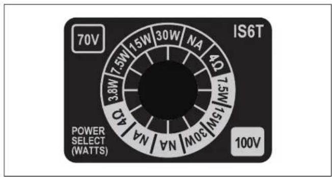
| Transformer Taps (70V) | 3.8W, 7.5W, 15W, 30W |
| Transformer Taps (100V) | 7.5W, 15W, 30W |
| Overload Protection | Two independent self-resetting poly switches |
| Safety Listings | UL-1480A, UL-2043, CSA-C22.2 No.205, NFPA-70, NFPA-90A |
| Finish Thickness (Optimal) | 1.0 - 1.5 mm (3/64 - 1/16 in) |
| Finish Thickness (Maximum) | 3 mm (1/8 in) |
| Warranty | 15 years limited |
| Box Contents | 1 speaker with cutout template, stainless steel screw set, 4x 1/16 in shims, 4x 1/8 in shims |
| Maintenance | Clean only with a dry cloth |
| Spare Parts and Repairability | Contact Sonance for authorized service; self-resetting poly fuses protect transducers |
Frequently Asked Questions - Invisible Series IS6T SONANCE
User questions about Invisible Series IS6T SONANCE
0 question about this device. Answer the ones you know or ask your own.
Ask a new question about this device
Download the instructions for your Loudspeaker in PDF format for free! Find your manual Invisible Series IS6T - SONANCE and take your electronic device back in hand. On this page are published all the documents necessary for the use of your device. Invisible Series IS6T by SONANCE.
USER MANUAL Invisible Series IS6T SONANCE
natural_image
Exterior view of a dark rectangular wall-mounted device with mounting brackets (no text or symbols visible)TABLE OF CONTENTS
2 Important Safety Instructions & Box Contents
3 Product Description & Features
4 70V Settings
5 Product Preparation & Planning
6 Project Management
7 Invisible Speaker Installation Detail
9 Retrofit Installation
10 New Construction Installation
13 Finishing Instructions
17 Technical Specifications
18 FAQ
20 Technical Assistance & Service
21 Warranty

Scan QR code for additional information and resources.
For technical support call (949) 492-7777 or visit
www.sonance.com/in-wall-in-ceiling/invisible-series
IMPORTANT SAFETY INSTRUCTIONS
This product is intended to be installed by professional AV integrators and installers only. This product manual is intended to serve as a general guideline for most applications. It is the installer's responsibility to ensure this product is installed in accordance with local building codes and regulations. Consult a local authority for specific requirements, regulations, and building codes of the jurisdiction in which this product is to be installed.
READ THIS DOCUMENT IN ITS ENTIRETY BEFORE ATTEMPTING USE.
- Read these instructions.
- Keep these instructions.
- Heed all warnings.
- Follow all instructions.
- Clean only with a dry cloth.
- Do not block any ventilation openings. Install in accordance with the manufacturer's instructions.
- Do not install near a heat source such as radiators, heat registers, stoves, fireplaces, or other apparatus (including amplifiers) that produce heat.
- Only use attachments/accessories specified by Sonance.
- To be installed in indoor locations only.
- Refer all servicing to qualified service personnel.
BOX & CONTENTS
(1) Invisible Speaker with Cutout Template
(1) Stainless Steel Screw Set
(4) 1/16" (1.6mm) Shims
(4) 1/8" (3.18mm) Shims
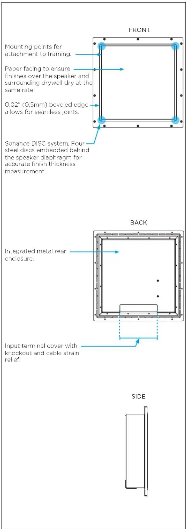
PRODUCT DESCRIPTION
The Sonance Invisible Series speakers featuring Motion Flex Technology offer a suite of advancements in speaker engineering that delivers unparalleled acoustic performance and installation enhancements that allow a wider range of applications with more consistent results. Together these performance and installation improvements redefine what is possible from an invisible speaker
This line of full-range speakers and woofers incorporate Wave Flex drive units, carbon fiber Air Flex woofers, and acoustically-isolated baffles, allowing for up to 180 degrees of smooth off-axis response.
The innovative Sonance DISC System enables non-destructive measurement of the finish thickness for consistent and repeatable installation results.
Sonance DSP amplifier presets should be used to maximize the performance of any Invisible Series system.
FEATURES
• In-wall or In-ceiling installation
- Compatible with 1/2" (12.5mm) & 5/8" (15mm) drywall using included shims. Supply your own shims for thicker substrates
- Finish-up-to or finish-over with up to 1/8" (3mm) flexible topping compound or finish material
• 170 degree hemispherical dispersion
- 30W multi-tap 70V/100V transformer with 4-ohm bypass and Sonance Laminated Core Technology for full-range, high-fidelity audio reproduction
- Embedded depth discs allow the installer to verify the finish material thickness with the optional DG-1 DISC System Depth Gauge (SKU 93491)
- Integrated, sealed metal rear enclosure for consistent installs in commercial applications
• UL 1480A and UL 2043 Listed
- Per-transducer poly fuses integrated into every speaker allow extra protection of each transducer from over-current.
• 15 year limited warranty.
70 VOLT APPLICATIONS
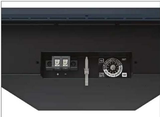
The Sonance Invisible Series IS6T includes a 70V/100V Sonance Laminated Core Transformer with an adjustable tap.
SETTING THE 70V TAP
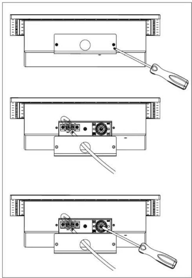
- Using a #2 Phillips head screwdriver remove the two screws securing the terminal cover plate.
- When using speaker wire without conduit, run the wire through the hole on the terminal cover plate. Wire needs to be clamped as required by national or local codes. Connect the wires to the terminal block being certain to connect the positive wire to terminal marked + and the negative wire to the terminal marked -.
When using conduit attach the conduit connector to the terminal cover plate then connect the wires to the terminal block being certain to connect the positive wire to terminal marked + and the negative wire to the terminal marked -.
- Using a flat head screwdriver set the transformer tap to the correct tap setting for your installation. We strongly recommend testing the system with music to determine the correct output level.
- Run the speaker wire from the first IS6T speaker in the chain to the amplifier terminals. Connect to either the right or left channel (+ and -) of the amp. (Sonance DSP 2-750 MKII shown in illustration).
NOTE: Amplifier bridging is NOT supported when in 70V configuration.
WARNING: Do not mount and finish over the speaker until you have selected the necessary tap setting to achieve the desired volume level. After selecting a given tap, play the speaker with an actual audio signal to verify the speaker provides adequate volume. If necessary, re-select a lower or higher tap setting.
natural_image
Technical line drawings of three mechanical assembly components with no visible text or symbols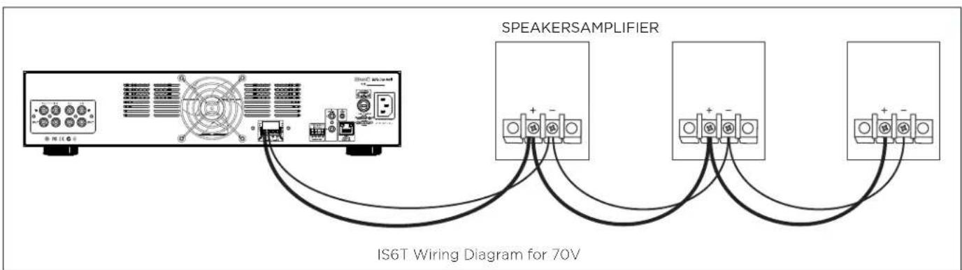
PRODUCT PREPARATION
Amplifier Selection
Sonance DSP Amplifiers are recommended for use with the IS6T speaker. When using the IS6T in 70V/100V, we recommend the Sonance DSP-2-750 MKII. These amps have preloaded curves to optimize the performance of Invisible Series speakers and woofers. Preconfigured curves for various finish types and thicknesses allow for effortless calibration without the need for additional measurement equipment. Sonance DSP Amplifiers are rated down to 4 Ohms and are stable to 2 Ohms. Never run more than two Invisible Speakers in parallel on one amplifier channel.
NOTE: Pay attention to Sonance IS speaker rated RMS power handling. Select an amplifier with max RMS watts per channel at 4 ohms that closely matches or is less than the IS speaker's rated power handling (see page 16). Damage to the speaker or installed finish may occur if the speaker is overdriven.
Wire Gauge - 70V/100V Systems
The most common wire used on commercial 70 volt systems is 18 gauge, 2 conductor, stranded, and jacketed without a shield. The wire starts at the amplifier location and is paralleled at each speaker location.
Wire length using 18 gauge is appropriate up to 700 feet with a 100 watt load. If you double the load (sum of your tap settings), you will reduce the footage by half, to 350 feet. Conversely, if you halve the load, you may double the acceptable wire length, i.e., a 50 watt load is safe over 1400 feet of 18 gauge. Stepping up to 16 gauge wire extends the allowable run length by approximately 35%. For example, a 100 watt load can go 700 feet on 18 gauge; the same load may be placed on 1100 feet of 16 gauge.
WIRE RESISTANCE IN OHMS VS. LENGTH OF CABLE RUN
| DISTANCE | 50'15.2m | 100'30.5m | 150'45.7m | 200'61m | 250'76.2m | 300'91.4m |
| 20 GAUGE | 0.86 1.73 | 2.59 3.45 | 4.32 5.18 | |||
| 18 GAUGE | 0.65 1.30 | 1.94 2.59 | 3.24 3.89 | |||
| 16 GAUGE | 0.43 0.85 | 1.28 1.71 | 2.14 2.56 | |||
| 14 GAUGE | 0.27 0.54 | 0.81 1.08 | 1.35 1.62 | |||
| 12 GAUGE | 0.17 | 0.34 | 0.51 | 0.68 | 0.85 | 1.02 |
Wire Gauge - Low Impedance Systems
When using the product in a low impedance system, the total wire resistance should be less than 10% of the speaker impedance. The speakers have a nominal 4 Ohm impedance, so your total wire resistance should be no more than 0.4 Ohms. Simply, the extra resistance from the wire will have a very negative affect on the sound quality of the speaker. The sound can be less dynamic, definition of bass frequencies can be reduced,
and in extreme cases, the high frequencies can be attenuated. Amplifier power is also wasted in the wire, reducing the maximum output level of the system. Please refer to the chart below when deciding on the appropriate wire gauge for your installation.
SPEAKER LOCATION
Invisible Series IS6T speakers have a 170 degree hemispherical dispersion pattern. This allows for a wide range of applications and installation locations. It is recommended that speakers be wall-mounted 7 feet (2.13 meters) or more above finished floor (AFF) or in-ceiling to avoid being punctured or damaged. Ensure that the speaker will not be covered by cabinetry, draperies, art, crown molding or anything that could cover or puncture the speaker. Face the Wave Flex Drive Unit away from the ceiling when installing in walls and away from the walls when installing in ceilings. Ensure that the back of the speaker has clearance and will not be adjacent to other building systems such as electrical, HVAC, pipes, fire sprinklers or others that could violate local building codes or adversely effect sound quality.
INSTALLATION ACCESSORIES
The use of space savers and preconstruction zip rings will assist in better coordination of trades and is recommended for best results. Space savers are a great way to reserve the precise dimensions and location of your Sonance Invisible Series speakers during the construction phase and will protect your speaker wire from getting lost within the wall or ceiling cavities. The space saver allows you to delay the installation of the actual invisible speaker to just prior to the finishing stage. This reduces the risk of damage or theft of speakers on the job site. If your project calls for large quantities of invisible speakers, you may use our preconstruction zip ring brackets as an easy guide for getting the perfect drywall cutout using a drywall zip tool. These can be installed in conjunction with the space savers or on their own and are to be used when drywall will be laid up directly over speaker locations. Zip rings are made-to-order, so please contact your Sonance representative for bulk pricing and availability.
SPACE SAVER PART NUMBERS
| IS-SAVER-S IS6T | 93492 4-pack |
FINISH MATERIALS
Prior to speaker installation, verify that the topping compound and final finish are flexible materials (slow-setting drywall mud/topping compound, wallpaper, acrylic-based Venetian plaster, thin wood veneer) and will not exceed 3mm (1/8").
NOTE: Our recommended target for optimal performance is between 1.0 and 1.5mm (about 1/16") of topping compound. Sound quality and installation durability will be adversely effected if too much
topping compound is applied. For wood veneer finishes, use only 20mil (0.5mm) veneer with paper backing.
NOTE: Do not use hard-setting or stiff materials over the surface of invisible speakers, such as fast-setting drywall mud (“hot mud”), genuine Venetian plaster, stucco, metal panels, tile, etc.
PRODUCT MANAGEMENT
Follow the installation instructions in this manual precisely to ensure outstanding speaker performance and true invisibility. To accomplish this flawlessly every time requires project management and close coordination with the drywall and finish trades along with the General Contractor and sometimes even the client. Here are some best practices that will prevent unmet expectations and expensive rework:
- After IS speakers are connected and screwed in but before any drywall mudding, taping, or finishing has started, schedule a walk-through with the client (or client's representative), the General Contractor, and the finish manager. Listen to every speaker for a couple minutes. This is the best opportunity to discover any anomalies or issues with invisible speaker performance.
- All in attendance should sign off on audio performance, speaker-by-speaker and room-by-room. Prepare a checklist like the example below and ask all parties to sign and date, acknowledging that the Sonance IS speakers perform to everyone's expectations.
- Review all installation steps and processes with the finish manager, emphasizing to cover the speakers with only enough flexible material to make the speakers disappear and no more. This typically ends
up being our recommended target of 1.0-1.5mm (or about 1/16"). Also emphasize the maximum of 3mm (or 1/8") finish thickness. Review our guidelines for recommended materials on page 5 and 14 with the finish manager.
- Use the Sonance DISC system and DG-1 depth gauge (SKU 93491) to validate the finish thickness. It is helpful to lend the gauge to the finish manager so that it can be used during the actual process.
- Once the finish material has completely dried, perform another room-by-room listening check of each speaker. If the speakers do not sound similar to the performance you heard prior to finishing, it is likely that the finish thickness exceeds the maximum of 3mm (1/8"). Now is the time to correct this by removing material.
- Remember: once the flooring is installed and the furniture is in place, it is too late to remove excess finish material from the Sonance IS speakers without significant cost, cleanup, and/or complexity.
Effective project management, sign-offs, and proactive communication with the trades will prevent unexpected results and provide consistent, beautiful installs that wow the client and end-users.
ADDITIONAL INFORMATION

For CAD files, detailed dimensions, and other technical information, scan the QR code below or visit www.sonance.com/in-wall-in-ceiling/invisible-series
EXAMPLE CHECKLIST:
| SONANCE INVISIBLE SPEAKERS AUDIO PERFORMANCE SIGN-OFF CHECKLIST | |||||
| PROJECT NAME____ ROOM #____ ROOM DESCRIPTION____ | |||||
| Model Serial # | PRE-FinishingAudio Test Approval | Measured FinishThickness | POST-FinishingAudio Test Approval | ||
| Speaker 1 | □ | mm | □ | ||
| Speaker 2 | □ | mm | □ | ||
| Speaker 3 | □ | mm | □ | ||
| Speaker 4 | □ | mm | □ | ||
| Speaker 5 | □ | mm | □ | ||
| Speaker 6 | □ | mm | □ | ||
| Audio Test Approval Signatures: | |||||
| Date: | |||||
INSTALLATION DETAIL - 16" (406MM) ON-CENTER
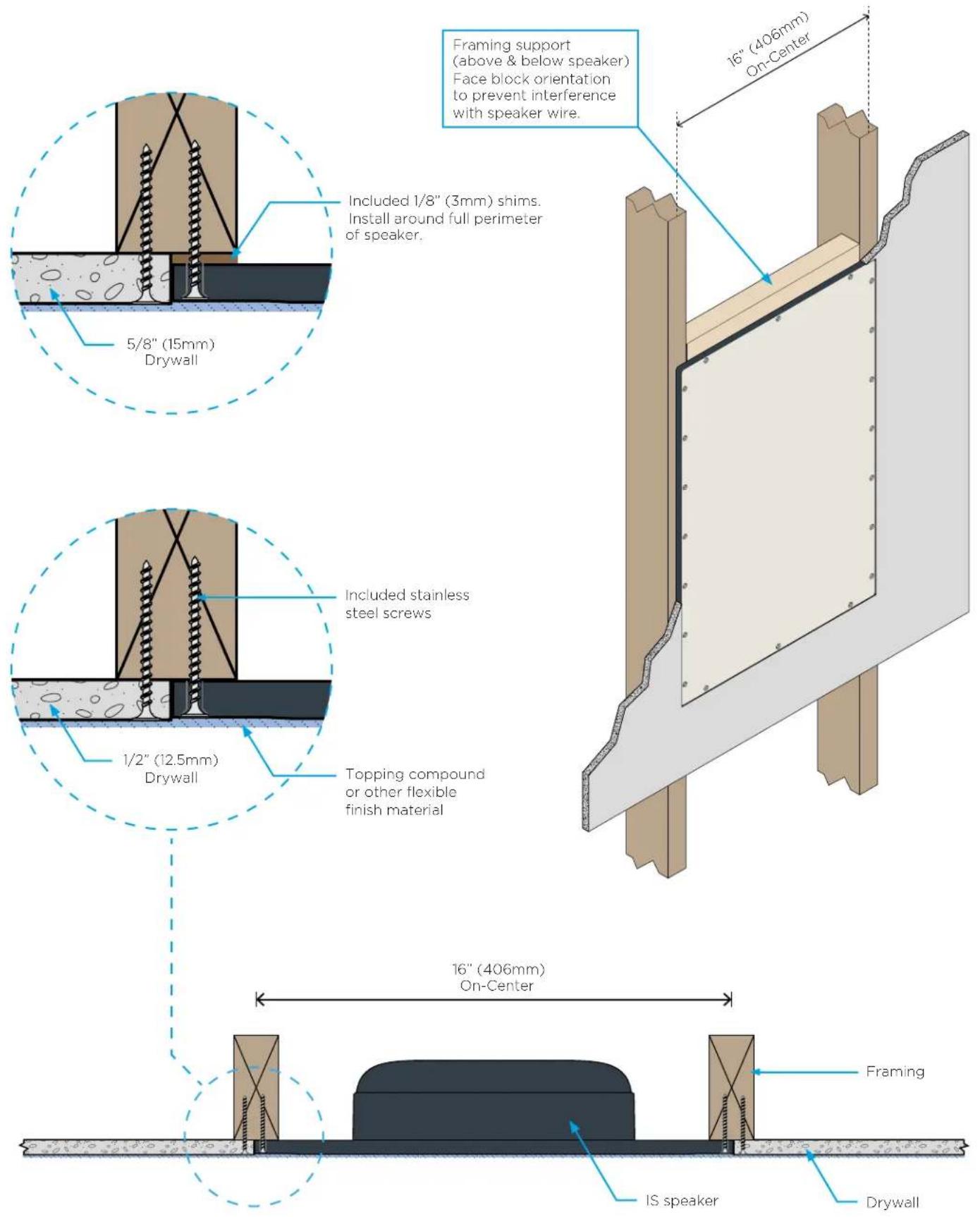
RETROFIT INSTALLATION
- Remove the included cutout template that is taped to the front of each speaker.

- Locate the studs in your install location and mark the centers of the studs/joists. Position and affix the template so that it is perfectly centered on both left and right studs.
- Mark around the template and remove. NOTE: We highly recommend you keep the cutout template. It is an important tool that will help identify the measurement locations for the Sonance DISC system during the finish validation phase.
- Before proceeding, perform an obstruction survey to be certain that there are no studs, conduit, pipes, HVAC ducts, pocket doors, etc. in the wall cavity that will interfere with the speaker.
- Cut the drywall using a drywall saw along the top and bottom and a utility knife along the stud centerlines. An oscillating power saw is recommended for faster, cleaner results.
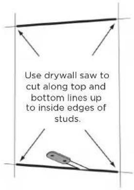
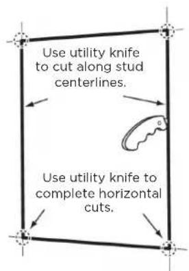
- Remove drywall from opening. This should expose only 3/4" (19mm) of each stud/joist or half of the stud/joist surface. Remove any exposed drywall nails or screws.
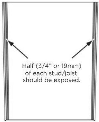
- Test-fit the speaker into the opening, verifying that the center diaphragm area is even with the drywall edges. If necessary, trim the edges of the drywall to properly accommodate the speaker.
- Run speaker wire from the amplifier and audio component location to the cut out holes for your speakers. See wiring chart on page 5.
- We recommend that you reinforce the top and bottom joint locations with a face-block-oriented 2x4 or 3/4" (19mm) plywood. See the construction diagrams on page 7 and STEP 2 on page 9. Ensure there is a flush, level surface around the full perimeter of the speaker location before proceeding.
- Proceed to STEP 9 on page 10.
NEW CONSTRUCTION INSTALLATION
- Run speaker wire from the amplifier and audio component location to desired speaker locations. See page 5 for wire gauge chart.
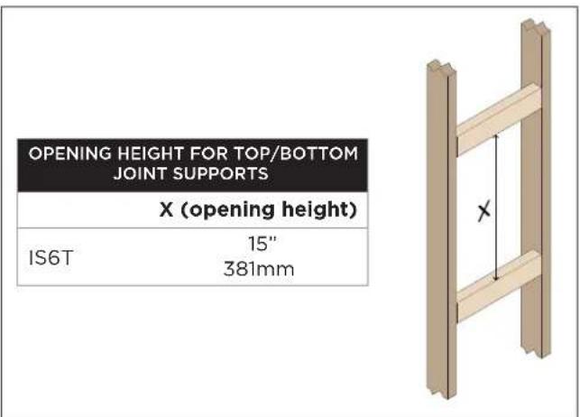
- We recommend that you reinforce the top and bottom joint locations with a face-block-oriented 2x4 or 3/4" (19mm) plywood. See the construction diagram on page 7 and the chart below for opening height dimensions. Product dimensional drawings are available on www.sonance.com. Ensure there is a flush, level surface around the full perimeter of the speaker location before proceeding.
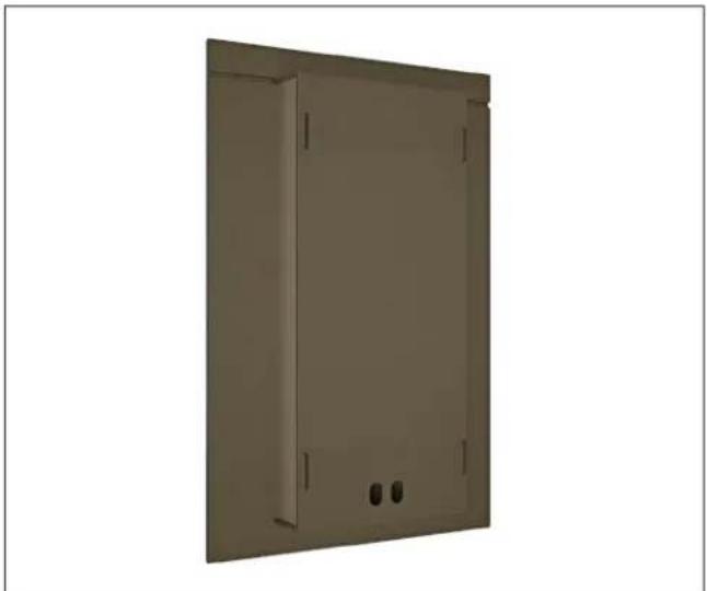
- Place space saver, preconstruction zip ring bracket, or both in desired speaker location. See page 5 for when to use space savers and zip rings. Space savers are recommended for every new construction project. Zip rings are recommended as a time-saver on very large projects with dozens of invisible speakers.
natural_image
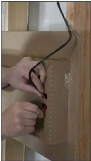
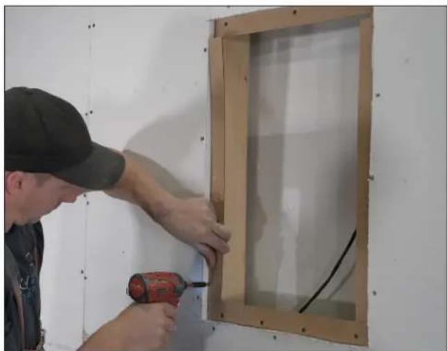
Exterior view of a beige rectangular metal enclosure with mounting holes and a small outlet (no text or symbols)- Use the wire management built into the space saver/zip ring to keep your cables in place. With the aid of a level, screw the space saver/zip ring to the studs, making sure it's centered horizontally.
natural_image
Close-up of hands installing or adjusting a cable on a cardboard box (no visible text or symbols)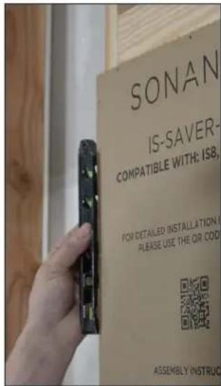
-
Complete drywall installation to the rest of the room including the surface around the speakers. NOTE: Sonance recommends using the included stainless steel screws around the speaker locations. This is to avoid interfering with the Sonance DISC system depth gauge operation after install. Though this is not required, it will improve the accuracy of finish thickness measurements later on.
-
Remove the space saver, if applicable. Hold onto the speaker wire attached to the back and pull it through the opening, being careful not to damage the surrounding drywall. The space saver can be kept for future installations or recycled.
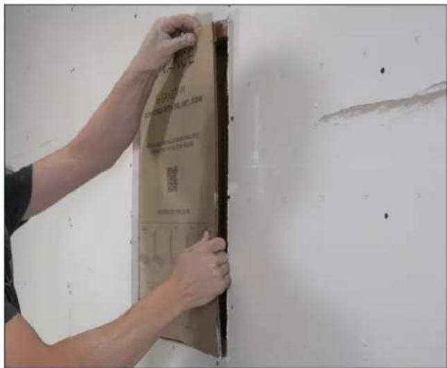
- OPTIONAL: If the zip ring was also used, cut the drywall at the speaker location using a zip tool and the zip ring as a guide. Be sure to cut along the outside edge of the zip ring. It will stay in place permanently.
- Install shims to your framing as needed. Half inch (12.5mm) drywall does not require shims in most cases. If you are using a thicker substrate such as 5/8" (15mm) drywall, we include a thick 1/8" (3mm) shim to bring the speaker flush to the installation surface. We also include a full set of thin 1/16" (1.6mm) shims to make installation in a variety of substrates easier.
NOTE: When using shims, make sure all 4 speaker edges (top, bottom, and sides) are supported for a flush install surface around the entire perimeter of the speaker.
natural_image
Worker installing or repairing a wall-mounted panel with a tool, no visible text or symbols- Connect the speaker wire from your wall or ceiling to the wire terminals on the speaker and set the tap switch appropriately.
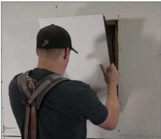
- Place the speaker into the opening. In a ceiling installation, do not hold the speaker in the center of the diaphragm. Hold at the edge of the frame and get assistance from a helper. Secure the speaker using one of the included stainless steel screws in each corner (use at least 4 screws total for this step).
NOTE: The best practice is to use stainless screws to secure the drywall surrounding the speaker as well. Unlike standard drywall screws, these are non-magnetic which will improve the accuracy of the Sonance DISC system later on in the finishing stage.
natural_image
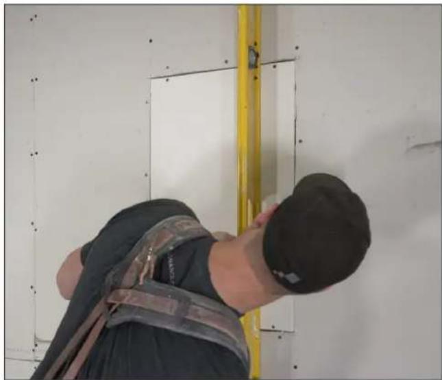
Person installing or adjusting a whiteboard on a wall, wearing a cap and backpack (no visible text or symbols)- Ensure the center of the speaker diaphragm (not the recessed edges) is flush with the surrounding drywall. Adjust shims if necessary.
natural_image
Person installing or inspecting a wall-mounted panel, wearing safety harness and cap (no visible text or symbols)-
IMPORTANT: Test the speaker with an audio source at moderate listening levels to ensure it functions properly before completing the installation. Follow the guidelines on this page carefully.
-
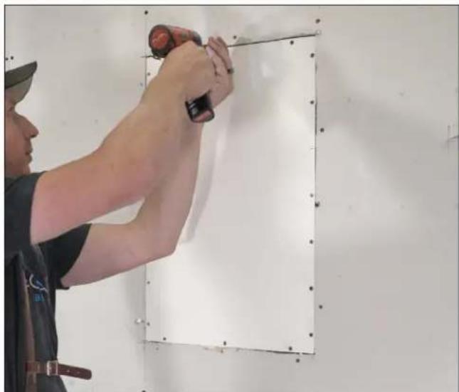
Secure the speaker to the surface with the remaining stainless steel screws along all four sides. Do not over-tighten.
natural_image
Person installing or adjusting a white panel on a wall, no visible text or symbolsPRE-FINISHING TESTING GUIDELINES
Once a finish is applied to an invisible speaker, it will be too late to go back and fix any audio connection or installation problems.
Installation Fit Test
Lightly place a straight edge across the face of the speaker to verify that the diaphragm of the speaker is co-planar with the surrounding drywall and has been installed correctly. Adjust shims if necessary. It is normal for the beveled edge of the speaker to be recessed from adjacent drywall.
Audio Test
Connect a high-quality audio source and Sonance amplifier to the installed invisible speaker for best results. Adjust the output for a moderate volume level consistent with how the speakers will be used in the space. Play music to check for overall fidelity and listen for any buzzes or rattles. We also recommend a slow tone sweep from 20Hz to 5kHz to help pinpoint any buzzing that could be caused from loose studs/screws/drywall, cable vibration, or rattling of outlets, lighting components, construction fixtures, etc.
Fix any installation or audio issues before moving on to the next steps.
We highly recommend active project management practices as described on page 6. Only after passing these testing guidelines should you proceed to the finishing stage.
FINISHING INSTRUCTIONS
NOTE: Drywall finishes can range in various levels of smoothness. For invisible speaker installations, we recommend at least a level four finish where drywall seams are all feathered out and sanded. For best results, we recommend a level five finish where the entire wall plane is skim-coated and sanded for smooth consistency.
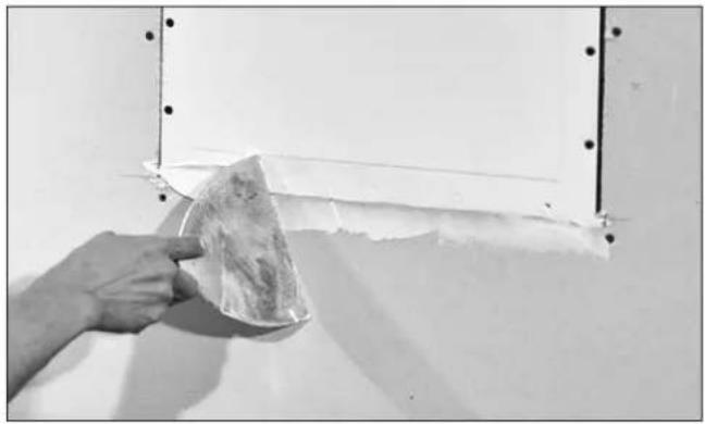
- Fill the gap between speaker and drywall with 20 minute fast-setting joint compound ("hot mud").
natural_image
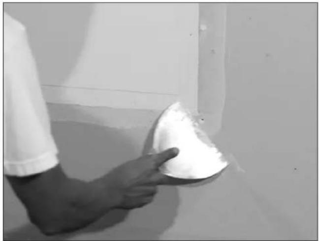
Hand applying a material to a wall corner with metal framing (no text or symbols visible)- Feather all edges.
natural_image
Person holding a white dome-shaped object near a wall, no visible text or symbols- Allow hot mud to set slightly before applying mesh tape.
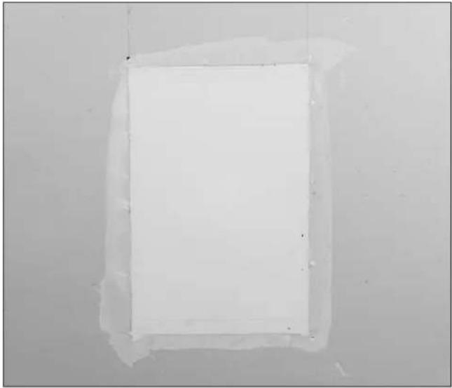
natural_image
Plain white rectangular object with a thin border, no visible text or symbols- Place mesh tape over the drywall seams. Overlap tape slightly.
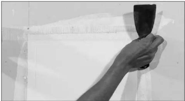
natural_image
Hand holding a black tool against a white wall, no visible text or symbols- Do not tape over the raised portion of the speaker.
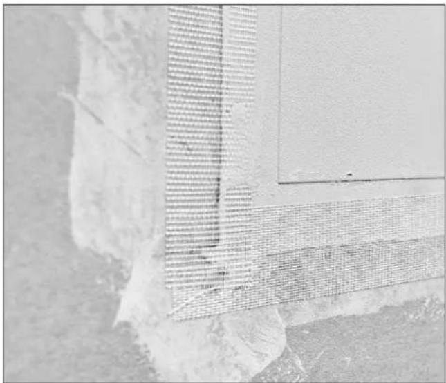
natural_image
Aerial view of a building with a large wall and adjacent structure, showing no visible text or symbols.- Allow hot mud to fully cure and harden.
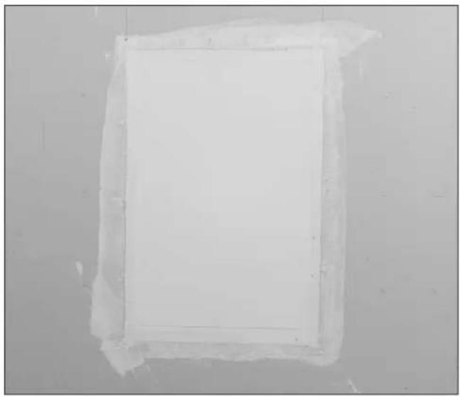
natural_image
Plain white rectangular frame with a thin border, no text or symbols visible- Once hot mud has fully cured, cover joints with slow-setting compound.
natural_image
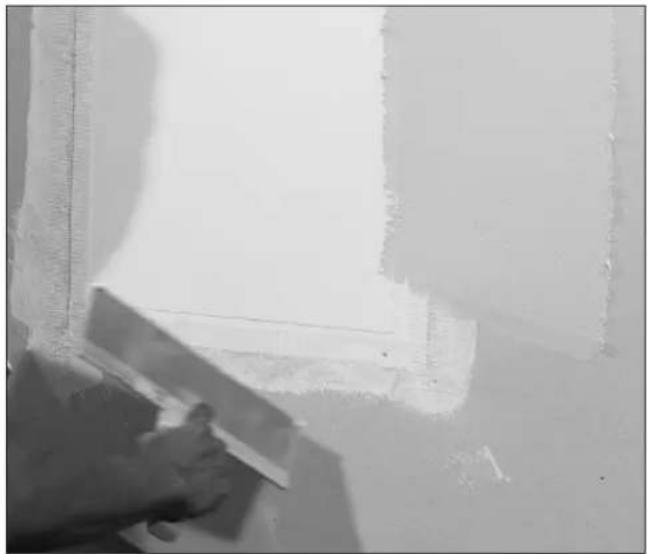
Close-up of a hand using a tool to clean or store floor tiles near a window (no visible text or symbols)NOTE: DO NOT use fast-setting drywall compound ("hot mud") to cover the speaker; it is not flexible enough to provide a durable finish for invisible speakers. Instead we recommend a lightweight all-purpose joint compound to cover joints and feather up to the surface of the speaker. Lightweight, easy-sand topping compound should be used for covering the speaker.
RECOMMENDED DRYWALL COMPOUNDS
| STEP 1Filling gaps | 20-minute All-Purpose Joint Compound (“Hot Mud”) |
| STEP 7Covering joints | Slow-setting Lightweight All-Purpose Joint Compound |
| STEP 10, 14Covering the speaker | Slow-setting Lightweight Easy-Sand Topping Compound |
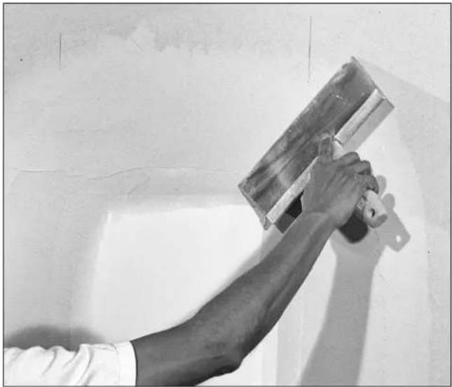
- Feather all surfaces around the joints and up to the raised portion of the speaker diaphragm.
natural_image
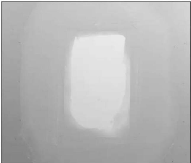
Person using a metal trowel to apply or apply on a wall (no text or symbols visible)- Allow first coat to fully cure. This can take 12-24 hours.
natural_image
Grayscale image of a bright, indistinct rectangular light source against a neutral background (no text or symbols)IMPORTANT: If a perfectly flat finish is achieved at this point, you may opt to proceed to the priming and painting phase. This is what we refer to as a "Finish Up To" installation. In this case, we recommend multiple layers of paint to achieve a shadow-less, even blending of color.
We highly recommend a "Finish Over" process where an additional skim coat is applied over the entire speaker and blended into the surrounding wall plane. A Finish Over process typically takes less time to complete versus Finish Up To because fewer layers of paint are needed. And with the skim coat over the entire surface of the speaker and wall, it's much easier to achieve perfect invisibility.
FINISH THICKNESS GUIDELINES
Sound quality and installation durability will be adversely effected if finish materials are applied too thick.
TOTAL FINISH THICKNESS FOR OPTIMAL PERFORMANCE: 1.0mm to 1.5mm (3/64" to 1/16")
MAXIMUM TOTAL FINISH THICKNESS: 3mm (1/8")
Validate finish thickness using the Sonance DG-1 depth gauge (SKU 93491).
Do not use hard-setting or stiff materials over the surface of invisible speakers, such as fast-setting drywall mud ("hot mud"), genuine Venetian plaster, stucco, metal panels, tile, etc. Use only flexible materials to finish invisible speakers.
When using flexible sheet materials such as wallpaper or veneer, ensure that the total thickness of any drywall compound, adhesives, and the finishing substrate itself does not exceed 3mm (1/8"). For wood veneer finishes, use only 20mil (0.5mm) veneer with paper backing.
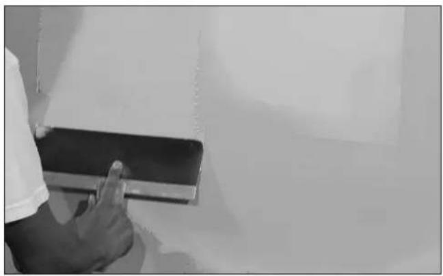
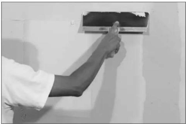
- Apply a second coat of topping compound covering the entire surface of the speaker and all adjoining surfaces.
natural_image
Person in white shirt pointing at a tablet on a plain surface (no visible text or symbols)- Compound buildup on the active surface of the speaker should not exceed 3mm (1/8").
natural_image
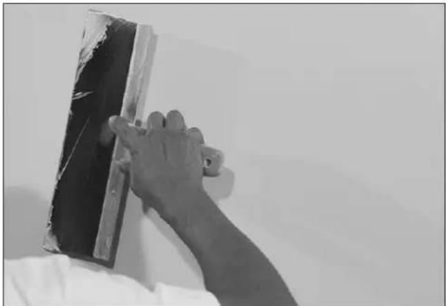
Person using a spray gun to clean or store air by a wall (no text or symbols visible)- Detail the compound to minimize tool marks.
natural_image
Close-up of a hand using a squeegee to apply material on a wall (no text or symbols visible)-
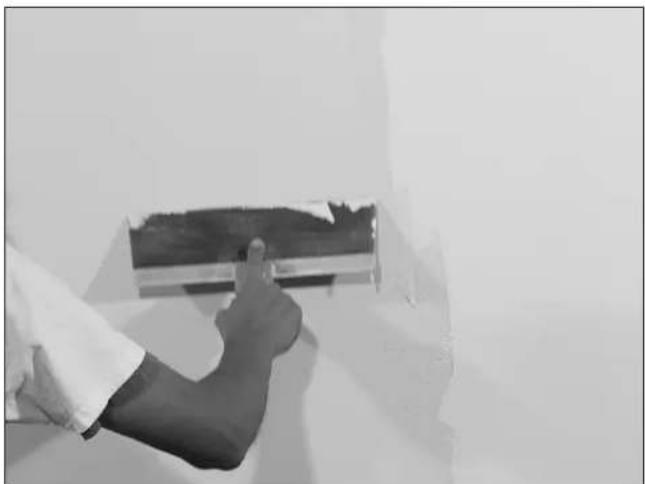
Allow each layer to fully cure. This can take 12-24 hours.
-
Build more coats as necessary to achieve desired finish. Each successive coat should be thinner than the last. The final coat should be a very light skim coat application.
natural_image
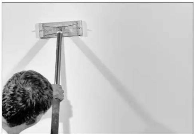
Person giving a thumbs-up gesture in front of a wall-mounted air conditioner unit (no visible text or symbols)- After final coat is applied and has dried, use a manual pole sander or block sander on entire wall (do not use a power sander as this could damage the surface of the speaker). Be careful not to sand down into the surface of the speaker. This could damage the paper which makes perfect blending very difficult to achieve. Wall surface should show no signs of a speaker.
natural_image
Person using a broom to clean or paint the ceiling (no text or symbols visible)- Validate the finish thickness using the Sonance DISC system and DG-1 depth gauge (SKU 93491).
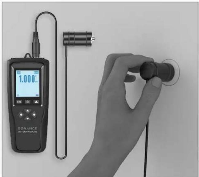
- The final step is to once again perform an audio test. Listen to each speaker and verify that audio quality and performance have not significantly changed since your initial listening test just prior to the finishing stage. Now is the best time to fix any audible anomalies or surface imperfections.
After listening validation, your Sonance Invisible speaker installation is now complete. From this point, follow your normal method for final finishing with flexible materials such as paint, wallpaper, veneer, and so on.
TECHNICAL SPECIFICATIONS

natural_image
Plain white square with no visible text, symbols, or features.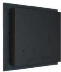
natural_image
Exterior view of a black wall-mounted electronic device (no visible text or symbols)Frequency Range (-3dB) 50Hz-20kHz
Power Capacity 100 Watts (RMS)
Nominal Sensitivity 84dB
Dispersion 170° Hemispherical up to 10kHz
Rated Impedance 4 Ohm
Transformer 30W with Sonance Laminated Core Technology
Transformer Taps Primary Taps (70V): 3.8W, 7.5W, 15W, 30W
Primary Taps (100V): 7.5W, 15W, 30W
4 Ohm Bypass
Overall Dimensions (WxHxD) 16.10" x 16.10" x 3.86" (409mm x 409mm x 98mm)
Mounting Depth 3.39" (86mm)
Product Weight 18.41 lbs. (8.35kg) / Each
Shipping Weight 24.25 lbs (11kg) / Each
Unit of Measure 40198 Each
LF Driver 98in² (633cm²) Air Pulse Diaphragm 6.5" (165mm)
Carbon Fiber Woofer
HF Driver 20in² (127cm²) Bending Wave Diaphragm 1.75" (44mm)
Voice Coil
Overload Protection Two Independent Self-Resetting Poly Switches
Safety Agency UL-1480A, UL-2043, CSA-C22.2 No.205, NFPA-70, and
NFPA-90A
FREQUENTLY ASKED QUESTIONS
Can Invisible Series speakers be installed in the ceiling or just in walls?
Sonance IS speakers can be installed in both walls and ceilings.
Where is the best place to locate the speakers?
If installing into walls, make sure they are at least 7' (2.13m) from the floor. In ceilings, evenly space the speakers for optimal coverage, and avoid corners if possible. Contact Sonance Tech Support / Design Services for help with speaker layout planning.
What is the minimum depth requirement?
Minimum depth without enclosure = \~2.75" (70mm)
Minimum depth with enclosure = -3.5" (90mm)
Can IS speakers be used in a plenum space?
Only models with a "T" suffix such as the IS8T are rated for plenum use (UL2043). The standard models (IS6/IS8/IS10/IS10W) are not plenum rated.
Can these speakers be installed in a T-Bar ceiling?
Theoretically yes. Consult with the manufacturer of the T-Bar ceiling in question to ensure the max load is within safe limits for the aggregate weight of the IS speakers you wish to install.
Can these be used outside?
Sonance invisible speakers are not outdoor rated and should not be used outside.
Can these be used in high heat or high humidity applications?
Invisible speakers should not be directly exposed to high heat or humidity. However you may use finishing materials that are rated for high heat and humidity exposure, provided that they form a barrier that prevents exposure to the speakers. We highly recommend you perform a mock-up trial of the finish materials, speaker, and environment to validate the performance long-term.
What finish materials can I use with invisible speakers? Can these be covered with wallpaper or wood veneer?
Use flexible materials such as: slow-setting, lightweight drywall compounds, wallpaper, wood veneer, vinyl veneer, acrylic-based venetian plaster. See page 14 for more details.
Are there materials that should not be used to cover the speakers?
Any material that is stiff, inflexible, or exceeds 3mm (1/8") in total thickness over the speaker diaphragm such as tile, metal sheet, stone veneer, true Venetian plaster, stucco, etc. These are not compatible with invisible speakers. The stiffness of materials like these restrict movement and result in lack of bass and muffled sound.
How much finish material can go over the speaker?
We recommend 1.0mm to 1.5mm for optimal performance. The maximum limit is 3mm (1/8").
How can I tell how much finish material is covering the speaker?
Use the Sonance DG-1 depth gauge (SKU 93491) to measure actual finish thickness covering Sonance invisible speakers.
What is the DISC system?
The Sonance DISC System provides a highly accurate method for non-destructively quantifying the thickness of a finish applied on top of a Sonance invisible speaker diaphragm. The Sonance DG-1 handheld depth gauge uses a magnetic sensor to measure the distance between the top of the finished speaker and steel discs embedded in all four corners behind the speaker diaphragm of Sonance Motion Flex Invisible Speakers.
What if I add too much finish material?
Prior to the final finishing stage (such as painting), sand down the wall or ceiling surface and measure the finish thickness using the DG-1 depth gauge. Repeat as necessary until you measure 3mm or less. We recommend 1.0mm and 1.5mm for optimal performance.
Is there a benefit to "Finish Up To" rather than "Finish Over"?
There is no practical benefit to a Finish Up To style finish. In fact, we recommend Finish Over because it typically takes less installation time and results in a more seamless, shadowless final finish. Furthermore, IS speakers are optimized for about 1.0mm to 1.5mm of finish material for best performance.
What happens if the mud or finish cracks?
Mud/finish cracks are indicative of either an improperly applied finish or invisible speakers that have been regularly overdriven. Though the integrated poly fuses mitigate against damage, they cannot protect against every type of abuse. Remember, just like traditional speakers, invisible speakers have their limit. However, the difference is when a traditional speaker fails due to over-exertion, only the speaker is damaged; whereas with invisibles, the finish can sometimes be damaged as well.
Though it is rare, if a crack occurs, Sonance will help troubleshoot the issue on a case-by-case basis. We typically start by inspecting the finish process. In most cases, the finish was applied too thick (outside of our specifications). With our new DISC system, we have the ability to prevent these types of failures before they even happen by identifying and correcting at the installation phase. This is why we highly recommend taking advantage of the DISC system during installation to prevent problems down the road.
Can I use other than Sonance DSP amplifiers?
Yes, but we highly recommend Sonance DSP amps due to the built-in DSP preset curves. Pay close attention to Sonance IS speaker rated RMS power handling and select an amplifier whose maximum RMS watts per channel closely matches or is less than the IS speaker's rated power handling. If the amplifier's power capabilities exceed those of the speakers, damage to the speaker or installed finish may occur if the speaker is overdriven. For Sonance IS woofers and subwoofers, always use a Sonance DSP amplifier to drive them.
I lost the screws. What is the spec or do I have to buy them from Sonance?
Use stainless steel #6 drywall screws in the appropriate length depending upon drywall/installation substrate panel thickness and local codes.
I lost the shims. How can I get more? Do I have to buy them from Sonance?
Use standard drywall shims available from your local hardware store.
Is there a protection circuit built into the speaker or do they need to be added?
Every full-range speaker in the lineup (IS6T/IS8T) has dual, self-resetting poly fuses: one dedicated to each transducer. The woofers have a single poly fuse. If a speaker is overdriven, one or both of the poly fuses will trip, and the transducers will cease to make sound which protects both the driver and the installation surface from damage in overdrive conditions. After a few minutes, the fuses will reset, and the speakers will perform as normal. If the poly fuses are tripping, that's a sign that the speakers are being overdriven, and you should decrease the volume. If you want more volume, add additional invisible speakers to your space.
What is the warranty on IS invisible speakers, and what does the warranty cover?
The 15 Year limited warranty covers the cost to replace the speaker(s) and refinishing up to level 5 drywall finish.
CERTIFICATIONS
SAFETY AGENCY COMPLIANCE
Sonance Invisible Series IS6T speaker models meet the following standards:
UL-1480A: Speakers for Fire Protective Signaling Systems.
UL-2043: Fire Test for Heat and Visible Smoke Release for Discrete Products and their Accessories Installed in Air Handling Spaces
CSA-C22.2 No.205: Signaling Equipment for General Signaling and Fire Alarm Signaling, Canada
Shall be installed in accordance with:
NFPA-70: National Electric Code
NFPA-90A: Installation of Air Conditioning and Ventilation
CSA C22.1: Canadian Electrical Code

LISTED
S8522
23WG


TECHNICAL ASSISTANCE AND SERVICE
The Technical Assistance Department at Sonance is available at (949) 492-7777 to answer any questions concerning the operation and installation of your speakers between the hours of 7:00 AM and 5:00 PM Pacific time, Monday through Friday, except holidays.
In the event your unit should need repair or service, you may return the unit to your authorized dealer or use the following guidelines:
PLEASE KEEP ORIGINAL PACKAGING WHEN POSSIBLE.
-
Be prepared to state the model number and / or serial number, date of purchase, and dealer's name and address when calling.
-
Contact Sonance directly at (949) 492-7777 or at www.sonance.com. YOU MUST HAVE PRIOR AUTHORIZATION TO RETURN YOUR UNIT.
-
If you are returning the product directly to Sonance, call us to obtain a return authorization number (RMA) before shipping.
-
Ship the product via United Parcel Service, Federal Express, or other package delivery service. Please do not use the U.S. Postal Service.
-
Include the return authorization number on the shipping label. Please do not write the RMA number directly on the carton.
-
Ship to: Attn: Quality Assurance Department RMA# (include RMA number here) Sonance 11016 Mulberry Ave. Suite B Fontana, CA 92337
LIMITED FIFTEEN (15) YEAR WARRANTY
Sonance warrants to the first end-user purchaser that this Sonance-brand product ("Product"), when purchased from an authorized Sonance Dealer/Distributor, will be free from defective workmanship and materials for the period stated below. Sonance will at its option and expense during the warranty period, either repair the defect or replace the Product with a new or re-manufactured Product or a reasonable equivalent.
EXCLUSIONS
TO THE EXTENT PERMITTED BY LAW, THE WARRANTY SET FORTH ABOVE IS IN LIEU OF, AND EXCLUSIVE OF, ALL OTHER WARRANTIES, EXPRESS OR IMPLIED, AND IS THE SOLE AND EXCLUSIVE WARRANTY PROVIDED BY SONANCE. ALL OTHER EXPRESS AND IMPLIED WARRANTIES, INCLUDING THE IMPLIED WARRANTIES OF MERCHANTABILITY, IMPLIED WARRANTY OF FITNESS FOR USE, AND IMPLIED WARRANTY OF FITNESS FOR A PARTICULAR PURPOSE ARE SPECIFICALLY EXCLUDED.
No one is authorized to make or modify any warranties on behalf of Sonance. The warranty stated above is the sole and exclusive remedy, and Sonance's performance shall constitute full and final satisfaction of all obligations, liabilities, and claims with respect to the Product.
IN ANY EVENT, SONANCE SHALL NOT BE LIABLE FOR CONSEQUENTIAL, INCIDENTAL, ECONOMIC, PROPERTY, BODILY INJURY, OR PERSONAL INJURY DAMAGES ARISING FROM THE PRODUCT, ANY BREACH OF THIS WARRANTY, OR OTHERWISE.
This warranty statement gives you specific legal rights, and you may have other rights which vary from state to state. Some states do not allow the exclusion of implied warranties or limitations of remedies, so the above exclusions and limitations may not apply. If your state does not allow disclaimer of implied warranties, the duration of such implied warranties is limited to period of Sonance's express warranty. Your Product Model and Description: IS6T Invisible Speakers. Warranty Period for this Product: Fifteen (15) years from the date on the original sales receipt or invoice or other satisfactory proof of purchase. Additional Limitations and Exclusions from Warranty Coverage: The warranty described above is nontransferable, applies only to the initial installation of the Product, does not include installation of any repaired or replaced Product, does not include damage to allied or associated equipment which may result for any reason from use with this Product, and does not include labor or parts caused by accident, disaster, negligence, improper installation, misuse (e.g. overdriving the amplifier or speaker, excessive heat, cold or humidity, mishandling, etc.), or from service or repair which has not been authorized by Sonance. Obtaining Authorized Service: To qualify for the warranty, you must contact your authorized Sonance Dealer/Installer or call Sonance Customer Service at (949) 492-7777 within the warranty period, must obtain a return merchandise number (RMA), and must deliver the Product to Sonance shipping prepaid during the warranty period, together with the original sales receipt, or invoice or other satisfactory proof of purchase.
SONANCE
©2020 Sonance. All rights reserved. Sonance is a registered trademarks of Dana Innovations. Due to continuous product improvement, all features and specifications are subject to change without notice. For the latest Sonance product specification information visit our website: www.sonance.com
SONANCE • 991 Calle Amanecer • San Clemente, CA 92673 USA PHONE: (949) 492-7777 • FAX: (949) 361-5151 • Technical Support: (949) 492-7777 • www.sonance.com 336-0063 v2.21
- TABLE OF CONTENTS
- IMPORTANT SAFETY INSTRUCTIONS
- READ THIS DOCUMENT IN ITS ENTIRETY BEFORE ATTEMPTING USE.
- BOX & CONTENTS
- PRODUCT DESCRIPTION
- FEATURES
- VOLT APPLICATIONS
- SETTING THE 70V TAP
- PRODUCT PREPARATION
- Amplifier Selection
- Wire Gauge - 70V/100V Systems
- Wire Gauge - Low Impedance Systems
- SPEAKER LOCATION
- INSTALLATION ACCESSORIES
- FINISH MATERIALS
- PRODUCT MANAGEMENT
- RETROFIT INSTALLATION
- NEW CONSTRUCTION INSTALLATION
- PRE-FINISHING TESTING GUIDELINES
- Installation Fit Test
- Audio Test
- FINISHING INSTRUCTIONS
- FINISH THICKNESS GUIDELINES
- TECHNICAL SPECIFICATIONS
- FREQUENTLY ASKED QUESTIONS
- Can Invisible Series speakers be installed in the ceiling or just in walls?
- Where is the best place to locate the speakers?
- What is the minimum depth requirement?
- Can IS speakers be used in a plenum space?
- Can these speakers be installed in a T-Bar ceiling?
- Can these be used outside?
- Can these be used in high heat or high humidity applications?
- What finish materials can I use with invisible speakers? Can these be covered with wallpaper or wood veneer?
- Are there materials that should not be used to cover the speakers?
- How much finish material can go over the speaker?
- How can I tell how much finish material is covering the speaker?
- What is the DISC system?
- What if I add too much finish material?
- Is there a benefit to "Finish Up To" rather than "Finish Over"?
- What happens if the mud or finish cracks?
- Can I use other than Sonance DSP amplifiers?
- I lost the screws. What is the spec or do I have to buy them from Sonance?
- I lost the shims. How can I get more? Do I have to buy them from Sonance?
- Is there a protection circuit built into the speaker or do they need to be added?
- What is the warranty on IS invisible speakers, and what does the warranty cover?
- CERTIFICATIONS
- SAFETY AGENCY COMPLIANCE
- TECHNICAL ASSISTANCE AND SERVICE
- PLEASE KEEP ORIGINAL PACKAGING WHEN POSSIBLE.
- LIMITED FIFTEEN (15) YEAR WARRANTY
- EXCLUSIONS
- SONANCE
Brand : SONANCE
Model : Invisible Series IS6T
Category : Loudspeaker