Reference RSA 120 - Receiver INFINITY - Free user manual and instructions
Find the device manual for free Reference RSA 120 INFINITY in PDF.

| Product Type | Stereo Receiver |
| Brand | Infinity |
| Model | Reference RSA 120 |
| Dimensions (W x H x D) | 17.0 x 5.0 x 14.0 inches (432 x 127 x 356 mm) |
| Weight | 12.0 lbs (5.4 kg) |
| Power Supply | 120V AC, 60Hz |
| Power Consumption | 350 W (maximum) |
| Output Power (RMS) | 100 W per channel into 8 ohms (20 Hz - 20 kHz, 0.08% THD) |
| Total Harmonic Distortion | < 0.08% |
| Frequency Response | 20 Hz - 20 kHz ±0.5 dB |
| Signal-to-Noise Ratio | 95 dB (A-weighted) |
| Input Sensitivity (Line) | 150 mV |
| Input Impedance | 47 k ohms |
| Tuner Bands | AM / FM |
| Audio Inputs | CD, Tape, AUX, Phono (MM) |
| Audio Outputs | Speaker A / B, Rec Out, Headphone (1/4") |
| Speaker Impedance | 4 - 16 ohms |
| Dimensions (Carton) | 20.5 x 8.5 x 16.0 inches |
| Weight (Carton) | 14.0 lbs |
| Package Contents | Receiver, AM loop antenna, FM antenna, remote control, batteries, power cord, user manual |
| Warranty | 2 years limited |
| Maintenance | Clean with a soft, dry cloth. Do not use solvents. |
| Safety | Do not expose to rain or moisture. Disconnect power when not in use. |
| Reparability | Contact authorized service center for repairs. |
Frequently Asked Questions - Reference RSA 120 INFINITY
User questions about Reference RSA 120 INFINITY
0 question about this device. Answer the ones you know or ask your own.
Ask a new question about this device
Download the instructions for your Receiver in PDF format for free! Find your manual Reference RSA 120 - INFINITY and take your electronic device back in hand. On this page are published all the documents necessary for the use of your device. Reference RSA 120 by INFINITY.
USER MANUAL Reference RSA 120 INFINITY
OWNER'S MANUAL for your Infinity Reference Standard Automotive Amplifiers
Models RSA 120, RSA 250, RSA 4•40, RSA 450

text_image
& ®TABLE OF CONTENTS
Introduction 3
Associated Components 3
Mounting the Amplifier 4
Wiring 6
Connecting the Amplifier, Stereo Mode: (RSA 120, 250 and 450) 8
Connecting the Amplifier, Mono Mode: (RSA 120, 250 and 450) 9
Connecting the Amplifier: 4-Channel Mode, 4x40 Watts (RSA 4•40 only) .....11
Connecting the Amplifier: 2-Channel Mode, 2x80 Watts (RSA 4•40 only)....12
Connecting the Amplifier: 3-Channel Mode, 1x80 Watts & 2x40 Watts (RSA 4•40 only) ..... 13
Power Connections 14
Operating the System 15
Setting the Input Sensitivity Control....15
Troubleshooting Guide....16
To Insure Continued Enjoyment From Your RSA Amplifier ....16
OWNER'S MANUAL, INFINITY REFERENCE STANDARD AUTOMOTIVE AMPLIFIERS
MODELS RSA 120, RSA 250, RSA 4·40, RSA 450
INTRODUCTION:
Congratulations. You now own one of the finest amplifiers available for automotive use. The research, design and craftsmanship of this amplifier reflect our goal of providing the same high level of quality for the car as we do for the home. In order to realize the full potential of this product, proper installation and operation are essential. It is, therefore, advised that you read through this manual before beginning the installation, and if you are unsure of your ability to perform the installation yourself, have the amplifier installed by a qualified automotive installer.
The installation should be planned ahead of time to insure the best success and performance. Pay close attention to all cautionary statements and installation tips provided in this manual. Work slowly and carefully, and double-check the installation before operating the system. Paying close attention to small details now will help provide years of trouble-free performance.
ASSOCIATED COMPONENTS:
All Infinity Reference Standard Amplifiers are compatible with virtually every high-quality mobile stereo product on the market. However, to fully realize their potential, please observe the following guidelines.
The amplifiers will accept the low-level (preamp) output of almost any radio/cassette deck, CD player, preamp EQ or electronic crossover designed for the car. The amplifier's sensitivity control will allow optimum matching of these components for minimal system noise. (Refer to the section on operating the system for more information.) If the front-end unit you are using does not have preamp outputs (usually a pair of RCA jacks labeled "preamp out," or "aux out," or similar), it will be necessary to use an attenuation box (available from your dealer) to drop the level of the speaker outputs from the front-end unit before connecting them to the inputs of the amplifier. This is necessary to avoid overloading the amplifier's input stages.
Use of high quality speakers, capable of handling the rated power output of the amplifier(s) used, is also very important. When the amplifiers are operated in the stereo mode, they are stable into speaker loads as low as 2 ohms. If two pairs of speakers are to be used in parallel with each other, driven by one amplifier, each speaker's impedance must be at least 4 ohms to keep the overall impedance above 2 ohms. Impedance loads of less than 2 ohms will probably trigger the amplifier's protection circuits, shutting down the amplifier. When using the amplifiers in their bridged modes, the speaker loads cannot drop below 4 ohms.
PRECAUTIONS:
Read the following section carefully since failure to observe these precautions could result in personal injury and/or damage to your audio components.
★ Install the amplifiers ONLY in vehicles that have 12 volt negative ground electrical systems to avoid damage to the amplifier and/or the vehicle's electrical system.
★ Disconnect the negative battery cable of the vehicle before beginning the installation to guard against accidental short circuits during the installation. Reconnect the cable only after the installation is complete and all wiring has been carefully secured and checked.
★ Batteries vent explosive gasses, so do not smoke or have open flames nearby when working around the battery. Do the work in a ventilated area.
★ Wear eye protection whenever cutting, drilling or filing any parts of the vehicle.
★ Before drilling mounting holes for the amplifier, inspect the mounting area carefully to be sure that there are no electrical wires, fuel lines, or fuel tanks that may be damaged when drilling the mounting holes. Be extremely cautious and double-check for concealed objects before you begin drilling.
★ Mount the amplifier securely so it will not come loose as time progresses. An amplifier that is not fastened down will suffer unnecessary punishment as well as pose a possible hazard in the event of a sudden stop or collision.
★ Do not defeat the power supply fuse by bypassing it or replacing it with a fuse of a larger rating than specified. Such action could result in damage to the amplifier and/or vehicle and could be extremely dangerous. Locate the fuse as close as possible to the battery to add even more protection in the event of overload or short-circuit.
★ Observe the other cautions and hints located throughout the remainder of this manual.
MOUNTING THE AMPLIFIER:
The amplifier must be securely mounted to the vehicle in a location that will not only provide proper airflow for cooling, but one which protects it from moisture, heat and excessive vibrations and shock. Inside the trunk, keep the amplifier away from the opening so that no rain will fall on the amp when the trunk is opened. This is generally the best location. For optimum cooling, the amplifier should be mounted in a vertical position, with a minimum of 6" of space above the heat sink fins for air circulation. Mounting the amplifier vertically against the back of the vehicle's rear seat, for example, would be preferred. (See figure 1.)
Figure 1:
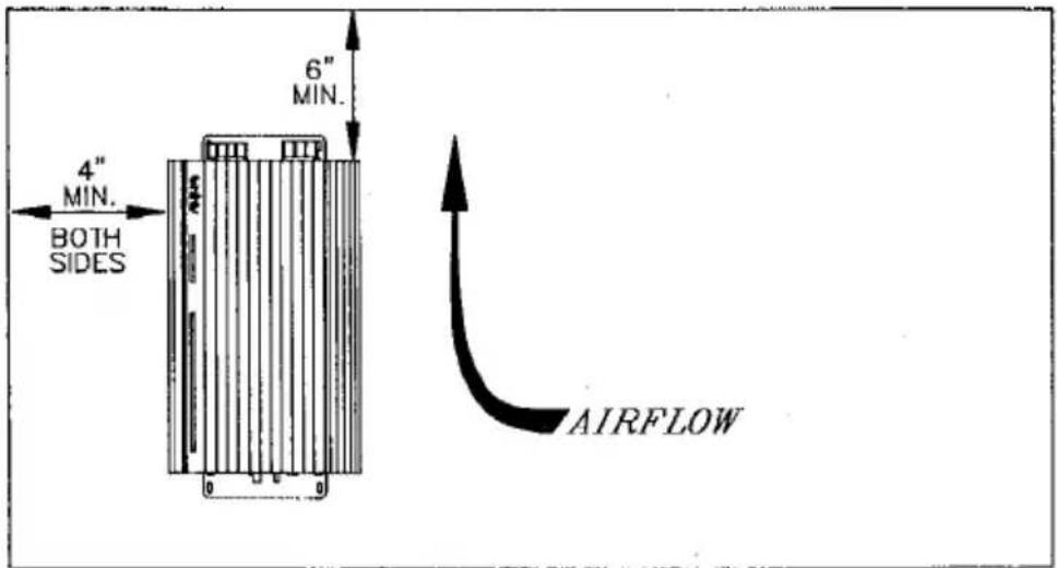
text_image
6" MIN. 4" MIN. BOTH SIDES AIRFLOWIf necessary, the amplifier may be mounted horizontally (on the floor of the vehicle's trunk, for example). (See figure 2.)
Figure 2:

text_image
4" MIN. 6" MIN. AIRFLOW 6" MIN. 4" MIN. 4" SIDES BOTH SIDES BOTH SIDESThe amplifier may also be mounted vertically (against the back of the rear seat), but with its heat sink fins running horizontally. (See figure 3.)
Figure 3:

text_image
4" MIN. 6" MIN. BOTH SIDES AIRFLOWNEVER mount the amplifier upside down or at an oblique angle since air cannot properly circulate above the amplifier for adequate heat dissipation.
Whenever possible, choose a mounting location that allows access to the amplifier's wiring connectors and controls, to facilitate setting the input sensitivity level, as well as accommodating any possible future configuration changes.
After determining the best location for the amplifier, and ONLY after making sure that its installation will not pose a threat to any of the vehicle's wiring or fuel lines/tank, set the amplifier in place and mark the location of its mounting holes with a marking pen. Remove the amplifier and drill the four mounting holes using a 1/8" drill bit.
NOTE: If the mounting surface is covered with carpeting or upholstery, use a sharp knife to cut a small "x" in the material at each screw hole location before drilling the holes. This will prevent stretching or tearing the material and will help keep carpet fibers from entangling in the drill. Mount the amplifier using the screws provided. Drive the screws through the mounting holes in the amplifier's bottom plate into the mounting surface. (See figure 4.)
Figure 4:
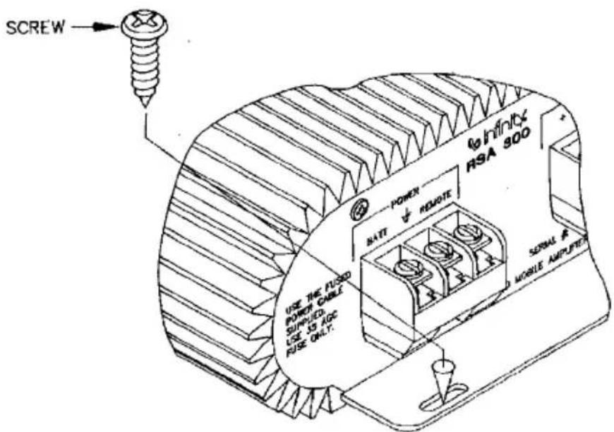
text_image
SCREW Power MATT √ RELOTEINFINITE
RSA 300 USE THE FLUO POWER CABLE SUPPLIED USE 15 ADC FUSE ONLY. SERIAL # MOBILE AMPUTERTighten the screws evenly until the amplifier is secure. Avoid stripping the screws by overtightening.
WIRING:
Proper wiring, along with the proper types of wires used, is important for optimum performance and reliability. Use only high quality, shielded cables for the low-level input signal connections. For speaker connections, use twin lead, stranded cable of at least 18 gauge. (Use of heavier gauge cable, or cables that are specially constructed for higher quality, may improve the overall quality of the sound of your system; consult your dealer.) Be sure that the speaker cables are polarity coded; that is, one of the conductors is marked in a special way so that it can be traced. A ridge or stripe is common, or the conductor itself may be a different color than its complimentary conductor (copper and silver colored, for example). In some cases the conductor is labeled with "+" and "-" Polarity marking is a must to insure connecting the speakers in proper phase. All cables are to be run inside the vehicle. Exposing the cables to
the exterior elements will cause rapid deterioration of their insulation. Avoid running cables against sharp edges, avoid instances where the cables will be subject to stress and strain, and avoid exposing the cables to excessive heat or vibration. The generous use of strain reliefs, rubber grommets, plastic tubing and tape will help keep the cables well protected at all times.
To keep noise levels as low as possible avoid running the power supply cables alongside the audio signal cables. Also avoid running the audio signal cables near the vehicle's existing wiring harnesses and accessories such as ignition control modules, fan motors and the like.
All connections should be soldered for long-term reliability, and insulated with tape or heat shrinkable tubing. Never leave connections exposed or dangling free in areas where they may get snagged or pulled.
The RSA amplifiers employ gold-plated screw terminals to insure ease of connection as well as optimum coupling and long term reliability. Connection is made by simply loosening the screw several turns, inserting the stripped end of the wire under the terminal plate and tightening the screw firmly. (See figure 5.) If desired, you may terminate the end of each cable with a number 10 spade lug or ring terminal. To attach a ring terminal, remove the screw completely, position the ring terminal over the screw and reinsert it, tightening it firmly.
Figure 5:
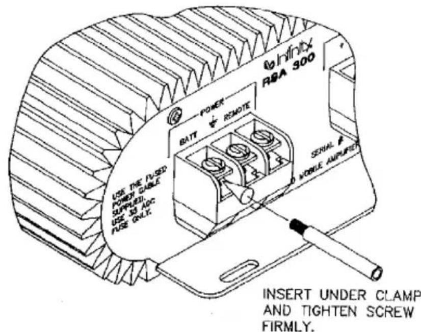
text_image
INFLIX RBA 300 POWER BATT REMOTE USE THE FUSED FOMOT CABLE SUPPLIED USE 33 ADC FUSE ONLY. SERIAL MOBILE AMPUFTER INSERT UNDER CLAMP AND TIGHTEN SCREW FIRMLY.CONNECTING THE AMPLIFIER, STEREO MODE: (RSA 120, 250 and 450)
Refer to figure 6. Set the mode switch of the amplifier to its "stereo" (in) position. Using the shortest length of shielded cable possible, connect the preamp outputs of your front-end unit the input jacks on the amplifier. Be sure to connect the left channel output to the left input jack, and the right to the right. Insure solid, firm connections which will not work loose in time.
Figure 6:
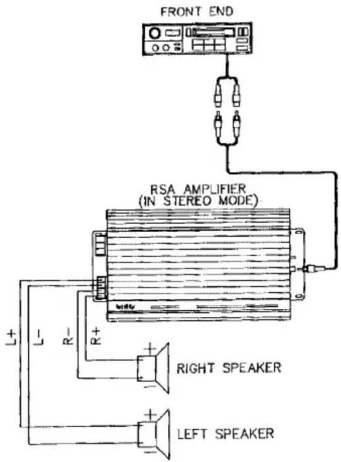
text_image
FRONT END RSA AMPLIFIER (IN STEREO MODE) L+ L- R- R+ RIGHT SPEAKER LEFT SPEAKERIf you are using a preamp device, connect the outputs of the front-end unit to the inputs of the preamp, then the outputs of the preamp to the inputs of the amplifier as per above.
Connect the speaker outputs to the car speakers, left channel to left speaker, right to right, being careful to observe proper polarity at all times. The “+” terminals of the amplifier must connect to the corresponding “+” or positive terminals of your speakers. This terminal may be marked with a “+”, a red dot or stripe, and may be about twice as large as the negative or “-” terminal in most cases. (If the terminals are not coded, connect the “+” terminal of a 9 volt transistor battery to one terminal. Touch the “-” terminal of the battery to the other speaker terminal for an instant while watching the speaker cone. If the cone moves out [away from the magnet, towards the grille] then the speaker terminal that the “+” of the battery is connected to is the “+” or positive terminal. If the cone moves in, then that terminal is the “-” or negative terminal. Mark the “+” terminal with a red felt pen or similar to insure proper phasing.)
CONNECTING THE AMPLIFIER, MONO MODE: (RSA 120, 250 and 450)
When the mode switch of the amplifier is set to "bridged" (its out position), the input jacks become a pair of summing inputs which combine both of their signals to create one mono signal to be amplified. This allows for using one amplifier to power the right speakers and another for the left, as well as allowing the use of a mono subwoofer system with an electronic crossover network.
When using one amplifier for each channel, refer to figure 7: using the shortest length of shielded cable possible, connect the left channel preamp output of your front-end unit to either input jack on the amplifier which will power the left speakers. Likewise, connect the right channel preamp output of the front-end unit to either input jack on the amplifier which will power the right speakers. Insure solid, firm connections which will not work loose in time.
Figure 7:

text_image
re 7: FRONT END RSA AMPLIFIER (IN BRIDGED MODE) LEFT SPEAKER (MIN. LOAD 4 OHMS) BRIDGE - (L -) BRIDGE + (R +) TO EITHER JACK RIGHT RSA AMPLIFIER (IN BRIDGED MODE) RIGHT SPEAKER (MIN. LOAD 4 OHMS) BRIDGE - (L -) BRIDGE + (R +) TO EITHER JACKConnect the speakers to the amplifiers at their "bridge +" and "bridge -" terminals.
When using one bridged amplifier to power a subwoofer system, refer to figure 8: using the shortest length of shielded cable possible, connect the preamp outputs of your front-end unit to the input jacks of the subwoofer's electronic crossover network. Then connect the subwoofer output signal jack (usually labeled "low-pass" or "woofer out" — see the system's owners manual) to either input jack of the amplifier which will power the subwoofer. If the crossover has a pair of woofer output jacks, connect them both to both input jacks of the amplifier which will power the subwoofer. The amplifier will sum the signals for a mono output to the subwoofer. Set the mode switch of the amplifier to "bridged" (out) and connect the subwoofer's speaker terminals to the amplifier at its "bridge +" and "bridge -" terminals.
Figure 8:
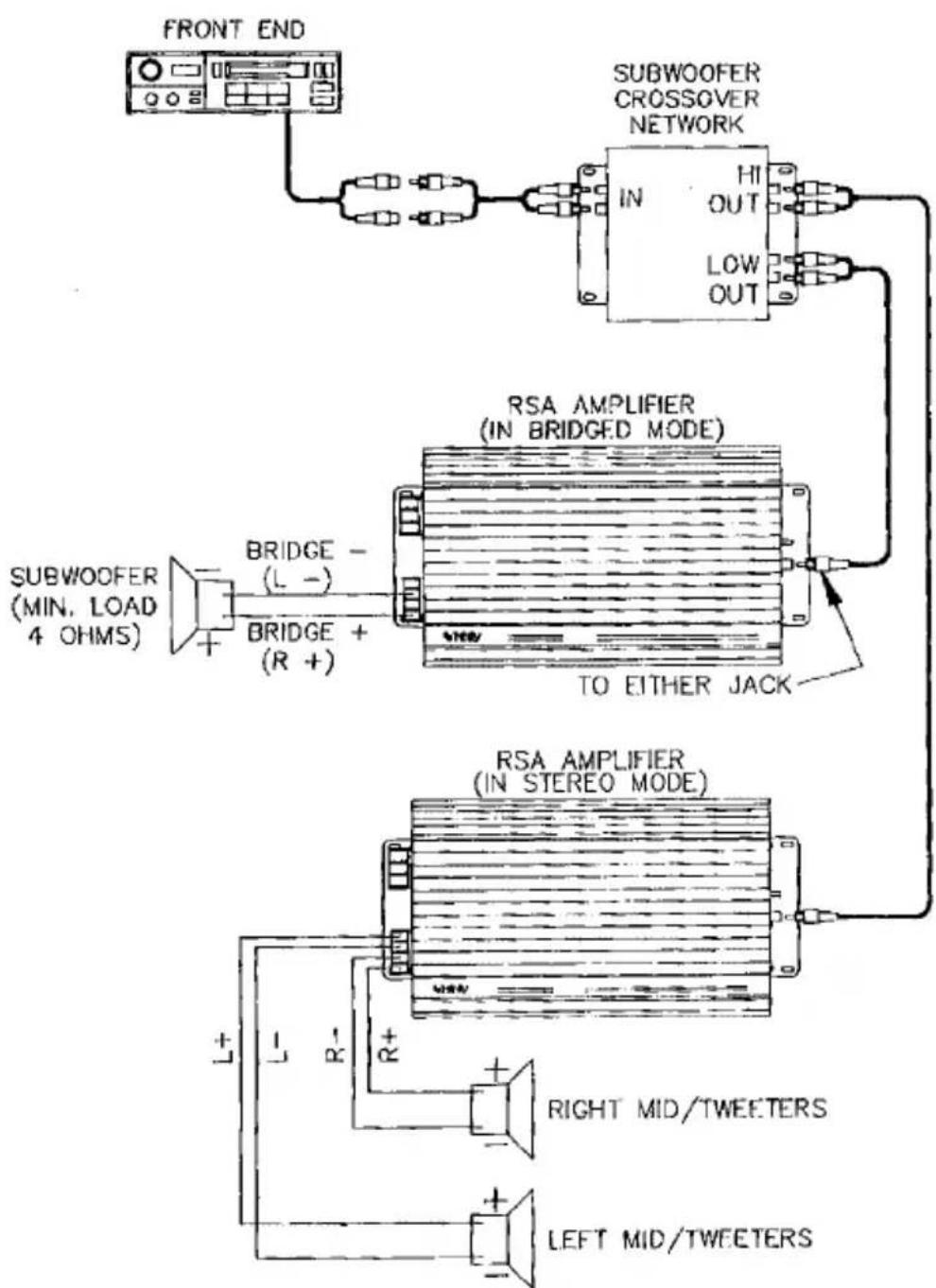
text_image
FRONT END SUBWOOFER CROSSOVER NETWORK IN HI OUT LOW OUT RSA AMPLIFIER (IN BRIDGED MODE) TO EITHER JACK SUBWOOFER (MIN. LOAD 4 OHMS) BRIDGE - (L -) BRIDGE + (R +) RSA AMPLIFIER (IN STEREO MODE) L R- R+ RIGHT MID/TWEETERS LEFT MID/TWEETERSCONNECTING THE AMPLIFIER:
4-CHANNEL MODE, 4x40 WATTS (RSA 4·40 only)
The RSA 4•40 can be used to drive two pairs of speakers, such as front and rear speakers if your front-end unit is so equipped. Refer to figure 9. Set both mode switches to their “stereo” (in) position. Connect the “front” pair of preamp outputs from your front-end unit to the “front” pair of input jacks on the amplifier. Connect the “rear” pair of outputs to the “rear” pair of inputs. Be sure to connect the left channel outputs to the left input jacks, and the right to the right. Insure solid, firm connections which will not work loose in time.
Figure 9:

text_image
FRONT END FRONT REAR RSA 4·40 (BOTH MODES AT "STEREO") RF- RF+ RR+ RR+ LR+ LR- RIGHT REAR SPEAKER LEFT REAR SPEAKER RIGHT FRONT SPEAKER LEFT FRONT SPEAKER LF+ RF-Connect the amplifier's "front" speaker outputs to your vehicle's front speakers, and the "rear" speaker outputs to your vehicle's rear speakers. Be sure to connect the left channel outputs to the left speakers, and right to right, observing proper polarity at all connections.
CONNECTING THE AMPLIFIER: 2-CHANNEL MODE, 2x80 WATTS (RSA 4•40 only)
Refer to figure 10. Set both of the mode switches to their "bridged" (out) position. Connect the left channel preamp output of your front-end unit to either of the amplifier's "front" input jacks. Connect the front-end unit's right channel preamp output to either of the amplifier's "rear" input jacks.
Figure 10:

text_image
FRONT END RSA 4·40 (BOTH MODES AT "BRIDGED") FRONT REAR TO EITHER JACK (BOTH SECTIONS) FRONT REAR BRIDGE - (L -) BRIDGE + (R +) BRIDGE - (L -) LEFT SPEAKERS (MIN. LOAD 4 OHMS) RIGHT SPEAKERS (MIN. LOAD 4 OHMS)Connect the left speaker cables to the "bridge +" and "bridge -" terminals of the amplifier's "front" speaker terminal strip. Connect the right speaker cables to the "bridge +" and "bridge -" terminals of the amp's "rear" terminal strip. Observe proper polarity.
CONNECTING THE AMPLIFIER:
3-CHANNEL MODE, 1x80 WATTS & 2x40 WATTS (RSA 4·40 only)
Refer to figure 11. This method of connection is very well suited to bi-amping a single subwoofer speaker system while only using one amplifier. A low-level crossover network will be necessary. Connect the outputs of your front-end unit to the inputs of the crossover. Set the mode switch of the "front" section of the amplifier to "stereo" (in) and connect the "high-pass" outputs of the crossover to the inputs of the amplifier's "front" section. Be sure to observe proper left-to-left and right-to-right connections. Set the mode switch of the amplifier's "rear" section to "bridged" (out) and connect the crossover's "low-pass" outputs to the rear "input" jacks of the amplifier. (The rear section of the amplifier will "sum" the low-pass outputs, creating one mono signal for the subwoofer.)
Figure 11:
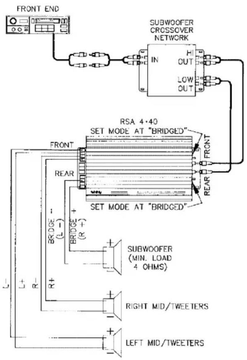
text_image
FRONT END SUBWOOFER CROSSOVER NETWORK IN OUT LOW OUT RSA 4·40 SET MODE AT "BRIDGED" FRONT REAR SET MODE AT "BRIDGED" FRONT L+ R- BRIDGE + (L -) BRIDGE + (R +) SUBWOOFER (MIN. LOAD 4 OHMS) RIGHT MID/TWEETERS LEFT MID/TWEETERSConnect the amplifier's "front" speaker outputs to your vehicle's midranges/tweeters. Observe proper polarity and left-to-left, right-to-right connection.
Connect the amplifier's "rear" speaker "bridge +" and "bridge -" outputs to the subwoofer. Observe proper polarity.
It may also be possible to have a mono (single) low-pass output coming from your low-level crossover unit. Connect this signal cable to either "rear" input jack and set the amplifier's "rear" mode switch to "bridged" (out). If using one subwoofer, connect it to the amp's "rear" speaker "bridge +" and "bridge -" terminals. If there are two subwoofers, connect them to the "rear" terminals per normal.
POWER CONNECTIONS:
Each Infinity Reference Standard Amplifier is supplied with a fused power cable and a ground cable. You will have to supply the cable to connect to the remote terminal of the amplifier. An 18 gauge cable is sufficient for this connection.
It is necessary to bypass all of the vehicle's wiring and connect the amplifier's power cable directly to the battery itself. The current required by the amplifier would most likely overload the vehicle's fuses. Figure 12 illustrates the power connections.
Figure 12:

text_image
FRONT END REMOTE POWER LEAD* (POWER ANTENNA) BATTERY FUSE RSA AMPLIFIER* IF YOUR FRONT-END UNIT DOES NOT HAVE A REMOTE POWER OR POWER ANTEMNA LEAD, CONNECT THE AMPLIFIER'S "REMOTE" TERMINAL TO A TERMINAL ON YOUR VEHICLE'S FUSE BOX WHICH IS FOR THE HEATER, RADIO, OR OTHER ACCESORY WHICH HAS POWER ONLY WHEN THE IGNITION IS TURNED ON.
When installing the RSA 450 you will notice that two very heavy fused cables are provided for the battery power connection. It is necessary to use both cables together, side-by-side from the amplifier to the battery in order to safely handle all of the current which the amplifier may require. (For simplicity's sake this pair of cables will be considered as one cable throughout the rest of this manual.) Connect the end of the battery power cable which is furthest away from its fuse to the "BATT" terminal of the amplifier FIRST. DO NOT connect the cable to the battery first since the cable would then carry live battery voltage which could cause a short circuit if the end of the live cable touched the wrong places.
Connect the end of the battery power cable nearest its fuse securely to the battery's "+" terminal. Coat this connection with grease or a commercial corrosion preventative.
Connect the stripped end of the heavy black cable to the “-” terminal of the amplifier. Connect the end of the cable with the ring terminal securely to a clean, bare section of the car's metal framework. Use a large sheet metal screw and a lockwasher for this, and only tighten the screw until it is secure: do not strip the screw by overtightening it. Coat this connection with a corrosion preventative.
Connect the amplifier's "REMOTE" terminal to the remote power lead (power antenna) of your front-end unit if it has one. If your front-end does not provide a switched source of +12 volts, connect the remote terminal to a terminal on your fusebox which is active only when the vehicle's key is in the "on" or "accessory" position. Do not connect this terminal directly to the battery or to any "always on" fuse (such as the headlight fuse) since the amplifier would always be on, and would gradually drain your vehicle's battery.
Visually inspect the system's wiring before turning the system on. Check that the fuses are securely installed in their holders, that all connections are secure and properly insulated, and that the ground lug is firmly anchored into the car's metal framework. Verify that all audio signal cables are properly phased (left to left, right to right) and securely fastened. Reconnect the negative battery cable to the battery and start the car's engine.
Be sure that the amplifier's mode selector is set to the proper position: in for stereo operation, out for bridged (mono).
Rotate the sensitivity control fully counterclockwise, then bring it up (clockwise) about 1/4 turn. Begin with the front-end unit's volume at minimum and turn it on. The red LED on the amplifier should begin to glow. Insert a high-quality full-range music tape (or compact disk if so equipped), or tune the stereo into a strong FM station and slowly turn up the volume to a moderate level. Turn the front-end unit's balance control to the left and right and verify output in the corresponding speakers at each extreme. Return the balance to the center position.
SETTING THE INPUT SENSITIVITY CONTROL:
It generally requires two people to perform this adjustment. To insure optimum performance with the lowest system noise level, proper setting of this control is very important.
Set the tone controls of the front-end unit to their normal operating positions and turn the volume up to the two or three o'clock position. The music source must be ultraclean with excellent dynamic range for this adjustment. Adjust the sensitivity control until the first signs of distortion are detected, then back the control off a bit. This is the correct setting of the control.
When using more than one amplifier in a bi-amped or tri-amped system, the sensitivity controls can also be used to balance the overall sound. This adjustment can be complex and may require lengthy trial and error. It is recommended that you consult your Infinity automotive dealer for assistance with this type of adjustment.
TROUBLESHOOTING GUIDE:
★ No Power
- Check connections to the vehicle's battery.
- Check ground connection.
- Check power cable fuse(s).
★ Amplifier Turns On and Off
- Check for loose ground or battery cable.
2 Check battery voltage. If it is below 10.5 volts the amplifier will not come on. - Check alternator output.
★ Power Without Sound
- Check all input and output signal cables.
★ Amplifier Will Not Turn On
- Check battery voltage (must be above 10.5 volts.
- Verify voltage on remote turn-on lead.
TO INSURE CONTINUED ENJOYMENT FROM YOUR RSA AMPLIFIER:
For long-term reliability and performance the heatsink fins must be kept clean and free of dust, grease and other foreign matter. Do not drape wires across the heatsink fins, and do not allow anything to lie up against the amplifier. Restricted airflow will reduce the amplifier's performance level and may shorten its life if not corrected. Periodically check the battery and ground connections to make sure they are not working loose or becoming corroded. Also check the mounting screws to see that the amplifier does not work itself loose, especially if subject to excessive or severe vibrations.
Infinity strives always to improve existing products as well as create new ones. Therefore the specifications and construction details in this publication are subject to change without notice.
ONE (1) YEAR LIMITED WARRANTY AUTOMOTIVE PRODUCTS
The Infinity warranty on automotive loudspeaker, crossover and amplifier products remains in effect for one year from the original date of purchase and is not transferable.
What is covered?
Except as covered below, the warranty covers all defects in original materials and workmanship. The following are not covered: damage caused by accident, misuse, abuse, neglect, product modification, damage occurring during shipment; damage caused by failure to follow instructions in either the owner's manual or on the carton, including failure to perform recommended periodic or routine maintenance; damage resulting from repairs by someone not authorized by Infinity; claims based upon any misrepresentation by the seller; any Infinity product on which the serial number has been altered, defaced or removed.
Who pays for what?
During the period that both parts and labor are covered by this warranty Infinity will pay all the labor and material expenses to repair a warrantable defect; during the period that parts ONLY are covered by this warranty, Infinity will pay for all materials to correct a warrantable defect, but you must pay for the labor charges.
How can warranty service be obtained?
In the event that your Infinity automotive product requires service, you should first contact the authorized Infinity dealer from whom you purchased the product or, if this is not practical, contact Infinity (ATTN: Customer Service), 9409 Owensmouth Ave., Chatsworth, CA 91311, (818) 709-9400. We may direct you to an authorized service center for Infinity products or ask you to send your unit(s) to us for repair. In either case you will have to present your original dated bill-of-sale to establish warranty coverage. Do not send your product to us without prior authorization from our Customer Service department.
You are responsible for transporting your product to either Infinity or an authorized service center and for payment of all shipping charges; however, Infinity will pay the return shipping charges (in the event you return the product to us) if the repairs are covered by the warranty. If you experience difficulty in transporting your product or are in need of packing materials, please advice us and we may be able to suggest alternative procedures and/or provide adequate packaging materials.
LIMITATION OF IMPLIED WARRANTIES: All implied warranties, including fitness for a particular purpose and merchantability are limited in duration to the length of the warranty period for your product.
LIMITATION OF INCIDENTAL OR CONSEQUENTIAL DAMAGES: Inifinty is not responsible for any incidental or consequential damage of any kind. Our liability is limited to the repair or replacement, at our option, of a defective product.
Some states do not allow limitations on how long an implied warranty lasts and/or do not allow the exclusion of incidental or consequential damage, so the above limitations or exclusions may not apply to you.
This warranty gives you specific legal rights and you may also have other rights which vary from state to state.
NOTE: In the event that there is difference between this warranty and the provisions in any advertisements, product brochures or packaging cartons, the terms of this warranty will prevail.