
ADAM-6160EI-AE - Programmable Logic Controller Advantech - Free user manual and instructions
Find the device manual for free ADAM-6160EI-AE Advantech in PDF.


| Product Type | EtherNet/IP Remote I/O Relay Module |
| Number of Channels | 6 relay channels (5 Form C, 1 Form A/B selectable) |
| Contact Rating (AC) | 250 V @ 5 A |
| Contact Rating (DC) | 30 V @ 5 A |
| Breakdown Voltage | 500 VAC (50/60 Hz) |
| Relay On/Off Time | 7 ms on / 3 ms off |
| Contact Resistance | 30 mΩ (max.) |
| Insulation Resistance | 1 GΩ at 500 V DC |
| Communication Interface | 10/100 Base-T Ethernet (2 ports for daisy chain) |
| Supported Protocol | EtherNet/IP |
| Isolation Protection | 2,500 VDC triple isolation (power, I/O, Ethernet) |
| Power Input | Unregulated 10 ~ 30 V DC |
| Power Consumption | 3.5 W @ 24 V DC |
| Operating Temperature | -10 ~ 70 °C |
| Storage Temperature | -20 ~ 80 °C |
| Operating Humidity | 20 ~ 95% RH (non-condensing) |
| Dimensions (approx.) | 120 x 100 x 30 mm |
| Weight (approx.) | 200 g |
| Safety Functions | Power reversal protection; FSV safety function |
| LED Indicators | Status/COM, Link/Speed 1, Link/Speed 2 |
| Configuration | DIP switch for Initial/Normal mode; ADAM.Net utility |
| Cleaning Instructions | Disconnect power; use a damp cloth; no liquid detergents |
| Spare Parts / Repairability | No user-serviceable parts; contact authorized service for repairs |
| Warranty | 2 years from date of purchase |
Frequently Asked Questions - ADAM-6160EI-AE Advantech
User questions about ADAM-6160EI-AE Advantech
0 question about this device. Answer the ones you know or ask your own.
Ask a new question about this device
Download the instructions for your Programmable Logic Controller in PDF format for free! Find your manual ADAM-6160EI-AE - Advantech and take your electronic device back in hand. On this page are published all the documents necessary for the use of your device. ADAM-6160EI-AE by Advantech.
USER MANUAL ADAM-6160EI-AE Advantech
natural_image
Line drawing of industrial electronic equipment units arranged in a row (no text or symbols)ADAM-6100EI Series
EtherNet/IP I/O Modules
Copyright
The documentation and the software included with this product are copyrighted 2009 by Advantech Co., Ltd. All rights are reserved. Advantech Co., Ltd. reserves the right to make improvements in the products described in this manual at any time without notice. No part of this manual may be reproduced, copied, translated or transmitted in any form or by any means without the prior written permission of Advantech Co., Ltd. Information provided in this manual is intended to be accurate and reliable. However, Advantech Co., Ltd. assumes no responsibility for its use, nor for any infringements of the rights of third parties, which may result from its use.
Acknowledgements
Intel and Pentium are trademarks of Intel Corporation.
Microsoft Windows and MS-DOS are registered trademarks of Microsoft Corp.
All other product names or trademarks are properties of their respective owners.
Product Warranty (2 years)
Advantech warrants to you, the original purchaser, that each of its products will be free from defects in materials and workmanship for two years from the date of purchase.
This warranty does not apply to any products which have been repaired or altered by persons other than repair personnel authorized by Advantech, or which have been subject to misuse, abuse, accident or improper installation. Advantech assumes no liability under the terms of this warranty as a consequence of such events.
Because of Advantech's high quality-control standards and rigorous testing, most of our customers never need to use our repair service. If an Advantech product is defective, it will be repaired or replaced at no charge during the warranty period. For out-of-warranty repairs, you will be billed according to the cost of replacement materials, service time and freight. Please consult your dealer for more details.
If you think you have a defective product, follow these steps:
-
Collect all the information about the problem encountered. (For example, CPU speed, Advantech products used, other hardware and software used, etc.) Note anything abnormal and list any onscreen messages you get when the problem occurs.
-
Call your dealer and describe the problem. Please have your manual, product, and any helpful information readily available.
-
If your product is diagnosed as defective, obtain an RMA (return merchandise authorization) number from your dealer. This allows us to process your return more quickly.
-
Carefully pack the defective product, a fully-completed Repair and Replacement Order Card and a photocopy proof of purchase date (such as your sales receipt) in a shippable container. A product returned without proof of the purchase date is not eligible for warranty service.
-
Write the RMA number visibly on the outside of the package and ship it prepaid to your dealer.
Part No. 2003610000 Edition 1
Printed in Taiwan April 2012
Declaration of Conformity
CE
This product has passed the CE test for environmental specifications when shielded cables are used for external wiring. We recommend the use of shielded cables. This kind of cable is available from Advantech. Please contact your local supplier for ordering information.
FCC Class A
Note: This equipment has been tested and found to comply with the limits for a Class A digital device, pursuant to part 15 of the FCC Rules. These limits are designed to provide reasonable protection against harmful interference when the equipment is operated in a commercial environment. This equipment generates, uses, and can radiate radio frequency energy and, if not installed and used in accordance with the instruction manual, may cause harmful interference to radio communications. Operation of this equipment in a residential area is likely to cause harmful interference in which case the user will be required to correct the interference at his own expense.
Technical Support and Assistance
- Visit the Advantech web site at www.advantech.com/support where you can find the latest information about the product.
- Contact your distributor, sales representative, or Advantech's customer service center for technical support if you need additional assistance. Please have the following information ready before you call:
– Product name and serial number
– Description of your peripheral attachments
– Description of your software (OS, version, application software, etc.)
– A complete description of the problem - The exact wording of any error messages
Safety Precaution - Static Electricity
Follow these simple precautions to protect yourself from harm and the products from damage.
To avoid electrical shock, always disconnect the power from your PC chassis before you work on it. Don't touch any components on the CPU card or other cards while the PC is on.
Disconnect power before making any configuration changes. The sudden rush of power as you connect a jumper or install a card may damage sensitive electronic components.
Safety Instructions
- Read these safety instructions carefully.
- Keep this User Manual for later reference.
- Disconnect this equipment from any AC outlet before cleaning. Use a damp cloth. Do not use liquid or spray detergents for cleaning.
- For plug-in equipment, the power outlet socket must be located near the equipment and must be easily accessible.
- Keep this equipment away from humidity.
- Put this equipment on a reliable surface during installation. Dropping it or letting it fall may cause damage.
- The openings on the enclosure are for air convection. Protect the equipment from overheating. DO NOT COVER THE OPENINGS.
- Make sure the voltage of the power source is correct before connecting the equipment to the power outlet.
- Position the power cord so that people cannot step on it. Do not place anything over the power cord.
- All cautions and warnings on the equipment should be noted.
- If the equipment is not used for a long time, disconnect it from the power source to avoid damage by transient overvoltage.
- Never pour any liquid into an opening. This may cause fire or electrical shock.
- Never open the equipment. For safety reasons, the equipment should be opened only by qualified service personnel.
- If one of the following situations arises, get the equipment checked by service personnel:
- The power cord or plug is damaged.
- Liquid has penetrated into the equipment.
- The equipment has been exposed to moisture.
- The equipment does not work well, or you cannot get it to work according to the user's manual.
- The equipment has been dropped and damaged.
- The equipment has obvious signs of breakage.
- DO NOT LEAVE THIS EQUIPMENT IN AN ENVIRONMENT WHERE THE STORAGE TEMPERATURE MAY GO BELOW -20°C (-4°F) OR ABOVE 60°C (140°F). THIS COULD DAMAGE THE EQUIPMENT. THE EQUIPMENT SHOULD BE IN A CONTROLLED ENVIRONMENT.
- CAUTION: DANGER OF EXPLOSION IF BATTERY IS INCORRECTLY REPLACED. REPLACE ONLY WITH THE SAME OR EQUIVALENT TYPE RECOMMENDED BY THE MANUFACTURER, DISCARD USED BATTERIES ACCORDING TO THE MANUFACTURER'S INSTRUCTIONS.
- The sound pressure level at the operator's position according to IEC 704-1:1982 is no more than 70 dB (A).
DISCLAIMER: This set of instructions is given according to IEC 704-1. Advantech disclaims all responsibility for the accuracy of any statements contained herein.
Chapter 1 Overview......1
1.1 Introduction ...... 2
1.2 System Architecture .... 2 Figure 1.1 ADAM-6100EI Daisy Chain Connections .... 2
1.3 Features .... 3
1.3.1 Daisy Chain Connection .... 3
1.3.2 2,500V Isolation Protection .... 4
1.3.3 Ethernet-based Configuration Tool 4
1.3.4 Status LED Indicator 5
Chapter 2 Product Specifications....7
2.1 Digital I/O Modules....8
2.1.1 Overview 8
Figure 2.1 ADAM-6150EI....8
Figure 2.2 ADAM-6151EI....8
Figure 2.3 ADAM-6156EI....9
2.1.2 Specifications....9
2.1.3 Switch Settings 10
2.1.4 Application Wiring 11
2.2 Relay Modules 13
2.2.1 Overview 13
Figure 2.4 ADAM-6160EI.... 13
2.2.2 Specifications.... 13
2.2.3 Jumper Settings 14
2.3 Analog I/O Modules.... 15
2.3.1 ADAM-6117EI: 8-ch Isolated Analog Input Module ..... 15
Figure 2.5 ADAM-6117EI.... 15
2.3.2 ADAM-6118EI: 7-ch Thermocouple and 1-ch CJC Input Module17
Figure 2.6 ADAM-6118EI.... 17
2.3.3 ADAM-6124EI: 4-ch Analog Output and 4-ch Digital Input Module 20
Figure 2.7 ADAM-6124EI.... 20
Chapter 1
Overview
1.1 Introduction
ADAM-6100EI is a series of EtherNet/IP remote I/O modules. EtherNet/IP protocol is very popular in industrial automation applications and all ADAM-6100EI series modules can comply with it. You can easily connect ADAM-6100EI modules to EtherNet/IP masters, like Allen-Bradley PLC, through EtherNet/IP protocol. ADAM-6100EI series module supports Initial mode and Normal mode (EtherNet/IP mode), that you can set by the DIP switch on the side of ADAM module. Refer to Section 1.3.3 for how to configure it. When you configure the mode as Initial mode, you can configure ADAM-6100EI module's IP address and related setting by Advantech APAX/ADAM.Net utility. When you configure the mode as Normal mode, ADAM-6100EI modules are ready to communicate with EtherNet/IP master by EtherNet/IP protocol.
1.2 System Architecture
ADAM-6100EI series modules can be daisy-chained in an Ethernet network, making it easier to deploy, and helping improve scalability. You can refer to the figure below to see how a daisy-chain connection works in the network.
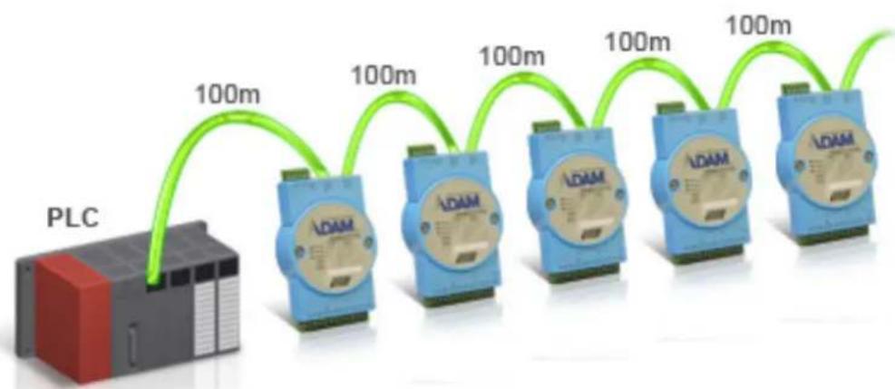
flowchart
graph LR
    A["PLC"] -->|100m| B["LDAM"]
    B -->|100m| C["LDAM"]
    C -->|100m| D["LDAM"]
    D -->|100m| E["LDAM"]
    E -->|100m| F["LDAM"]
Figure 1.1 ADAM-6100EI Daisy Chain Connections
1.3 Features
1.3.1 Daisy Chain Connection
ADAM-6100EI module has built in Ethernet switches to allow daisy chain connections in an Ethernet network, making it easier to deploy, and helping improve scalability. The two Ethernet ports are fully compliant with IEEE 802.3u 10/100Mbpst through standard RJ-45 connectors.
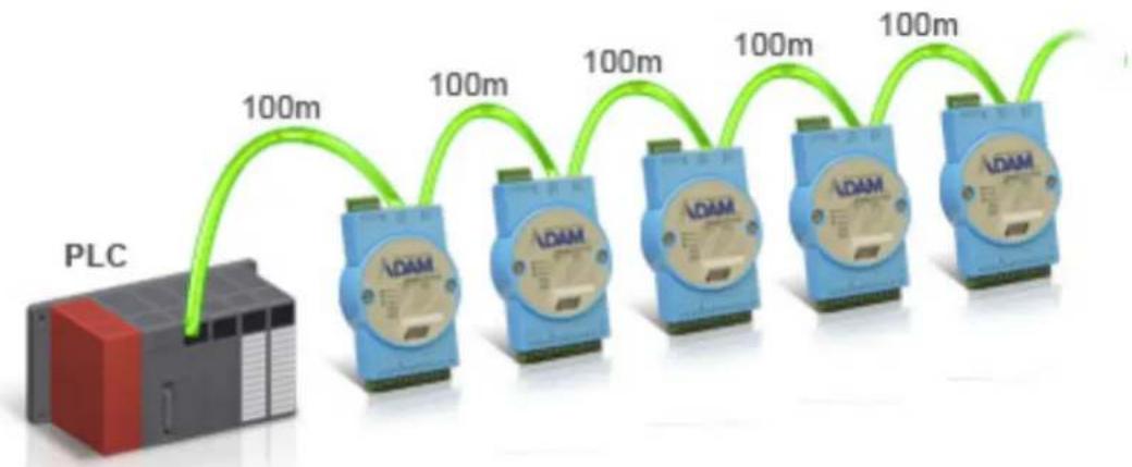
flowchart
graph LR
    A["PLC"] --> B["ADAM"]
    B --> C["LOAM"]
    C --> D["100m"]
    D --> E["100m"]
    E --> F["100m"]
    F --> G["100m"]
    G --> H["100m"]
    H --> I["100m"]
    I --> J["100m"]
    J --> K["100m"]
    K --> L["100m"]
    L --> M["100m"]
    M --> N["100m"]
    N --> O["100m"]
    O --> P["100m"]
    P --> Q["100m"]
    Q --> R["100m"]
    R --> S["100m"]
    S --> T["100m"]
    T --> U["100m"]
    U --> V["100m"]
    V --> W["100m"]
    W --> X["100m"]
    X --> Y["100m"]
    Y --> Z["100m"]
| Pin | Assignment | Description |
| 1 TD + | Transmit + | |
| 2 TD - | Transmit - | |
| 3 RD + | Receive + | |
| 4 N/C not used | ||
| 5 N/C not used | ||
| 6 RD - | Receive - | |
| 7 N/C not used | ||
| 8 N/C not used | ||
1.3.2 2,500V Isolation Protection
With triple isolation, including power supply, input/output, and Ethernet communication, ADAM-6100EI series ensures I/O data to be controlled correctly, and prevents devices from breaking down.

1.3.3 Ethernet-based Configuration Tool
You can configure ADAM-6100EI module as Initial mode or Normal mode by the DIP switch in the side of each module. When ADAM-6100EI module is set as Initial mode, you can use ADAM.Net utility to configure and test the module via Ethernet connection between PC and the module. This can ensure the ADAM-6100EI module is set properly and is working correctly before connecting it to an EtherNet/IP network. When ADAM-6100EI module is set as Normal mode, it can directly communicate with EtherNet/IP master device such as Allen-Bradley PLC by EtherNet/IP protocol.

flowchart
graph TD
    A["Ethernet"] --> B["LDAM"]
    B --> C["Laptop"]

1.3.4 Status LED Indicator
There are 3 LED indicators on the front of the ADAM-6100 module-Status/COM, Link/Speed 1, and Link/Speed 2. The Status/COM LED indicates the status of the module. The Link/Speed LEDs indicate the network connections of Ethernet port 1 and port 2. After power on, if the module is not connected to any network, the Status LED and the COM LED will keep ON. Once the module is connected, the Status LED and COM LED will work according to the table below.

| Status of the module* | ||
| Mode Status LED (Green) COM LED (Orange) | ||
| Init mode (Initial mode) ON/OFF flash ON during communication | ||
| Normal mode (EtherNet/IP mode) Keep ON ON during Communication | ||
| Module Error Keep OFF ON/OFF flash | ||
| Port Communication | ||
| Mode Link LED (Green) Speed LED (Orange) | ||
| Port 1 connected Link 1 will keep ON Speed 1 ON when network speed is 100M | ||
| Port 2 connected Link 2 will keep ON Speed 2 ON when network speed is 100M | ||
Chapter 2
Product Specifications
2.1 Digital I/O Modules
2.1.1 Overview
The ADAM-6150EI, ADAM-6151EI and ADAM-6156EI are a series of isolated digital I/O modules which support the EtherNet/IP protocol. According to the channel number difference, you can choose the best digital I/O modules for your application.
■ ADAM-6150EI: 8-ch isolated digital input and 7-ch isolated digital output module
■ ADAM-6151EI: 16-ch isolated digital input module
■ ADAM-6156EI: 16-ch isolated digital output module

Figure 2.1 ADAM-6150EI
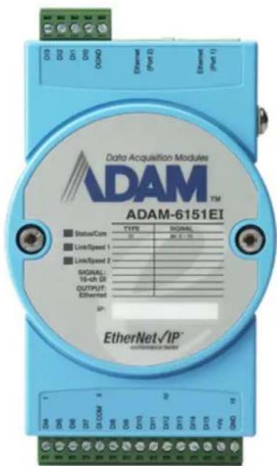
Figure 2.2 ADAM-6151EI
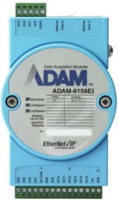
■ Normal Output Current: 100 mA (per channel)
■ FSV Safety Function
General
■ Communication: 10/100 Base-T Ethernet
■ Supported Protocol: EtherNet/IP
■ Power Input: Unregulated 10 \~ 30 V DC
■ Power Consumption: 2.4 W @ 24 V DC
■ Power Reversal Protection (30V Max.)
■ Operating Humidity: 20 \~ 95% RH (non-condensing)
■ Storage Humidity: 0 \~ 95% RH (non-condensing)
■ Operating Temperature: -10 \~ 70°C
■ Storage Temperature: -20 \~ 80°C
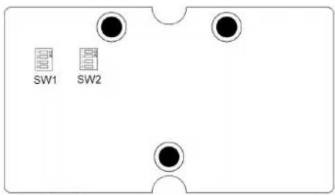
2.1.3 Switch Settings
ADAM-6150EI:
| Switch SW1 | SW2 | |||||||
| Position | 1 | 2 | 3 | 4 | 1 | 2 | 3 | 4 |
| DI Channel | Ch3 Ch2 Ch1 | Ch0 Ch7 | Ch6 Ch5 | Ch4 | ||||
| ON | Dry Contact (Default) | |||||||
| OFF | Wet contact | |||||||
ADAM-6151EI:

| Switch SW1 | SW2 | |||||||
| Position | 1 | 2 | 3 | 4 | 1 | 2 | 3 | 4 |
| DI Channel | C h | 3 | C h | 2 C h | 1 C h | 0 C h | ||
| Switch SW3 | SW4 | |||||||
| Position | 1 | 2 | 3 | 4 | 1 | 2 | 3 | 4 |
| DI Channel | Ch11 Ch | Ch10 Ch | 9 Ch8 Ch | Ch15 Ch | 14 Ch13 Ch | Ch12 | ||
| ON | Dry Contact (Default) | |||||||
| OFF | Wet contact | |||||||
h 7 C h 6 C
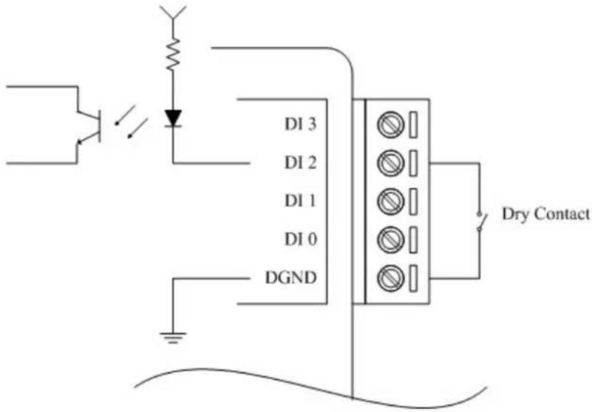
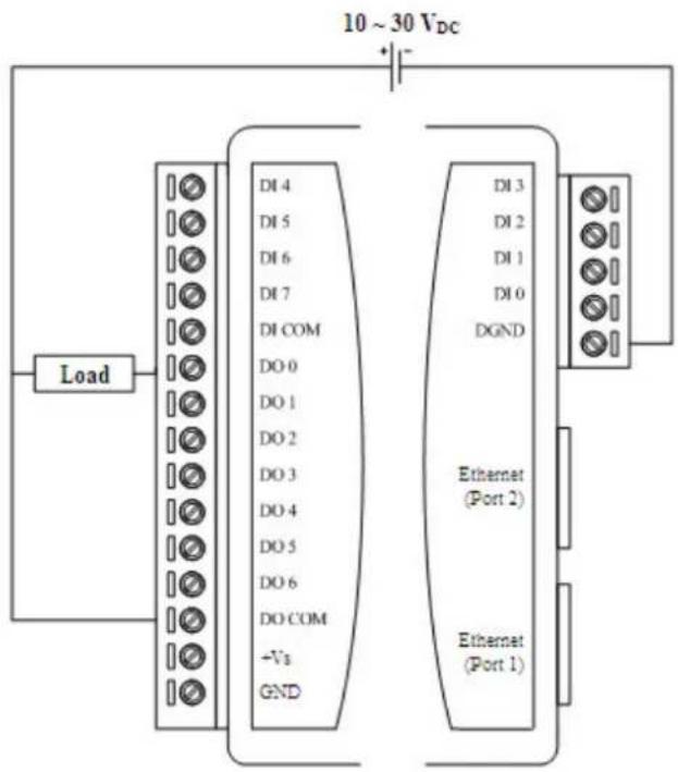
2.1.4 Application Wiring
Isolated Digital Input - Dry Contact
Isolated Digital Input - Wet Contact

Isolated Digital Output (ADAM-6150EI)
Isolated Digital Output (ADAM-6156EI)

2.2 Relay Modules
2.2.1 Overview
The ADAM-6160EI is a relay module which supports EtherNet/IP protocol. It provides 5 Form C and 1 Form A/B (selectable) relay channels and is excellent for ON/OFF control or low-power switching applications in an EtherNet/IP system.
■ ADAM-6160EI: 6-ch Relay Module

Figure 2.4 ADAM-6160EI
2.2.2 Specifications
Relay
■ Channels: 5 Form C and 1 Form A/B (selected by jumper)
- Contact Rating:
- AC: 250 V @ 5 A
- DC: 30 V @ 5 A
■ Breakdown Voltage: -500 VAC (50/60 Hz)
■ Mechanism: 20,000,000 operations
■ Relay on time: 7 ms
■ Relay off time: 3 ms
■ Contact Resistance: 30 mΩ (max.)
■ Insulation Resistance: 1 GΩ at 500 V _DC
■ FSV Safety Function
General
■ Communication: 10/100 Base-T Ethernet
■ Supported Protocol: EtherNet/IP
■ Power Input: Unregulated 10 \~ 30 V DC
■ Power Consumption: 3.5 W @ 24 V DC
■ Power Reversal Protection (30V Max.)
■ Operating Humidity: 20 \~ 95% RH (non-condensing)
■ Storage Humidity: 0 \~ 95% RH (non-condensing)
■ Operating Temperature: -10 \~ 70°C
■ Storage Temperature: -20 \~ 80°C
2.2.3 Jumper Settings

natural_image
Pure electrical circuit lines without any symbols| CN7 Relay Ch0 | Configuration |
 | Normally Open (Default) |
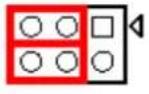 | Normally Closed |
Note!Users need to separate two PC boards to set the jumpers of the ADAM-6160EI.

2.3 Analog I/O Modules
2.3.1 ADAM-6117EI: 8-ch Isolated Analog Input Module
2.3.1.1 Overview
The ADAM-6117EI is a 16-bit, 8-channel isolated analog input module. It accepts millivoltage inputs (±150 mV, ±500 mV), voltage inputs (±1 V, ±5 V and ±10 V) and current input (±20 mA, 0\~20 mA, 4\~20 mA). Each analog channel can be configured to an individual range for a variety of applications.

Figure 2.5 ADAM-6117EI
2.3.1.2 Specifications
Analog Input:
• Channels: 8 (Differential)
- Input Impedance:
Voltage: >10 MΩ
Current: 120 Ω
- Input Type: V, mV, mA
- Input Range: ±150 mV, ±500 mV, ±1V, ±5V, ±10V, ±20 mA, 0\~20 mA, 4\~20 mA (different range can be configured for each channel in the utility)
- Accuracy:
Voltage: ±0.1% or better at 25°C
Current: ±0.2% or better at 25°C
- Resolution:
| Voltage Current | |
| Range Resolution Range Resolution | |
| ±150 mV 16 bit ±20mA 15 bit | |
| ±500 mV 16 bit 0~20 mA 14 bit | |
| ±1 V 16 bit 4~20 mA 14 bit | |
| ±5 V 16 bit | |
| ±10 V 16 bit | |
• Sampling Rate: 12 samples/second (total)
• CMR @ 50/60 Hz: 92 dB
• NMR @ 50/60 Hz: 60 dB
- Span Drift: ±30 ppm/°C
• Zero Drift: ±6 μV/°C
• Isolation Voltage: 2,500 V DC
• High Common Mode: up to 200 V DC
General:
- Communication: 10/100 Base-T Ethernet
• Supported Protocol: EtherNet/IP
• Power Input: Unregulated 10 \~ 30 V DC
• Power Consumption: 3 W max. @ 24 V DC
• Power Reversal Protection (30V max.) - Operating Humidity: 20 95% RH (non-condensing)
• Storage Humidity: 0 \~ 95% RH (non-condensing) - Operating Temperature: -10 \~ 70°C
- Storage Temperature: -20 \~ 80°C
2.3.1.3 Switch Settings
SW1\~SW4: Set input mode of each AI channel

| Switch SW1 | SW2 SW3 SW4 | |||||||
| Position | 1 | 2 | 1 | 2 | 1 | 2 | 1 | 2 |
| Channel | Ch1 Ch0 Ch3 | Ch2 Ch5 | Ch4 Ch7 | Ch6 | ||||
| ON | Current Mode | |||||||
| OFF | Voltage Mode (Default) | |||||||
2.3.1.4 Application Wiring

2.3.2 ADAM-6118EI: 7-ch Thermocouple Input Module
2.3.2.1 Overview
The ADAM-6118EI is a 16-bit, 7-channel thermocouple input module that provides programmable input ranges on all channels. It accepts various thermocouple inputs (Types J, K, T, E, R, S, B). It is designed for temperature measurement of several industrial control applications.

Figure 2.6 ADAM-6118EI
2.3.2.2 Specifications
Analog Input:
• Channels: 7 (Differential)
- Input Impedance:
Voltage: >10 MΩ
Current: 120
- Input Type: V, mV, mA, thermocouple
• Temperature Range: Type: J (-210 \~ 1,200°C), Type K (-270 \~ 1,372°C), Type T (-270 \~ 400°C), Type E (-270 \~ 1,000°C), Type R (0 \~ 1,768°C), Type S (0 \~ 1,768°C), Type B (200 \~ 1,820°C) - Voltage/Current Range: ±150 mV, ±500 mV, ±1 V, ±5 V, ±10 V, ±20 mA, 0\~20 mA, 4\~20 mA (different ranges can be configured for each channel in the utility)
- Accuracy:
Temperature: ±0.2% or better at 25°C
Voltage: ±0.1% or better at 25°C
Current: ±0.2% or better at 25°C
- Resolution:
| Temperature Voltage | Current | |
| Range Resolution Range | Resolution Range Resolution | |
| Type J 14 bit ±150 mV 16 | bit ±20 mA 15 bit | |
| Type K 14 bit ±500 mV 16 | bit 0~20 mA 14 bit | |
| Type T 14 bit ±1 V | 16 bit 4~20 mA 14 bit | |
| Type E 14 bit ±5 V | 16 bit | |
| Type R 14 bit ±10 V | 16 bit | |
| Type S 14 bit | 16 bit | |
| Type B 14 bit | 16 bit | |
• Sampling Rate: 12 samples/second (total)
• CMR @ 50/60 Hz: 92 dB
• NMR @ 50/60 Hz: 60 dB
- Span Drift: ±25 ppm/°C
• Zero Drift: ±6 μV/°C
• Isolation Voltage: 2,500 V DC
• High Common Mode: up to 200 V DC
General:
• Communication: 10/100 Base-T Ethernet
• Supported Protocol: Ethernet/IP
• Power Input: Unregulated 10 \~ 30 V DC
• Power Consumption: 3 W (max.) @ 24 V DC
• Power Reversal Protection (30V max.)
- Operating Humidity: 20 \~ 95% RH (non-condensing)
• Storage Humidity: 0 \~ 95% RH (non-condensing)
- Operating Temperature: -10 \~ 70°C
- Storage Temperature: -20 \~ 80°C
2.3.2.3 Switch Settings
SW1\~SW4: Set input mode of each AI channel

| Switch | SW1 | SW2 | SW3 | SW4 | ||||
| Position | 1 | 2 | 1 | 2 | 1 | 2 | 1 | 2 |
| Channel | Ch1 | Ch0 | Ch3 | Ch2 | Ch5 | Ch4 | Ch7 | Ch6 |
| ON | Current Mode | |||||||
| OFF | Voltage Mode/Thermocouple Mode (Default) | |||||||
2.3.2.4 Application Wiring
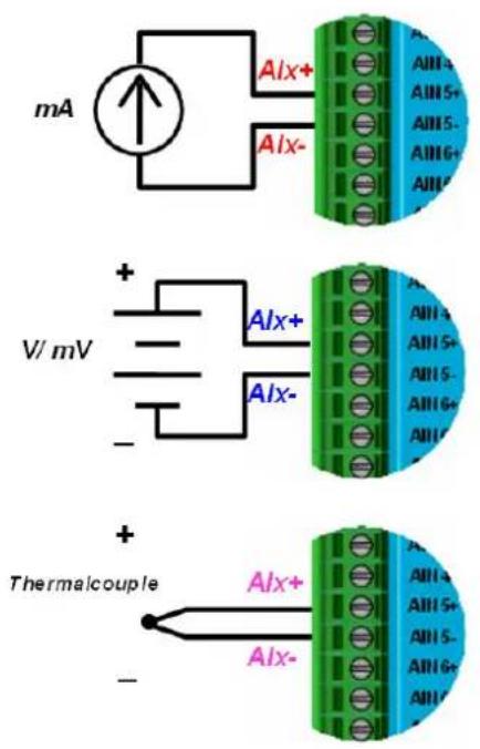
2.3.3 ADAM-6124EI: 4-ch Analog Output and 4-ch Digital Input Module
2.3.3.1 Overview
The ADAM-6124EI is a 12-bit, 4-channel analog output module along with 4-channel dry-contact digital input. It provides programmable output ranges on all channels and supports voltage and current outputs, which makes it an ideal output control solution.

Figure 2.7 ADAM-6124EI
2.3.3.2 Specifications
Analog Output:
- Channels: 4
- Output Type: V, mA
- Voltage/Current Range: 5V, 10V, ±5V, ±10V, 0\~20mA,4\~20 mA (different range can be configured for each channel in the utility)
- Resolution: 12-bit
• Output Impedance: 2.1Ω
• Output Settling Time: 20 us
• Output Slew Rate: 1.0 V/sec - Accuracy:
Voltage: ±0.1% or better at 25°C
Current: ±0.1% or better at 25°C
Digital Input:
- Channels: 4
- Input type: Dry Contact (Close to Iso.GND)
General:
• Communication: 10/100 Base-T Ethernet
• Supported Protocol: Ethernet/IP
• Power Input: Unregulated 10 \~ 30 V DC
• Power Consumption: 3 W (max.) @ 24 V DC
• Power Reversal Protection (30V max.)
- Operating Humidity: 20 \~ 95% RH (non-condensing)
• Storage Humidity: 0 \~ 95% RH (non-condensing)
- Operating Temperature: -10 \~ 70°C
- Storage Temperature: -20 \~ 80°C



- ADAM-6100EI Series
- Copyright
- Acknowledgements
- Product Warranty (2 years)
- Declaration of Conformity
- CE
- FCC Class A
- Technical Support and Assistance
- Safety Precaution - Static Electricity
- Safety Instructions
- Chapter 1 Overview......1
- Chapter 2 Product Specifications....7
- Chapter 1
- Introduction
- System Architecture
- Features
- Daisy Chain Connection
- 2,500V Isolation Protection
- Ethernet-based Configuration Tool
- Status LED Indicator
- Chapter 2
- Digital I/O Modules
- Overview
- General
- Switch Settings
- Application Wiring
- Relay Modules
- Overview
- Specifications
- Relay
- Jumper Settings
- Analog I/O Modules
- ADAM-6117EI: 8-ch Isolated Analog Input Module
- Overview
- Specifications
- Analog Input:
- General:
- Switch Settings
- Application Wiring
- ADAM-6118EI: 7-ch Thermocouple Input Module
- Overview
- Specifications
- Switch Settings
- Application Wiring
- ADAM-6124EI: 4-ch Analog Output and 4-ch Digital Input Module
- Overview
- Specifications
- Analog Output:
- Digital Input:
Brand : Advantech
Model : ADAM-6160EI-AE
Category : Programmable Logic Controller