
HEC2-S6.0Hr2 - Single-phase hybrid inverter V-TAC - Free user manual and instructions
Find the device manual for free HEC2-S6.0Hr2 V-TAC in PDF.


| Product Type | Hybrid Inverter Single Phase |
| Model | HEC2-S6.0Hr2 |
| Brand | V-TAC |
| Rated AC Output Power | 6000 W |
| Maximum AC Output Power | 6000 W |
| Nominal AC Voltage | 230 V (L/N/PE) |
| MPPT Voltage Range | 100 V – 540 V |
| Max PV Input Voltage | 600 V |
| Number of MPPT Trackers | 2 |
| Battery Voltage Range | 85 V – 400 V |
| Max Charge/Discharge Current | 25 A / 25 A |
| Backup Power (EPS) Rating | 6000 VA (7500 VA for 10 sec) |
| Switching Time (Grid to Backup) | < 20 ms |
| Ingress Protection | IP65 |
| Operating Temperature Range | -20 °C to +60 °C (derating above 45 °C) |
| Cooling Method | Natural Convection |
| Dimensions (W × H × D) | 800 mm × 450 mm × 160 mm |
| Weight | 34 kg |
| Communication Interfaces | RS485, CAN, Wi-Fi |
| Monitoring App | SOLARMAN Smart (end user) / SOLARMAN Business (installer) |
| Standards/Certifications | IEC/EN 62109-1&2, IEC 62477, EN 50549-1, G99, G98, VDE 4105, AS/NZS 4777.2 |
| Warranty | 5 years standard |
| Self-consumption at Night | < 25 W |
Frequently Asked Questions - HEC2-S6.0Hr2 V-TAC
User questions about HEC2-S6.0Hr2 V-TAC
0 question about this device. Answer the ones you know or ask your own.
Ask a new question about this device
Download the instructions for your Single-phase hybrid inverter in PDF format for free! Find your manual HEC2-S6.0Hr2 - V-TAC and take your electronic device back in hand. On this page are published all the documents necessary for the use of your device. HEC2-S6.0Hr2 by V-TAC.
USER MANUAL HEC2-S6.0Hr2 V-TAC
WEEE Number: 80133970
INSTRUCTION MANUAL
HYBRID INVERTER SINGLE PHASE

| SKUDESCRIPTION | |
| 11982 | 6KW HYBRID INVERTER SINGLE PHASE |
| 119821 | 6KW HYBRID INVERTER SINGLE PHASE ALL IN ONE WITH WIFI MODULE AND BATTERY |
| 11988 | 3.6KW HYBRID INVERTER SINGLE PHASE WITH BMS CONNECTOR |
| 119881 | 3.6KW HYBRID INVERTER SINGLE PHASE ALL IN ONE WITH WIFI MODULE AND BATTERY |
| 11989 | 5KW HYBRID INVERTER SINGLE PHASE WITH BMS CONNECTOR |
| 119891 | 5KW HYBRID INVERTER SINGLE PHASE ALL IN ONE WITH WIFI MODULE AND BATTERY |
INTRODUCTION
Thank you for selecting and buying V-TAC Product. V-TAC will serve you the best. Please read these instructions carefully & keep this user manual handy for future reference. If you have any another query, please contact our dealer or local vendor from whom you have purchased the product. They are trained and ready to serve you at the best.

MULTI-LANGUAGE MANUAL QR CODE
Please scan the QR code to access the manual in multiple languages.

All names, trademarks, product names or other designations used in this manual may be legally protected even if not indicated as such (e.g., as a trademark). HICONICS ECO-ENERGY DRIVE TECHNOLOGY CO., LTD. assumes no liability or warranty for their free usage. The illustrations and texts have been compiled with great care. However, the possibility of errors cannot be ruled out. The compilation is made without any guarantee.
GENERAL NOTE ON GENDER EQUALITY
HICONICS ECO-ENERGY DRIVE TECHNOLOGY CO., LTD. is aware of the importance of language with regard to the equality of women and men and always makes an effort to reflect this in the documentation. Nevertheless, for the sake of readability we are unable to use non-gender-specific terms throughout and use the masculine form instead.
© 2023 HICONICS ECO-ENERGY DRIVE TECHNOLOGY CO., LTD.
All rights reserved by HICONICS ECO-ENERGY DRIVE TECHNOLOGY, including those of reproduction by photocopy and storage in electronic media. Commercial use or distribution of the texts, displayed models, diagrams and photographs appearing in this product is not permitted. This manual may not be reproduced, stored, transmitted or translated in any form or by means of any medium, in whole or in part, without prior written permission.
RoHS


CONTENTS
1 Notes on this Manual 01
1.1 Scope of Validity 01
1.2 Target Group 02
1.3 Symbols Used 02
2.1 Notes on This Manual Explanation of Symbol 03
2.2 Important Safety Instructions 05
2.3 Handle Heavy Loads Safely 11
3 Introduction 12
3.1 Basic Features 12
3.2 Work Modes 13
3.3 Packing List....14
3.4 System Appearance 15
3.5 Wiring Port Part 15
3.5.1 Inverter 16
3.5.2 BMS Control Box 18
3.5.3 Battery Pack 20
3.5.4 Base 21
3.6 LED Lights Display Define 22
3.6.1 Battery System LED Display Define 22
3.6.2 Inverter LED Indications 25
4 Installation 26
4.1 Check for Physical Damage 26
4.2 Equipment Installation 26
4.2.1 Requirements 27
4.2.2 Required for Installation 28
4.3 Installation Process 29
4.3.1 Battery Pack Installation 29
4.3.2 Inverter Installation 32
5 Electrical Connection....33
5.1 Battery System Cable Connection 33
5.2 PV Connection 34
5.3 AC Input/Output Connection 36
5.4 Communication Interface Connection 40
5.4.1 PM (METER/CT) Interfaces 40
5.4.2 DRM Port Connections (Optional) 42
5.4.3 COM/LCD Interface 43
5.4.4 PARALLEL (INV) Interface 43
5.5 External Smart Meter (optional) Connection 43
5.6 Earth Fault Alarm Connection 44
5.7 Wiring Diagram 45
5.8 Battery Pack Capacity Expansion 46
6 System Operation 47
6.1 Switch On 47
6.2 Switch Off 48
7 Plant Monitoring 48
7.1 Download SOLARMAN APP 48
8 Maintenance and Troubleshooting 49
8.1 Maintenance Before Operation 49
8.2 Maintenance During Operation 50
9 Fault Information 51
9.1 System Fault Information 51
9.2 Inverter Fault Information 52
10 Packaging, Transportation, Storage 56
Annex 1: Inverter Parameter Table 57
Annex 2: Battery Parameters 60
1 Notes on this Manual
1.1 Scope of Validity
This manual is an integral part of HEC2 series single phase residential energy storage system with hybrid inverter, it describes the assembly, installation, commissioning, maintenance and failure of the product. Please read it carefully before operating.
| Configuration | |
| Inverter | HEC2-S3.68Hr2 |
| HEC2-S3.8Hr2 | |
| HEC2-S5.0Hr2 | |
| HEC2-S6.0Hr2 | |
| ESS | HEC2-BHP50r2 |
| HEC2-BHP100r2 | |
| HEC2-BHP150r2 | |
| HEC2-BHP200r2-A | |
| HEC2-BHP300r2 | |
Inverter naming rules, for example: HEC2-S5.0Hr2
"HEC2" uses for "HICONICS 2 nd generation series".
"S" uses for "Single Phase Output".
"5.0" uses for "rated output power "5kW".
"H" uses for "High voltage".
"r2" uses for "All-in-one".
ESS naming rules, for example: HEC2-BHP50r2
"HEC2" uses for "HICONICS 2nd generation series".
"B" uses for "Battery system"
"H" uses for "High voltage system"
"P50" uses for "5kWh"
"r2" uses for "all in one system"
1.2 Target Group
This manual is for qualified electricians. The tasks described in this manual only can be performed by qualified electricians.
1.3 Symbols Used
The following types of safety instructions and general information appear in this document as described below:

Danger!
Indicates a hazard with a high level of risk which, if not avoided, will result in death or serious injury.

Warning!
Indicates a hazard with a medium level of risk which, if not avoided, could result in death or serious injury.

Caution
Indicates a hazard with a low level of risk which, if not avoided, could result in minor or moderate injury.

Notice
Indicates actions of which, if not avoided, could result in material damage.
1.4 EU Declarations of Conformity
HICONICS ECO-ENERGY DRIVE TECHNOLOGY CO., LTD. hereby declares that the invert-er described in this document complies with the basic requirements and other relevant conditions of the directives listed below.
Directive 2014/30/EU
On the approximation of the laws of the Member States relating to electromagnetic compatibility (EMC))
Directive 2014/35/EU
(On the harmonization of the laws of the Member States relating to the making available on the market of electrical equipment designed for use within certain voltage limits – in short: Low Voltage Directive)
Directive 2011/65/EU (RoHS)
(on the restriction of the use of certain hazardous substances in electrical and electronic
equipment You will find a detailed EU Declaration of Conformity in the download area at: www.hiconics-global.com)
2 Safety
2.1 Notes on This Manual Explanation of Symbol
This section gives an explanation of all the symbols shown on the inverter and on the type label.
Symbol
Explanation

CE mark.
The inverter complies with the requirements of the applicable CE

TUV mark

Beware of hot surface.
The inverter can become hot during operation. Avoid contact during operation. Danger of high temperature.

Danger to life due to high voltages in the inverter!

Danger
Risk of electric shock!

Observe enclosed documentation

Do not dispose of the battery system together with the household waste but in accordance with the disposal regulations for electronic waste applicable at the installation site.

The system can't be disposed together with the household waste.
Disposal information can be found in the enclosed documentation.

Do not operate this equipment until it is isolated from battery, grid and on-site PV generator.


Danger to life due to high voltage.
There is residual voltage existing in the inverter after powering off, which needs 5 min to discharge.
Wait 5 minutes before opening the cover.
2.2 Important Safety Instructions

Danger!
Danger!
Danger to life due to high voltage in the inverter! All work must be carried out by qualified electrician
The appliance should not be used by children or individuals with limited physical sensory or mental abilities, or lack of experience and knowledge, unless they have received supervision or instruction.

Caution
Caution!
Possible damage to health as result of the radiation!
Do not stay closer than 20cm to inverter for any length of time.

Notice
Notice!
Grounding the PV generator.
Should comply with local requirements for grounding the PV modules and PV generator. It is recommended that the PV frame and other electrically conductive surfaces be connected in a manner that provides continuous conduction and grounding for optimum system and personnel protection.

Warning!
Warning!
Ensure that input DC voltage ≤ Max. DC voltage. Over voltage may cause permanent damage to inverter or other losses, which will not be included in warranty!

Warning!
Warning!
Risk of electric shock!

Warning!
Warning!
Authorized service personnel must disconnect both AC and DC power from inverter before attempting any maintenance or cleaning or working on any circuits connected to inverter.

Warning!
Warning!
Do not operate the inverter when the device is running.
• Prior to the application, please read this section carefully to ensure correct and safe application. Please keep the user manual properly.
• Accessories only together with the inverter shipment are recommend here, otherwise may result in a risk of fire, electric shock, or injury to person.
- Ensure that the wiring is in good condition and is not smaller than the required size.
- Do not disassemble any parts of inverter which are not mentioned in installation guide. It contains no user-serviceable parts. See warranty instructions on obtaining service. Attempting to service the inverter yourself, may result in a risk of electric shock or fire and will void your warranty.
-
Keep away from flammable, explosive materials to avoid fire.
• The installation place should be away from humid or corrosive substance.
• Authorized service personnel must use insulated tools when installing or working with this equipment.
• PV modules shall have an IEC 61730 class A rating.
• Never touch either the positive or negative pole of PV connecting device. Touching both of them at the same time is strictly prohibited.
• Even after the grid, battery, and PV supply are disconnected, the capacitors in the equipment may still hold a high voltage charge.
• Hazardous voltage will present for up to 5 minutes after disconnection from power supply
• CAUTION-RISK of electric shock from energy stored in capacitor, never operate on the inverter couplers, the grid cables, battery cables, PV cables or the PV generator when power is applied. After switching off the PV, battery and grid supply, always wait for 5 minutes to let the intermediate circuit capacitors discharge before unplug DC, battery plug and grid coupler. -
When accessing the internal circuit of inverter, it is very important to wait 5 minutes before operating the power circuit. Do not open the device barehanded.
• Measure the voltage between terminals DC+ and DC- with a multi-meter (impedance at least 1Mohm) to ensure that the device is discharged before beginning work (35VDC) inside the device. - Testing to AS/NZS 4777.2:2020 to multiple inverter combinations has not been conducted So multiple phase inverter combinations should not be used or external devices should be used in accordance with the requirements of AS/NZS 4777.1.
Anti-Islanding Effect
- Islanding effect is a special phenomenon that grid-connected PV system still supply power to the nearby grid when the voltage loss is happened in the grid system. It is dangerous for maintenance personnel and the public. HiEnergy series inverter provide Active Frequency Drift (AFD) to prevent islanding effect.
PE Connection and Leakage Current
- The end-use application shall monitor the protective conductor by residual current operated protective device (RCD) with rated fault current Ifn ≤ 240 mA which automatically disconnects the device in case of a fault. The device is intended to connect to a PV string with a capacitance limit of about 700nf.

Warning!
Warning!
High leakage current!
Ground the system before power on.
- Incorrect grounding can cause physical injury, death or equipment malfunction and electromagnetic radiation increase.
• Make sure that grounding conductor is adequately sized as required by safety regulations. - Do not connect the ground terminals of the unit in series in case of a multiple installation. This product can cause current with a DC component, where a residual current device (RCD) or monitoring (RCM) is used for protection.
In case of direct or indirect contact, only an RCD or RCM of type B is allowed on the supply side of this product.
For United Kingdom
• The installation that connects the equipment to the supply terminals shall comply with the requirements of BS 7671.
• No protection settings can be altered.
- User shall ensure that equipment is so installed, designed and operated to maintain at all times compliance with the requirements of ESQCR22(1)(a).
For Australia and New Zealand
• Electrical installation and maintenance shall be conducted by licensed electrician and shall comply with Australia National Wiring Rules.
Battery Safety Instructions
-
HiEnergy Series inverter can be operated with high voltage battery system, for the specific parameters such as battery type, nominal voltage and nominal capacity etc., please refer to the parameters list.
• To prevent potential electric shock and short-circuit current hazards that may arise from accumulator batteries, it is advised to follow the following precautions while the battery replacement: -
Do not wear watches, rings or similar metallic items.
- Use insulated tools.
- Put on rubber shoes and gloves.
- Do not place metallic tools and similar metallic parts on the batteries.
- Switch off load connected to the batteries before dismantling battery connection terminals.
- Only personal with proper expertise can carry out the maintenance of accumulator batteries.

Notice
The system detects a thermal runaway (Venting of gaseous electrolyte; Burning of the cell, spark formation and ignition of vented gas mixtures; Explosion of the cell), it wirelessly sends a thermal runaway signal to the user's alarm system to inform the user that a thermal runaway has occurred. Users need to configure buzzer alarm products at home. (The alarm light is red, and the alarm buzzer has a sound level greater than 85dB but less than 110dB, with a frequency below 3.5kHz.)
2.3 Handle Heavy Loads Safely
- When carrying heavy objects, you should be prepared to bear the weight to avoid being crushed or sprained by heavy objects.

< 18 kg
(< 40 lbs)

18-32 kg (40-70 lbs)

32-55 kg
(70-121 lbs)

55-68 kg
(121-150 lbs)

68 kg (> 150 lbs)
- When multiple people carry heavy objects at the same time, it is necessary to consider the height and other conditions, and do a reasonable job of personnel matching and division of labor to ensure a balanced weight distribution.
- When two or more people are carrying heavy loads together, one person should direct the equipment and lift or lower the equipment at the same time to ensure a uniform pace.
- When handling equipment by hand, you should wear protective gloves, labor protection shoes and other safety protective equipment to avoid injury.
- When carrying the equipment by hand, first approach the object, squat down, use the force of straightening your legs, do not use the strength of your back, slowly and steadily lift the object, and it is strictly forbidden to suddenly jerk or twist the torso.
- Do not quickly lift heavy objects to waist height, but place them on a half-waist high workbench or an appropriate place, adjust the position of your palms, and then lift them.
- Carrying heavy objects must be balanced and stable; The speed of movement should be uniform and low; Positioning is required to be smooth and slow, so as to avoid any impact or drop that scratches the surface of the equipment or damages the components and cables of the equipment.
3 Introduction
3.1 Basic Features
HiEnergy Series is a high-quality system which can convert solar energy to AC energy equipped with storage battery. It's an all-in-one system. HiEnergy inverter is only compatible with HiEnergy batteries (HEC2-BHP) and currently is not compatible with other batteries (include other LFP battery and Lead acid battery)
The HiEnergy Series system can be used to optimize self-consumption, store electricity in the battery for future use or feed electricity into public grid. Work mode depends on PV energy and user's preference. It can provide electricity for emergency use during the grid lost by using the energy from battery and inverter generated from PV.
System Diagram
![graph TD PV["PV"] --> LAN["LAN"] Monitoring["Monitoring Device"] -.-> LAN LAN --> GridMeter["Grid Meter"] GridMeter --> Grid["Grid"] GridMeter --> NormalLoad1["Normal Loads"] NormalLoad1 --> BackupLoad["Backup Loads"] BackupLoad --> LAN LAN --> GridMeter LAN --> Grid LAN --> NormalLoad1 LAN --> Grid…](/content/2026/05/1045188/images/85f5dfbd520e232657ea9189ffe0f34ebfcbf472b407ac3d4ee958c59d2c1536.jpg)
Figure1 DC-coupled Storage System – Scheme
![graph TD A["PV"] --> B["PV Inverter"] B --> C["Grid Meter"] C --> D["Grid"] D --> E["Normal Loads"] F["Monitoring Device"] --> G["LAN"] G --> H["Backup Loads"] I["Cloud Icon"] -.-> G J["Light Bulb Icon"] -.-> H K["Control Tower Icon"] --> L["CT"] L --> C](/content/2026/05/1045188/images/73201e4375bd3981236ed084fbd988d01ab389a3be612ba03e9022ae1f7efd6a.jpg)
Figure 2 AC-coupled Storage System – Scheme
![graph TD A["PV"] --> B["PV Inverter"] C["PV"] --> D["Monitor Device"] E["Monitoring Device"] --> F["Cloud"] G["Grid Meter"] --> H["Grid"] I["Grid Meter"] --> J["Power Supply"] K["Grid Meter"] --> L["Power Supply"] M["Grid Meter"] --> N["Power Supply"] O["Grid Meter"] --> P["Power Supply"] Q["Grid Me…](/content/2026/05/1045188/images/f58f0f980d43b4205e4d398e17418aed05abba5e934a0d593a513ed6ec7925ae.jpg)
Figure 3 Hybrid-coupled Storage System – Scheme
3.2 Work Modes
There are three basic work modes that end users can choose through inverter APP.
- Self Use:
The energy generated by the solar panels will be used in the following order: supply to the home loads; charge the battery and then, feed into the grid. When the PV power is not available, the load will be supported by battery to enhance self-consumption. If the power supply from the batteries is not sufficient, the grid will support the load demand.
- Back up:
Under this mode, the battery is only used as a backup power supply when the grid fails, as long as the grid works, the batteries won't be used to power the loads. The battery will get charged with the power generated by the PV system or from the grid.
- Peak Saving:
This mode is designed for time-use mode customer. The customer is able to set up the charging/discharging time & power via APP.
![graph TD A["输入源"] --> B["处理单元"] C["传感器"] --> B D["电池"] --> B B --> E["输出设备"] style A fill:#f9f,stroke:#333 style C fill:#ccf,stroke:#333 style D fill:#cfc,stroke:#333 style E fill:#fcc,stroke:#333](/content/2026/05/1045188/images/48b084da3fa8e168fd4fac6764d5e0c170da20d58b4b24b30cbb0203932f6157.jpg)
![graph TD A["太阳能电池"] --> B["反应器"] C["电池图标"] --> B D["电池图标"] --> B B --> E["输出"] style A fill:#f9f,stroke:#333 style C fill:#f9f,stroke:#333 style D fill:#f9f,stroke:#333 style B fill:#ccf,stroke:#333 style E fill:#ccf,stroke:#333](/content/2026/05/1045188/images/d052e59e3e4022c4df5e58d6a66556b854020eafbbd5f439441a1427e8ed6a9c.jpg)

3.3 Packing List
Check the following parts list to ensure it is complete.
Delivers a total system separately on site to client, this consists of:
| Inverter packing list | ||||
 |  |  |  |  |
| 1x Hybrid inverter | 4xM6*12 | 4xM8*60 | 4x RJ45 cable end | 1xCT(With RJ45 Adapter) |
 |  |  |  |  |
| 2x PV positive terminal | 2x PV negative terminal | 1x Grid male connector | 1x Load female connector | 2x Inverter bracket |
 |  |  |  | |
| Connecting wiring harness | WI-FI dongle | Unlocking Tools | 1x Grounding Wire | |
2x Battery packing list
 |  |  |  |  |
| 2 PCSbattery pack | 2 PCS | M 5 *14 (8 PCS) | M 8 *60(4 PCS) |
Control box & base
 |  | |||
| 1xBMS control box | 1x base |
3.4 System Appearance

HEC2-S Series
Hybrid Inverter
2 BMS indicator
3 BMS Control Box
4 Battery Pack
5 Battery Pack (Battery 2, Max. 3 packs)
6 Base
7 WIFI Interface
3.5 Wiring Port Part

Overview
3.5.1 Inverter
The inverter is a high-voltage component and has been sealed by the manufacturer. The inverter may only be replaced as a complete item and may not be opened. The inverter is located just underneath the cover plate. It comprises the inverter tray, which is fitted with a fan, and the following components:

PCS right view
PCS Front Panel
2 GRID
3 BACK UP
4 PV DC SWITCH
5 PV1
6 PV2
7 DRM
8 COM/LCD
9 PM (Meter/CT)
10 INV-PARALLEL
11 Spare Hole
12 Spare Hole
13 Installation Bracket
14 Heat Sink

1 Hood Cover
2 PCS Indications
3 WIFI Interface
4 Pressure Relief Valve
5 BMS/BAT Interface
6 Grounding Ports


1 Water Leakage Holes
2 Warning Label Sticking Position
③ Nameplate Sticking Position
4 Position Detector (female)

PCS back view
1 Inductor Box
2 Hood Cover
This high-quality inverter is capable of AC/DC conversion according to the usage or requirement of different users, and intelligently realizes on-demand scheduling of energy between PV, battery, grid and load. Meanwhile, it has self-protection functions such as over-voltage, over-heat, over-current, over-power, etc., which improve the reliability of system operation; GFCI detects PV insulation impedance, and RCD device detects leakage faults of the system in real time, which improves the safety of system operation; and it meets the user's all-round demand for the home storage system in terms of safety, reliability, and intelligence to the maximum extent.
PCS WIFI Interface: The WIFI interface of the PCS is a port to operate and monitor the PCS or system through the Internet


| Pin | Description |
| 1 | VCC |
| 2 | GND |
| 3 | RS485-A |
| 4 | RS485-B |
Note:
The WIFI stick card slot has to be aligned to work properly
3.5.2 BMS Control Box


Bottom view
1 Bottom Plug Connector
2 Position Detector (female)

Front view
1 Position Detector (male)
2 BMS Indicator

Top view
1 Position Detector (male)

Right view
1 WIFI (optional)
2 Start Button
3 BMS Circuit Breaker

Left view (Opened cover)
1 Grounding Bolt (go to PCS)
2 PARALLEL
3 PCS

Back view
1 Identification Plate Paste Bit
The BMS module of residential energy storage system, also called battery management system, is used to control and monitor the charging and discharging process of the battery pack, to ensure the safety and lifetime of the battery pack. Its main functions include:
Battery status monitoring: monitor the parameters of the battery pack such as voltage, current, temperature, and the status of the battery pack, such as charging status, discharging status, and capacity.
Charge control: control the charging process of the battery pack, including charging current, charging voltage, charging time and other parameters to ensure the safety and charging efficiency of the battery pack.
Discharge control: control the discharge process of the battery pack, including discharge current, discharge voltage, discharge time and other parameters to ensure the safety and discharge efficiency of the battery pack.
BMS-PARALLEL: This interface is used to connect another BMS in parallel, which can connect the other BMS parallel to communicate and charge/discharge at the same time. The function is still developing and the interface is reserved.
Battery connectors: The PARALLEL port of the BMS control box is used to connect two battery systems in parallel and to transmit power and communication signals.
Power button: Power button is used to wake up the battery whenever the battery is over discharged to power-down protection point.
3.5.3 Battery Pack

Battery bottom view
1 Bottom Connector
2 Position Detector(female)

Battery front view
1 Mounting Piece 2
2 Connecting Screw
3 Mounting Piece 1
4 Position Detector(male)
5 Front Panel

Battery top view
1 Top Connector
2 Carrying Handle
3 Explosion Proof Pressure Relief Valve

Back view
1 Label Paste Position

Battery right view
1 Bottom Connector
2 Connecting Screw
3 Mounting Piece 2
4 Mounting Piece 1
The battery pack of residential energy storage system is a device used to store electrical energy, usually consisting of multiple battery cells. Its main functions include:
Storing electrical energy: the battery pack can store electrical energy from the grid or the PV Power supply:
The battery pack can be to supply electrical power whenever there's a need to support the backup load (managed by PCS)
Monitoring: The battery pack can monitor the status of the battery cells, such as voltage of charge and discharge, temperature, etc., to ensure their safety and reliability.
The battery pack usually need to be used in conjunction with other equipment, such as inverter and BMS control box, to achieve its full function.
3.5.4 Base

Base bottom view
1 Position Detector (male)

1 Top Connector
2 Position Detector (male)

1 Top Connector
2 Position Detector (male)


1 Top Connector
The base module of residential energy storage system is used to support the whole system, its main functions include:
Structural support: for battery module support.
Electrical circuit closure: there are connectors on the base to connect with the battery module to achieve high voltage circuit and heating circuit closure.
3.6 LED Lights Display Define
3.6.1 Battery System LED Display Define

Table1 LED function display
| State | Description | RUN | ALARM | FAULT | Battery SOC indicator | Description | ||||
| System power off | Power off | off off | off off off | off off off | ||||||
| System standby | Normal | Blinking1 | off off | Based on real SOC power indication | Standby mode | |||||
| Warning | Blinking1 | Blinking2 | off | Battery pack low voltage/low SOC/ low temperature | ||||||
| Fault | Blinking1 | Blinking3 | Communication/ equipment damage | |||||||
| Charging mode | Normal | On | off | off | Based on real SOC power indication | |||||
| Warning | On | Blinking2 | off | All the LED blinking 2 | When the battery fully charged, all the SOC LED blinking 2; When overcharge warning, Alarm LED blinking 2. | |||||
| Overcharge protection | On | off | off | On | On | On | On | After activating the overcharge protection for a period of time, if there is no charging current input, then it transitions to standby mode. | ||
| Over current protection | Off | Blinking1 | Blinking1 | Blinking1 | Stop charging | |||||
| Voltage difference protection | Off | Blinking1 | If the voltage difference of the battery cell exceeds the allowable value, start the protection and stop charging | |||||||
| Communication fault | Off | Blinking1 | Blinking3 | Off | Off | Off | Off | BMS internal and PCS communication failure, start protection, stop charging | ||
| Temperature fault | Off | Blinking2 | Blinking2 | If the NTC temperature difference/rise exceeds the allowable value, start protection and stop charging | ||||||
| Normal | On | Off Off | Based on real SOC power indication | Discharging normally | ||||||
| Discharging mode | Low SOC warning | On | Blinking2 | Off | Blinking 2 | Off | Off Off Off | If the battery level is lower than the set SOC value, an alarm will be triggered, and the minimum battery level LED will flash to stop discharging | |
| Over current protection | Off | Blinking1 | Blinking1 | Off Off Off Off Off | Stop discharging | ||||
| Voltage difference protection | Off | Blinking1 | Blinking2 | If the voltage difference of the battery cell exceeds the allowable value, start the protection and stop discharging | |||||
| Communication fault | Off | Blinking1 | Blinking3 | BMS internal and PCS communication failure, start protection, stop discharging | |||||
| Temperature fault | Off | Blinking2 | Blinking2 | If the NTC temperature difference/rise exceeds the allowable value, start protection and stop discharging | |||||
| Fault | Equipment fault | Off Off | On | Off Off Off Off Off | Stop charging and discharging | ||||
Table 2 Instructions for the Operation of the Power LED
| State | Charge mode | Discharge mode | |||||||||
| SOC LED lights | L1 | L2 | L3 L4 | L5 | L1 | L2 | L3 L4 | L5 | |||
| ● | ● | ● | ● | ● | ● | ● | ● | ● | ● | ||
| SOC | 0~20% | Blinking2 | Off | Off | Off | Blinking2 | On | On | On | On | |
| 20%~40% | One by one light up | Off | Off | Off | On | Blinking2 | Off | Off | Off | ||
| 40%~60% | One by one light up | Off | Off | On | On | Blinking2 | Off | Off | |||
| 60%~80% | One by one light up | Off | On | On | On | Blinking2 | Off | ||||
| 80%~100% | One by one light up | On | On | On | On | Blinking2 | |||||
| Over charge protection | On On | On On On | On On On On On On | ||||||||
| Battery running indicator light | Normal ● | Blinking (Blinking2) | |||||||||
Table 3 Explanation of LED working indicator flashing
| Type | On | Off |
| Blinking1 | 0.25s | 3s |
| Blinking2 | 0.5s | 2s |
| Blinking3 | 0.75s | 1s |
3.6.2 Inverter LED Indications

| Name of LED | State of LED | Description |
| SOL | ON | PV is active |
| BLINKING | PV is standby | |
| OFF | PV loss | |
| BAT | ON | Battery is active |
| BLINKING | Battery is standby | |
| OFF | Battery loss | |
| GRID | ON | Grid is active |
| BLINKING | Grid is standby | |
| OFF | Grid loss | |
| EPS | ON | EPS is active |
| BLINKING | EPS is overload | |
| OFF | EPS loss | |
| ERR | ON | Fault state |
| BLINKING | Warning | |
| OFF | No fault |
4. Installation

Notice
Indicates actions that may cause material damage.
4.1 Check for Physical Damage
Make sure the inverter is intact during transportation. If there is any visible damage, such as cracks, please contact your supplier immediately.
4.2 Equipment Installation
Installation Precaution
HiEnergy series is designed for outdoor installation (IP65). Make sure the installation site meets the following conditions:
• Not in direct sunlight.
• Not in areas where highly flammable materials are stored.
• Not in potential explosive areas.
• Not in the cool air directly.
• Not near the television antenna or antenna cable.
• Not higher than altitude of about 2000m above sea level.
• Not in environment of precipitation or humidity ( >95% ).
• Under good ventilation condition.
• The ambient temperature in the range of -20 ℃ to +55 ℃.
• The slope of the wall should be within ±5° .
• The wall hanging the inverter should meet conditions below
• The surface should be strong and flat.
- Solid brick/concrete, or strength equivalent mounting surface;
- Inverter must be supported or strengthened if the wall's strength isn't enough (Such as wooden wall, the wall covered by thick layer of decoration)
Please AVOIDE direct sunlight, rain exposure, snow laying up during installation and operation.

No direct sunlight

No rain exposure

No snow accumulation

Direct sunlight

Rain exposure

Snow accumulation
4.2.1 Requirements


| Position | Min size |
| Left | 600mm |
| Right | 600mm |
| Top | 500mm |
| Front | 600mm |
Mounting Steps
Note: The inverter mount can be stacked on its battery.
4.2.2 Required for Installation
Installation tools: crimping pliers for binding post and RJ45, screwdriver, manual wrench etc.
| Installation tools | |||
 Impact Drill(Φ10mm drill) Impact Drill(Φ10mm drill) | 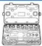 Torque Socket Wrench Torque Socket Wrench |  Marker Pen Vacuum Cleaner Marker Pen Vacuum Cleaner |  |
 Torque Wrench Torque Screwdriver Steel Tape Torque Wrench Torque Screwdriver Steel Tape |  |  Level Ruler Level Ruler | |
 Electric Batch(with M6 socket) Electric Batch(with M6 socket) |  Multimeter Rubber Mallet Multimeter Rubber Mallet |  |  Wire Stripper Wire Stripper |
 Wire Cutting Pliers Wire Cutting Pliers |  Crimping Pliers(for PV terminals) Crimping Pliers(for PV terminals) | 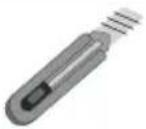 Art Knife Art Knife |  RJ45 crimping Pliers RJ45 crimping Pliers |
 Crimping Pliers(for AC terminals) Crimping Pliers(for AC terminals) |  |  Hot Air Gun Hot Air Gun |  Heat Shrink TubeCal Heat Shrink TubeCal |
 Anti-dirt Blanket Anti-dirt Blanket |  PV Plug Unlocking Tool PV Plug Unlocking Tool | ||
Personal Protective Equipment
 |  |  |  |
| Safety Gloves Safety Goggles | Dust Mask | Safety Shoes | |
4.3 Installation Process
4.3.1 Battery Pack Installation
The battery pack height must comply with local regulations. If the positioning plate conflicts with the regulations, the regulations must be met first.
Step 1: Determine the position of the base: mainly determine the distance from the wall; The distance from the wall is 65 mm , and keep horizontal;

Step 2: Use 4 units of M5*14mm screws to secure the battery bracket on the battery modules and secure the battery bracket and mounting bracket with 4 units of the same. Both sides need to be installed.

Step 3: Use phillips four head screws and a three M5x14 unit to install the battery pack, and wall battery mounts. As shown in the following figure.

Step 4: Use a marker to draw dots at the red intersection in the following image. After drawing the dots, remove the wall battery pendant and use a drill bit to drill holes.

Step 5: Install expansion bolts in the drilled holes. Use the expansion bolt with its own M8 nut to fix the wall battery pendant with the expansion bolt. Afterwards, use phillips head screws head screws with M5x14 to fix the wall battery mount and pack mount.

Step 6: Repeat steps 2 to 5 to install the other battery modules required. Please align the lower battery with the front of the upper battery during installation.

Step 7: After installing the battery module, place the BMS control box on top of the battery box. Please align the BMS control box with the front of the lower battery during installation.

4.3.2 Inverter Installation
Step 1: Open the inverter hood covers on both sides and place the inverter vertically on the BMS control box. It will build the connection between the inverter and BMS of the control box via PACK and inverter connection cable.

Step 2: Place the inverter on the BMS main box, fix the inverter on the mounting bracket, adjust the whole system, and ensure that the battery and inverter are firmly hung on the panel and bracket.

5 Electrical Connection
5.1 Battery System Cable Connection
The HEC2-BHP system (without inverter) is cableless installation design which includes pre-installed internal connections. The modular stack installation directly plug-in and completes the series connection between battery modules. The connection between the confirm from R&D about the BMS box model number system (from BMS main box) and the inverter requires a cable connection using PCS-BAT connector which includes power connection, communication and grounding. Also, there's a separate grounding connection between BMS main box and inverter.

5.2 PV Connection

- Before connecting to PV modules, please install a separately DC circuit breaker between inverter and PV modules.
- It is very important for system safety and efficient operation to use appropriate cable for PV module connection. To reduce risk of injury, please use the proper recommended cable size as below.
| Wire Size | Cable( mm2 ) |
| 12AWG 4 |

• To avoid any malfunction, do not connect any PV modules with possible current leakage to the inverter. For example, grounded PV modules will
- When selecting proper PV modules, please be sure to consider below parameters:
1) Open circuit Voltage ( Voc ) of PV modules not exceeds max. PV array open circuit voltage of inverter.
2) Open circuit Voltage ( Voc ) of PV modules should be higher than minimum. starting voltage.
Max. DC Voltage Limitation
| Model | HEC2-S3.68Hr2 | HEC2-S3.8Hr2 | HEC2-S5.0Hr2 | HEC2-S6.0Hr2 |
| Max. DC Voltage (V) | 600 | 600 | 600 | 600 |
| MPPT Voltage Range (V) | 100-540 | 100-540 | 100-540 | 100-540 |
Connection Steps:
Step 1: Checking PV module.
1.1 Use voltmeter to measure module array voltage.
1.2 Check the PV+ and PV- from the PV string combiner box correctly.
1.3 Please make sure the impedance between the positive pole and negative pole of PV to earth should be MΩ level.
Step 2: Separating the DC connector.

Step 3: Wiring
3.1 Choose the 4 mm 2 wire to connect with the cold-pressed terminal.
3.2 Remove 10mm of insulation from the end of wire.
3.3 Insert the insulation into pin contact and use crimping plier to clamp it.

Step 4: Insert pin contact through the cable nut to assemble into back of the male or female plug. When you feel or heard a "click" sound the pin contact assembly is seated correctly.

Step 5: Plug the PV connector into the corresponding PV connector on inverter.
5.3 AC Input/Output Connection
Before connecting the grid connection, please install a separate AC circuit breaker between inverter and AC input power source. This will ensure the inverter can be securely disconnected during maintenance and fully protected from over current of AC input. The recommended rating of AC circuit breaker is 32A.
Table Cable and Micro-breaker recommended
| Model | HEC2-S3.68Hr2 | HEC2-S3.8Hr2 | HEC2-S5.0Hr2 | HEC2-S6.0Hr2 |
| Cable | 6mm2 | 6mm2 | 6mm2 | 6mm2 |
| AC breaker | 32A | 32A | 32A | 32A |

Warning!
There is "L" "N" "PE" Symbols marked inside the connector; the Line wire of grid must be connected to "L" terminal; the Neutral wire of grid must be connected to "N" terminal; the Earth of grid must be connected to "PE
Required for installation.
Installation tools: open-end wrench, wire stripper, 2.0 Allen driver, 6-side Rivet pliers, etc.
Installation tools

open-end wrench wire stripper


2.0 Allen driver

6-side Rivet pliers
a: Use professional tools to peel off the cables according to the requirements in the table below.

| No. | clarification | Size data |
| A | Outer diameter of wire | 12mm-18mm |
| B | Bare wire length | 31±5mm |
| C | Wire length | 9±0.5mm |
—: CAUTION: NOT FOR INTERRUPTING CURRENT" and "ATTENTION: NE PAS UTILISER POUR COUPER LE COURANT"
—. "Not for Current Interrupting"
b: Insert the conductor into the suitable ferrule acc. to DIN 46228-4 and crimp the contact.

6mm² non-insulated cord end Terminal Recommended model : EN6012
c: Unscrew the swivel nut from the threaded sleeve and thread the swivel nut and threaded sleeve over the AC cable.

Crimp the terminals with crimping pliers.

Set the parts on the cable, Insert the terminal holes in sequence.

Crimp the wire with a hexagonal screwdriver and turn the screw. torque 1.2+/-0.1N· m ( 2.56mm2 ) 1.0+/-0.1N· m ( ≤2.0mm2 )
Note: It is necessary to wire according to the L, N, and PE labeling instructions of the plug-in.

Insert the main body into the rubber core and hear the "click" sound.

Tighten the nut with an open-ended wrench (torque 2.5 ± 0.5 N·m).

complete the installation
Male and female butt (plate end)

The installation arrow indicates insertion the male connector.

complete the installation
Plate end to unlock instructions

Place the unlocking tool onto the corresponding product.
Press the button on the unlocking tool with your finger or a flathead screwdriver
Pull the product outwards to complete the split
Note: The disassembling and assembling methods and procedure operation for the male plug-in is the same as that for the female plug-in.
5.4 Communication Interface Connection

5.4.1 PM(METER/CT) Interfaces
This interface is connection to electricity meter or CT. The electricity meter should be mounted and connected at the grid transition point (feed-in point) so that it can measure the grid reference and feed-in power. The communication about PCS and meter/CT is RS485. This port is used for 485 communication between 2 external CT channels and an electric meter. Currently CT1 is enabled and CT2 is reserved. The meter communication uses RS485 interface to read the voltage, current, active power, reactive power, apparent power and other information collected by the meter. Before communicating with the meter, the baud rate and address information of the meter need to be set through the "Solarman Business APP".
| Pin | Description | Pin | Description |
| 1 | 485A | 5 | GND |
| 2 | 485B | 6 | CT2B |
| 3 | CT2A | 7 | CT1A |
| 4 | VCC | 8 | CT1B |

*Refer to 5.4 for wiring sequence
Interface Description
-
The installer will prepare the network cable and the length of the cable will be determined according to the site environment.
-
Remove the cable insulation and make the RJ45 connector according to the cable line order
-
Open the CT cap, place it on the grid main line "L" cable so that the arrow of the CT points towards the direction of the power grid, and then close the cap.


- Connect the S1 and S2 cables of the CT to the RJ45 adapter, and connect the wires as shown in the diagram.


- Plug both ends of the RJ45 cable into the RJ45 adapters and the PCS interface.

Notice
Note:
Make sure the grid main power and PV switch are closed during the installation.

Notice
CT should be placed near the power grid. If ammeter test pass but inverter still can't achieve export power (power is not controllable or always 0 power output). Please check installation location of the CT.
5.4.2 DRM Port Connections (Optional)
This interface is a dry contact (only for Australia). DRED means demand response enable device. The AS/NZS 4777.2:2020 required inverter needs to support demand response mode (DRM). This function is for inverter that comply with AS/NZS 4777.2:2020 standard. Inverter is fully complied with all DRM. The corresponding functions are enabled by DRED equipment and host computer. For details, refer to AS4777. A RJ45 terminal is used for DRM connection
| Pin | Description | Pin | Description |
| 1 | DRM1/5 | 5 | REF |
| 2 | DRM2/6 | 6 | COM |
| 3 | DRM3/7 | 7 | VCC |
| 4 | DRM4/8 | 8 | GND |

*Refer to 5.4 for wiring sequence.
Interface Description
DEMAND RESPONSE MODES (DRMs)
| Mode | Pin | Description |
| DRM 0 | Operate the disconnection device | |
| DRM 1 | Do not consume power | |
| DRM 2 | Do not consume at more than 50% of rated power | |
| DRM 3 | Do not consume at more than 75% of rated power AND Source reactive power if capable | |
| DRM 4 | Increase power consumption (subject to constraints from other active DRMs) | |
| DRM 5 | Do not generate power | |
| DRM 6 | Do not generate at more than 50% of rated power | |
| DRM 7 | Do not generate at more than 75% of rated power AND sink reactive power if capable | |
| DRM 8 | Increase power generation (subject to constraints from other active DRMs) |
5.4.3 COM/LCD Interface
This interface is a dry contact. COM port uses RS485 communication, the communication protocol is the same as WIFI port 485 protocol, used for client power grid scheduling monitoring.
| Pin | Description | Pin | Description |
| 1 | D02A | 5 | GND |
| 2 | D02B | 6 | 485B |
| 3 | 485A | 7 | D01A |
| 4 | VCC | 8 | D01B |
*Refer to 5.4 for wiring sequence.

Interface Description
5.4.4 PARALLEL(INV) Interface
This interface is used to implement the inverter parallel function. The communication between parallel inverters is CAN.
| Pin | Description | Pin | Description |
| 1 | CANH | 5 | MCANL |
| 2 | NC | 6 | CANL |
| 3 | NC | 7 | NC |
| 4 | MCANH | 8 | NC |
*Refer to 5.4 for wiring sequence.

Interface Description
5.5 External Smart Meter (optional) Connection
You must connect external CTs or a smart grid meter between the inverter and the power grid. If you want to connect a smart meter, note that only one meter is necessary for each inverter. The meter must be mounted and connected at the grid transition point (feed-in point) so that it can measure the grid reference and feed-in power.
PROCEDURE
STEP1: Prepare the communication wires, power cable, and tools for the meter connection.
STEP2: Selection of a suitable position location for fixing the DIN track, Mount the Meter on the DIN track.
STEP3: Installation of CT. Refer to the introduction of CT installation for specific steps.
STEP4: Install the cables correctly as shown.

Wiring of Smart Meter Connection (Example, ACRIORH-D10TE)
5.6 Earth Fault Alarm Connection
The inverter complies with IEC 62109-2 13.9. The fault indicator LED on the inverter cover will light up and the app will push a message of an error code of F40 indicating the earthing fault,
The inverter should be installed at eye level for convenient maintenance (Adjust the height by placing the foundation)
5.7 Wiring Diagram
HEC Hybrid Series is designed with two EPS versions for customer to choose based on the local rules.
E Version applies to the wiring rules that requires the Live line and N (Neutral) line of EPS must be disconnected with the Live line and N (Neutral) line of grid (applies to most of the countries).
![graph TD A["Solar Array"] --> B["Battery"] B --> C["Ground stud in the lower left corner"] D["Hybrid Inverter"] --> E["BMS"] E --> F["Battery"] F --> G["Ground stud in the lower left corner"] H["Distribution Box"] --> I["RCD"] I --> J["Back-up Loads"] H --> K["CT"] K --> L["Grid"] M["N-BAR"] --> N["…](/content/2026/05/1045188/images/496a8be14cee9d0c87cc2ecde4cf2239ad19cda25dc1d4425f831017a6bdad35.jpg)
E Version
For Australia, New Zealand. The neutral points on the GRID side and the LOAD side must be connected together, otherwise the LOAD function does not work.
PE grounding:
- The PE terminal of LOAD is vacant and cannot be connected to the grid system of Australia, New Zealand and South Africa.
- There are two PE earthing posts on the PCS shell, one is connected to the shell earthing post of the BMS control box to maintain earthing continuity between different structural parts, and the other PE earthing post needs to be reliably connected to the building earthing ring network nearby.
![graph TD A["Solar Array"] --> B["Battery"] B --> C["Distribution Box"] C --> D["RCD"] D --> E["Back-up Loads"] C --> F["CT"] F --> G["Grid"] G --> H["N-BAR"] H --> I["E-N Link"] I --> J["E-BAR"] J --> K["Normal Loads"] L["Solar Array"] --> M["Battery"] M --> N["Battery"] O["The Grounding screw hole…](/content/2026/05/1045188/images/92baf9a6bbc72e26cf2b540c427d681798bf3926440239287f4725dc402b34ca.jpg)
I Version
5.8 Battery Pack Capacity Expansion
- Capacity 10.2 kWh: 2× battery module+1× BMS control box+ 1×base
• Capacity 15.3 kWh: 3× battery module+1× BMS control box+1×base - Capacity 20.4 kWh: 4× battery module+2× BMS control box+2×base
- Capacity 30.6 kWh: 6× battery module+2× BMS control box+2×base

Parallel cable for BMS control box (2×BMS control box need)

Notice
After completing the product installation, end users are not supported to expand the battery capacity by themselves, the battery pack capacity must be determined before installation.
6 System Operation
6.1 Switch On
When turning on the system, it is very important to follow the steps below to prevent damage to the system.
WARNING: Please check the installation again before turning on the system.

Power-on process:
Step 1: Open the protective cover and close the BMS control box circuit breaker
Step 2: Press the BMS control box button and check the status of the light strip
Step 3: Turn on the photovoltaic isolation switch
Step 4: Turn on the grid-side circuit breaker
6.2 Switch Off
Step 1: Turn off the grid-side circuit breaker
Step 2: Turn off the PV disconnect switch
Step 3: Open the protective cover and turn off the BMS control box circuit breaker
7 Plant Monitoring
Owners can create their own plant at SOLARMAN Platform to run a real-time monitoring. System will collect the data from associated devices, which enables a full understanding of PV plant running status.
Distributors and installers can create plant while installing the system and can authorize the end user so they can check and monitor their own plants. Meanwhile, the distributors can do the O&M remotely for an effective and pro-active service delivery towards the end users ensuring customer satisfaction.
7.1 Download SOLARMAN APP
SOLARMAN Web is remote monitoring and controlling platform for all the users. There are all the identities available.
https://www.solarmanpv.com/
SOLARMAN Business APP:
SOLARMAN Business APP: SOLAR-MAN Business is remote monitoring and controlling platform for the distributors, dealers and Installers.
(Before the installation, please contact with HICONICS to get an authorized account).

SOLARMAN Business APP
SOLARMAN Smart APP:
SOLARMAN Smart is remote monitoring and controlling platform for the end users. The installer can help the end users to create the Smart accounts in SOLARMAN Business.

SOLARMAN Smart APP
Note:
Note: For detailed configuration procedures, please log in
"https://www.hiconics.com/en/product/product-detail/prod-detail?productId=100448" for the latest "HICONICS Generation 2 (Hienergy) SOLARMAN Configuration Guide".
8 Maintenance and Troubleshooting
8.1 Maintenance Before Operation
- Before the inverter is put into operation, read the instruction manual carefully, and strictly execute the connection and installation of the equipment according to the instructions on the manual.
- Carefully check whether the various parts of the inverter as well as the terminals are loose and fall off in the process of transporting.
- Carefully check whether the diameter of each wire of the inverter is in accordance with the requirements; whether the proper insulation is good or not; and whether the grounding of the system is in accordance with the insulation regulations or not.
Note: When using the inverter, it should be operated in strict accordance with the instructions for using and maintaining the inverter, and the warning signs on the inverter should be intact. Maintenance of inverter during operation.
8.2 Maintenance During Operation
-
In the process of inverter commissioning, regularly check whether the inverter wirings are firm, and check whether the dust net, fan, power module, terminals and other parts are working normally.
-
The inverter cabinet has high pressure, usually should pay attention to check whether the cabinet door is locked or not.
-
When the room temperature exceeds 30° C, effective cooling measures should be taken to prevent the inverter from overheating and burning.
-
The structure and electrical connection of the inverter should be kept intact, and there should be no corrosion, accumulation of dust, etc. The inverter should not have large vibration and abnormal noise during operation.
-
Regularly disconnect the circuit breaker of AC output side of the inverter once.
-
When the DC bus capacitor temperature in the inverter is too high or exceeds the service life, it should be found and replaced in time.
-
the inverter belongs to high reliable operation equipment, can achieve long-term trouble-free operation, weekdays should carry out inspections, listen to the inverter sound is normal, the external debris, whether the vent is dusty, the panel display is normal, found that the problem is dealt with in a timely manner, report.
Note: Non-professionals should not disassemble and overhaul the inverter without permission. Inverter generally have short circuit, over current, over voltage, overheating and other items of automatic protection, when the problem occurs, do not need to manually shut down.
9 Fault Information
9.1 System Fault Information
| NO. | Fault name | Solution |
| 1 | NVM checksum failure | Disconnect the AC output switch, DC input switch and Battery switch, then connect them 5 minutes later. Contact the dealer or the after-sales service if the problem persists. |
| 2 | DSP communication failure | Disconnect the AC output switch, DC input switch and Battery switch, then connect them 5 minutes later. Contact the dealer or the after-sales service if the problem persists. |
| 3 | BMS communication failure | Disconnect the AC output switch, DC input switch and Battery switch, then connect them 5 minutes later. Contact the dealer or the after-sales service if the problem persists. |
| 4 | Battery overvoltage alarm | Disconnect the AC output switch, DC input switch and Battery switch, then connect them 5 minutes later. Contact the dealer or the after-sales service if the problem persists. |
| 5 | Battery undervoltage alarm | Disconnect the AC output switch, DC input switch and Battery switch, then connect them 5 minutes later. Contact the dealer or the after-sales service if the problem persists. |
| 6 | Battery overtemperature alarm | Disconnect the AC output switch, DC input switch and Battery switch, then connect them 5 minutes later. Contact the dealer or the after-sales service if the problem persists. |
| 7 | Battery under temperature alarm | Disconnect the AC output switch, DC input switch and Battery switch, then connect them 5 minutes later. Contact the dealer or the after-sales service if the problem persists. |
| 8 | Battery overcurrent alarm | Disconnect the AC output switch, DC input switch and Battery switch, then connect them 5 minutes later. Contact the dealer or the after-sales service if the problem persists. |
| 9 | Battery voltage difference too large | Disconnect the AC output switch, DC input switch and Battery switch, then connect them 5 minutes later. Contact the dealer or the after-sales service if the problem persists. |
| 10 | Temperature difference too large | Disconnect the AC output switch, DC input switch and Battery switch, then connect them 5 minutes later. Contact the dealer or the after-sales service if the problem persists. |
| 11 | Battery SOC too high | Disconnect the AC output switch, DC input switch and Battery switch, then connect them 5 minutes later. Contact the dealer or the after-sales service if the problem persists. |
| 12 | Battery SOC too low | Disconnect the AC output switch, DC input switch and Battery switch, then connect them 5 minutes later. Contact the dealer or the after-sales service if the problem persists. |
| 13 | Other battery alarms | Disconnect the AC output switch, DC input switch and Battery switch, then connect them 5 minutes later. Contact the dealer or the after-sales service if the problem persists. |
9.2 Inverter Fault Information
| NO. | Fault name | Solution |
| 1 | Grid over voltage | 1. If the problem occurs occasionally, the utility grid may be temporarily abnormal. The inverter will recover automatically after detecting that the utility grid is normal.2. If the problem occurs frequently, check whether the grid voltage is within the permissible range.• Contact the local power company if the grid voltage exceeds the permissible range.• Modify the overvoltage protection threshold, HVRT or disable the overvoltage protection function after obtaining the consent of the local power company if the grid frequency is within the permissible range.3. Check whether the AC breaker and the output cables are connected securely and correctly if the problem persists. |
| 2 | Grid under voltage | 1. If the problem occurs occasionally, the utility grid may be abnormal temporarily. The inverter will recover automatically after detecting that the utility grid is normal.2. If the problem occurs frequently, check whether the grid voltage is within the permissible range.• Contact the local power company if the grid voltage exceeds the permissible range.• Modify the undervoltage protection threshold, LVRT or disable the undervoltage protection function after obtaining the consent of the local power company if the grid frequency is within the permissible range.3. Check whether the AC breaker and the output cables are connected securely and correctly if the problem persists. |
| 3 | Grid over current | 1. If the problem occurs occasionally, the utility grid may be abnormal temporarily. The inverter will recover automatically after detecting that the utility grid is normal.2. Contact the dealer or the after-sales service if the problem occurs frequently. |
| 4 | Grid frequency abnormal | 1. If the problem occurs occasionally, the utility grid may be abnormal temporarily. The inverter will recover automatically after detecting that the utility grid is normal.2. If the problem occurs frequently, check whether the grid frequency is within the permissible range.• Contact the local power company if the grid frequency exceeds the permissible range.• Modify the frequency protection threshold or disable the over frequency protection function after obtaining the consent of the local power company if the grid frequency is within the permissible range. |
| 5 | DC bus over voltage | Disconnect the AC output switch, DC input switch and Battery switch, then connect them 5 minutes later. Contact the dealer or the after-sales service if the problem persists. |
| 6 | DC bus under voltage | Disconnect the AC output switch, DC input switch and Battery switch, then connect them 5 minutes later. Contact the dealer or the after-sales service if the problem persists. |
| 7 | PCS over temperature | 1. Check the ventilation and the ambient temperature at the installation point.2. If the ventilation is poor or the ambient temperature is too high, improve the ventilation and heat dissipation.3. Contact the dealer or after-sales service if both the ventilation and the ambient temperature are normal. |
| 8 | PV over temperature | 1. Check the ventilation and the ambient temperature at the installation point.2. If the ventilation is poor or the ambient temperature is too high, improve the ventilation and heat dissipation.3. Contact the dealer or after-sales service if both the ventilation and the ambient temperature are normal. |
| 9 | PVA over current | Disconnect the AC output switch, DC input switch and Battery switch, then connect them 5 minutes later. Contact the dealer or the after-sales service if the problem persists. |
| 10 | PVB over current | Disconnect the AC output switch, DC input switch and Battery switch, then connect them 5 minutes later. Contact the dealer or the after-sales service if the problem persists. |
| 11 | Buck-Boost A over current | Disconnect the AC output switch, DC input switch and Battery switch, then connect them 5 minutes later. Contact the dealer or the after-sales service if the problem persists. |
| 12 | Buck-Boost B over current | Disconnect the AC output switch, DC input switch and Battery switch, then connect them 5 minutes later. Contact the dealer or the after-sales service if the problem persists. |
| 13 | Battery side DC over voltage | 1. If the problem occurs occasionally, check battery input voltage, if it's within normal range, the inverter will recover automatically.2. Contact the dealer or the after-sales service if the problem occurs frequently. |
| 14 | Battery side DC under voltage | 1. If the problem occurs occasionally, check battery input voltage, if it's within normal range, the inverter will recover automatically.2. Contact the dealer or the after-sales service if the problem occurs frequently. |
| 15 | PVA over voltage | Check the serial connection of the PV array. Make sure that the open circuit voltage of the PV string is not higher than the maximum operating voltage of the inverter. |
| 16 | PVB over voltage | Check the serial connection of the PV array. Make sure that the open circuit voltage of the PV string is not higher than the maximum operating voltage of the inverter. |
| 17 | Ambient abnormal | 1. Check the ventilation and the ambient temperature at the installation point.2. If the ventilation is poor or the ambient temperature is too high, improve the ventilation and heat dissipation.3. Contact the dealer or after-sales service if both the ventilation and the ambient temperature are normal. |
| 18 | Residual Current Fault | 1. If the problem occurs occasionally, it may be caused by a cable exception. The inverter will recover automatically after the problem is solved.2. Check whether the impedance between the PV string and PE is too low if the problem occurs frequently or persists. |
| 19 | Hardware abnormal | Disconnect the AC output switch, DC input switch and Battery switch, then connect them 5 minutes later. Contact the dealer or the after-sales service if the problem persists. |
| 20 | Recharge precharge | Disconnect the AC output switch, DC input switch and Battery switch, then connect them 5 minutes later. Contact the dealer or the after-sales service if the problem persists. |
| 21 | Insulation fault | 1. Check whether the resistance of the PV string to PE exceeds 50kΩ. If no, check the short circuit point.2. Check whether the PE cable is connected correctly.3. If the resistance is lower on rainy days, please reset the ISO. |
| 22 | AC side relay abnormal | Disconnect the AC output switch, DC input switch and Battery switch, then connect them 5 minutes later. Contact the dealer or the after-sales service if the problem persists. |
| 23 | PVA Reverse Connection Fault | Check whether the PV strings are connected reversely. |
| 24 | PVB Reverse Connection Fault | Check whether the PV strings are connected reversely. |
| 25 | Hardware DC Bus Over Voltage | Disconnect the AC output switch, DC input switch and Battery switch, then connect them 5 minutes later. Contact the dealer or the after-sales service if the problem persists. |
| 26 | Hardware Battery Over Voltage | Disconnect the AC output switch, DC input switch and Battery switch, then connect them 5 minutes later. Contact the dealer or the after-sales service if the problem persists. |
| 27 | Grid 10 minutes Over Voltage | 1. If the problem occurs occasionally, the utility grid may be abnormal temporarily. The inverter will recover automatically after detecting that the utility grid is normal.2. If the problem occurs frequently, check whether the grid voltage is within the permissible range.• Contact the local power company if the grid voltage exceeds the permissible range.• Modify the grid overvoltage rapid protection threshold after obtaining the consent of the local power company if the grid voltage is within the permissible range. |
| 28 | EPS(Off-grid) Overload Fault | 1. If the problem occurs occasionally, the EPS load may be abnormal temporarily. The inverter will recover automatically after few minutes.2. If the problem occurs frequently, check whether the EPS load is within the permissible range.3. Contact the dealer or the after-sales service if the problem persists. |
| 29 | Fan Fault | Disconnect the AC output switch, DC input switch and Battery switch, then connect them 5 minutes later.Contact the dealer or the after-sales service if the problem persists. |
| 30 | DC Relay Fault | Disconnect the AC output switch, DC input switch and Battery switch, then connect them 5 minutes later.Contact the dealer or the after-sales service if the problem persists. |
| 31 | Power Meter Communication Fault | 1. Check the Meter is working properly and the cable connection from Power meter to inverter is normal.2. Disconnect the AC output switch, DC input switch and Battery switch, then connect them 5 minutes later.3. Contact the dealer or the after-sales service if the problem persists. |
| 32 | Reserved | 1. If the problem occurs occasionally, the EPS load may be abnormal temporarily. The inverter will recover automatically after few minutes.2. If the problem occurs frequently, check whether the EPS load is within the permissible range.3. Contact the dealer or the after-sales service if the problem persists. |
10 Packaging, Transportation, Storage
• The system cabinet is packed in cardboard packaging and the internal PE packaging bag is moisture-proof and waterproof.
• Use EPE pearl cotton foam pad in the middle to prevent damage to the system during handling and transportation.
- Transportation must comply with UN3480's dangerous goods transportation and local laws and regulations.
• The system is heavy and must use the mechanical handling.
• Transportation temperature: -10 °C \~ 40 °C.
• The equipment and packaging cannot be sprayed, so it cannot be transported in the open air.
• Storage temperature:
- -20 °C \~ 35 °C, 12month;
- -20 °C \~ 45 °C, 3month;
- -20 °C \~ 55 °C, 1month;
(The SOC before storage is kept in the range of 30% to 60%)
• Storage humidity: 0%\~95%RH (No condensation)
- The storage room should be kept ventilated, the room should be clean and dry, and it should be protected from dust and moisture.
- The storage time can be up to 3 months. It is recommended to charge and discharge the system for more than the time.
• Storage room sunlight cannot be directly exposed to the system.
Annex 1: Inverter Parameter Table
| Technical Data | HEC2-S6.0Hr2 | HEC2-S5.0Hr2 | HEC2-S3.8Hr2 | HEC2-S3.68Hr2[7] |
| PV Input | ||||
| Max.PV array power | 3750 W/3750 W | |||
| Max.DC voltage | 600 V [3] | |||
| Nominal DC operating voltage | 360 V | |||
| MPPT voltage range | 100 V-540 V | |||
| MPP voltage range for nominal power [5] | 225 V-480 V | 85 V-480 V 141 | V-480 V 137 V-480 V | |
| Start up voltage | 120 V | |||
| Max.input current(A/B) | 15 A/15 A | |||
| Max.short circuit current(A/B) | 18 A/18 A | |||
| No.of MPP tracks/String per MPP tracker | 2/1 | |||
| BAT Side | ||||
| Battery voltage range | 85V [4]- 400 V | |||
| Battery voltage range for nominal power | 250 V-400 V | 225 V-400 V 170 | V-400 V 160 V-400 V | |
| Recommended battery voltage | 300 V | |||
| Max.charge/discharge current [2] | 25 A/25 A | |||
| Communication interfaces | RS485/CAN | |||
| Reverse connect protection | Yes | |||
| AC Grid Side(On-grid) | ||||
| Nominal AC output power | 6000 W [1] | 5000 W [1] | 3800 W | 3680 W |
| Max.Output Power | 6000 W [1] | 5000 W [1] | 3800 W | 3680 W |
| Nominal Apparent Power Output to Utility Grid | 6000 VA [1] | 5000 VA [1] | 3800 VA | 3680 VA |
| Max. Apparent Power Output to Utility Grid | 6000 VA [1] | 5000 VA [1] | 3800 VA | 3680 VA |
| Nominal Apparent Power from Utility Grid | 6000 VA | 5000 VA | 3800 VA | 3680 VA |
| Max. Apparent Power from Utility Grid | 6000 VA | 6000 VA [6] | 6000 VA [6] | 6000 VA [6] |
| Nominal grid voltage | L/N/PE 230V | |||
| Grid Voltage Range | 180 V-280 V | |||
| Nominal grid frequency | 50 Hz | |||
| AC Grid Frequency Range | 50 Hz±5 Hz | |||
| Max. output AC current to Utility Grid | 26.1 A | 21.7 A | 16.5 A | 16 A |
| Rate output AC current to Utility Grid | 26.1 A | 21.7 A | 16.5 A | 16 A |
| Rated AC Current From Utility Grid | 26.1 A | 21.7 A | 16.5 A | 16 A |
| Max. AC Current From Utility Grid | 26.1 A | 26.1 A [6][6] [6] | 26.1 A | 26.1 A |
| Power factor | ~1 (Adjustable from 0.8 leading to 0.8 lagging) | |||
| I.THD | <3%@Rated power <5%@Rated power | |||
EPS Side
| Back-up Nominal Apparent Power | 6000 VA | 5000 VA | 3800 VA | 3680 VA |
| Nominal power | 6000 W | 5000 W | 3800 W | 3680 W |
| Max. Output Apparent Power without Grid | 7500VA@10sec | |||
| Max. Output Apparent Power with Grid | 7500VA@10sec | |||
| Nominal output voltage | L/N/PE 230V | |||
| Nominal output frequency | 50 Hz | |||
| Nominal Output Current | 26.1 A | 21.7 A | 16.5 A | 16 A |
| Max.output current | 26.1 A | 21.7 A | 16.5 A | 16 A |
| Max.output overcurrent protection | 32.6A@10sec | |||
| Switching from Grid Connected Mode to backup Mode | <20 ms | |||
| Output THD | <5%@Linear Load | |||
EFFICIENCY
| MPPT efficiency | 99.9% | 99.9% | 99.9% | 99.9% |
| Euro efficiency | 95.2% | 95.2% | 95.0% | 95.0% |
| Max.efficiency | 96.8% | 96.7% | 96.5% | 96.5% |
| Battery charge/discharge efficiency | 97.6%(PV-BAT) | 97.6%(PV-BAT) | 97.6%(PV-BAT) | 97.6%(PV-BAT) |
| 96.0%(BAT-AC) | 96.3%(BAT-AC) | 95.4%(BAT-AC) | 95.4%(BAT-AC) |
ENVIRONMENT LIMIT
| Ingress protection | IP65 |
| Protection class | Class I |
| Pollution degree | PD3 |
| Over voltage category | III (MAINS), II (DC) |
| Operating temperature range | -20 C ~+60 C (derating at +45) |
| Max. operation altitude | <2000m |
| Humidity | 0-95% |
| Cooling | Natural Convection |
| User Interface | LED,APP |
| Communication with BMS | CAN/485 |
| Communication with Meter | RS485 |
| Communication with Portal | WIFI |
| Typical noise emission | <40dB |
| Dimension (W*H*D) | 800 mm*450 mm*160 mm |
| Weight | 34 KG |
| Topology | Non-isolated |
| Self-consumption at Night | <25 W |
| DC Connector | MC4 (4~6 mm2) |
| AC Connector | Quick Plug |
| Storage Temperature | -40 °C to +85°C |
| Standard warranty | 5 years |
| STANDARD | |
| Safety | IEC/EN 62109-1&2, IEC 62477 |
| EMC | IEC 61000-6-1, IEC 61000-6-3 |
| Environment | IEC 60529,IEC 60068 |
| Efficiency | IEC 61683 |
| Certification | EN 50549-1,G99,G98,CEI 021,VDE 4105,AS/NZS 4777.2 |
Remark:
[1] The grid feed in power for VDE4105 is limited 4600VA.
[2] Battery charging current is limited 25A and power is limited 6000W.
[3] The machine may be damaged if PV port exceeds this voltage, full power operation voltage should be less than 480V, 480V-540V for limited power operation.
[4] Battery port boot voltage must be greater than 95V.
[5] The power is 6000W according to the grid port.
[6] The value will appear when the grid is charging battery and support EPS load.
[7] 3.68kW is UK only.
Annex 2: Battery Parameters
| Mode | HEC2-BHP50r2 | HEC2-BHP100r2 | HEC2-BHP150r2 | HEC2-BHP200r2-A | HEC2-BHP300r2 |
| Component | Base+BMS + 1*Module | Base+BMS + 2*Module | Base+BMS +3*Module | 2*(Base+BMS +2*Module) | 2*(Base+BMS +3*Module) |
| Nominal Voltage | 102.4 V | 204.8 V | 307.2 V | 204.8 V | 307.2 V |
| Maximum Protection Voltage | 116.8 V | 233.6 V | 350.4 V | 233.6 V | 350.4 V |
| Minimum Protection Voltage | 89.6 V | 179.2 V | 268.8 V | 179.2 V | 268.8 V |
| Number of Battery Modules | 1 | 2 | 3 | 4 | 6 |
| Nominal Capacity | 50 Ah | 50 Ah | 50 Ah | 100 Ah | 100 Ah |
| Total Energy | 5.1 kWh | 10.2 kWh | 15.3 kWh | 20.4 kWh | 30.6 kWh |
| Nominal Power | 2.56 kW | 5.12 kW | 7.68 kW | 10.24 kW | 15.36 kW |
| Nominal Charge/Discharge Current | 25A | 25A | 25A | 50A | 50A |
| Maximum Charge/Discharge Current | 25 A | 25 A | 25 A | 50 A | 50 A |
| Cycle Life | 6000 Cycles(@0.5C,90%DOD,25°C,60%SOH) | ||||
| Expected Life Time | 10 Years(60%SOH) | ||||
| Operating Ambient Temperature Range | -20 to 55 °C(derating above 45°C) | ||||
| Storage Temperature | -20°C to 55°C (1 months) | ||||
| -20°C to 45°C (3 months) | |||||
| -20°C to 35°C(1 year) | |||||
| Humidity | 0~95% | ||||
| Altitude | Below 2000 m | ||||
| Ingress Protection | IP65 | ||||
| System to Inverter | RS485/CAN2.0 | ||||
| Battery to Battery/BMS | Daisy chain | ||||
| Display Interface | LED | ||||
| Switch on/off | Button*1+Breaker*1 | Button*1+Breaker*1 | Button*1+Breaker*1 | 2* (Button*1+Breaker*1) | 2* (Button*1+Breaker*1) |
| Certificate | CE,IEC 62619,IEC 62040,IEC 60529,IEC 61000,UN 38.3 | ||||
| Hazardous Materials Classification | Class 9 | ||||
| Weight | 69±4 kg | 124±6 kg 1 | 79±8 kg 248±1 | 2 kg 358±16 kg | |
| External Dimension(W*H*D) | 800±20*530±30*160±20 mm | 800±20*840±30*160±20 mm | 800±20*1150±30*160±20 mm | 1600±20*840±30*160±20 mm | 1600±20*1150±20*160±20 mm |
| Remark | 1 Series 2 Series Parallel | ||||
- INSTRUCTION MANUAL
- HYBRID INVERTER SINGLE PHASE
- INTRODUCTION
- MULTI-LANGUAGE MANUAL QR CODE
- GENERAL NOTE ON GENDER EQUALITY
- CONTENTS
- 1 NOTES ON THIS MANUAL 01
- 3 INTRODUCTION 12
- 4 INSTALLATION 26
- 5 ELECTRICAL CONNECTION....33
- 6 SYSTEM OPERATION 47
- 7 PLANT MONITORING 48
- 8 MAINTENANCE AND TROUBLESHOOTING 49
- 9 FAULT INFORMATION 51
- 10 PACKAGING, TRANSPORTATION, STORAGE 56
- 1 NOTES ON THIS MANUAL
- 1.1 SCOPE OF VALIDITY
- 1.2 TARGET GROUP
- 1.3 SYMBOLS USED
- 1.4 EU DECLARATIONS OF CONFORMITY
- 2 SAFETY
- 2.1 NOTES ON THIS MANUAL EXPLANATION OF SYMBOL
- SYMBOL
- EXPLANATION
- 2.2 IMPORTANT SAFETY INSTRUCTIONS
- DANGER
- CAUTION
- NOTICE
- WARNING
- ANTI-ISLANDING EFFECT
- PE CONNECTION AND LEAKAGE CURRENT
- FOR UNITED KINGDOM
- FOR AUSTRALIA AND NEW ZEALAND
- BATTERY SAFETY INSTRUCTIONS
- 2.3 HANDLE HEAVY LOADS SAFELY
- 3 INTRODUCTION
- 3.1 BASIC FEATURES
- SYSTEM DIAGRAM
- 3.2 WORK MODES
- SELF USE
- BACK UP
- PEAK SAVING
- 3.3 PACKING LIST
- 3.4 SYSTEM APPEARANCE
- 3.5 WIRING PORT PART
- 3.5.1 INVERTER
- NOTE
- 3.5.2 BMS CONTROL BOX
- 3.5.3 BATTERY PACK
- 3.5.4 BASE
- 3.6 LED LIGHTS DISPLAY DEFINE
- 3.6.1 BATTERY SYSTEM LED DISPLAY DEFINE
- 3.6.2 INVERTER LED INDICATIONS
- INSTALLATION
- 4.1 CHECK FOR PHYSICAL DAMAGE
- 4.2 EQUIPMENT INSTALLATION
- 4.2.1 REQUIREMENTS
- 4.2.2 REQUIRED FOR INSTALLATION
- 4.3 INSTALLATION PROCESS
- 4.3.1 BATTERY PACK INSTALLATION
- 4.3.2 INVERTER INSTALLATION
- 5 ELECTRICAL CONNECTION
- 5.1 BATTERY SYSTEM CABLE CONNECTION
- 5.2 PV CONNECTION
- CONNECTION STEPS
- 5.3 AC INPUT/OUTPUT CONNECTION
- REQUIRED FOR INSTALLATION
- INSTALLATION TOOLS
- MALE AND FEMALE BUTT (PLATE END)
- PLATE END TO UNLOCK INSTRUCTIONS
- 5.4 COMMUNICATION INTERFACE CONNECTION
- 5.4.1 PM(METER/CT) INTERFACES
- 5.4.2 DRM PORT CONNECTIONS (OPTIONAL)
- 5.4.3 COM/LCD INTERFACE
- 5.4.4 PARALLEL(INV) INTERFACE
- 5.5 EXTERNAL SMART METER (OPTIONAL) CONNECTION
- PROCEDURE
- 5.6 EARTH FAULT ALARM CONNECTION
- 5.7 WIRING DIAGRAM
- PE GROUNDING
- 5.8 BATTERY PACK CAPACITY EXPANSION
- 6 SYSTEM OPERATION
- 6.1 SWITCH ON
- POWER-ON PROCESS
- 6.2 SWITCH OFF
- 7 PLANT MONITORING
- 7.1 DOWNLOAD SOLARMAN APP
- SOLARMAN BUSINESS APP
- SOLARMAN SMART APP
- 8 MAINTENANCE AND TROUBLESHOOTING
- 8.1 MAINTENANCE BEFORE OPERATION
- 8.2 MAINTENANCE DURING OPERATION
- 9 FAULT INFORMATION
- 9.1 SYSTEM FAULT INFORMATION
- 10 PACKAGING, TRANSPORTATION, STORAGE
- REMARK
Brand : V-TAC
Model : HEC2-S6.0Hr2
Category : Single-phase hybrid inverter