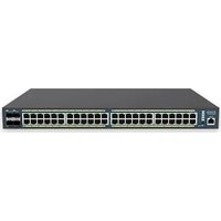
EWS1200-28TFP - Network switch ENGENIUS - Free user manual and instructions
Find the device manual for free EWS1200-28TFP ENGENIUS in PDF.


| Product Type | Managed Gigabit PoE+ Switch |
| Number of Ports | 24 x PoE+ 10/100/1000 + 4 x SFP+ 10G |
| PoE Budget | 370W total |
| Form Factor | 1U Rackmount |
| Dimensions (W x D x H) | 440 x 370 x 44 mm |
| Weight | 5.5 kg (12.1 lbs) |
| Power Supply | Internal AC 100-240V, 50-60Hz |
| Max Power Consumption | 450W |
| Switching Capacity | 128 Gbps |
| Management | Web GUI, CLI, SNMP, Telnet |
| VLAN Support | 802.1Q, up to 4096 VLANs |
| Quality of Service (QoS) | 802.1p, DSCP, per-port prioritization |
| Spanning Tree Protocol | STP, RSTP, MSTP |
| Link Aggregation | 802.3ad, up to 8 groups |
| Security | 802.1X, ACL, Port Security |
| Cooling | 2 x Smart Fans |
| Operating Temperature | 0°C to 45°C (32°F to 113°F) |
| Storage Temperature | -20°C to 70°C (-4°F to 158°F) |
| Maintenance | Clean with dry cloth; keep vents clear |
| Spare Parts & Repairability | No user-serviceable parts; contact support |
| Warranty | 5 years limited hardware warranty |
Frequently Asked Questions - EWS1200-28TFP ENGENIUS
User questions about EWS1200-28TFP ENGENIUS
0 question about this device. Answer the ones you know or ask your own.
Ask a new question about this device
Download the instructions for your Network switch in PDF format for free! Find your manual EWS1200-28TFP - ENGENIUS and take your electronic device back in hand. On this page are published all the documents necessary for the use of your device. EWS1200-28TFP by ENGENIUS.
USER MANUAL EWS1200-28TFP ENGENIUS
Gigabit Managed Smart Switch with Wireless Controller

IMPORTANT
To install this device please refer to the Quick Installation Guide included in the product packaging.
Table of Contents
Product Overview....7
Introducon 8
Key Features....9
System Requirements ....10
Package Contents....10
Technical Specicaons....11
Getting Started....14
Installing the Switch....15
Management Interface 15
Connecng the Switch to a Network 16
Software Features....18
Using the Switch....19
Wireless Controller Features....20
Managing EWS Access Points....20
Device Management....22
Summary 22
Access Points....24
Access Point Sengs....29
AP Groups....42
Access Control....44
Wireless Services....46
Monitor 47
Acve Clients....47
Rogue AP Detecon 49
System Log 51
Email Alert....56
Visualizaon 60
Topology View....60
Map View 63
Floor View 65
Stascs 70
Access Points....70
Wireless Clients....71
Real Time Throughput....72
Hotspot Services 73
Capve Portal....73
Guest Account....75
Maintenance 76
Schedule Tasks 76
Troubleshoong 77
Bulk Upgrade....78
One-Click Update 79
SSL Cercate....82
Check Codes 84
Migraon to ezMaster 85
Ethernet Switch Features 86
System....86
Summary 86
IP Sengs....87
System Time 90
Port Sengs....92
PoE 94
EEE....97
L2 Feature....98
Link Aggregaon....98
STP....105
MAC Address Table 116
LLDP....118
IGMP Snooping 122
MLD Snooping....128
Jumbo Frame....131
VLAN....132
802.1Q....133
PVID....134
Management VLAN 136
Voice VLAN 137
Management....140
System Informaon....140
User Management 141
Dual Image 142
SNMP 143
ACL 152
MAC ACL....153
MAC ACE 154
IPv4 ACL....156
IPv4 ACE 157
IPv6 ACL....159
IPv6 ACE 160
ACL Binding 162
QoS....163
Global Setngs 164
CoS Mapping....165
DSCP Mapping....166
Port Sengs....167
Storm Control....169
Security 171
802.1x....171
RADIUS Server....175
Access....176
Port Security....180
Port Isolaon....181
DoS....182
Monitoring....184
Port Stascs....184
RMON....185
Log....190
Diagnoscs....195
Cable Diagnoscs 195
Ping Test 196
IPv6 Ping Test 197
Trace Route 198
Maintenance....199
Conguraon Manager....199
Firmware Upgrade 200
Appendix 201
Appendix A - Federal Communicaton Commission Interference Statement 202
Appendix B - IC Interference Statement 203
Appendix C - CE Interference Statement 204
Chapter 1
Product Overview

Introduction
The EnGenius EWS Series of Wireless Management Switches is an aordable centralized wired/wireless management system developed specifically for entry-level small-to-medium businesses. This powerful device can be easily deployed and operated by non-tech experts and installed eortless and quickly. Any organizaon with limited IT engineer and budget can create a stable and secure wireless network in no me. The system integrates seamlessly with existing routers, switches, rewalls, authencaon servers and other network devices, and can be placed within any network, congured to act as a both a Wireless Controller as well as a Layer 2 Gigabit switch, providing robust and centralized management of the whole network through one powerful system. With no additional costs or license purchasing necessary, network administrators can manage and monitor both wired and wireless nodes through a single web interface.
The system can automatically discover any supported EnGenius EWS Series Access Points connected to the network with a simple click of a mouse, self-congure and become instantly manageable. Simply log into the device via any standard web browser and assign APs into cluster groups. Wireless radio, wireless security and other wireless related conguraons can all be easily applied to mulple APs simultaneously, eliminating the me consuming process of conguring each and every Wireless Access Points individually.
The user friendly GUI provides instant access to a variety of client and network informaon including Managed AP List, Auto Discovered AP List, Cluster Grouping List, and Client List with complete MAC/IP Address, Incoming/Outgoing Trac, Wireless Output Power and other relevant informaon. Stascs of AP and client tracs are automatically generated into easy-to-understand graphs, providing a visual representation of the network trac.
Not to forget the Topology View feature that allows administrators to quickly see the whole wired/wireless network topology at real-me for easier planning, troublesomeong and monitoring, as well as Floor Plan View and Map View which allows for quickly locang deployed APs, a helpful feature for large scale AP deployment and mul-site management. There's also an Intelligent Diagnoscs feature for administrators to check the status of Wireless APs and provide easy troublesomeong for oine units and even capable of reboong APs remotely.
Key Features
10/100/1000 Mbps Gigabit Ethernet Ports
Dedicated SFP slots for longer connecvity via ber uplinks and for uplink redundancy and failover
IGMP and MLD snooping provides advanced mulcast Itering
IEEE802.3ad Link Aggregaon
STP/RSTP/MSTP
Access Control List/ Port Security
IEEE802.1X and RADIUS Authencaon
RMON
SNMP v1/v2c/v3
Voice VLAN for fast and reliable deployment of VoIP
Energy Ecient Ethernet (IEEE802.3az) support for better energy saving when more EEE-compliant end devices are available in the market
Advanced QoS with IPv4/IPv6 ingress trac ltering (ACLs) and priorizaon
Easy to manage via Web-Based Management GUI for switch deployment
Standard-based technology, ensuring interoperability with any standard-based devices in the exisng network
Dual rmware images, improving reliability and upme for your network
System Requirements
The following are the minimum system requirements in order to concur the device:
Computer with an Ethernet interface or wireless network capability
Windows OS (XP, Vista, 7, 8), Mac OS, or Linux-based operang systems
Web-Browsing Applicaon (i.e. Internet Explorer, Firefox, Chrome, Safari, or another similar browser applicaon)
Package Contents
The package contains the following items (all items must be in package to issue a refund):
Technical Specifications
General
| EWS1200D-10T | EWS1200-28T | EWS1200-52T | |
| 10/100/1000Mbps Ports | 8 | 24 | 48 |
| 100/1000Mbps SFP Slots | 2 | 4 | 4 |
| RJ45 Console Ports | - | 1 | 1 |
| Forwarding Mode | Store-and-Forward | ||
| SDRAM | 256 MB | 256 MB | 256 MB |
| Flash Memory | 32 MB | 32 MB | 32 MB |
| Packet Buer Memory | 512 KB | 512 KB | 1.5 MB |
| EWS2910P | EWS5912FP | EWS7928P | EWS7928FP | EWS7952FP | |
| 10/100/1000Mbps Ports | 8 | 10 | 24 | 24 | 48 |
| 100/1000Mbps SFP Slots | 2 | 2 | 4 | 4 | 4 |
| RJ45 Console Ports | - | 1 | 1 | 1 | 1 |
| PoE Standard | IEEE 802.3 af | IEEE 802.3 af/at | |||
| PoE Capable Ports | Port 1-8 | Port 1-8 | Port 1-24 | Port 1-24 | Port 1-48 |
| Total PoE Power Budget | 55W | 130W | 185W | 370W | 740W |
| Forwarding Mode | Store-and-Forward | ||||
| SDRAM | 256 MB | 256 MB | 256 MB | 256 MB | 256 MB |
| Flash Memory | 32 MB | 32 MB | 32 MB | 32 MB | 32 MB |
| Packet Buer Memory | 512 KB | 512 KB | 512 KB | 512 KB | 1.5 MB |
Software Features
Wireless Management Features
Access Point Auto Discovery and Provisioning
Access Point Auto IP Assignment
Access Point Group Management
Visual Topology View
Floor Plan View
Map View
Access Point Status Monitoring
Wireless Client Monitoring
Wireless Trac & Usage Stascs
Real-me Throughput Monitoring
Bulk Firmware Upgrade Capability
Remote Access Point Reboong
Fast Roaming
Band Steering
Trac Shaping
Intelligent Diagnoscs
Access Point Device Name Eding
Access Point Radio Sengs
RSSI Threshold
Access Point Client Liming
Wireless Security (WEP, WPA/WPA2 Enterprise,
WPA/WPA2 PSK)
VLANs for Access Point- Mulple SSIDs
Guest Network
Secure Control Messaging (SSL Cercate)
Local MAC Address Database
Remote MAC Address Database (RADIUS)
Conguraon Import / Export
L2 Features
802.3ad Link Aggregaon
- Maximum of 8 groups/8 ports per group
Port Mirroring
- One-to-One
- Many-to-One
Spanning Tree Protocol
- 802.1D Spanning Tree Protocol (STP)
- 802.1w Rapid Spanning Tree Protocol (RSTP)
- 802.1s Mulple Spanning Tree Protocol (MSTP)
MAC Address Table
- 8K entries
Stac MAC Address
- 256 entries
802.1ab Link Layer Discovery Protocol
IGMP Snooping
- IGMP v1/v2/v3 Snooping
- Supports 256 IGMP groups
- IGMP per VLAN
- IGMP Snooping Querier
- IGMP Snooping Fast Leave
MLD Snooping
- MDL Snooping v1/v2
- Supports 256 MLD groups
- IGMP per VLAN
Jumbo Frame
- Up to 9216 bytes
802.3x Flow Control
802.3az Energy Ecient Ethernet
VLAN
802.1Q support
VLAN Group
- Max 4094 stac VLAN groups
Voice VLAN
QoS
802.1p Quality of Service
- 8 queues per port
Queue Handling
- Strict
- Weighted Round Robin (WRR)
QoS based on:
- 802.1p Priority
- DSCP
Bandwidth Control
- Port-based (Ingress/Egress, 64 Kbps\~1000
Mbps)
Broadcast/Unknown Mulcast/ Unknown Unicast
Storm Control
Access Control List (ACL)
Layer 2/3
- Support maximum 32 entries (ACL)
- Support maximum 256 entries (ACE)
ACL based on:
- MAC address
- VLAN ID
- 802.1p priority
- Ethertype
- IP address
- Protocol type
- DSCP
Security
802.1X
- Guest VLAN
- Port-based Access Control
Supports RADIUS Authencaon
Port Security
- up to 256 MAC Addresses per port
Port Isolaon
DoS Aack Prevenon
BPDU Aack Prevenon
Monitoring
Port Stascs
System Log
RMON
Management
Web Graphical User Interface (GUI)
Command Line Interface (CLI)
BootP/DHCP Client/DHCPv6 Client
SSH Server
Telnet Server
TFTP Client
HTTPS
SNMP
- Supports v1/v2c/v3
SNMP Trap
SNTP
Conguraon restore/backup
Dual Images
Diagnosc
Cable Diagnosc
Ping Test
Trace Route
MIB/RFC Standards
RFC1213
RFC1493
RFC1757
RFC2674
RFC 2863
Environment Specifications
Operang Temperature
0 to 40°C (EWS1200D-10T, EWS2910P)
0 to 50°C (EWS1200-28T/52T, EWS5912FP,
Humidity (Non-condensing)
5% - 95%
Physical Specifications
Dimensions (W x D x H)
EWS1200D-10T, EWS2910P: 240x105x27mm
EWS5912FP: 330x230x44mm
EWS1200-28T/52T, EWS7228P: 440x260x44mm
EWS7928FP: 440x310x44mm
EWS7952FP: 440x410x44mm
Chapter 2
Getting Started

Installing the Switch
This secon will guide you through the installaon process.
Management Interface
The Switch features an embedded Web interface for the monitoring and management of your device.
Management Interface Default Values
IP Address: 192.168.0.239
Username: admin
Password: password
Connecting the Switch to a Network
Discovery in a Network with a DHCP server
Use the procedure below to setup the Switch within a network that uses DHCP.
- Connect the supplied Power Cord to the Switch and plug the other end into an electrical outlet. Verify the power LED indicator is lit on the Switch.
- Wait for the Switch to complete boong up. It might take a minute for the Switch to completely boot up.
- Connect one end of a Category 5/6 Ethernet cable into the Gigabit (10/100/1000Mpbs) Ethernet port on the Switch front panel and the other end to the Ethernet port on the computer. Verify that the LED on the Ethernet ports of the Switch are Green.
- Once your computer is on, ensure that your TCP/IP is set to On or Enabled. Open Network Connecons and then click Local Area Connecon. Select Internet Protocol Version 4 (TCP/IPv4). If your computer is already on a network, ensure that you have set it to a Stac IP Address on the Interface (Example: 192.168.0.10 and the Subnet mask address as 255.255.255.0).
- Open a web browser on your computer. In the address bar of the web browser, enter 192.168.0.239 and press Enter.
- A login screen will appear. By default, the username is admin and the password is password. Enter the current password of the Switch and then click Login. To make access to the web-based management interface more secure, it's highly recommended that you change the password to something more unique.
- Click IP Setngs under the System tab and select IPv4 or IPv6.
- Click DHCP under Auto-Conguraon.
- Click Apply to save the sengs.
- Connect the Switch to your network (DHCP enabled).
- On the DHCP server, nd and write down the IP address allocated to the device. Use this IP address to access the management interface.
Discovery in a Network with a DHCP server
This secon describes how to set up the Switch in a network without a DHCP server. If your network has no DHCP service, you must assign a stac IP address to your Switch in order to log in to the web-based management interface.
- Connect the supplied Power Cord to the Switch and plug the other end into an electrical outlet. Verify the Power LED indicator is lit on the Switch.
- Wait for the Switch to complete boong up. It might take a minute or so for the Switch to completely boot up.
- Connect one end of a Category 5/6 Ethernet cable into the Gigabit (10/100/1000Mbps) Ethernet port on the Switch front panel and the other end to Ethernet port on the computer. Verify that the LED on Ethernet ports of the Switch are Green.
- Once your computer is on, ensure that your TCP/IP is set to On or Enabled. Open Network Connecons and then click Local Area Connecon. Select Internet Protocol Version 4 (TCP/IPv4).
- If your computer is already on a network, ensure that you have set it to a Stac IP Address on the Interface (Example: 192.168.0.239 and the Subnet mask address as 255.255.255.0).
- Open a web browser on your computer. In the address bar of the web browser, enter 192.168.0.239 and press Enter.
- A login screen will appear. By default, the username is admin and the password is password. Enter the current password of the Switch and then click Login. To make access to the web-based management interface more secure, it's highly recommended that you change the password to something more unique.
- Click IP Setngs under the System menu and select Stac IP to congregate the IP sengs of the management interface.
- Enter the IP address, Subnet mask, and Gateway.
- Click Apply to update the system.
Chapter 3
Software Features

Using the Switch
Besides the funcons of a Wireless Controller, the EWS Wireless Management Switch also possesses funcons of a full-featured Layer 2 Ethernet Switch. Use the Controller / Switch tab on the upper le corner of the user interface to toggle between the Wireless Controller or Layer 2 Switch funcons.


Wireless Controller Features
Managing EWS Access Points
- Access Points in the network will be automatically discovered by the EWS and will be listed under the AP(s) Detected list in the Access Point menu.

- Select the Access Point(s) you wish to manage and click Add.
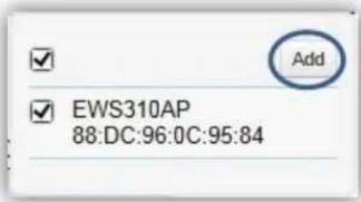
- You will be prompted to assign the IP Address under the IP Assignment screen.

| Auto-Conguraon | DHCP: You can choose to auto assign IP address if there is a DHCP server in the network.Stac: If you wish to manually assign the IP address, choose Stac. Enter the IP address you wish to assign to the AP and ll in the subnet mask, default gateway and DNS server address.Keep AP's Sengs: Select this opon for the AP to use its current network sengs. |
| IP Address | Enter the IP address for the Access Point. |
| Subnet Mask | Enter the subnet mask for the Access Point. |
| Default Gateway | Enter the default gateway for the Access Point. |
| Primary DNS Server | Enter the primary DNS server name. |
| Secondary DNS Server | Enter the secondary DNS server name (if necessary). |
- Click Apply and the Access Point(s) you've congured will be moved to the Managed list. Note that the status of the AP will change from Connecng to Provisioning to Online. Once the status turns Online, your Access Point(s) have been successfully added to the Managed list.
| Status | Model Name | MAC Address | Device Name | IP Address | Group |
| Online | EWS310AP | 88:DC:96:0C:95:84 | EWS310AP | 10.0 85.69 |
Note: If the status shows Incompatible Version, please check and make sure that the rmware of the Access Point and Switch are compatible.
| Status | Model Name | MAC Address | Device Name | IP Address | Group |
| Incompatible Version | EWS310AP | 88:DC:96:0C:95:84 | EWS310AP | 10.0 85.162 |
Device Management
Summary
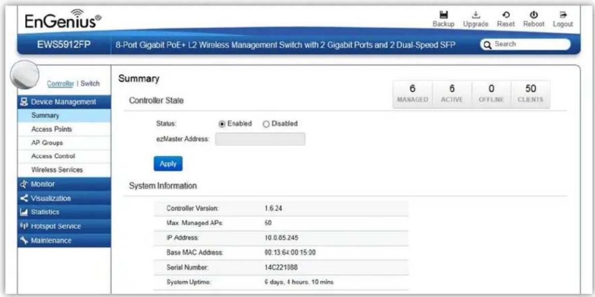
The Summary page shows general system informaon for the EWS Switch including the Controller Status, the soware version, the maximum number of APs the system can manage, MAC Address, IP Address, serial number, and system upme for the system.
Dashboard
The Dashboard on the upper right corner of the GUI shows the current status of EWS APs that has been managed by the EWS Switch.
| 6MANAGED | 6ACTIVE | 0OFFLINE | 13CLIENTS |
| Managed | This shows the number of APs currently managed by the EWS Switch. |
| Acve | This shows the number of managed APs that currently have an acve conncon with the EWS Switch. |
| Oine | This shows the number of managed APs that currently do not have an acve conncon with the EWS Switch. |
| Clients | This shows the total number of wireless clients currently connected to all the managed APs. |
Controller State
Status: Select whether to Enable or Disable the Controller feature on the Switch.
ezMaster Address: If you have an ezMaster server running and wants to have ezMaster manage this EWS Switch directly, enter the IP Address/domain name of the ezMaster server.
Click Apply to save the changes to the system.
System Informaon
• Controller Version: This is the soware version of the device.
• Max. Managed APs: The maximum number of APs the device is able to manage.
- IP Address: Displays the IP address of the device.
- Base MAC Address: Universally assigned network address.
- Serial Number: Displays the serial number of the device.
- System Upme: Displays the number of days, hours, and minutes since the last system restart.
Access Points
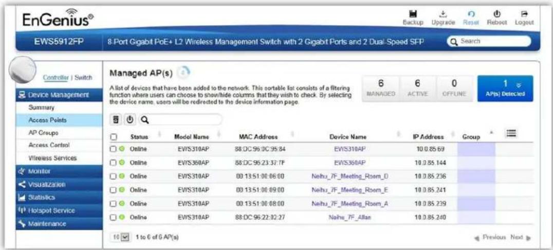
This page displays the status of all EWS Access Points that your Controller is currently managing as well as all the EWS Access Points in the network that the Controller has discovered. Use this page to add EWS Access Points to your EWS Controller Access Point list.
The EWS Switch is able to manage supported EWS Series Access Points. For the discovery procedure to succeed, the EWS Switch and the EWS Access Point must be connected in the same network. The EWS Switch can discover supported EWS Access Points with any IP address and Subnet sengs.
Managing Access Points
EWS Access Points can either be congured individually or congured as a group.
To manage an Access Point individually, click on the Device Name eld of the Access Point you wish to congure and you will be directed to a screen where you can congure sengs for the Access Point.
To manage Access Points as a group, go to Device Management > AP Clusters to create an AP group and add members into the group. Click on the Group eld of the AP you wish to conjure and you will be directed to a screen where you can conjure sengs for the AP Group.
Group sengs can be overridden by individual AP sengs. For example, if you want to set the transmit power to a lower seng for only a few specific APs, leave the Transmit Power at Auto in the Wireless
Radio Setngs of the AP Group, then click on the Device Name eld of the Access Point (which is already in a group) you wish to conjure and you will be directed to a screen where you can conjure override sengs for the selected Access Point.
Refresh Countdown Timer
This is the me le before the page auto-refreshes. The countdown is from 15 seconds.

Dashboard
The Dashboard shows the current status of all the EWS APs that has been managed by the EWS Switch.
| 6MANAGED | 6ACTIVE | 0OFFLINE |
| Managed | This shows the number of APs in the managed AP database that are congured with the EWS Switch. |
| Acve | This shows the number of managed APs that currently have an acve conncon with the EWS Switch. |
| Oine | This shows the number of managed APs that currently do not have an acve conncon with the EWS Switch. |
AP(s) Detected List
Reveals a list of all APs in the network that the EWS Switch automacally discovers. Mouse over the discovered Access Point to show general informaon such as the MAC address, IP address, model name and rmware version.

Remove AP
The Remove buon removes selected Access Point(s) from list. Access Points removed will be automacally set to standalone mode with all sengs restored to their factory default sengs.

Reboot AP
The Reboot buon will reboot the selected Access Point(s).

Search Bar
Use the Search Bar to search for Access Points managed by the EWS Switch using the following criteria: Status, model name, MAC Address, Device name, IP address, Firmware Version, Cluster.

Status
This indicates the current status of the managed Access Point.
| Status | Explanaon |
| Online | AP is connected and managed by EWS Switch. |
| Provisioning | AP is currently in the process of connecng to the EWS Switch. |
| Applying Change | AP is currently applying system changes. |
| Connecng | AP is currently connecng to EWS Switch. |
| Oine | AP is currently oine. |
| Reseng | AP is reseng. |
| Firmware Upgrading | AP is currently undergoing rmware upgrade process. |
| Invalid IP | The subnet of managed AP's IP address is not the same as the EWS Switch. Please remove AP and recongure AP to the correct seng. |
| Incompatible Version | AP rmware is not compatible with EWS Switch. |
| Checking Cercate | EWS Switch is checking the SSL Cercate of AP. |
Model Name
Shows the model name of the managed Access Point.
MAC Address
Shows the MAC address of the managed Access Point.
Device Name
Displays the device name of the managed Access Point.
- When the AP is not a cluster member, click on this eld and you'll be redirected to the conguraon page where you can edit sengs such as device name, IP Address, Wireless Radio sengs.
- When the AP is a cluster member, click on this eld to congregate settings for individual Access Points by overriding the cluster sengs.
IP Address
Shows the IP address of the managed Access Point.
Firmware Version
Shows the rmware version of the managed Access Point.
Last Update
Display the me the Access Point was last detected and the informaon was last updated.
Group
Displays the AP Group the Access Point is currently assigned to. Click on this eld and you'll be redirected to the group conguraon page.
Column Filter
Shows or hides elds in the Access Point list.

Access Point Settings
On this page, you can edit the AP's name and password, manually assign an IP address, or change the channel selecon, transmit power and other wireless sengs of a managed Access Point.
General Sengs

Device Name: The device name of the Access Point. Users can enter a custom name for the Access Point if they wish.
Administrator Username: Displays the current administrator login username for the Access Point. Enter a new Administrator username for the Access Point if you wish to change the username. The default username is: admin.
New Password: Enter a new password of between 1\~12 alphanumeric characters.
Verify Password: Enter the password again for conrmaon.
Auto Conguraon: Select whether the device IP address will use the stac IP address specied in the IP Address eld or be obtained automacally when the device connects to a DHCP server.
IP Address: Enter the IP address for the Access Point.
Subnet Mask: Enter the Subnet Mask for the Access Point.
Default Gateway: Enter the default Gateway for the Access Point.
Primary/Secondary DNS Server: Enter the Primary/Secondary DNS server name.
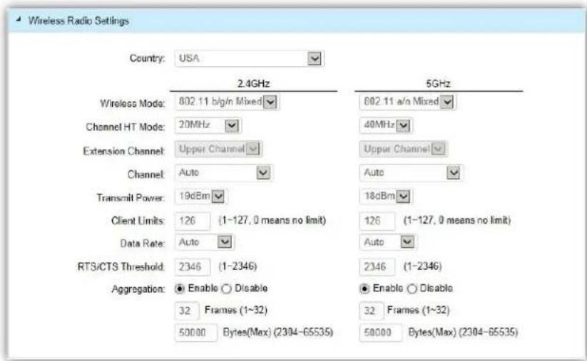
Country: Select a Country/Region to conform to local regulaons. Dierent regions have different rules that govern which channels can be used for wireless communicaons.
Wireless Mode: Select from the drop-down menu to set the wireless mode for the Access Point. For 2.4GHz, the available opons are 802.11b/g/n mixed, 802.11b, 802.11b/g mixed, 802.11g, and 802.11n. For 5GHz, the available opons are 802.11a/n mixed, 802.11a, and 802.11n.
Channel HT Mode: Use the drop-down menu to select the Channel HT as 20MHz, 20/40MHz or 40MHz. A wider channel improves the performance, but some legacy devices operate only on either 20MHz or 40 MHz. This opon is only available for 802.11n modes.
Extension Channel: Use the drop-down menu to set the Extension Channel as Upper or Lower channel. An extension channel is a secondary channel used to bond with the primary channel to increase this range to 40MHz allowing for greater bandwidth. This opon is only available when Wireless Mode is 802.11n and Channel HT Mode is 20/40MHz or 40MHz.
Channel: Use the drop-down menu to select the wireless channel the radio will operate on. Opmizing channel assignments reduces channel interference and channel ulizaon for the network, thereby improving overall network performance and increasing the network's client capacity. The list of available channels that can be assigned to radios is determined based on which country the Access Points are deployed in.
Transmit Power: Allows you to manually set the transmit power on 2.4GHz or 5GHz radios. Increasing the power improves performance, but if two or more Access Points are operating in the same area on the same channel, it may cause interference.
Client Limits: Specify the maximum number of wireless clients that can associate with the radio. Enter a range from 1 to 127, or ll in 0 for an unlimited client limit.
Data Rate: Use the drop-down list to set the available transmit data rates permied for wireless clients. The data rate aects the throughput of the access point. The lower the data rate, the lower the throughput, but the longer transmission distance.
RTS/CTS Threshold: Enter a Request to Send (RTS) Threshold value between 1\~2346. Use RTS/CTS to reduce data collisions on the wireless network if you have wireless clients that are associated with the same Access Point. Changing the RTS threshold can help control trac ow through the Access Point. If you specify a lower threshold value, RTS packets will be sent more frequently. This will consume more bandwidth and reduce the throughput of the Access Point. Sending out more RTS packets can help the network recover from interference or collisions which might occur on a busy network or on a network experiencing electromagnec interference.
Aggregaon: Select whether to enable or disable Aggregaon for the Access Point. This funcon merges data packets into one packet, reducing the number of packets. This also increases the packet sizes, so please keep this in mind. Aggregaon is useful for increasing bandwidth throughput in environments that are prone to high error rates. This mode is only available for 802.11n modes. Fill in the frame rate limit you wish to use. The range is from 1\~32. Next, ll in the max byte limit. The range is from 2304\~65535.
WLAN Sengs - 2.4GHz/5GHz
Under the WLAN Sengs, you can create and manage SSID conguraons and proles for the Access Points to t your needs. An SSID is basically the name of the wireless network to which a wireless client can connect to. Mulple SSIDs allow administrators to use a single physical network to support mulple applicaons with dierent conguraon requirements. Up to 8 SSIDs are available per radio. Click on the SSID you wish to make changes to and you'll be directed to the SSID Conguraon page.
WLAN Settings - 2.4GHz
| ID | Status | SSID | Security | Encryption | Hidden SSID | Client Isolation | L2 Isolation | VLAN Isolation | VLAN ID |
| 1 | Enabled | SNWL | WPA2-PSK | AES | No | No | No | No | 1 |
| 2 | Disabled | 210_2-2.4GHz | WPA2-PSK | AES | No | No | No | No | 2 |
| 3 | Disabled | SSID_3-2.4GHz | None | None | No | No | No | No | 3 |
| 4 | Disabled | SSID_4-2.4GHz | None | None | No | No | No | No | 4 |
| 5 | Disabled | SSID_5-2.4GHz | None | None | No | No | No | No | 5 |
| 6 | Disabled | SSID_6-2.4GHz | None | None | No | No | No | No | 6 |
| 7 | Disabled | SSID_7-2.4GHz | None | None | No | No | No | No | 7 |
| 8 | Disabled | SSID_8-2.4GHz | None | None | No | No | No | No | 8 |
| ID | The ID displays the SSID prole idener. |
| Status | This displays whether the current SSID prole is enabled or disabled. |
| SSID | Displays the SSID name as it appears to the wireless clients in the network. |
| Security | Displays the security mode the SSID uses. |
| Encrypon | Displays the data encrypon type the SSID uses. |
| Hidden SSID | Displays whether the hidden SSID is enabled or disabled. |
| Client Isolaon | Displays whether Client Isolaon feature is enabled or disabled. |
| L2 Isolaon | Displays whether L2 Isolaon feature is enabled or disabled. |
| VLAN Isolaon | Displays whether VLAN Isolaon feature is enabled or disabled. |
| VLAN ID | Displays the VLAN ID associated with the SSID.Note: For the Controller to funcon properly, make sure that all ports (on all cascading switches as well) connected to EWS APs on the switch are congured as the same VLAN ID as the Controller's Management VLAN ID. |
SSID Cong
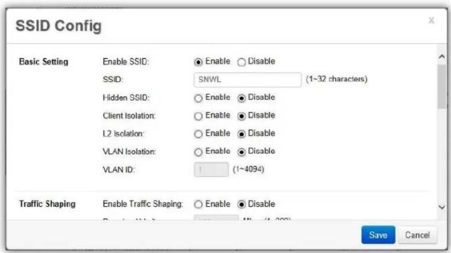
Enable SSID: Select to enable or disable the SSID broadcasts.
SSID: Enter the SSID for the current prole. This is the name that is visible to wireless clients on the network.
Hidden SSID: Enable this opon if you do not want to broadcast this SSID. This can help to discourage wireless users from connecng to a parcular SSID.
Client Isolaon: When enabled, all communicaon between wireless clients connected to the same AP will be blocked.
L2 Isolation: When enabled, wireless client traffic from all hosts and clients on the same subnet will be blocked.
VLAN Isolaon: When enabled, all communicaons between wireless clients and any other devices on dierent VLANs will be blocked. All frames from wireless clients connected to this SSID will be tagged a corresponded 802.1Q VLAN tag when going out from Ethernet port.
VLAN ID: Enter the VLAN ID for the SSID prole. The range is from 1\~4094. When VLAN tagging is congured per SSID, all data trac from wireless users associated to that SSID is tagged with the congured VLAN ID. Mulple SSIDs also can be congured to use the same VLAN tag. For instance, a single VLAN ID could be used to identify all wireless trac traversing the network, regardless of the SSID. When the AP receives VLAN-tagged trac from the upstream switch or router, it forwards that trac to
the correct SSID. The AP drops all packets with VLAN IDs that are not associated to the SSID.
Trac Shaping: Trafc Shaping regulates the allowed maximum downloading/uploading throughput per SSID. Select to enable or disable Wireless Trac Shaping for the SSID.
- Download Limit: Species the allowed maximum throughput for downloading.
- Upload Limit: Species the allowed maximum throughput for uploading.
Fast Roaming: This feature uses protocols dened in 802.11r to allow connuous connecvity for wireless devices in moon, with fast and secure roaming from one AP to another. Coupled with 802.11k, wireless devices are able to quickly identify nearby APs that are available for roaming and once the signal strength of the current AP weakens and your device needs to roam to a new AP, it will already know which AP is the best to connect with. Note that not every wireless client supports 802.11k and 802.11r. Both the SSID and security opons must be the same for this fast roaming to work. Fast Roaming is available when the following security methods are well congured:
| WPA2-Enterprise | RADIUS server required |
| WPA-Mixed Enterprise | |
| WPA2-PSK | No RADIUS server required |
| WPA-Mixed |
Security: Select encrypon method (WEP, WEP / WPA2 Enterprise, WPA-PSK / WPA2-PSK, or none) and encrypon algorithm (AES or TKIP).
WEP: Wired Equivalent Privacy (WEP) is a data encrypon protocol for 802.11 wireless networks which scrambles all data packets transmied between the Access Point and
the wireless clients associated with it. Both the Access Point and the wireless client must use the same WEP key for data encrypon and decrypon.
○ Mode: Select Open System or Shared Key.
- WEP Key: Select the WEP Key you wish to use.
- Input Type: ASCII: Regular Text or HEX. Select the key type. Your available opons are ASCII and HEX.
ASCII Key: You can choose upper and lower case alphanumeric characters and special symbols such as @ and #.
- HEX Key: You can choose to use digits from 0\~9 and letters from A\~F. Select the bit-length of the encrypon key to be used in the WEP conncon. Your available opons are: 64, 128, and 152-bit password lengths.
Key Length: Select the desired opon and ensure the wireless clients use the same seng. Your choices are: 64, 128, and 152-bit password lengths.
Key1/2/3/4: Enter the Key value or values you wish to use.
WPA / WPA2 Enterprise: WPA and WPA2 are Wi-Fi Alliance IEEE 802.11i standards, which include AES and TKIP mechanisms.
○ Type: Select the WPA type to use. Available opons are Mixed, WPA and WPA2. Choose Mixed if your network has a mixture of older clients that only support WPA and TKIP, and newer client devices that support WPA2 and AES.
Encrypon: Select the WPA encrypon type you would like. Your available opons are: Both, TKIP(Temporal Key Integrity Protocol) and AES(Advanced Encrypon Standard). Note: Since TKIP is not permied for 802.11n-based transmissions, seng the encrypon algorithm to TKIP when you are using an 802.11n or 802.11ac AP will cause the network to operate in 802.11g mode.
- RADIUS Server: Enter the IP address of the RADIUS server.
- RADIUS Port: Enter the port number used for connecons to the RADIUS server.
- RADIUS Secret: Enter the secret required to connect to the Radius server.
Update Interval: Specify how oen, in seconds, the group key changes. Select 0 to disable.
- RADIUS Accounting: Enables or disables the accoung feature.
- RADIUS Accounting Server: Enter the IP address of the RADIUS accounting server.
- RADIUS Accounting Port: Enter the port number used for connecons to the RADIUS accounting server.
- RADIUS Accounting Secret: Enter the secret required to connect to the RADIUS accounting server.
- Accounting Group Key Update Interval: Specify how oen, in seconds, the accoung data sends. The range is from 60\~600 seconds.
WPA-PSK / WPA2-PSK: WPA with PSK (Pre-shared key / Personal mode), designed for home and small oce networks that don't require the complexity of an 802.1X authencaon server.
Type: Select the WPA-PSK type to use. Available opons are Mixed, WPA-PSK and WPA2-PSK. Choose Mixed if your network has a mixture of older clients that only support WPA and TKIP, and newer client devices that support WPA2 and AES.
Encrypon: Select the WPA encrypon type you would like. Your available opons are: Both, TKIP(Temporal Key Integrity Protocol) and AES(Advanced Encrypon Standard). Note: Since TKIP is not permied for 802.11n-based transmissions, seng the encrypon algorithm to TKIP when you are using an 802.11n or 802.11ac AP will cause the network to operate in 802.11g mode.
○ WPA Passphrase: Enter the Passphrase you wish to use. If you are using the ASCII format, the Key must be between 8\~64 characters in length.
- Group Key Update Interval: Specify how oen, in seconds, the Group Key changes.
Advanced Sengs
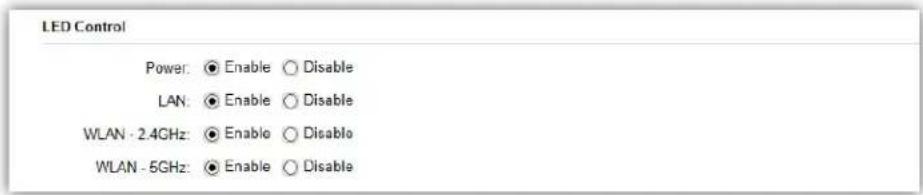
LED Control: In some environments, the blinking LEDs on APs are not welcomed. This opon allows you to enable or disable the devices LED indicators. Note that only indoor models support this feature.

Band Steering: When enabled, when the wireless client rst associates with the AP, the AP will detect whether or not the wireless client is dual-band capable, and if it is, it will force the client to connect to the less congested 5GHz network to relieve congeson and overcrowding on the mainstream 2.4GHz frequency. It does this by acvely blocking the client's aempts to associate with the 2.4GHz network.
Note: For Band Steering to take eect, both 2.4GHz and 5GHz SSIDs must have the same SSID and security sengs. Wireless clients must be in both 2.4GHz and 5GHz wireless coverage zone when authencang with the AP for the Band Steering algorithm to take eect.
- Prefer 5GHz: All dual-band clients with 5GHz RSSI above the threshold will be connected to the 5GHz band.
• Force 5GHz: All dual-band clients will connect to the 5GHz. - Band Balance: Automacally balances the number of newly connected clients across both 2.4GHz and 5GHz bands.
IMPORTANT INFORMATION: Band Steering only denies the acon when a wireless client associates with an AP for the rst me, and the wireless client must be in both 2.4GHz and 5GHz wireless coverage zone when authencating with the AP for the Band Steering algorithm to take eect.

RSSI Threshold: With this feature enabled, in order to minimize the me the wireless client spends to passively scanning for a new AP to connect to, the AP will send a disassociaon request to the wireless client upon detectng the wireless client's RSSI value lower than specied. The RSSI value can be adjusted to allow for more clients to stay associated to this Access Point. Note that seng the RSSI value too low may cause wireless clients to reconnect frequently. It is recommended to disable this feature unless you deem it absolutely necessary.

Management VLAN: Management VLAN can be used to separate management trac from regular network trac.
IMPORTANT INFORMATION: When conguring or updang AP's Management VLAN sengs, make sure that the same Management VLAN sengs are applied to the EWS Switch as well.

Guest Network: The Guest Network feature allows administrators to grant Internet connectivity to visitors or guests while keeping other networking devices and sensitive personal or company informaon private and secure.

Enable SSID: Select to enable or disable the SSID broadcasts.
SSID: Enter the SSID for the current prole. This is the name that is visible to wireless clients on the network.
Hidden SSID: Enable this opon if you do not want to broadcast this SSID. This can help to discourage wireless users from connecng to a parcular SSID.
Client Isolaon: When enabled, all communicaon between wireless clients connected to the same AP will be blocked.
Security: Select encrypon method (WPA-PSK / WPA2-PSK, or none) and encrypon algorithm (AES or TKIP).
WPA-PSK / WPA2-PSK: WPA with PSK (Pre-shared key / Personal mode), designed for home and small oce networks that don't require the complexity of an 802.1X authencaon server.
Type: Select the WPA-PSK type to use. Available opons are Mixed, WPA-PSK and WPA2-PSK. Choose Mixed if your network has a mixture of older clients that only support WPA and TKIP, and newer client devices that support WPA2 and AES.
Encrypon: Select the WPA encrypon type you would like. Your available opons are: Both, TKIP(Temporal Key Integrity Protocol) and AES(Advanced Encrypon Standard). Note: Since TKIP is not permied for 802.11n-based transmissions, seng the encrypon algorithm to TKIP when you are using an 802.11n or 802.11ac AP will cause the network to operate in 802.11g mode.
○ WPA Passphrase: Enter the Passphrase you wish to use. If you are using the ASCII format, the Key must be between 8\~64 characters in length.
- Group Key Update Interval: Specify how oen, in seconds, the Group Key changes.
Captive Portal Settings
Captive Portal:

Disable
Capve Portal: Select whether to Enable or Disable Capve Portal for Guest Network.
| Manual IP Settings | |
| IP Address: | 192.168.100.1 |
| Subnet Mask: | 255.255.255.0 |
| Automatic DHCP Server Settings | |
| Starting IP Address: | 192.168.100.100 |
| Ending IP Address: | 192.168.100.200 |
| WINS Server IP: | 0.0.0.0 |
Manual IP Sengs
• IP Address: Enter the IP address for the default gateway of clients associated to the Guest Network.
- Subnet Mask: Enter the Subnet mask for the Guest Network.
Automac DHCP Server Sengs
- Starng IP Address/Ending IP Address: Enter the pool range of IP addresses available for assignment.
- WINS Server IP: Specify the Windows Internet Naming Service (WINS) server address for the wireless network. WINS is a system that determines the IP address of a network computer with a dynamically assigned IP address, if applicable.
Aer sengs are changed, click Apply to save the changes to the system.
AP Groups
An AP Group can be used to denote conguraon opons and apply them to a number of APs at once. If your wireless network covers a large physical environment and you want to provide wireless services with dierent sengs and policies to dierent areas of your environment, you can use AP Groups to do this instead of having to modify the sengs of each AP individually. For example, if your wireless network covers two oors and you need to provide wireless access to visitors on the 1st Floor, you can simply setup two dierent AP Groups with dierent sengs and policies to suit your application.

Creang a New AP Group
Follow the steps below to create a new AP Group.
- Click on Add button to create a new AP Group.

-
Enter the name and descripon of the new AP Group.
-
In the Member Seng secon, all Access Points that are managed by the EWS Switch that are not currently assigned to an AP Group will be listed on the le. Select the Access Points you wish to assign to this group and press Add. The Access Points will be moved to the right column.
- Congure Radio, WLAN, and Advanced sengs then click on Apply for setngs to take eect.
Search Bar
Use the Search Bar to search for keywords in the list using the following criteria: AP Group Name, AP MAC, AP Name, Descripon.

Add Buon
Use the Add Buon to create a new AP Group.

Add
Edit Buon
Use the Edit Buon to edit the conguraons of the AP Group.

Delete Buon
Use the Delete Buon to remove an AP Group.

Access Control
This page displays the list of wireless clients previously blocked from your network. If for any reason, you need to block a client device from your network, you can do so from this page by creang a new rule and entering the client's MAC address.
Blocking a Specific Client Device
Follow the steps below to permanently block a specific client device from the network.
- Click the Add button to create a new block rule.
- Enter the MAC Address and Descripon of the wireless client device you wish to block.
- Click on Apply to create a new rule.
- Click on the Apply buon on the upper right to save sengs made on this page.
Unblocking a Previously Blocked Client Device
- Click on the Delete button on the client device you wish to unblock.
- Click on the Apply buon on the upper right to save sengs made on this page.

Blocked Clients
Displays the total number of clients permanently blocked from the network.
5
Blocked Client
Apply Buon
Click on Apply to save changes made on this page.
Apply
Search Bar
Use the Search Bar to search for blocked clients in the list using the following criteria: Client MAC Address, Descripon.

Add Buon
Use the Add Buon to add a new block rule.

Add
Edit Buon
Use the Edit Buon to edit the Client MAC Address or Descricon of the rule.

Delete Buon
Use the Delete Buon to remove the rule.

Wireless Services

Background Scanning
With Background Scanning enabled, the controller periodically samples RF acvity of all Access Points including channel ulizaon and surrounding devices in all available channels. Background scanning is the basis of Auto Channel, Auto Tx Power and Rogue AP detecon, and must be enabled for these features to operate. You may, if you prefer, disable it if you feel it's not helpful, or adjust the scanning frequency, if you want scans at greater or fewer intervals.
Note: For latency-sensitive applicaons such as VoIP, it is recommended to set the background scan interval to a higher value, e.g. 5 or 10 minutes. For regular applicaon, the recommended value is 30 seconds. This value will also be directly related on how long it takes for the AP to scan for rogue devices.
Auto TX Power
Using the informaon collected by Background Scanning, APs can automatically adjust their transmit power to opmize coverage. When enabled, APs will opmize their transmit power based on the me interval congured for Background Scanning.
Note: Background Scanning must be enabled and Tx Power of APs must be set to Auto (under Wireless Radio Sengs) for this feature to operate.
Monitor
Active Clients
From here, you can view informaon, temporarily disconnect and permanently block the wireless clients that are associated with the Access Points that the EWS Switch manages. The EWS Switch is able to identify client devices by their Operang System, device type and host name, if available. If mulple Access Points are connected to the network, use the search bar to nd an Access Point by its name.
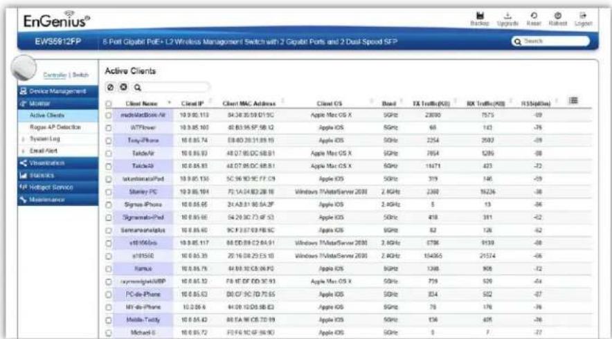
Kick Client
Use this funcon to temporarily disconnect a wireless client from the network. The disconnected client can simply reconnect manually if they wish to.

Ban Client
Use this funcon to permanently block a wireless client from the network.
Go to Device Management > Access Control to unblock the wireless client.

Search Bar
Use the Search Bar to search for Wireless Clients managed by the EWS Switch using the following criteria: Client Name, Client IP, Client MAC Address, Client OS, AP Device Name, AP MAC Address, Model Name, SSID, Band, TX Trac, RX Trac.

| Client Name | Displays the name of the wireless client connected to the Access Point. |
| Client IP | Displays the IP address of the wireless client connected to the Access Point. |
| Client MAC Address | Displays the MAC address of the wireless client connected to the Access Point. |
| Client OS | Displays the type of operang system the wireless client connected to the Access Point is running on. |
| AP Device Name | Displays the name of the Access Point which the client is connected to. |
| AP MAC Address | Displays the MAC address of the Access Point which the client is connected to. |
| Model Name | Displays the model name of the Access Point which the client is connected to. |
| SSID | Displays the SSID of the Access Point which the client is connected to. |
| Band | Displays whether the wireless client is connected to the 2.4GHz or 5GHz radio. |
| TX Trac (KB) | Displays the total trac transmied to the Wireless Client. |
| RX Trac (KB) | Displays the total trac received from the Wireless Client. |
| RSSI (dBm) | Displays the received signal strength indicator in terms of dBm. |
Rogue AP Detection
Rogue Access Points refer to those unauthorized and oen unmanaged APs aached to an exisng wired network which could bring harm to the network or may be used to deliberately gain access to condenal company informaon. With Background Scanning enabled, the Rogue AP Detecon feature can be used to periodically scan 2.4 GHz and 5 GHz frequency bands to identify rogue wireless Access Points not managed by the EWS Switch.
![EnGenius® EWS5912FP 8-Port Gigabit PoE+ L2 Wireless Management Switch with 2 Gigabit Ports and 2 Dual-Speed SFP Search Controller I Switch Device Management Monitor Active Clients Rogue AP Detection System Log Email Alert Visualization Statistics Hotspot Service Maintenance Rogue AP Detection 191 DETECTED BSSID SSID Channel Mode Band Security Detector 00:02:6F A3.41.F0 Tak-NAS 11 11b/gn 2.4GHz Open Neihu_7F_Meeting_Room_E (00:13:51:00:09:00) [RSSI-6I] 00:02:6F A3.41.F4 EnGeniusA041F4 36 11a/n 5GHz Open EWS310AP (08:DC:96:0C:95:84) [RSSI-8I] 00:02:6F C9.AF.18 EnGeniusC9AF1B 11 11b/gn 2.4GHz WEP Neihu_7F_Meeting_Room_A (00:13:51:00:08:00) [RSSI-7I] 00:02:6F DB.9F.F6 SNVL 1 11b/gn 2.4GHz WPA2-PSK Neihu_7F_Meeting_Room_E (00:13:51:00:09:00) [RSSI-8I] 00:0A.79 B2.09 T1 beautiful4 1 11b/g 2.4GHz WEP Neihu_7F_Meeting_Room_E (00:13:51:00:09:00) [RSSI-7I] 00:0C.55 FF.00 C1 CK_2.4g 9 11b/gn 2.4GHz WPA2-PSK Neihu_7F_Meeting_Room_E (00:13:51:00:09:00) [RSSI-6I] 00:0C.55 FF.00 C2 EnGenius*FF0CC2_1-5GHz 36 11acn 5GHz Open EWS360AP (08:DC:96:23:37:TF) [RSSI-7I] 00:12:0E B7.36 E4 4F 6 11b/gn 2.4GHz WPA-PSK mixed Neihu_7F_Meeting_Room_D (00:13:51:00:06:00) [RSSI-9I] 00:13.46 C2.4C FC Sapphire-TW 8 11b/g 2.4GHz WPA2-PSK Neihu_7F_Meeting_Room_D (00:13:51:00:06:00) [RSSI-8I] 00:13.61.0B.01.01 Test_1-2.4GHz 1 11b/gn 2.4GHz Open Neihu_7F_Meeting_Room_A (00:13:51:00:08:00) [RSSI-8I] 00:13.61.0D.01.01 EnGeniusOD0101_1-2.4GHz 1 11b/gn 2.4GHz Open Neihu_7F_Meeting_Room_A (00:13:51:00:08:00) [RSSI-8I] 00:13.61.0D.08.01 EnGeniusOD0801_1-2.4GHz 1 11b/gn 2.4GHz Open Neihu_7F_Meeting_Room_A (00:13:51:00:08:00) [RSSI-9I] 00:13.61.0E.01.01 Test_1-2.4GHz 1 11b/gn 2.4GHz Open Neihu_7F_Allan (88:DC:96:22:02:27) [RSSI-9I] 00:13.61.14.06.01 EnGenius14O6O1_1-2.4GHz 1 11b/gn 2.4GHz Open Neihu_7F_Meeting_Room_E (00:13:51:00:09:00) [RSSI-8I] 00:13.61.14.06.02 EnGenius14O6O2_1-5GHz 157 11acn 5GHz Open Neihu_7F_Meeting_Room_A (00:13:51:00:08:00) [RSSI-9I] 00:1C F8.38 CC.03 DIR-33G 6 11b/g 2.4GHz WPA-PSK mixed EWS310AP (88:DC:96:5C:95:84) [RSSI-9I] ENGENius*FF*FF*FF*FF*FF*FF*FF*FF*FF*FF*FF*FF*FF*FF*FF*FF*FF*FF*FF*FF*FF*FF*FF*FF*FF*FF*FF*FF*FF*FF*FF*FF*FF*FF*FF*FF*FF*FF*FF*FF*FF*FF*FF*FF*FF*FF*FF*FF*FF*FF*FA ENGENius*FF*FF*FF*FF*FF*FF*FF*FF*FF*FF*FF*FF*FF*FF*FF*FF*FF*FF*FF*FF*FF*FF*FF*FF*FF*FF*FF*FF*FF*FF*FF*FF*FF* ENGENius*FF*FF*FF*FF*FF*FF*FF*FF*FF*FF*FF*FF*FF*FF*FF*FF*FF*FF*FF*FF* ENGENius*FF*FF*FF*FF*FF*FF*FF*FF*FF*FF*FF*FF* ENGENius*FF/CC/CC/CC/CC/CC/CC/CC/CC/CC/CC/CC/CC/CC/CC/CC/CC/CC/CC/CC/CC/CC/CC/CC/CC/CC/CC/CC/CC/CC/CC/CC/CC/CC/CC/CC/CC/CC/CC/CC/CC/CC/CC/CC/CC/CC/CC/CC/CC/CC/CC/SC](/content/2026/05/1045026/images/db567c9e8b8f15b9ec4cff963334ddb1d4515487b4e060186aa720a5a6679eef.jpg)
Search Bar
Use the Search Bar to search for Rogue Access Points detected using the following criteria: BSSID, SSID, Type, Channel, Mode, Band, Security, Detector.

| BSSID | Displays the BSSID of the rogue device detected. |
| SSID | Displays the SSID of the rogue device detected. |
| Type | Displays the type of the rogue device detected. |
| Channel | Displays the channel of the rogue device detected. |
| Mode | Displays the wireless mode of the rogue device detected. |
| Band | Displays the band of the rogue device detected. |
| Security | Displays the encrypon method of the rogue device detected. |
| Detector | Displays the name and MAC address of the managed AP which detected the rogue device. |
Column Filter
Shows or hides elds in the list.

System Log
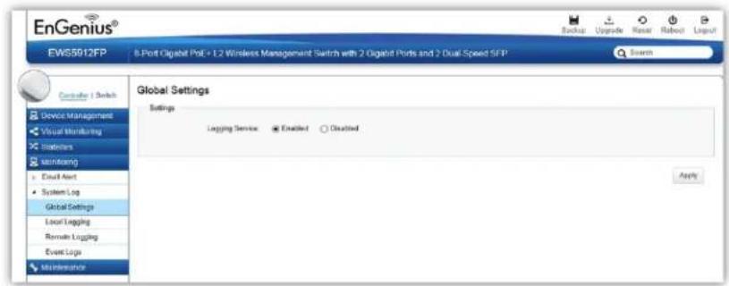
Global Settings
From here, you can Enable or Disable the Log sengs for the EWS Switch.
Local Logging
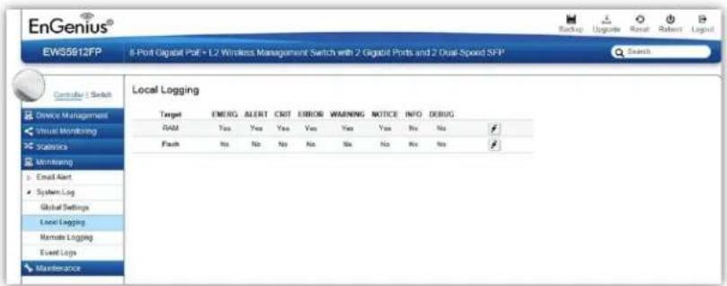
The System Log is designed to monitor the operaon of the EWS Switch by recording the event messages it generates during normal operaon. These events may provide vital informaon about system acvity that can help in the idencaon and soluons of system problems.
The EWS Switch supports log output to two direcons: Flash and RAM. The informaon stored in the system's RAM log will be lost aer the Switch is rebooted or powered o, whereas the informaon stored in the system's Flash will be kept eective even if the Switch is rebooted or powered off. The log has a xed capacity; at a certain level, the EWS Switch will start deleng the oldest entries to make room for the newest.
Severity Level
RFC 5424 denes eight severity levels:
| Code | Severity | Descripon | General Descripon |
| 0 | EMERG | System is unusable. | A "panic" condion usually aecng mulple apps/servers/sites. At this level it would usually nofy all tech sta on call. |
| 1 | ALERT | Acon must be taken immediately. | Should be corrected immediately, therefore nofy sta who can x the problem. An example would be the loss of a primary ISP conncon. |
| 2 | CRIT | Crical condions. | Should be corrected immediately, but indicates failure in a secondary system, an example is a loss of a backup ISP conncon. |
| 3 | ERROR | Error condions. | Non-urgent failures, these should be relayed to developers or admins; each item must be resolved within a given me. |
| 4 | WARNING | Warning condions. | Warning messages, not an error, but indicaon that an error will occur if acon is not taken, e.g. le system 85% full - each item must be resolved within a given me. |
| 5 | NOTICE | Normal but significant condion. | Events that are unusual but not error condions - might be summarized in an email to developers or admins to spot potenal problems - no immediate acon required. |
| 6 | INFO | Informaonal messages. | Normal operaonal messages - may be harvested for reporg, measuring throughput, etc. - no acon required. |
Remote Logging
The internal log of the EWS Switch has a xed capacity; at a certain level, the EWS Switch will start deleng the oldest entries to make room for the newest. If you want a permanent record of all logging advies, you can set up your syslog server to receive log contents from the EWS Switch. Use this page to direct all logging to the syslog server. Click the Add buon, dene your syslog server, and select the severity level of events you wish to log.

IP/Hostname
Specify the IP address or host name of syslog server.
Server Port
Specify the port of the syslog server. The default port is 514.
Severity Level
RFC 5424 denes eight severity levels:
| Code | Severity | Descripon | General Descripon |
| 0 | EMERG | System is unusable. | A "panic" condion usually aecng mulple apps/servers/sites. At this level it would usually nofy all tech sta on call. |
| 1 | ALERT | Acon must be taken immediately. | Should be corrected immediately, therefore nofy sta who can x the problem. An example would be the loss of a primary ISP conncon. |
| 2 | CRIT | Crical condions. | Should be corrected immediately, but indicates failure in a secondary system, an example is a loss of a backup ISP conncon. |
| 3 | ERROR | Error condions. | Non-urgent failures, these should be relayed to developers or admins; each item must be resolved within a given me. |
| 4 | WARNING | Warning conditions. | Warning messages, not an error, but indicaon that an error will occur if acon is not taken, e.g. le system 85% full - each item must be resolved within a given me. |
| 5 | NOTICE | Normal but significant condion. | Events that are unusual but not error conditions - might be summarized in an email to developers or admins to spot potenal problems - no immediate acon required. |
| 6 | INFO | Informaonal messages. | Normal operaonal messages - may be harvested for reporng, measuring throughput, etc. - no acon required. |
Facility
The log facility is used to separate out log messages by applicaon or by funcon, allowing you to send logs to dierent les in the syslog server. Use the drop-down menu to select local0, local1, local2, local3, local4, local5, local6, or local7.
Event Logs
This page displays the most recent records in the EWS Switch's internal log. Log entries are listed in reverse chronological order (with the latest logs at the top of the list). Click a column header to sort the contents by that category.

Display logs in
- RAM: The informaon stored in the system's RAM log will be lost aer the Switch is rebooted or powered o
- Flash: The informaon stored in the system's Flash will be kept effective even if the Switch is rebooted or powered o.
Type:
• Controller: Display controller related logs.
- Switch: Display switch related logs.
• All: Display logs for both controller and switch.
Export
Click Export buon to export the current buered log to a .txt le.
Clear
Click Clear buon to clear the buered log in the system's memory.
Email Alert
Alert Settings
If an alert is detected, the EWS Switch will record it in the event log. The EWS Switch can also be congured to send email nocaons for selected events.

Mail Alert State: Select whether to Enable/Disable email nocaaon.
Mail Informaon Seng
- SMTP Server: Enter the name of the mail server.
- SMTP Port: Enter the SMTP port.
- SSL/TSL: Enable this opon if your mail server uses SSL/TLS encrypon.
• Authencaon: Select this opon to enable authencaon. - User Name: Enter the username required by the mail server.
-
Password: Enter the password required by the mail server.
-
From Mail Address: Enter the email address that will appear as the sender of the email alert.
- To Mail Address: Enter the email address which the EWS Switch will send alarm messages to. You can only send alarm messages to a single email address.
- Subject: Enter the subject of the email nocaon.
Test: To verify that the EWS Switch can send email nocaons using the SMTP sengs you congured, click the Test buon.
Apply: Click Apply to save sengs.
Event Binding
Use this page to choose which types of events will trigger the EWS Switch to send an email nocaaon. When any of the selected events occur, the EWS Switch sends an email nocaaon to the email address that you specied in the Monitoring > Email Alert > Alert Sengs secon.

The table below provides explanaons for EWS Controller syslog event messages.
| Event Type | EWS Syslog Message | Severity Level |
| Status of AP Controller | Controller is enabled | INFO |
| Status of AP Controller | Controller is disabled | WARNING |
| Cercate Changed | SSL cercate updated | INFO |
| Cercate Changed | SSL cercate will expire in {value} days | WARNING |
| Cercate Changed | SSL cercate has expired | ERROR |
| Cercate Changed | [AP Name] [AP MAC]'s SSL cercate has been updated | INFO |
| AP Managed | [AP Name] [AP MAC] added to management list | INFO |
| AP Managed | [AP Name] [AP IP] removed from management list | INFO |
| Status of AP | [AP Name] [AP MAC] online | INFO |
| Status of AP | [AP Name] [AP MAC] reset | INFO |
| Status of AP | [AP Name] [AP MAC] oine | WARNING |
| Status of AP | [AP Name] [AP MAC] has invalid IP [IP Address] | WARNING |
| Status of AP | [AP Name] [AP MAC]'s acve client number reaches client limits {value} of [2.4/5]GHz | WARNING |
| AP Conguraon Changed | [AP Name] [AP MAC] conguraon updated | INFO |
| AP Firmware | [AP Name] [AP MAC] rmware version is incompatible | WARNING |
| AP Firmware | [AP Name] [AP MAC] started to upgrade rmware from [old-ver] to [new-ver] | INFO |
| AP Firmware | [AP Name] [AP MAC] rmware upgrade failed | ERROR |
Visualization
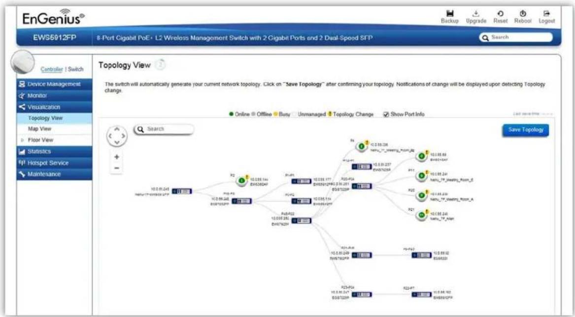
Topology View
From here, you can see a visual view of the topology of all supported devices in the network. The EWS Switch automacally maps your network deployment and displays the device relationships across your network infrastructure. An essenal feature for troublesomeong network issues that would otherwise require manual mapping, overlay monitoring soware, or manually keeping track of MAC address tables.
Use the direconal pad and the plus or minus buons to navigate your view of the network. You can also search Access Points in the network via their IP or MAC address. Check the Show Port Info box to show whether you wish the search query to show port informaon.
flowchart
graph TD
    A["10.0.01.24P"] --> B["10.0.05.24P"]
    B --> C["10.0.06.24P"]
    C --> D["10.0.07.24P"]
    D --> E["10.0.08.24P"]
    E --> F["10.0.09.24P"]
    F --> G["10.0.10.24P"]
    G --> H["10.0.11.24P"]
    H --> I["10.0.12.24P"]
    I --> J["10.0.13.24P"]
    J --> K["10.0.14.24P"]
    K --> L["10.0.15.24P"]
    L --> M["10.0.16.24P"]
    M --> N["10.0.17.24P"]
    N --> O["10.0.18.24P"]
    O --> P["10.0.19.24P"]
    P --> Q["10.0.20.24P"]
    Q --> R["10.0.21.24P"]
    R --> S["10.0.22.24P"]
    S --> T["10.0.23.24P"]
    T --> U["10.0.24.24P"]
    U --> V["10.0.25.24P"]
    V --> W["10.0.26.24P"]
    W --> X["10.0.27.24P"]
    X --> Y["10.0.28.24P"]
    Y --> Z["10.0.29.24P"]
    Z --> AA["10.0.30.24P"]
    AA --> AB["10.0.31.24P"]
    AB --> AC["10.0.32.24P"]
    AC --> AD["10.0.33.24P"]
    AD --> AE["10.0.34.24P"]
    AE --> AF["10.0.35.24P"]
    AF --> AG["10.0.36.24P"]
    AG --> AH["10.0.37.24P"]
    AH --> AI["10.0.38.24P"]
    AI --> AJ["10.0.39.24P"]
    AJ --> AK["10.0.40.24P"]
    AK --> AL["10.0.41.24P"]
    AL --> AM["10.0.42.24P"]
    AM --> AN["10.0.43.24P"]
    AN --> AO["10.0.44.24P"]
    AO --> AP["10.0.45.24P"]
    AP --> AQ["10.0.46.24P"]
    AQ --> AR["10.0.47.24P"]
    AR --> AS["10.0.48.24P"]
    AS --> AT["10.0.49.24P"]
    AT --> AU["10.0.50.24P"]
    AU --> AV["10.0.51.24P"]
    AV --> AW["10.0.52.24P"]
    AW --> AX["10.0.53.24P"]
    AX --> AY["10.0.54.24P"]
    AY --> AZ["10.0.55.24P"]
    AZ --> BA["10.0.56.24P"]
    BA --> BB["10.0.57.24P"]
    BB --> BC["10.0.58.24P"]
    BC --> BD["10.0.59.24P"]
    BD --> BE["10.0.60.24P"]
    BE --> BF["10.0.61.24P"]
    BF --> BG["10.0.62.24P"]
    BG --> BH["10.0.63.24P"]
    BH --> BI["10.0.64.24P"]
    BI --> BJ["10.0.65.24P"]
    BJ --> BK["10.0.66.24P"]
    BK --> BL["10.0.67.24P"]
    BL --> BM["10.0.68.24P"]
    BM --> BN["10.0.69.24P"]
    BN --> BO["10.0.70.24P"]
    BO --> BP["10.0.71.24P"]
    BP --> BQ["10.0.72-24P"]
    BQ --> BR[10-SPBPO 8-Port Pin 8-Port Pin 8-Port Pin 8-Port Pin 8-Port Pin 8-Port Pin 8-Port Pin 8-Port Pin 8-Port Pin 8-Port Pin 8-Port Pin 8-Port Pin 8-Port Pin 8-Port Pin 8-Port Pin 8-Port Pin 8-Port Pin 8-Port Pin 8-Port Pin 8-Port Pin 8-Port Pins 8-Port Pins 8-Port Pins 8-Port Pins 8-Port Pins 8-Port Pins 8-Port Pins 8-Port Pins 8-Port Pins 8-Port Pins 8-Port Pins 8-Port Pins 8-Port Pins 8-Port Pins 8-Port Pins 8-Port Pins 8-Port Pins 8-Port Pins 8-Port Pins 8-Port Pins 8-Port Pin 8-Port Pin 8-Port Pin 8-Port Pin 8-Port Pin 8-Port Pin 8-Port Pin 8-Port Pin 8-Port Pin 8-Port Pin 8-Port Pin 8-Port Pin 8-Port Pin 8-Port Pin 8-Port Pin 8-Port Pin 8-Port Pin 8-Port Pin 8-Port Pin 8-Port pin 8-Port pin 8-Port pin 8-Port pin 8-Port pin 8-Port pin 8-Port pin 8-Port pin 8-Port pin 8-Port pin 8-Port pin 8-Port pin 8-Port pin 8-Port pin 8-Port pin 8-Port pin 8-Port pin 8-Port pin 8-Port pin 8-Port pin 8-Port pins 8-Port pins 8-Port pins 8-Port pins 8-Port pins 8-Port pins 8-Port pins 8-Port pins 8-Port pins 8-Port pins 8-Port pins 8-Port pins 8-Port pins 8-Port pins 8-Port pins 8-Port pins 8-Port pins 8-Port pins 8-Port pins 8-Port pins 8-Port pin 8-Port pin 8-Port pin 8-Port pin 8-Port pin 8-Port pin 8-Port pin 8-Port pin 8-Port pin 8-Port pin 8-Port pin 8-Port pin 8-Port pin 8-Port pin 8-Port pin 8-Port pin 8-Port pin 8-Port pin 8-Port pin 8-Port Pin 8-Port Pin 8-Port Pin 8-Port Pin 8-Port Pin 8-Port Pin 8-Port Pin 8-Port Pin 8-Port Pin 8-Port Pin 8-Port Pin 8-Port Pin 8-Port Pin 8-Port Pin 8-Port Pin 8- port pin
| AP Status | Descripon |
| Online | The managed AP is currently online |
| Oine | The managed AP is currently oine |
| Busy | The managed AP is currently busy (applying new conguraon sengs) |
| Unmanaged | The AP is not managed by the controller |
| Topology Change | There is a change in topology for this device |
Navigang Tips
Use to scroll up, down, le, or right.
Use to Zoom in/out. Alternatively, you can use the mouse to navigate by clicking and dragging the le mouse buon. Use the mouse wheel to zoom in/out.
Mouse over a device to show informaon about the device.

Le click on the Switch bring up a menu where you can redirect to switch or collapse topology tree.

Le click on the Access Point to bring up a menu where you can congure AP sengs, remove AP from management list, reboot AP, redirect to the Acve Clients page or redirect to troublesomeong page.

Search
You can search for an Access Point using the IP Address or MAC address.
Click on ☑ to show or hide port informaon on the Controller.
Click on for the Controller to save the current network topology. Changes will be displayed upon detecting a topology change.
Note: The EWS Switch can only generate topologies with EnGenius L2 Series switches. Non-EnGenius switches will be marked as “Uncontrollable LAN Switches” in the generated topology.
Map View
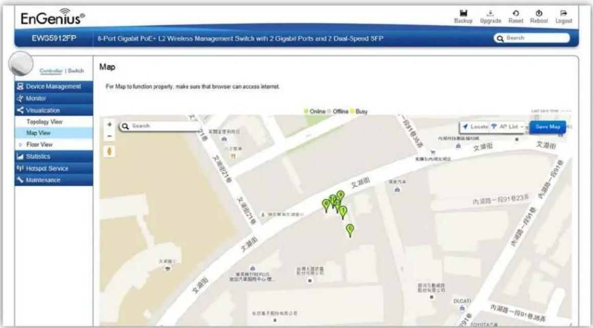
From here, you can view a geographical representation of Access Points in the network. Click AP List to display the list of Access Points managed by the EWS switch then simply click-and-drag the AP marker to the desired location on the map.
Note: Your browser needs to be able to access the Internet for this funcon to work.
| AP Status | Descripon |
| Online | The managed AP is currently online |
| Oine | The managed AP is currently oine |
| Busy | The managed AP is currently busy (applying new conguraon sengs) |
Navigang Tips
Use to scroll up, down, le, or right.
Use the slider bar to Zoom in/out. Alternatively, you can use the mouse to navigate by clicking and dragging the le mouse buon. Use the mouse wheel to zoom in/out.
Search
Use the Search box to search for locaons by typing an address or the name of a landmark.
Use the Locate button to pinpoint the map to your current locaon. Note that the locaon provided is calculated based on your IP address and results might be inaccurate.

Le click on the Access Point marker to bring up a menu where you can congregate AP sengs, remove AP from management list, reboot AP, redirect to the Acve Clients page or redirect to troublesomeong page.
Click on for the sengs to take eect.
Floor View
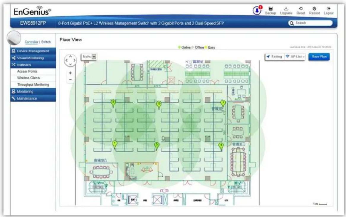
The Floor View feature enables an administrator to upload custom oor plans and place AP markers in relevant locaons for beer network visualizaon of a wireless network. Mulple images can be uploaded to visualize Access Point placement on mulple oors of an oce building or dierent branch oces within an organizaon.
Floorplan Image
From here, an administrator can add or delete a custom map or oor plan image. An unlimited number of oor plan images can be imported to the EWS Switch. However, the total
le size of all imported oor plans is limited to 6MB and the maximum le size per image is 512KB (a smaller image loads faster). Valid image le formats are .PNG, .GIF or .JPG.

Status Dashboard
Total: Displays the total memory storage space allocated for uploading custom oor plans.
Available: Display the memory storage space that is currently available.
In Use: Displays the memory storage space that is currently in use.
Use the Edit Buon to edit the Name/Descripon of the imported image.

Delete Buon
Use the Delete Buon to remove the image.

Floorplan View
Aer imporng your oor plan image, you can distribute markers that represent the APs to the correct locaons by clicking on AP List and dragging each marker icon to its correct locaon on the oor plan.
Also, Wireless Coverage Display can be toggled on to indicate the coverage range of each AP, assisting IT managers to easily and accurately plan and deploy wireless networks in any indoor environment. Click on Save Plan when you're done to save sengs.
Sengs

Setting
radar
| Metric | Value | | -------------------- | ----- | | AP Information | -68 | | 2.4GHz | -65 | | 5GHz | -62 | | Scaling Tool | -59 | | RF Coverage | Enable | | RSSI Value | -65 | | Calibration Offset | -5 | | RSSI Range Simulate | 3 |AP Info
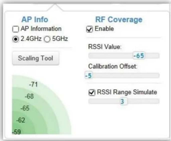
AP Informaon: Select to toggle on/o AP detailed informaon to be shown on your oor plan.
2.4GHz / 5GHz: Select whether to display signal coverage of 2.4GHz or 5GHz radio. The wireless coverage displayed will be based on the transmit power sengs of the Access Point.
Scaling Tool: Use the scaling tool to determine the exact distance on the oorplan.
Signal Indicator: The colored indicator displays the reference signal strength covered.
RF Coverage
Enable: Select to display wireless coverage on your oor plan.
RSSI Value: Adjust RSSI value to emulate using the slider bar.
Calibraon Oset: Use the slider bar to adjust the oset value based on the deployment.
RSSI Range Simulate: Check the RSSI Simulate box to display RSSI reference on your oor plan. Adjust RSSI coverage range to emulate using the slider bar.
Navigang Tips
Use to scroll up, down, le, or right.
Use to Zoom in/out. Alternatively, you can use the mouse to navigate by clicking and dragging the le mouse buon. Use the mouse wheel to zoom in/out.
Mouse over a device to show informaon about the device.
AP List: Click to reveal a list of APs that the EWS Switch is currently managing.
The number in the marker represents the number of wireless clients that are currently connected to the Access Point.

Le click on the Access Point marker to bring up a menu where you can congregate AP sengs, remove AP from management list, reboot AP, redirect to the Acve Clients page or redirect to troublesome page.
Click on Save Plan for the sengs to take eect.
Statistics
Access Points
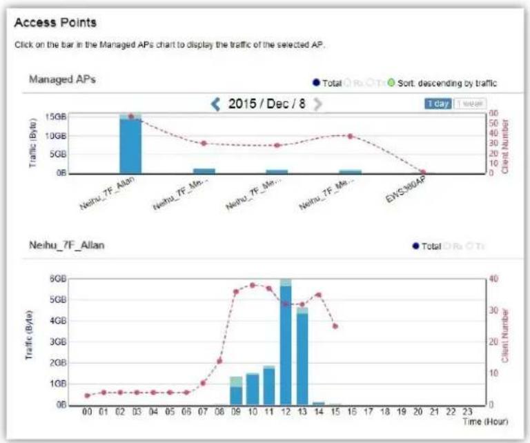
The page displays a visual chart of the network trac of all the Access Points managed by the EWS Switch.
bar_line
Access Points Click on the bar in the Managed APs chart to display the traffic of the selected AP. | Time (Hour) | Total (Rs OTi) | Sort. descending by traffic (Client Number) | |---|---|---| | 00 | 0 | 5 | | 01 | 0 | 6 | | 02 | 0 | 6 | | 03 | 14.5 | 58 | | 04 | 0 | 6 | | 05 | 0 | 6 | | 06 | 0 | 6 | | 07 | 0 | 10 | | 08 | 0 | 18 | | 09 | 0 | 56 | | 10 | 0 | 58 | | 11 | 0 | 54 | | 12 | 0 | 58 | | 13 | 0 | 44 | | 14 | 0 | 2 | | 15 | 0 | 1 | | 16 | 0 | 0 | | 17 | 0 | 0 | | 18 | 0 | 0 | | 19 | 0 | 0 | | 20 | 0 | 0 | | 21 | 0 | 0 | | 22 | 0 | 0 | | 23 | 0 | 0 | | Neihu_7F_Allan | Total (Rs OTi) | | :--- | :--- | | 00: | 0 | | 01: | 0 | | 02: | 0 | | 03: | 14.5 | | 04: | 0 | | 05: | 0 | | 06: | 0 | | 07: | 0 | | 08: | 0 | | 09: | 1.5 | | 10: | 1.5 | | 11: | 1.8 | | 12: | 6.2 | | 13: | 4.5 | | 14: | 1.2 | | 15: | 0.3 | | 16: | 0.3 | | 17: | 0.3 | | 18: | 0.3 | | 19: | 0.3 | | 20: | 0.3 | | 21: | 0.3 | | 22: | 0.3 | | 23: | 0.3 |Navigang Tips
Click Sort to sort the order from ascending/descending, depending on your preference.
Click Rx to display Rx transmission, Tx to display Tx transmission or Total to display combined Rx and Tx transmission.
Click 1 day or 1 week buon to select a me increment to monitor stascs by.
Place the mouse cursor over the bar on the chart to show detailed informaon.
Click on the bar in the Managed APs chart to display the trac of the selected AP.
Wireless Clients
In addition to viewing informaon based on speci Access Points, you can view data via speci clients as well for security purposes.
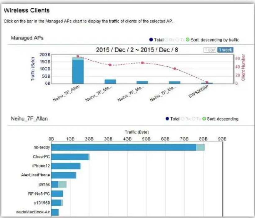
bar_line
Wireless Clients Click on the bar in the Managed APs chart to display the traffic of clients of the selected AP. | Client | Total Traffic (Byte) | Sort: descending by traffic | | :--- | :--- | :--- | | Neihu_7F_Alan | 1800000000000000 | 50 | | Neihu_7F_Ma... | 350000000000000 | 45 | | Neihu_7F_Ma... | 250000000000000 | 45 | | Neihu_7F_Ma... | 250000000000000 | 45 | | EWS36OAP | 5000000000000 | 1 | NEihu_7F_Alan Total Traffic (Byte) Total OR OTx Sort: descending by traffic nb-teddy Chou-PC iPhone12 AlexLinsiPhone james RF-No5-PC s101560 mudeMacBook-AirNavigang Tips
Click Sort to sort the order from ascending/descending, depending on your preference.
Click Rx to display Rx transmission, Tx to display Tx transmission or Total to display combined Rx and Tx transmission.
Click 1 day or 1 week buon to select a me increment to monitor stascs by.
Place the mouse cursor over the bar on the chart to show detailed informaon.
Click on the bar in the Managed APs chart to display the wireless clients that has associated with the selected AP.
Real Time Throughput
This page displays the real-me network activity of the selected Access Point.

line
| Time (s) | Throughput (Byte/sec) | | -------- | --------------------- | | 120 | 100K | | 100 | 500KB | | 80 | 450KB | | 60 | 450KB | | 40 | 450KB | | 20 | 400KB | | 0 | 350KB |Hotspot Services
A hotspot is a wireless network that provides access through a capve portal. Use this feature to setup capve portal related conguraons.
A capve portal provides registered users with network access while containing unregistered users. Users will need to enter a valid user name and password before they are allowed access to the Internet through the hotspot. Once a Capve Portal Prole is created, the administrator can apply this prole to mulple Guest Networks SSIDs.
Note: Capve portal proles can only be assigned to the Guest Network SSIDs.
Captive Portal

Login Type: Denes the mechanism by which a wireless client gains access to the network aer the client has associated to the SSID.
| Splash & Go | The wireless client is granted network access without any further authencaon as soon as it is associates to the SSID. |
| Local User DB | The wireless client is authenticated using the EWS Switch's local database (from Hotspot Service > Guest Account). |
| External RADIUS Server | The wireless client is authenticated using an external RADIUS server. |
Login Page: A splash page is the web page which prompts the user to log in with a user name and password, or accept a network use policy once the client has associated to the SSID.
| Local Web Page | Use the splash page hosted locally by EWS Switch. The local splash page enable administrators to eliminate the need to set up a local web server. Basic customizaons like displaying a corporate logo, custom message and term of use is available. |
| Redirect users to external URL | External splash page enables the administrator to host their own the splash page web server, rather than having it hosted by the EWS Switch. |
Redirect Behavior: Congure where users will be redirected aer successful login. You could redirect them to the page that they want to visit, or you could set a dierent page where users will be redirected.
| Redirect to the URL that the user was trying to visit | Select this opon for ezMaster to cache the initial website from the client during the authencaon process and then forward it to the originally targeted web server aer the user successfully authencates. |
| Redirect users to a specied URL aer login | Select this opon to redirect users to a specic URL aer users successfully authencates. |
User Session: Congure session meout and ideal meout period.
| Session Timeout | Specify a me limit aer which users will be disconnected and required to log in again. |
| Idle Timeout | Specify a me limit for an idle client aer which users will be disconnected and required to log in again. |
Walled Garden: This opon allows users to dene network desnaons that users can access before authencaon. For example, your company's website.
Guest Account
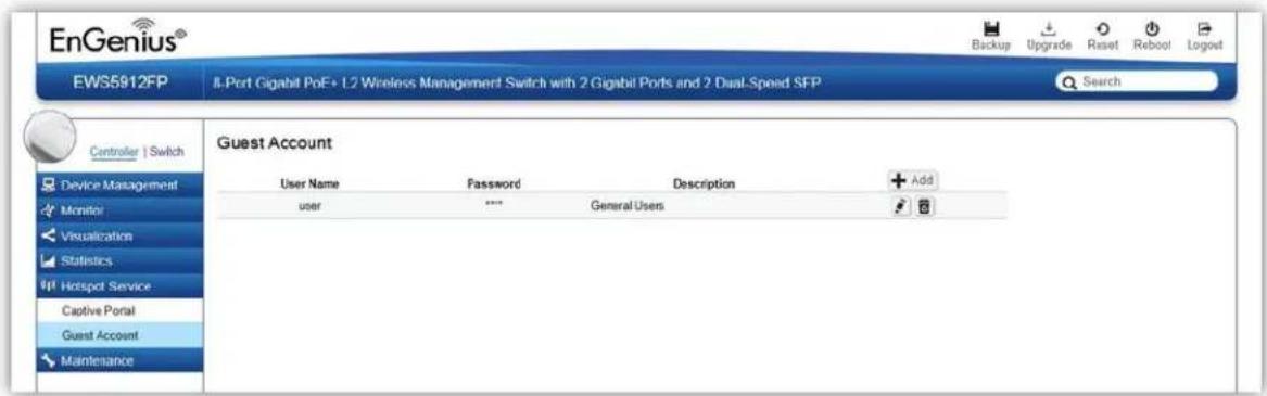
On this page, an administrator can create, edit, and remove user accounts used for capve portal's local database authencaon.
Add: Create a new user account.
Remove: Delete the selected user account.
Edit: Edit the sengs of the selected user account.
Maintenance
Schedule Tasks

Use the Schedule Tasks feature to control the me(s), or day(s) of a week, or date of a month to automacally perform the following task:
Reboot AP(s): So reboot AP
Change WLAN State: Enable/disable WLAN service
Change Switch PoE State: By port PoE enable or disable. Only available for PoE supported models.
Switch PoE Reset: Power cycle PoE port. Only available for PoE supported models.
NOTE: This feature will not work properly if the EWS Switch does not have the correct me setngs.
Troubleshooting
From here, you can troubleshoot any issues you have with Access Points connected to the network. This feature is designed primarily for administrators to verify and test the link route between the Switch and the Access Point. A troublesome soluon is provided by the system so that administrators can know where the problem lies. Note that the topology of the network needs to be saved for this funcon to work properly.
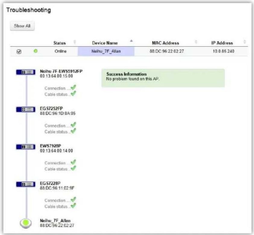
Choosing an Access Point to Diagnose
A list will show the current status of Access Points on the network. Select an Access Point to begin a diagnosc test. If mulple Access Points are connected, use the search bar to the top right of the page to nd the Access Point you wish to troubleshoot. The controller will run a diagnosc test for the selected Access Point. Click Start to run the test. The test take a few seconds to complete. Aerwards, the results will display on the page.
Bulk Upgrade
The Bulk Upgrade feature allows administrators to upgrade the rmware of multiple Access Points at the same me. Aer uploading the rmware of an AP, the system will automatically display a list of Access Points the system is currently managing that the uploaded rmware is for.

To upgrade, please follow the steps below:
- Click on Upload New File to mount AP rmware onto EWS Switch ash
- Once the Access Point rmware is uploaded onto the Controller, the list of Access Points that the uploaded rmware is for will appear in the Device List.
- Select the Access Points you wish to upgrade and click Add to Upgrade to start the rmware upgrading process.
NOTE: Upgrading APs will temporarily disconnect them (and any associated clients) from the network. To minimize network disrupon, we recommend performing the rmware upgrading procedure at an o-peak me.
One-Click Update
The EWS Switch can be congured to automacally check for new rmware updates for your EWS devices. The icon below will appear on the upper right corner of the user interface when a new update is available. Simply click on the icon and follow the on screen instrucons to update your devices.

Note: An acve Internet conncon is required for this feature.
Update List
This page displays the devices which has new rmware updates available. A release note states the purpose of the rmware. Click on Check for Updates for the EWS Switch to check for the latest rmware. Select the devices you wish to update and click on Update buon to begin the updang process.
Note: Both the EWS Switch and the browser on the PC must be able to access the Internet for this funcon to work. One Click Update might also not be available if you are using a proxy server for Internet conneccons.
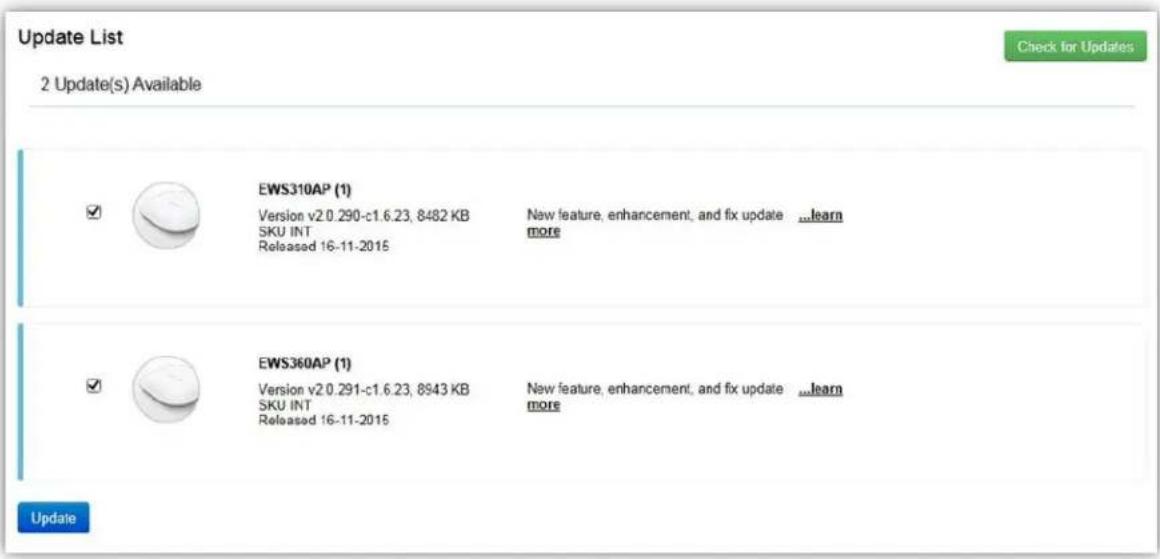
Update Settings
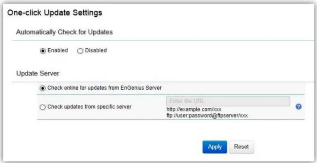
Automacally Check for Updates
Enable/disable automacally check for new updates for your devices.
Update Server
Choose whether you wish to check for updates from EnGenius server or specify your own hp/p server path.
Check updates from specific server
Apart from copying rmware image les into the specic hp/p path, an index le is required in the same folder.
Follow the instrucons below for creang the index le.
- Create a new .txt le with the name "laswlist.txt".
- In the le, create entries based on the format below and save the le.
| Field | Descripon | Reference String |
| Model Name | Enter model name. | EWS310AP, EWS320AP, EWS660AP |
| Firmware Version | Enter rmware version. | v2.0.129-c1.3.5 |
| File Name | Enter complete lename with extension. | ews310ap-fcc-v2.0.132.0-c1.3.5.bin |
| MD5 | Enter MD5 value of the rmware image | 4959e8d68536227d182b53a719dcdae4 |
| SKU | Enter in device SKU. | FCC, ETSI, INT |
Example:
EWS210AP,v2.0.129-c1.3.5,ews210ap-fcc-v2.0.129.0-c1.3.5.bin,af44f429a5404e2f7bde651921366c33,FCC
EWS210AP,v2.0.129-c1.3.5,ews210ap-etsi-v2.0.129.0-c1.3.5.bin,186cab281b7038e7c9b8909acfd9e63e,ETSI
EWS310AP,v2.0.132-c1.3.5,ews310ap-fcc-v2.0.132.0-c1.3.5.bin,4959e8d68536227d182b53a719dcdae4,FCC
EWS310AP,v2.0.132-c1.3.5,ews310ap-etsi-v2.0.132.0-c1.3.5.bin,0ee6663cc9b6c652b1139214455ed92e,ETSI
EWS320AP,v2.0.132-c1.3.5,ews320ap-fcc-v2.0.132.0-c1.3.5.bin,e584a03d0218a0f1a29a4c5550c99614,FCC
EWS320AP,v2.0.132-c1.3.5,ews320ap-etsi-v2.0.132.0-c1.3.5.bin,967312acc588b6caad7e55a98fc19997,ETSI
EWS360AP,v2.0.130-c1.3.5,ews360ap-fcc-v2.0.130.0-c1.3.5.bin,3b8f450f171c0f839032124cbe4860,FCC
EWS360AP,v2.0.130-c1.3.5,ews360ap-etsi-v2.0.130.0-c1.3.5.bin,e2483bfc74259263dda18e8d86682183,ETSI
EWS660AP,v2.0.124-c1.3.5,ews660ap-int-v2.0.124.0-c1.3.5.bin,cc00b2871dec668b9a1b82f330a2611e,FCC
EWS660AP,v2.0.124-c1.3.5,ews660ap-etsi-v2.0.124.0-c1.3.5.bin,d67554b30fd98d06093f7da306cb8fd2,ETSI
EWS860AP,v2.0.124-c1.3.5,ews860ap-fcc-v2.0.124.0-c1.3.5.bin,39f5f935f7b83515c4a6c30ef4c61114,FCC
SSL Certificate
SSL cercates enables device or user idencaon, as well as secure communicaons. Administrators can create a self-signed SSL Cercate to secure communicaons between the Switch and Access Points. Note that Access Points will disconnect and reconnect using new cercate upon applying changes.

Enter the informaon below to generate a request for an SSL cercate for the controller.
| Common Name | Enter the name of the request. |
| Organizaon | Enter the organizaons name. |
| Organizaon Unit | Enter a unit name (department, etc.). |
| Locality/City | Enter the locality or city. |
| State/Province | Enter the state or province. |
| Country | Enter the name of the country. |
| Valid Date | Enter the expiry date of the cercate. |
Click on Restore buon under Advance Opons to restore the default SSL Cercate sengs.
Check Codes
Use this feature to generate a list of 'Check Codes' for the APs that your EWS Switch is current managing. Check Codes are used for registering devices to ezMaster.
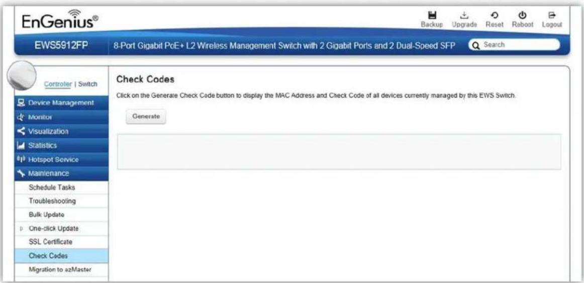
Migration to ezMaster
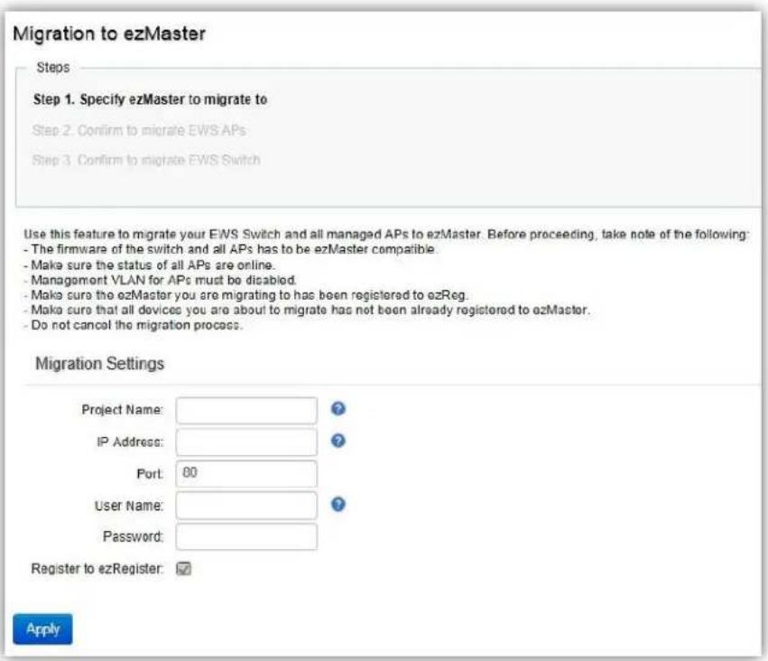
This feature will help to migrate the EWS Switch and all the APs managed by the EWS Switch to ezMaster automacally without the need of manually entering the check code and MAC address of all the APs one by one.
Take note of the following before proceeding with the migraon process:
- The rmware of the switch and all APs has to be ezMaster compatible.
• Make sure the status of all APs are online. - Management VLAN for APs must be disabled.
• Make sure the ezMaster you are migrang to has been registered to ezReg.
• Make sure that all devices you are about to migrate has not been already registered to ezMaster. - Do not cancel the migraon process.
Ethernet Switch Features
System
Summary
The Summary page shows general system informaon for the Switch including the device name, the soware version, serial number, MAC address, IP Address, gateway address, and system upme.
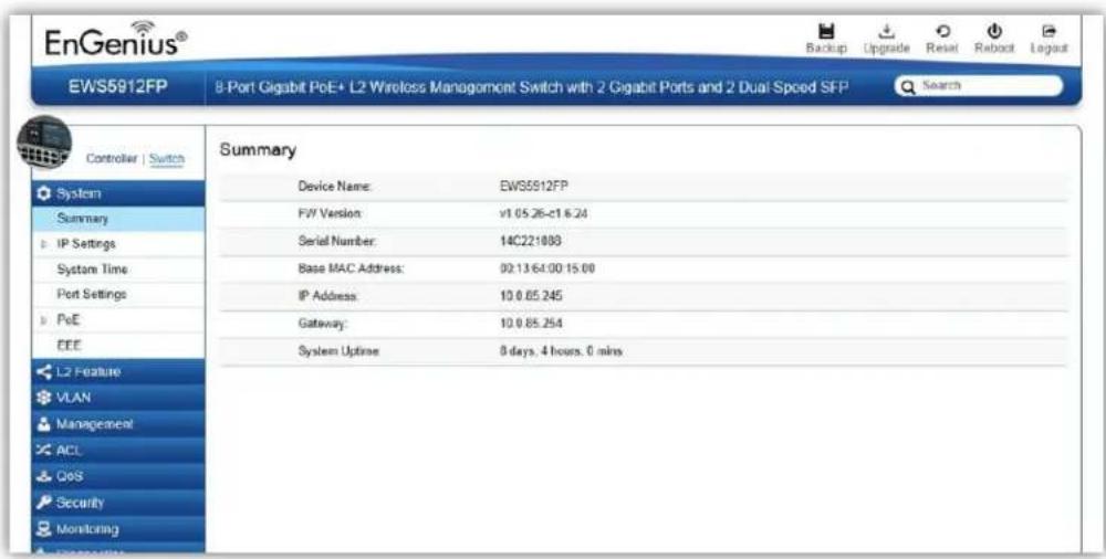
| Device Name | Displays the model name of the device. |
| FW Version | Displays the installed rmware version of the device. |
| Serial Number | Displays the serial number of the device. |
| Base MAC Address | Displays the MAC address of the device. |
| IP Address | Displays the IP address of the device. |
| Gateway | Displays the Gateway IP address. |
| System Upme | Displays the number of days, hours, and minutes since the last system restart. The System Upme is displayed in the following format: days, hours, and minutes. |
IP Settings
The IP Seng screen contains elds for assigning IP addresses. IP addresses are either dened as stac or are retrieved using the Dynamic Host Conguraon Protocol (DHCP). DHCP assigns dynamic IP addresses to devices on a network. DHCP ensures that network devices can have a dierent IP address every me the device connects to the network.
To access the page, click IP Sengs under the System menu.
IPv4
Select whether to you wish to enable Stac or DHCP for auto-conguraon. Next, enter the informaon for the IP address, gateway, and DNS servers.


Important:
If the device fails to retrieve an IP address through DHCP, the default IP address is 192.168.0.239 and the factory default subnet mask is 255.255.255.0.
| Dynamic IP Address (DHCP) | Enables the IP address to be congured automacally by the DHCP server. Select this opon if you have a DHCP server that can assign the Switch an IP address, subnet mask, default gateway IP address, and a domain name server IP address automacally. Selecng this eld disables the IP Address, Subnet Mask, and Gateway elds. |
| Stac IP Address | Allows the entry of an IP address, subnet mask, and a default gateway forthe Switch. Select this opon if you don't have a DHCP server or if you wish to assign a stac IP address to the Switch. |
| IP Address | This eld allows the entry of an IPv4 address to be assigned to this IP interface. Enter the IP address of your Switch in doed decimal notaon.The factory default value is: 192.168.0.239 |
| Subnet Mask | A subnet mask separates the IP address into the network and host addresses. A bitmask that determines the extent of the subnet that the Switch is on. This should be labeled in the form: xxx.xxx.xxx.xxx, where each xxx is a number (represented in decimals) between 0 and 255. The value should be 255.0.0.0 for a Class A network, 255.255.0.0 for a Class B network, and 255.255.255.0 for a Class C network, but custom subnet masks are allowed. Enter the IP subnet mask of your Switch in doed decimal notaon. The factory default value is: 255.255.255.0 |
| Gateway | Enter an IP address that determines where packets with a desnaon address outside the current subnet should be sent. This is usually the address of a router or a host acng as an IP gateway your network is not part of an Intranet, or you do not want the Switch to be accessible outside your local network, you can leave this eld blank. |
| DNS Server (Domain Name System) | Used for mapping a domain name to its corresponding IP addresses and vice versa. Enter a DNS IP address in order to be able to use a domain name to access the Switch instead of using an IP address. |
Click Apply to save sengs.
IPv6
IPv6 is an upgraded version to IPv4, providing more available IP addresses as well as other benets. To access the switch over an IPv6 network you must rst congure it with IPv6 informaon (IPv6 prex, prex length, and default gateway). To congure IPv6 for the Switch, select whether to you wish to enable Auto-Conguraon, Stac, or DHCPv6 Client. Next, enter the informaon for the IP address, range, and gateway.

| IPv6 State | Select whether you wish to enable Auto Conguraon, DHCPv6 Client, or Stac for the IPv6 address. |
| Auto Conguraon | Use this opon to set the IPv6 address for the IPv6 network interface in Auto Conguraon. The Switch will automacally generate and use a globally-unique IPv6 address based on the network prex and its Ethernet MAC address. |
| DHCPv6 Client | This enables the IP address to be congured automacally by the DHCP server. Select this opon if you have an IPv6 DHCP server that can assign the Switch an IPv6 address/prex and a default gateway IP address. |
| Stac | Allows the entry of an IPv6 address/prex and a default gateway for the Switch. Select this opon if you wish to assign stac IPv6 address informaon to the Switch. |
| IPv6 Address | This eld allows the entry of an IPv6 address/prex to be assigned to this IP interface. |
| Gateway | Set the default gateway IPv6 address for the interface. Enter the default gateway IPv6 address. |
Click Apply to save sengs.
System Time
Use the System Time screen to view and adjust date and me sengs.
The Switch supports Simple Network Time Protocol (SNTP). SNTP assures accurate network device clock me synchronizaon up to the millisecond. Time synchronizaon is performed by a network SNTP server. This switch operates only as an SNTP client and cannot provide me services to other systems.
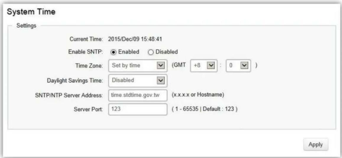
| Current me | Displays the current system me. |
| Enable SNTP | Select whether to enable or disable system me synchronizaon with an SNTP server. |
| Time Zone | Congure the me zone seng either by seng GMT dierence or by country. |
| Daylight Savings Time | Select from Disabled, Recurring or Non-recurring. |
| Daylight Savings Time Oset | Enter the me of Daylight Savings Time Oset. |
| Recurring From | Select the Day, Week, Month, and Hour from the list. |
| Recurring To | Select the Day, Week, Month, and Hour from the list. |
| SNTP/NTP Server Address | Enter the IP address or hostname of the SNTP/NTP server. |
| Server Port | Enter the server port of the SNTP/NTP server. |
To congure date/me through SNMP:
- Next to the Enable SNTP, select Enable.
- In the Time Zone Oset list, select by country or by the GMT me zone in which the Switch is located.
- Next select Disabled, Recurring, or Non-Recurring for Daylight Savings Time. Daylight saving is a period from late spring to early fall when many countries set their clocks ahead of normal local me by one hour to give more dayme light in the evening.
- In the SNTP/NTP Server Address eld, enter the IP address or the host name of the SNTP/NTP server.
- Finally, enter the port number on the SNTP server to which SNTP requests are sent. The valid range is from 1–65535. The default is: 123.
- Click Apply to update the system sengs.
To congure date/me manually:
- Next to the Enable SNTP, select Disable.
- In the Manual Time eld, use the drop-down boxes to manually select the date and me you wish to set.
- In the Time Zone Oset list, select by country or by the Coordinated Universal Time (UTC/GMT) me zone in which the Switch is located.
- Next select Disabled, Recurring or Non-recurring for Daylight Savings Time. Daylight saving is a period from late spring to early fall when many countries set their clocks ahead of normal local me by one hour to give more dayme light in the evening.
- Click Apply to update the system sengs.
Port Settings
Use this screen to view and congure Switch port sengs. The Port Sengs page allows you change the conguraon of the ports on the Switch in order to nd the best balance of speed and ow control according to your preferences. Conguring Gigabit ports require additional factors to be considered when arranging your preferences for the Switch compared to 10/100 ports.
To access the page, click Port Sengs under the System menu.
| Port Settings | ||||
| Port | Link Status | Mode | Flow Control | |
| ☐ | Auto | Disabled | ||
| ☐ | 1 | Link Down | Auto | Disabled |
| ☐ | 2 | Link Down | Auto | Disabled |
| ☐ | 3 | Link Down | Auto | Disabled |
| ☐ | 4 | Link Down | Auto | Disabled |
| ☐ | 5 | Link Down | Auto | Disabled |
| ☐ | 6 | Link Down | Auto | Disabled |
| ☐ | 7 | Link Up | Auto-1000M/Full | Disabled |
| ☐ | 8 | Link Up | Auto-1000M/Full | Disabled |
| ☐ | 9 | Link Up | Auto-1000M/Full | Disabled |
| ☐ | 10 | Link Up | Auto-1000M/Full | Disabled |
| ☐ | 11 | Link Down | Auto | Disabled |
| ☐ | 12 | Link Down | Auto | Disabled |
| ☐ | trunk1 | Link Down | Auto | Disabled |
| ☐ | trunk2 | Link Down | Auto | Disabled |
| ☐ | trunk3 | Link Down | Auto | Disabled |
| ☐ | trunk4 | Link Down | Auto | Disabled |
| ☐ | trunk5 | Link Down | Auto | Disabled |
| ☐ | trunk6 | Link Down | Auto | Disabled |
| Port | Displays the port number. |
| Link Status | Indicates whether the link is up or down. |
| Mode | Select the speed and the duplex mode of the Ethernet conncon on this port.Selecng Auto (auto-negoaon) allows one port to negate with a peer portautomacally to obtain the conncon speed and duplex mode that both ends support. When auto-negoaon is turned on, a port on the Switch negoates with the peer automacally to determine the conncon speed and duplex mode.If the peer port does not support auto-negoaon or turns o this feature, theSwitch determines the conncon speed by detectng the signal on the cable and using half duplex mode. When the Switch's auto-negoaon is turned o, a portuses the pre-congured speed and duplex mode when making a conncon, thus requiring you to make sure that the sengs of the peer port are the same in order to connect. |
| Flow Control | A concentraon of trac on a port decreases port bandwidth and overows buer memory causing packet discards and frame losses. Flow Control is used to regulate transmission of signals to match the bandwidth of the receiving port. The Switch uses IEEE 802.3x ow control in full duplex mode and backpressure ow control in half duplex mode.IEEE 802.3x ow control is used in full duplex mode to send a pause signal to the sending port, causing it to temporarily stop sending signals when the receiving port memory buers II.Back Pressure ow control is typically used in half duplex mode to send a "collision" signal to the sending port (mimicking a state of packet collision) causing the sending port to temporarily stop sending signals and resend later. |
Click Apply to save sengs.
PoE
The PoE Management screen contains system PoE informaon for monitoring the current power usage and assigns the total amount of power the Switch can provide to all of its PoE ports. To access the page, click PoE under the System menu.
Note: This feature is only available for PoE supported models listed below.
| Model | PoE Capable Ports | PoE Standard | PoE Power Budget |
| EWS2910P | 8 | IEEE 802.3af | 61.6 Was |
| EWS5912FP | 8 | IEEE 802.3af/at | 130 Was |
| EWS7928P | 24 | IEEE 802.3af/at | 185 Was |
| EWS7928FP | 24 | IEEE 802.3af/at | 370 Was |
| EWS7952FP | 48 | IEEE 802.3af/at | 740 Was |
Power Budget
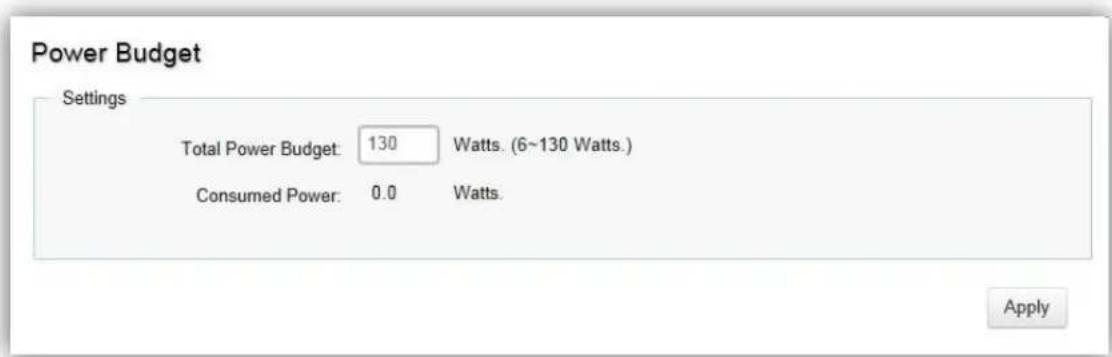
Total Power Budget: Enter the amount of power the Switch can provide to all ports.
Consumed Power: Displays the total amount of power (in was) currently being delivered to all PoE ports.
PoE Port Settings

| Port | Displays the specic port for which PoE parameters are dened. PoE parameters are assigned to the powered device that is connected to the selected port. |
| State | Displays the acve parcipang members of the trunk group. |
| Member Port | Enable: Enables the Device Discovery protocol and provides power to the device using the PoE module. The Device Discovery protocol lets the device discover powered devices aached to device interfaces and learns their classicaon.Disable: Disables the Device Discovery protocol and halts the power supply delivering power to the device using the PoE module. |
| Priority | Select the port priority if the power supply is low. The eld default is Low. For example, if the power supply is running at 99% usage, and port 1 is prioritized as high, but port 6 is prioritized as low, port 1 is prioritized to receive power and port 6 may be denied power.Low: Sets the PoE priority level as low.Medium: Sets the PoE priority level as medium.High: Sets the PoE priority level as high.Crical: Sets the PoE priority level as crical. |
| Class (Auto) | Shows the classicaon of the powered device. The class denes the maximum power that can be provided to the powered device. The possible eld values are:Class 0: The maximum power level at the Power Sourcing Equipment is 15.4 Was.Class 1: The maximum power level at the Power Sourcing Equipment is 4.0 Was.Class 2: The maximum power level at the Power Sourcing Equipment is 7.0 Was.Class 3: The maximum power level at the Power Sourcing Equipment is 15.4 Was.Class 4: The maximum power level at the Power Sourcing Equipment is 30 Was. |
| Class (User Dened) | Select this opon to base the power limit on the value congured in the User Power Limit eld. |
| User Power Limit | Set the maximum amount of power that can be delivered by a port.Note: The User Power Limit can only be implemented when the Class value is set to User-Dened. |
| Status | Shows the port's PoE status. The possible eld values are:Delivering Power: The device is enabled to deliver power via the port.Disabled: The device is disabled for delivering power via the port.Test Fail: The powered device test has failed. For example, a port could not be enabled and cannot be used to deliver power to the powered device.Tesng: The powered device is being tested. For example, a powered device is tested to conrm it is receiving power from the power supply.Searching: The device is currently searching for a powered device. Searching is the default PoE operaonal status.Fault: The device has detected a fault on the powered device when the port is forced on. For example, the power supply voltage is out of range, a short occurs, a communicaon or there is a communicaon error with PoE devices, or an unknown error occurs. |
Click Apply to save sengs.
EEE
Energy Ecient Ethernet (EEE), an Institute of Electrical and Electronics Engineers (IEEE) 802.3az standard, reduces the power consumption of physical layer devices during periods of low link ulizaon. EEE saves energy by allowing PHY non-essential circuits shut down when there is no trac.
Network administrators have long focused on the energy eciency of their infrastructure, and the EnGenius Layer 2 Switch complies with the IEEE's Energy-Ecient Ethernet (EEE) standard. The EEE compliant Switch oers users the ability to ulize power that Ethernet links use only during data transmission. Lower Power Idle (LPI) is the method for achieving the power saving during Ethernet ideal me.
Use the EEE conguraon page to conjure Energy Ecient Ethernet.
| Energy-Efficient Ethernet | ||
| Port | EEE Status | |
| ☐ | Disabled ☑ | |
| ☐ | 1 | Disabled |
| ☐ | 2 | Disabled |
| ☐ | 3 | Disabled |
| ☐ | 4 | Disabled |
| ☐ | 5 | Disabled |
| ☐ | 6 | Disabled |
| ☐ | 7 | Disabled |
| ☐ | 8 | Disabled |
| ☐ | 9 | Disabled |
| ☐ | 10 | Disabled |
| Port | Display the port for which the EEE seng is displayed. |
| EEE Status | Enable or disable EEE for the specied port. |
Click Apply to save sengs.
L2 Feature
The L2 Feature tab exhibits complete standard-based Layer 2 switching capabilities, including: Link Aggregaon, 802.1D Spanning Tree Protocol, 802.1w Rapid Spanning Tree Protocol, 802.1s Mulple Spanning Tree Protocol, MAC Address Table, Internet Group Management Protocol (IGMP) Snooping, Port Mirroring, 802.1ab Link Layer Discovery Protocol (LLDP), and Mulcast Listener Discovery (MLD) snooping. Ulyze these features to congure the Switch to your preferences.
Link Aggregation
A Link Aggregaon Group (LAG) optimizes port usage by linking a group of ports together to form a single, logical, higher-bandwidth link. Aggregang ports mulplies the bandwidth and increases port exibility for the Switch. Link Aggregaon is most commonly used to link a bandwidth intensive network device (or devices), such as a server, to the backbone of a network.
The parcipang ports are called Members of a port trunk group. Since all ports of the trunk group must be congured to operate in the same manner, the conguraon of the one port of the trunk group is applied to all ports of the trunk group. Thus, you will only need to conjure one of any of the ports in a trunk group. A specific data communicaon packet will always be transmied over the same port in a trunk group. This ensures the delivery of individual frames of a data communicaon packet will be received in the correct order. The trac load of the LAG will be balanced among the ports according to Aggregate Arithmec. If the conncons of one or several ports are broken, the trac of these ports will be transmied on the normal ports, so as to guarantee the conncon reliability.
When you aggregate ports, the ports and LAG must full the following conditions:
All ports within a LAG must be the same media/format type.
A VLAN is not congured on the port.
The port is not assigned to another LAG.
The Auto-negoaon mode is not congured on the port.
The port is in full-duplex mode.
All ports in the LAG have the same ingress ltering and tagged modes.
All ports in the LAG have the same back pressure and flow control modes.
All ports in the LAG have the same priority.
All ports in the LAG have the same transceiver type.
Ports can be congured as LACP ports only if the ports are not part of a previously congured LAG.
LACP is a dynamic protocol which helps to automate the conguraon and maintenance of LAG's. The main purpose of LACP is to automacally congregate individual links to an aggregate bundle, while adding new links and helping to recover from link failures if the need arises. LACP can monitor to verify if all the links are connected to the authorized group. LACP is a standard in computer networking, hence LACP should be enabled on the Switch's trunk ports initially in order for both the parcipang Switches/devices that support the standard, to use it.
Port Trunking
Port Trunking allows you to assign physical links to one logical link that funcons as a single, higher-speed link, providing dramacally increased bandwidth. Use Port Trunking to bundle mulple connexons and use the combined bandwidth as if it were a single larger "pipe".

Important:
You must enable Trunk Mode before you can add a port to a trunk group.
| Group | Active Ports | Member Ports | Mode | |
| 1 | Disabled | |||
| 2 | Disabled | |||
| 3 | Disabled | |||
| 4 | Disabled | |||
| 5 | Disabled | |||
| 6 | Disabled | |||
| 7 | Disabled | |||
| 8 | Disabled |
| Group | Displays the number of the given trunk group. You can ulize up to 8 link aggregaon groups and each group consisng up to 8 ports on the Switch. |
| Acve Ports | Displays the acve parcipang members of the trunk group. |
| Member Port | Select the ports you wish to add into the trunk group. Up to eight ports per group can be assigned.Stac: The Link Aggregaon is congured manually for specied trunk group.LACP: The Link Aggregaon is congured dynamically for specied trunk group. |
| Mode | LACP allows for the automac detecon of links in a port trunking group when connected to a LACP-compliant Switch. You will need to ensure that both the Switch and device connected to are in the same mode in order for them to funcon, otherwise they will not work. Stac conguraon is used when connecng to a Switch that does not support LACP. |
Click the Apply button √ to accept the changes or the Cancel button ✗ to discard them.
LACP Settings
Assign a system priority to run with Link Aggregaon Control Protocol (LACP) and is become for a backup link if a link goes down. The lowest system priority is allowed to make decisions about which ports it is acvely parcipang in in case a link goes down. If two or more ports have the same LACP port priority, the port with the lowest physical port number will be selected as the backup port. If a LAG already exists with the maximum number of allowed port members, and LACP is subsequently enabled on another port using a higher priority than an exisng member, the newly congured port will replace the exisng port member that has a lower priority. A smaller number indicates a higher priority level. The range is from 0-65535 and default is: 32768.

| System Priority | Enter the LACP priority value to the system. The default is 32768 and the range is from 1 to 65535. |
Click Apply to save sengs.
LACP Timeout
Link Aggregaon Control Protocol (LACP) allows the exchange of informaon with regard to the link aggregaon between two members of aggregaon. The LACP Time Out value is measured in a periodic interval. Check rst whether the port in the trunk group is up. When the interval expires, it will be removed from the trunk. Set a Short Timeout (one second) for busy trunked links to ensure that disabled ports are removed from the trunk group as soon as possible. The default value for LACP me out is: Long Timeout.
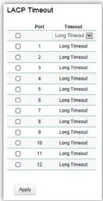
| Timeout | Select the administrave LACP meout.Long Timeout:The LACP PDU will be sent for every 30 seconds, and the LACP meout value is 90 seconds.Short Timeout:The LACP PDU will be sent every second. The meout value is 3 seconds. |
Click Apply to save sengs.
Mirror Settings
Mirrors network trac by forwarding copies of incoming and outgoing packets from specific ports to a monitoring port. The packet that is copied to the monitoring port will be the same format as the original packet.
Port mirroring is useful for network monitoring and can be used as a diagnosc tool. Use port mirroring to send trac to applicaons that analyze trac for purposes such as monitoring compliance, detectcng intrusions, monitoring and predicng trac paerns, and other correlang events. Port Mirroring is needed for trac analysis on a Switch because a Switch normally sends packets only to the port to which the desnaon device is connected. The analyzer captures and evaluates the data without aecng the client on the original port. Port mirroring can consume significant CPU resources while acve, so be cauous of such usage when conguring the Switch.
| Session ID | Destination Port | Source TX Port | Source RX Port | Ingress State | Session State |
| 1 | 1 | Disabled | Disabled | ||
| 2 | N/A | Disabled | Disabled | ||
| 3 | N/A | Disabled | Disabled | ||
| 4 | N/A | Disabled | Disabled |
| Session ID | A number identifying the mirror session. This Switch only supports up to 4 mirror sessions. |
| Desnaon Port | Select the port for trac purposes from source ports mirrored to this port. |
| Source TX/RX Port | Sets the source port from which trac will be mirrored.TX Port: Only frames transmied from this port are mirrored to the desnaon port.RX Port: Only frames received on this port are mirrored to the desnaon port.Both: Frames received and transmied on this port are mirrored to the specied desnaon port.None: Disables mirroring for this port. |
| Ingress State | Select whether to enable or disable ingress trac forwarding. |
| Session State | Select whether to enable or disable port mirroring. |

Note
You cannot mirror a faster port onto a slower port. For example, if you try to mirror the trac from a 100Mbps port onto a 10Mbps port, this can cause throughput problems. The port you are copying frames from should always support an equal or lower speed than the port to which you are sending the copies. Please note a target port and a source port cannot be the same port.
Click the Apply button √ to accept the changes or the Cancel buon ✗ to discard them.
STP
The Spanning Tree Algorithm (STA) can be used to detect and disable network loops, and to provide backup links between Switches. This allows the Switch to interact with other bridging devices in your network to ensure that only one route exists between any two staons on the network, and provide backup links which automacally take over when a primary link goes down.
STP provides a tree topology for the Switch. There are different types of Spanning tree versions, supported, including Spanning Tree Protocol (STP) IEEE 802.1D, Mulple Spanning Tree Protocol (MSTP) IEEE 802.1w, and Rapid Spanning Tree Protocol (RSTP) IEEE 802.1s. Please note that only one spanning tree can be acute on the Switch at a me.
Global Settings
Spanning Tree Protocol (STP) is a Layer 2 protocol that runs on Switches. Spanning Tree Protocol (STP) allows you to ensure that you do not create loops when you have redundant paths in the network. STP provides a single acve path between two devices on a network in order to prevent loops from being formed when the Switch is interconnected via mulple paths.
STP uses a distributed algorithm to select a bridging device that serves as the root for the spanning tree network. It does this by selecng a root port on each bridging device to incur the lowest path cost when forwarding a packet from that device to the root device. It then selects a designated bridging device from each LAN which incurs the lowest path cost when forwarding a packet from that LAN to the root device. Next, all ports connected to designated bridging devices are assigned as designated ports. Aer determining the lowest cost spanning tree, it enables all root ports and designated ports, disabling all other ports. Network packets are therefore only forwarded between root ports and designated ports, eliminang any possible network loops. STP provides a single acve path between two devices on a network in order to prevent loops from being formed when the Switch is interconnected via mulple paths.
Once a stable network topology has been established, all bridges listen for Hello Bridge Protocol Data Units (BPDUs) transmied from the Root Bridge of the Spanning Tree. If a bridge does not receive a Hello BPDU aer a predened interval (known as the Maximum Age), the bridge will assume that the link to the Root Bridge is down and unavailable. This bridge then initiates negoans with other bridges to reconfigure the network to reestablish a valid network topology.
Loops occur when alternate routes exist between hosts. Loops in an extended network can cause the Switch to forward trac indenitely, resulting in increased trac and reducing network eciency. Once the STP is enabled and congured, primary links are established and duplicated links are blocked automacally. The reacvaon of the blocked links is also accomplished automacally.
STP provides a tree topology and other Spanning tree versions supported include STP, Mulple Spanning Tree Protocol (MSTP), and Rapid Spanning Tree Protocol (RSTP). Please note that only one spanning tree can be acve on the Switch at a me. The default seng is: RSTP.

| STP | Select whether to enable or disable the spanning tree operaon on the Switch. |
| Force Version | Select the Force Protocol Version parameter for the Switch.STP (Spanning Tree Protocol): IEEE 802.1DRSTP (Rapid Spanning Tree Protocol): IEEE 802.1wMSTP (Mulple Spanning Tree Protocol): IEEE 802.1s |
Mulple Spanning Tree Protocol (MSTP) dened in IEEE 802.1s, enables mulple VLANs to be mapped to reduce the number of spanning-tree instances needed to support a large number of VLANs. If there is only one VLAN in the network, a single STP works appropriately.
If the network contains more than one VLAN however, the logical network congured by a single STP would work, but it becomes more efficient to use the alternate paths available by using an alternate spanning tree for different VLANs or groups of VLANs. MSTP (which is based on RSTP for fast convergence) is designed to support independent spanning trees based on VLAN groups. MSTP provides multiple forwarding paths for data trac and enables load balancing.
STP and RSTP prevent loops from forming by ensuring that only one path exists between the end nodes in your network. RSTP is designed as a general replacement for the slower, legacy STP. RSTP is also incorporated into MSTP. With STP, convergence can take up to a minute to complete in a larger network.
This can result in the loss of communicaon between various parts of the network during the convergence process so STP can subsequently lose data packets during transmission.
RSTP on the other hand is much faster than STP. It can complete a convergence in seconds, so it greatly diminishes the possible impact the process can have on your network compared to STP. RSTP reduces the number of state changes before acve ports start learning, predening an alternate route that can be used when a node or port fails and retain the forwarding database for ports insensitive to changes in the tree structure when reconguraon occurs.
Select whether to Enable or Disable the Spanning Tree funcon for the Switch. Next, select whether you wish to enable STP, RSTP, or MSTP. Again, please note that only one Spanning tree funcon can be acute at a me.
Click Apply to save sengs.
Root Bridge
The Root Bridge serves as an administrave point for all Spanning Tree calculaons to determine which redundant links to block in order to prevent network loops. From here, you can view all the informaon regarding the Root Bridge within the STP.
All other decisions in a spanning tree network, such as ports being blocked and ports being put in a forwarding mode, are made regarding a root bridge. The root bridge is the “root” of the constructed “tree” within a spanning tree network. Thus, the root bridge is the bridge with the lowest bridge ID in the spanning tree network. The bridge ID includes two parts; the bridge priority (2 bytes) and the bridge MAC address (6 bytes). The 802.1d default bridge priority is: 32768. STP devices exchange Bridge Protocol Data Units (BPDUs) periodically. All bridges “listen” for Hello BPDUs (Bridge Protocol Data Units) transmied from the root bridge. If a bridge does not get a Hello BPDU aer a predened interval (called the Maximum Age), the bridge assumes that the link to the root bridge is down. The bridge then initiates negoans with other bridges to recongure the network to re-establish a valid network topology.
Root Bridge
| Root Address: | 00:02:6F:AA:AA:AB |
| Priority: | 32768 |
| Cost: | 60000 |
| Port: | 10 |
| Forward Delay: | 15 (sec) |
| Maximum Age: | 20 (sec) |
| Hello Time: | 2 (sec) |
| Root Address | Displays the root bridge MAC address. Root in root bridge refers to the base of the spanning tree, which the Switch could be congured for. |
| Priority | Displays the priority for the bridge. When switches are running STP, each is assigned a priority. Aer exchanging BPDUs, the Switch with the lowest priority value becomes the root bridge. |
| Forward Delay | Displays the Switch Forward Delay Time. This is the me (in seconds) the root switch will wait before changing states (called listening to learning). |
| Maximum Age | Displays the bridge Switch Maximum Age Time. This is the amount of me a bridge waits before sending a conguraon message. The default is 20 seconds. |
| Hello Time | Displays the Switch Hello Time. This is the amount of me a bridge remains in a listening and learning state before forwarding packets. The default is 15 seconds. |
CIST Instance Settings
The Common Instance Spanning Tree (CIST) protocol is formed by the spanning tree algorithm running among bridges that support the IEEE 802.1w, IEEE 802.1s, and IEEE 802.1D standard. A Common and Internal Spanning Tree (CIST) represents the connectivity of the enre network and it is equivalent to a spanning tree in an STP/RSTP.
The CIST inside a Mulple Spanning Tree Instance (MST) region is the same as the CST outside a region. All regions are bound together using a CIST, which is responsible for creang loop-free topology across regions, whereas the MSTI controls topology inside regions. CST instances allow dierent regions to communicate between themselves. CST is also used for trac within the region for any VLANs not covered by a MSTI. In an MSTP-enabled network, there is only one CIST that runs between MST regions and single spanning tree devices. A network may contain mulple MST regions and other network segments running RSTP. Mulple regions and other STP bridges are interconnected using a single CST.
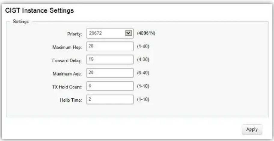
Enter the informaon to set up CIST for the Switch:
| Root Address | Displays the root bridge MAC address. Root in root bridge refers to the base of the spanning tree, which the Switch could be congured for. |
| Priority | Displays the priority for the bridge. When switches are running STP, each is assigned a priority. Aer exchanging BPDUs, the Switch with the lowest priority value becomes the root bridge. |
| Forward Delay | Displays the Switch Forward Delay Time. This is the me (in seconds) the rootswitch will wait before changing states (called listening to learning). |
| Maximum Age | Displays the bridge Switch Maximum Age Time. This is the amount of me a bridge waits before sending a conguraon message. The default is 20 seconds. |
| Hello Time | Displays the Switch Hello Time. This is the amount of me a bridge remains in a listening and learning state before forwarding packets. The default is 15 seconds. |
Click Apply to update the system sengs.
CIST Port Settings
Use the CIST Ports Sengs page to congregate and view STA aributes for interfaces when the spanning tree mode is set to STP or RSTP. You may use a different priority or path cost for ports of the same media type to indicate a preferred path or edge port to indicate if the aached device can support fast forwarding or link type to indicate a point-to-point conncon or shared-media conncon.
| Port | Priority | InternalPathCost/Oper | ExternalPath CostConf /Oper | PathCost | Designated RootBridge | ExternalRootCost | Regioned RootBridge | InternalRootCost | Designated Bridge | EdgePortCost /Oper | P2P MACCost /Oper | Port Role | Port State | MigrationStart | |
| 120 | In-As | Yes ☑ | Yes ☑ | ☐ | |||||||||||
| 1 | 128 | 0 / 20000 | 0 / 20000 | 20000 | 3 / 0 /00:00 00:00:00 | 0 | 9 / 0 /00:00 00:00:00 | 0 | 0 / 0 /00:00 00:00:00 | Yes / - | Auto / - | Disabled | Disabled | - | |
| 2 | 128 | 0 / 20000 | 0 / 20000 | 20000 | 3 / 0 /00:05 05:52:05:65 | 300000 | 26672 / 0 /00:13:64 00:15:00 | 0 | 26672 / 0 /00:13:64 00:15:00 | Yes / Yes | Auto / Yes | Designated | Forwarding | - | |
| 3 | 128 | 0 / 20000 | 0 / 20000 | 20000 | 3 / 0 /00:00 00:00:00 | 0 | 9 / 0 /00:00 00:00:00 | 0 | 0 / 0 /00:00 00:00:00 | Yes / - | Auto /- | Disabled | Disabled | - | |
| 4 | 128 | 0 / 20000 | 0 / 20000 | 20000 | 3 / 0 /00:00 00:00:00 | 0 | 9 / 0 /00:00 00:00:00 | 0 | 0 / 0 /00:00 00:00:00 | Yes / - | Auto /-- | Disabled | Disabled | - | |
| 5 | 128 | 0 / 20000 | 0 / 20000 | 20000 | 3 / 0 /00:00 00:00:00 | 0 | 9 / 0 /00:00 00:00:00 | 0 | 0 / 0 /00:00 00:00:00 | Yes / - | Auto / -- | Disabled | Disabled | - | |
| 6 | 128 | 0 / 20000 | 0 / 20000 | 20000 | 3 / 0 /00:00 00:00:00 | 0 | 9 / 0 /00:00 00:00:00 | 0 | 0 / 0 /00:00 00:00:00 | Yes / - | Auto /--- | Disabled | Disabled | - | |
| 7 | 128 | 0 / 20000 | 0 / 20000 | 20000 | 3 / 0 /00:05 05:52:05:65 | 300000 | 26672 / 0 /00:13:64 00:15:00 | 0 | 26672 / 0 /00.13:64 00:15:00 | Yes / Yes | Auto / Yes | Designated | Forwarding | - | |
| 8 | 128 | 0 / 20000 | 0 / 20000 | 20000 | 3 / 0 /00:05 05:52:05:65 | 300000 | 26672 / 0 /00:13:64 00:15:00 | 0 | 26672 / 0 /00 :13:64 00:15:00 | Yes / Yes | Auto / Yes | Designated | Forwarding | - | |
| 9 | 128 | 0 / 20000 | 0 / 20000 | 20000 | 3 / 0 /00:05 05:52:05:65 | 300000 | 26672 / 0 /00:13:64 00:15:00 | 0 | 26672 / 0 /00 .13:64 00:15:00 | Yes / Yes | Auto / Yes | Designated | Forwarding | - | |
| 10 | 128 | 0 / 20000 | 0 / 20000 | 20000 | 3 / 0 /00:05 05:52:05:65 | 200000 | 32768 / 0 /88 DC 96 1D 0A:05 | 0 | 12768 / 0 /88 DC 96 1D 0A:05 | Yes / No | Auto / Yes | Root | Forwarding | - | |
| 11 | 128 | 0 / 20000 | 0 / 20000 | 20000 | 3 / 0 /00:00 00:00:00 | 0 | 9 / 0 /00:00 00:00:00 | 0 | 0 / 0 /00:00 00:00:00 | Yes / - | Auto/- | Disabled | Disabled | - | |
| 12 | 128 | 0 / 20000 | 0 / 20000 | 20000 | 3 / 0 /00:00 00:00:00 | 0 | 9 / 0 /00:00 00:00:00 | 0 | 0 / 0 /00:00 00:00:00 | Yes / - | Auto/-/- | Disabled | Disabled | - | |
| truck1 | 128 | 0 / 20000 | 0 / 20000 | 20000 | 3 / 0 /00:00 00:00:00 | 0 | 9 / 0 /00:00 00:00:00 | 0 | 0 / 0 /00:00 00:00:00 | Yes / - | Auto/ - | Disabled | Disabled | - | |
| truck2 | 128 | 0 / 20000 | 0 / 20000 | 20000 | 3 / 0 /00:00 00:00:00 | 0 | 9 / 0 /00:00 00:00:00 | 0 | 0 / 0 /00:00 00:00:00 | Yes / - | Auto/ -- | Disabled | Disabled | - | |
| truck3 | 128 | 0 / 20000 | 0 / 20000 | 20000 | 3 / 0 /00:00 00:00:00 | 0 | 9 / 0 /00:00 00:00:00 | 0 | 0 / 0 /00:00 00:00:00 | Yes / - | Auto/--- | Disabled | Disabled | - | |
| truck4 | 128 | 0 / 20000 | 0 / 20000 | 20000 | 3 / 0 /00:00 00:00:00 | 0 | 9 / 0 /00:00 00:00:00 | 0 | 0 / 0 /00:00 00:00:00 | Yes / - | Auto/-- | Disabled | Disabled | - | |
| truck5 | 128 | 0 / 20000 | 0 / 20000 | 20000 | 3 / 0 /00:00 00:00:00 | 0 | 9 / 0 /00:00 00:00:00 | 0 | 0 / 0 /00:00 00:00:00 | Yes / - | Auto/---- | Disabled | Disabled | - |
| MST ID | Select the MST ID from the list. |
| Port | Port or trunked port idener. |
| Priority | Denes the priority used for this port in the Spanning Tree Algorithm. If the path cost for all ports on a Switch are the same, the port with the highest priority (i.e., lowest value) will be congured as an acve link in theSpanning Tree. This makes a port with higher priority less likely to be blocked if the Spanning Tree Algorithm is detectcng network loops. When more than one port is assigned the highest priority, the port with lowest numeric idener will be enabled. The range is from 0 to 240, in steps of 16; and the default is: 128. |
| Internal Path Cost Conf/Oper | The Internal Path Cost seng allows you to specify the relave cost of sending spanning tree trac through the interface to adjacent bridges within a spanning tree region. |
| External Path Cost Conf/Oper | The External Path Cost seng is used to calculate the cost of sending spanning tree trac through the interface to reach an adjacent spanning tree region. The spanning tree algorithm tries to minimize the total path cost between each point of the tree and the root bridge. |
| Designated Root Bridge | Displays the root bridge for the CST. It is comprised using the bridge priority and the base MAC address of the bridge. |
| Internal Root Cost | This is the cost to the CIST regional root in a region. |
| External Root Cost | External root cost is the cost to the CIST root. |
| Regional Root Bridge | This is the bridge idener of the CST regional root. It is made up using the bridge priority and the base MAC address of the bridge. |
| Internal Port Cost | Enter the cost of the port. |
| Edge Port Conf/Oper | Displays the edge port state. |
| Designated Bridge | This is the bridge idener of the bridge of the designated port. It is made up using the bridge priority and the base MAC address of the bridge. |
| Port Role | Each MST bridge port that is enabled is assigned a port role within each spanning tree. The port role will be one of the following values: Root Port, Designated Port, Alternate Port, Backup Port, Master Port, or Disabled. |
| Port State | The forwarding state of this port. The state parameters are: Discarding, Learning, Forwarding, or Disabled. |
Click Apply to update the system sengs.
MST Instance Settings
Mulple Spanning Tree Protocol, or MSTP enables the grouping of mulple VLANs with the same topology requirements into one Mulple Spanning Tree Instance (MSTI). MSTP then builds an Internal Spanning Tree (IST) for the region containing commonly congured MSTP bridges. Instances are not supported in STP or RSTP. Instead, they have the same spanning tree in common within the VLAN. MSTP provides the capability to logically divide a Layer 2 network into regions. Every region can contain mulple instances of spanning trees. In MSTP, all of the interconnected bridges that have the same MSTP conguraon comprise an MST region.
A Common Spanning Tree (CST) interconnects all adjacent MST regions and acts as a virtual bridge node for communicaons between STP or RSTP nodes in the global network. MSTP connects all bridges and LAN segments with a single Common and Internal Spanning Tree (CIST). The CIST is formed as a result of the running spanning tree algorithm between switches that support STP, RSTP, and MSTP protocols. Once you specify the VLANs you wish to include in a Mulple Spanning Tree Instance (MSTI), the protocol will automatically build an MSTI tree to maintain connectivity among each of the VLANs. MSTP maintains contact with the global network because each instance is treated as an RSTP node in the Common Spanning Tree (CST).
Click the Edit buon to conjure the MST sengs. Next, enter informaon for the VLAN List and choose the priority you wish to use from the drop down list.
MST Instance Settings
| MST ID | VLAN List | Priority | Regional Root Bridge | Internal Root Cost | Designated Bridge | Root Port | |
| 1 | 32768 | --/- | 0 | --/- | -- | ||
| 2 | 32768 | --/- | 0 | --/- | -- | ||
| 3 | 32768 | --/- | 0 | --/- | -- | ||
| 4 | 32768 | --/- | 0 | --/- | -- | ||
| 5 | 32768 | --/- | 0 | --/- | -- | ||
| 6 | 32768 | --/- | 0 | --/- | -- | ||
| 7 | 32768 | --/- | 0 | --/- | -- | ||
| 8 | 32768 | --/- | 0 | --/- | -- | ||
| 9 | 32768 | --/- | 0 | --/- | -- | ||
| 10 | 32768 | --/- | 0 | --/- | -- | ||
| 11 | 32768 | --/- | 0 | --/- | -- | ||
| 12 | 32768 | --/- | 0 | --/- | -- | ||
| 13 | 32768 | --/- | 0 | --/- | -- | ||
| 14 | 32768 | --/- | 0 | --/- | -- | ||
| 15 | 32768 | --/- | 0 | --/- | -- |
| MST ID | Displays the ID of the MST group that is created. A maximum of 15 groups can be set for the Switch. |
| VLAN List | Enter the VLAN ID range from for the congured VLANs to associate with the MST ID. The VLAN ID number range is from 1 to 4094. |
| Priority | Select the bridge priority value for the MST. When Switches or bridges are running STP, each is assigned a priority. Aer exchanging BPDUs, the Switch with the lowest priority value becomes the root bridge. The default value is: 32768. The range is from 0 to 61440. The bridge priority is a mulple of 4096. |
| Regional Root Bridge | This is the bridge idener of the CST regional root. It is made up using the bridge priority and the base MAC address of the bridge. |
| Internal Root Cost | Displays the path cost to the designated root for the MST instance. |
| Designated Bridge | Displays the bridge idener of the bridge with the designated port. It is made up using the bridge priority and the base MAC address of the bridge. |
| Root Port | Displays the port that accesses the designated root for MST instance. |
Click the Apply button

to accept the changes or the Cancel buon

to discard them.
MST Port Settings
This page displays the current MSTI conguraon informaon for the Switch. From here you can update the port conguraon for an MSTI ID. If a loop occurs, the MSTP funcon will use the port priority to select an interface to put into the forwarding state. Set a higher priority value for ports you wish to be selected for forwarding rst. In instances where the priority value is identical, the MSTP funcon will implement the lowest MAC address into the forwarding state and other interfaces will be blocked. Note that a lower priority values mean higher priorities for forwarding packets.
| MST Port Settings | |||||||||
| MST ID | Port | Priority | Internal Path Cost Conf / Oper | Regional Root Bridge | Internal Root Cost | Designated Bridge | Port Role | Port State | |
| □ | 1 | √ | 128 | 0 | |||||
| □ | 1 | 1 | 128 | 0/20000 | -/- | -- | -/- | -- | -- |
| □ | 1 | 2 | 128 | 0/20000 | -/- | -- | -/- | -- | -- |
| □ | 1 | 3 | 128 | 0/20000 | -/- | -- | -/- | -- | -- |
| □ | 1 | 4 | 128 | 0/20000 | -/- | -- | -/- | -- | -- |
| □ | 1 | 5 | 128 | 0/20000 | -/- | -- | -/- | -- | -- |
| □ | 1 | 6 | 128 | 0/20000 | -/- | -- | -/- | -- | -- |
| □ | 1 | 7 | 128 | 0/20000 | -/- | -- | -/- | -- | -- |
| □ | 1 | 8 | 128 | 0/20000 | -/- | -- | -/- | -- | -- |
| □ | 1 | 9 | 128 | 0/20000 | -/- | -- | -/- | -- | -- |
| □ | 1 | 10 | 128 | 0/20000 | -/- | -- | -/- | -- | -- |
| □ | 1 | 11 | 128 | 0/20000 | -/- | -- | -/- | -- | -- |
| □ | 1 | 12 | 128 | 0/20000 | -/- | -- | -/- | -- | -- |
| □ | 1 | trunk1 | 128 | 0/20000 | -/- | -- | -/- | -- | -- |
| □ | 1 | trunk2 | 128 | 0/20000 | -/- | -- | -/- | -- | -- |
| □ | 1 | trunk3 | 128 | 0/20000 | -/- | -- | -/- | -- | -- |
| □ | 1 | trunk4 | 128 | 0/20000 | -/- | -- | -/- | -- | -- |
| □ | 1 | trunk5 | 128 | 0/20000 | -/- | -- | -/- | -- | -- |
| □ | 1 | trunk6 | 128 | 0/20000 | -/- | -- | -/- | -- | -- |
| □ | 1 | trunk7 | 128 | 0/20000 | -/- | -- | -/- | -- | -- |
| □ | 1 | trunk8 | 128 | 0/20000 | -/- | -- | -/- | -- | -- |
| MST ID | Displays the ID of the MST group that is created. A maximum of 15 groups can be set for the Switch. |
| Port | Displays port or trunked port ID. |
| Priority | Select the bridge priority value for the MST. When switches or bridges are running STP, each is assigned a priority. Aer exchanging BPDUs, the Switch with the lowest priority value becomes the root bridge. The bridge priority is a mulple of 4096. If you specify a priority that is not a mulple of 4096, the priority is automacally set to the next lowest priority that is a mulple of 4096. For example, if you set the priority to any value from 0 through 4095, the priority is set to 0. The default priority is: 32768. The valid range is from 0 to 61440. |
| Internal Path Cost Conf | The Internal Path Cost seng allows you to specify the relave cost of sending spanning tree trac through the interface to adjacent bridges within a spanning tree region. |
| Internal Path Cost Oper | Displays the operaon cost of the path from this bridge to the root bridge. |
| Regional Root Bridge | This is the bridge idener of the CST regional root. It is made up using the bridge priority and the base MAC address of the bridge. |
| Internal Root Cost | Displays the path cost to the designated root for the selected MST instance. |
| Designated Bridge | Displays the bridge idener of the bridge for the designated port. It is made up using the bridge priority and the base MAC address of the bridge. |
| Internal Port Cost | This parameter is set to represent the relave cost of forwarding packets to specied ports when an interface is selected within an STP instance. Selecng this parameter with a value in the range of 1 to 200000000 will set the quickest route when a loop occurs. A lower internal cost represents a quicker transmission. Selecng 0 (zero) for this parameter will set the quickest opmal route automacally for an interface. |
| Port Role: | Each MST bridge port that is enabled is assigned a port role for each spanning tree. The port role is one of the following values: Root, Designated, Alternate, Backup, Master, or Disabled. |
| Port State | Displays the state of the selected port. |
| Edge Port Ope | Displays the operang edge port state. |
| P2P MAC Conf | Displays the P2P MAC state. |
| P2P MAC Oper | Displays the operang P2P MAC state. |
| Port Role | Displays the port role. Shows each MST bridge port that is assigned a port role for each spanning tree. |
| Port State | Indicates the current STP state of a port. If enabled, the port state determines what forwarding acon is taken regarding trac. The possible port states are:Disabled:STP is disabled on the port. The port forwards trac while learning MAC addresses.Blocking:The port is blocked and cannot be used to forward trac or learn MAC addresses.Listening:The port is in listening mode. The port cannot forward trac or learn MAC addresses in this state.Learning:The port is in learning mode. The port cannot forward trac. However, it can learn new MAC addresses.Forwarding:The port is in forwarding mode. The port can forward trac and learn new MAC addresses in this state. |
Click Apply to update the system sengs.
MAC Address Table
The MAC address table contains address informaon that the Switch uses to forward trac between the inbound and outbound ports. All MAC addresses in the address table are associated with one or more ports. When the Switch receives trac on a port, it searches the Ethernet switching table for the MAC address of the desnaon. If the MAC address is not found, the trac is ooded out all of the other ports associated with the VLAN. All of the MAC address that the Switch learns by monitoring trac are stored in the dynamic address. A stac address allows you to manually enter a MAC address to congregate a specific port and VLAN.
Static MAC Address
The address table lists the desnaon MAC address, the associated VLAN ID, and port number associated with the address. When you specify a stac MAC address, you set the MAC address to a VLAN and a port; thus it makes an entry into its forwarding table. These entries are then used to forward packets through the Switch. Stac MAC addresses along with the Switch's port security allow only devices in the MAC address table on a port to access the Switch.
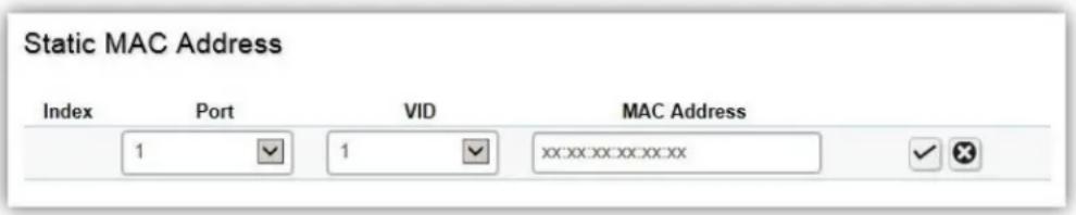
| Index | Displays the index for the stac MAC address table. |
| Port | Select the port where the MAC address entered in the previous eld will be automacally forwarded. |
| VID | Enter the VLAN ID on which the IGMP Snooping querier is administratively enabled and for which the VLAN exists in the VLAN database. |
| MAC Address | Enter a unicast MAC address for which the switch has forwarding or Itering informaon. |
Click the Apply button √ to accept the changes or the Cancel buon ✗ to discard them.
Dynamic MAC Address
The Switch will automatically learn the device's MAC address and store it to the dynamic MAC address table. If there is no packet received from the device within the aging me, the Switch adopts an aging mechanism for updang the tables from which MAC address entries will be removed from related network devices. The dynamic MAC address table shows the MAC addresses and their associated VLANs learned on the selected port.
| Dynamic MAC Address | ||
| MAC Address | VID | Port |
| 00:00:00:01:02:03 | 1 | 10 |
| 00:02:6F:FE:94:46 | 1 | 2 |
| 00:02:6F:FE:94:47 | 1 | 2 |
| 00:02:6F:FE:94:48 | 1 | 2 |
| 00:04:5F:8D:2D:24 | 1 | 10 |
| 00:07:11:04:42:0F | 1 | 9 |
| 00:08:9B:F1:8F:AE | 1 | 10 |
| 00:0C:29:00:85:D3 | 1 | 10 |
| 00:0C:29:07:ED:6A | 1 | 10 |
| 00:0C:29:0C:11:1D | 1 | 10 |
| Index | Displays the index for the dynamic MAC address table. |
| Port | Select the port to which the entry refers. |
| VID | Displays the VLAN ID corresponding to the MAC address. |
| MAC Address | Displays the MAC addresses that the Switch learned from a specic port. |
LLDP
Link Layer Discovery Protocol (LLDP) is the IEEE 802.1AB standard for Switches to adverse their identity, major capabilities, and neighbors on the 802 LAN. LLDP allows users to views the discovered informaon to identify system topology and detect faulty conguraons on the LAN. LLDP is essentially a neighbor discovery protocol that uses Ethernet connectivity to adverse informaon to devices on the same LAN and store informaon about the network. The informaon transmied in LLDP adversements ow in one direcon only; from one device to its neighbors. This informaon allows the device to quickly identify a variety of other devices, resulting in a LAN that interoperates smoothly and eciently.
LLDP transmits informaon as packets called LLDP Data Units (LLDPDUs). A single LLDPDU is transmied within a single 802.3 Ethernet frame. A basic LLDPDU consists of a set of Type-Length-Value elements (TLV), each of which contains informaon about the device. A single LLDPDU contains mulple TLVs. TLVs are short informaon elements that communicate complex data. Each TLV adverses a single type of informaon.
Global Settings

Select whether to enable or disable the LLDP feature on the Switch. Next, enter the Transmission Interval, Holdme Mulplier, Reinializaon Delay parameter, and the Transmit Delay parameter. When nished, click Apply to update the system sengs.
| State | Select Enabled or Disabled to acvate LLDP for the Switch. |
| Transmission Interval | Enter the interval at which LLDP adversement updates are sent. The default value is 30. The range is from 5 to 32768. |
| Holdme Mulplier | Enter the amount of me that LLDP packets are held before packets are discarded and measured in mulples of the Adversed Interval. The default is 4. The range is from 2 to 10. |
| Reinializaon Delay | Enter the amount of me of delay before reinializing LLDP. The default is 2. The range is from 1 to 10. |
| Transmit Delay | Enter the amount of me that passes between successive LLDP frame transmissions. The default is 2 seconds. The range is from 1 to 8191 seconds. |
Local Device
LLDP devices must support chassis and port ID adversement, as well as the system name, system ID, system descripon, and system capability adversements. Here, you can view detailed LLDP informaon for the Switch.
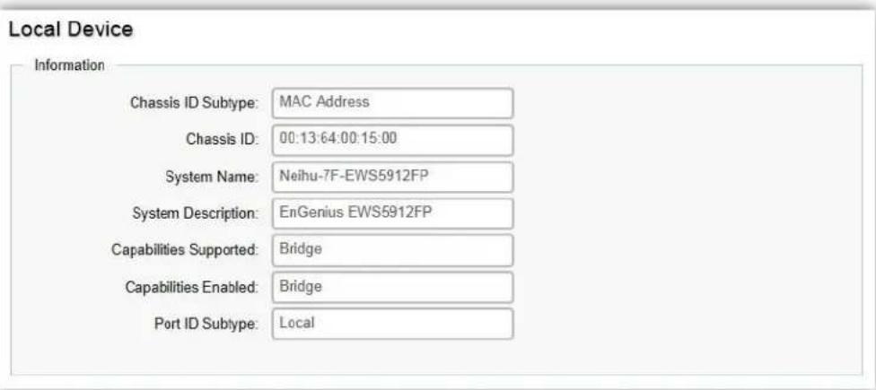
| Chassis ID Subtype | Displays the chassis ID type. |
| Chassis ID | Displays the chassis ID of the device transming the LLDP frame. |
| System Name | Displays the administratively assigned device name. |
| System Descripon | Describes the device. |
| Capabilities Supported | Describes the device funcons. |
| Capabilities Enabled | Describes the device funcons. |
| Port ID Subtype | Displays the port ID type. |
Remote Device
LLDP devices must support chassis and port ID adversement, as well as the system name, system ID, system descripon, and system capability adversements. From here you can viewing detailed LLDP Informaon for the remote device.
| Port | Chassis IDSubtype | Chassis ID | Port IDSubtype | RemoteID | System Name | Time To Live | Auto-Negotiation Supported | Auto-Negotiation Enabled | Auto-Negotiation Advertised Capabilities | Operational MAU Type | 802.3 Maximum Frame Size | 802.3 Link Aggregation Capability | 802.3 Link Aggregation Status | 802.3 Link Aggregation Port ID |
| 2 | MAC address | 03 021F FE:94 46 | Interface name | eth0 | James_test_EWS19SAP | 72 | Disabled | Disabled | 0 | 0 | ||||
| 10 | MAC address | 81 DC 96.10 6A:05 | Locally assigned | g3 | EGS7252FP | 114 | Enabled | Enabled | 10BASE-T half duplex, 10BASE-T full duplex, 10BASE-TX half duplex, 10BASE-TX full duplex, 100BASE-T full duplex | 100BASE-T full duplex mode | 1522 | Capable of being aggregated | Not currently in aggregation | 0 |
| Port | Displays the port. |
| Chassis ID Subtype | Displays the chassis ID type. |
| Chassis ID | Displays the chassis ID of the device that is transming the LLDP frame. |
| Port ID Subtype | Displays the port ID type. |
| Remote ID | Displays the remote ID. |
| System Name | Displays the administratively assigned device name. |
| Time to Live | Displays the me to live. |
| Auto-Negoaon Supported | Displays state for the auto-negoaon supported. |
| Auto-Negoaon Enabled | Displays state for the auto-negoaon enabled. |
| Auto-Negoaon Adversed Capabilities | Displays the type of auto-negoaon adversed capabilities. |
| Operaonal MAU Type | Displays the type of MAU. |
| 802.3 Maximum Frame Size | Displays the maximum size of 802.3 maximum frame. |
| 802.3 Link Aggregaon Capabilities | Displays the 802.3 Link Aggregaon capabilities. |
| 802.3 Link Aggregaon Status | Displays the status of 802.3 Link Aggregaon. |
| 802.3 Link Aggregaon Port ID | Displays the port ID of 802.3 Link Aggregaon. |
IGMP Snooping
Internet Group Management Protocol (IGMP) Snooping allows a Switch to forward mulcast trac intelligently. Mulcasng is used to support real-me applicaons such as video conferencing or streaming audio. A mulcast server does not have to establish a separate conncon with each client. It merely broadcasts its service to the network, and any host that wishes to receive the mulcast register with their local mulcast Switch.
A mulcast group is a group of end nodes that want to receive mulcast packets from a mulcast applicaon. Aer joining a mulcast group, a host node must connue to periodically issue reports to remain a member. Any mulcast packets belonging to that mulcast group are then forwarded by the Switch from the port.
A Switch supporting IGMP Snooping can passively snoop on IGMP Query, Report, and Leave packets transferred between IP Mulcast switches and IP Mulcast hosts to determine the IP Mulcast group membership. IGMP Snooping checks IGMP packets passing through the network and congures mulcasng accordingly. Based on the IGMP query and report messages, the Switch forwards trac only to the ports that request the mulcast trac. It enables the Switch to forward packets of mulcast groups to those ports that have validated host nodes. The Switch can also limit ooding of trac to IGMP designated ports. This improves network performance by restricting the mulcast packets only to switch ports where host nodes are located. IGMP Snooping significantly reduces overall Mulcast trac passing through your Switch. Without IGMP Snooping, Mulcast trac is treated in the same manner as a broadcast transmission, which forwards packets to all ports on the network.
| IGMPv1 | Dened in RFC 1112. An explicit join message is sent to the Switch, but a meout is used to determine when hosts leave a group. |
| IGMPv2 | Dened in RFC 2236. Adds an explicit leave message to the join message so that Switch can more easily determine when a group has no interested listeners on a LAN. |
| IGMPv3 | Dened in RFC 3376. Support for a single source of content for a mulcast group. |
Global Settings
Click to enable or disable the IGMP Snooping feature for the Switch. Next, select whether you wish to use V2 or V3. Finally, select whether you wish to enable or disable the Report Suppression feature for the Switch.
Global Settings
Settings
Status:
○Enabled
●Disabled
Version:
V2
OV3
Report Suppression:
Enabled
○Disabled
Apply
| Status | Select to enable or disable IGMP Snooping on the Switch. The Switch snoops all IGMP packets it receives to determine which segments should receive packets directed to the group address when enabled. The default seng is: Disabled. |
| Version | Select the IGMP version you wish to use. If an IGMP packet received by the interface has a version higher than the specied version, this packet will be dropped. |
| Report Suppression | Select whether Report Suppression is Enabled or Disabled for IGMP Snooping. The Report Suppression feature limits the amount of membership reports the member sends to mulcast capable routers. |
Click Apply to update the system sengs.
VLAN Settings
Use the IGMP Snooping VLAN Sengs to congregate IGMP Snooping sengs for VLANs on the system. The Switch performs IGMP Snooping on VLANs that send IGMP packets. You can specify the VLANs that IGMP Snooping should be performed on. Choose from the drop down box whether to enable or disable IGMP Snooping. Next, choose to enable or disable Fast Leave for the VLAN ID.

| VLAN ID | Displays the VLAN ID. |
| IGMP Snooping Status | Enables or disables the IGMP Snooping feature for the specied VLAN ID. |
| Fast Leave | Enables or disables the IGMP Snooping Fast Leave for the specied VLAN ID. Enabling this feature allows the Switch to immediately remove the Layer 2 LAN port from its forwarding table entry upon receiving an IGMP leave message without rst sending out IGMPgroup-specific (GS) queries to the port. |
Click the Apply button √ to accept the changes or the Cancel buon ✗ to discard them.
If Fast Leave is not used, a mulcast querier will send a GS-query message when an IGMPv2/v3 group leave message is received. The querier stops forwarding trac for that group only if no host replies to the query within the specied meout period. If Fast Leave is enabled, the Switch assumes that only one host is connected to the port. Therefore, Fast Leave should only be enabled on a port if it is connected to only one IGMP-enabled device.
Fast Leave is supported only with IGMPv2 or IGMPv3 Snooping when IGMP Snooping is enabled. Fast Leave does not apply to a port if the Switch has learned that a mulcast querier is aached to it.
Fast Leave can improve bandwidth usage for a network which frequently experiences many IGMP host add and leave requests.
Querier Settings
IGMP Snooping requires that one central Switch to periodically query all end devices on the network to announce their mulcast memberships and this central device is the IGMP querier. The snooping Switch sends out periodic queries with a me interval equal to the congured querier query interval. The IGMP query keeps the Switch updated with the current mulcast group membership informaon. If the Switch does not receive the updated membership informaon, then it will stop forwarding mulcasts to specied VLANs.
| Querier Settings | |||||||||||||
| VLAN ID | Querier State | Querier Version | Querier Status | Querier IP | Robustness | Interval | Oper Interval | Max Response Interval | Oper Max Response Interval | Last Member Query Counter | Oper Last Member Query Counter | Last Member Query Interval | Oper Last Member Query Interval |
| 1 | Disabled | U2 | Non-Counter | — | 2 | 125 | 125 | 10 | 10 | 2 | 2 | 1 | 1 |
| VLAN ID | Displays the VLAN ID. |
| Querier State | Select whether to enable or disable the IGMP querier state for the specied VLAN ID.A querier can periodically ask their hosts if they wish to receive mulcast trac. The querier feature will check whether hosts wish to receive mulcast trac when enabled. An elected querier will assume the role of querying the LAN for group members, and then propagates the service requests on to any upstream mulcast Switch to ensure that it will connue to receive the mulcast service. This feature is only supported for IGMPv1 and v2 snooping. |
| Querier Version | Enter the version of IGMP packet that will be sent by this port. If an IGMP packet received by the port has a version higher than the specied version, this packet will be dropped. |
| Robustness | Provides ne-tuning to allow for expected packet loss on a subnet. It is used in calculang the following IGMP message intervals. The default is 2. |
| Interval | Enter the amount of me in seconds between general query transmissions. The default is 125 seconds. |
| Oper Interval | Displays the IGMP Interval of the operaonal querier. |
| Max Response Interval | Enter the maximum response me used in the queries that are sent by the snooping querier. The default is 10 seconds. |
| Oper Max Response Interval | Display the maximum response me which used in the queries that are sent by the snooping querier. |
| Last Member Query | Enter the number of the operaonal last member querier. |
| Counter | |
| Oper Last Member Query Counter | Enter the number of IGMP group-specific queries sent before the switch assumes there are no local members. |
| Last Member Query Interval | Enter the me between two consecutive group-specific queries that are sent by the querier, including those sent in response to leave group messages. You might lower this interval to reduce the amount of me it takes a querier to detect the loss of the last member of a group. |
| Oper Last Member Query Interval | Displays the operaonal last member query interval sent by the elected querier. |
Click the Apply button √ to accept the changes or the Cancel button ✗ to discard them.
Group List
The Group List displays VLAN ID, group IP address, and members port in the IGMP Snooping list.
| Group List | ||
| VLAN ID | Group IP Address | Member Ports |
Router Settings
The Router Sengs shows the learned mulcast router aached port if the port is acve and a member of the VLAN. Select the VLAN ID you would like to conjure and enter the Stac and Forbidden ports for the specied VLAN IDs. All IGMP packets snooped by the Switch will be forwarded to the mulcast router reachable from the port.

| VLAN ID | Displays the VLAN ID. |
| Router Ports Auto-Learned | The Switch will auto detect the presence of a mulcast router and forward IGMP packets accordingly. |
| Dynamic Port List | Displays router ports that have been dynamically congured. |
| Forbidden Port List | Designates a range of ports as being disconnected to mulcast-enabled routers. Ensures that the forbidden router port will not propagate round packets out. |
| Stac Port list | Designates a range of ports as being connected to mulcast-enabled routers. Ensures that all the packets will reach the mulcast-enabled router. |
Click the Apply button √ to accept the changes or the Cancel button ✗ to discard them.
MLD Snooping
Mulcast Listener Discovery (MLD) Snooping operates on the IPv6 trac level for discovering mulcast listeners on a directly aached port and performs a similar funcon to IGMP Snooping for IPv4. MLD snooping allows the Switch to examine MLD packets and make forwarding decisions based on content. MLD Snooping limits IPv6 mulcast trac by dynamically conguring the Switch port so that mulcast trac is forwarded only to those ports that wish to receive it. This reduces the ooding of IPv6 mulcast packets in the specied VLANs. Both IGMP and MLD Snooping can be acve at the same me.
Global Settings
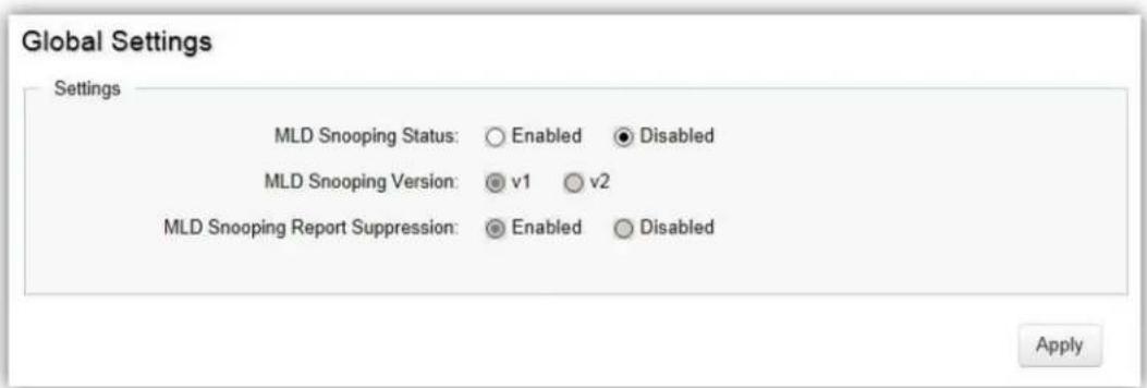
| VLAN ID | Displays the VLAN ID. |
| Router Ports Auto-Learned | The Switch will auto detect the presence of a mulcast router and forward IGMP packets accordingly. |
| Dynamic Port List | Displays router ports that have been dynamically congured. |
| Forbidden Port List | Designates a range of ports as being disconnected to mulcast-enabled routers. Ensures that the forbidden router port will not propagate round packets out. |
| Stac Port list | Designates a range of ports as being connected to mulcast-enabled routers. Ensures that all the packets will reach the mulcast-enabled router. |
Click Apply to update the system sengs.
VLAN Settings
If the Fast Leave feature is not used, a mulcast querier will send a GS-query message when an MLD group leave message is received. The querier stops forwarding trac for that group only if no host replies to the query within the specied meout period. If Fast Leave is enabled, the Switch assumes that only one host is connected to the port. Therefore, Fast Leave should only be enabled on a port if it is connected to only one MLD-enabled device.

Fast Leave does not apply to a port if the Switch has learned that a mulcast querier is aached to it. Fast Leave can improve bandwidth usage for a network which frequently experiences many MLD host add and leave requests.
| VLAN ID | Displays the VLAN ID. |
| MLD Snooping Status | Select to enable or disable the MLD snooping feature for the specied VLAN ID. |
| Fast Leave | Enables or disables the MLD snooping Fast Leave feature for the specied VLAN ID. Enabling this feature allows the Switch to immediately remove the Layer 2 LAN port from its forwarding table entry upon receiving an MLD leave message without rst sending out an MLD group-specific (GS) query to the port. |
Select from the drop down list whether to enable or disable MLD Snooping. Next, select to enable or disable Fast Leave for the specied VLAN ID.
Click the Apply button √ to accept the changes or the Cancel buon ✗ to discard them.
Group List
The Group List displays the VLAN ID, IPv6 address, and members port in the MLD Snooping List.

Router Settings
The Router Sengs feature shows the learned mulcast router aached port if the port is acve and a member of the VLAN. Select the VLAN ID you would like to conjure and enter the stac and forbidden ports for the specied VLAN IDs that are ulizing MLD Snooping. All MLD packets snooped by the Switch will be forwarded to the mulcast router reachable from the port.

| VLAN ID | Displays the VLAN ID. |
| Router Ports Auto-Learned | The Switch will automatically detect the presence of a mulcast router and forward MLD packets accordingly. |
| Dynamic Port List | Displays router ports that have been dynamically congured. |
| Forbidden Port List | Designates a range of ports as being disconnected to mulcast-enabled routers. Ensure that the forbidden router port will not propagate round packets out. |
| Stac Port List | Designates a range of ports as being connected to mulcast-enabled routers. Ensure that all the packets will reach the mulcast-enabled router. |
Click the Apply button √ to accept the changes or the Cancel button ✗ to discard them.
Jumbo Frame
Ethernet has used the 1500 byte frame size since its inception. Jumbo frames are network-layer PDUs that have a size much larger than the typical 1500 byte Ethernet Maximum Transmission Unit (MTU) size. Jumbo frames extend Ethernet to 9000 bytes, making them large enough to carry an 8 KB application datagram plus packet header overhead. If you intend to leave the local area network at high speeds, the dynamics of TCP will require you to use large frame sizes.
The switch supports a jumbo frame size of up to 9216 bytes. Jumbo frames need to be congured to work on the ingress and egress port of each device along the end-to-end transmission path. Furthermore, all devices in the network must also be consistent on the maximum jumbo frame size, so it is important to do a thorough investigaon of all your devices in the communicaon paths to validate their sengs.

| Jumbo Frame | Enter the size of jumbo frame. The range is from 1522 to 9216 bytes. |
Click Apply to update the system sengs.
VLAN
A Virtual LAN (VLAN) is a group of ports that form a logical Ethernet segment on a Layer 2 Switch which provides beer administraon, security, and management of mulcast trac. A VLAN is a network topology congured according to a logical scheme rather than a physical layout. When you use a VLAN, users can be grouped by logical funcon instead of physical locaon. All ports that frequently communicate with each other are assigned to the same VLAN, regardless of where they are physically on the network. VLANs let you logically segment your network into dierent broadcast domains so that you can group ports with related funcons into their own separate, logical LAN segments on the same Switch. This allows broadcast packets to be forwarded only between ports within the VLAN which can avoid broadcast packets being sent to all the ports on a single Switch. A VLAN also increases network performance by liming broadcasts to a smaller and more manageable logical broadcast domain. VLANs also improve security by liming trac to specific broadcast domains.
802.1Q
Each VLAN in a network has an associated VLAN ID, which appears in the IEEE 802.1Q tag in the Layer 2 header of packets transmied on a VLAN. The IEEE 802.1Q specicaon establishes a standard method for tagging Ethernet frames with VLAN membership informaon. The key for IEEE 802.1Q to perform its funcons is in its tags. 802.1Q-compliant Switch ports can be congured to transmit tagged or untagged frames. A tag eld containing VLAN informaon can be inserted into an Ethernet frame. When using 802.1Q VLAN conguraon, you congure ports to be a part of a VLAN group. When a port receives data tagged for a VLAN group, the data is discarded unless the port is a member of the VLAN group.
802.1Q
For the Controller to function properly, make sure that all ports (on all cascading switches as well) connected to APs on the switch are configured as the same VLAN ID as the Controller's Management VLAN ID.
VID
Name
default
Tagged Port
Untagged Port
1-12.11-18


| Enabled | Enables 802.1Q VLANs. This feature is enabled by default. |
| VID | Displays the VLAN ID for which the network policy is dened. The range of the VLAN ID is from 1 to 4094. |
| Name | Enter the VLAN name. You can use up to 32 alphanumeric characters. |
| Tagged Port | Frames transmied from this port are tagged with the VLAN ID. |
| Untagged Port | Frames transmied from this port are untagged. |

NOTE
The Switch's default seng is to assign all ports to a single 802.1Q VLAN(VID 1).
Please keep this in mind when conguring the VLAN sengs for the Switch.
PVID
When an untagged packet enters a Switch port, the PVID (Port VLAN ID) will be aached to the untagged packet and forward frames to a VLAN specied VID part of the PVID. A packet received on a given port would be assigned that port's PVID and then be forwarded to the port that corresponded to the packet's desnaon address. If the PVID of the port that received the packet is dierent from the PVID of the port that is to transmit the packet, the Switch will drop the packet. Within the Switch, dierent PVIDs mean dierent VLANs, so VLAN idencaon based upon the PVIDs cannot create VLANs that extend outside a given Switch. If no VLANs are dened on the Switch, all ports are then assigned to a default VLAN with a PVID equal to 1.
PVID
For the Controller to function properly, make sure that all ports (on all cascading switches as well) connected to APs on the switch are configured as the same VLAN ID as the Controller's Management VLAN ID.
| Port | PVID | Accept Type | Ingress Filtering | |
| 1 ~ 4094 | ALL | Enabled | ||
| 1 | 1 | ALL | Enabled | |
| 2 | 1 | ALL | Enabled | |
| 3 | 1 | ALL | Enabled | |
| 4 | 1 | ALL | Enabled | |
| 5 | 1 | ALL | Enabled | |
| 6 | 1 | ALL | Enabled | |
| 7 | 1 | ALL | Enabled | |
| 8 | 1 | ALL | Enabled | |
| 9 | 1 | ALL | Enabled | |
| 10 | 1 | ALL | Enabled | |
| 11 | 1 | ALL | Enabled | |
| 12 | 1 | ALL | Enabled | |
| trunk1 | 1 | ALL | Enabled | |
| trunk2 | 1 | ALL | Enabled |
| Port | Displays the VLAN ID to which the PVID tag is assigned. Congure the PVID to assign untagged or tagged frames received on the selected port. |
| PVID | Enter the PVID value. The range is from 1 to 4094. |
| Accept Type | Select Tagged Only and Untagged Only from the list.Tagged Only: The port discards any untagged frames it receives. The port onlyaccepts tagged frames.Untagged Only: Only untagged frames received on the port are accepted.All: The port accepts both tagged and untagged frames. |
| Ingress Filtering | Specify how you wish the port to handle tagged frames. Select Enabled or Disabled from the list.Enabled: Tagged frames are discarded if VID does not match the PVID of the port.Disabled: All frames are forwarded in accordance with the IEEE 802.1Q VLAN. |

NOTE
To enable PVID funconality, the following requirements must be met:
All ports must have a dened PVID.
If no other value is specied, the default VLAN PVID is used.
If you wish to change the port's default PVID, you must rst create a VLAN that includes the port as a member.
Click Apply to update the system sengs.
Management VLAN
The Management VLAN allows users to transfer the authority of the Switch from the default VLAN to other VLAN IDs. By default, the acve management VLAN ID is 1, which allows an IP conncon to be established through any port. When the management VLAN is set to a dierent VLAN, connecvity through the exisng management VLAN is lost and an IP conncon can be made only through a port that is part of the management VLAN. It is also mandatory that the port VLAN ID (PVID) of the port to be connected in that management VLAN be the same as the management VLAN ID.
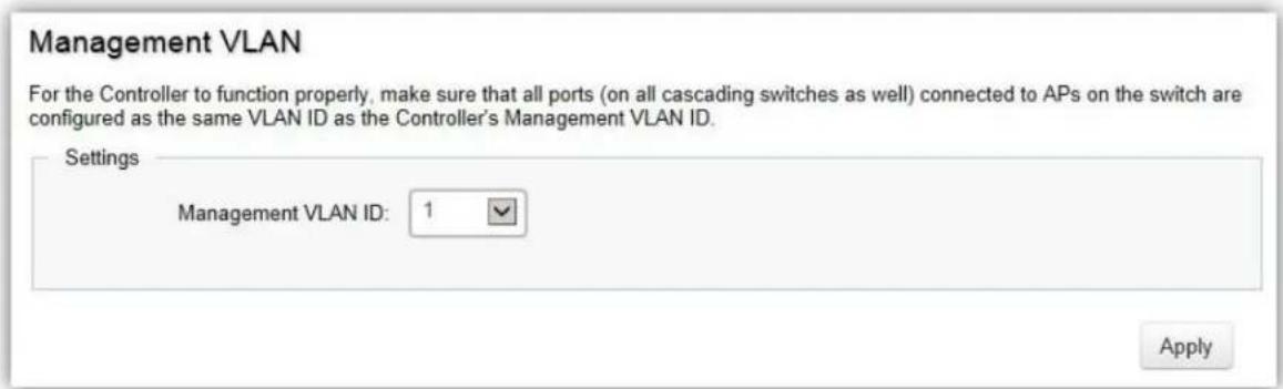
Click Apply to update the system sengs.
Voice VLAN
Enhance your Voice over IP (VoIP) service by conguring ports to carry IP voice trac from IP phones on a specific VLAN. Voice VLAN provides QoS to VoIP, ensuring that the quality of the call does not deteriorate if the IP trac is received erracally or unevenly.
Global Settings

| Voice VLAN State | Select Enabled or Disabled for Voice VLAN on the Switch. |
| Voice VLAN ID | Sets the Voice VLAN ID for the network. Only one Voice VLAN is supported on the Switch. |
| 802.1p Remark | Enable this funcon to have outgoing voice trac to be marked with the selected CoS value. |
| RemarkCoS/802.1p | Denes a service priority for trac on the Voice VLAN. The priority of any received VoIP packet is overwrien with the new priority when the Voice VLAN feature is acve on a port. (Range: 0 to 7; Default: 6) |
| Aging Time | The aging me is used to remove a port from voice VLAN if the port is an automac VLAN member. When the last voice device stops sending trac and the MAC address of this voice device is aged out, the voice VLAN aging mer will be started. The port will be removed from the voice VLAN aer expiraon of the voice VLAN aging mer. If the voice trac resumes during the aging me, the aging mer will be reset and stop. The range for aging me is from 1 to 65535 minutes. The default is 1440 minutes. |
Click Apply to update the system sengs.
OUI Settings
The Switches determines whether a received packet is a voice packet by checking its source MAC address. VoIP trac has a pre-congured Organizaonally Unique Ideners (OUI) prex in the source MAC address. You can manually add specic manufacturer's MAC addresses and descripon to the OUI table. All trac received on the Voice VLAN ports from the specic IP phone with a listed OUI is forwarded on the voice VLAN.
OUI Settings
| Index | OUI Address | Description | + Add |
| 1 | 00:E0:BB | 3COM | |
| 2 | 00:03:6B | Cisco | |
| 3 | 00:E0:75 | Veritel | |
| 4 | 00:D0:1E | Pingtel | |
| 5 | 00:01:E3 | Siemens | |
| 6 | 00:60:B9 | NEC/Philips | |
| 7 | 00:0F:E2 | H3C | |
| 8 | 00:09:6E | Avaya |
| Index | Displays the VoIP sequence ID. |
| OUI Address | This is the globally unique ID assigned to a vendor by the IEEE to identify VoIP equipment. |
| Descripon | Displays the ID of the VoIP equipment vendor. |
To congregate the OUI settings, click the Edit button to re-convagure the specific entry. Click the Delete buon to remove the specific entry and click the Add buon to create a new OUI entry.
Click the Apply button √ to accept the changes or the Cancel buon ✗ to discard them.
Port Settings
Enhance your VoIP service further by conguring ports to carry IP voice trac from IP phones on a specific VLAN. Voice VLAN provides QoS to VoIP, ensuring that the quality of voice does not deteriorate if the IP trac is received unevenly.
| Port Settings | ||||
| Port | State | CoS Mode | Operate Status | |
| □ | Disabled | Src | ||
| □ | 1 | Disabled | Src | -- |
| □ | 2 | Disabled | Src | -- |
| □ | 3 | Disabled | Src | -- |
| □ | 4 | Disabled | Src | -- |
| □ | 5 | Disabled | Src | -- |
| □ | 6 | Disabled | Src | -- |
| □ | 7 | Disabled | Src | -- |
| □ | 8 | Disabled | Src | -- |
| □ | 9 | Disabled | Src | -- |
| □ | 10 | Disabled | Src | -- |
| □ | 11 | Disabled | Src | -- |
| □ | 12 | Disabled | Src | -- |
| □ | trunk1 | Disabled | Src | -- |
| □ | trunk2 | Disabled | Src | -- |
| □ | trunk3 | Disabled | Src | -- |
| □ | trunk4 | Disabled | Src | -- |
| Port | Displays the port to which the Voice VLAN sengs are applied. |
| State | Select Enabled to enhance VoIP quality on the selected port. The default is Disabled. |
| CoS Mode | Select Src or All from the list. Src: Src QoS aributes are applied to packets with OUIs in the source MAC address. All: All QoS aributes are applied to packets that are classed to the Voice VLAN. |
| Operate Status | Displays the operang status for the Voice VLAN on the selected port. |
Click Apply to update the system sengs.
Management
System Information
The System Informaon screen contains general device informaon including the system name, system locaon, and system contact for the Switch.
System Information
Information
System Name:
Neihu-7F-EWS5912FP
(char : 1 \~ 255)
System Location:
Default Location
(char:0\~255)
System Contact:
Default Contact
(char:0\~255)
Apply
| System Name | Enter the name you wish to use to identify the Switch. You can use up to 255 alphanumeric characters. |
| System Locaon | Enter the locaon of the Switch. You can use up to 255 alphanumeric characters. The factory default is: Default Locaon. |
| System Contact | Enter the contact person for the Switch. You can use up to 255 alphanumeric characters. The factory default is: Default Locaon. |
Click Apply to update the system sengs.
User Management
Use the User Management page to control management access to the Switch based on manually congured user names and passwords. A User account can only view sengs without the right to congure the Switch, and an Admin account can congure all the funcons of the Switch. Click the Add buon to add an account or the Edit buon to edit an exisng account.
| User Management | |||||
| User Name | Password Type | Password | Password Retype | Privilege Type | + Add |
| admin | Encrypted | Admin | |||
| User Name | Enter a username. You can use up to 18 alphanumeric characters. |
| Password Type | Select Clear Text or Encrypted from the list. |
| Password | Enter a new password for accessing the Switch. |
| Password Retype | Repeat the new password used to access the Switch. |
| Privilege Type | Select Admin or User from the list to regulate access rights. |

Important:
Note that Admin users have full access rights to the Switch when determining the authority of the user account.
Click the Apply button √ to accept the changes or the Cancel buon ✗ to discard them.
Dual Image
The Switch maintains two versions of the Switch image in its permanent storage. One image is the acve image, and the second image is the backup image. The Dual Image screen enables the user to select which paron will be set as acve aer the next reset. The Switch boots and runs from the acve image. If the acve image is corrupt, the system automacally boots from the non-acve image.
| Dual Image | |||||
| Active | Flash Partition | Status | Image Name | Image Size(Byte) | Created Time |
| ○ | Partition 0 | Backup | IMG-1.05.16-c1.5.3 | 8273849 | 2015-07-07 21:50:12 |
| ● | Partition 1 | Active | IMG-1.05.26-c1.6.24 | 7320132 | 2015-11-13 13:38:03 |
| Acve | Selects the paron you wish to be acve. |
| Flash Paron | Displays the number of the paron. |
| Status | Displays the paron which is currently acve on the Switch. |
| Image Name | Displays the name/version number of the image |
| Image Size | Displays the size of the image le. |
| Created Time | Displays the me the image was created. |
Click Apply to update the system sengs.
SNMP
Simple Network Management Protocol (SNMP) is an applicaon layer protocol designed specifically for managing and monitoring network devices. Simple Network Management Protocol (SNMP) is a popular protocol for network management. It is used for collecng informaon from and conguring network devices such as; servers, printers, hubs, Switches, and routers on an Internet Protocol (IP) network. SNMP is used to exchange management informaon between a network management system (NMS) and a network device. A manager staon can manage and monitor the Switch through their network via SNMPv1, v2c and v3. An SNMP managed network consists of two components; agents and a manager.
An agent translates the local management informaon from the managed Switch into a form that is compatible with SNMP. SNMP allows a manager and agents to communicate with each other for the purpose of accessing Management Informaon Bases (MIBs). SNMP uses an extensible design, where the available informaon is dened by MIBs. MIBs describe the structure of the management data of a device subsystem; they use a hierarchical namespace containing Object Ideners (OID). Each OID idenes a variable that can be read or set via SNMP.
The manager is the console through which network administrators perform network management funcons.
Several versions of SNMP are supported. They are v1, v2c, and v3. SNMPv1, which is dened in RFC 1157 "A Simple Network Management Protocol (SNMP)", is a standard that denies how communicaon occurs between SNMP-capable devices and species the SNMP message types. Version 1 is the simplest and most basic of versions. There may be mes where it's required to support older hardware. SNMPv2c, which is dened in RFC 1901 "Introducon to Community-Based SNMPv2", RFC 1905, "Protocol Operaons for Version 2 of the Simple Network Management Protocol (SNMPv2)", and RFC 1906 "Transport Mappings for Version 2 of the Simple Network Management Protocol (SNMPv2)". SNMPv2c updates protocol operaons by introducing a GetBulk request and authencaon based on community names. Version 2c adds several enhancements to the protocol, such as support for "Informs". Because of this, v2c has become the most widely used version. Unfortunately, a major weakness of v1 and v2c is security. To combat this, SNMP v3 adds a security features that overcome the weaknesses in v1 and v2c. If possible, it is recommended that you use v3 — especially if you plan to transmit sensitive informaon across unsecured links. However, the extra security feature makes conguraon a lile more complex.
In SNMPv3, User-based Security Model (USM) authencaon is implemented along with encrypon, allowing you to congregate a secure SNMP environment. The SNMPv3 protocol uses different terminology
than SNMPv1 and SNMPv2c as well. In the SNMPv1 and SNMPv2c protocols, the terms agent and manager are used. In the SNMPv3 protocol, agents and managers are renamed to enes. With the SNMPv3 protocol, you create users and determine the protocol used for message authencaon as well as if data transmied between two SNMP enes is encrypted.
The SNMPv3 protocol supports two authencaon protocols - HMAC-MD5-96 (MD5) and HMAC-SHA-96 (SHA). Both MD5 and SHA use an algorithm to generate a message digest. Each authencaon protocol authencates a user by checking the message digest. In addition, both protocols use keys to perform authencaon. The keys for both protocols are generated locally using the Engine ID and the user password to provide even more security.
In SNMPv1 and SNMPv2c, user authencaon is accomplished using types of passwords called Community Strings, which are transmied in clear text and not supported by authencaon. Users can assign views to Community Strings that specify which MIB objects can be accessed by a remote SNMP manager.
The default Community Strings for the Switch used for SNMPv1 and SNMPv2c management access for the Switch are public, which allows authorized management staons to retrieve MIB objects, and private, which allow authorized management staons to retrieve and modify MIB objects.
Global Settings
Simple Network Management Protocol (SNMP) is an OSI Layer 7 (Applicaon Layer) protocol designed specifically for managing and monitoring network devices. The SNMP agents maintain a list of variables that are used to manage the device. The variables are dened in the Management Informaon Base (MIB), which provides a standard presentaon of the informaon controlled by the on-board SNMP agent.
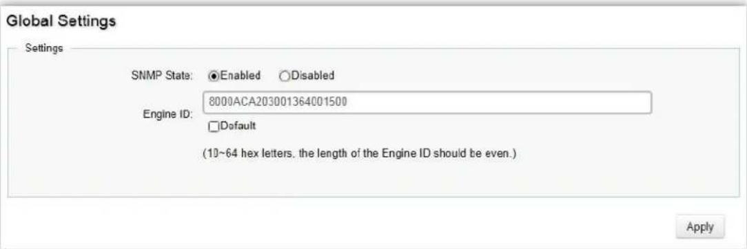
| SNMP State | Enables or disables the SNMP funcon. The default SNMP global state is: Enabled. |
| Local Engine ID(10-64 hex characters) | Enter the Switch's Engine ID for the remote clients. A SNMPv3 engine is an independent SNMP agent that resides on the Switch. This engine protects against message replay, delay, and redirecon issues. The engine ID is also used in combinaon with user passwords to generate security keys for authencang and encrypng SNMPv3 packets. Normally, a local engine ID is automacally generated that is unique to the Switch. This is referred to as the default engine ID. If the local engine ID is deleted or changed, all local SNMP users will be cleared and you will need to reconfigure all exisng users. |
Click Apply to update the system sengs.
View List
SNMP uses an extensible design, where the available informaon is dened by Management Informaon Bases (MIBs). MIBs describe the structure of the management data of a device subsystem; they use a hierarchical namespace containing Object Ideners (OID) to organize themselves. Each OID idenes a variable that can be read or set via SNMP. The SNMP View List is created for the SNMP management staon to manage MIB objects.
Click the Add buon to create a new entry.

| View Name | Enter the view name. The view name can contain up to 30 alphanumeric characters. |
| Subtree OID | Enter the Object Idener (OID) Subtree. The OID idenes an object tree (MIB tree) that will be included or excluded from access by an SNMP manager. Note that the rst character must be a period (.). Wild cards can be used to mask a specic poron of the OID string using a period (.). |
| Subtree Mask | Select 0 or 1 for Subtree mask. The mask of the Subtree OID 1 means this object number "is concerned", and 0 means "do not concern". |
| View Type | Select whether the dened OID branch within MIB tree will be Included or Excluded from the selected SNMP view. Generally, if the view type of an entry is Excluded, another entry of view type Included should exist and its OID subtree should overlap the Excluded view entry. |
Click the Apply button

to accept the changes or the Cancel button

to discard them.
Group List
Congure SNMP Groups to control network access on the Switch by providing users in various groups with dierent management rights via the Read View, Write View, and Nofy View opons.

| Group Name | Enter the group name that access control rules are applied to. The group name can contain up to 30 alphanumeric characters. |
| Security Mode | Selects the SNMP version (v1, v2c, v3) associated with the group. |
| Security Level | Select the security level for the group. Security levels apply to SNMPv3 only.No Auth: Neither authencaon nor the privacy security levels are assigned to the group.Auth: Authencates SNMP messages.Priv: Encrypts SNMP messages. |
| Read View | Management access is restricted to read-only. |
| Write View | Select a SNMP to allow SNMP write privileges to the Switch's SNMP agent. |
| Nofy View | Select a SNMP group to receive SNMP trap messages generated by the Switch's SNMP agent. |
Click the Apply button √ to accept the changes or the Cancel button ✗ to discard them.
Community List
In SNMPv1 and SNMPv2c, user authencaon is accomplished using types of passwords called Community Strings, which are transmied in clear text and not supported by authencaon. It is important to note that the community name can limit access to the SNMP agent from the SNMP network management staon, functioning as a password.
Click Add to add a community list to the Switch. Next, name the community and choose the level of access that will be granted to the specied list from the drop down boxes.
| Community List | ||||
| Community Name | Community Mode | Group Name | View Name | Access Rights |
| private | Basic | all | Read Write | |
| public | Basic | all | Read Only | |
| char: 1~20 | Basic | all | Read Only | |
| Community Name | Enter the name of SNMP community string. |
| Community Mode | Selected Basic or Advance from the list. Select the Advance aached to the SNMP group. |
| Group Name | Select the SNMP group from a list. |
| View Name | Select the view name from a list. |
| Access Rights | Specify the level of permission for the MIB objects accessible to the SNMP. Your choices are Read/Write or Read-only. |
Click the Apply button

to accept the changes or the Cancel buon

to discard them.
User List
Use the User List page to create SNMP users for authencaon with managers using SNMP v3 to associate them to SNMP groups. Click Add to add a new user.
| User List | ||||||
| User Name | Group Name | Privilege Mode | Authentication Protocol | Authentication Password | Encryption Protocol | Encryption Key |
| char : 4 ~ 30 | No Aut | char : 6 ~ 32 | None | char : 8 ~ 64 | ||
| Privilege Mode | Select No Auth, Auth, or Priv security level from the list.No auth: Neither authencaon nor the privacy security levels are assigned to the group.Auth: Authencates and ensures that the origin of the SNMP message is authenticated.Priv: Encrypts SNMP messages. |
| Authencaon Protocol | Select the method used to authenticate users.MD5: Using the HMAC-MD5 algorithm.SHA: Using the HMAC-SHA-96 authencaon level. Enter the SHA password and the HMAC-SHA-96 password to be used for authencaon. |
| Authencaon Password | Enter MD5 password and the HMAC-MD5-96 password to be used for authencaon. |
| Encrypon Protocol | Select the method used to authenticate users.None: No user authencaon is used.DES: Using the Data Encrypon Standard algorithm. |
| Encrypon Key | Enter the Data Encrypon Standard key. |
Click the Apply button

to accept the changes or the Cancel buon

to discard them.
Trap Settings
A trap is a type of SNMP message. The Switch can send traps to an SNMP manager when an event occurs.
You can restrict user privileges by specifying which porons of the MIBs that a user can view. In this way, you restrict which MIBs a user can display and modify for beer security. In addition, you can restrict the types of traps users can send as well. You can do this by determining where messages are sent and what types of messages can be sent per user. Traps indicang status changes can be issued by the Switch to the specied trap manager by sending authencaon failure messages and other trap messages.

| ServerIP/Hostname | Enter the server IP or Hostname. The Hostname can contain up to 128 alphanumeric characters. |
| SNMP Version | Select theSNMPversion from the list. |
| Nofy Type | Select the type of nocaon to be sent.Traps:Traps are sent.Informs:Informs are sent ONLY when v2c is enabled. NOTE:The recipient of a trap message does not send a response to the Switch. Traps are therefore not as reliable as inform messages, which include a request for acknowledgment of receipt. Inform messages can be used to ensure that crical informaon is received by the host. However, please note that informs consume more system resources because they must be kept in memory unl a response is received. Informs also add to network trac. You should consider these eects when deciding whether to issue nocaons as traps or informs. NOTE:The recipient of a trap message does not send a response to the Switch. Traps are therefore not as reliable as inform messages, which include a request for acknowledgment of receipt. Inform messages can be used to ensure that crical informaon is received by the host. However, please note that informs consume more system resources because they must be kept in memory unl a response is received. Informs also add to network trac. You should consider these eects when deciding whether to issue nocaons as traps or informs. |
| Community Name | Select the Community Name from the list. |
| UDP | Enter the UDP port used to send nocaons. |
| Timeout | Congurable only if the nofy type isInforms.Enter the amount of me the device waits before re-sending. The default is 15 seconds. |
| Retry | Congurable only if the nofy type isInforms.Enter the amount of me thedevice waits before re-sending an inform request. The default is 3 seconds. |
Click the Apply button √ to accept the changes or the Cancel buon ✗ to discard them.
ACL
An Access Control List (ACL) allows you to denote classicaon rules or establish criteria to provide security to your network by blocking unauthorized users and allowing authorized users to access specific areas or resources. ACLs can provide basic security for access to the network by controlling whether packets are forwarded or blocked at the Switch ports. Access Control Lists (ACLs) are Iters that allow you to classify data packets according to a particular content in the packet header, such as the source address, desnaon address, source port number, desnaon port number, and more. Packet classifiers identify ows for more efficient processing. Each Iter denotes the conditions that must match for inclusion in the Iter. ACLs (Access Control Lists) provide packetitering for IP frames (based on the protocol, TCP/UDP port number or frame type) or layer 2 frames (based on any desnaon MAC address for unicast, broadcast, or mulcast, or based on VLAN ID or VLAN tag priority). ACLs can be used to improve performance by blocking unnecessary network trac or to implement security controls by restricting access to specific network resources or protocols. Policies can be used to dierenate service for client ports, server ports, network ports, or guest ports. They can also be used to strictly control network trac by only allowing incoming frames that match the source MAC and source IP address on a specific port. ACLs are composed of Access Control Entries (ACEs), which are rules that determine trac classicaons. Each ACE is a considered as a single rule, and up to 256 rules may be denied on each ACL, with up to 3000 rules globally. ACLs are used to provide trac ow control, restrict contents of round updates, and determine which types of trac are forwarded or blocked. This criterion can be specified on a basis of the MAC address or IP address.
MAC ACL
This page displays the currently-dened MAC-based ACLs proles. To add a new ACL, click Add and enter the name of the new ACL.
| Index | Name | + Add |
| 1 | acl1 | |
| 2 | acl2 |
| Index | Prole idener. |
| Name | Enter the MAC based ACL name. You can use up to 32 alphanumeric characters. |
Click the Apply button √ to accept the changes or the Cancel buon ✗ to discard them.
MAC ACE
Use this page to view and add rules to MAC-based ACLs.

| ACL Name | Select the ACL from the list. |
| Sequence | Enter the sequence number which signifies the order of the specied ACL relave to other ACLs assigned to the selected interface. The valid range is from 1 to 2147483647, 1 being processed rst. |
| Acon | Select what acon taken if a packet matches the criteria. Permit: Forward packets that meet the ACL criteria. Deny: Drops packets that meet the ACL criteria. |
| Desnaon MAC Value | Enter the desnaon MAC address. |
| Desnaon MAC Wildcard Mask | Enter a MAC address mask for the desnaon MAC address. A mask of 00:00:00:00:00:00 means the bits must be matched exactly;::::: means the bits are irrelevant. Any combinaon of 0s and s can be used. |
| Source MAC Value | Enter the source MAC address. |
| Source MAC Wildcard Mask | Enter a MAC address mask for the source MAC address. A mask of 00:00:00:00:00:00 means the bits must be matched exactly;::::: means the bits are irrelevant. Any combinaon of 0s and s can be used. |
| VLAN ID | Enter the VLAN ID to which the MAC address is aached in MAC ACE. The range is from 1 to 4094. |
| 802.1p Value | Enter the 802.1p value. The range is from 0 to 7. |
| Ethertype Value | Selecng this opon instructs the Switch to examine the Ethernet type value in each frame's header. This opon can only be used to Iter Ethernet II formaed packets. A detailed lisng of Ethernet protocol types can be found in RFC 1060. A few of the more common types include 0800 (IP), 0806 (ARP), and 8137 (IPX). |
Click Apply to update the system sengs.
IPv4 ACL
This page displays the currently-dened IPv4-based ACLs proles. To add a new ACL, click Add and enter the name of the new ACL.

| Index | Displays the current number of ACLs. |
| Name | Enter the IP based ACL name. You can use up to 32 alphanumeric characters. |
Click the Apply button √ to accept the changes or the Cancel buon ✗ to discard them.
IPv4 ACE
Use this page to view and add rules to IPv4-based ACLs.
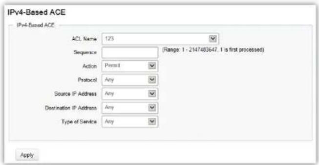
| ACL Name | Select the ACL from the list for which a rule is being created. |
| Sequence | Enter the sequence number which signifies the order of the specified ACL relave to other ACLs assigned to the selected interface. The valid range is from 1 to 2147483647, 1 being processed rst. |
| Acon | Select what acon to take if a packet matches the criteria.Permit: Forwards packets that meet the ACL criteria.Deny: Drops packets that meet the ACL criteria. |
| Protocol | Select Any, Protocol ID, or Select from a List in the drop down menu.Any: Check Any to use any protocol.Protocol ID: Enter the protocol in the ACE to which the packet is matched.Select from List: Selects the protocol from the list in the provided eld.ICMP: Internet Control Message Protocol (ICMP). The ICMP enables the gateway or desnaon host to communicate with the source host.IPinIP: IP in IP encapsulates IP packets to create tunnels between two routers. This ensures that IP in IP tunnel appears as a single interface, rather than several separate interfaces.TCP: Transmission Control Protocol (TCP). Enables two hosts to communicate and exchange data streams. TCP guarantees packet delivery, and guarantees that packets are transmied and received in the order they are sent. EGP Exterior Gateway Protocol (EGP). Permits exchanging round informaon between two neighboring gateway hosts in an autonomous systems network.IGP: Interior Gateway Protocol (IGP). Enables a round informaon exchange between gateways within an autonomous network.UDP: User Datagram Protocol (UDP). UDP is a communicaon protocol thattransmits packets but does not guarantee their delivery.HMP: The Host Mapping Protocol (HMP) collects network informaon from various networks hosts. HMP monitors hosts spread over the Internet as well as hosts in a single network.RDP: Reliable Data Protocol (RDP). Provides a reliable data transport service for packet-based applicaons.IPv6: Matches the packet to the IPV6 protocol.IPv6: Rout: Roung Header for IPv6.IPv6: Frag: Fragment Header for IPv6.RVSP: Matches the packet to the ReSerVaon Protocol(RSVP).IPv6: ICMP: The Internet Control Message Protocol (ICMP) allows the gateway or desnaon host to communicate with the source host.OSPF: The Open Shortest Path First (OSPF) protocol is a link-state hierarchical interior gateway protocol (IGP) for network roung Layer Two (2) Tunneling Protocols. It is an extension to the PPP protocolthat enables ISPs to operate Virtual Private Networks (VPNs).PIM: Matches the packet to Protocol Independent Mulcast (PIM).L2TP: Matches the packet to Internet Protocol (L2IP). |
| Source IP Address Value | Enter the source IP address. |
| Source IP Mask | Enter the mask of the new source IP address. |
| Desnaon IP Address Value | Enter the desnaon IP address. |
| Desnaon IP Mask | Enter the mask of the new source IP address. |
| Type of Service | Select Any or DSCP to match from drop down list. When DSCP to match is selected, enter the DSCP. The range is from 0 to 63. |
| ICMP Type | Select Any, Protocol ID, or Select from List from drop down menu.Protocol ID: Enter the protocol in the ACE to which the packet is matched. The range is from 0 to 255.Select from List: Select the ICMP from the list in the provided eld. |
| ICMP Code | Select Any or User Dened from drop down menu. When User Dened is selected, enter the ICMP code value. The range is from 0 to 255. |
Click Apply to update the system sengs.
IPv6 ACL
This page displays the currently-dened IPv6-based ACLs proles. To add a new ACL, click Add and enter the name of the new ACL.
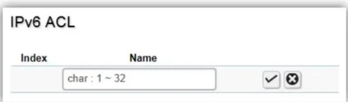
| Index | Displays the current number of ACLs. |
| Name | Enter the IPv6 based ACL name. You can use up to 32 alphanumeric characters. |
Click the Apply button

to accept the changes or the Cancel buon

o discard them.
IPv6 ACE
Allows IPv6 Based Access Control Entry (ACE) to be dened within a congured ACL.

| ACL Name | Select the ACL from the list. |
| Sequence | Enter the sequence number which signifies the order of the specified ACL relave to other ACLs assigned to the selected interface. The valid range is from 1 to 2147483647, 1 being processed rst. |
| Acon | Select what acon taken if a packet matches the criteria. Permit: Forward packets that meet the ACL criteria. Deny: Drops packets that meet the ACL criteria. |
| Protocol | Select the Any, Protocol ID, or Select from List from drop down menu. Protocol ID: Enter the protocol in the ACE to which the packet is matched. Select from List: Select the protocol from the list in the provided eld. |
| Source IP Address Value | Enter the source IP address. |
| Source IP Prex Length | Enter the prex length of the new source IP address. The range is from 0 to 128. |
| Desnaon IP Address Value | Enter the desnaon IP address. |
| Desnaon IP Prex Length | Enter the prex length of the new source IP address. The range is from 0 to 128. |
| Source Port | Select Single or Range from the list. Enter the source port that ismatched to packets. The range is from 0 to 65535. |
| Desnaon Port | Select Single or Range from the list. Enter the desnaon port that is matched to packets. The range is from 0 to 65535. |
| TCP Flags | Select whether to handle each six TCP control ags; URG (Urgent), ACK (Acknowledgment), PSH (Push), RST (Reset), SYN (Synchronize), and FIN (Fin) from drop down menu.Don't Care: The ACE do not treat the TCP control ag.Set: The packet with the TCP control ag being set matches the criteria.Unset: The packet with the TCP control ag being unset matches the criteria. |
| Type of Service | Select Any or DSCP to match from drop down list. When DSCP to match is selected, enter the DSCP. The range is from 0 to 63. |
Click Apply to update the system sengs.
ACL Binding
When an ACL is bound to an interface, all the rules that have been dened for the ACL are applied to that interface. Whenever an ACL is assigned on a port or LAG, ows from that ingress or egress interface that do not match the ACL, are matched to the default rule of dropping unmatched packets. To bind an ACL to an interface, simply select an interface and select the ACL(s) you wish to bind.
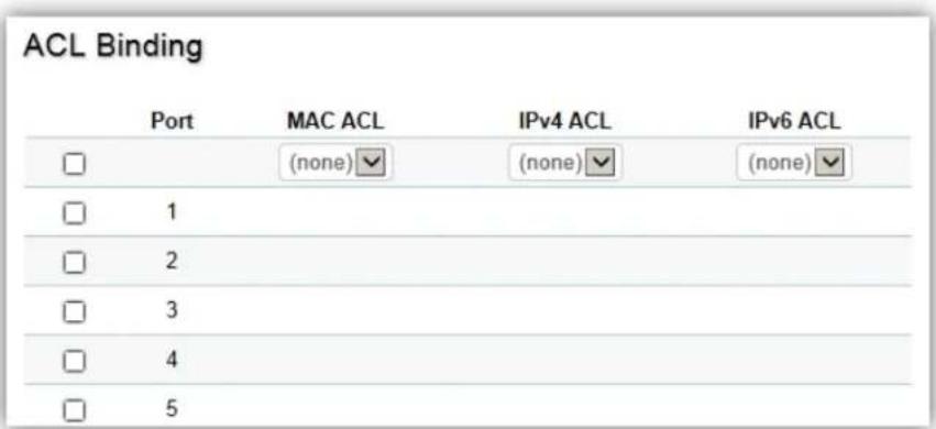
| Port | Select the port for which the ACLs are bound to. |
| MAC ACL | Select the MAC ACL rule to apply to the port. |
| IPv4 ACL | Select the IPv4 ACL rule to apply to the port. |
| IPv6 ACL | Select the IPv6 ACL rule to apply to the port. |
Click Apply to update the system sengs.
QoS
Quality of Service (QoS) provides the ability to implement priority queuing within a network. QoS is a means of providing consistent and predictable data delivery to the Switch by disnegishing between packets that have stricter ming requirements from those that are more tolerant of delays. QoS enables trac to be prioritized while avoiding excessive broadcast and mulcast trac. Trac such as Voice and Video streaming which require minimal delays can be assigned to a high priority queue, while other trac can be assigned to a lower priority queue, resulting in uninterrupted acons. Without QoS, all trac data is as likely to be dropped when the network is congested. This can result in reducons in network performance and hinder the network in me-critical situations.
In a Switch, mulple queues per port are oen provided to give preference to certain packets over others based on user-dened criteria. When a packet is queued for transmission within a port, the rate at which it is processed depends on how the queue is congured and the amount of trac present within other queues on the port. If a delay is necessary, packets are held in the queue until they are authorized for transmission.
Global Settings
There are two opons for applying QoS informaon onto packets: the 802.1p Class of Service (CoS) priority eld within the VLAN tag of tagged Ethernet frames, and Dierenated Services (DiServ) Code Point (DSCP). Each port on the Switch can be congured to trust one of the packet elds (802.1p , DSCP or DSCP+802.1p). Packets that enter the Switch's port may carry no QoS informaon as well. If so, the Switch places such informaon into the packets before transming them to the next node. Thus, QoS informaon is preserved between nodes within the network and the nodes know which label to give each packet. A trusted eld must exist in the packet for the mapping table to be of any use. When a port is congured as untrusted, it does not trust any incoming packet priority designaons and uses the port default priority value instead to process the packet.

| State | Select whether QoS is enabled or disabled on the switch. |
| Scheduling Method | Selects the Strict Priority or WRR to specify the trac scheduling method.Strict Priority: Species trac scheduling based strictly on the queue priority.WRR: Use the Weighted Round-Robin (WRR) algorithm to handle packets in priority classes of service. It assigns WRR weights to queues. |
| Trust Mode | Select which packet elds to use for classifying packets entering the Switch.DSCP: Classify trac based on the DSCP (Dierenated Services Code Point) tag value.802.1p: Classify trac based on the 802.1p. The eight priority tags that are specied in IEEE 802.1p are from 1 to 8. |
Click Apply to update the system sengs.
CoS Mapping
Use the Class of Service (CoS) Mapping feature to specify which internal trac class to map to the corresponding CoS value. CoS allows you to specify which data packets have greater precedence when trac is buered due to congeson.

| CoS | Displays the CoS priority tag values, where 0 is the lowest and 7 is the highest. |
| Queue | Check the CoS priority tag box and select the Queue values for each CoS value in the provided elds. Eight trac priority queues are supported and the eld values are from 1 to 8, where one is the lowest priority and eight is the highest priority. |
Click Apply to update the system sengs.
DSCP Mapping
Use Dierenated Services Code Point (DSCP) Mapping feature to specify which internal trac class to map to the corresponding DSCP values. DSCP Mapping increases the number of denable priority levels by reallocang bits of an IP packet for priorizaon purposes.
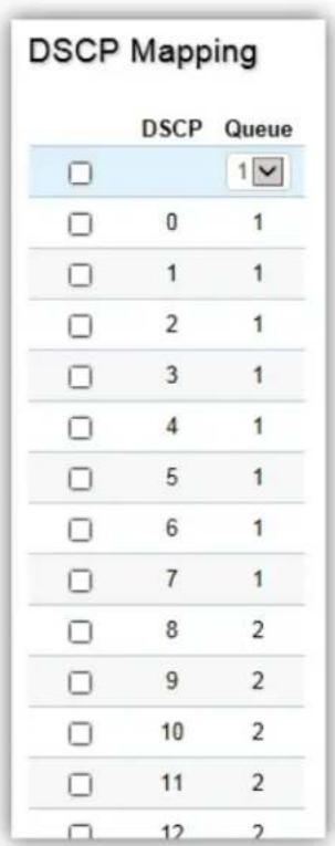
| DSCP | Displays the packet's DSCP values, where 0 is the lowest and 10 is the highest. |
| Queue | Check the CoS priority tag box and select the Queue values for each DSCP in the provided elds. Eight trac priority queues are supported and the eld values are from 1 to 8, where one is the lowest priority and eight is the highest priority. |
Click Apply to update the system sengs.
Port Settings
From here, you can congregate the QoS port sengs for the Switch. Select a port you wish to set and choose a CoS value from the drop down box. Next, Select to enable or disable the Trust seng to let any CoS packet be marked at ingress.
| Port | CoS Value | Trust | |
| Enabled | |||
| 1 | 1 | Enabled | |
| 2 | 0 | Enabled | |
| 3 | 0 | Enabled | |
| 4 | 0 | Enabled | |
| 5 | 0 | Enabled | |
| 6 | 0 | Enabled | |
| 7 | 0 | Enabled | |
| 8 | 0 | Enabled | |
| 9 | 0 | Enabled | |
| 10 | 0 | Enabled | |
| 11 | 0 | Enabled | |
| 12 | 0 | Enabled | |
| trunk1 | 0 | Enabled | |
| trunk2 | 0 | Enabled | |
| trunk3 | 0 | Enabled | |
| trunk4 | 0 | Enabled | |
| trunk5 | 0 | Enabled | |
| trunk6 | 0 | Enabled | |
| trunk7 | 0 | Enabled | |
| trunk8 | 0 | Enabled | |
| Port | Displays the ports for which the CoS parameters are dened. |
| CoS Value | Select the CoS priority tag values, where 0 is the lowest and 7 is the highest. |
| Trust | Select Enabled to trust any CoS packet marking at ingress. Select Disabled to not trust any CoS packet marking at ingress. |
Click Apply to update the system sengs.
Bandwidth Control
The Bandwidth Control feature allows users to denote the bandwidth sengs for a specified port's Ingress Rate Limit and Egress Rate.
| Bandwidth Control | |||||
| Port | Ingress | Ingress Rate (kbps) | Egress | Egress Rate (kbps) | |
| ☐ | Disabled | 1000000 | Disabled | 1000000 | |
| ☐ | 1 | Disabled | Off | Disabled | Off |
| ☐ | 2 | Disabled | Off | Disabled | Off |
| ☐ | 3 | Disabled | Off | Disabled | Off |
| ☐ | 4 | Disabled | Off | Disabled | Off |
| ☐ | 5 | Disabled | Off | Disabled | Off |
| ☐ | 6 | Disabled | Off | Disabled | Off |
| ☐ | 7 | Disabled | Off | Disabled | Off |
| ☐ | 8 | Disabled | Off | Disabled | Off |
| ☐ | 9 | Disabled | Off | Disabled | Off |
| ☐ | 10 | Disabled | Off | Disabled | Off |
| ☐ | 11 | Disabled | Off | Disabled | Off |
| ☐ | 12 | Disabled | Off | Disabled | Off |
| Port | Displays the ports for which the bandwidth sengs are displayed. |
| Ingres | Select enable or disable ingress on the interface. |
| Ingress Rate | Enter the ingress rate in kilobits per second. The gigabit Ethernet ports have a maximum speed of 1000000 kilobits per second. |
| Egress | Select from the drop down box to Enable or Disable egress on the interface. |
| Egress Rate | Enter the egress rate in kilobits per second. The gigabit Ethernet ports have a maximum speed of 1000000 kilobits per second. |
Click Apply to update the system sengs.
Storm Control
Storm Control limits the amount of Broadcast, Unknown Mulcast, and Unknown Unicast frames accepted and forwarded by the Switch. Storm Control can be enabled per port by dening the packet type and the rate that the packets are transmied at. The Switch measures the incoming Broadcast, Unknown Mulcast, and Unknown Unicast frames rates separately on each port, and discards the frames when the rate exceeds a user-dened rate.
| Storm Control | |||||
| Port | Status | Broadcast (kbps) | Unknown Multicast (kbps) | Unknown Unicast (kbps) | |
| Disabled | 16-1000000,Enter 16° | 16-1000000,Enter 16° | 16-1000000,Enter 16° | ||
| 1 | Disabled | Off (10000) | Off (10000) | Off (10000) | |
| 2 | Disabled | Off (10000) | Off (10000) | Off (10000) | |
| 3 | Disabled | Off (10000) | Off (10000) | Off (10000) | |
| 4 | Disabled | Off (10000) | Off (10000) | Off (10000) | |
| 5 | Disabled | Off (10000) | Off (10000) | Off (10000) | |
| 6 | Disabled | Off (10000) | Off (10000) | Off (10000) | |
| 7 | Disabled | Off (10000) | Off (10000) | Off (10000) | |
| 8 | Disabled | Off (10000) | Off (10000) | Off (10000) | |
| 9 | Disabled | Off (10000) | Off (10000) | Off (10000) | |
| 10 | Disabled | Off (10000) | Off (10000) | Off (10000) | |
| 11 | Disabled | Off (10000) | Off (10000) | Off (10000) | |
| 12 | Disabled | Off (10000) | Off (10000) | Off (10000) | |
| Port | Displays the ports for which the Storm Control informaon is displayed. |
| Status | Select whether Storm Control is Enabled or Disabled ingress on the interface. |
| Broadcast | Enter the broadcast rate in kilobits per second. The Gigabit Ethernet ports have a maximum speed of 1000000 kilobits per second. If the rate of broadcast trac ingress on the interface increases beyond the congured threshold, the trac is dropped. |
| Unknown Mulcast | Enter the Unknown Mulcast rate in kilobits per second. The gigabit Ethernet ports have a maximum speed of 1000000 kilobits per second. If the rate of broadcast trac ingress on the interface increases beyond the congured threshold, the trac is dropped. |
| Unknown Unicast | Enter the Unknown Unicast rate in kilobits per second. The gigabit Ethernet ports have a maximum speed of 1000000 kilobits per second. If the rate of broadcast trac ingress on the interface increases beyond the congured threshold, the trac is dropped. |
Click Apply to update the system sengs.
Security
802.1x
The IEEE 802.1X standard authencaon uses the RADIUS (Remote Authencaon Dial In User Service) protocol to validate users and provide a security standard for network access control. The user that wishes to be authenticated is called a supplicant. The actual server doing the authencaon, typically a RADIUS server, is called the authencaon server. The mediang device, such as a Switch, is called the authencator. Clients connected to a port on the Switch must be authenticated by the Authencaon server (RADIUS) before accessing any services oered by the Switch on the LAN. Use a RADIUS server to authenticate users trying to access a network by relaying Extensible Authencaon Protocol over LAN (EAPOL) packets between the client and server. This establishes the requirements needed for a protocol between the authencator (the system that passes an authencaon request to the authencaon server) and the supplicant (the system that requests authencaon), as well as between the authencator and the authencaon server.
Global Settings
When a supplicant is connected to a Switch port, the port issues an 802.1X authencaon request to the aached the 802.1X supplicant. The supplicant replies with the given username and password and an authencaon request is then passed to a congured RADIUS server. The authencaon server's user database supports Extended Authencaon Protocol (EAP), which allows parcular guest VLAN memberships to be dened based on each individual user. Aer authorizaon, the port connected to the authenticated supplicant then becomes a member of the specied guest VLAN. When the supplicant is successfully authenticated, trac is automacally assigned to the guest VLAN. The EAP authencaon methods supported by the Switch are: EAP-MD5, EAPTLS, EAP-TTLS, and EAP-PEAP.

| State | Select whether authencaon is Enabled or Disabled on the Switch. |
| Guest VLAN | Select whether Guest VLAN is Enabled or Disabled on the Switch. The default is Disabled. |
| Guest VLAN ID | Select the guest VLAN ID from the list of currently dened VLANs. |
Click Apply to update the system sengs.
Port Settings
The IEEE 802.1X port-based authencaon provides a security standard for network access control with RADIUS servers and holds a network port disconnected unl authencaon is completed. With 802.1X port-based authencaon, the supplicant provides the required credenals, such as user name, password, or digital cercate to the authencator, and the authencator forwards the credenals to the authencaon server for vericaon to the guest VLAN. If the authencaon server determines the credenals are valid, the supplicant is allowed to access resources located on the protected side of the network.
From here, you can congregate the port sengs as they relate to 802.1X. First, select the mode from you wish to ulize from the drop down box. Next, choose whether to enable or disable re-authencaon for the port. Enter the me span that you wish to elapse for the re-authencaon Period, Quiet Period, and Supplicant Period. Aer this, enter the max number of mes you wish for the Switch to retransmit the EAP request. Finally, choose whether you wish to enable or disable the VLAN ID.
| Port Settings | |||||||||
| Port | Mode | Reauthentication | Reauthentication period | Quiet Period | Supplicant Period | Max Retry | Authorized Status | Guest VLAN | |
| □ | Disabled | Enabled | 3600 | 60 | 30 | 2 | Disabled | ||
| □ | 1 | Disabled | Enabled | 3600 | 60 | 30 | 2 | AUTH_INITIALIZE | Enabled |
| □ | 2 | Disabled | Enabled | 3600 | 60 | 30 | 2 | AUTH_INITIALIZE | Enabled |
| □ | 3 | Disabled | Enabled | 3600 | 60 | 30 | 2 | AUTH_INITIALIZE | Enabled |
| □ | 4 | Disabled | Enabled | 3600 | 60 | 30 | 2 | AUTH_INITIALIZE | Enabled |
| □ | 5 | Disabled | Enabled | 3600 | 60 | 30 | 2 | AUTH_INITIALIZE | Enabled |
| □ | 6 | Disabled | Enabled | 3600 | 60 | 30 | 2 | AUTH_INITIALIZE | Enabled |
| □ | 7 | Disabled | Enabled | 3600 | 60 | 30 | 2 | AUTH_INITIALIZE | Enabled |
| □ | 8 | Disabled | Enabled | 3600 | 60 | 30 | 2 | AUTH_INITIALIZE | Enabled |
| □ | 9 | Disabled | Enabled | 3600 | 60 | 30 | 2 | AUTH_INITIALIZE | Enabled |
| □ | 10 | Disabled | Enabled | 3600 | 60 | 30 | 2 | AUTH_INITIALIZE | Enabled |
| □ | 11 | Disabled | Enabled | 3600 | 60 | 30 | 2 | AUTH_INITIALIZE | Enabled |
| □ | 12 | Disabled | Enabled | 3600 | 60 | 30 | 2 | AUTH_INITIALIZE | Enabled |
| Port | Displays the ports for which the 802.1X informaon is displayed. |
| Mode | Select Auto or Force_UnAuthorized or Force_Authorized mode from the list. |
| Re-Authencaon | Select whether port re-authencaon is Enabled or Disabled. |
| Re-authencaon period | Enter the me span in which the selected port is re-authencated. The default is 3600 seconds. |
| Quiet Period | Enter the number of the device that remains in the quiet state following a failed authencaon exchange. The default is 60 seconds. |
| Supplicant Period | Enter the amount of me that lapses before an EAP request is resent to the supplicant. The default is 30 seconds. |
| Max Retry | Enter the maximum number of mes that the Switch retransmits an EAP request to the client before it mes out the authencaon session. The default is 2 mes. |
| Guest VLAN ID | Select whether guest VLAN ID is Enabled or Disabled. |
Click Apply to update the system sengs.
Authenticated Host
The Authenticated Host secon displays the Authenticated User Name, Port, Session Time, Authenticated Method, and Mac Address.
Authenticated Host
User Name Port Session Time Authenticate Method MAC Address
RADIUS Server
RADIUS proxy servers are used for centralized administraon. Remote Authencaon Dial In User Service (RADIUS) is a networking protocol that provides centralized Authencaon, Authorizaon, and Accounting (AAA) management for users that connect and use a network service for greater convenience. RADIUS is a server protocol that runs in the applicaon layer, using UDP as transport. The Network Switch with port-based authencaon and all have a RADIUS client component that communicates with the RADIUS server. Clients connected to a port on the Switch must be authenticated by the Authencaon server before accessing services oered by the Switch on the LAN. Use a RADIUS server to authenticate users trying to access a network by relaying Extensible Authencaon Protocol over LAN (EAPOL) packets between the client and server. The RADIUS server maintains a user database, which contains authencaon informaon. The Switch passes informaon to the congured RADIUS server, which can authenticate a user name and password before authorizing use of the network.

| Index | Displays the index for which RADIUS server is displayed. |
| Server IP | Enter the RADIUS server IP address. |
| Authorized Port | Enter the authorized port number. The default port is 1812. |
| Accounting Port | Enter the name you wish to use to identify this Switch. |
| Key String | Enter the key string used for encrypng all RADIUS communicaon between the device and the RADIUS server. |
| Timeout Reply | Enter the amount of me the device waits for an answer from the RADIUS server before switching to the next server. The default value is 3. |
| Retry | Enter the number of transmied requests sent to the RADIUS server before a failure occurs. The default is 3. |
| Server Priority | Enter the priority for the RADIUS server. |
| Dead Timeout | Enter the amount of me that the RADIUS server is bypassed for service requests. The default value is 0. |
Click the Apply button

to accept the changes or the Cancel buon

to discard them.
Access
HTTP(S) Settings
The EnGenius Switch provides a built-in browser interface that enables you to congregate and manage the Switch via Hypertext Transfer Protocol (HTTP) and Hypertext Transfer Protocol Secure (HTTPS) requests selectively to help prevent security breaches on the network. You can manage your HTTP and HTTPS sengs for the Switch further by choosing the length of session meouts for HTTP and HTTPS requests. Select whether to enable or disable the HTTP service and enter the HTTP Timeout session. Next, select whether to enable or disable the HTTPS service and enter the HTTPS meout session for the Switch.
| HTTP Service | Select whether HTTP service for the Switch is Enabled or Disabled. This is enabled by default. |
| HTTP Session Timeout | Enter the amount of me that elapses before HTTP is med out. The default is 5 minutes. The range is from 0 to 86400 minutes. |
| HTTPS Service | Select whether the HTTP service is Enabled or Disabled. This is disabled by default. |
| HTTPS Session Timeout | Enter the amount of me that elapses before HTTPS is med out. The default is 5 minutes. The range is from 0 to 86400 minutes. |
Click Apply to update the system sengs.
Telnet Settings
From here, you can conjure and manage the Switch's Telnet protocol settings. The Telnet protocol is a standard Internet protocol which enables terminals and applicaons to interface over the Internet with remote hosts by providing Command Line Interface (CLI) communicaon using a virtual terminal conncon. This protocol provides the basic rules for making it possible to link a client to a command interpreter. The Telnet service for the Switch is enabled by default. Please note that for secure communicaon, it is beer to use SSH over Telnet. To enable and conjure SSH Sengs, please refer to SSH Sengs on the next page.
Telnet Settings

| Telnet Service | Select whether the Telnet service is Enabled or Disabled. It is enabled by default. |
| Session Timeout | Enter the amount of me that elapses before the Telnet service is med out. The default is 5 minutes. The range is from 0 to 65535 minutes. |
| History Count | Enter the entry number for history of Telnet service. The default is 128. The range is from 0 to 256. |
| Password Retry Count | Enter the number of password request send to Telnet service. The default is 3. The range is from 0 to 120. |
| Silent Time | Enter the silent me for Telnet service. The range is from 0 to 65535 seconds. |
Click Apply to update the system sengs.
SSH Settings
Secure Shell (SSH) is a cryptographic network protocol for secure data communicaon network services. SSH is a way of accessing the command line interface on the network Switch. The trac is encrypted, so it is difficult to eavesdrop on as it creates a secure conncon within an insecure network such as the Internet. Even if an aacker was able to view the trac, the data would be incomprehensible without the correct encrypon key to decode it.
To congure SSH sengs for the Switch, rst select whether you wish to enable or disable the SSH service for the Switch. Note that SSH is more secure than the Telnet service when
deciding between which service to use. Enter the session meout you wish to implement for SSH. Next, enter the History Count number you wish. The default count is: 128. Enter the number of passwords requests to be sent across SSH. The default aempts is: 3. Finally, enter the silent me you wish to implement for the SSH service.
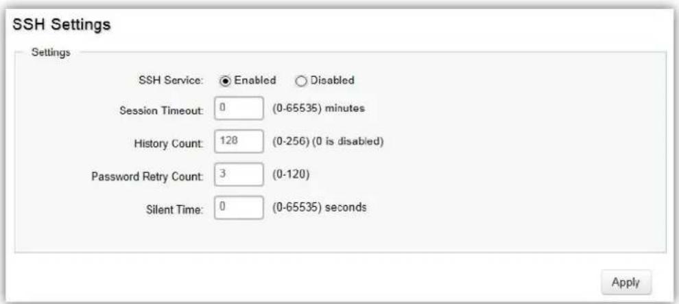
| Telnet Service | Select whether the Telnet service is Enabled or Disabled. It is enabled by default. |
| Session Timeout | Enter the amount of me that elapses before the Telnet service is med out. The default is 5 minutes. The range is from 0 to 65535 minutes. |
| History Count | Enter the entry number for history of Telnet service. The default is 128. The range is from 0 to 256. |
| Password Retry Count | Enter the number of password request send to Telnet service. The default is 3. The range is from 0 to 120. |
| Silent Time | Enter the silent me for Telnet service. The range is from 0 to 65535 seconds. |
Click Apply to update the system sengs.
Console Settings
From here, you can congregate the Console service sengs for the Switch.
Console Settings
Settings
Session Timeout:

(0-65535) minutes
History Count

(0-256) (0 is disabled)
Password Retry Count:

(0-120)
Silent Time

(0-65535) seconds
Apply
| Session Timeout | Enter the amount of me that elapses before Console service is med out. The default is 5 minutes. The range is from 0 to 65535 minutes. |
| History Count | Enter the entry number for history of Console service. The default is 128. The range is from 0 to 256. |
| Password Retry Count | Enter the number of password requests to send to the Console service. The default is 3. The range is from 0 to 120. |
| Silent Time | Enter the silent me for Console service. The range is from 0 to 65535 seconds. |
Click Apply to update the system sengs.
Port Security
Network security can be increased by liming access on a specific port to users with specific MAC addresses. Port Security prevents unauthorized device to the Switch prior to stopping auto-learning processing.
Port Security
| Port | State | Max MAC Address | |
| □ | Disabled | 256 | |
| □ | 1 | Disabled | 256 |
| □ | 2 | Disabled | 256 |
| □ | 3 | Disabled | 256 |
| □ | 4 | Disabled | 256 |
| □ | 5 | Disabled | 256 |
| □ | 6 | Disabled | 256 |
| □ | 7 | Disabled | 256 |
| □ | 8 | Disabled | 256 |
| □ | 9 | Disabled | 256 |
| □ | 10 | Disabled | 256 |
| □ | 11 | Disabled | 256 |
| □ | 12 | Disabled | 256 |
| Max MAC Address | Enter the maximum number of MAC addresses that can be learned on the port. The range is from 1 to 256. |
| Port | Displays the port for which the port security is dened. |
| State | Select Enabled or Disabled for the port security feature for the selected port. |
Click Apply to update the system sengs.
Port Isolation
Port Isolaon feature provides L2 isolaon between ports within the same broadcast domain. When enabled, Isolated ports can forward trac to Not Isolated ports, but not to other Isolated ports. Not Isolated ports can send trafc to any port; whether Isolated or Not Isolated. The default seng is Not Isolated.
| Port Isolation | ||
| Port | Status | |
| □ | Not Isolated | |
| □ | 1 | Not Isolated |
| □ | 2 | Not Isolated |
| □ | 3 | Not Isolated |
| □ | 4 | Not Isolated |
| □ | 5 | Not Isolated |
| □ | 6 | Not Isolated |
| □ | 7 | Not Isolated |
| □ | 8 | Not Isolated |
| □ | 9 | Not Isolated |
| □ | 10 | Not Isolated |
Click Apply to update the system sengs.
DoS
DoS (Denial of Service) is used for classifying and blocking specific types of DoS aacks. From here, you can congure the Switch to monitor and block dierent types of aacks.
Global Settings
On this page, the user can enable or disable the prevenon of dierent types of DoS aacks. When enabled, the switch will drop the packets matching the types of DoS aack detected.

Click Apply to update the system sengs.
Port Settings
From here you can congregate the Port Sengs for DoS for the Switch. Select from the drop down list whether you wish to enable or disable DoS protecon for the Switch.
| Port Settings | ||
| Port | DoS Protection | |
| □ | Disabled | |
| □ | 1 | Disabled |
| □ | 2 | Disabled |
| □ | 3 | Disabled |
| □ | 4 | Disabled |
| □ | 5 | Disabled |
| □ | 6 | Disabled |
| □ | 7 | Disabled |
| □ | 8 | Disabled |
| □ | 9 | Disabled |
| Port | Displays the port for which the DoS protecon is dened. |
| DoS Protecon | Select Enabled or Disabled for the DoS protecon feature for the selected port. |
Click Apply to update the system sengs.
Monitoring
Port Statistics
The Port Stascs page displays a summary of all port trac stascs.
| Port Statistics | |||||||||||||
| Port | RXByte | RXUcast | RXNUcast | RXDiscard | TXByte | TXUcast | TXNUcast | TXDiscard | RXMcast | RXBcast | TXMcast | TXBcast | |
| □ | |||||||||||||
| □ | 1 | 68425444 | 266869 | 39943 | 0 | 1608175557 | 384133 | 11968890 | 0 | 32978 | 6965 | 3299502 | 8669388 |
| □ | 2 | 1183982561 | 4423669 | 581931 | 0 | 1202944962 | 6789468 | 64236755 | 0 | 218709 | 373222 | 17637471 | 46599284 |
| □ | 3 | 0 | 0 | 0 | 0 | 0 | 0 | 0 | 0 | 0 | 0 | 0 | 0 |
| □ | 4 | 0 | 0 | 0 | 0 | 0 | 0 | 0 | 0 | 0 | 0 | 0 | 0 |
| □ | 5 | 0 | 0 | 0 | 0 | 0 | 0 | 0 | 0 | 0 | 0 | 0 | 0 |
| □ | 6 | 14543 | 0 | 113 | 0 | 652787142 | 740821 | 4367228 | 10 | 51 | 62 | 1022949 | 3344279 |
| □ | 7 | 1422341998 | 5321905 | 17279 | 0 | 3721828038 | 5893463 | 82980852 | 0 | 4190 | 13089 | 21025720 | 61955132 |
| □ | 8 | 1258800280 | 5333578 | 69426 | 0 | 1916129700 | 6792252 | 82929143 | 0 | 63296 | 6130 | 20966739 | 61962404 |
| □ | 9 | 395175380 | 5716714 | 237502 | 0 | 355120309 | 5674469 | 82760755 | 0 | 111212 | 126290 | 20918692 | 61842063 |
| □ | 10 | 1579406332 | 28707090 | 82155864 | 0 | 769244081 | 26430416 | 963478 | 0 | 20738436 | 61417428 | 412219 | 551259 |
| Port | Displays the port for which stascs are displayed. |
| RXByte | Displays the number of all packets received on the port. |
| RXUcast | Displays the number of unicast packets received on the port. |
| RXNUcast | Displays the number of unicast packets received on the port. |
| RXDiscard | Displays the number of received packets discarded on the port. |
| TXByte | Displays the number of all packets transmied on the port. |
| TXUcast | Displays the number of unicast packets transmied on port. |
| TXNUcast | Displays the number of unicast packets transmied on the port. |
| TXDiscard | Displays the number of transmied packets discarded on the port. |
| RXMcast | Displays the number of mulcast packets received on the port. |
| RXBcast | Displays the number of broadcast packets received on the port. |
| TXMcast | Displays the number of mulcast packets transmied on the port. |
| TXBcast | Displays the number of broadcast packets transmied on the port. |
RMON
Remote Network Monitoring, or RMON is used for support monitoring and protocol analysis of LANs by enabling various network monitors and console systems to exchange network monitoring data through the Switch.
Event List
The Event List denes RMON events on the Switch.
| Event List | |||||
| Index | Event Type | Community | Description | Last Time Sent | Owner |
| 1 ~ 65535 | Log | private | char : 0 ~ 127 | char : 0 ~ 32 | |
| Index | Enter the entry number for event. |
| Event Type | Select the event type.Log: The event is a log entry.SNMP Trap: The event is a trap.Log & Trap: The event is both a log entry and a trap. |
| Community | Enter the community to which the event belongs. |
| Descripon | Displays the number of good broadcast packets received on the interface. |
| Last Time Sent | Displays the me that event occurred. |
| Owner | Enter the switch that dened the event. |
Click the Apply button

to accept the changes or the Cancel buon

to discard them.
Event Log Table
From here, you can view specific event logs for the Switch. Choose an event log you wish to view from the drop down list.

Alarm List
You can congregate network alarms to occur when a network problem is detected. Choose your preferences for the alarm from the drop down boxes.

| Index | Enter the entry number for the Alarm List. |
| Sample Port | Select the port from which the alarm samples were taken. |
| Sample Variable | Select the variable of samples for the specied alarm sample. |
| Sample Interval | Enter the alarm interval me. |
| Sample Type | Select the sampling method for the selected variable and comparing the value against the thresholds.Absolute: Compares the values with the thresholds at the end of the sampling interval.Delta: Subtracts the last sampled value from the current value. |
| Rising Threshold | Enter the rising number that triggers the rising threshold alarm. |
| Falling Threshold | Enter the falling number that triggers the falling threshold alarm. |
| Rising Event | Enter the event number by the falling alarm are reported. |
| Falling Event | Enter the event number by the falling alarms are reported. |
| Owner | Enter the Switch that dened the alarm. |
Click the Apply button √ to accept the changes or the Cancel buon ✗ to discard them.
History List

| Index | Enter the entry number for the History List. |
| Sample Port | Select the port from which the history samples were taken. |
| Bucket Requested | Enter the number of samples to be saved. The range is from 1 to 50. |
| Interval | Enter the me that samples are taken from the ports. The eld range is from 1 to 3600. |
| Owner | Enter the RMON user that requested the RMON informaon. The range is from 0 to 32 characters. |
Click the Apply button √ to accept the changes or the Cancel button ✗ to discard them.
History Log Table
From here, you can view the History Index for history logs on the Switch. Select a history index to view from the drop down box.
History Log Table
Select History Index:
none

Refresh
Statistics
From here, you can view all the RMON stascs of the Switch.
| Port | Drop Events | Octets | Pkts | Broadcast Pkts | Multicast Pkts | CRC Align Errors | Under Size Pkts | Over Size Pkts | Fragments | Jabbers | Collisions | Pkts 64 Octets | Pkts 65 to 127 Octets | Pkts 128 to 255 Octets | Pkts 256 to 511 Octets | Pkts 512 to 1023 Octets | Pkts 1024 to 1518 Octets | |
| □ | ||||||||||||||||||
| □ | 1 | 0 | 68425444 | 296812 | 6965 | 32978 | 0 | 0 | 0 | 0 | 0 | 0 | 119763 | 82197 | 32611 | 13992 | 40047 | 8002 |
| □ | 2 | 0 | 1183991729 | 5015632 | 373236 | 218717 | 0 | 0 | 0 | 0 | 0 | 0 | 457631 | 3352136 | 389564 | 147102 | 303989 | 365210 |
| □ | 3 | 0 | 0 | 0 | 0 | 0 | 0 | 0 | 0 | 0 | 0 | 0 | 0 | 0 | 0 | 0 | 0 | 0 |
| □ | 4 | 0 | 0 | 0 | 0 | 0 | 0 | 0 | 0 | 0 | 0 | 0 | 0 | 0 | 0 | 0 | 0 | 0 |
| □ | 5 | 0 | 0 | 0 | 0 | 0 | 0 | 0 | 0 | 0 | 0 | 0 | 0 | 0 | 0 | 0 | 0 | 0 |
| □ | 6 | 0 | 14543 | 113 | 62 | 51 | 0 | 169 | 0 | 0 | 0 | 195 | 20 | 60 | 28 | 5 | 0 | 0 |
| □ | 7 | 0 | 1422364322 | 5339283 | 13089 | 4190 | 42 | 4 | 0 | 0 | 5 | 0 | 1546901 | 2153386 | 412948 | 577706 | 86773 | 561560 |
| □ | 8 | 0 | 1258810916 | 5403047 | 6130 | 63299 | 0 | 0 | 0 | 0 | 0 | 0 | 1630174 | 2170577 | 344589 | 454608 | 486857 | 315842 |
| □ | 9 | 0 | 395187668 | 5954372 | 126364 | 111212 | 0 | 0 | 0 | 0 | 0 | 0 | 355586 | 2207222 | 259740 | 116842 | 75385 | 2939597 |
| □ | 10 | 0 | 1579921264 | 110866964 | 61419749 | 20739682 | 0 | 0 | 0 | 0 | 0 | 0 | 34970962 | 47545335 | 14504915 | 5037080 | 1427176 | 7381496 |
| □ | 11 | 0 | 0 | 0 | 0 | 0 | 0 | 0 | 0 | 0 | 0 | 0 | 0 | 0 | 0 | 0 | 0 | 0 |
| □ | 12 | 0 | 0 | 0 | 0 | 0 | 0 | 0 | 0 | 0 | 0 | 0 | 0 | 0 | 0 | 0 | 0 | 0 |
| Port | Indicates the specic port for which RMON stascs are displayed. |
| Drop Events | Displays the number of dropped events that have occurred on the port. |
| Octets | Displays the number of octets received on the port. |
| Pkts | Displays the number of packets received on the port. |
| Broadcast Pkts | Displays the number of good broadcast packets received on the port. This number does not include Mulcast packets. |
| Mulcast Pkts | Displays the number of good Mulcast packets received on the port. |
| CRC & Align Errors | Displays the number of CRC and Align errors that have occurred on the port. |
| Undersize Pkts | Displays the number of undersized packets (less than 64 octets) received on the port. |
| Oversize Pkts | Displays the number of oversized packets (over 1518 octets) received on the port. |
| Fragments | Displays the number of fragments received on the port. |
| Jabbers | Displays the total number of received packets that were longer than 1518 octets. |
| Collisions | Displays the number of collisions received on the port. |
| Pkts of 64 Octets | Displays the number of 64-byte frames received on the port. |
| Pkts of 65 to 127 Octets | Displays the number of 65 to 127 byte packets received on the port. |
| Pkts of 128 to 255 Octets | Displays the number of 128 to 255 byte packets received on the port. |
| Pkts of 256 to 511 Octets | Displays the number of 256 to 511 byte packets received on the port. |
| Pkts of 512 to 1023 Octets | Displays the number of 512 to 1023 byte packets received on the port. |
| Pkts of 1024 to 1518 Octets | Displays the number of 1024 to 1518 byte packets received on port. |
Log
The Syslog protocol allows devices to send event nocaon messages in response to events, faults, or errors occurring on the plaorm as well as changes in conguraon or other occurrences across an IP network to syslog servers. It then collects the event messages, providing powerful support for users to monitor network operaon and diagnose malfuncons. A Syslog-enabled device can generate a syslog message and send it to a Syslog server.
Syslog is dened in RFC 3164. The RFC denes the packet format, content, and system log related informaon of Syslog messages. Each Syslog message has a facility and severity level. The Syslog facility idenes a le in the Syslog server. Refer to the documentaon of your Syslog program for details. The following table describes the Syslog severity levels.
| Code | Severity | Descripon | General Descripon |
| 0 | EMERG | System is unusable. | A "panic" condion usually aecng mulple apps/servers/sites. At this level it would usually nofy all tech sta on call. |
| 1 | ALERT | Acon must be taken immediately. | Should be corrected immediately, therefore nofy sta who can x the problem. An example would be the loss of a primary ISP conncon. |
| 2 | CRIT | Crical condions. | Should be corrected immediately, but indicates failure in a secondary system, an example is a loss of a backup ISP conncon. |
| 3 | ERROR | Error condions. | Non-urgent failures, these should be relayed to developers or admins; each item must be resolved within a given me. |
| 4 | WARNING | Warning condions. | Warning messages, not an error, but indicaon that an error will occur if acon is not taken, e.g. le system 85% full - each item must be resolved within a given me. |
| 5 | NOTICE | Normal but significant condion. | Events that are unusual but not error condions - might be summarized in an email to developers or admins to spot potenal problems - no immediate acon required. |
| 6 | INFO | Informaonal messages | Normal operaonal messages - may be harvested for reporng, measuring throughput, etc. - no acon required. |
Global Settings
From here, you can Enable or Disable the log sengs for the Switch.

Click Apply to update the system sengs.
Local Logging
The System Log is designed to monitor the operaon of the Switch by recording the event messages it generates during normal operaon. These events may provide vital informaon about system acvity that can help in the idencaon and soluons of system problems.
The Switch supports log output to two direcons: Flash and RAM. The informaon stored in the system's RAM log will be lost aer the Switch is rebooted or powered o, whereas the informaon stored in the system's Flash will be kept eecve even if the Switch is rebooted or powered o. The log has a xed capacity; at a certain level, the EWS Switch will start deleng the oldest entries to make room for the newest.
Local Logging
| Target | EMERG | ALERT | CRIT | ERROR | WARNING | NOTICE | INFO | DEBUG |
| RAM | Yes | Yes | Yes | Yes | Yes | Yes | Yes | Yes |
| Flash | Yes | Yes | Yes | Yes | Yes | Yes | Yes | Yes |
Click the Apply button

to accept the changes or the Cancel buon

to discard them.
Remote Logging
The internal log of the EWS Switch has a xed capacity; at a certain level, the EWS Switch will start deleng the oldest entries to make room for the newest. If you want a permanent record of all logging advies, you can set up your syslog server to receive log contents from the EWS Switch. Use this page to direct all logging to the syslog server. Click the Add buon, dene your syslog server, and select the severity level of events you wish to log.

Click the Apply button √ to accept the changes or the Cancel buon ✗ to discard them.
Event Logs
This page displays the most recent records in the Switch's internal log. Log entries are listed in reverse chronological order (with the latest logs at the top of the list). Click a column header to sort the contents by that category.

Display logs in
- RAM: The informaon stored in the system's RAM log will be lost aer the Switch is rebooted or powered o
- Flash: The informaon stored in the system's Flash will be kept eecve even if the Switch is rebooted or powered o.
Type
- Switch: Display switch related logs.
• All: Display logs for both controller and switch.
Export: Click Export buon to export the current buered log to a .txt le.
Clear: Click Clear buon to clear the buered log in the system's memory.
Diagnostics
Cable Diagnostics
Cable Diagnoscs helps you to detect whether your cable has connectivity problems provides informaon about where errors have occurred in the cable. The tests use Time Domain Reectometry (TDR) technology to test the quality of a copper cable aached to a port. TDR detects a cable fault by sending a signal through the cable and reading the signal that is reected back. All or part of the signal is reected back either by cable defects or by the end of the cable when an issue is present. Cables are tested when the ports are in the down state, with the exception of the cable length test.

To verify accuracy of the test, it is recommended that you run multiple tests in case of test fault or user error.
Click Test to perform the cable tests for the selected port.
Ping Test
The Packet INternet Groper (Ping)Test allows you to verify connecvity to remote hosts. The Ping test operates by sending Internet Control Message Protocol (ICMP) request packets to the tested host and waits for an ICMP response. In the process it measures the me from transmission to recepon and records any packet loss. Send a ping request to a specied IPv4 address. Check whether the Switch can communicate with a parcular network host before tesng.

You can vary the test parameters by entering the data in the appropriate boxes. To verify accuracy of the test, it is recommended that you run multiple tests in case of a test fault or user error.
| IP Address | Enter the IP address or the host name of the staon you want the Switch to ping to. |
| Count | Enter the number of ping to send. The range is from 1 to 5 and the default is 4. |
| Interval | Enter the number of seconds between pings sent. The range is from 1 to 5 and the default is 1. |
| Size | Enter the size of ping packet to send. The range is from 8 to 5120 and the default is 56. |
| Result | Displays the ping test results. |
Click Test to perform the ping test.
IPv6 Ping Test
Send a ping request to a specied IPv6 address. Check whether the Switch can communicate with a parcular network host before tesng.
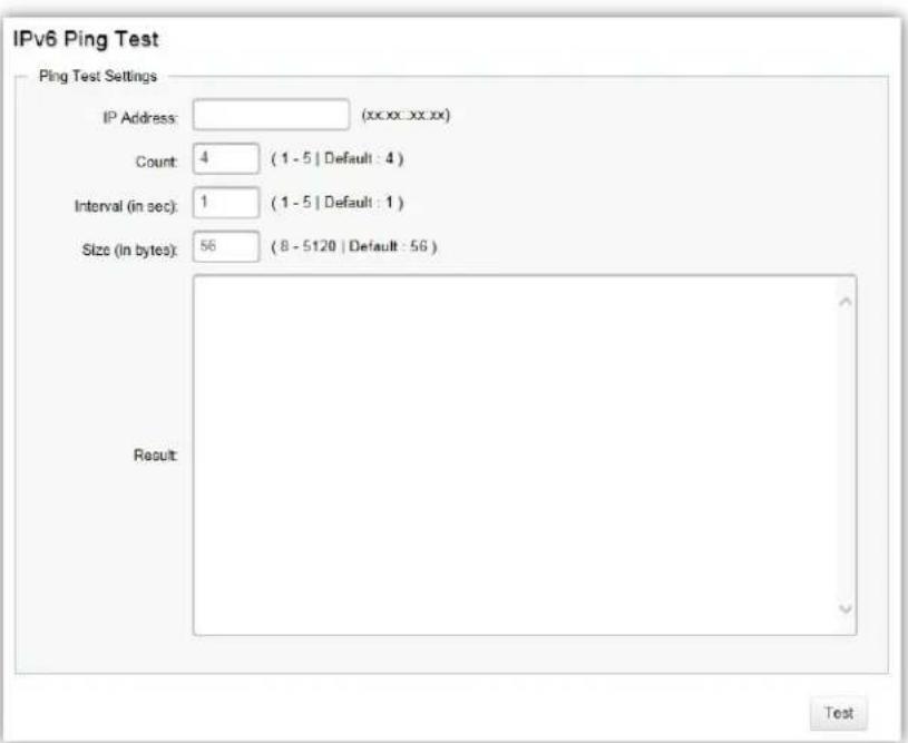
You can vary the test parameters by entering the data in the appropriate boxes. To verify accuracy of the test, it is recommended that you run mulple tests in case of a test fault or user error.
| IP Address | Enter the IPv6 address or the host name of the staon you want the Switch to ping to. |
| Count | Enter the number of ping to send. The range is from 1 to 5 and the default is 4. |
| Interval | Enter the number of seconds between pings sent. The range is from 1 to 5 and the default is 1. |
| Size | Enter the size of ping packet to send. The range is from 8 to 5120 and the default is 56. |
| Result | Displays the ping test results. |
Click Test to perform the ping test.
Trace Route
The traceroute feature is used to discover the routes that packets take when traveling to their desnaon. It will list all the routers it passes through unl it reaches its desnaon, or fails to reach the desnaon and is discarded. In tesng, it will tell you how long each hop from router to router takes via the trip me of the packets it sends and receives from each successive host in the route.
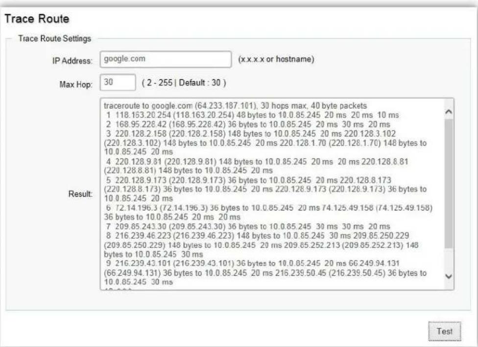
| IP Address | Enter the IP address or the host name of the staon you wish the Switch to ping to. |
| Max Hop | Enter the maximum number of hops. The range is from 2 to 255 and the default is 30. |
| Result | Displays the trace route results. |
Click Test to initiate the trace route.
Maintenance
Maintenance funcons are available from the maintenance bar located on the upper right corner of the user interface. Maintenance funcons include: saving conguraon sengs, upgrading rmware, reseng the conguraon to factory default standards, reboong the device, and logging out of the interface. The following represents the Maintenance menu bar.

Configuration Manager
The File Management feature is used for saving your current conguraon to a le on your computer or a TFTP server, or to restore previously saved conguraon sengs to the Switch using a conguraon le from your local drive or TFTP server.

Click Apply to download conguraon sengs to your computer or a TFTP server, or to upload previously saved conguraon le to the system.
Firmware Upgrade


WARNING
Backup your conguraon before upgrading to prevent loss of sengs informaon.

NOTE: The upgrade process may require a few minutes to complete. It is advised to clear your browser cache aer upgrading your rmware.
Appendix
Appendix A - Federal Communication Commission Interference Statement
This equipment has been tested and found to comply with the limits for a Class B digital device, pursuant to Part 15 of the FCC Rules. These limits are designed to provide reasonable protecon against harmful interference in a residential installaon. This equipment generates, uses, and can radiate radio frequency energy and, if not installed and used in accordance with the instrucons, may cause harmful interference to radio communicaons. However, there is no guarantee that interference will not occur in a parcular installaon. If this equipment does cause harmful interference to radio or television recepon, which can be determined by turning the equipment o and on, the user is encouraged to try to correct the interference by one of the following measures:
Reorient or relocate the receiving antenna.
Increase the separaon between the equipment and receiver.
Connect the equipment into an outlet on a circuit dierent from that to which the receiver is connected.
Consult the dealer or an experienced radio/TV technician for help.

WARNING!
Any changes or modicaons not expressly approved by the party responsible for compliance could void the user's authority to operate this equipment.
This device complies with Part 15 of the FCC Rules. Operaon is subject to the following two conditions: (1) This device may not cause harmful interference, and (2) this device must accept any interference received, including interference that may cause undesired operaon.
Radiation Exposure Statement

This equipment complies with FCC radiaon exposure limits set forth for an uncontrolled environment. This equipment should be installed and operated with a minimum distance of 23 cm between the radiator & your body.
Appendix B - IC Interference Statement
Industry Canada Statement
This device complies with RSS-210 of the Industry Canada Rules. Operaon is subject to the following two conditions: (1) This device may not cause harmful interference, and (2) this device must accept any interference received, including interference that may cause undesired operaon.
Radiation Exposure Statement
This equipment complies with IC radiaon exposure limits set forth for an uncontrolled environment. This equipment should be installed and operated with a minimum distance of 20cm between the radiator & your body.
Europe - EU Declaration of Conformity
This device complies with the essenal requirements of the R&TTE Direcve 1999/5/EC. The following test methods have been applied in order to prove presumption of conformity with the essenal requirements of the R&TTE Direcve 1999/5/EC:
- EN60950-1
Safety of Informaon Technology Equipment
EN50385
Generic standard to demonstrate the compliance of electronic and electrical apparatus with the basic restricons related to human exposure to electromagnec elds (0 Hz - 300 GHz)
• EN 300 328
Electromagnec compatibility and Radio spectrum Maers (ERM); Wideband Transmission systems; Data transmission equipment operang in the 2,4 GHz ISM band and using spread spectrum modulaon techniques; Harmonized EN covering essenal requirements under arcle 3.2 of the R&TTE Direcve
• EN 301 893
Broadband Radio Access Networks (BRAN); 5 GHz high performance RLAN; Harmonized EN covering essenal requirements of arcle 3.2 of the R&TTE Direcve
• EN 301 489-1
Electromagnec compatibility and Radio Spectrum Maers (ERM); ElectroMagnec Compatibility (EMC) standard for radio equipment and services; Part 1: Common technical requirements
• EN 301 489-17
Electromagnec compatibility and Radio spectrum Maers (ERM); ElectroMagnec Compatibility (EMC) standard for radio equipment and services; Part 17: Specific conditions for 2,4 GHz wideband transmission systems and 5 GHz high performance RLAN equipment
This device is a 5GHz wideband transmission system (transceiver), intended for use in all EU member states and EFTA countries, except in France and Italy where restrictive use applies.
In Italy the end-user should apply for a license at the naonal spectrum authorities in order to obtain authorizaon to use the device for seng up outdoor radio links and/or for supplying public access to telecommunications and/or network services.
This device may not be used for seng up outdoor radio links in France and in some areas the RF output power may be limited to 10 mW EIRP in the frequency range of 2454 – 2483.5 MHz. For detailed informaon the end-user should contact the naonal spectrum authority in France.
CE0560①
| Česky [Czech] | [Jméno výrobce] mto prohlašuje, že tento [typ zařízení] je ve shodě se základními požadavky a dalšími příslušnými ustanoveními směrnice 1999/5/ES. |
| Dansk [Danish] | Undertegnede [fabrikantens navn] erklæ rer herved, at følgende udstyr [udstyrets typebetegnelse] overholder de væ sentlige krav og øvrige relevante krav i direkv 1999/5/EF. |
| Deutsch [German] | Hiermit erklärt [Name des Herstellers], dass sich das Gerät [Gerätetyp] in Ü bereinsmmung mit den grundlegenden Anforderungen und den übrigen einschlägigen Besimmungen der Richtlinie 1999/5/EG bendet. |
| Ees [Estonian] | Käesolevaga kinnitab [tootja nimi = name of manufacturer] seadme [seadme tüüp = type of equipment] vastavust direkivi 1999/5/EÜ põhinõuetele ja nimetatud direkivist tulenevatele teistele asjakohastele sätetele. |
| English | Hereby, [name of manufacturer], declares that this [type of equipment] is in compliance with the essenal requirements and other relevant provisions of Direcve 1999/5/EC. |
| Español [Spanish] | Por medio de la presente [nombre del fabricante] declara que el [clase de equipo] cumple con los requisitos esenciales y cualesquiera otras disposiciones aplicables o exigibles de la Direcva 1999/5/CE. |
| Ελληνική [Greek] | ME THN ΠΑΡΟΥΣΑ [name of manufacturer] ΔΗΛΩΝΕΙ ΟΤΙ [type of equipment] ΣΥΜΜΟΡΦΩΝΕΤΑΙ ΠΡΟΣ ΤΙΣ ΟΥΣΙΩΔΕΙΣ ΑΠΑΙΤΗΣΕΙΣ ΚΑΙ ΤΙΣ ΛΟΙΠΕΣ ΣΧΕΤΙΚΕΣ ΔΙΑΤΑΞΕΙΣ ΤΗΣ ΟΔΗΓΙΑΣ 1999/5/ΕΚ. |
| Français [French] | Par la présente [nom du fabricant] déclare que l’appareil [type d’appareil] est conforme aux exigences essenelles et aux autres disposions pertinentes de la direcve 1999/5/CE. |
| Italiano [Italian] | Con la presente [nome del costruore] dichiara che questo [po di apparecchio] è conforme ai requisi essenziali ed alle altre disposizioni pernen stabilite dalla direva 1999/5/CE. |
| Latviski [Latvian] | Ar šo [name of manufacturer / izgatavotāja nosaukums] deklarē, ka [type of equipment / iekārtas ps] atbilst Direkvas 1999/ 5/EK būskajām prasībām un ciem ar to saistajiem noteikumiem. |
| Lietuvių [Lithuanian] | Šiuo [manufacturer name] deklaruoja, kad šis [equipment type] anka esminius reikalavimus ir kitas 1999/5/EB Direktyvos nuostatas. |
| Nederlands [Dutch] | Hierbij verklaart [naam van de fabrikant] dat het toestel [type van toestel] in overeenstemming is met de essenële eisen en de andere relevante bepalingen van richtlijn 1999/5/EG. |
| Mal [Maltese] | Hawnhekk, [isem tal-manifaur], jiddikjara li dan [il-mudel tal-prodo] jikkonforma mal-ħgijiet essenzjali u ma provvedimen oħrajn relevan li hemm d-Dirretva 1999/5/EC. |
| Magyar [Hungarian] | Alulíro, [gyártó neve] nyilatkozom, hogy a [... pus] megfelel a vonatkozó alapvető követelményeknek és az 1999/5/EC irányelv egyéb előírásainak. |
| Polski [Polish] | Niniejszym [nazwa producenta] oświadcza, że [nazwa wyrobu] jest zgodny z zasadniczymi wymogami oraz pozostałymi stosownymi postanowieniami Dyrektywy 1999/5/EC. |
| Português [Portuguese] | [Nome do fabricante] declara que este [po de equipamento] está conforme com os requisitos essenciais e outras disposições da Direcva 1999/5/CE. |
| Slovensko [Slovenian] | [lme proizvajalca] izjavlja, da je ta [p opreme] v skladu z bistvenimi zahtevami in ostalimi relevantnimi določili direkve 1999/5/ES. |
| Slovensky [Slovak] | [Meno výrobcu] týmto vyhlasuje, že [typ zariadenia] spĺňa základné požiadavky a všetky príslušné ustanovenia Smernice 1999/5/ES. |
| Suomi [Finnish] | [Valmistaja = manufacturer] vakuuaa täten eä [type of equipment = laieen tyyppimerkintä] tyyppinen laite on direkivin 1999/5/EY oleellisten vaamusten ja sitä koskevien direkivin muiden ehtojen mukainen. |
| Svenska [Swedish] | Härmed intygar [företag] a denna [utrustningstyp] står l överensstämmelse med de väsentliga egenskapskrav och övriga relevanta bestämmelser som framgår av direkv 1999/5/EG. |
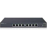


- IMPORTANT
- Table of Contents
- Product Overview....7
- Getting Started....14
- Software Features....18
- Management....140
- ACL 152
- QoS....163
- Security 171
- Monitoring....184
- Diagnoscs....195
- Appendix 201
- Chapter 1
- Product Overview
- Introduction
- Key Features
- System Requirements
- Package Contents
- Technical Specifications
- Software Features
- Wireless Management Features
- L2 Features
- VLAN
- QoS
- Access Control List (ACL)
- Security
- Monitoring
- Management
- Diagnosc
- MIB/RFC Standards
- Environment Specifications
- Operang Temperature
- Humidity (Non-condensing)
- Physical Specifications
- Dimensions (W x D x H)
- Chapter 2
- Getting Started
- Installing the Switch
- Management Interface
- Management Interface Default Values
- Connecting the Switch to a Network
- Discovery in a Network with a DHCP server
- Chapter 3
- Using the Switch
- Wireless Controller Features
- Managing EWS Access Points
- Device Management
- Summary
- Dashboard
- Controller State
- System Informaon
- Access Points
- Managing Access Points
- Refresh Countdown Timer
- AP(s) Detected List
- Remove AP
- Reboot AP
- Search Bar
- Status
- Model Name
- MAC Address
- Device Name
- IP Address
- Firmware Version
- Last Update
- Group
- Column Filter
- Access Point Settings
- General Sengs
- WLAN Sengs - 2.4GHz/5GHz
- SSID Cong
- Advanced Sengs
- Manual IP Sengs
- Automac DHCP Server Sengs
- AP Groups
- Creang a New AP Group
- Delete 4%
- Delete
- Add Buon
- Edit Buon
- Delete Buon
- Access Control
- Blocking a Specific Client Device
- Unblocking a Previously Blocked Client Device
- Blocked Clients
- Apply Buon
- Wireless Services
- Background Scanning
- Auto TX Power
- Monitor
- Active Clients
- Kick Client
- Ban Client
- Rogue AP Detection
- System Log
- Global Settings
- Local Logging
- Severity Level
- Remote Logging
- IP/Hostname
- Server Port
- Facility
- Event Logs
- Display logs in
- Type:
- Export
- Clear
- Email Alert
- Alert Settings
- Mail Informaon Seng
- Event Binding
- Visualization
- Topology View
- Navigang Tips
- Search
- Map View
- Floor View
- Floorplan Image
- Status Dashboard
- Floorplan View
- Sengs
- AP Info
- RF Coverage
- Statistics
- Wireless Clients
- Real Time Throughput
- Hotspot Services
- Captive Portal
- Guest Account
- Maintenance
- Schedule Tasks
- Troubleshooting
- Choosing an Access Point to Diagnose
- Bulk Upgrade
- One-Click Update
- Update List
- Update Settings
- Automacally Check for Updates
- Update Server
- Check updates from specific server
- Example:
- SSL Certificate
- Check Codes
- Migration to ezMaster
- Ethernet Switch Features
- System
- IP Settings
- IPv4
- Important:
- IPv6
- System Time
- To congure date/me through SNMP:
- To congure date/me manually:
- Port Settings
- PoE
- Power Budget
- PoE Port Settings
- EEE
- L2 Feature
- Link Aggregation
- Port Trunking
- LACP Settings
- LACP Timeout
- Mirror Settings
- Note
- STP
- Root Bridge
- CIST Instance Settings
- CIST Port Settings
- MST Instance Settings
- MST Port Settings
- MAC Address Table
- Static MAC Address
- Dynamic MAC Address
- LLDP
- Local Device
- Remote Device
- IGMP Snooping
- VLAN Settings
- Querier Settings
- Group List
- Router Settings
- MLD Snooping
- Jumbo Frame
- 802.1Q
- PVID
- Management VLAN
- Voice VLAN
- OUI Settings
- System Information
- User Management
- Dual Image
- SNMP
- View List
- Community List
- User List
- Trap Settings
- ACL
- MAC ACL
- MAC ACE
- IPv4 ACL
- IPv4 ACE
- IPv6 ACL
- IPv6 ACE
- ACL Binding
- CoS Mapping
- DSCP Mapping
- Bandwidth Control
- Storm Control
- 802.1x
- Authenticated Host
- RADIUS Server
- Access
- HTTP(S) Settings
- Telnet Settings
- SSH Settings
- Console Settings
- Port Security
- Port Isolation
- DoS
- Port Statistics
- RMON
- Event List
- Event Log Table
- Alarm List
- History List
- History Log Table
- Log
- Type
- Diagnostics
- Cable Diagnostics
- Ping Test
- IPv6 Ping Test
- Trace Route
- Configuration Manager
- Firmware Upgrade
- WARNING
- Appendix
- Appendix A - Federal Communication Commission Interference Statement
- WARNING!
- Radiation Exposure Statement
- Appendix B - IC Interference Statement
- Industry Canada Statement
- Europe - EU Declaration of Conformity
- CE0560①
Brand : ENGENIUS
Model : EWS1200-28TFP
Category : Network switch