
CACR-KL2-40-W2000 - Electric resistance Festo - Free user manual and instructions
Find the device manual for free CACR-KL2-40-W2000 Festo in PDF.


| Product Type | Pneumatic Cylinder (Double-acting) |
| Model | CACR-KL2-40-W2000 |
| Brand | Festo |
| Bore Diameter | 40 mm |
| Stroke Length | 2000 mm |
| Operating Pressure | 0.6 to 10 bar |
| Operating Temperature | -20 to 80 °C |
| Port Size | G1/4 |
| Cushioning | Adjustable pneumatic cushioning at both ends |
| Piston Rod Material | Stainless steel |
| Seals Material | Polyurethane (PUR) |
| Mounting Type | Through-hole and threaded holes |
| Weight | Approx. 2.5 kg |
| Maximum Speed | 1 m/s |
| Medium | Compressed air (filtered, lubricated or non-lubricated) |
| Standards | ISO 15552 |
| Protection Class | IP40 |
| Maintenance | Check seals and lubrication periodically; clean with mild solvent |
| Safety | Do not exceed max pressure; use with appropriate safety valves |
| Spare Parts | Seal kits, piston rod, cushions available from Festo |
Frequently Asked Questions - CACR-KL2-40-W2000 Festo
User questions about CACR-KL2-40-W2000 Festo
0 question about this device. Answer the ones you know or ask your own.
Ask a new question about this device
Download the instructions for your Electric resistance in PDF format for free! Find your manual CACR-KL2-40-W2000 - Festo and take your electronic device back in hand. On this page are published all the documents necessary for the use of your device. CACR-KL2-40-W2000 by Festo.
USER MANUAL CACR-KL2-40-W2000 Festo
Brake resistor - BWD500160K04LIP65FE CACR-KL2-40-W2000
*Sc




Description:
Short-circuit-proof, self-protecting ^1) resistor unit for operation on converters (brake transistors) consisting of 4 resistor modules in anodized aluminium casings. Protection class according to IP65 ^2) , interconnected by spring-type terminals. For detailed measurements, see technical drawing (on request).
| Nominal capacity (W) | Dimensions LxBxH (mm) | Resistance values (Ohm) |
| 800 (2000 at ED = 35%, _A = 20°C) | 216 x 211 x 91,5 | 40 |
Technical data:
| Parameters | Symbol | Value | Unit | Conditions |
| Tolerance | ±5 | % | Room temperature | |
| Weight | m | approx 3,4 | kg | |
| Connection data terminalConductor cross-section | Max. | 6 mm | ^2 | Depending on the design of the cable cross-section |
| Storing temperature | _S | -25 ... +85 | °C |
Limit values ( _A = 20^ , if nothing else is stated):
| Parameters | Symbol | Value | Unit | Conditions |
| Max. permissible operating voltage | U_B | ≤ 700 AC≤ 1000 DC | V | considering "self-protection" 1) |
| U_B | ≤ 600 AC#*≤ 850 DC* | V | considering CSA# and UL* | |
| Energy consumption | E | 7,515 | kJ | with 1,2s (1% ED)with 7,2s (6% ED) |
| Insulation voltage | U_ISO | ≥ 4000 | V | AC; f = 50 Hz; t = 1 s |
| Max. permissible casing temperature | _C | ≤ 250 | °C | free convection |
| Temperature coefficient | TK | 20 ... 100 | 10^-6/K | |
| Insulation resistance | R_ISO | ≥ 100 | MΩ | U_MEAS = 1000 VDC |
| Inductance | L | ≤ 30 | μH | f = 300 kHz, U_MEAS = 50 mV |
| Capacity against housing | C | ≤ 300 | pF | f = 300 kHz, U_MEAS = 50 mV |
| Thermic time factor | τ | Approx 550 | sec | Casing BWD500xxx |
| Max. permissible wire temperature | _hot | max. + 600 | °C | |
| Approbation | cCSAus (CSA file# 210040)cURus (UL file# E233422)(both based on CSA-C22.2 and UL 508) |
1): Self-protection:
At four time type capacity and free convection
- No short circuit
- No fault to frame
- Self-extinguishing – no fire
- No melting of casing
be reached.
Warning:
Mounted in areas without
free air change surface
temperatures up to
350 degrees Celsius can
2): Test conditions: Water jet from nozzle 6,3mm inside diameter, flow rate 12,5l/min +/-5%, water pressure according to volume flow, distance 2,5-3m, test duration 3min
*Sc = single components
Pulse carrying capacity BWD500160K04LIP65FE
(without limitation the endurance)

line
| P(W) | ED(%) - Ambient temperature 70°C | ED(%) - Ambient temperature 20°C | |------|----------------------------------|----------------------------------| | 400 | 100 | 100 | | 800 | 50 | 50 | | 2000 | 25 | 25 | | 4000 | 12.5 | 12.5 | | 8000 | 6.25 | 6.25 | | 20000| 3.125 | 3.125 | | 40000| 1 | 1 |This brake resistors cover any operation requirement in the range below the curve.
General set up:
- Fundamentally the usual cycle time is 120 seconds.
- The casing temperature can be determined applying the average performance on the included temperature diagram. The average performance can be determined as follows: Pm = P[W] x ED[%] /100. If you add 5K to the respective value in the temperature diagram you will have the casing temperature in respect to the pulse capacity.
Housing temperature BWD500160K04LIP65FE
(At an ON period ED = 100%, Maximum temperature = 250°C)

line
| P(W) | Ambient temperature 20°C (°C) | Ambient temperature 70°C (°C) | |------|-------------------------------|-------------------------------| | 0 | 20 | 70 | | 400 | 130 | 180 | | 800 | 210 | 250 | | 1200 | 250 | 250 |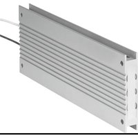
Brand : Festo
Model : CACR-KL2-40-W2000
Category : Electric resistance