ATCO-513NB-1 - Oven Atosa - Free user manual and instructions
Find the device manual for free ATCO-513NB-1 Atosa in PDF.

| Product Type | Oven |
| Brand | Atosa |
| Model | ATCO-513NB-1 |
| Dimensions (W x D x H) | 36 x 36 x 58 inches |
| Weight | 200 lbs |
| Power Type | Gas (Natural or Propane) |
| Number of Shelves | 5 |
| Temperature Range | 150°F - 500°F |
| Control Type | Manual thermostatic knobs |
| Construction Material | Stainless steel interior and exterior |
| Door Type | Double-pane glass |
| Lighting | Interior oven light |
| Thermostat | Adjustable with safety shut-off |
| Ignition | Piezo electric or standing pilot |
| Venting | Exhaust flue at top |
| Cleaning | Manual cleaning required |
| Safety Features | Flame failure thermocouple, cool-touch handle |
| Warranty | 1 year parts and labor |
| Repairability | Spare parts available through authorized dealers |
| Energy Efficiency | Standard commercial grade |
Frequently Asked Questions - ATCO-513NB-1 Atosa
User questions about ATCO-513NB-1 Atosa
0 question about this device. Answer the ones you know or ask your own.
Ask a new question about this device
Download the instructions for your Oven in PDF format for free! Find your manual ATCO-513NB-1 - Atosa and take your electronic device back in hand. On this page are published all the documents necessary for the use of your device. ATCO-513NB-1 by Atosa.
USER MANUAL ATCO-513NB-1 Atosa
Gas-Fired Convection Oven Operating Instructions
Before you begin, please read these instructions carefully to use this product correctly, to make the product perform ideally, and to avoid hazards.
Dear customers and users:
Thank you for purchasing our products. In order to be able to better use this product, please read these instructions carefully before any operation, and follow the guide, to avoid any unnecessary trouble during using.
Please keep this instruction manual in a safe place for convenient reference and operation.
This instruction manual is subject to any change without further notice, and the manufacturer reserves the right of final interpretation.
The appliance is designed for commercial purposes, not for household use.
DANGER
If you smell gas:
● Shut off gas to the appliance.
- Extinguish any open flame.
- If odor continues, keep away from the appliance and immediately call your gas supplier or your fire department.
FOR YOUR SAFETY
Do not store or use gasoline or other flammable vapors or liquids in the vicinity of this or any other appliance.
WARNING: Improper installation, adjustment, alteration, service or maintenance can cause property damage, injury or death. Read the installation, operating and maintenance instructions thoroughly before installing or servicing this equipment.
Gas-Fired Convection Oven
The Installation, Operation and Maintenance Guide
Contents
- Safety Protection....3
- Brief Introduction......3
- Manufacturer's Authority and Responsibility....3
- Parameter Specifications……4
- Transport and Storage....8
- Installation and Debugging......8
- Safety Notices and Precautions....14
- Operating Instructions 15
- Cleaning and Maintenance 20
- Electrical Schematic 24
1、Safety Protection
⚠️ Please make sure that the operator is an authorized and licensed technician before you allow him/her to install and operate the products. Be sure to strictly follow this instruction guide during installation and using. The manufacturer is not responsible for any dangers or accidents caused by improper operation or maintenance.
Do not store flammable or explosive objects around the product. Keep all flammable and explosive objects at a safe distance away from the product for normal use.
⚠️ Place the product in a reasonable position. Regarding related matters of gas, customer should execute the requirements of local gas supply sector;
⚠️ If you smell a gas leak, turn off the gas valves immediately and call the gas company:
The product should not be operated by those under 18 years of age, or those with physical or mental disorders, or disabilities that lack the necessary knowledge or experience unless with appropriate instructions and sufficient safety.
2、Brief Instruction
Such product is the Gas-Fired Convection Oven manufactured by us. The product is in novel design, reasonable structure, durable and easy to operate and maintain. This product has a pulse autoignition function for more convenient operation; a double-speed heat cycling method is employed and the burner flow is controlled to make the temperature in the oven uniform; accurate control of time and temperature. It is an ideal cooking appliance in the industry of hotel, supermarket, western restaurant, fast food restaurant and food.
3、Manufacture's Authority and Responsibility
Banning of all or partial transformation to the products without the manufacturer's explicit authorization.
Manufacturers refused to undertake responsibility to third parties as the following reasons:
⚠️ Not follow this instruction guidance and warning in in using and testing;
⚠️ Not in accordance with the requirements of technical parameters using this product:
⚠️ Incorrectly or irrationally using the product by untrained personnel;
⚠️ Not obey the local law using this product;
⚠ Be repaired or changed by unauthorized technicians;
⚠ Use the spare parts or accessories provided by non-manufacturers;
⚠️ Accidents caused by force majeure;
⚠️ Not strictly comply with related guide of this instruction by any reason.
4、Parameter Specifications
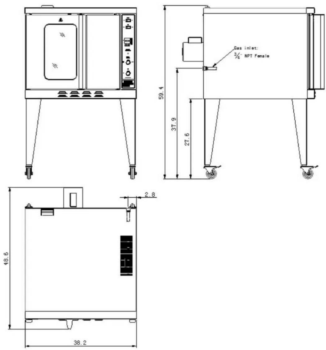
4.1、ATCO-513A
4.2、ATCO-513A-D
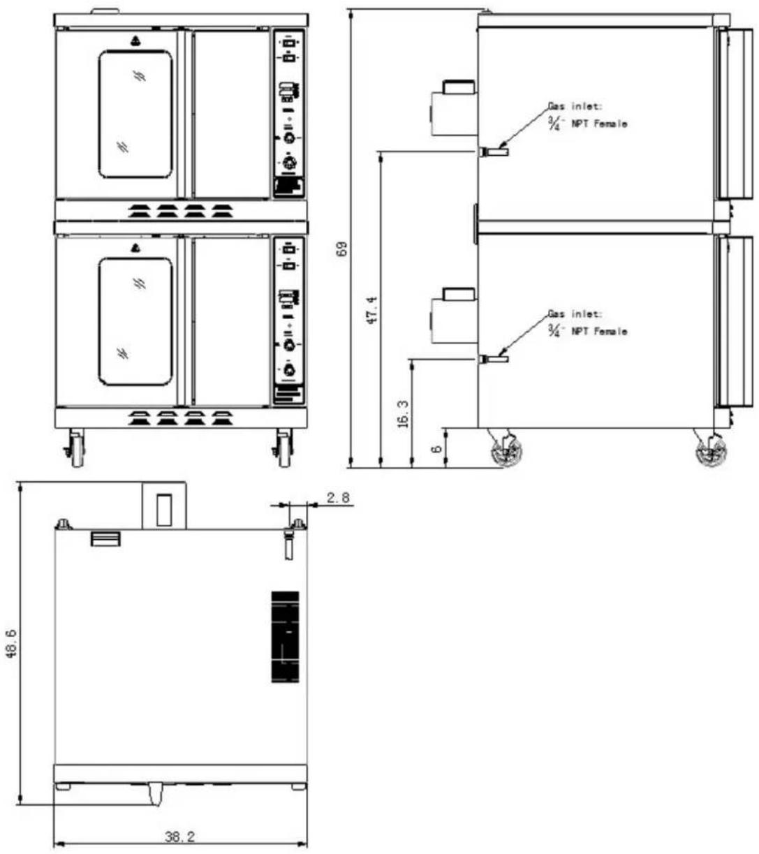
4.3、ATCO-513B
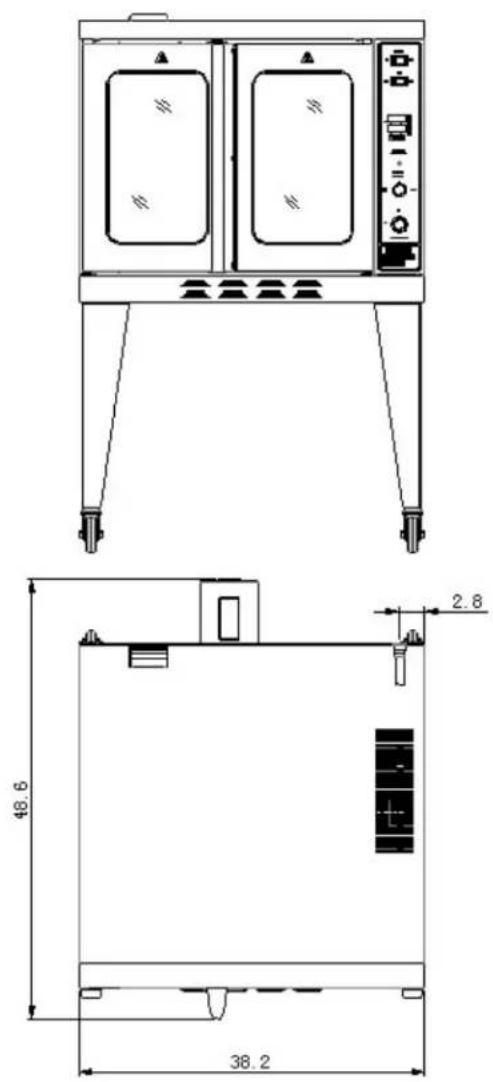
4.4、ATCO-513B-D
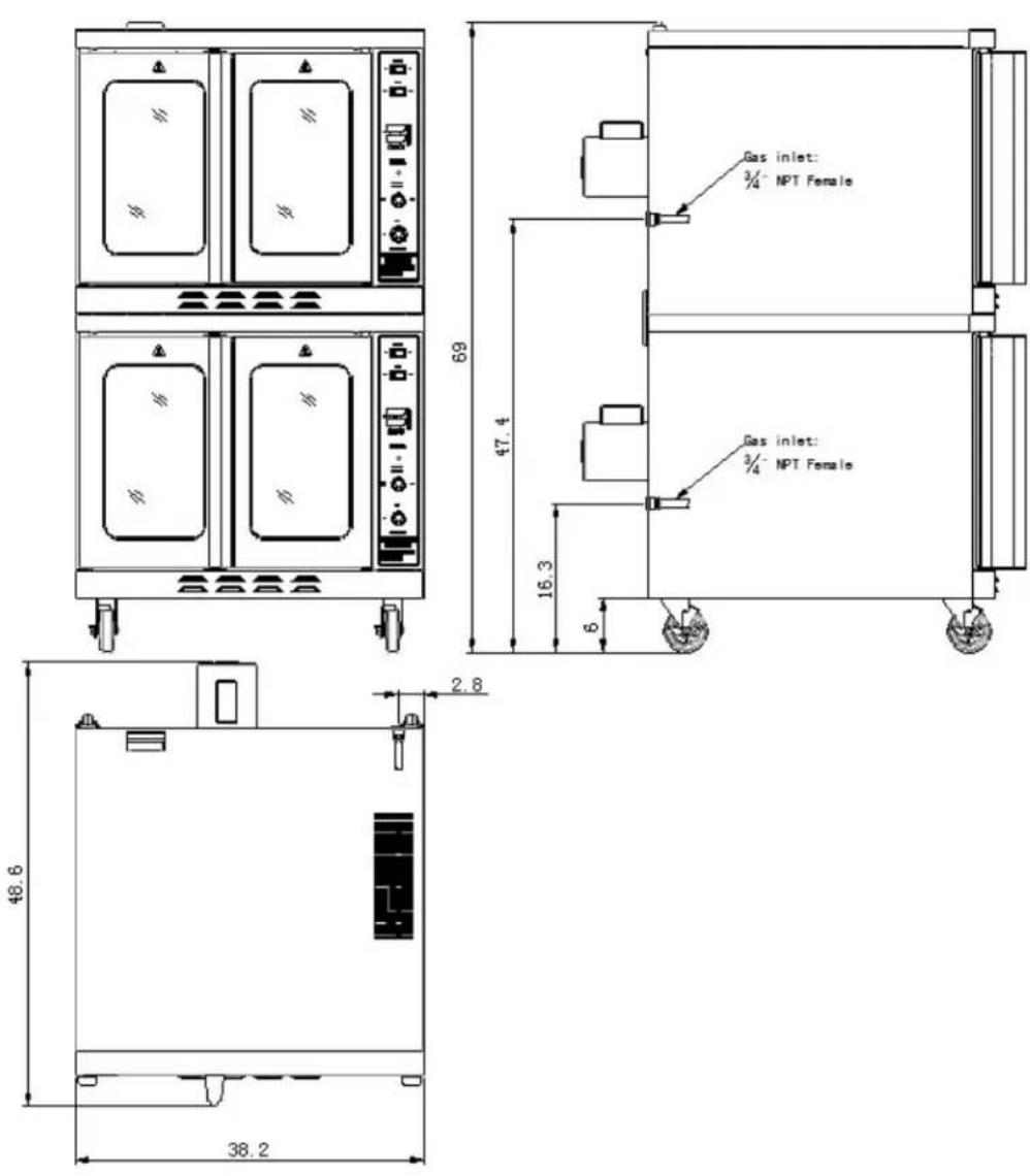
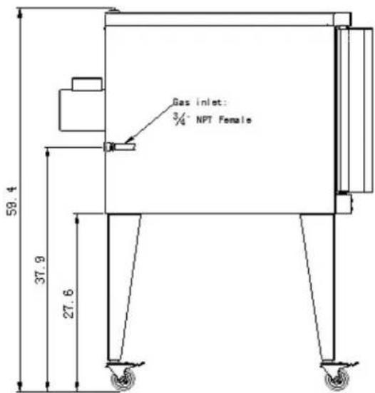
Information of Gas Supply and Electric:
The internal thread of product's intake-tube is 3/4" NPT.
DO NOT EXCEED GAS PRESSURES GREATER THAN THE FOLLOWING: (Table 1)
| GAS PRESSURE NATURAL GAS PROPANE GAS | |
| AT INLET 13.84 in.W.C./3.45kPa | 13.84 in.W.C./3.45kPa |
| AT MANIFOLD 3.5 in.W.C./0.87kPa | 10 in.W.C./2.49kPa |
| PER BURNER 23,000 BTU/HR 23,000 BTU/HR | |
| PER OVEN 46,000 BTU/HR 46,000 BTU/HR | |
| INJECTOR 43#(φ2.26mm) 54#(φ1.40mm) | |
| VOLTS 115 | |
| AMPS 9.0 | |
| PH. 1 | |
| IIZ. | 60 |
5. Transport and Storage
In the process of transportation, handle carefully and keep upright to prevent damage of the product packing. Wrapped equipment should not be in open air for a long time, and shall be placed in a well-ventilated and non-corrosive gases warehouse. When equipment needs temporary storage, rainproof measures should be taken.
6. Installation and Debugging
Any erroneous installation, adjustment, refit, overhaul or maintenance may cause property damage or personal injury. The work shall be performed by authorized and licensed technicians, otherwise the manufacturer has the right not to provide warranty service;
Only be installed in accordance with the local code. If no similar standard, you should conform to the National Fuel Gas Code, ANSI Z223.1/NFPA 54, the National Gas Installation Code, CSA-B149.1, or the L.P. Gas Installation Code, CSA-B149.2 as applicable;
The installation of electrical wiring from the electricmeter, main control box or service outlet to the electrical appliance. Qualified installation personnel must be familiar with all precautions required and have complied with all requirements of state and local authorities having jurisdiction. See: National Electrical Code, ANSI/NFPA70.
The appliance individual shutoff valve must be disconnected from the gas supply piping system during any pressure testing of that system at test pressures in excess of 1/2psi (3.45kPa).
For an oven equipped with casters, the installation shall be made with a connector that complies with the Standard for Connectors for Movable Gas Appliances, ANSI Z21.69/CSA 6.16 and a quick-disconnect device that complies with the Standard for Quick-Disconnect Devices for Use with Gas Fuel, ANSI Z21.4/CSA6.9. When installing the oven with casters and quick-disconnect hose, adequate means must be provided to limit the movement of the oven without depending on the connector and the quick disconnect device or its associated piping to limit the oven movement. Restraining means may be attached to the vertical portion of the base frame in the rear of the oven.
Unpacking and Installation
⚠️ Please dispose of all packaging materials and residues after unpacking;
⚠️ Check the equipment. If it is damaged, please keep wrappers and receipts which must be signed by the carrier representative (Driver), and contact the carriers to pursue a claim within 15 days after receiving;
⚠ Be sure to install supporting legs before using, and do not tear up any label or logo before normal using;
⚠️ Please read these instructions carefully before installation and operation. Please contact your local agent if you have any questions;
Such stove shall be installed on the horizontal, solid, anti-skidding and incombustible floor, and at the water-proof working area with sufficient light and far away from the children and customers;
The installation position is a well-ventilated place in accordance with the local regulations;
The charbroiled must be installed under the matched cooking fume exhauster according to the local regulations;
⚠️ Important: Installation and ventilation laws, and codes are very different, you should state and comply with all codes of the National Fire Protection Association Inc when it comes to requirements for installation of equipment;
⚠ Hoist the product using a forklift to some height, fix the supporting leg to 3 corresponding holes of the baseplate using a 8 flat gasket, 8 spring gasket and M8×25 screws and screw such screws with a spanner. If a castor is installed, its screws shall be screwed into the corresponding hole of the baseplate, as shown in Figure below.
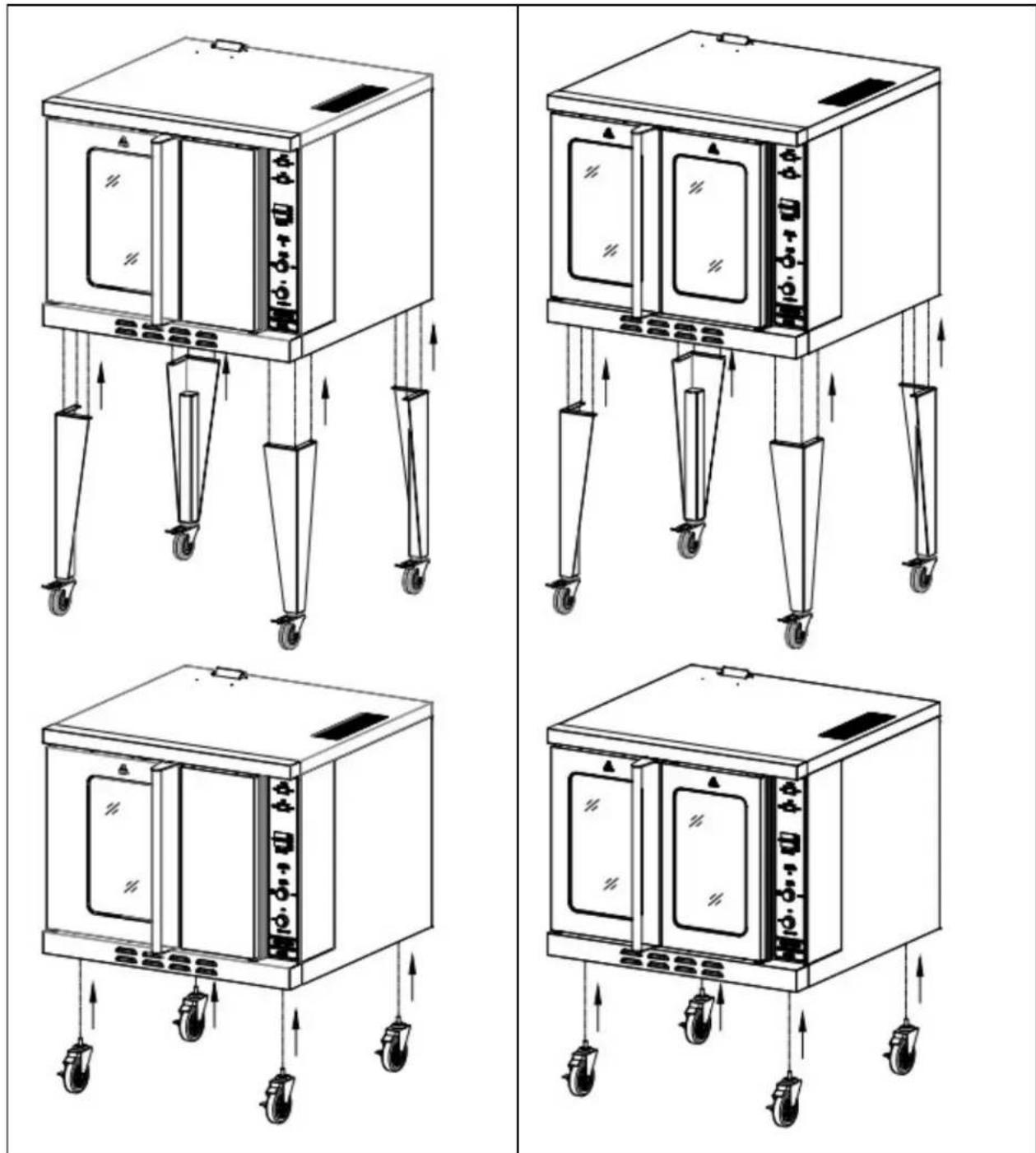
natural_image
Four technical line drawings of a laboratory oven with wheels and control panels, showing mechanical assembly (no text or symbols)⚠️ Mounting Stacking Bracket
-
Install 4 pcs 5" castors or short legs to the baseplate of the bottom oven, as described in the previous section.
-
Put the oven on the upper layer to that on the lower layer and align the edges of all ovens.
-
Dismantle two existing screws on the rear lower part of the oven on the upper layer and dismantle one existing screw on the rear upper part of the oven on the lower layer.
-
Install the stacking bracket using the existing screws and those in the packaging bag.
-
Repeat the steps and install the second stacking bracket on the other side.
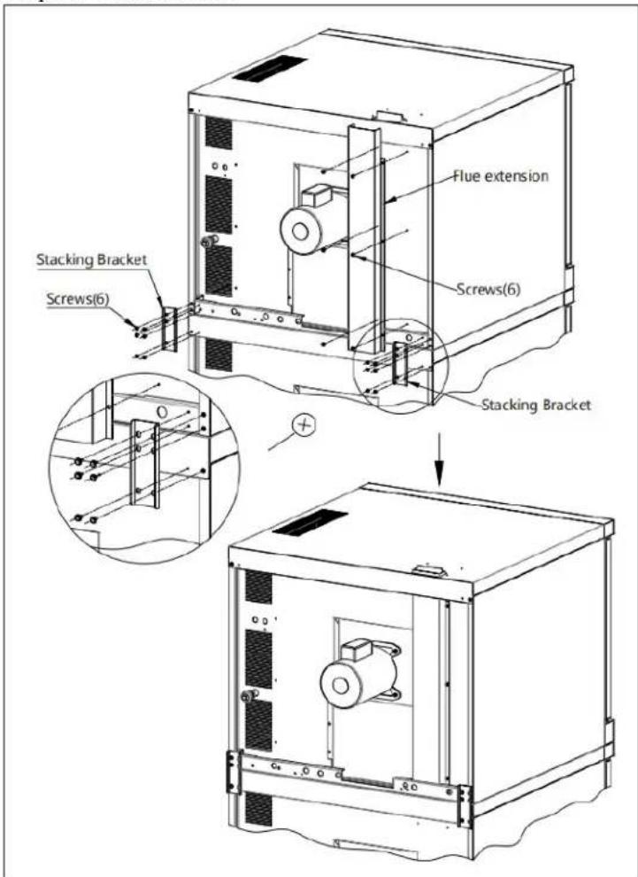
⚠️ Mounting Flue Extension to Top Oven
-
Take out the flue out of the packaging box and insert its upper part from bottom to top into the opening at the rear upper part of the oven on the upper layer.
-
Align the lower part of the flue with the opening of the baseplate at the rear lower part of the oven on the upper layer.
-
Align the hole on the flue with that on the rear plate of the oven on the upper layer and fix it on the rear plate with 6 screws.
The area around the oven must be kept clear of combustible materials.
A minimum clearance must be maintained between the oven and any combustible or non-combustible surface;
MINIMUM CLEARANCES
| Combustible Non-Combustible | ||
| RIGHT SIDE 1" 1" | ||
| LEFT SIDE 1" 1" | ||
| REAR 6 6 | ||
| FLOOR 6" 6" |
Do not put anything around the equipment, and on the counter top and bottom, in order to avoid influencing combustion and air circulation;
This oven has been tested and certified for use on gas systems that do not exceed 1/2 psi (3.45kPa) or pressure. If the piping system is tested at a pressure higher than 1/2 psi (3.45kPa), this oven should be isolated from the supply by disconnecting it. If the piping system is tested at a pressure lower than or equal to 1/2 psi (3.45kPa), this oven should be isolated from the supply by shutting off the manual shut off valve located on the front panel.
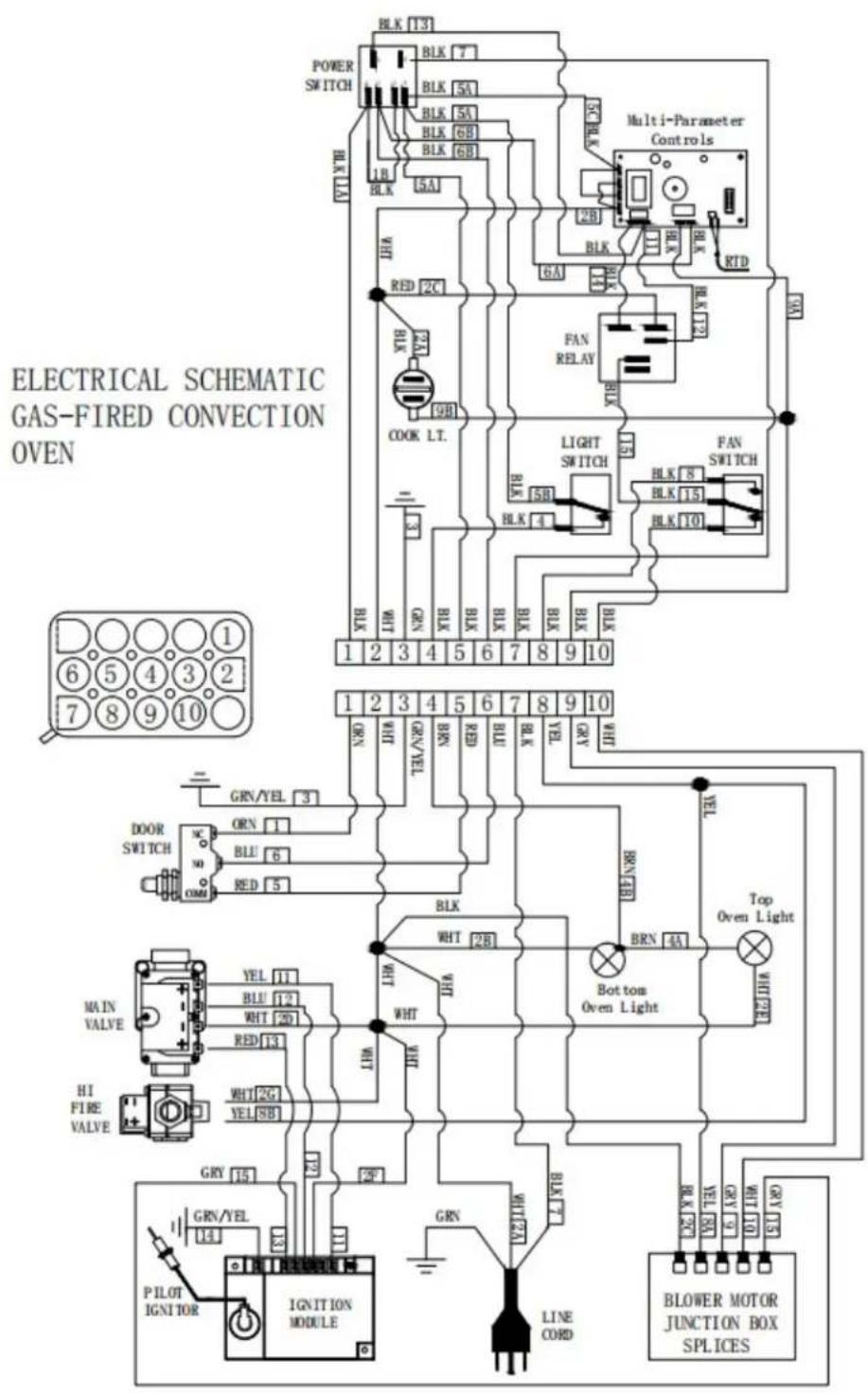
ELECTRICAL CONNECTIONS
Your oven is supplied for connection to a 115 volt, single phase grounded circuit. The electric motor, oven lights, indicator lights and control circuits are connected through a seven-foot electric supply cord found at the rear of the oven.
Before making any connections to these units, check the rating plate to assure that the voltage and phase of the oven is compatible with the electrical supply. When installing, all ovens must be electrically grounded in accordance with local codes, or in the absence of local codes, with the National Electrical Code, ANSI/NFPA70 (in Canada-CSA Std.C22.2). Wiring diagrams are located in the control compartment area of the oven. Standard wiring schematics are also provided with this manual.
WARNING: This appliance is equipped with a three-prong (grounding) plug for your protection against shock hazard and should be plugged directly into a properly grounder three-prong receptacle. DO NOT cut or otherwise remove the grounding prong from this plug.
VENTILATION
⚠️ Proper ventilation is very important for the proper function of your oven. A good ventilation system will allow the oven to function properly as well as remove unwanted vapors and products of combustion. Not venting the ovens properly can result in unsatisfactory baking results as well as the possibility of damaging your oven. To keep your warranty in force, a proper ventilation system must be employed, either direct vented or under a canopy;
⚠ Warning! Use soap water or testing instrument to test whether piping joint leaks or not before using, and forbid using an open flame to test!
After installing completely, you should check gas supply pressure. Use a pressure gauge which is equipped with liquid (such as U-type pressure gauge, the minimum value is 0.1mbar) or a digital pressure gauge to test. Steps are as following:
●After opening the door, loosen the four screws that hold the lower panel, pull the panel out, and the pressure test point is on the right.
- Remove needle type pressure joint screw arbor (Fig. 1), then slip rubber tube of pressure gauge over needle type pressure joint;
●Start the equipment in accordance with the instructions, measuring gas supply pressure (dynamic pressure) in the work state;
- Access to the equipment if measured data within the limits of Table 1, otherwise, you will need to adjust gas pressure regulating valve or contact gas supplier to bargain;
●Unplug pressure gauge after you accomplish pressure testing, then install needle type pressure joint screw arbor.
Important: must screw joint screw arbor, to prevent gas escape!
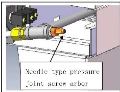
Figure 1
It's very important to debug the new stove. Through the comprehensive system test of equipment, we can ensure function and safety performance of products. Discovering any potential problems before use (such as equipment's placement, ventilation, operation, etc), can avoid costly losses.
7. Safety Notices and Precautions
⚠ Warning! For your safety, do not place petrol and other flammables nearby. Please keep clean and free of flammables surroundings. (Read ANSI Z83.14B, 1991 for reference)
⚠ Warning! Any erroneous installation, adjustment and refit may cause property damage or personal injury and maintenance failure. Read the instructions carefully before installation and using.
⚠ Warning! Operation instruction must be placed in a conspicuous location. When customers smell gas in the process of using, should take safety precautions immediately. Immediately turn off the main gas valve, extinguish all heat and flames, and call 911. Safety information can be obtained from your local gas suppliers.
When using this equipment, safety precautions should always be followed, including the following:
External surface will still be scalding after being used. You must take care when touching these positions;
⚠️ Turn off the equipment as repairing, maintaining and cleaning;
If the equipment has any problems of equipment damage, gas piping leaks, igniter or valves damage, or lose product accessories, do not operate, and call for the service immediately;
The use of attachments not recommended or sold by the manufacturer may cause fire, personal injury or even death;
⚠️ Do not use out of doors;
Such appliance is used to bake the food and shall not be used for other purposes;
The equipment does not contain any user-serviceable parts. Dealers or technicians will repair it. Do not take apart any spare parts without authorization;
Never change any other parts without authorization to this equipment, otherwise, may cause hazards, and the manufacturer has the right not to
provide warranty service;
⚠️ Steel cutting producers used to manufacture with sharp edges. The manufacturer has dealt with these sharp edges during production, however, we insist the operator take care when in contact with this piece of equipment;
⚠️ Always keep hands, hair and clothing away from heating source.
⚠ Wait the unit cools down before cleaning. Because the unit is too hot to handle after using.
8. Operating Instructions
Do not use fan or air-conditioning blowing at the flame, in order to avoid extinguishing flame and cause safety accidents;
⚠️ Install the matched cooking fume exhauster according to the local regulations of char broiler;
⚠ Make sure to keep the natural air circulation in the kitchen.
The information in this section is intended for the use of qualified operating personnel. Qualified Operating Personnel are those individuals who have carefully read the information contained in this manual, are familiar with the function of the oven and/or have had experience with operating the equipment described. We recommend following these instructions to insure optimum performance, long life and trouble-free service from your oven.
WARNING: The gas-fired Convection Ovens rely on electricity for powering the ignition system and the fan. Do not attempt to operate during a power failure.
CONTROLLER PANEL
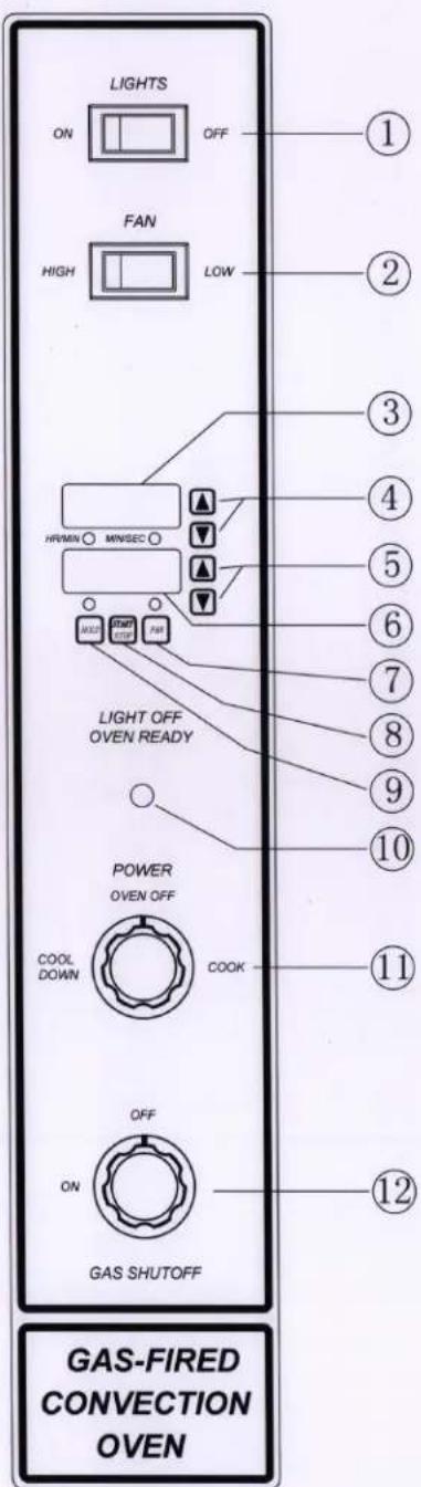
- Light Switch: Turns oven lights on/off.
- Fan Speed Switch: (Optional) - Sets fan speed to high or low.
- Time Digital display: Displays time remaining in the chosen cycle.
- Time Adjustment buttons: Sets/Adjusts count down timer for cook cycle.
- Temperature Adjustment Buttons: Sets / Adjusts cooking temperature.
- Temperature Digital Display: Displays the temperature inside the oven.
- Pulse Fan Button: Enable/Disables the Pulse Fan function.
- Start/Stop Button: tarts/Stops the cooking cycle.
- Hold Button: Enable / Disables the Hold function.
- Indicator Light: When lit indicates burners or elements are operating. When the light goes out, he oven has reached the desired temperature.
- Power Switch: Controls power to Cook or Cool Down functions.
- Gas OFF/ON Button: huts the gas OFF or turns the gas ON.
Programming and Operating Instructions
Models with the controller enable the oven to cook food at a specified temperature for a specified time period, than enter an optional hold mode,. The hold mode holds food at a specified temperature for a specified period of time.
When the power switch is in the ON position the oven will be in one of two modes:
-
Cook Mode: In this mode the oven operates at a specified temperature and the fan runs continuously, unless the cycle option is selected. In cycle mode the fan runs for 30 seconds and is off for 30 seconds. This cycle continues during the specified cook time.
-
Hold Mode : In this mode the oven operates at a specified hold temperature, however the fan only runs when the burners are on . If the fan mode switch is in the COOL position the fan will run continuously in the Hold mode.
To Program Cook Mode do the following:
-
Turn the power switch ON. The power switch is located in the middle of the Control Panel.
-
Set the desired cook temperature (150°F-550°F). Use the arrow keys located next to the temperature display. Up raises the temperature, down lowers the temperature.
-
Set the Fan Mode Switch to the Cook position. In the Cook position the fan will not run when the doors are open. If the Fan Mode Switch is set in the COOL position the fan will run when the doors are open.
-
If fan cycling is desired press the FAN button. In this mode the fan runs for 30 seconds and is off for 30 seconds. The fan indicator light will blink when the fan is in cycle mode. It stays on steady when the fan is in continuous run mode.
-
Select the correct fan speed for the item being cooked. The Fan Speed switch has two speeds, HI or LOW.
-
Set the desired cook time by using the up and down arrows next to the cook time display. Up increases time, down decreases time.
-
If the Hold Mode is going to be used for the product being cooked, press the HOLD button. The temperature display now displays the Hold temperature. Use the up and down arrows to set the desired holding temperature.
-
Wait until the temperature display stops flashing, when it stops flashing the oven has reached the set temperature. The oven also beeps once to alert the user that it is ready.
-
Place the product to be cooked into the oven and press the START/STOP button. The time display begins counting down the remaining cook time. If the oven doors are opened during the cook cycle, the timer will pause, the fan will shut off and the burners will shut off. The cook cycle will resume when the doors are closed.
For ovens equipped with an interior light, the light may be turned on by pressing and holding the LIGHTS button at the top of the Control Panel.
The cook time, oven temperature and fan cycle mode can be changed during the cook cycle as needed.
To cancel a cook cycle press, the START/STOP button.
- If the HOLD mode is NOT enabled the oven begins beeping and the display will flash "00" indicating the cook cycle is complete. Press the START/STOP button to silence the alarm and immediately remove the product from the oven. If the oven doors are shut the oven will maintain the set cook temperature even though the timer has run out. To cool down the product, open the doors, with the Fan Mode to COOL and change the FAN SPEED to HI.
If the HOLD mode is enabled the oven will beep three times when the cool time has completed. The timer will begin an upward count, indicating how long the product has been holding The temperature display now displays the holding temperature. The oven will remain in HOLD mode until the START/STOP button is pressed. Pressing the START/STOP button returns the oven to the COOK mode.
- When cooking is completed press the Power ON/OFF button to turn the oven off.
These guidelines are to assist you in obtaining the best performance from your oven:
- Always pre-heat your oven before cooking by placing the temperature setting at the desired temperature. The oven is pre-heated when the Indicator Light
goes out.
- Always use a lower temperature setting than that recommended for a standard conventional oven or range oven. The general rule of thumb is to subtract 50-100°F from the standard oven recipe. Some experimentation on your part may be necessary to achieve the optimum results with your food products.
Cooking at higher temperatures will not reduce your cooking time! It will produce unsatisfactory baking and roasting results.
-
You should begin checking the doneness of your food product in about half the time recommended for the same recipe cooked in a standard oven. Keep in mind that your times may vary depending on the amount of product being cooked in your oven. The best results are always achieved when a systematic record of times and temperatures is kept for reference.
-
The oven will hold up to thirteen 18" x 26"(457mm x 660mm) sheet pans .Your product and pan height will determine how many racks can be loaded.
Do not place an empty sheet pan or aluminum foil on the bottom of the oven. This will disrupt the airflow and cause uneven cooking results.
- To minimize the shrinkage of roasted meats, place the meat directly on the racks and place a sheet pan one half full of water in the bottom rack position. The water will keep the oven compartment more humid and the meat juices will evaporate less.
- Maintain equal loads when cooking more than one pan of product at a time. You may wish to weigh the product to assure that the pan loads are equal. Smaller loads in one pan will cook at a different rate than larger ones in another.
- You may wish to experiment with leaving the oven OFF after pre-heating the oven and loading when baking light products such as light cake batter or custard so the product will have time to set. Normally, 7-10 minutes with the oven OFF, then finishing with the oven ON, will keep the product from rippling or being pushed by the fan.
- When starting off with frozen product, you may wish to pre-heat your oven up to 100^ F above the temperature you are going to cook. Load the product and reset the temperature for the normal time.
- For longer bulb life, do not leave the oven lights on when not viewing the product.
9. CLEANING AND MAINTENANCE
Do not use any abrasive or flammable detergent to wipe;
Do not hose down, immerse or pressure wash any part of the cooker;
Do not use abrasive cleaning matters to wash, even not use corrosive detergent!
The stainless steel on your oven can be kept clean with a good stainless steel cleaner, many of which are on the market. The painted surfaces should be wiped clean regularly with a MILD detergent.
Moisten a cloth and wipe down the oven while it is COLD. Wiping down an oven while it is hot will cause streaking and otherwise unsatisfactory results. Once the oven is clean it can be wiped down with light oil
Porcelain oven interiors should be cleaned regularly using a degreasing agent. For heavier deposits a commercial oven cleaner such as Dow Oven Cleaner, Easy-Off can be used. Care must be taken to prevent these alkaline-type cleaners from coming in contact with any aluminized steel surfaces in the oven, including the blower wheel.
The blower wheel, racks and rack supports can be removed and soaked in a solution of ammonia and water.
Warning: Disconnect the power supply to the appliance before removing blower wheel.
Make certain that all parts are thoroughly rinsed before returning to use.
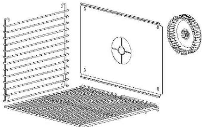
natural_image
Technical line drawing of a coiled heating element with a fan, showing internal structure and mounting base (no text or symbols)⚠ Warning: Wait for the equipment to cool down after the unit has been turned off before you clean!
Comprehensively check the equipment at least once every year by authorized and licensed technicians;
The product is made of 90% metals, and can not be discarded everywhere. Deal with it in accordance with the local codes.
⚠ Instructions to clean appliance regularly with recommended cleaning agents, if necessary.
Warning: If any fault occurs, please stop using, and contact technicians to check and repair. Safety first, turn off the power and gas supply before maintenance.
WARNING: Units provided with casters have a restraint to limit the movement of the oven. If this restraint is disconnected during servicing it must be reconnected after the appliance has been returned to its original installed position.
These maintenance instructions are for the use of qualified service personnel only. Service by other than qualified personnel may result in damage to the oven and/or injury to the operator.
Qualified service personnel are those individuals, firms, companies or corporations which either in person or through an agent are engaged in and responsible for repair or servicing of commercial food preparation equipment, who are experienced in such work, familiar with all precautions required, and have complied with all requirements of state and local authorities having jurisdiction.
ADJUSTMENTS
Quite often malfunctions, which are attributed to defects, may be repaired by adjusting certain parts rather than replacing them.
DOOR ADJUSTMENT
The gas-fired convection oven have doors that are inter-connected so they operate simultaneously by means of a chain and turnbuckle assembly. The doors are properly adjusted and inspected before the oven leaves the factory. However, from time to time it may become necessary to readjust the doors after usage. If you find it necessary to adjust the doors for proper operation, the chain and turnbuckle assembly is located behind the panel that is over the doors. It is best to adjust turnbuckles while the door is in an unlatched position.
- Loosen the jam nut on both turnbuckles.
- Make adjustments simultaneously to both turnbuckles.
- Loosening or tightening the assembly will not allow the doors to work properly. Ideally, you should loosen one turnbuckle and tighten the other.
Some
experimentation will indicate which direction you will want to make your adjustments. - Once the doors are operating properly, retighten the jam nuts so the unit stay in adjustment. Test the door to make certain it is in adjustment.
- Replace cover.
DOOR SWITCH ADJUSTMENT
You may also wish to adjust the door switch. The door switch is located behind the combustion compartment cover, on the right side. The door switch is activated by a cam, which is mounted to the door's hinge pin with a setscrew.
- Open the doors fully.
- Remove the lower cover by loosening the four screws located inside the door opening.
- Position the doors so they are nearly closed but not latched.
-
To adjust the cam loosen the setscrew and rotate the cam until you hear the switch click.
-
Tighten the setscrew in the cam. Test the door to make certain the switch will make contact with the doors closed.
-
Torque setscrew to 60 in-lbs.
- Replace the combustion cover.
WARNING : The door turnbuckles and door switch are located in a heated in a heated zone. Care should be taken to avoid burns.
VENTILATION SYSTEM
It is important that the ventilation system be inspected and/or maintained by Qualified Personnel at least once each year.
This inspection/maintenance should consist of, but not be limited to:
- Inspection for blockages or build up which might interfere with the venting the venting of the oven.
- Repair of such blockages.
- Proper installation of the draft hood or flue guard.
- Inspection of the venting canopy, its drive motors and belts, etc.
- Proper preventive maintenance can reduce your chances of costly repairs.
10、ELECTRICAL SCHEMATIC

Intertek

Intertek
4003935
Conforms to ANSI STD Z83.11-2016
Certified to CSA STD 1.8-2016
Conforms to NSF/ANSI STD.4
- Gas-Fired Convection Oven Operating Instructions
- DANGER
- FOR YOUR SAFETY
- Gas-Fired Convection Oven
- Contents
- 1、Safety Protection
- 2、Brief Instruction
- 3、Manufacture's Authority and Responsibility
- 4、Parameter Specifications
- 4.1、ATCO-513A
- 4.4、ATCO-513B-D
- Information of Gas Supply and Electric:
- Transport and Storage
- Installation and Debugging
- Unpacking and Installation
- ⚠️ Mounting Stacking Bracket
- ⚠️ Mounting Flue Extension to Top Oven
- ELECTRICAL CONNECTIONS
- VENTILATION
- Safety Notices and Precautions
- Operating Instructions
- CONTROLLER PANEL
- Programming and Operating Instructions
- To Program Cook Mode do the following:
- CLEANING AND MAINTENANCE
- ADJUSTMENTS
- DOOR ADJUSTMENT
- DOOR SWITCH ADJUSTMENT
- VENTILATION SYSTEM
- 10、ELECTRICAL SCHEMATIC
Brand : Atosa
Model : ATCO-513NB-1
Category : Oven