CM5000 - Security Camera AVer - Free user manual and instructions
Find the device manual for free CM5000 AVer in PDF.


| Product Type | Security Camera (IP) |
| Model | CM5000 |
| Brand | AVer |
| Maximum Resolution | 5 MP (2592x1944) typical |
| Video Compression | H.264 |
| Frame Rate | Up to 30 fps at 5 MP |
| Lens | Motorized varifocal, auto focus |
| Night Vision | IR LEDs with IR-cut filter, up to 30m |
| Power Supply | PoE (IEEE 802.3af) or 12V DC |
| Dimensions | Approx. 120 x 80 x 70 mm |
| Weight | Approx. 500 g |
| Weatherproof Rating | IP67 (outdoor use) |
| Operating Temperature | -20°C to 50°C |
| Storage Temperature | -20°C to 60°C |
| Audio Support | Two-way audio (built-in mic and speaker) |
| Alarm I/O | 1 input, 1 output (relay) |
| Smart Features | Motion detection, tampering, cross line, missing object, suspicious object |
| Storage | MicroSD card up to 128 GB (optional) |
| Network Protocols | IPv4, TCP/IP, UDP, HTTP, DHCP, DNS, DDNS, NTP, SMTP, FTP |
| Mobile App Support | AVer Surveillance Go for iOS/Android |
| Maintenance | Clean lens with soft dry cloth; avoid solvents; keep firmware updated via web interface |
| Safety | Do not disassemble; use only supplied adapter; keep away from water and extreme heat |
| Spare Parts / Repair | Contact AVer support or authorized service center; no user-serviceable parts inside |
Frequently Asked Questions - CM5000 AVer
User questions about CM5000 AVer
0 question about this device. Answer the ones you know or ask your own.
Ask a new question about this device
Download the instructions for your Security Camera in PDF format for free! Find your manual CM5000 - AVer and take your electronic device back in hand. On this page are published all the documents necessary for the use of your device. CM5000 by AVer.
USER MANUAL CM5000 AVer
This device complies with Part 15 of the FCC Rules. Operation is subject to the following two conditions: (1) this device may not cause harmful interference, and (2) this device must accept any interference received, including interference that may
cause undesired operation.
Federal Communications Commission Statement
NOTE- This equipment has been tested and found to comply with the limits for a Class A digital device, pursuant to Part 15 of the FCC Rules. These limits are designed to provide reasonable protection against harmful interference in a residential installation. This equipment generates uses and can radiate radio frequency energy and, if not installed and used in accordance with the instructions, may cause harmful interference to radio communications. However, there is no guarantee that interference will not occur in a particular installation. If this equipment does cause harmful interference to radio or television reception, which can be determined by tuning the equipment off and on, the user is encouraged to try to correct the interference by one or more of the following measures:
■ Reorient or relocate the receiving antenna.
■ Increase the separation between the equipment and receiver.
■ Connect the equipment into an outlet on a circuit different from that to which the receiver is connected.
■ Consult the dealer or an experienced radio/television technician for help.
Class A ITE
Class A ITE is a category of all other ITE which satisfies the class A ITE limits but not the class B ITE limits. Such equipment should not be restricted in its sale but the following warning shall be included in the instructions for use:
Warning -This is a class A product. In a domestic environment this product may cause radio interference in which case the user may be required to take adequate measures.
European Community Compliance Statement (Class A)

This product is herewith confirmed to comply with the requirements set out in the Council Directives on the Approximation of the laws of the Member States relating to Electromagnetic Compatibility Directive 2004/108/EC.
Warning - This is a Class A product. In a domestic environment this product may cause radio interference in which case the user may be required to take adequate measures to correct this interference.
DISCLAIMER
No warranty or representation, either expressed or implied, is made with respect to the contents of this documentation, its quality, performance, merchantability, or fitness for a particular purpose. Information presented in this documentation has been carefully checked for reliability; however, no responsibility is assumed for inaccuracies. The information contained in this documentation is subject to change without notice.
In no event will AVer Information Inc. be liable for direct, indirect, special, incidental, or consequential damages arising out of the use or inability to use this product or documentation, even if advised of the possibility of such damages.
TRADEMARKS
“AVer” is a trademark owned by AVer Information Inc. Other trademarks used herein for description purpose only belong to each of their companies.
COPYRIGHT
© 2014 AVer Information Inc. All rights reserved.
All rights of this object belong to AVer Information Inc. Reproduced or transmitted in any form or by any means without the prior written permission of AVer Information Inc. is prohibited. All information or specifications are subject to change without prior notice.
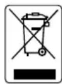
The mark of Crossed-out wheeled bin indicates that this product must not be disposed of with your other household waste. Instead, you need to dispose of the waste equipment by handing it over to a designated collection point for the recycling of waste electrical and electronic equipment. For more information about where to drop off your waste equipment for recycling, please contact your household waste disposal service or the shop where you purchased the product.
Battery Safety Information
- Store the batteries in a cool dry place.
- Do not dispose of used batteries in domestic waste. Dispose of batteries at special collection points or return to point of sale if applies.
- Remove the batteries during long periods of non-use. Always remove exhausted batteries from the remote control. Battery leakage and corrosion can damage this remote control, dispose of batteries safely.
- Do not mix old and new batteries.
- Do not mix different types of batteries: alkaline, standard (carbon-zinc) or rechargeable (nickel-cadmium).
- Do not dispose of batteries in a fire. The batteries may explode or leak.
- Never short circuit the battery terminals.
Contents
CHAPTER 1 HARDWARE INTRODUCTION....1
1.1 Package Contents....1
P5036-R 1
P5036-16-R....1
1.2 Front Panel 2
1.3 Back Panel....3
P5036-R 3
P5036-16-R 4
1.4 Hard Disk Installation....5
1.4.1 Install Hard Disk inside HDD Bay 5
1.4.1 Install Internal Hard Disk 7
1.5 Pin Definition of Sensor/Relay/RS485 Port 9
CHAPTER 2 MAIN SYSTEM CONFIGURATION ...... 11
2.1 Getting Started.... 11
2.1.1 Familiarizing Icons on Dialog Box 12
2.2 Familiarizing Functions in Preview Mode....13
2.3 Familiarizing Functions in Playback Mode 16
2.4 Compact Mode....21
2.4.1 Familiarizing Function in Preview Compact Mode....22
2.4.2 Familiarizing Function in Playback Compact Mode 24
2.5 System Setup 28
2.5.1 General System Setting....29
2.5.2 System Advanced Setting....30
2.5.2.1 Daylight Saving Time Setting....31
2.5.2.2 Customizing System Login Setting 32
2.5.3.3 Customizing System Miscellaneous Setting.... 33
2.5.4 Update/Export/Import 34
2.5.4.1 Importing NVR/DVR System Configuration.... 35
2.5.4.2 Exporting NVR/DVR System Configuration 36
2.5.4.3 Upgrading NVR/DVR Firmware 37
2.5.4.4 Upgrading IP Camera Module Patch 38
2.5.5 Setup Dual Monitor 39
2.5.6 Reset to Factory Default....40
2.6 Network Setting....41
2.6.1 Setup NVR/DVR Server Name 43
2.6.2 Network Advanced Setting 44
2.6.2.1 Setup Transmitting Camera 45
2.6.2.2 Setup UPnP 45
2.6.2.3 Setup Bandwidth Limit 45
2.6.2.4 Setup Network Port 45
2.7 Storage Setting 46
2.7.1 Formatting Hard Disk....47
2.7.2 Creating RAID Drive 48
2.7.3 Setup Storage Path for Recording Data 52
2.7.4 Setup Hard Disk and Event Log Recycle Time....54
2.7.5 iSCSI Setting 55
2.8 Camera Management 57
2.8.1 Connect the Analog Camera 58
2.8.2 Connect the IP Camera....59
2.8.2.1 Use Active IP Function 62
2.8.3 Camera Detail Configuration 64
Info 64
Basic....65
Preference 66
Exposure 68
Stream 69
ROI....70
Smart Stream....71
Privacy Mask 72
Motion Detection 73
IVA 74
Cross Detection 75
Tampering....76
Missing Object....77
Suspicious Object....78
Sensor 79
Relay 80
MFZ....81
PTZ Function 83
2.8.3 Familiarizing Functions on PTZ Control Panel 85
2.9 Record Management 87
2.10 Alarm Schedule Setting 90
2.11 Backup Setting....91
2.12 Alarm Setting 93
2.12.1 Setup Alarm Condition 93
2.12.2 Setting Alarm Action....99
2.13 User Account Setting 107
2.13.1 Creating an User Account.... 107
2.12.1 Deleting an User Account.... 110
2.14 I/O Setting....111
2.14.1 Sensor Setting....111
2.14.2 Relay Setting 112
2.15 Emap Setting 113
2.15.1 Setting Emap.... 113
2.16 iPOS Setting 115
2.17 Log Viewer.... 118
2.17.1 Using the Event Log Viewer 118
2.17.2 Using the Alarm Log Viewer 121
Viewing Alarm Event 121
Searching Alarm Event Logs 123
2.17.3 Using POS Log Viewer....125
2.18 NVR/DVR System Tools 127
2.18.1 Hard Disk Calculator....127
2.18.2 Using On Screen Keyboard....128
CHAPTER 3 MONITORING THE NVR/DVR....129
3.1 Managing Camera Channels 130
3.2 Meaning of Icons and Figures....131
3.3 Enable/Disable the Camera Channel....132
3.4 Changing Screen Channel Display Mode 132
3.5 Enable/Disable the Sound of the Channel 133
3.6 Switching Multiple Screen to Single Screen Display 133
3.7 Viewing Emap....134
3.8 Snapshot the Screen 135
3.9 Full Screen Display....136
3.10 Hiding Camera List 137
3.11 Auto Display Channel in Cycle....138
3.12 Enable/Disable 2-Way Audio Function....139
CHAPTER 4 PLAYBACK RECORDED VIDEO ON NVR/DVR SYSTEM.....140
4.1 Playback on NVR/DVR System 140
4.2 Playback the Specific Date/Time Period 141
4.3 Using Event Search to Playback the Event....142
4.4 Using Visual Search to Playback the Specific Time 144
4.5 To Bookmark a Section of the Video for Playback 146
4.6 Playback Mode Management 148
4.6.1 Managing Channel Display Position....148
4.6.2 Enable/Disable Sound of the Channel....149
4.6.3 Switching Multiple Screen Display to Single Screen Display..... 150
4.6.4 Full Screen Display....151
4.6.5 Hiding Camera List....152
4.6.6 Output a Video Clip to a USB Pen Drive 153
4.6.7 Snapshot the Screen View 155
CHAPTER 5 PLAYBACK BY QPLAYER....156
5.1 Familiarizing Functions of Qplayer....157
5.1.1 To Bookmark a Section of the Video for Playback....161
CHAPTER 6 USING THE PCVIEWER....163
6.1 Familiarizing Functions of PCViewer 164
APPENDIX USB RECOVERY 165
WARRANTY NOTICE....167
Chapter 1 Hardware Introduction
1.1 Package Contents
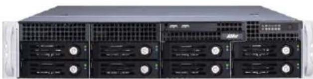
P5036-R
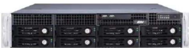 | 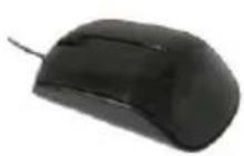 | 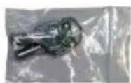 | ||||
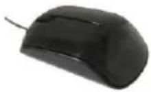
| P5036-R NVR unit | USB optical mouse | Key for HDD bay | ||||
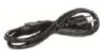 |  |  |  | |||
| *Power cable | Software CD | Manual CD | Screws | |||
* Then power cord may vary as it is country dependent.
P5036-16-R
 |  | 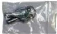 | ||||
| P5036-16-R DVR unit | USB optical mouse | Key for HDD bay | ||||
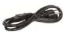 |  |  |  | 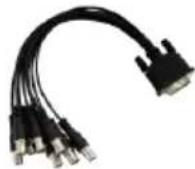 | ||
| *Power cable | Software CD | Manual CD | Screws | DVI cable x 2 | ||
* Then power cord may vary as it is country dependent.
1.2 Front Panel
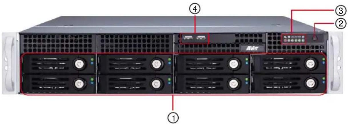
| 1 | HDD bay | 3 | LED indicator |
| 2 | Power button | 4 | USB port |
■ LED indicator table (from left to right on front panel)
| LED indicator | Description |
| Fan | ● Flash: It indicates a fan failure. ● Continuously on: It indicates an overhead condition. |
| Power Failure | Flash: it indicates a power failure. |
| LAN 2 | Flash: it indicates network activity on LAN 2 port. |
| LAN 1 | Flash: it indicates network activity on LAN 1 port. |
| HDD Device | Flash: it indicates IDE channel activity in SATA drive, SCSI drive, or DVD-ROM drive. |
| Power | It indicates power supply is normal. |
1.3 Back Panel
P5036-R
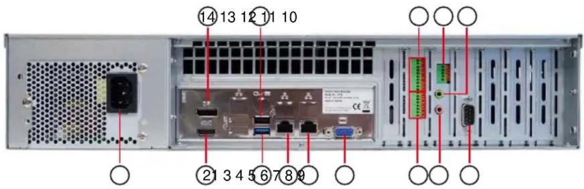
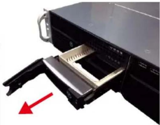
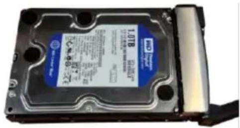
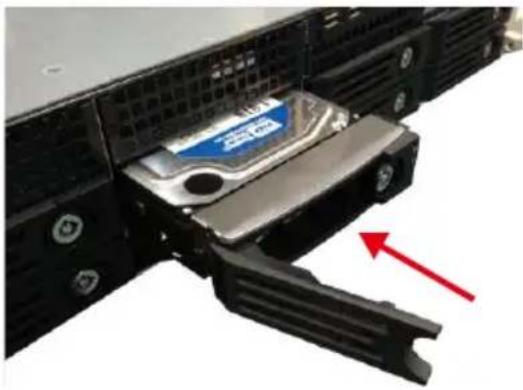
The NVR/DVR unit can support up to 8 SATA hard disks to install inside HDD bay. Follow the instructions below to install the hard disk:
- Open the door of HDD bay.
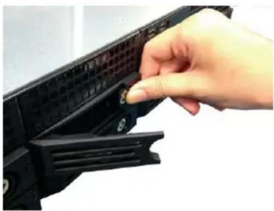
natural_image
Hand inserting a small component into a black plastic device panel (no text or symbols visible)- Lose the screw on both side of HDD and remove the plastic box from HDD bay.
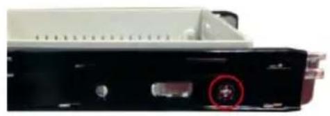
natural_image
Close-up of a black electronic device rear panel with a red circular marker highlighting a component (no visible text or symbols)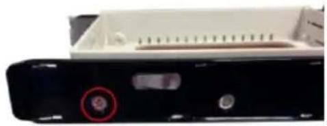
natural_image
Close-up of a black electronic device rear panel with a red circular marker and two buttons (no visible text or symbols)- Pull out the HDD bay.
natural_image
Close-up of a black server rack with a metal drawer and a red arrow pointing to a component (no text or symbols visible)- Place the hard disk inside the HDD bay and align the hard disk's screw hole with screw hole of HDD bay. And, secure the hard disk (both side).
natural_image
Close-up of a hard disk drive with visible label and cable (no readable text or symbols)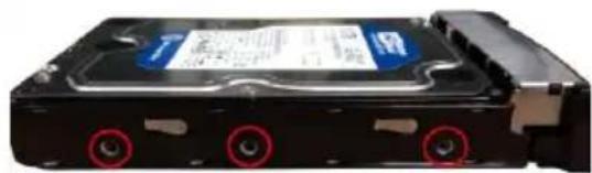
natural_image
Close-up of a black hard drive chassis with three red circular mounting holes (no visible text or symbols)- Slide HDD bay back to NVR/DVR unit and push to close the door of HDD bay. User can lock the HDD drawer by using the key that is included in accessories kit.
natural_image
Close-up of a server rack with a blue-labeled internal component and a red arrow pointing to a disassembly mechanism (no text or symbols visible)- User may now connect all the cables and power on the NVR/DVR unit.
1.4.1 Install Internal Hard Disk
The NVD/DVR unit can support up to 2 internal SATA hard disks. Follow the instructions below to install the hard disk:
-
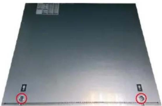
Un-screw the cover case (both side) and open the cover case of NVR/DVR unit. Push the button (as red circle mark) and follow the arrow direction to push and open the cover case.
-
Remove the tape on SATA cable.
natural_image
Plain metallic surface with two small circular markers and a red circle highlighting the center (no text or symbols)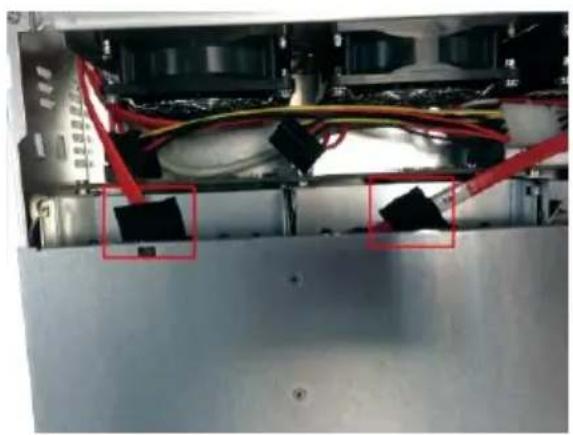
natural_image
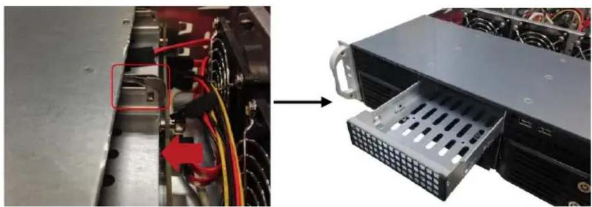
Interior view of an electronic device showing exposed wiring and components (no visible text or symbols)- Release the tenon and push the hard disk box forward at the same time to take out the hard disk box.
natural_image
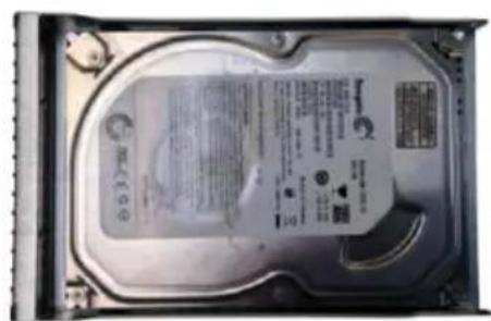
Close-up of an electronic device showing internal wiring and a server rack with a grid socket (no visible text or symbols)- Place the hard disk inside the hard disk box and align the hard disk's screw hole with screw hole of hard disk box. And, secure the hard disk (both side).
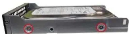
natural_image
Close-up of a gray internal hard drive with two red circular markers indicating mounting points (no visible text or symbols)- Slide hard disk box back to NVR/DVR unit
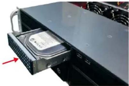
natural_image
Close-up of a server rack with an open hard drive showing internal components (no visible text or symbols)-
Close cover case of NVR/DVR unit and secure the cover case.
-
Connect the SATA cable and power cable to hard disk.
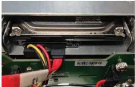
natural_image
Close-up of an electronic device showing internal components and wiring (no readable text or symbols)- User may now connect all the cables and power on the NVR/DVR unit.
1.5 Pin Definition of Sensor/Relay/RS485 Port
The I/O card enables you to connect 8 sensor inputs and 4 relay outputs. Just connect the external sensor and relay pin directly to the I/O card pinhole. Check the table below and locate which pinhole is assigned to sensor input and relay output.
The signal from the sensor (i.e., infrared sensors, smoke detectors, proximity sensors, door sensors, etc.) is being transmitted to the I/O card and this triggers the system to respond and send signal to relay device (i.e., alarm, telephone etc.).
■ RS485 Pin definition
When connect PTZ camera through RS485 interface, please refer to the following pin definition to connect the NVR/DVR and PTZ.
| Pin | NVR/DVR site | PTZ site |
| TX+ | RS485 TX+ signal | RS485 RX+ signal |
| TX- | RS485 TX- signal | RS485 RX- signal |
| RX+ | RS485 RX+ signal | RS485 TX+ signal |
| RX- | RS485 RX- signal | RS485 TX- signal |

If user uses the 2 wires for the PTZ camera connection, please connect to the RS-485 TX+ and TX- of the NVR/DVR site.
■ Sensor Pin definition
| Pin | Definition | Pin | Definition |
| 1 | Sensor Signal 1 | 5 | Sensor Signal 5 |
| 2 | Sensor Signal 2 | 6 | Sensor Signal 6 |
| 3 | Sensor Signal 3 | 7 | Sensor Signal 7 |
| 4 | Sensor Signal 4 | 8 | Sensor Signal 8 |
■ Alarm Pin definition
| Pin | Definition | Pin | Definition |
| C1 | Relay Common 1 | C3 | Relay Common 3 |
| NO | Relay Normal Open | NO | Relay Normal Open |
| C2 | Relay Common 2 | C4 | Relay Common 4 |
| NO | Relay Normal Open | NO | Relay Normal Open |
Chapter 2 Main System Configuration
2.1 Getting Started
- Connect the power cable and mouse to NVR/DVR unit.
- Power on the NVR/DVR unit and wait for system start up processing to complete.
- For security purpose, the NVR/DVR system would require user to enter User ID and Password before it can be accessed. (If this is the first time, enter the default ID [admin] and password [admin]).
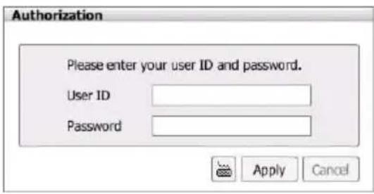
- After login successful, the preview UI is displayed.
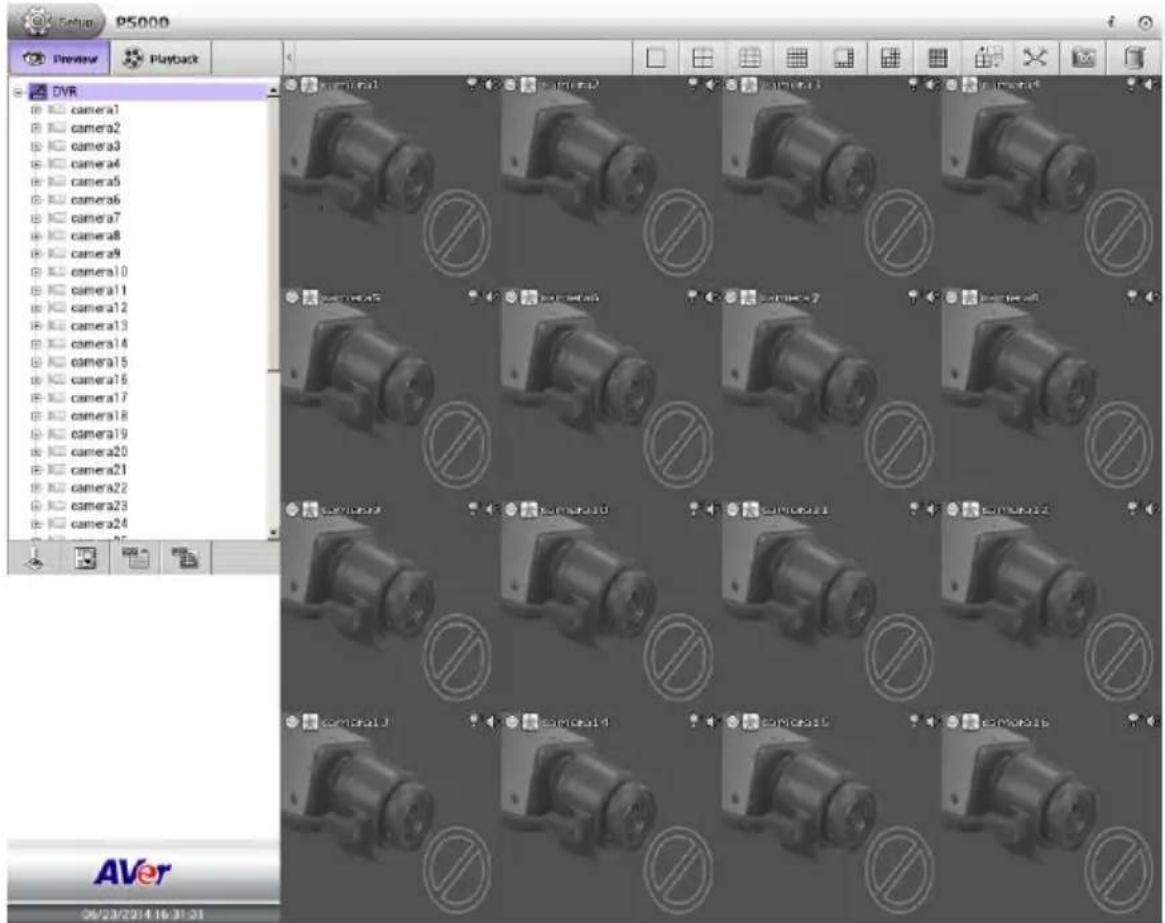
- Next, setup the following settings in order to start monitoring.
■ Setup System Date and Time: Setup the date and time in order to have corrected recording time and date. Please refer to Chapter 2.5.1.
■ Format Hard Disk: The hard disk must be formatted before use it to save recording data (see also Chapter 2.7.1).

Before formatting hard disk, please make sure no operations is running on NVR/DVR system.
■ Setup Storage Path: Select the hard disk to be a storage path for saving recorded video. Please refer to Chapter 2.7.2.
■ Network Setup: Setting up the NVR/DVR system's IP address that is same IP segment as your network. Please refer to Chapter 2.6.
■ Connect IP camera: Please refer to Chapter 2.8.
■ Setup Recording Schedule: Setting up the record schedule to start recording. Please refer to Chapter 2.9.
- For more detail configuration of NVR/DVR system, refer to the chapters in followings.
2.1.1 Familiarizing Icons on Dialog Box
There are some icons are shown on dialog box through the NVR/DVR system and they are explaining in followings.
| Expanding the dialog box on the screen. | |
| Closing the dialog box. |
2.2 Familiarizing Functions in Preview Mode
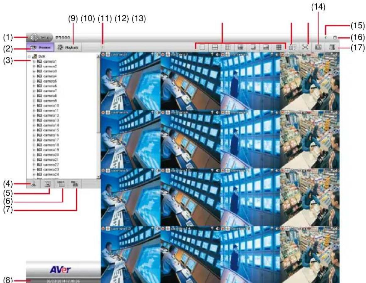
| Name | Function |
| (1) Setup | Click Setup button to configure settings for cameras, recording, network, scheduler, backup, sensors, relays, alarms and user authentication. |
| (2) Preview | Switch to Preview mode. This allows you to view live camera display. |
| (3) Camera list | Lists all cameras of NVR/DVR. Click + to expand the list. User can select and drag the camera to video display area to arrange the monitor layout(see also Chapter 3.1) |
| (4) PTZ | To call out a PTZ control panel and appoint PTZ camera (see also Chapter 2.8.4). |
| (5) EMap | To view the cameras, sensors, and relays on Emap (see also Chapter 3.7). |
| (6) Event Log Viewer | Search and display the record of activities that take place in the system (see also Chapter 2.17.1). |
| (7) POS Log Viewer | Search and display POS event logs (see also Chapter 2.16.3). |
| (8) Date and Time | It shows the current system date and time. |
| (9) Playback | Switch to Playback mode. This allows you to view the recorded video file. (see also Chapter 2.3) |
| (10) Hide button | To hide the side area and give more view of screen. |
| (11) Split Screen Mode | It provides 7 kinds of split display modes for your selection. User can select the split display modes by clicking the split mode icon. |

To only display one of the video in the multiple-screen mode, double click on the video screen you only want to display (see also Chapter 3.6).
| (12) AutoScan | Click it to start auto cycle display each channel (see also Chapter 3.11). |
| (13) Full screen | Use the entire area of the screen to only display the video. To return, press the right button of the mouse or ESC on the keyboard or click the arrow icon (see also Chapter 3.9). |
| (14) Snapshot | Catch a static recording image and save it as a JPG file in USB pen drive device(see also Chapter 3.8) |

Plug the USB pen drive into NVR/DVR unit before click Snapshot button.
| (15) System Information | Click it to view NVR/DVR system's version. |
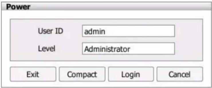
| (16) Power button | Call up the Power dialog box.In the Power dialog box, user may do the following: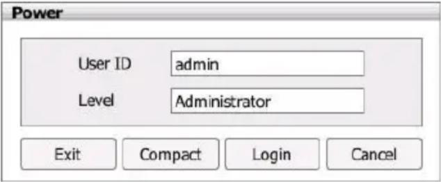 -Exit:To shutdown the NVR/DVR system.-Compact:Switch to compact mode. In compact mode, user's authority is limited (see also Chapter 2.4.1).-Login:To login in different account. Default user ID is admin and password is admin.-Cancel:To exit Power dialog box. -Exit:To shutdown the NVR/DVR system.-Compact:Switch to compact mode. In compact mode, user's authority is limited (see also Chapter 2.4.1).-Login:To login in different account. Default user ID is admin and password is admin.-Cancel:To exit Power dialog box. |
| Name | Function |
| (17) Alarm Log Viewer | Alarm log: To view and search the alarm event logs (see also Chapter 2.17.2). |
2.3 Familiarizing Functions in Playback Mode
Click playback tab to switch to playback mode.
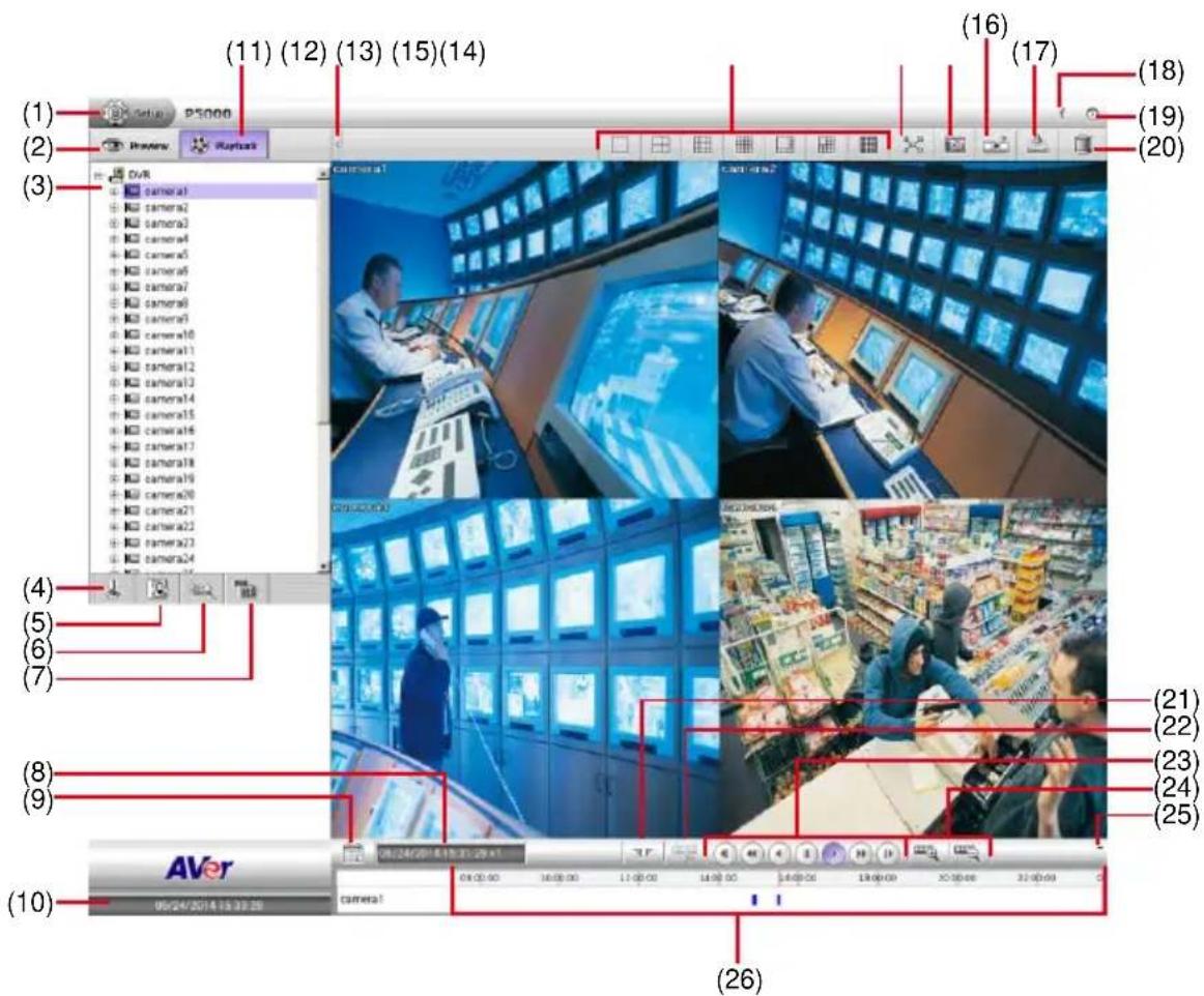
| Name | Function |
| (1) Setup | Click Setup button to configure settings for cameras, recording, network, scheduler, backup, sensors, relays, alarms and user authentication. |
| (2) Preview | Switch to Preview mode. This allows you to view live camera display. |
| (3) Camera list | Lists all cameras of NVR/DVR. Click + to expand the list. User can select and drag the camera to video display area to playback (see also Chapter 4.6.1). |
| (4) PTZ | In playback mode, the NVR/DVR system doesn’t support PTZ function. |
| (5) Emap | To view the cameras, sensors, and relays on Emap (see also Chapter 3.7). |
| (6) Search | NVR/DVR supports 2 type of searching in playback mode – Event Search and Visual Search.- Event Search: Search from the recorded activities that were recorded in event log such as Sensor, Motion, Video Loss (see also Chapter 4.3).- Visual Search: Search from a specific camera by Date, Hour, Minute, 10 Seconds and Second (see also Chapter 4.4). |
| (7) POS Log Viewer | Search and display POS event logs (see also Chapter 2.17.3). |
| (8) Status bar | Display the recorded date, time and play speed. |
| (9) Date | Select the date on the calendar and the time to where to start playing the recorded video file. |
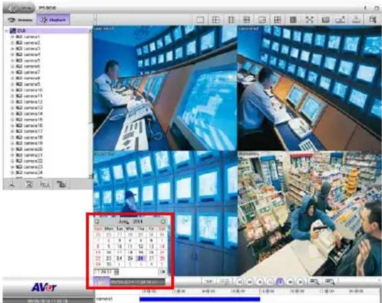
- Date: click the date on calendar to select. The date in bold text indicates there has recorded file. Click and icon to switch the date or click ▼ icon next to month to select the month. To switch the year, click on the text of year and click spin button to select.
- Time: In Time box, select the hour, minute, and second to setup the playback start up time.
| Sun | Mon | Tue | Wed | Thu | Fri | Sat |
| 25 | 26 | 27 | 28 | 29 | 30 | 31 |
| 1 | 2 | 3 | 4 | 5 | 6 | 7 |
| 8 | 9 | 10 | 11 | 12 | 13 | 14 |
| 15 | 16 | 17 | 18 | 19 | 20 | 21 |
| 22 | 23 | 24 | 25 | 26 | 27 | 28 |
| 29 | 30 | 1 | 2 | 3 | 4 | 5 |
| Name | Function |
| (10) Date and Time | It shows the current date and time. |
| (11) Playback | Switch to Playback mode. This allows you to view the recorded video file. |
| (12) Hide button | To hide the side area and give more view of screen. |
| (13) Split Screen Mode | Select from 7 kinds of split screen type to playback the recorded video file of all the camera, or one camera over the other or alongside on a single screen. |
 To only display one of the video in the multiple-screen mode, double click on the video screen you only want to display (see also Chapter 4.6.3). To only display one of the video in the multiple-screen mode, double click on the video screen you only want to display (see also Chapter 4.6.3). | |
| (14) Full screen | Use the entire area of the screen to only display the video. To return, press the right button of the mouse or ESC on the keyboard or click the arrow icon.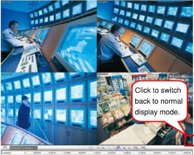 When you switch to full screen in multiple-screen mode, Left click to toggle to only display one of the video in the multiple-screen mode or all. When you switch to full screen in multiple-screen mode, Left click to toggle to only display one of the video in the multiple-screen mode or all. |
| (15) Snapshot | Catch a static recording image and save it as a JPG file in pen drive device (see also Chapter 4.6.7). |
| (16) Bookmark | Mark a reference point when reviewing the recorded video file to which you may return for later reference (see also Chapter 4.5). |
| (17) Backup | Save the playback file to USB pen drive (see also Chapter 2.12). |
| (18) System Information | Click it to view NVR/DVR system's version. |
| (19) Power button | Call up the Power dialog box.In the Power dialog box, user may do the following: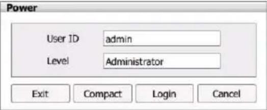 - Exit: Shutdown the NVR/DVR system.-Compact: Switch to compact mode. In compact mode, user's authority is limited (see also Chapter 2.4.2).-Login: To login in different account. Default user ID isadminand password isadmin.-Cancel: To exit Logout dialog box. - Exit: Shutdown the NVR/DVR system.-Compact: Switch to compact mode. In compact mode, user's authority is limited (see also Chapter 2.4.2).-Login: To login in different account. Default user ID isadminand password isadmin.-Cancel: To exit Logout dialog box. |
| (20) Alarm Log | Clickbutton to view and search the alarm event logs (see also Chapter 2.17.2). |
| (21) Segment | Keep a portion of the recorded video to repeat playback; also can output the segment video to the pen drive device.Click thebutton to set the segment video. User can drag the triangle mark to set the video segment (see also Chapter 4.6.6). |
| (22) | Save the segmented video file in *.mpg, *.avi, or *.dvr format (see also Chapter 4.6.6). |
| (23) Playback Control Buttons | From left to right order:◀ Previous: Go back to the previous frame.◀ Slower: Play the recorded video file at the speed of 1/2x, 1/4x, or 1/8x. The playback speed will show on the screen.◀ Rewind: Wind back the recorded video file.Ⅱ Pause: Briefly stop playing the recorded video file.▶ Play: Play the recorded video file.▶ Faster: Play the recorded video file at the speed of 2x, 4x, 8x, 16x, 32x, or 64x. The playback speed will show on the screen.▶ Next: Go to the next frame. |
(24) 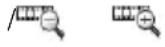 (Zoom in/ out) (Zoom in/ out) | To expand the playback time bar from an hour to minute. |
| (25) Minimize | Click to close up the progress bar. Click again to open up. |
| (26) Progress bar | Show the progress of the file being played. You may move the bar to seek at any location of the track.Using the Zoom In/Out button to expand the playback time from an hour to minute. Meaning of color in progress bar:- Green: Motion record- Blue: Always record(normal record)- Yellow: Video loss- White: No record data Meaning of color in progress bar:- Green: Motion record- Blue: Always record(normal record)- Yellow: Video loss- White: No record data |
2.4 Compact Mode
The preview and playback are both supported compact mode. To switch to Compact mode, click power button (located at upper right corner) and select Compact button in Power dialog in preview or playback mode.
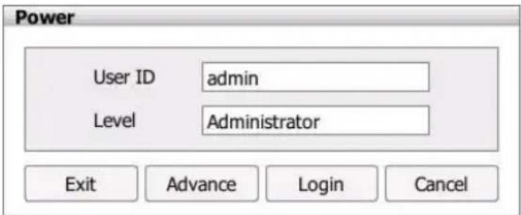
To switch back to Advance mode, click power button and select Advance button in preview or playback mode.
The following chapters will describe the function buttons on preview and playback compact mode.
2.4.1 Familiarizing Function in Preview Compact Mode
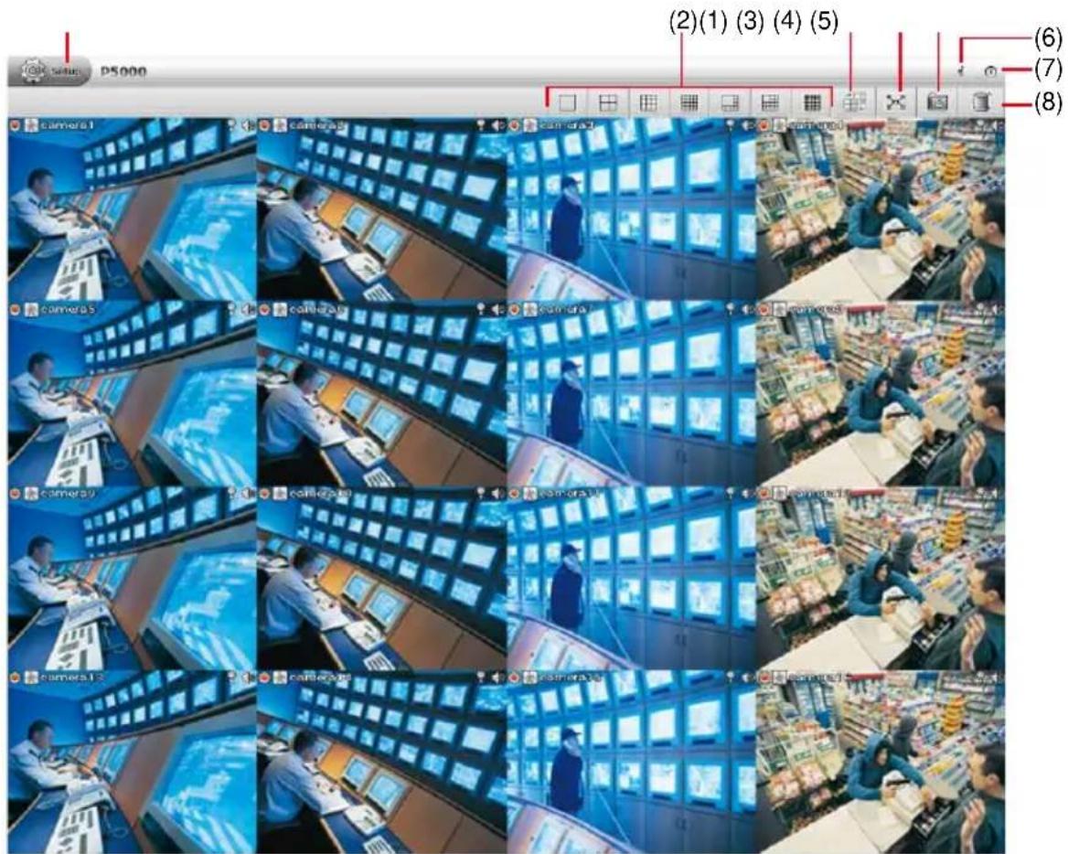
| Name | Function |
| (1) Setup | Click Setup button to configure settings for cameras, recording, network, scheduler, backup, sensors, relays, alarms and user authentication. |
| (2) Split Screen Mode | It provides 7 kinds of split display modes for your selection. User can select the split display modes by clicking the split mode icon. |
 | - When the NVR/DVR system is in multiple-screen mode, user can click the video screen of the camera and Drag on where user wants to relocate it.- To only display one of the video in the multiple-screen mode, double click on the video screen user only wants to display. |
| (3) AutoScan | Click it to start auto cycle display each channel. |
| (4) Full screen | Use the entire area of the screen to only display the video. To return, click the arrow icon at bottom of right.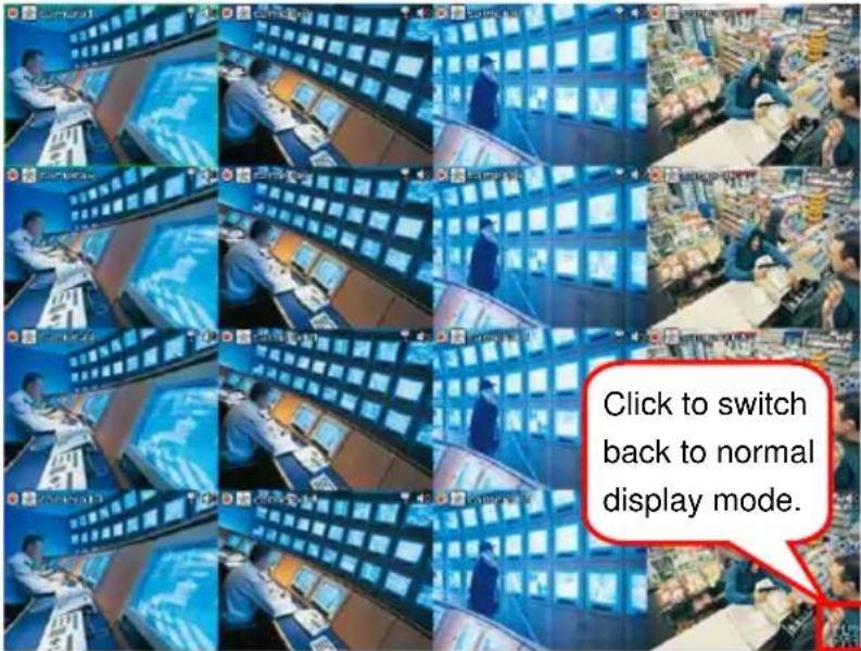 When you switch to full screen in multiple-screen mode, Left click to toggle to only display one of the video in the multiple-screen mode or all. When you switch to full screen in multiple-screen mode, Left click to toggle to only display one of the video in the multiple-screen mode or all. |
| (5) Snapshot | Catch a static recording image and save it as a JPG file in USB pen drive device (see also Chapter 3.8). |
| (6) System Information | Click it to view NVR/DVR system's version and copyright. |
| (7) Power button | Call up the Power dialog box.In the Power dialog box, user may do the following: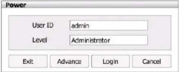 -Exit:To shutdown the NVR/DVR system.-Advance:Switch to preview advanced mode.-Login:To login in different account. Default user ID is admin and password is admin.-Cancel:To exit Power dialog box. -Exit:To shutdown the NVR/DVR system.-Advance:Switch to preview advanced mode.-Login:To login in different account. Default user ID is admin and password is admin.-Cancel:To exit Power dialog box. |
| (8) Alarm Log Viewer | Clickbutton to view and search the alarm event logs (see also Chapter 2.17.2). |
2.4.2 Familiarizing Function in Playback Compact Mode
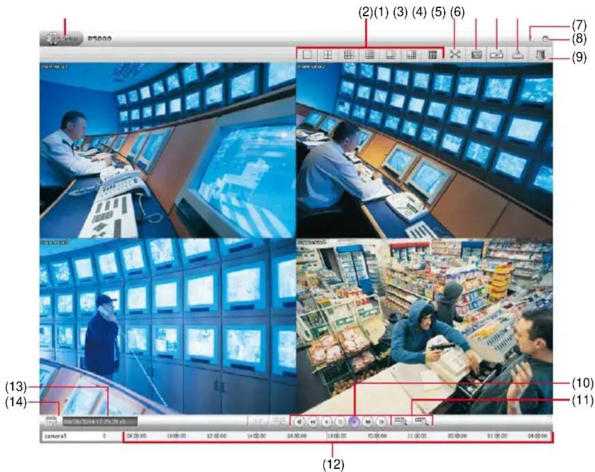
| Name | Function |
| (1) Setup | Click Setup button to configure settings for cameras, recording, network, scheduler, backup, sensors, relays, alarms and user authentication. |
| (2) Split Screen Mode | It provides 7 kinds of split display modes for your selection. User can select the split display modes by clicking the split mode icon. |
 | - When the NVR/DVR system is in multiple-screen mode, user can click the video screen of the camera and Drag on where user wants to relocate it.- To only display one of the video in the multiple-screen mode, double click on the video screen user only wants to display. |
| (3) Full screen | Use the entire area of the screen to only display the video. To return, press the right button of the mouse orESCon the keyboard or click the arrow icon.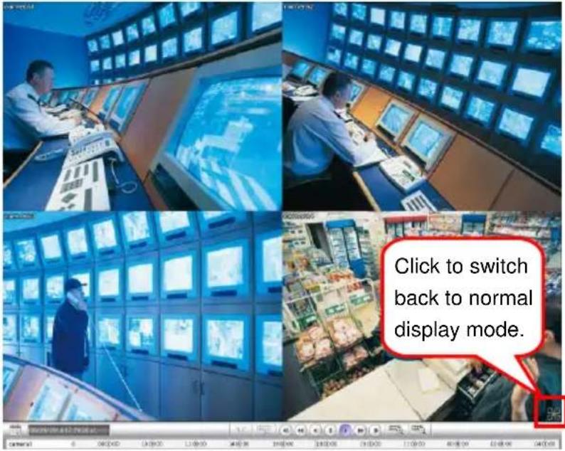 When you switch to full screen in multiple-screen mode, Left click to toggle to only display one of the video in the multiple-screen mode or all. When you switch to full screen in multiple-screen mode, Left click to toggle to only display one of the video in the multiple-screen mode or all. |
| (4) Snapshot | Catch a static recording image and save it as a JPG file in USB pen drive device.1. Select the channel or all channels.2. Plug the USB pen drive to NVR/DVR unit.3. ClickSnapshot( )button.4. In Snapshot dialog box, check the Save path has been detected by NVR/DVR system. If the save path doesn't found, clickRescan Devicebutton to re-detect it.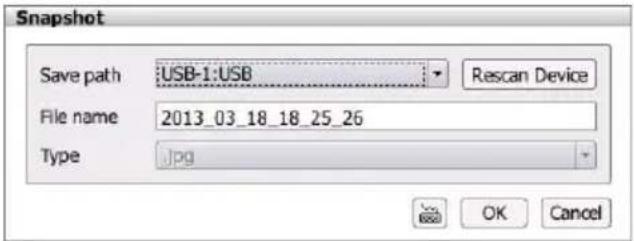 5. If user wants to re-name theFile name, call out the virtual keyboard and enter the new file name in File name column.6. ClickOKto capture and save the screen shot.7. The captured and saved screen image can be viewed on PC. 5. If user wants to re-name theFile name, call out the virtual keyboard and enter the new file name in File name column.6. ClickOKto capture and save the screen shot.7. The captured and saved screen image can be viewed on PC. |
| (5) Bookmark | Mark a reference point when reviewing the recorded video file to which you may return for later reference (see also Chapter 4.5). |
| (6) Backup | Save the playback file to USB pen drive (see also Chapter 2.11). |
| (7) System Information | Click it to view NVR/DVR system's version and copyright. |
| (8) Power button | Call up the Power dialog box.In the Power dialog box, user may do the following: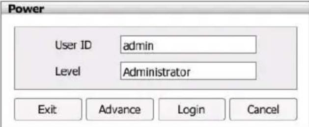 - Exit: To shutdown the NVR/DVR system.- Advance: Switch to playback advanced mode.- Login: To login in different account. Default user ID is admin and password is admin.- Cancel: To exit Power dialog box. - Exit: To shutdown the NVR/DVR system.- Advance: Switch to playback advanced mode.- Login: To login in different account. Default user ID is admin and password is admin.- Cancel: To exit Power dialog box. |
| (9) Alarm Log | Click button to view and search the alarm event logs (see also Chapter 2.17.2). |
| (10) Playback Control Buttons | From left to right order:◀ Previous: Go back to the previous frame.◀ Slower: Play the recorded video file at the speed of 1/2x, 1/4x, or 1/8x. The play speed will show on the screen.◀ Rewind: Wind back the recorded video file.∥ Pause: Briefly stop playing the recorded video file.▶ Play: Play the recorded video file.▶ Faster: Play the recorded video file at the speed of 2x, 4x, 8x, 16x, 32x, or 64x. The play speed will show on the screen.▶ Next: Go to the next frame. |
| (11) Zoom in/Zoom out) | To expand the playback time bar from an hour to minute. |
| (12) Progress bar | Show the progress of the file being played. You may move the bar to seek at any location of the track.Using the Zoom In/Out button to expand the playback time from an hour to minute. |
| (13) Status bar | Display the recorded date, time and play speed. |
| (14) Date | Select the date on the calendar and the time to where to start playing the recorded video file.-Date:click the date on calendar to select. The date in bold text indicates there has recorded file. Click and icon to switch the date or click ▼ icon next to month to select the month. To switch the year, click on the text of year and click spin button to select.-Time:In Time box, select the hour, minute, and second to setup the playback start up time.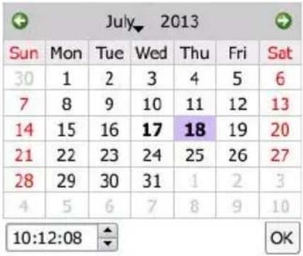 |
2.5 System Setup
Click Setup tab in preview/playback mode to switch to system setup mode.
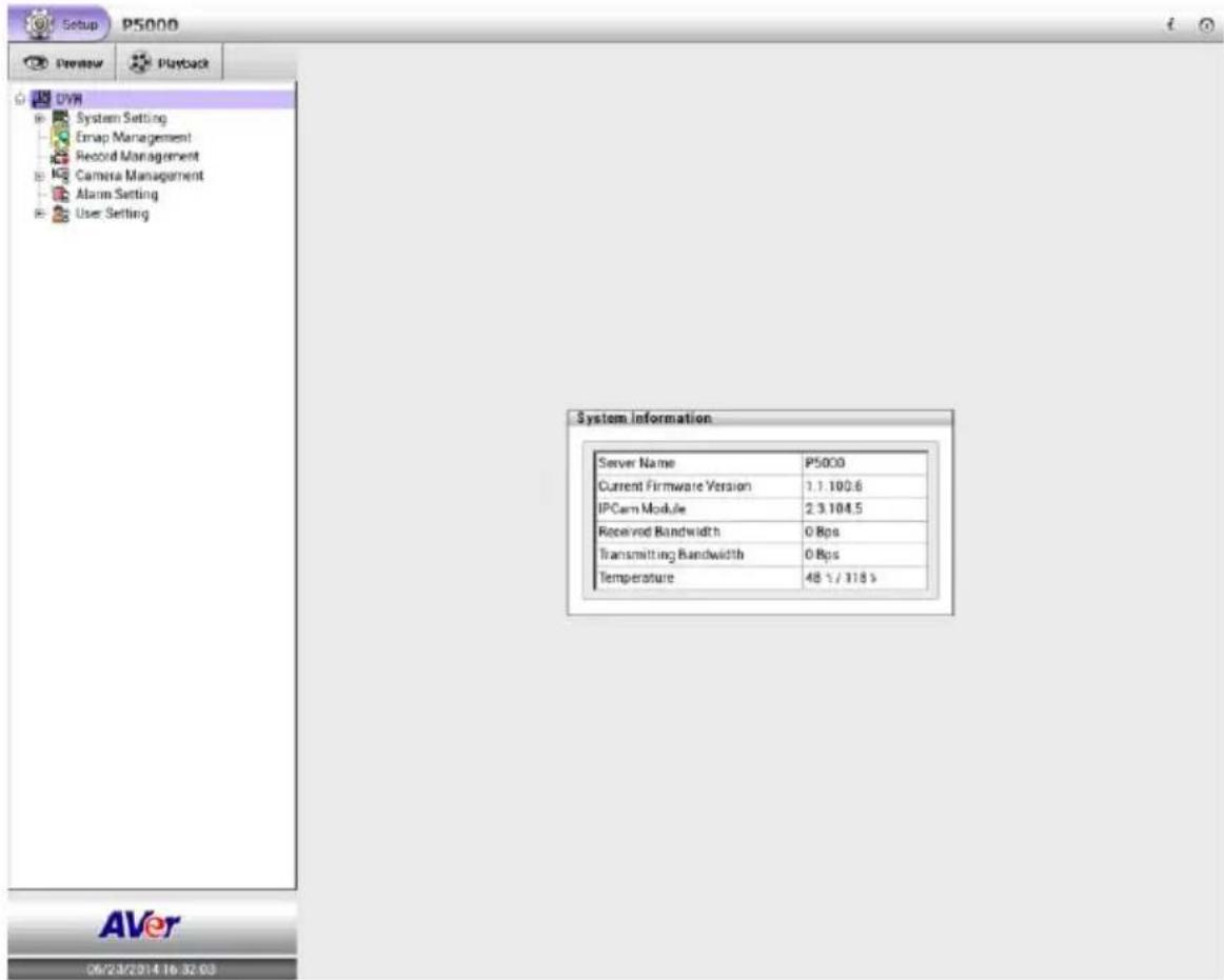
In Setup mode, user should see the System Information dialog box is displayed at the first place. In System Information dialog box, it displays the setting options of Language, Date/Time, Network1, Netowrk2 and Storage.
The setup sections are divided into System Setting, Emap Management, Record Management, Camera Management, Alarm Setting, User Setting, and Schedule Setting.
In the following chapters will describe all setup.
2.5.1 General System Setting
Setup the language of NVR/DVR system, video type, system date and time, synchronize the system time. Click Setup tab > System Setting; click + to expand list of System Setting and click System Configuration. After changing the settings, click Apply button to save the settings. To un-save the new settings, click Cancel button.
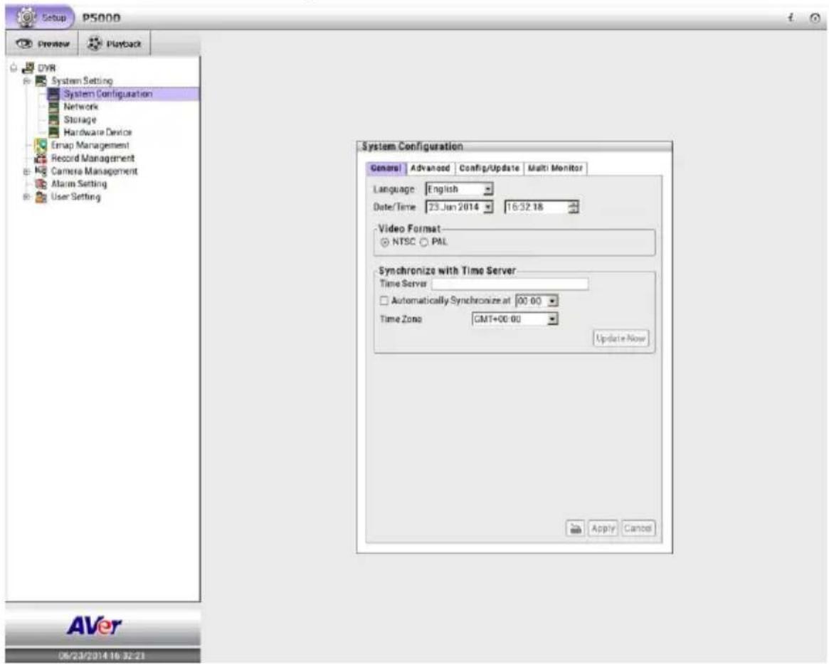
■ Language: Customize the system to display the tool tips and dialogs based on the selected language. By default the language is in English.
■ Video Format: Change and select the proper video system according to your camera video system. If the video system setting is wrong, the video would appear abnormal.
■ Date/Time: Select the date and time where NVR/DVR is located. Click 🧑 and ➕ icon to switch the month or click ▼ icon next to month to select the month. To switch the year, click on the text of year and click spin button to select.
■ Synchronize with Time Server: Adjust the NVR/DVR system time same as network time server.
Time Server: Fill in the Time Server IP address or domain name.
➢ Automatic synchronize at: Select Automatic Synchronize time to set automatic synchronize time on a daily basis.
Update Now: User can click Update Now button to adjust time right away.
2.5.2 System Advanced Setting
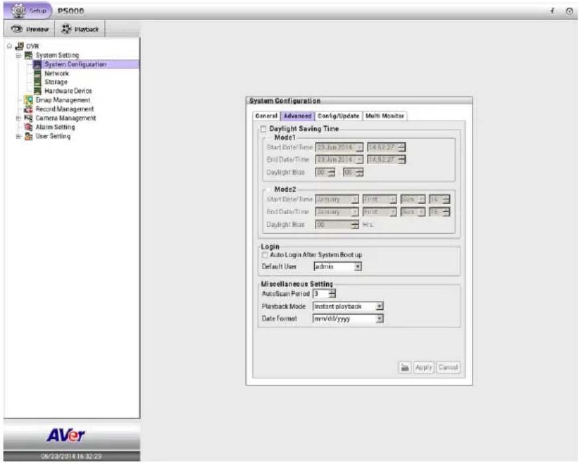
In Advanced of System Configuration, user can setup the daylight saving time, system login setting, and some other system related setting.
Click Setup tab > System Setting; click + to expand list of System Setting and click System Configuration > Advanced tab.
After changing the settings, click Apply button to save the settings. To un-save the new settings, click Cancel button.
2.5.2.1 Daylight Saving Time Setting
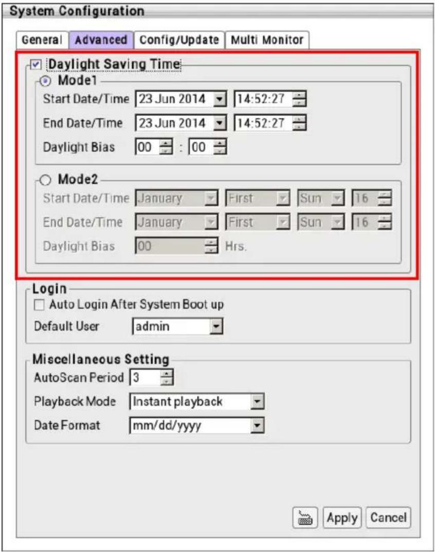
User can setup daylight saving mode as user is desired.
- Select the mode of Daylight saving.
➢ Mode 1: Mode 1 is setting up specific start date/time and end date/time.
Mode 2: Mode 2 is setting up fixed day of month in every year for start and end date/time.
- Setup the Star Date/Time and End Date/Time for Daylight saving period.
- Daylight Bias: Assign a time that it is for daylight saving time offset in your time zone. For example: if the time zone is in U.S. Eastern, the time offset is 1 hour.
- Click Apply to save the setting.
2.5.2.2 Customizing System Login Setting
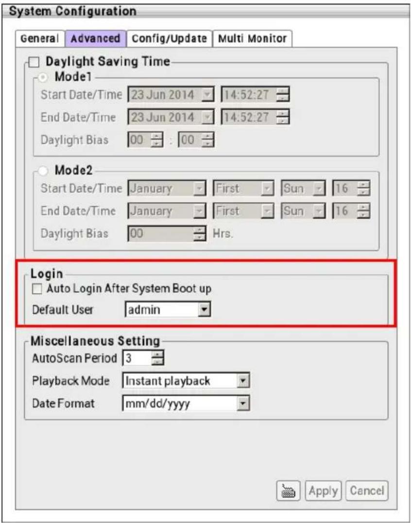
Enable the conditions in Login section you want the system to automatically carry out. Click Apply to save the setting.
■ Auto Login after system boot up: Login NVR/DVR system automatically when NVR/DVR operating system is started.
■ Default user: Automatically log in to the selected default user when the NVR/DVR system is executed.
2.5.3.3 Customizing System Miscellaneous Setting
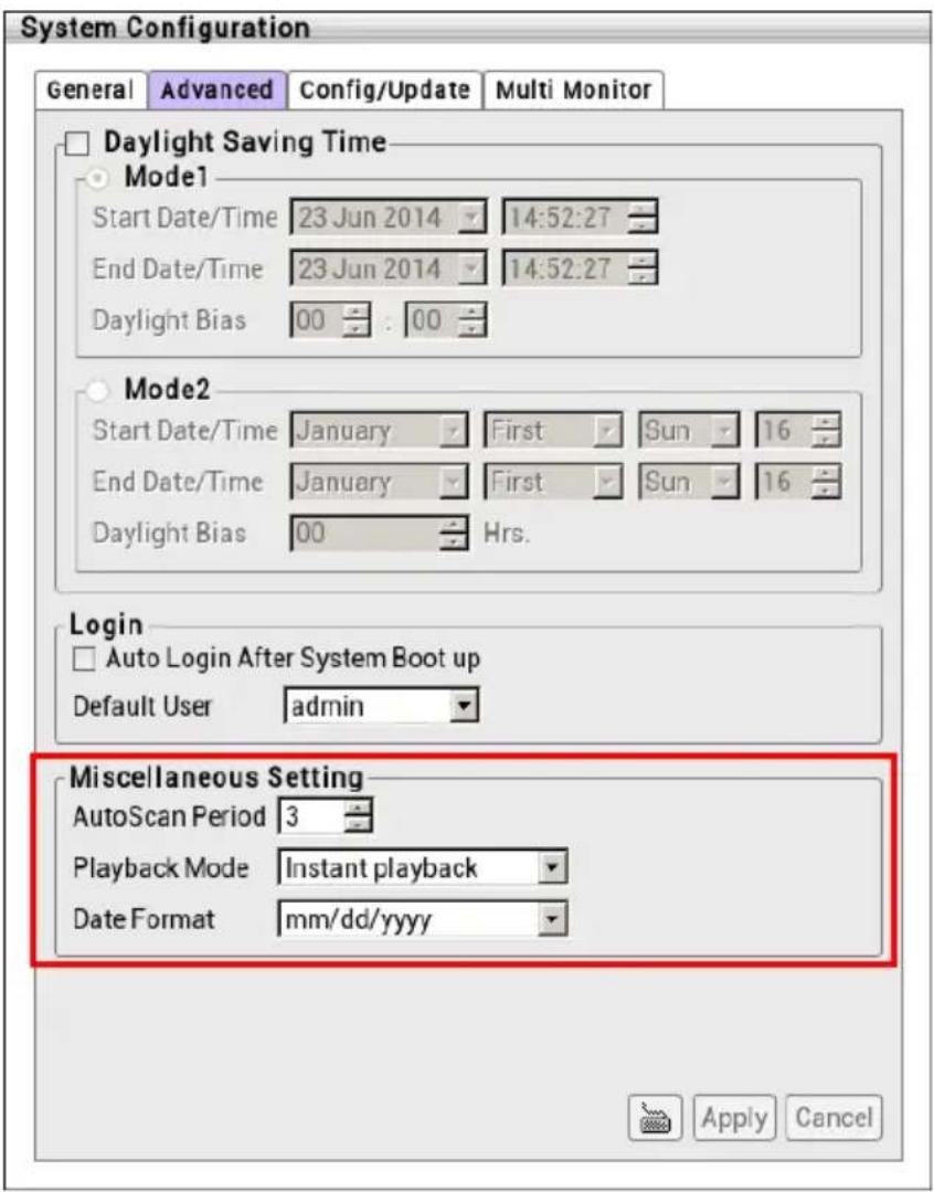
Enable the conditions in Miscellaneous section you want the system to perform. Click Apply to save the setting.
■ Auto Scan Period: Set the time gap of the Auto Scan function from 3 to 10 seconds. This automatically switches to the next video in cycle depending on the set time gap.
■ Playback Mode:
Select the mode of playback the video.
√ Select date and time: Select the date and time which user wants to playback.
√ Play the last file: Automatically playback the video from the last hour
√ Instant Playback: Automatically playback the video which has just recorded.
■ Date Format: Select the date format which wants to display in Select date and time playback mode
2.5.4 Update/Export/Import
In Configure Update, user can import the backup configure file to NVR/DVR system and export the configure file to external USB pen drive. Also, user can update the NVR/DVR system's firmware and IP camera patch file.
Click Setup tab > System Setting; click + to expand list of System Setting and click System Configuration > Configure/Update tab.
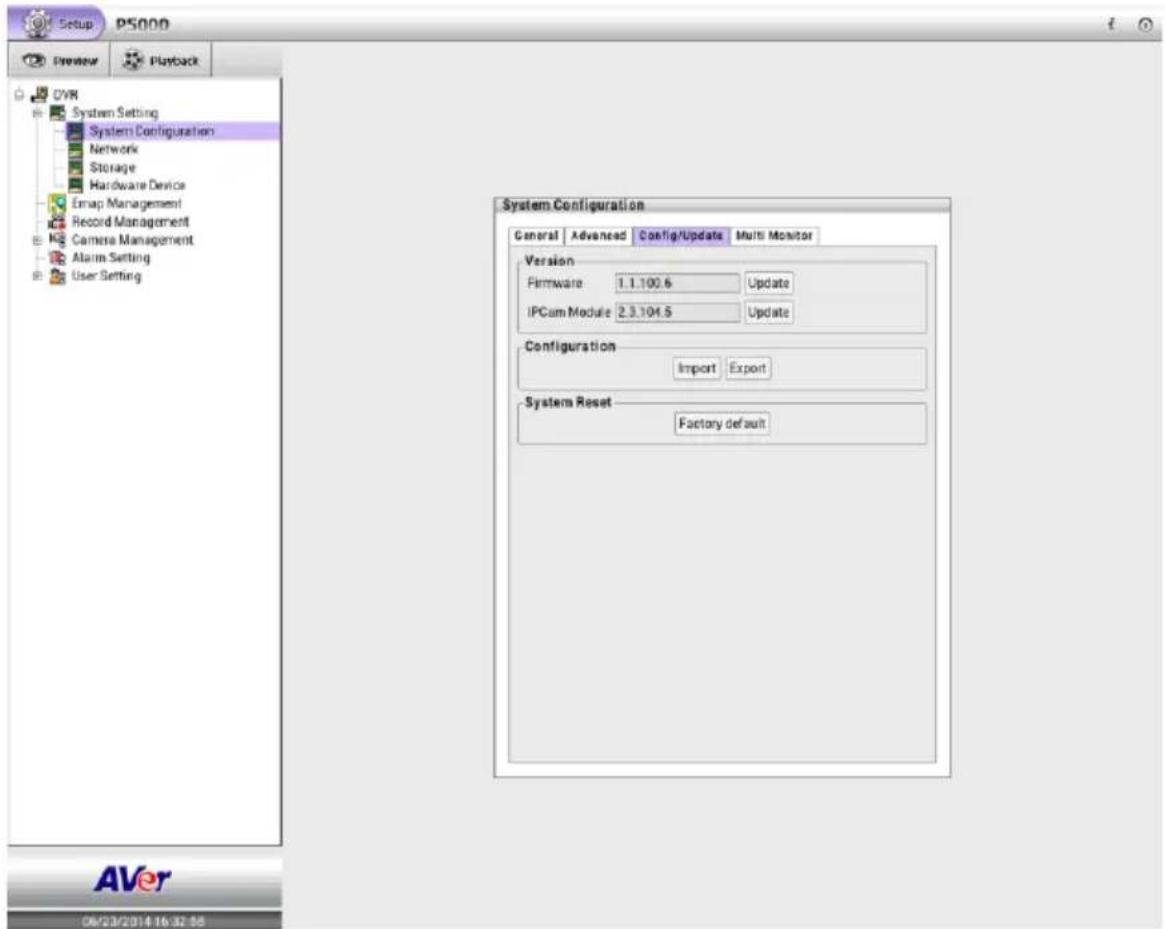
2.5.4.1 Importing NVR/DVR System Configuration
To regain the same settings back from previously backup configuration file.
- Plug the USB pen drive into the NVR/DVR unit that contains the backup configuration file that user has exported previously.
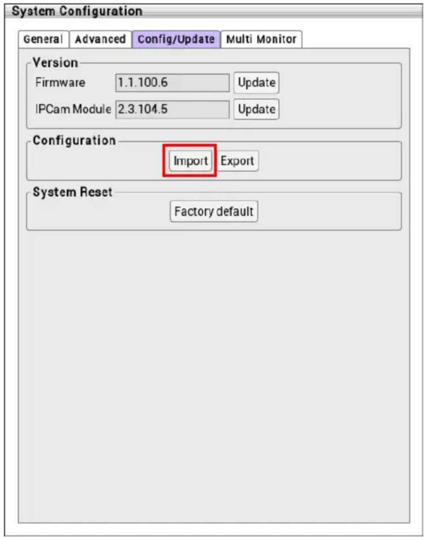
- In Configure/Update page, click Import button in Configuration section.
- In Import dialog box, user should see the backup configuration file path and file name.
- Then, click Import button.
- A message dialog box will appear to remind user that the NVR/DVR system will reboot after restoring the backup configuration file. Click OK button to continue. To cancel click Cancel button.
- After restoring backup configuration file, a message dialog box will appear to inform user that import process is completed. Click OK button and the NVR/DVR system will reboot.
2.5.4.2 Exporting NVR/DVR System Configuration
Backup a copy of all the settings and allows you to regain the same settings back.
- Plug in the USB pen drive for saving configuration file.
- In Configure/Update page, click Export button in Configuration section.
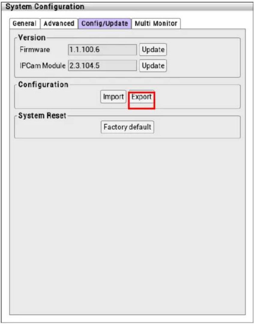
- In Export dialog box, user should see the backup configuration file path and default backup configuration file name.
- Next, click Export button.
- A message dialog box will appear to notice user that export process is completed. Click OK button to finish the export process.
- To restore the backup configuration file to NVR/DVR system, refer to Chapter 2.5.4.1.
2.5.4.3 Upgrading NVR/DVR Firmware
To update the firmware of NVR/DVR system.
- Plug the USB pen drive that contains the NVR/DVR firmware file. To get the newest NVR/DVR firmware, go to website http://www.aver.com > Support > Download center.
- In Configure/Update page, click Update button of Firmware.
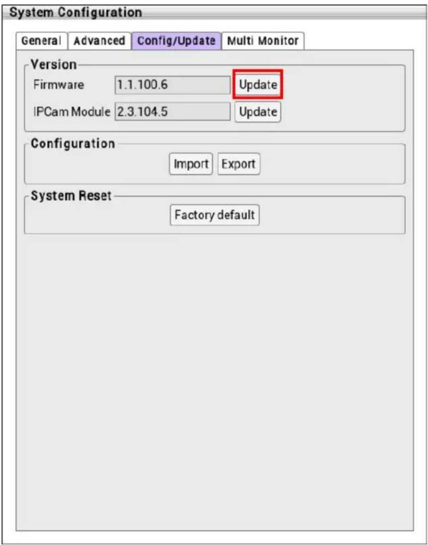
- In upgrade dialog box, the NVR/DVR system will detect the firmware file and shows the firmware file path, firmware file name, and version information.
- Click Upgrade button and an upgrade process dialog box will appear.
- A message dialog box will appear to inform user that the upgrade process is completed. Click OK button to restart the NVR/DVR system.
2.5.4.4 Upgrading IP Camera Module Patch
To update the firmware of NVR/DVR system.
- Plug the USB pen drive that contains the IP camera patch file.
- In Configure/Update page, click Update button of IPCam Module.
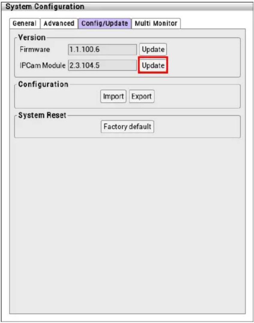
- In upgrade dialog box, the NVR/DVR system will detect the patch file and show the path of patch file, patch's file name, and version information.
- Click Upgrade button and an upgrade process dialog box will appear.
- A message dialog box will appear to inform user that the upgrade process is completed. Click OK button to finish the upgrade process.
2.5.5 Setup Dual Monitor
The NVR/DVR system support dual monitor connection. User can choose the function UI to display on second monitor.

In default, the main monitor is the monitor connect on HDMI port.
- Click Setup tab > System Setting; click + to expand list of System Setting and click System Configuration > Multi Monitor tab.
- Select the function UI that wants to display on Monitor 2.
- Click Apply to save the setting.
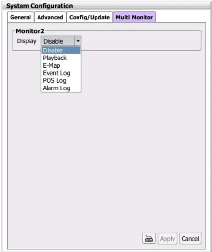
- Click Switch Control Monitor button can change control to another monitor. User can operate the function on another monitor.
2.5.6 Reset to Factory Default
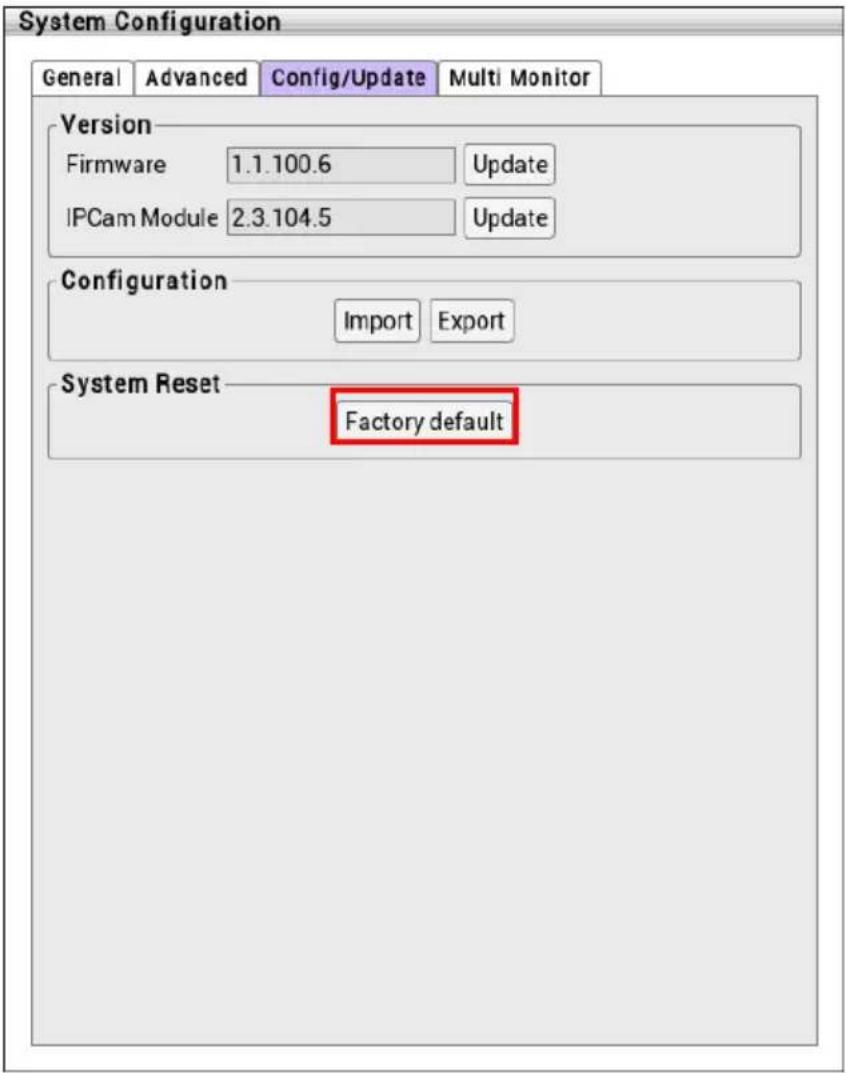
Reset the NVR/DVR system back to factory default value. All configurations will be lost after reset to factory default.
Click Apply button of Factory default and NVR/DVR system will reboot automatically.
2.6 Network Setting
Select type of IP mode, setup the IP address of NVR/DVR, and configure the DDNS.
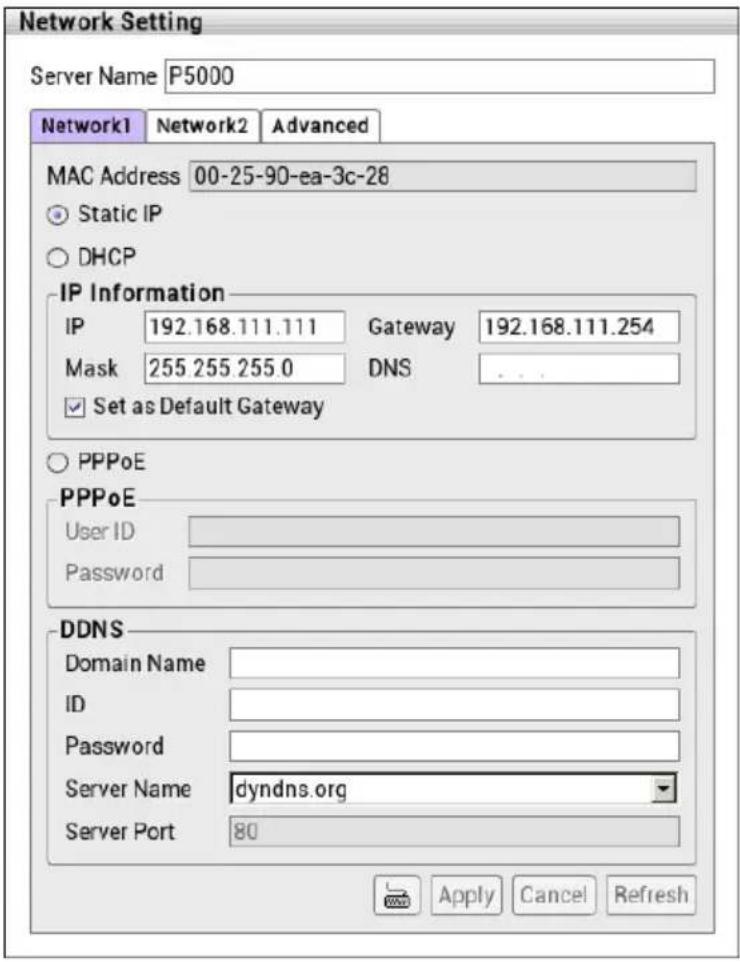
- Click Setup tab > System Setting; click + to expand list of System Setting and click Networking.
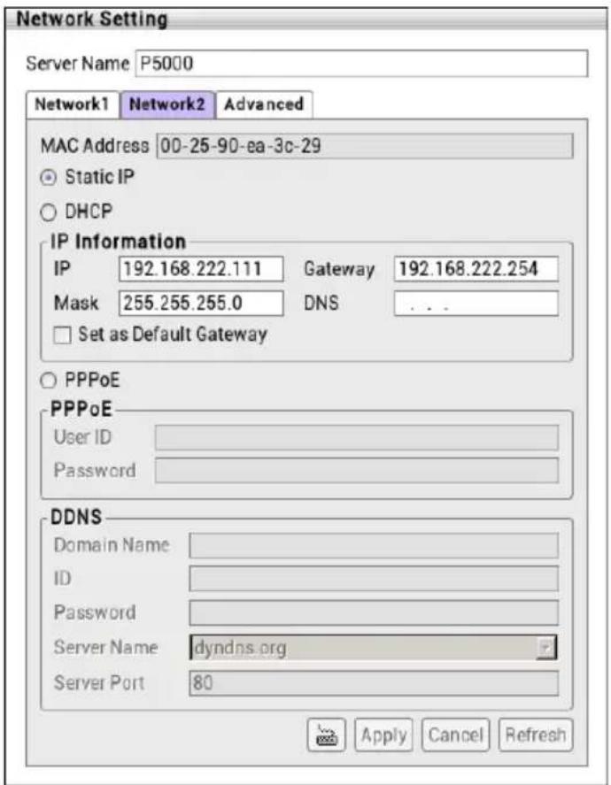
- MAC Address: Displays the MAC address of Ethernet port on LAN card.
- Select the IP mode – Static IP, DHCP, PPPOE.
Static IP: Assign a fixed IP address for NVR/DVR server
- IP ADDRESS: Assign a constant IP address which a real IP addresses given from ISP.

Do Not assign the NVR/DVR server to 1.0.0.0 network segment. It will because the NVR/DVR cannot access to Internet due to the un-recognize to 1.0.0.0 IP segment.
- Mask: It is a bitmask used to identify the sub network and how many bits provide room for host addresses. Enter the subnet mask of the IP address which user has assigned to NVR/DVR system.
- GATEWAY: A network device act as a passageway to internet. Enter the network
gateway IP address
- DNS: Domain Name Server translates domain names (such as www.abb.com.tw) to IP addresses. Enter the IP address of DNS if it is available.
DHCP: Uses DHCP server assigning NVR/DVR server an IP address.
PPPOE: Point-to-Point Protocol over Ethernet is a network protocol for encapsulating PPP frames in Ethernet frames. It is used mainly with ADSL services. If your network is using ADSL service connecting to internet, and then, select PPPOE mode. Enter User ID and Password that is given by your ISP for PPPOE connecting authority.
- Set as default gateway: The NVR/DVR system supports dual LANs, but only one LAN port can be set as default gateway.
- Setup the DDNS. To use this feature, register your own domain name server first. Only the LAN port is set as default gateway can be set DDNS function.
Domain Name: The user has applied on DDNS website.
ID: The account ID that user has created on DDNS website.
➢ Password: The password that user has setup on DDNS website.
Server Name: The domain name server that user has applied the domain name.
Server Port: The port is use to connect the domain name server.
-
After enter all necessary information, click Apply button to save the settings.
-
To setup the Network 2, click Network 2 tab and follow above steps.
2.6.1 Setup NVR/DVR Server Name
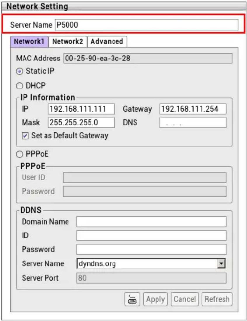
Assign a name for the NVR/DVR system. Alphabet letters and numbers only.
- Click Setup tab > System Setting; click + to expand list of System Setting and click Networking. User will see the Network Setting dialog box appear.
- Enter the desire name in Server Name column, then, click Apply button to save the settings.
2.6.2 Network Advanced Setting
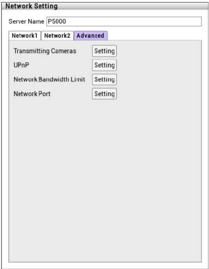
User can setup camera transmitting, UPnP function, bandwidth limit setting, and network port setting.
Click Setup tab > System Setting; click + to expand list of System Setting and click Networking > Advanced tab.
Click Setting to configure.
2.6.2.1 Setup Transmitting Camera
Select and click on the camera number in the Transmitting Camera section you want to make it accessible via internet using PCViewer, Remote site control, and iPhone/Andorid Viewer. To select all the cameras, enable the ALL check box.
2.6.2.2 Setup UPnP
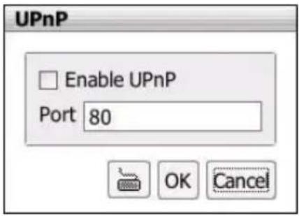
Assign a port number for UPnP service. Click OK to save the setting.
This function is working when the router had enabled the UPNP function and had opened the port, which had assigned for UPNP setting, for the NVR/DVR system.
2.6.2.3 Setup Bandwidth Limit
Set the network bandwidth consumption limit for remote accessing. Click OK to save the setting.
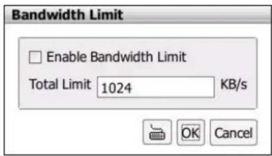
2.6.2.4 Setup Network Port
Assign a Network Port for remote accessing connection.
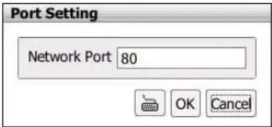
2.7 Storage Setting
In storage setting, user can add the storage path, remove the storage path, format hard disk, and set the hard disk recycle time.
Click Setup tab > System Setting; click + to expand list of System Setting and click Storage.
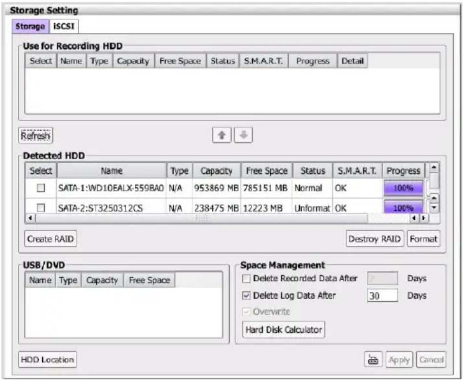
In Storage page, click HDD Location button can view the each HDD bay number. To exit, click Cancel button.
2.7.1 Formatting Hard Disk
Follow the steps below to format the hard disk for first time installation or re-format the hard disk to the type that can be saved recording video.
- In Storage Setting page, click Storage tab.
- In Storage Setting page, user should see the hard disk in Detected HDD section that NVR/DVR system has detected.

If the installed hard disk drive doesn't show in Free HDD list section, click Scan to re-detect it.
- Select the hard disk from Detected HDD section and click Format button.
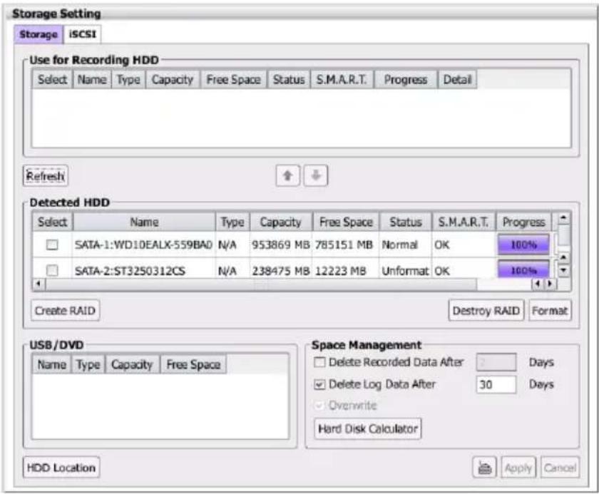
- Click Yes to confirm the format process.
- User will see the format process bar in percentage. When the format process is done, the percentage is displayed in 100% and click OK to complete the format process.

- After formatting, the hard disk is ready to set as a storage path.
2.7.2 Creating RAID Drive
RAID (redundant array of independent disks) is a storage technology that combines multiple disk drive components into a logical unit for the purposes of data redundancy and performance improvement.
The NVR/DVR system supports RAID 0, RAID 1, and RAID 10. Each RAID description is shown when user chooses the RAID type.
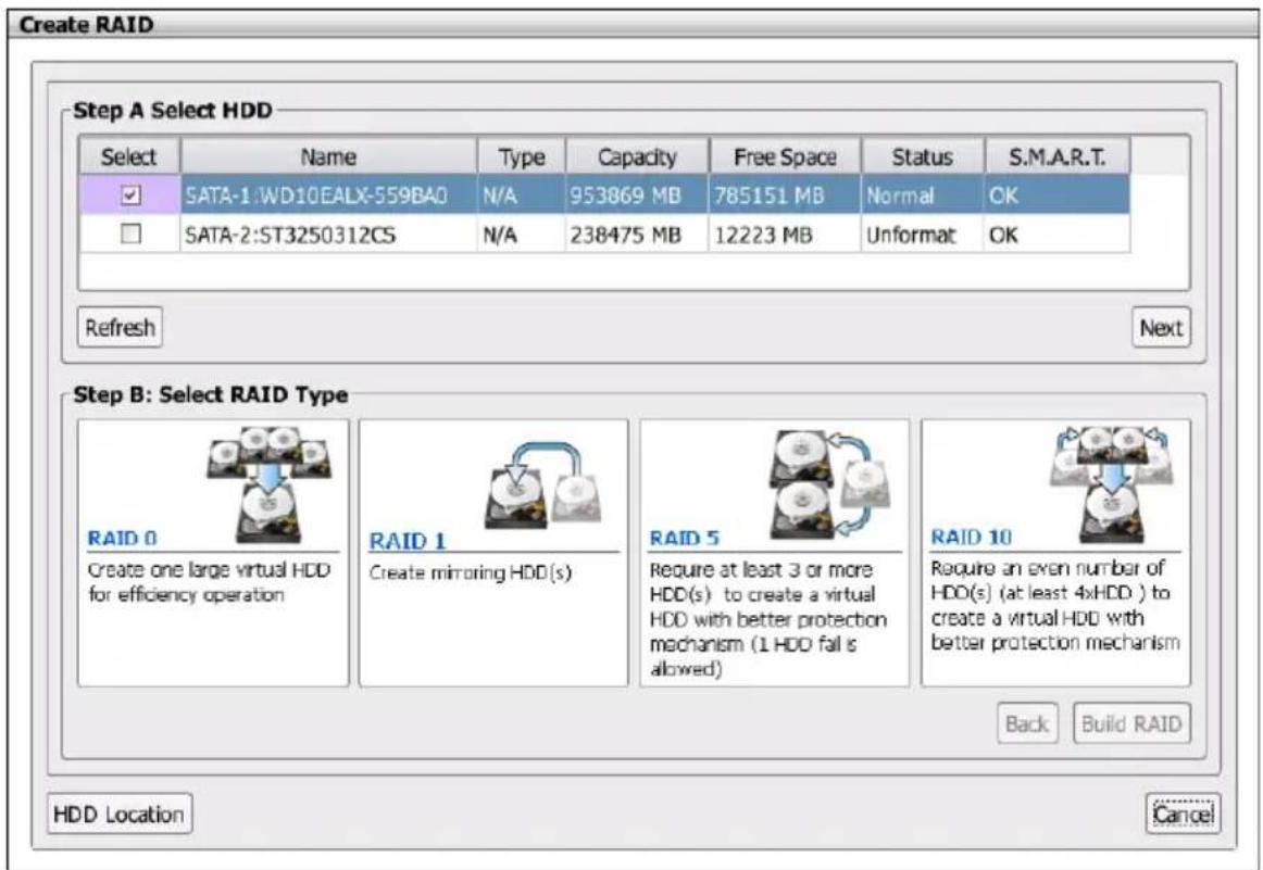
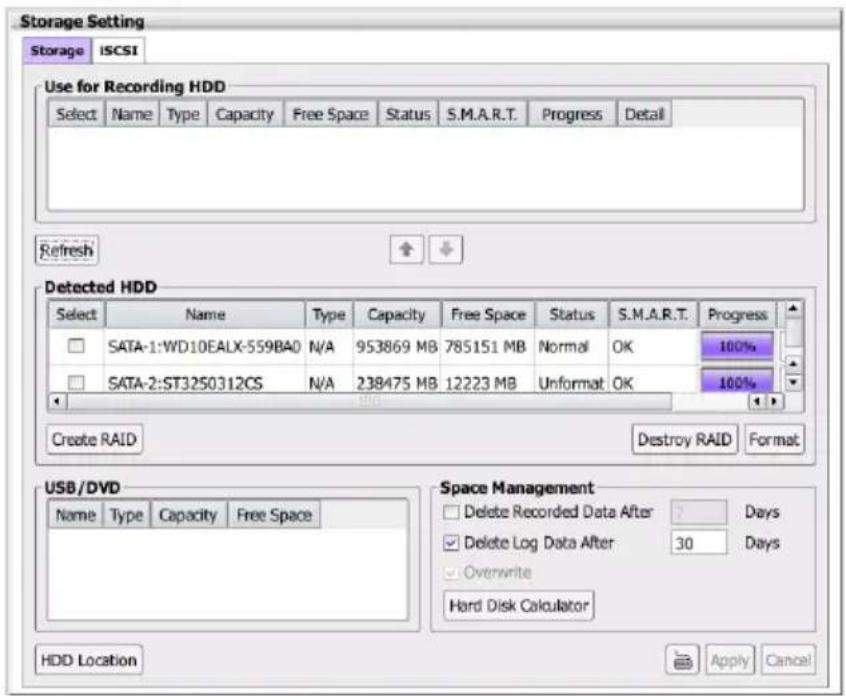
Follow the below steps to build an RAID storage.
- In Storage Setting page, click Create RAID button.
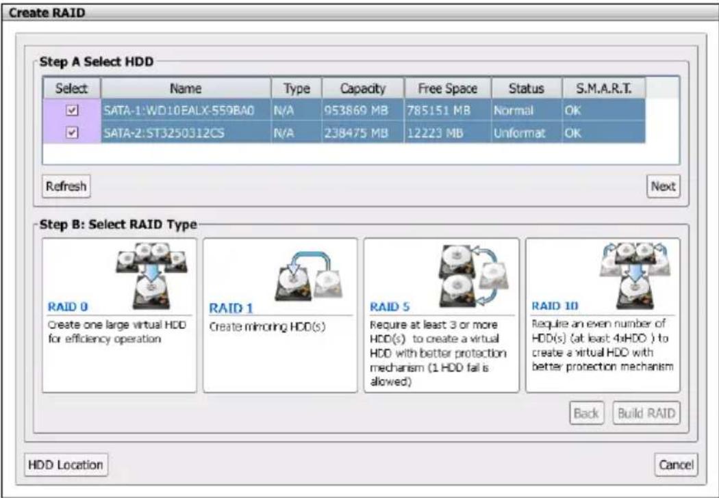
- In Create RAID page, select hard disks (Step A) and click Next button to go to Step B.
- Then, select the RAID type (Step B). There are some rules for each RAID type; therefore read the description of each RAID type before choosing.
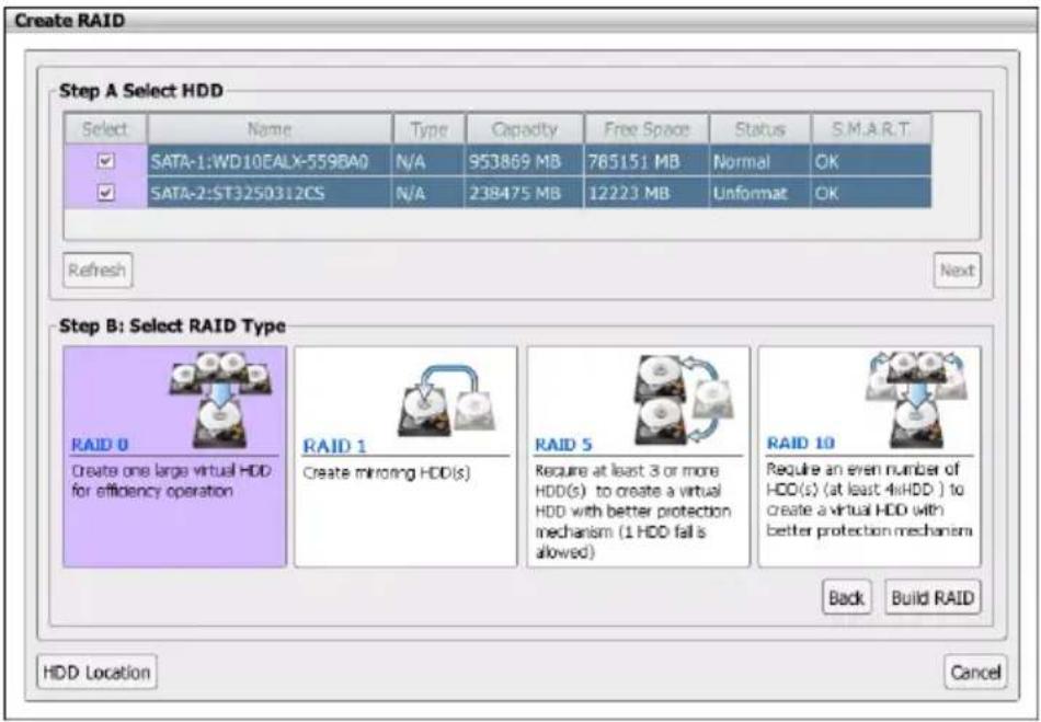
- Click Build RAID button to start RAID creating process. To re-choose the hard disk or RAID type, click Back button. Click Cancel button to exit Create RAID page.
- Next, click Yes to confirm the process.
- When RAID storage is built, click OK to complete the process.
- When the RAID is created, you should see the RAID drive in Detected HDD section.
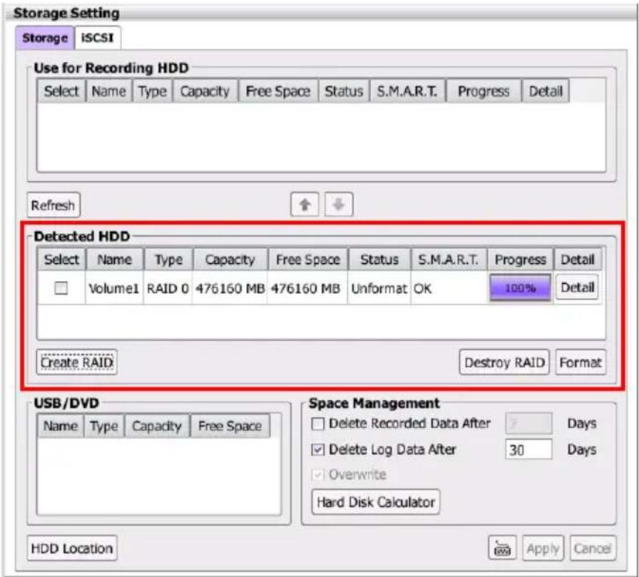
- Click Detail button of RAID drive, it displays the hard disks location of RAID on NVR/DVR unit and related information.
[Not]
When the word "STAT#" is display in red text, it means HDD status is un-normal.
When HDD status is shown as "N/A"; it means HDD status is normal and the word "SATA#" is display in white text.
-
The RAID drive needs to format before using it as a storage path. Select the RAID drive and click Format button.
-
After formatting, the RAID drive can be set as a storage path.
2.7.3 Setup Storage Path for Recording Data

- Without storage path, the NVR/DVR system won't be able to record.
- After storage path is added, the system will star to record.
Add a storage path for saving recording video data.
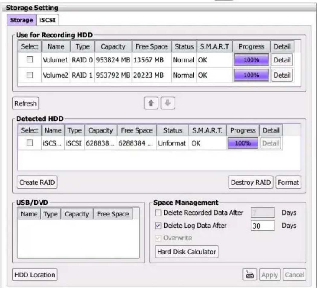
- In Storage Setting page, click Storage tab. Select hard disk, RAID drive, or iSCSI HDD and click button.
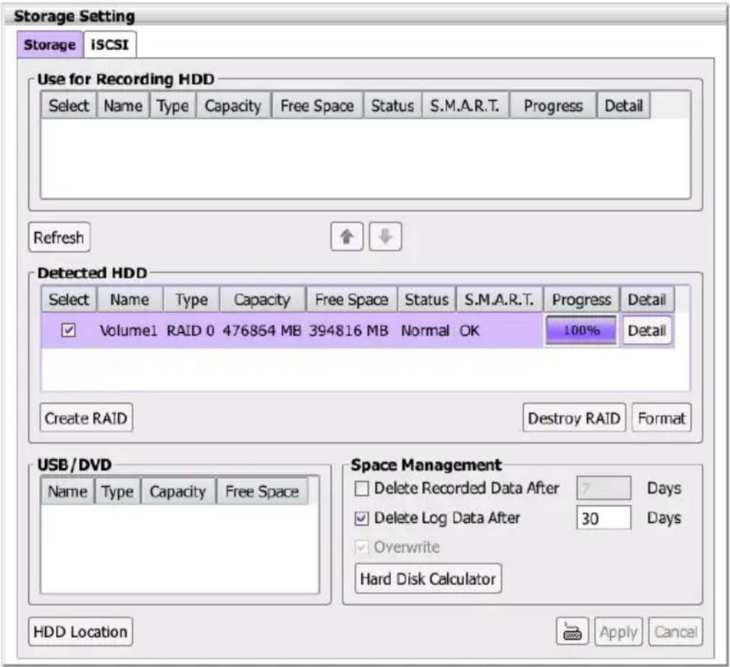
- The selected hard disk, RAID drive, or iSCSI HDD will be added into Use for Recording HDD section.
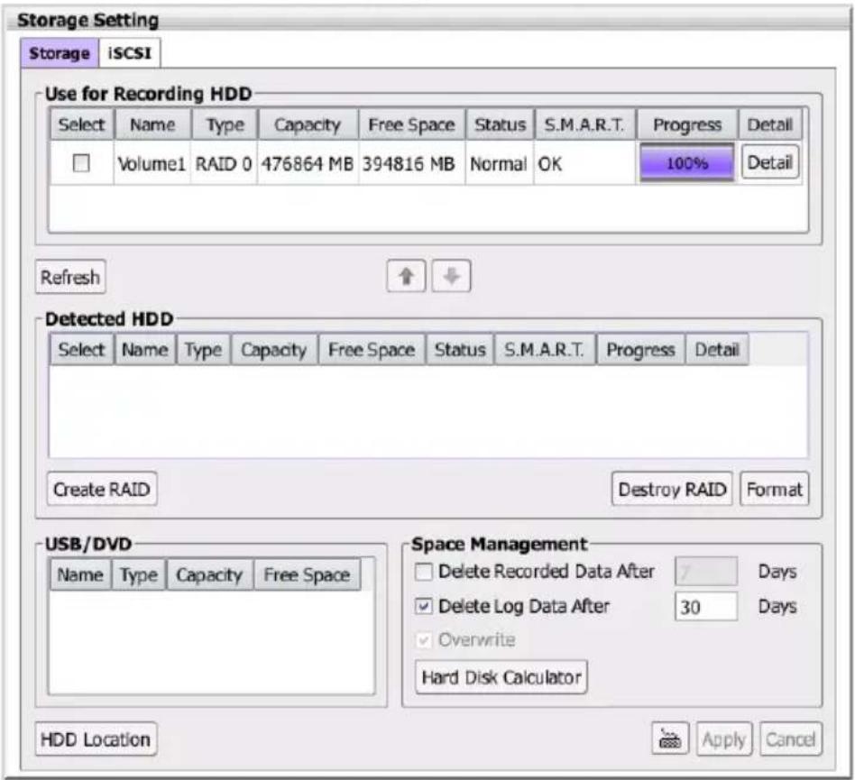
- To remove the hard disk or RAID drive, select hard disk, RAID drive, or iSCSI HDD in Use for Recording HDD section and click button.
2.7.4 Setup Hard Disk and Event Log Recycle Time
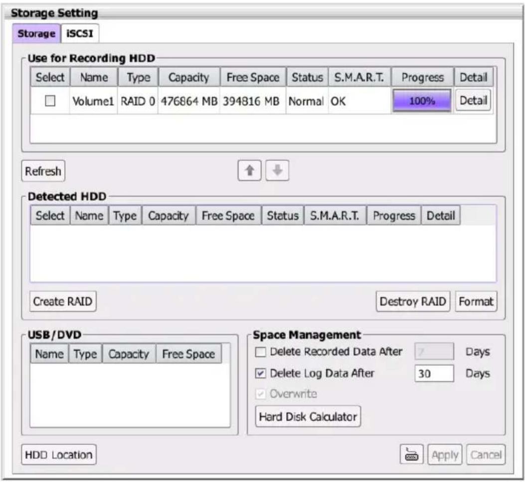
■ Delete Recorded Data After Days: If user wants the system to automatically erase the data after a certain days, enable the Delete Recorded Data After check box and enter the numbers of days in Days text box.
■ Delete Log Data After Days: If you want the system to automatically erase the logs after a certain days, enable the Delete Log Data After check box and enter the numbers of days in Days text box.
■ Overwrite: When there is not enough free space to record one hour data, the system automatically replaces the oldest data. The default is enabled and cannot be changed.
2.7.5 iSCSI Setting
Connect the iSCSI server on your network to use as a storage path for saving recorded data.
- Enter the following information to connect the iSCSI server on your network.
■ Initiate Name: The initiate name of iSCSI server. User can find out on iSCSI server.
■ IP Address: IP address of iSCSI server.
■ Port: The port is used to connect with iSCSI server.
■ User name: The user name that is used to login iSCSI server.
■ Password: The password that is used to login iSCSI server.
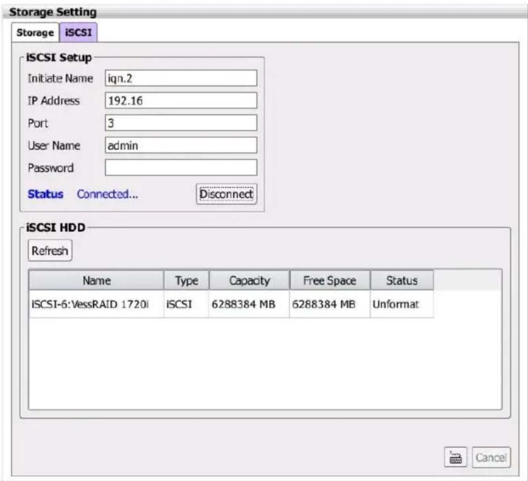
- Click Connect button to connect with iSCSI server.
-
When connection is successful, user should see the iSCSI HDD is list in iSCSI HDD section.
-
Click Storage tab, user will see the iSCSI HDD is listed in Detected HDD section.
- To format iSCSI HDD, select it and click Format button.
- To add iSCSI HDD as a storage path, select it and click button.
2.8 Camera Management
Connect and configure the camera channels. The total camera channels are up to 36.
Click Setup tab > Camera Setting.
Camera Management
| Camera List | ||||||||
| No. | Type | IP Address | Protocol | Model | Status | FPS | Bitrate | Detail |
| 1 | IP | Fail | 0 | 0 KB | Setting | |||
| 2 | IP | Fail | 0 | 0 KB | Setting | |||
| 3 | IP | Fail | 0 | 0 KB | Setting | |||
| 4 | IP | Fail | 0 | 0 KB | Setting | |||
| 5 | IP | Fail | 0 | 0 KB | Setting | |||
| 6 | IP | Fail | 0 | 0 KB | Setting | |||
| 7 | IP | Fail | 0 | 0 KB | Setting | |||
| Capacity | ||
| Used(MP) | Available(MP) | |
| All CHs | 0.00 | / 33.18 |
| Search List | ||||
| Search | Active IP | |||
| No. | / | IP Address | Port | P |
| Camera Information | |
| Name | |
| IP Address | |
| Port | 80 |
| Protocol | Aver |
| Model | FB2027-1 |
| Video Channel | |
| User Name | |
| Password | |
| Add to Camera | 01 |
natural_image
Close-up of a mechanical device with a circular symbol below it, no visible text or labels2.8.1 Connect the Analog Camera
- Connect the DVI cable to the video in port of NVR/DVR.
- Connect the analog camera to the DVI cable of NVR/DVR and power on the analog camera.
- In Camera List, select the channel that connect with Analog camera and select Type of camera as Analog.
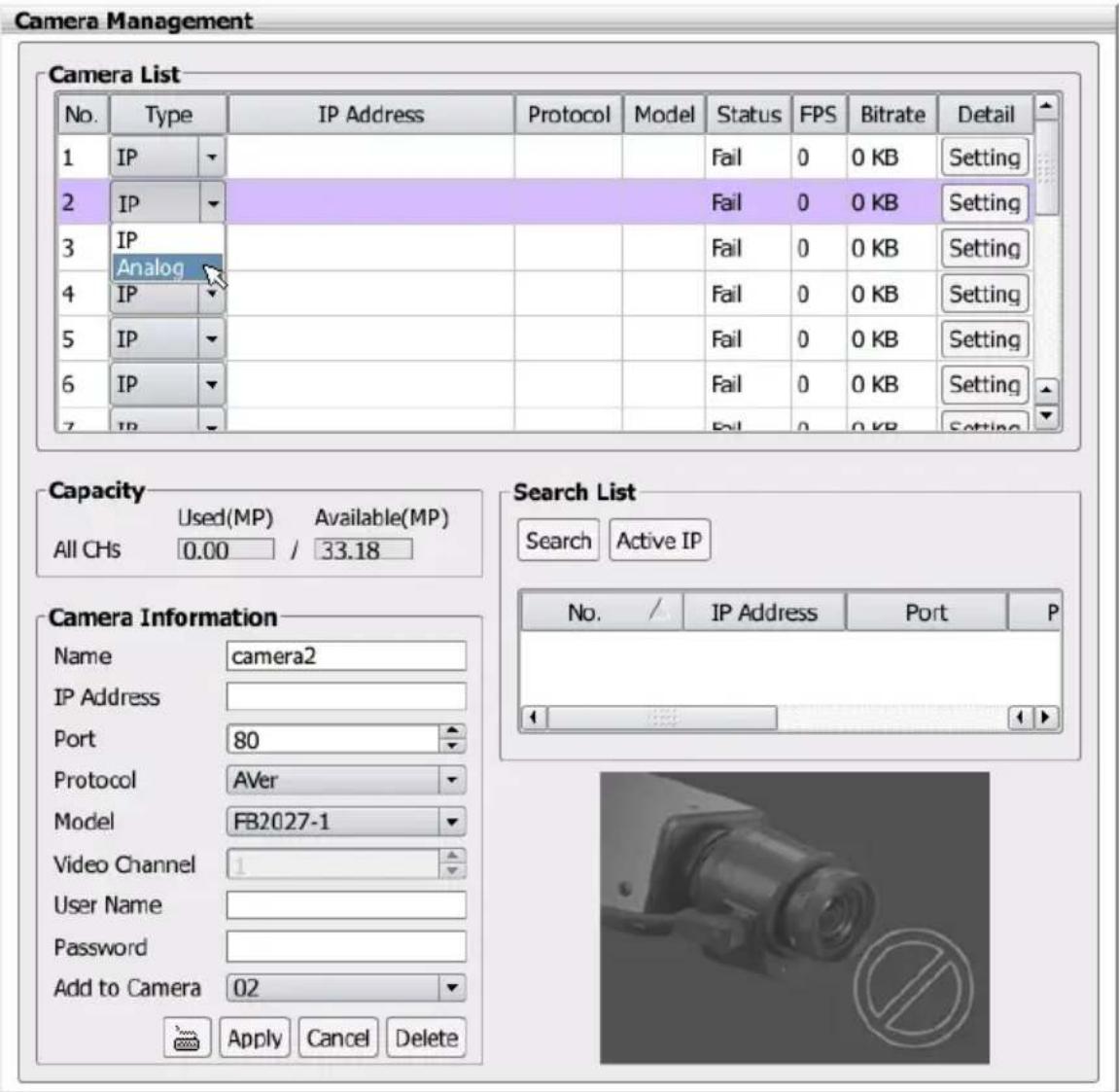
- Next, click Apply to make the connection. After connection is successful, user should see the live video of analog camera.
- To setup detail of analog camera, refer to Chapter 2.8.3.
2.8.2 Connect the IP Camera
- Click Setup tab > Camera Setting.
-
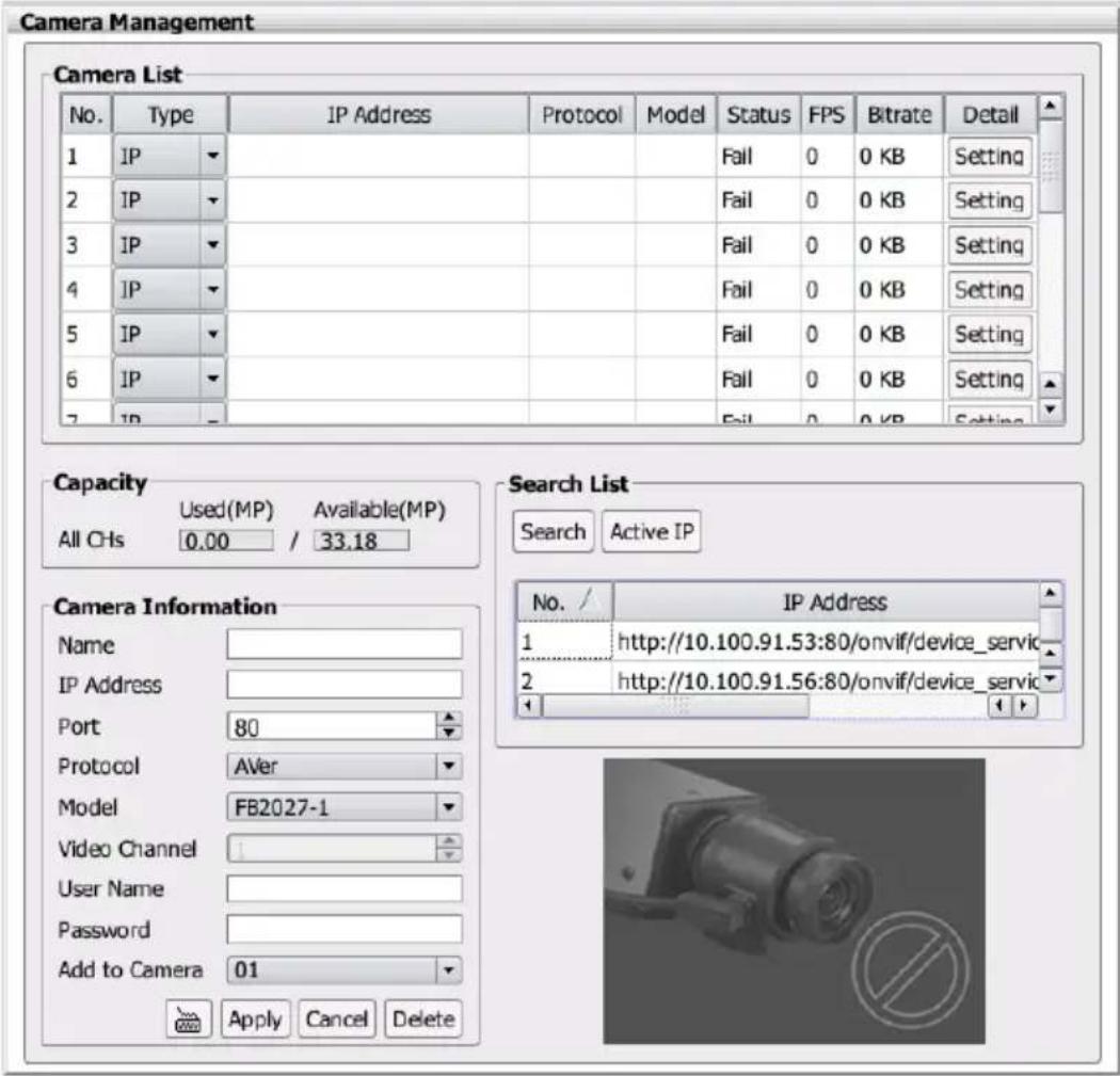
In Camera Information page is divided into 4 areas –Camera List, Capacity, Serach List, and Camera Information.
-
Camera List: Lists all camera channels. When the channel has connected IP camera, it displays the IP Address, Protocol, Model, connection Status, FPS, Bitrate, and configure detail button of the connected IP camera.
- Capacity: Displays the all connected IP cameras' resolutions in Used (MP) column and remain resolutions are displayed in Available (MP) column.
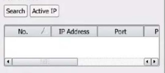
- Search List: To perform the auto search IP camera on your LAN network and list search result. Also, the NVR/DVR system provides Active IP function for user to configure AVer IP cameras series from NVR/DVR site (see also Chapter 2.8.2.1).
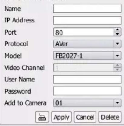
- Camera Information: For entering the IP camera's parameters when connects the IP camera.
Camera Management
| Camera List | |||||||||
| No. | Type | IP Address | Protocol | Model | Status | FPS | Bitrate | Detail | |
| 1 | IP | Fail | 0 | 0 KB | Setting | ||||
| 2 | IP | Fail | 0 | 0 KB | Setting | ||||
| 3 | IP | Fail | 0 | 0 KB | Setting | ||||
| 4 | IP | Fail | 0 | 0 KB | Setting | ||||
| 5 | IP | Fail | 0 | 0 KB | Setting | ||||
| 6 | IP | Fail | 0 | 0 KB | Setting | ||||
| 7 | IP | Fail | 0 | 0 KB | Setting | ||||
Capacity

Search List
Camera Information
natural_image
Close-up of a mechanical component with a circular symbol (no readable text or labels)- Click Search button to find IP cameras on LAN network.
- In Search result list, select the IP camera that user wants to connect. Then, select the IP camera channel that user wants to connect the selected IP camera. Enter the User name and Password of IP camera if the connection authentication is required.
- Click Apply button to make a connection.
- After connection is successful, user should see the live video is displayed.
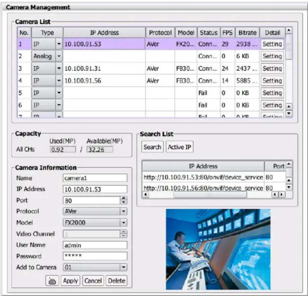
- Also, user can enter the following data in Camera Information section and click Apply button to make a connection of the IP camera.
■ Name: Give a name for the IP camera.
■ IP Address: Enter the IP camera's IP address.
■ Port: Enter the port of connecting IP camera.
■ Protocol: Enter the brand name of the IP camera. For example: AVer, AXIS...etc.
■ Model: Enter the model type of the IP camera. For example: SF2012H-B
■ User Name: The user name of IP camera for authentication when connect to the IP camera.
■ Password: The password of IP camera for authentication when connect to the IP camera.
■ Add to Camera: The channel that is going to connect the IP camera.
-
To configure the IP camera's detail setting, please refer to Chapter 2.8.3.
-
To connect another IP camera, repeat the above steps.
2.8.2.1 Use Active IP Function
The Active IP function allows user to configure the AVer IP camera series' IP mode, IP address, subnet mask, gateway, port, login ID, and password on NVR/DVR system.

The Active IP function supports AVer IP camera series only.
- In Camera Information dialog box, click Search button. Then, select the IP camera that is in red text from Search List.
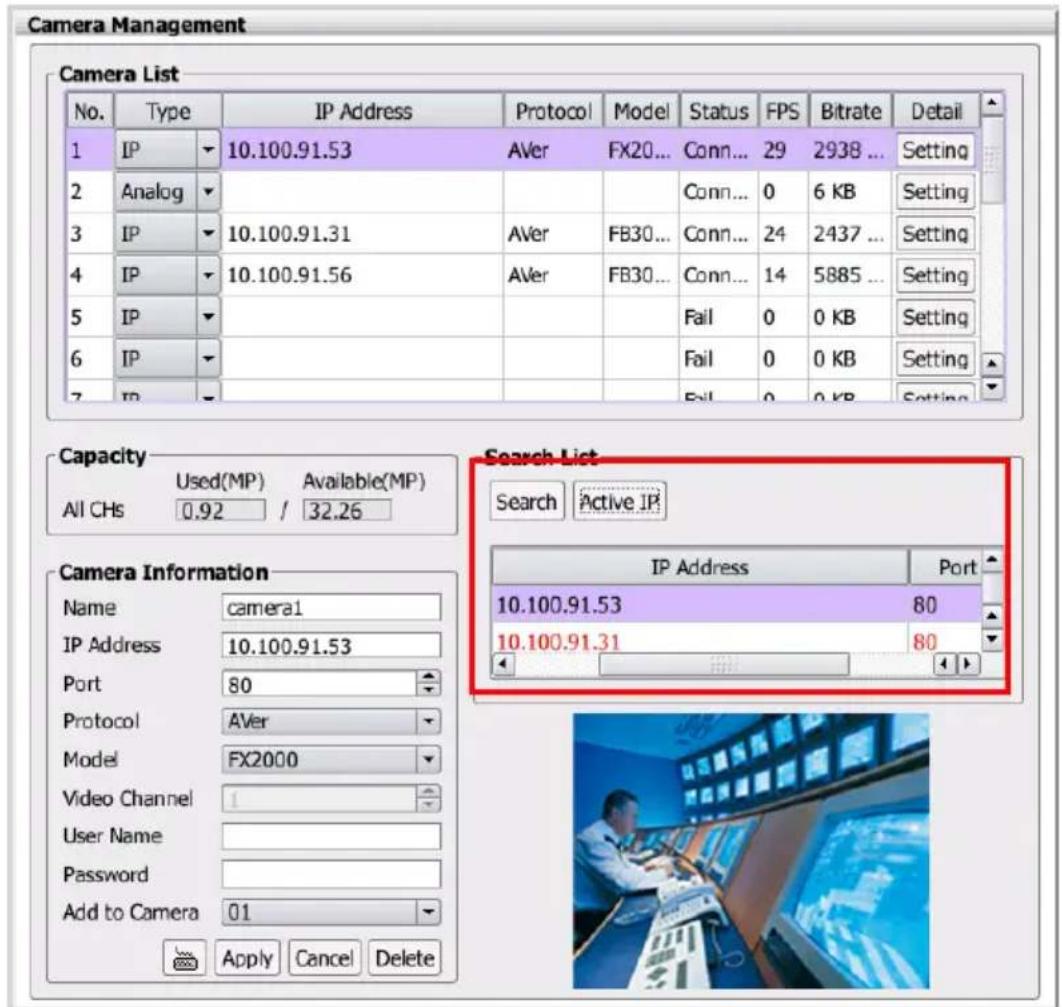
-
Click Active IP button and Active IP dialog box is appeared.
-
In Active IP dialog box, user can change IP mode of the IP camera and configure related parameters.
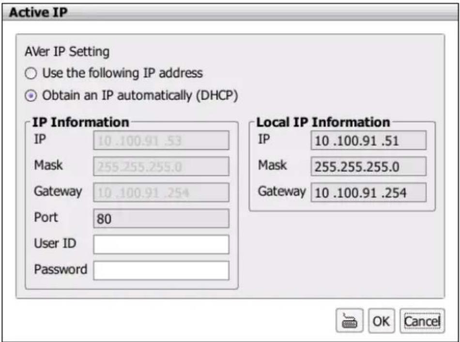
- After configuring, click OK to save the setting.
2.8.3 Camera Detail Configuration
User can configure the IP camera's stream settings and related parameters.
Click Setup tab > Camera Setting; click + to expand list of Camera Setting and click the Camera number that user wants to configure. Or, click Setting button of IP camera in Camera Management dialog box.

The camera functions are depended on IP/analog camera has supported. The un-available functions are is gray out.
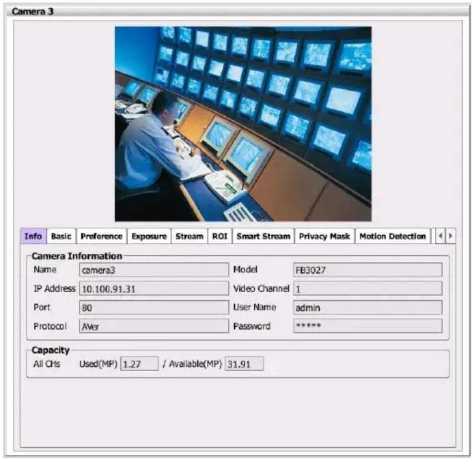
■ Info
Display the name, IP, port, protocol, model, channel, Login ID, password, and resolution of IP camera.
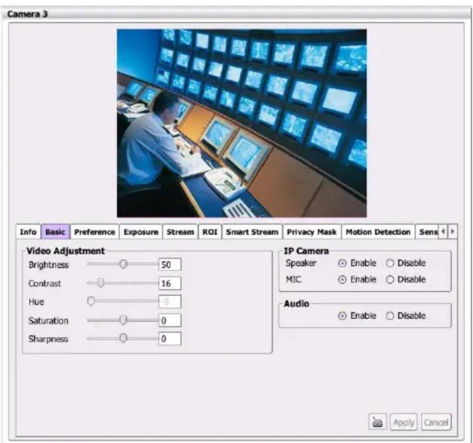
■ Basic
✿ Video Adjustment: Configure the Brightness, Contract, Hue, Saturation, and Sharpness of IP camera.
IP Camera: Enable/disable Speaker and MIC of IP camera.
Audio: Enable/disable audio function of IP camera.
■ Preference
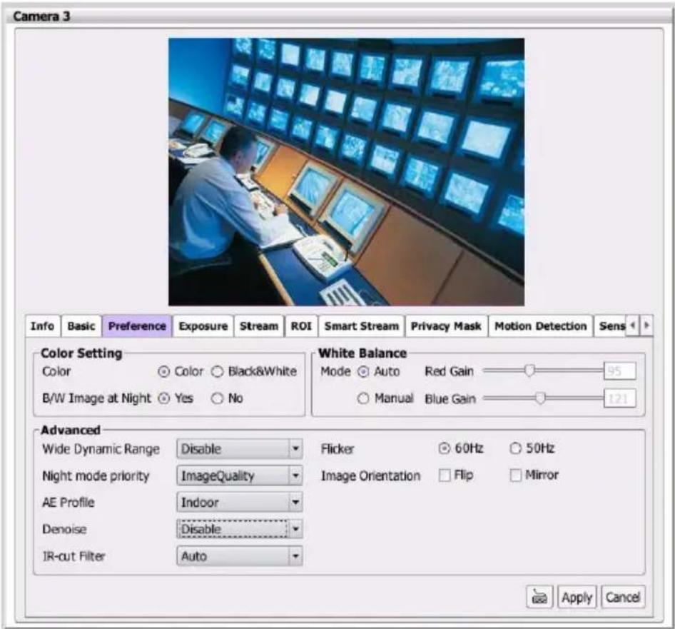
In Preference page, user can tune the IP camera white balance, select display color or black & white, set the flicker frequency, change the video orientation, and adjust the some advance settings. After completing the setting, click Apply to save the setting and Cancel to keep the old setting.

The Preference setting only support for IP camera.
Color Setting
- Color: Select the Color or Black&White mode.
- B/W Image at Night: Enable/disable to switch to B/W during night mode.
White Balance: Adjust white balance in auto or manual mode.
Advanced
- Wide Dynamic Range: WDR effectively balances the video image on the screen in both bright and dark areas to make it possible to see clear details. There are 3 levels for your choice or disable WDR.
- Night mode priority: Select the one you want to prioritize during night mode image quality or frame rate.
- Denoise: Select Disable/2D/3D/Auto to reduce the excessive noise on the video image. Select Auto and set the Sensitivity level.

- AE Profile (Auto Exposure Profile): Select the auto exposure scenes – Indoor, Outdoor, or ManualIRIS.
- IR-cut Filter: The IR cut filter is a mechanism that prevents the infrared light from hitting the sensor. During day time the IR light has an interfering effect on the image quality of the camera, which leads to corruption of color and contrast as well as blurring. At night time, the infrared light is used to achieve more detailed images in the dark or with low ambient light.
Auto: automatically switch on/off the IR cut filter. It uses the light sensor in front of the camera to determine the level of ambient light.
Day Mode: switch on the IR cut filter at all time to prevent the IR light from hitting the sensor so that the color will not be corrupted.
Night Mode: switch off the IR cut filter at all time to let the sensor receives the IR light which could help improve low light sensitivity.
✿ Schedule: specify the time on when to switch off the IR cut filter to night mode. The time format is hh:mm and in 24-hour clock time.

- Flicker: Select the flicker frequency.
– Image Orientation: To Flip or Mirror the video on screen.
■ Exposure
In Exposure page, user can set the exposure area, exposure mode, and calibrate the DC Iris. After completing the setting, click Apply to save the setting and Cancel to keep the old setting.

The Exposure setting only support for IP camera.
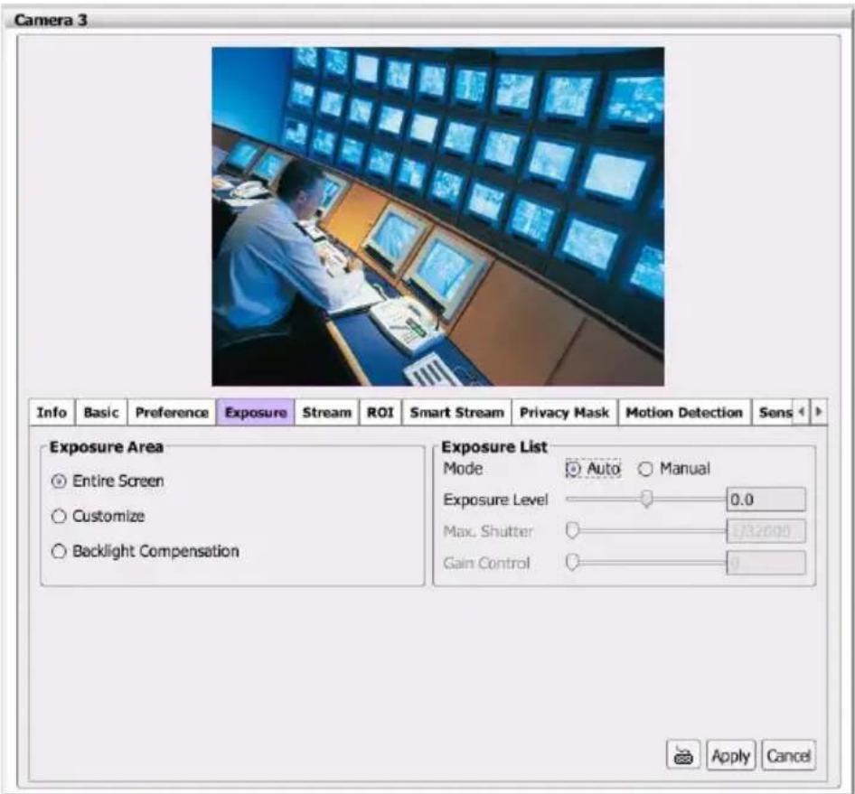
Exposure Area: Select the exposure area to define the light distribution and bring out more details.
- Entire screen: measure the entire screen to adjust the exposure.
- Customize: measure the exposure to where the adjustable and movable frame on the screen is located. Move the spot to dark zone to adjust the light condition.
- Backlight compensation: measure the exposure at the center of the screen.
Exposure List: Select to Auto or Manual adjust the exposure.
- Auto: adjust exposure level from -2.0 to +2.0.
- Manual: adjust max shutter and gain control.
Stream
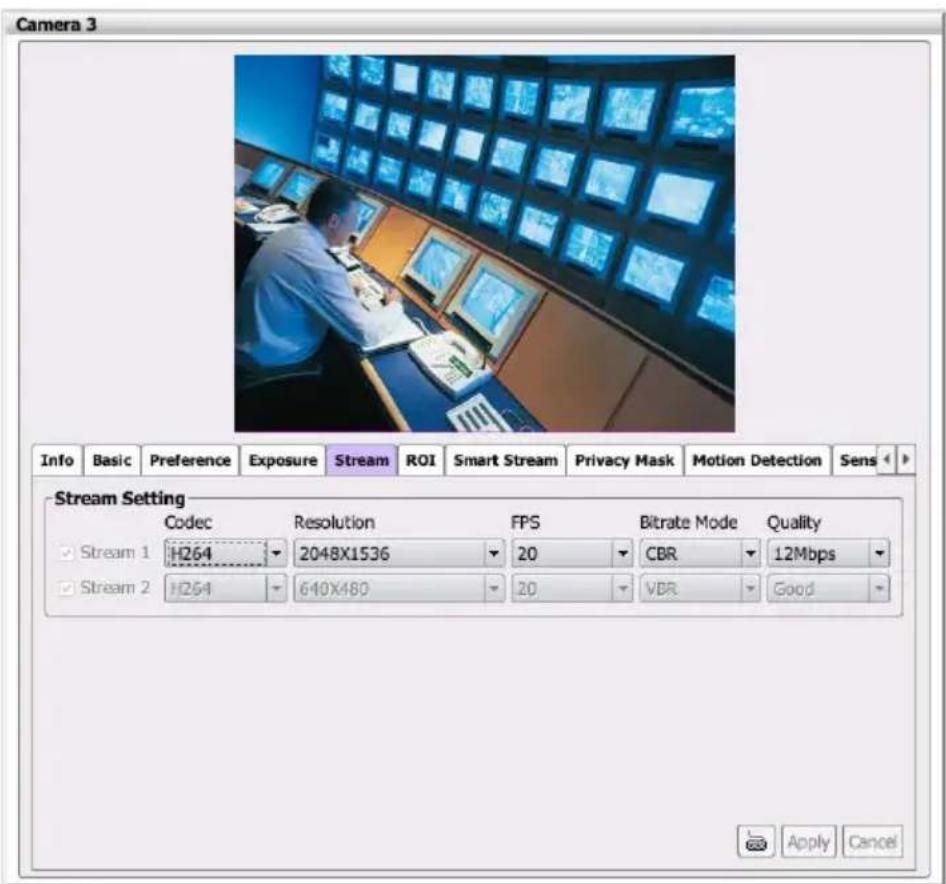
User can setup Codec, Resolution, FPS, Bitrate Mode, and Quality of Stream 1 on the IP camera channel. The Stream 1 is enabled in default. After completing the setting, click Apply to save the setting and Cancel to keep the old setting.

The NVR/DVR system doesn't support for stream 2 setting.
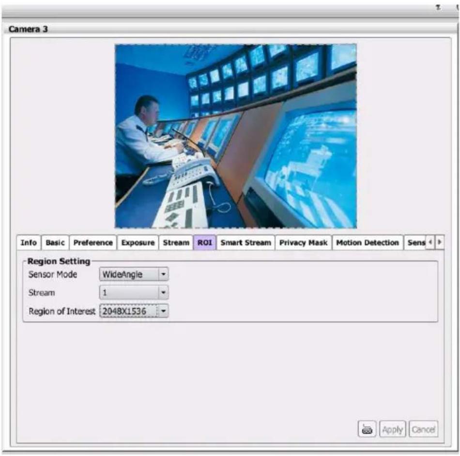
ROI
ROI stands for Region on Interest. It helps users to optimize bandwidth and storage. Users can select 1 or 2 key area(s) to transmit as separate streams for targeted preview and recording.

The ROI setting only support for IP camera.
- Select the Sensor Mode and Stream.
- Then, select the Region of Interest from drop-down list and a gray frame will show up. The gray frame size is depended on the Region of Interest that user has selected. Click on the frame and move it to the region that user wants to select.
- After completing the setting, click Apply to save the setting and Cancel to keep the old setting.
■ Smart Stream
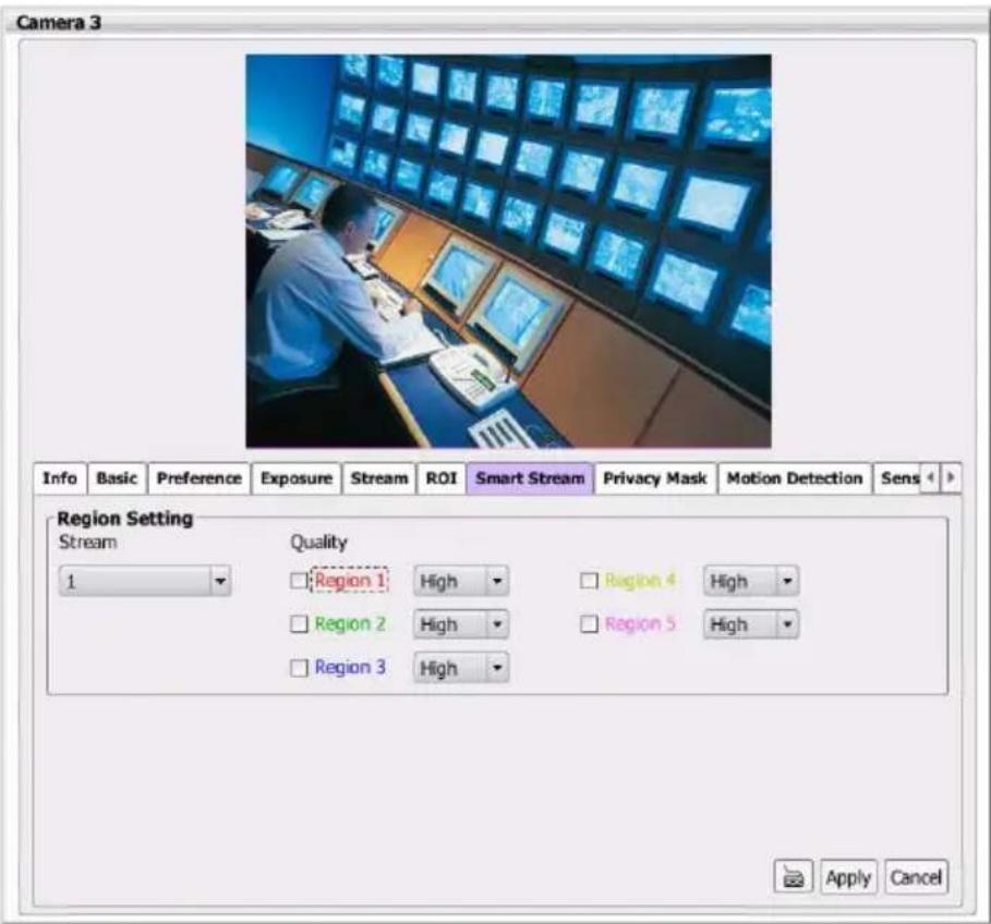
Smart Stream optimizes bandwidth and storage space by increasing or decreasing quality for selected areas based upon criticality. Users can define up to 5 areas per stream to ensure sharp images for crucial areas, while saving bandwidth on non-essential areas. Typical applications include entrances, access gates, production lines, art galleries and museums.
After completing the setting, click Apply to save the setting and Cancel to keep the old setting.

The Smart stream setting only support for IP camera.
Stream: Select the streaming source. This option is only applied to H.264.
Quality: Select the Region 1/2/3/4/5 and set the high/low. Each region frame is corresponded to the color of text, ex: Region 1 is red frame. Drag the frame to select the area on screen.
– High: video quality of selected area is better than that of un-selected area.
- Low: video quality of selected area is worse than that of un-selected area
■ Privacy Mask
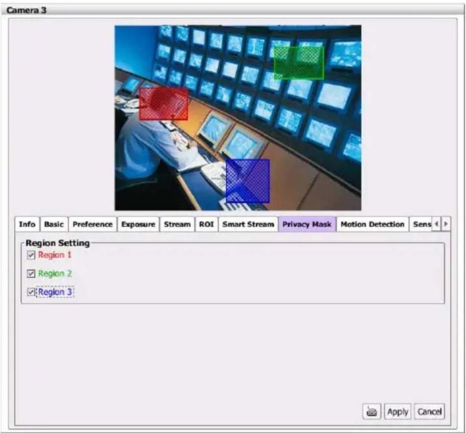
In Privacy Mask page, user can enable 3 privacy masks. Simply adjust the size and position the mask on the area user wants to conceal. The viewer will not be able to see the masked area. It will cover the video screen with black frame. After completing the setting, click Apply to save the setting and Cancel to keep the old setting.
■ Motion Detection
In the motion detection page, the frame will blink when the motion detected has reached the percentage threshold setting. This feature can be utilized to trigger a response in Event setting.
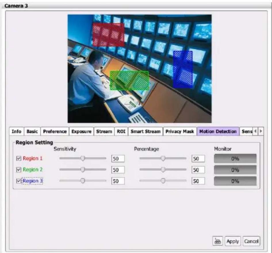
- Enable the region check box (Region 1, Region 2, Region 3) to create a motion detection frame.
- Move and adjust the frame to the area you want to detect the motion.
- Adjust the sensitivity and percentage. Sensitivity detects the motion on the screen and assesses the changes in pixel thru percentage. The motion detection will activate when the Monitor level reaches the defined percentage.
- After completing the setting, click Apply to save the setting and Cancel to keep the old setting.
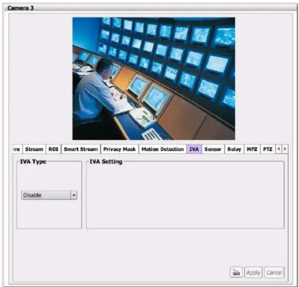
■ IVA
Form drop-down list select the IVA function – Cross detection, Tampering, Missing object, or Suspicious object.
Cross Detection
Cross detection function detects moving objects that cross the virtual lines that user has set up in IP camera application and to trigger the alarm.
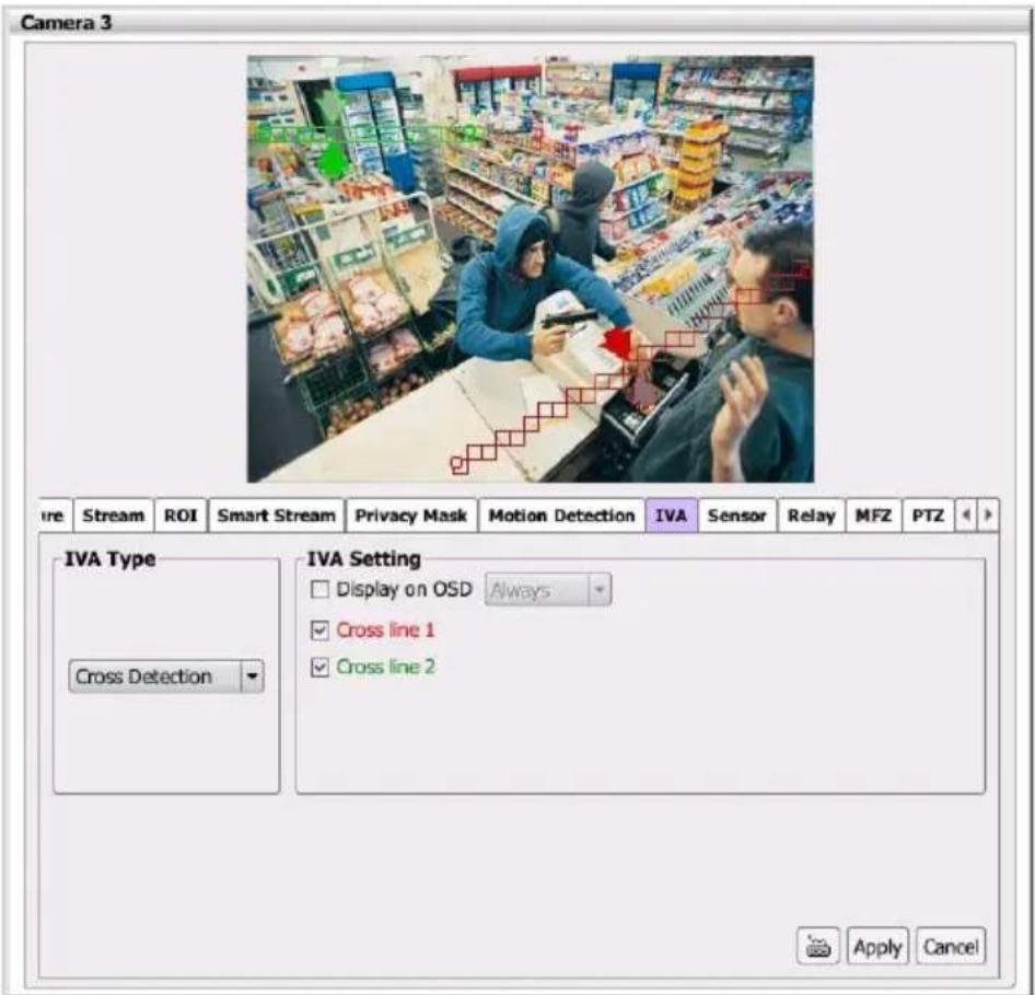
-
Enable Cross line 1/2 check box
-
You will see the red/green line is shown on the video screen.
-
Drag the red line or green line to set the area for cross detection. You can set both lines for cross detection or one of the lines. There is no priority for these 2 lines; the color is just for you to differentiate when both lines are set.
-
After setting the cross detection area, click the arrow of line to set cross detect direction. The arrow point is the direction of cross way.
-
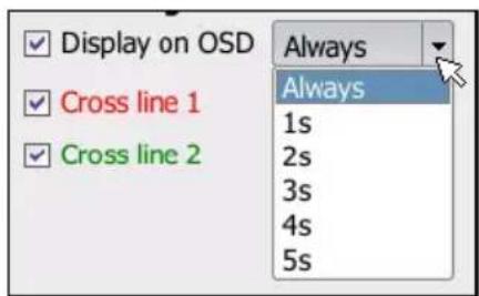
In Display on OSD, if user wants to see the cross detection line(s) always display on the screen, select always. If user only wants to see the cross detection line(s) when the cross detection has triggered, select the time period (1s, 2s, 3s, 4s, or 5s) for cross line displaying on screen.
-
Click Apply to save the settings.
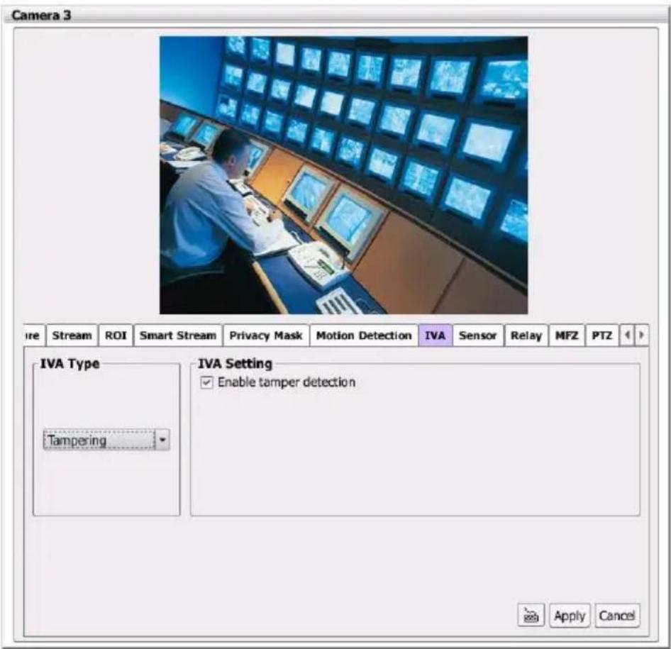
Tampering
Select Enable tamper detection to enable tampering function. And, alarm will trigger when the following situation has occurred.
- Spray-painting: Alarm is triggered when the camera has detected the painting sprayed on the camera's view for over 2 seconds.
Intention Block /Cover: Alarm is triggered when the camera has detected the camera's view being blocked intentionally over 2 seconds.
■ Accidental redirection: Alarm is triggered when someone re-directs the position or direction of camera accidentally.
■ Defocusing: Alarm is triggered when the camera has lost focus.
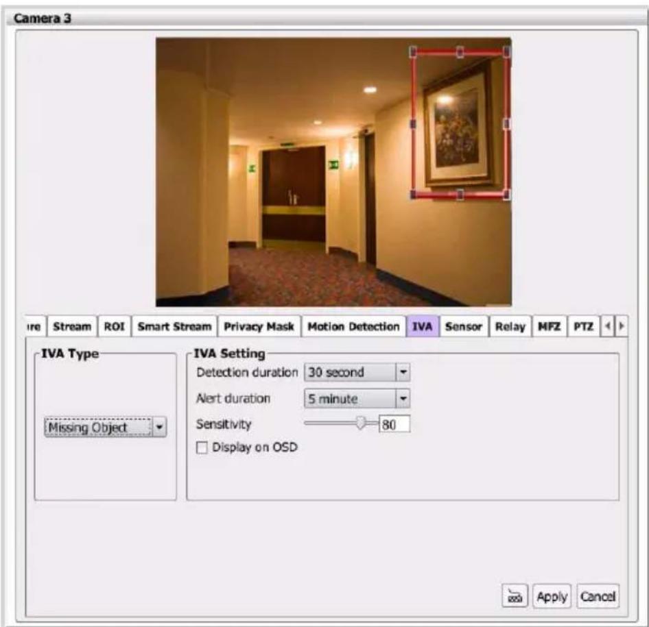
Missing Object
Select a certain object on the screen for the camera system to detect; System gives alarm when the object disappears.
- Select the Missing Object from the drop-down list.
- A red frame will show up on the screen. Click and drag the red frame to the object position and click the frame to adjust the size of frame.
- Detection Duration: Set the lasting time for camera system to detect the object.
- Alert Duration: Set the alarm lasting time after alarm has been triggered.
- Sensitivity: Set the degree of response of detection.
- Display on OSD: Mark to enable the missing object frame to display on screen when missing object has triggered.
Suspicious Object
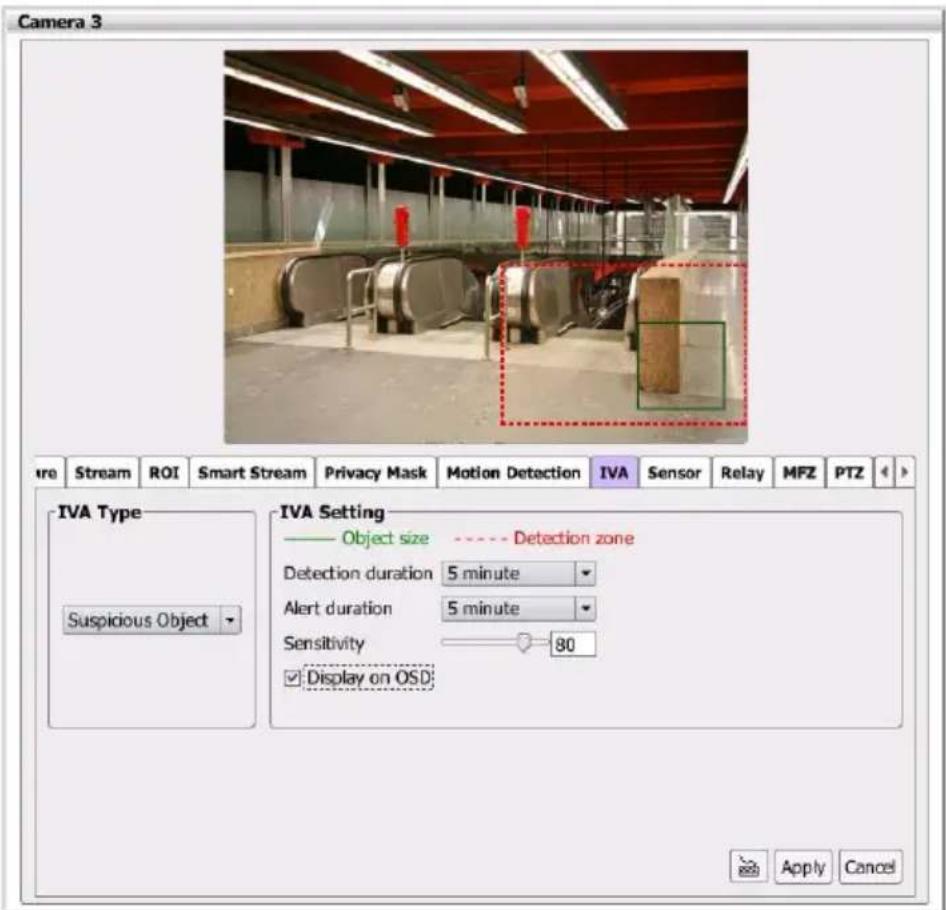
Suspicious Object is an unusual object appears on the screen.
- Select the Suspicious Object from the drop-down list.
-
A red frame and green frame will show up on the screen. The red frame is defined as detecting zone and green frame is defined as object size frame. Click and drag the red frame to the position and click the frame to adjust the size of frame. Next, click and drag the green frame the detecting zone and adjust the size of object for detection.
-
Sensitivity: Set the degree of response of detection.
-
Detection Duration: Set the lasting time for camera system to detect the object.
-
Alert Duration: Set the alarm lasting time after alarm has been triggered.
-
Display on OSD: Mark to enable the suspicious object frame to display on screen when suspicious object has triggered.
■ Sensor
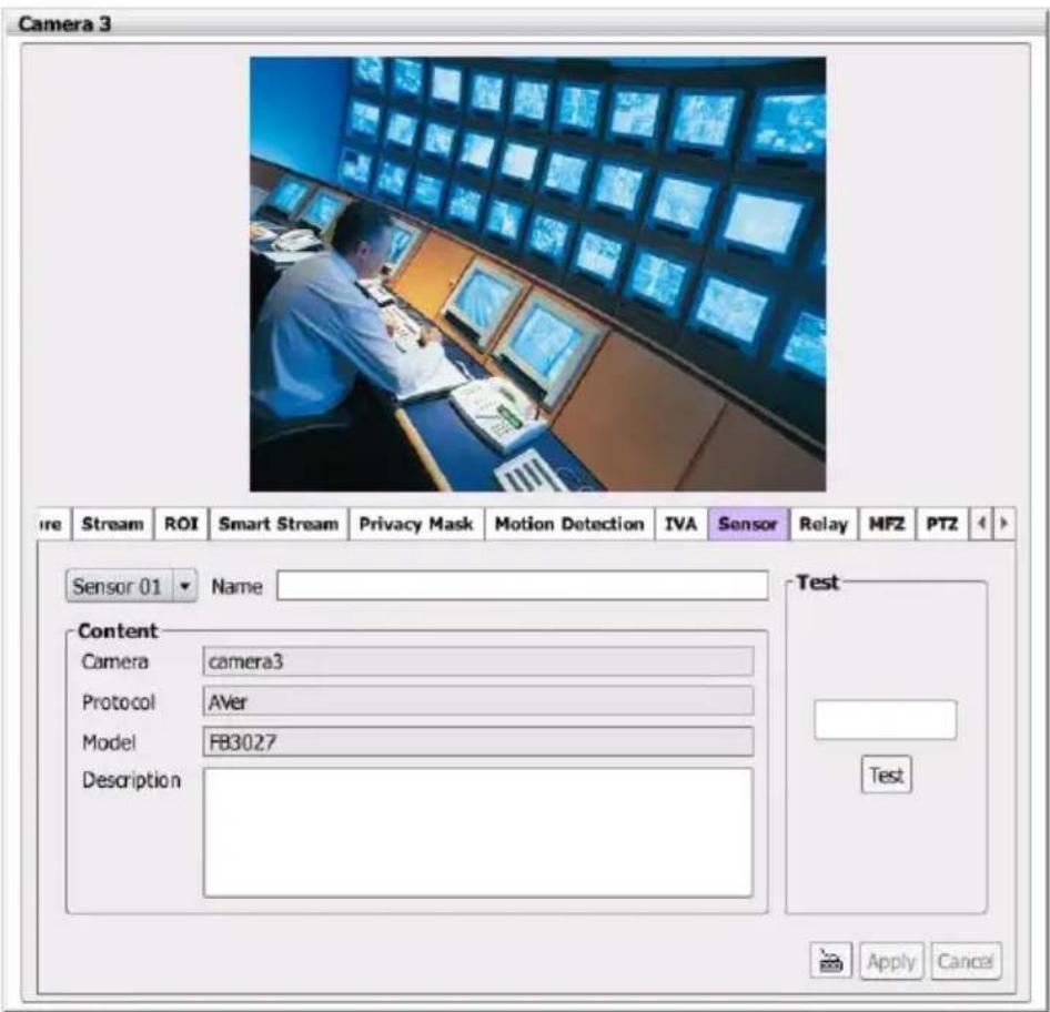
Setup the sensor of IP camera.
- In Camera Management dialog box, click Sensor tab.
- Click the drop-down list and select the sensor ID number.
- Enter sensor name in Name column
- In the Content section, display the NVR/DVR system automatically detects the camera and input relates information. Enter a short comment for this sensor in Description column.
- In the test section, click Test to check the sensor status. Red is high and Green is low.
- Click Apply to exit and accept the setting and Cancel to exit without saving the setting.

The Sensor setting only support for IP camera.
■ Relay
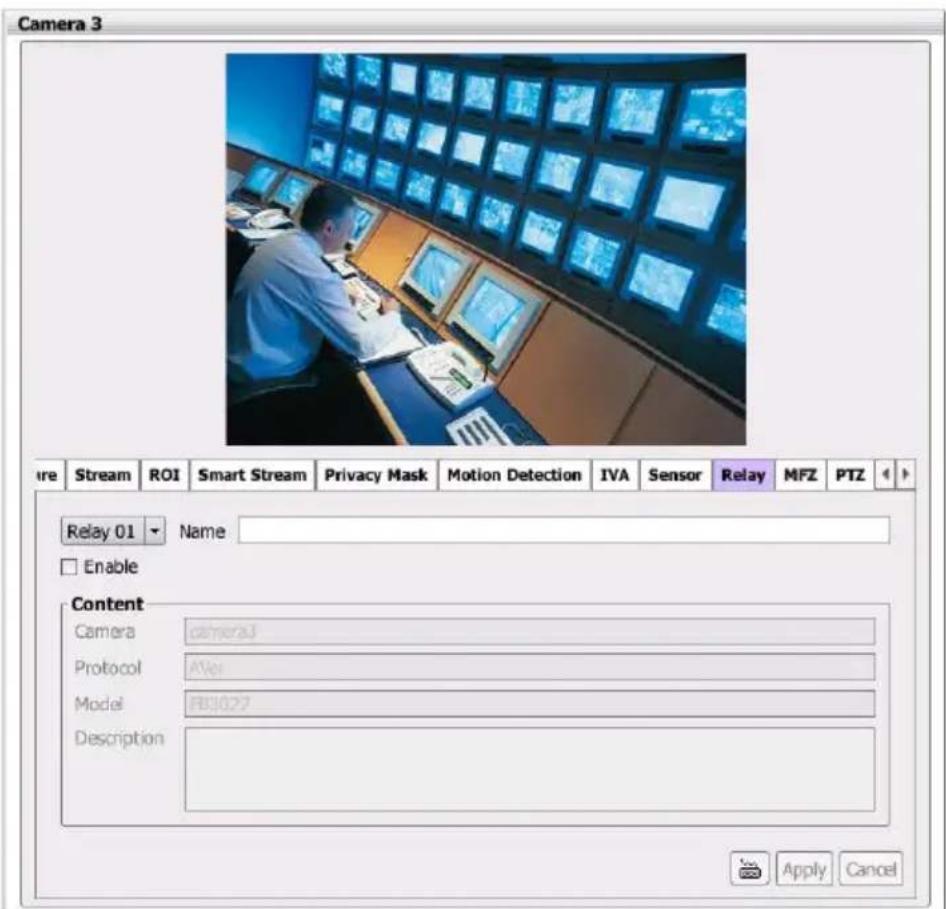
Setup the relay of IP camera.
a. In Camera Management dialog box, click Relay tab.
b. Click the drop-down list and select the relay ID number.
c. Enter relay name in Name column
d. In the Content section, display the system automatically detects the camera and input relates information. Enter a short comment for this relay in Description column.
e. Click OK to exit and accept the setting and Cancel to exit without saving the setting.

The Relay setting only support for IP camera.

The IP camera has motorized lens can perform MFZ function(motorized focus and zoom).
The MFZ setting only support for IP camera.
To adjust the focus or zoom in/out the view of IP camera.
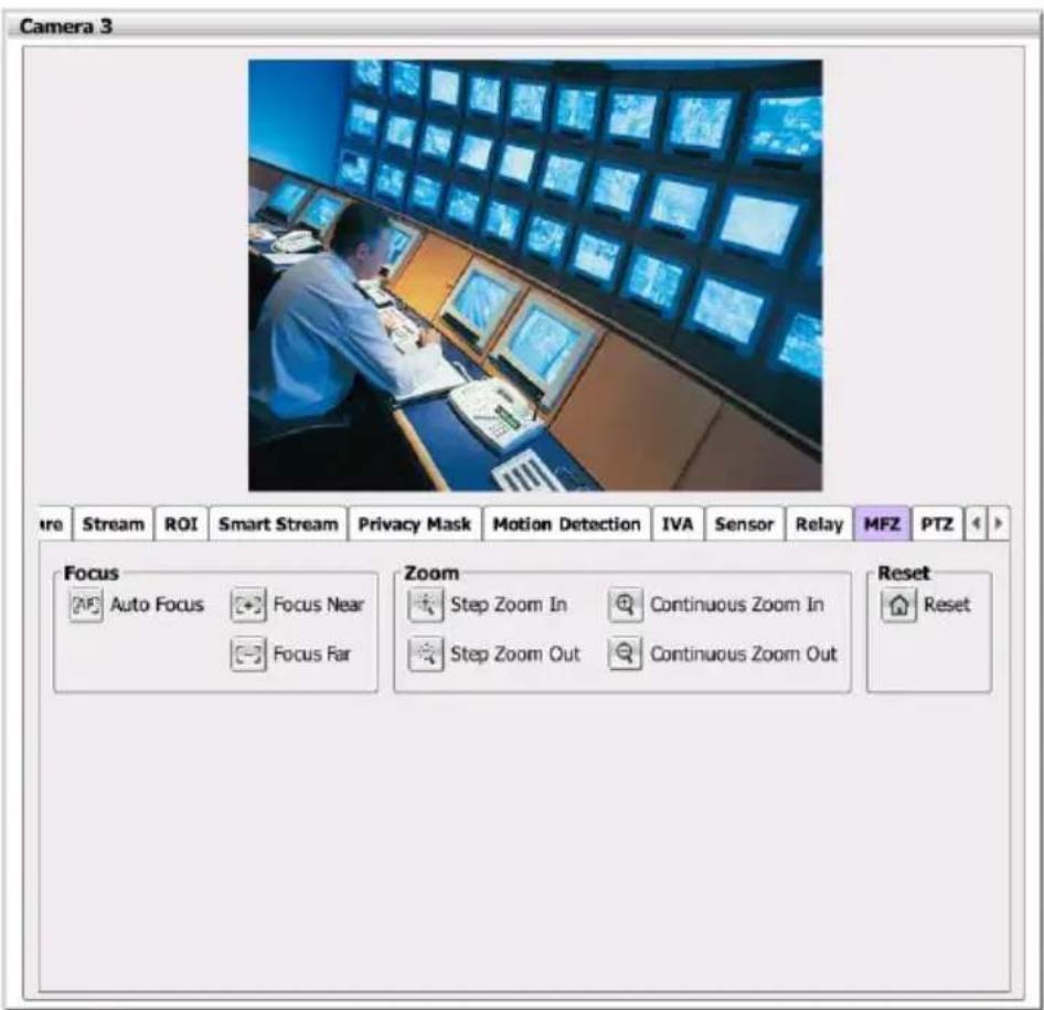
| Name | Function | |
 | Auto focus | Automatically focus on where focus cursor ( ) has pointed. |
 | Focus near | To adjust the near side of focus. |
 | Focus far | To adjust the far side of focus. |
 | Step zoom in | To zoom in one step by step for fine focus adjusting. |
 | Step zoom out | To zoom out one step by step for fine focus adjusting. |
 | Continuous zoom in | Press to zoom in continuous. |
 | Continuous zoom out | Press to zoom out continuous. |
 | Reset | To reset the zoom back to the center of screen view in default value (1x). |
■ PTZ Function
User can enable PTZ function if the IP camera has supported.
- In Camera Management dialog box, click Setup tab
- Then, select Camera # > PTZ tab.
- In PTZ setup page, click Use PTZ to enable PTZ function.
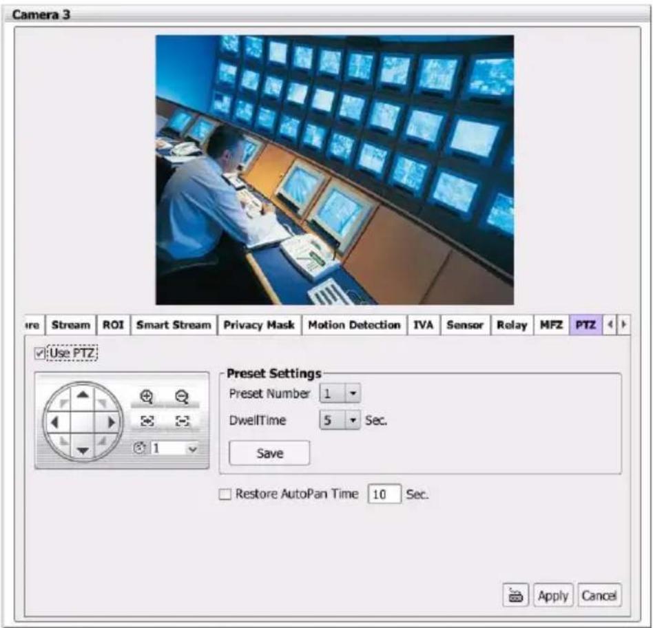
- Preset Setting: use the control panel to adjust the position of the camera and select the Preset Number to assign a number for the camera current position. After is done, click Save to keep the settings. Use these 2 buttons
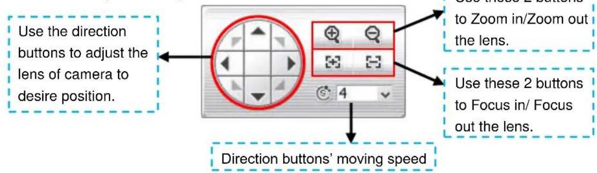
- DwellTime: for how long the camera stays in that position before it moves to the next one (the setup time period is 1\~60 seconds). After is done, click Save to keep the settings.
- Restore AutoPan Time: set a time period for restoring auto path function after the PTZ camera has been moved. Mark the check box and set the time period in second.
- Click Apply to save the settings.
- After completing the PTZ setting, user can operate the PTZ function through PTZ control panel in preview mode (see also Chapter 2.8.3).
2.8.3 Familiarizing Functions on PTZ Control Panel
User can control PTZ camera through PTZ control panel in preview mode. Enable and set up the PTZ camera; refer to PTZ Function.
- In preview mode, click (PTZ) icon to call out PTZ control Panel.
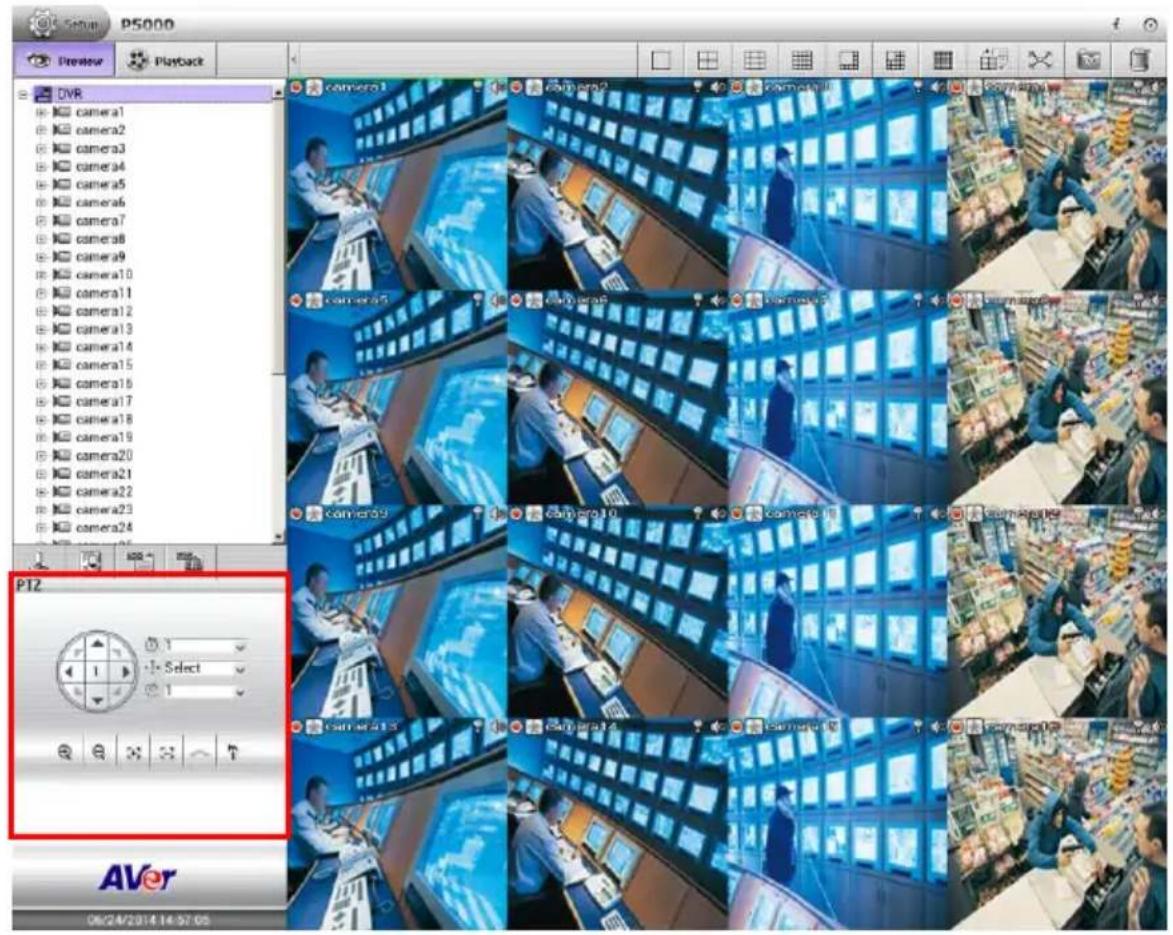
- The functions' description of PTZ control panel is as following.
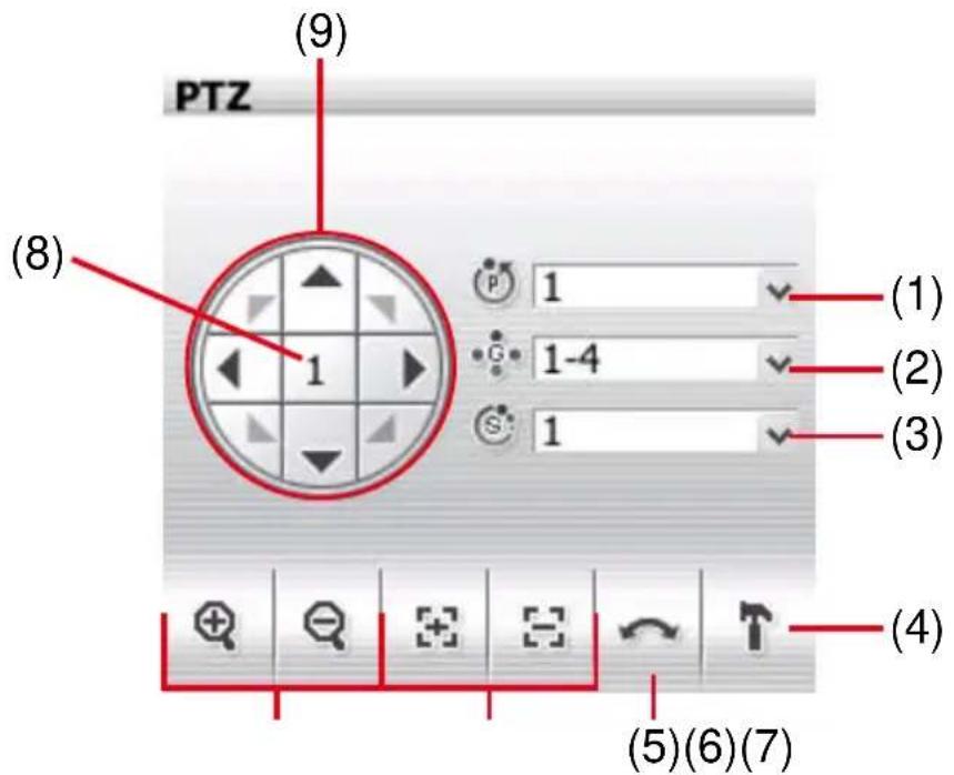
| Name | Function |
| (1) Camera preset position number | Move the PTZ camera to the preset point. |
| (2) Group AutoPan | Select to automatically operate PTZ camera in group. |
| (3) Direction buttons' moving speed | Adjust the moving speed of the PTZ camera lens. This speed will apply to the (9) Direction buttons' moving speed only. |
| (4) Setup | Click it to switch to PTZ setup page. |
| (5) AutoPan | Operate the PTZ cameras automatically based on the selected camera group preset position number. User needs to select the (2) Group AutoPan, then, click (5) Auto Pan button. |
| (6) Zoom +/- | Zoom in and out the image. |
| (7) Focus +/- | Adjust the focus manually to produce clear image. |
| (8) Camera ID | Display the PTZ camera number that is being operated. |
| (9) Direction buttons | Move and position the focal point of the PTZ camera. The support of direction button depends on the PTZ camera. |
2.9 Record Management

- The recording schedule is always record in default.
-
If the storage path is not set, the NVR/DVR system couldn't record.
-
Click Setup tab.
- Then, select Record Management.
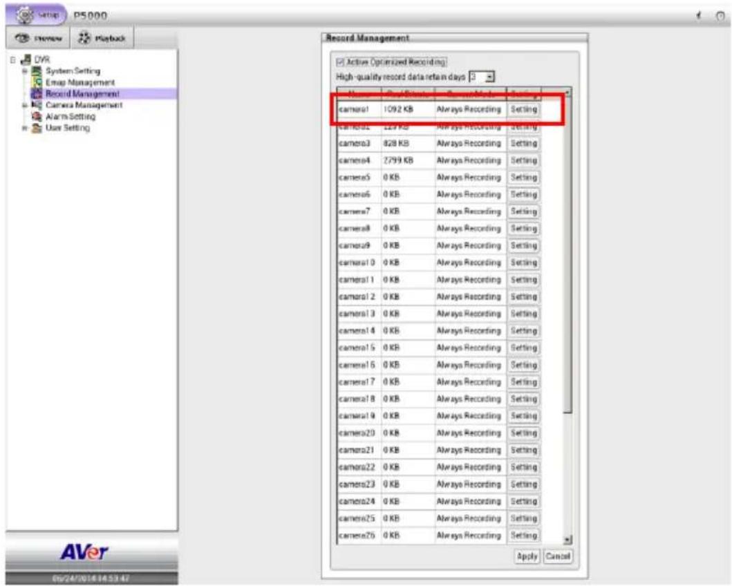
- Mark Active Optimized Recording to enable dual stream recording.
- Select the day for High-quality record data retain days to recycle the high quality record data.

Must enable Active Optimized recording before selecting high-quality record data retain days.
- Click the Setting button of camera that user wants to setup the recording schedule.
- In Record Schedule window, select the Recording Mode first. The recording modes are listed in following:
- Always Recording
Record the video from the selected camera and save it to the designated storage path.
- Event Recording
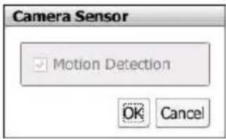
Start recording the video from the selected camera only when the system detects movement. Once a motion is detected, the system automatically saves the previous frames and stop based on the Start Record Prior (0\~10 seconds) and Stop Record After(0\~999 seconds) settings. Click Detail button to view event recording items. Now, only support motion recording on Event recording mode.
- Smart Recording
Automatically switch to recorded once a motion is detected and if there is no motion, it records at key frame only.
- No Recording
The system won't do any recording.
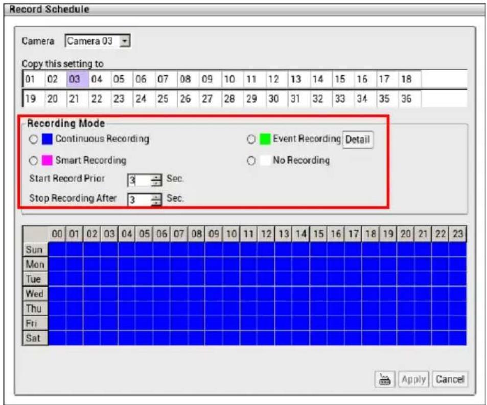
- After selecting the recording mode, select date and time on date time table.
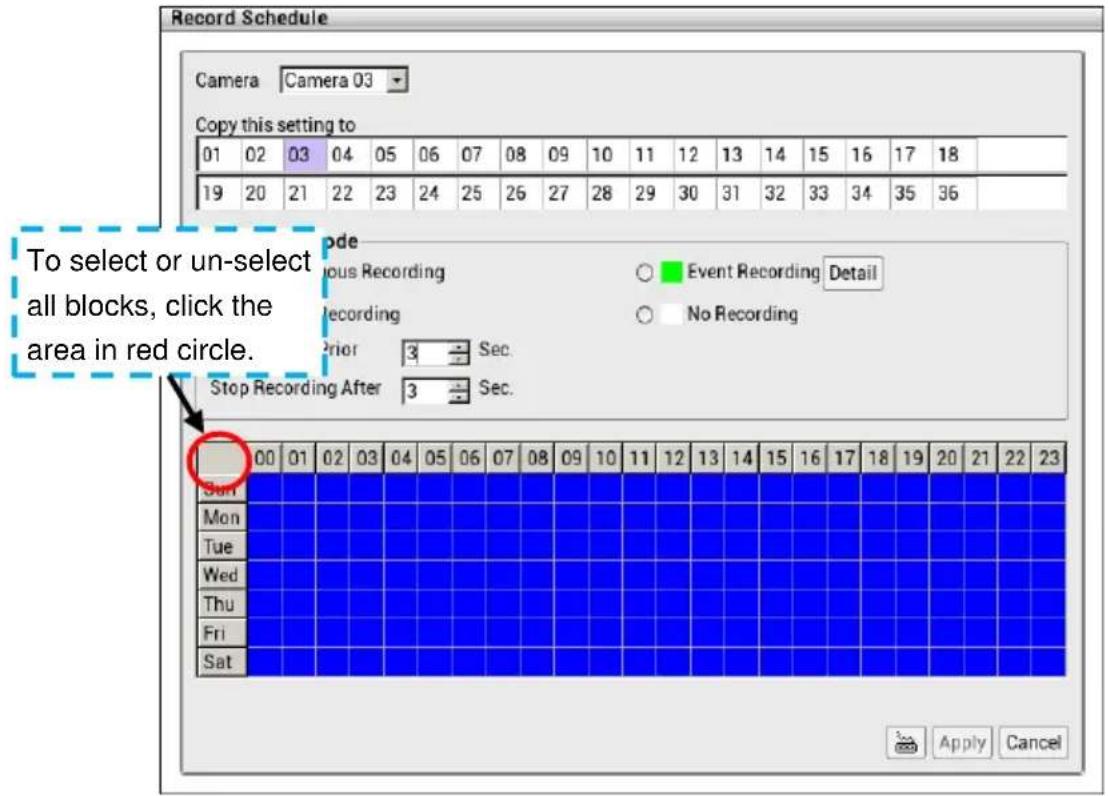
- If user wants to apply this record schedule to other or all camera channels, uses Copy this setting to function to apply to other camera channel.
| Copy this setting to | ||||||||||||||||||
| 01 | 02 | 03 | 04 | 05 | 06 | 07 | 08 | 09 | 10 | 11 | 12 | 13 | 14 | 15 | 16 | 17 | 18 | |
| 19 | 20 | 21 | 22 | 23 | 24 | 25 | 26 | 27 | 28 | 29 | 30 | 31 | 32 | 33 | 34 | 35 | 36 | |
- Click Apply to save the recording schedule.
- To stop recording, select "No Recording" and click on the date and week to disable the recording; then, click Apply to save the changes.
2.10 Alarm Schedule Setting
Setting up the schedule for alarm action that user has setup in Alarm setting (see also Chapter 2.12). According to the alarm schedule, the alarm actions will be active and alarm will be issued when action has matched the conditions.
- Click Setup tab > Alarm Setting. And select Alarm Schedule tab.
- In Alarm schedule page, select the Enable and click on the date and time to setup the schedule.
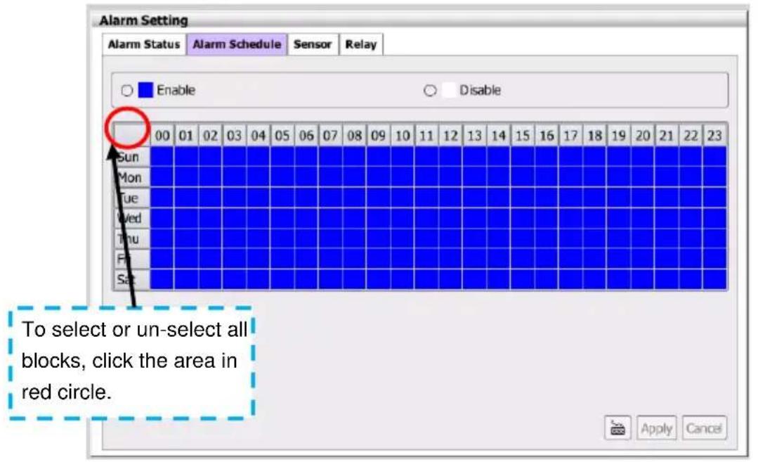
- Next, click Apply to save the setting. To disable the alarm schedule, select "Disable" and click on the date and time table and click Apply to save the changes.
2.11 Backup Setting
Backup the recorded files to external USB pen drive. In Backup setting, user can select different channels or time period to backup at the same time. The backup files can be playback on PC by Qplayer application that is included when backup. Playing backup file on PC refer to Chapter 5.
- Click Playback tab to switch to playback mode.
- Click Backup ( ) and the Backup dialog box is appeared.
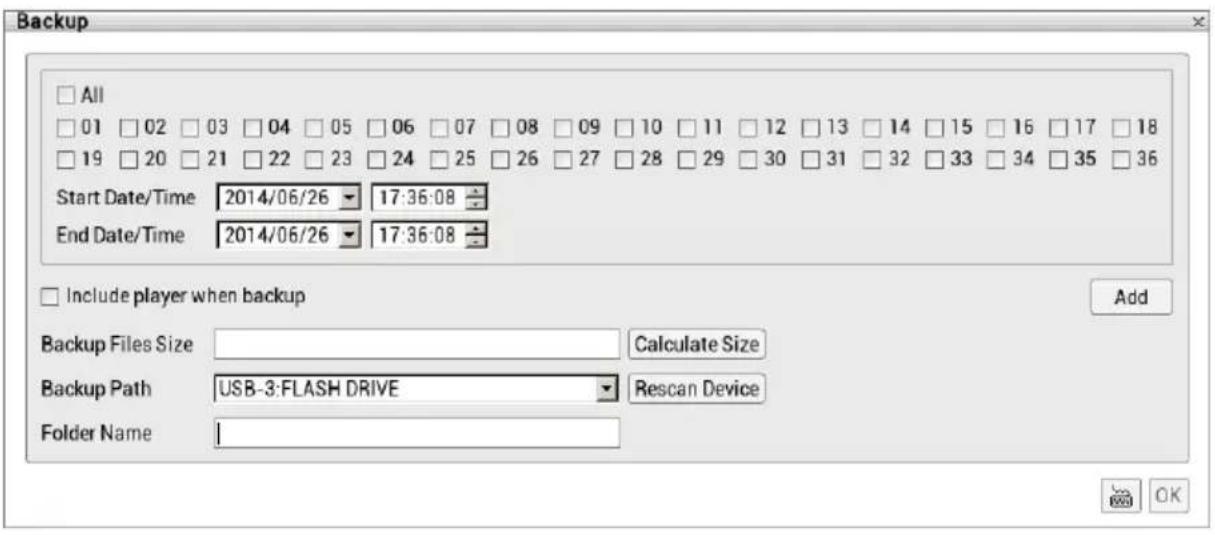
- In Backup dialog box, select the following settings:
■ Channel: Select the channels that user wants to backup. Mark All to select all channels.
■ Select date and time: Select the date and time period that user wants to backup.
■ Include Player when backup: Including the player for playback the backup file on PC.
■ Backup File Size: Display the size of the backup file. If there is more than one backup file, there will be total size of all backup files. Click Calculate Size button to calculate.
■ Backup Path: The path for saving backup file. The NVR/DVR system will detect and list it. If there has more than one backup path is available; user can select it from drop-down list.
■ Folder Name: Give a name of back folder that will be stored backup files in USB pen drive. To enter folder name, click virtual keyboard and enter the name.
- After selecting the backup file conditions, click OK to start backup.
- User can backup multiple recorded file (different channels and different time period) at the same time. Repeat the above steps to create the backup file and click Add button. The different backup files are distinguished by Folder Name that user has given. The multiple backup files limit is 3 files at the same time.
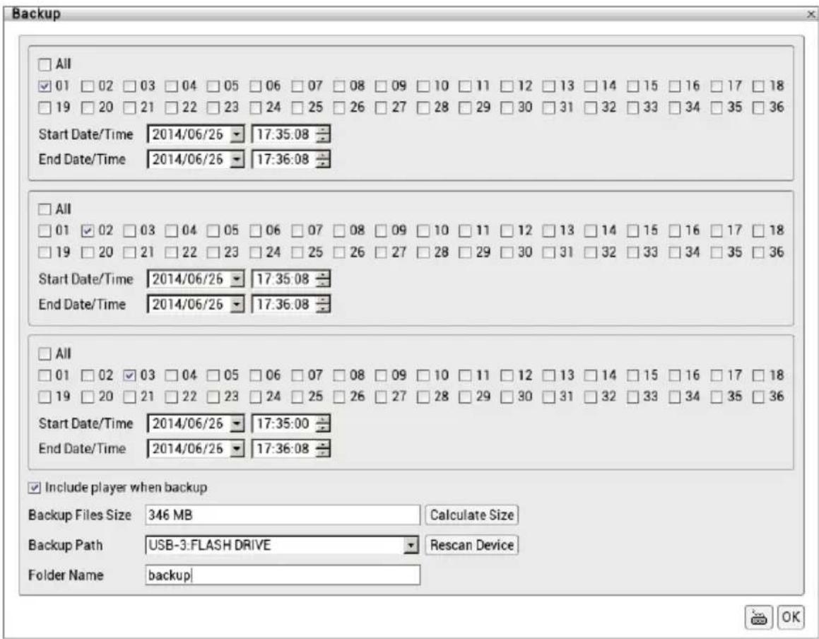
- When all backup files have created, click OK button to start archiving the selected file to USB pen drive.
2.12 Alarm Setting
To setup an alarm setting, user needs to complete following steps:
- Setting up the alarm conditions (see also Chapter 2.11.1).
- Setting up the alarm actions (see also Chapter 2.11.2).
- Setting up the alarm schedule (see also Chapter 2.9.2).
In the following chapter, it describes how to setup the alarm condition and action.
2.12.1 Setup Alarm Condition
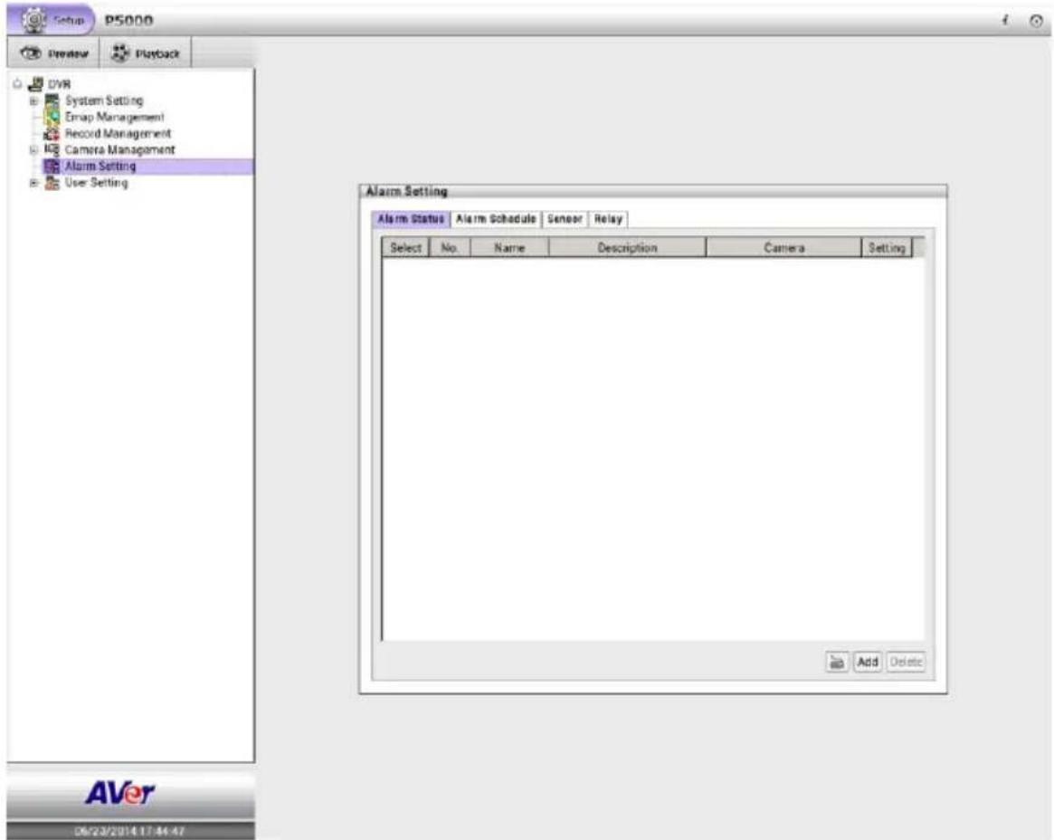
- Click Setup tab > Alarm Setting.
- User should see the Alarm Setting dialog box is displayed.
-
Next, click Add to create a new alarm condition setting.
-
In No. column displays the alarm setting number. The number of alarm is assigned by NVR/DVR system in default.
- Enter alarm name and description for this alarm setting in Name and Description column.
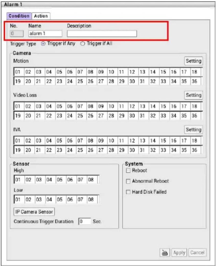
- Next, select "Trigger if any" to activate alarm if system falls to one of the conditions or "Trigger if all" to activate alarm if system falls to all conditions.

- In Camera section, select and click on the camera number in Motion, Video Loss, IVA to set the condition for the system to alarm.

If IVA alarm status is not enabled, the IVA functions that user has enabled will not issue any alarm when IVA functions have triggered.
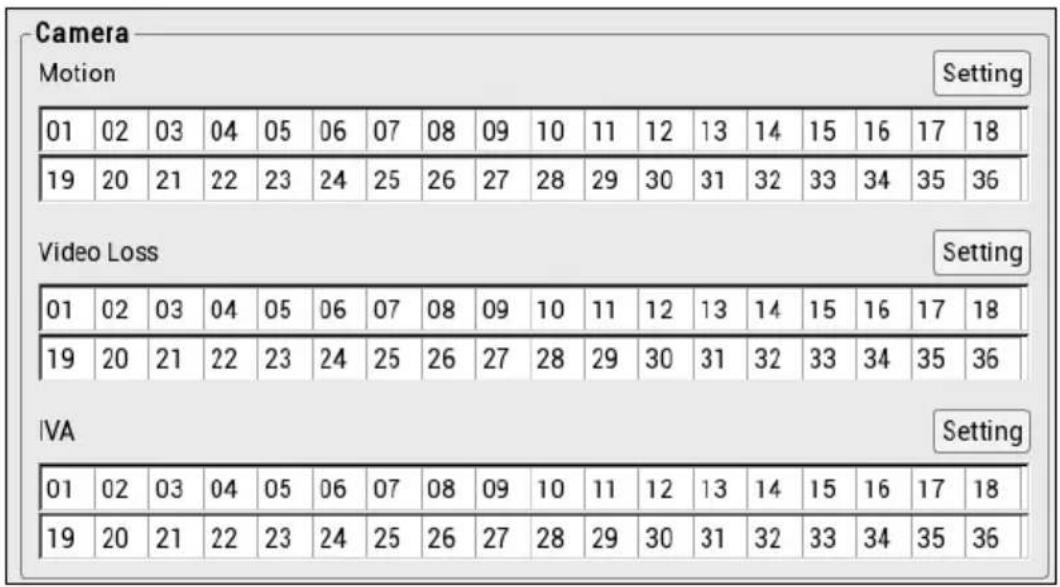
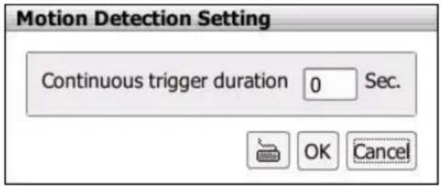
- Motion: select and click on the camera number (01 to 36) to set the condition for the system to alarm. Click the Setting button to setup the system to send out the alarm when motion is detected and last the time that user has entered in Continuous trigger duration. The time range is 0\~300 seconds.
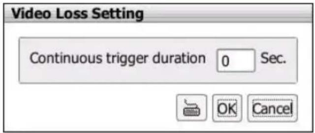
- Video Loss: click the camera number (01 to 36) to set the alarm condition when video is lost. Click the Setting button to setup the system to send out the alarm when video is lost and status last the time that user has entered in Continuous trigger duration. The time range is 0\~300 seconds.
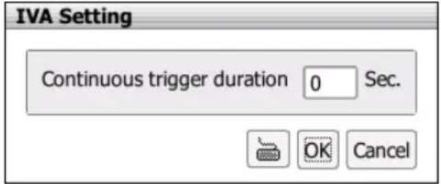
- IVA: click the camera number (01 to 36) to set the alarm condition when IVA functions are triggered. Click the Setting button to setup the system to send out the alarm when IVA functions have triggered and status last the time that user has entered in
Continuous trigger duration. The time range is 0\~300 seconds.
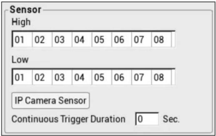
- In Sensor section, select and click on the sensor number to set the condition for the system to alarm. If the sensor normal status is high, set the sensor condition to low.
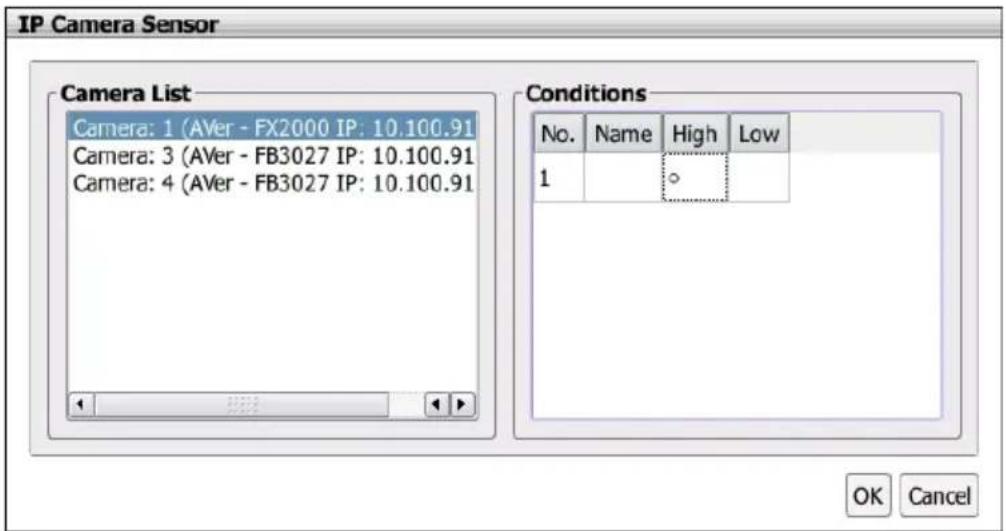
- IP Camera Sensor: To adjust sensor high/low that is connected on the IP camera.
- Continue trigger duration: Set a time period that when sensor has been trigger and stay in the same status for that period, then the alarm will be sent out.
- In System section, mark the check box to set the conditions that are caused by system.
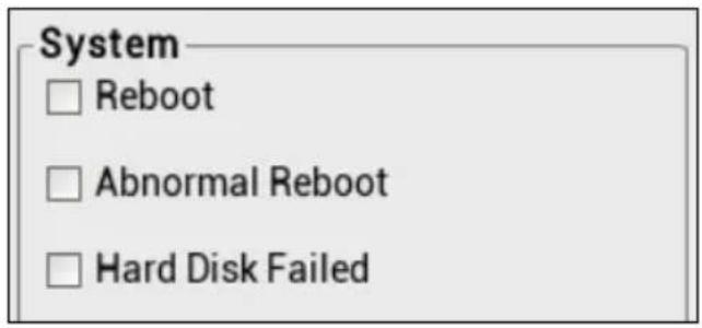
- Reboot: when the NVR/DVR system reboot without abnormal condition, the system will send out the alarm message.
- Abnormal Reboot: when the NVR/DVR system reboot in irregular condition, the system will send out the alarm message.
-
Hard Disk failed: when the hard disk doesn't work normally, the system will send out the alarm message.
-
After setting all alarm conditions, click Apply to save the settings.
- Next, user needs to set the alarm action when alarm has triggered. Please refer to Chapter 2.12.2.
- To modify the alarm condition setting, click Setting button of Alarm # that user has created. Remember to click Apply to save the changes after modification.
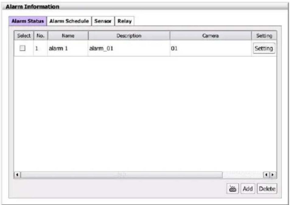
- To delete the alarm #, select the alarm # that user wants to delete and click Delete button.
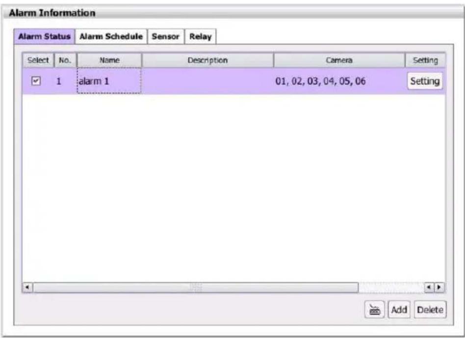
2.12.2 Setting Alarm Action
Setup the alarm action for system to perform when the alarm condition has been triggered.
- Click Setup tab > Alarm Setting.
- Then, click Setting button of Alarm # that user has created in Alarm Information dialog box. Also, user can select the Alarm# from the list under Alarm Setting.
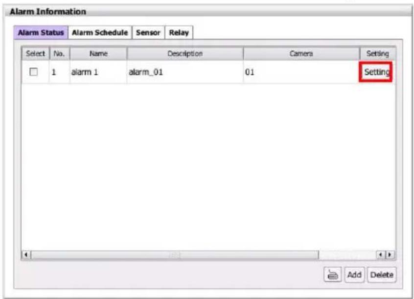
- In Alarm Setting page, select the Action tab to switch to alarm action page.
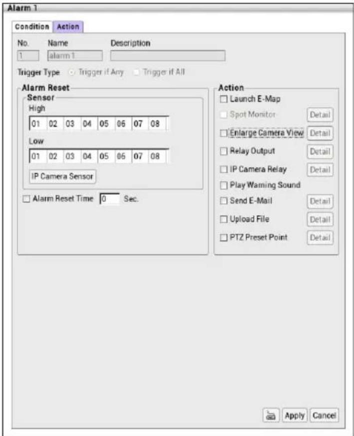
-
The No., Name, Description, and Priority column display the current alarm's information. The Trigger Type displays the current alarm's trigger condition.
-
In Alarm Reset section, click the camera number to set the reset condition of alarm. Once alarm is reset, all alarm action will stop at the moment. If the sensor normal status is high, set the alarm reset condition to low.
IP Camera Sensor: To adjust sensor high/low that is connected on the IP camera.
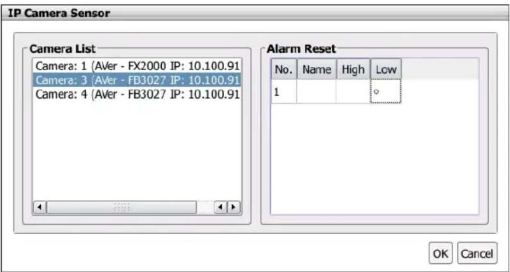
- Alarm Reset Time: Set a time for the alarm auto reset. When an alarm happen such as motion detected and video loss, the alarm will reset at the alarm reset time.
-
In Action section, user may now set the alarm action for the system to perform when the alarm condition is activated.
-
Launch E-Map: Display mini E-map on the screen.
- Enlarge Camera View
Switch to only display video in Preview mode from where the alarm is activated.
a. Select the camera from drop down list to specify which camera video to be enlarged on screen when the alarm is triggered.
b. Retrieve time: set the waiting duration before system switching back to original Preview mode. If the retrieve time is un-set, the alarm video will keep enlarging until user switch back to Preview mode manually. The retrieve time range is 0\~300 seconds.
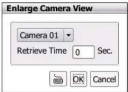
- Relay Output
Set to enable/disable the relay operation when the alarm is activated and to extend additional time in second before it stops the relay operation.
a. Beside the Relay Output check box, click Detail.
b. In the Relay Output dialog, select from the available relay list and in the Status column, set to on/off the relay operation when the alarm is activated.
c. In the Retrieve time check box, you may enable/disable to extend the relay operation time and set the duration in second (0 \~ 300 seconds).
d. Click OK to exit and accept the setting and Cancel to exit without saving the setting.
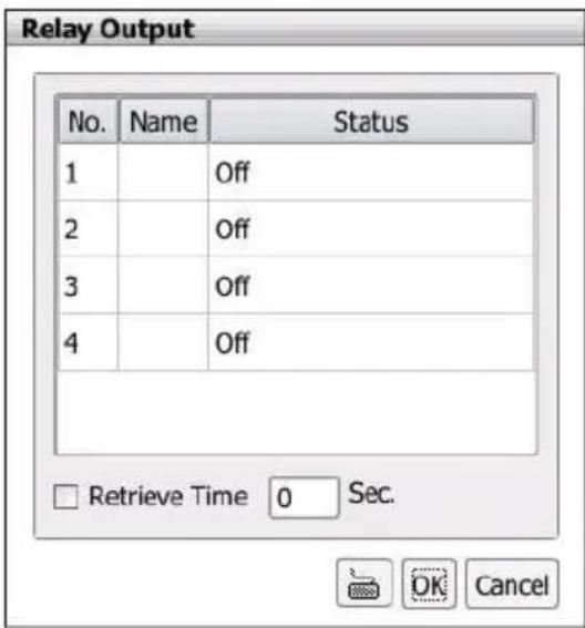
- IP Camera Relay
Set to enable/disable the relay operation when the alarm is activated.
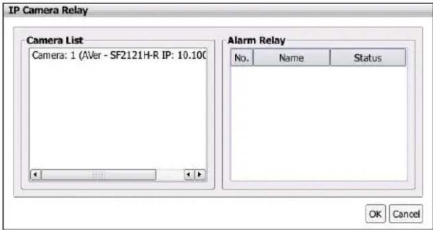
- Play Warning Sound
Play alarm sound.
- Send E-mail
Send an electronic text message. Beside the Send Email check box, click Detail. In the E-mail Setting dialog box, click OK to exit and save the setting and Cancel to exit without saving the setting.
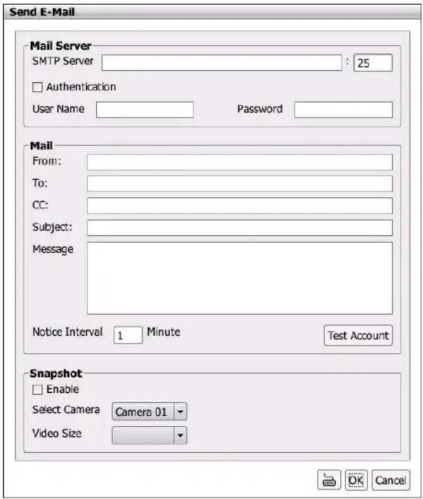
Mail Server
Enter the SMTP Server and port. If your e-mail system requires user identification, enable Authentication check box and enter ID and Password.
Fill the mailing information. Click Test Account button can exam the mail is workable or not.
√ From: Enter the sender e-mail address.
√ To and CC: Enter the recipient email address and separate it with comma or a semicolon (;).
√ Subject: Enter the message title.
√ Message: Type the message.
√ Notice Interval: Set a time gap for mail re-sending when mail has failed to send.
■ Snapshot
When send out the email, the NVR/DVR system will snapshot image of the selected camera channel.
√ Select Camera: Select the channel that will be snapshot when alarm email is sending out.
√ Video Size: Select the size of vide that will be taken when snapshot. Auto means default size that chosen by NVR/DVR system.
- Upload File
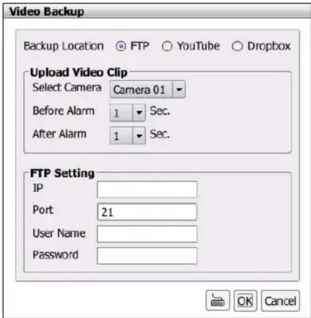
√ Backup Location: YouTube and Dropbox cannot be enabled at the same time.
FTP: Upload the alarm video clip to the FTP site that user has setup.
YouTube: Upload the alarm video clip to the Youtube space that user has setup.
a. Get a Google account. Go to Google website and follow the instruction to get a Google user account.
b. Copy the below URL to your Google browser.
http://www.aver.com/Youtube
c. Using your Google account to login and click "Allow" to enable Google WAN storage function.
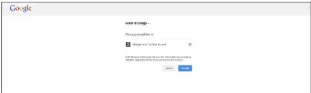
d. Then, user will see the authorization code is displayed. Keep this web page open and open a new web page.
e. Enter the below URL to enter authorization code. Please make sure your PC can connect to NVR/DVR server through internet. http://NVR/DVR IP/oauth2.html ex: http://10.1.1.3/oauth2.html.
f. Next, NVR/DVR server will require login authentication. Enter the login username and password of NVR/DVR server.
g. Then, authorization code input page is displayed. Copy the authorization code into the Authorization Code column and click Apply.
h. Next, go to alarm action setting to setup FTP transmission via FTP(see also Chapter 2.11.2).
Dropbox: Upload the alarm video clip to the Dropbox space that user has setup.
a. Get a Dropbox account. Go to Dropbox website and follow the instruction to get a Dropbox user account.
b. Copy the below URL to your browser. http://www.aver.com/Dropbox
c. Using your Dropbox account to login and click "Allow" to enable Dropbox WAN storage function.
d. Then, user will see the authorization code is displayed. Keep this web page open and open a new web page.
e. Enter the below URL to enter authorization code. Please make sure your PC can connect to NVR/DVR server through internet. http://NVR/DVR IP/oauth2.html ex: http://10.1.1.3/oauth2.html.
f. Next, NVR/DVR server will require login authentication. Enter the login username and password of NVR/DVR server.
g. Then, authorization code input page is displayed. Copy the authorization code into the Authorization Code column and click Apply.
h. Next, go to alarm action setting to setup FTP transmission via FTP (see also Chapter 2.11.2).
√ Upload Video Clip
Select Camera: Select the camera that the images will be captured and send when the any alarm is triggered.
Before alarm (sec.)/After Alarm: To send the recorded image before and after alarm occurs, enter the time that before alarm occurs in Before alarm (sec.) and After alarm.
√ FTP Setting
IP: Enter FTP server's IP address.
Port: Enter the port number of FTP connection.
ID& Password: Enter the ID and Password that use to login FTP server.
- PTZ preset point
Position the PTZ camera based on the preset point setting. Beside the PTZ preset point check box, click Detail. In the Trigger PTZ Preset Setting dialog box, select the PTZ camera number then select the Enable check box. Select the position of the PTZ camera when the alarm is activated and ended. For the PTZ camera end point, user can also select on preset position or Auto Pan between preset position groups.
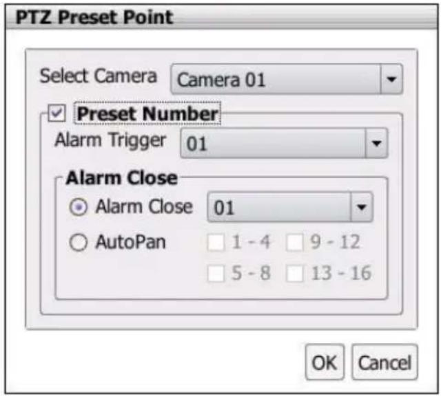
-
After setup all alarm actions, click Apply to save the settings.
-
To modify the alarm condition setting, click Setting button of Alarm # that user has created. Remember to click Apply to save the changes after modification.
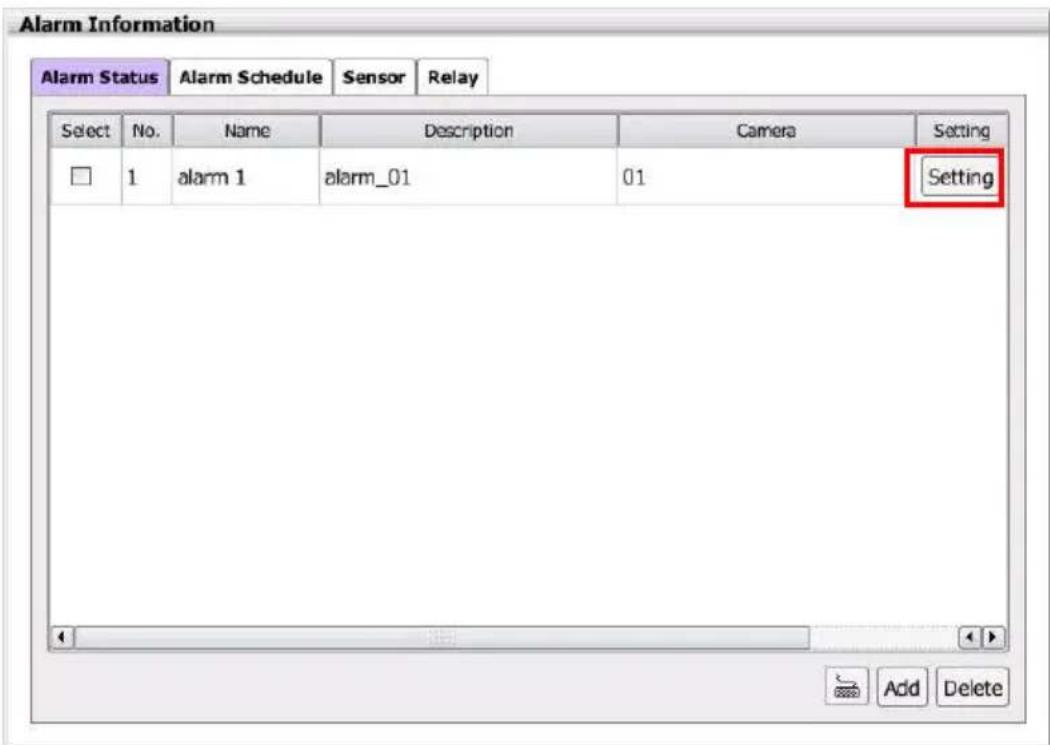
2.13 User Account Setting
Only administrator level authority can access User Setting. The maximum user accounts are 32.
2.13.1 Creating an User Account
- Click Setup tab.
- Then, click User Setting and the User Information dialog box is displayed.

The Admin is default user and cannot be deleted.
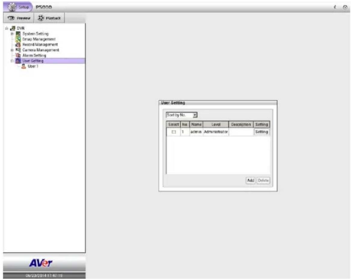
-
In User Information dialog, click Add to add a new user account.
-
In User Setting dialog, Select and fill in the following information.
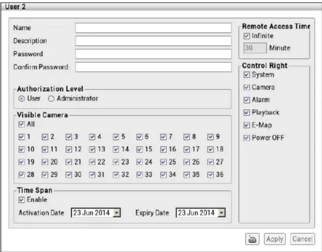
■ Name: Enter the user name.
■ Description: Enter the user description.
■ Password: Enter the user password.
■ Confirm Password: Enter the same user password for confirmation.
■ Authorization level: Select the status of the user. Administrator has full authority of control rights.
■ Visible Camera: Select the camera number that would allow the user to access or view. To select all the cameras, enable the ALL check box.
■ Remote Access Time: Enable Infinite check box to access NVR/DVR without time limit. If you want to set time limit, un-mark and enter the number of minutes in Minute text box.
■ Control Right: Enable the items that would allow the user to access.
■ Time Span: Set the user account a specific time period that user only can use given account to login NVR/DVR program in that specific period. Mark Enable check box and select the Activation Date and Expiry Date.
- Click Apply to save the account setting. The user account is list in User Setting list.
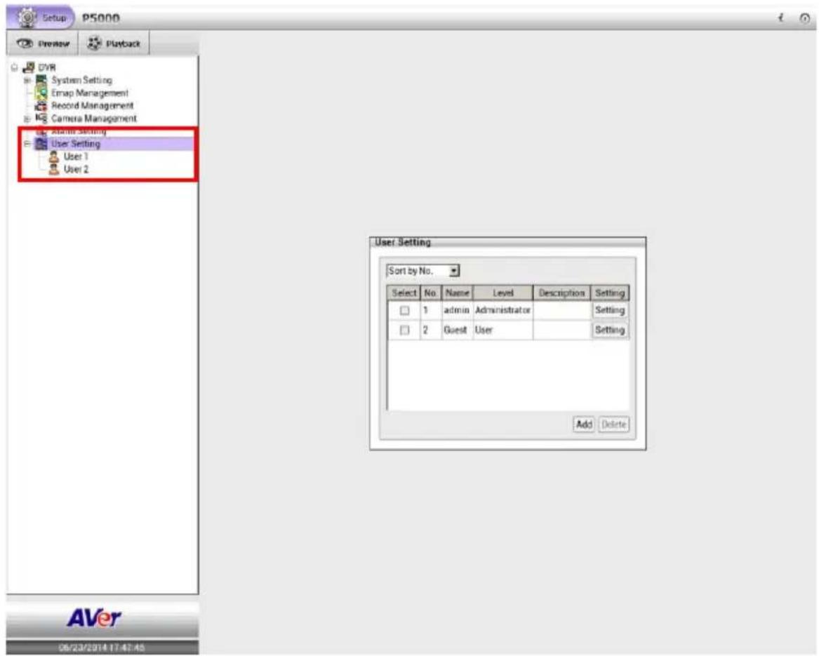
- Adding another user account, repeat above steps.
- Modifying the user account; click Setting of user account in User Information dialog.
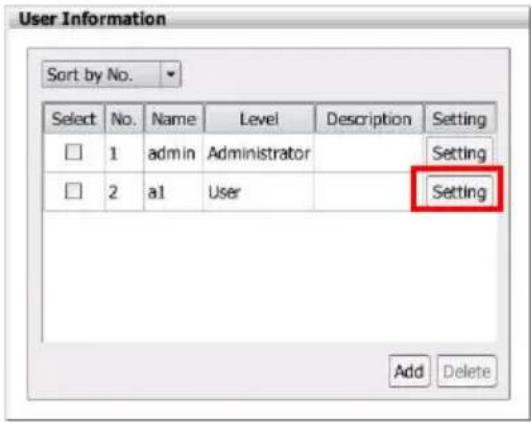
2.12.1 Deleting an User Account
User can remove un-wanted or expired user account.
- Click Setup tab in Preview mode.
- Then, click User Setting in Advanced NVR/DVR Setting section and the User Information dialog is displayed.
- Mark the user account in User Information dialog; then, click Delete button.
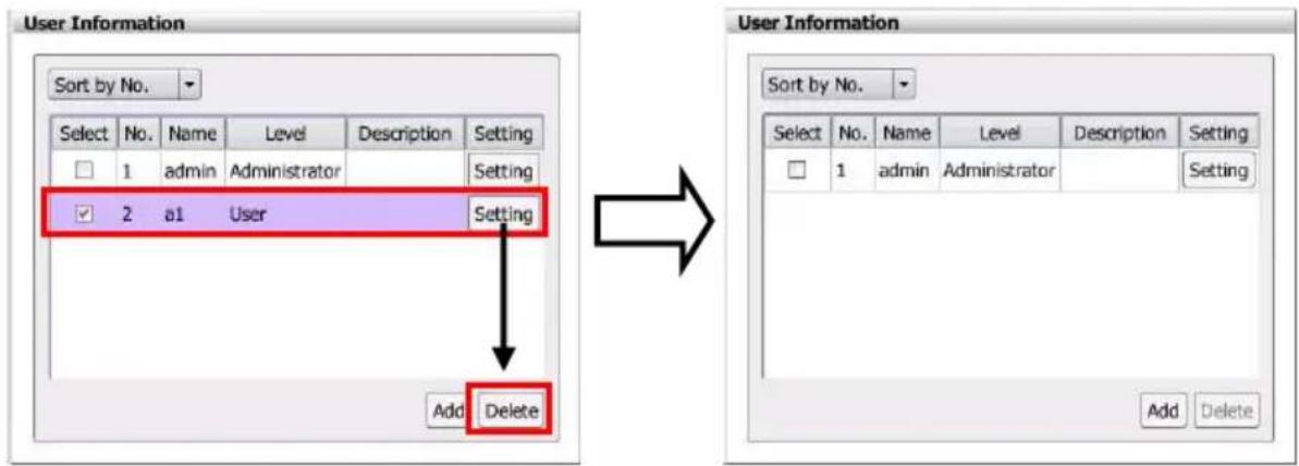
2.14 I/O Setting
Setup I/O device status.
2.14.1 Sensor Setting
- Click Setup tab > Alarm Setting > Sensor tab.
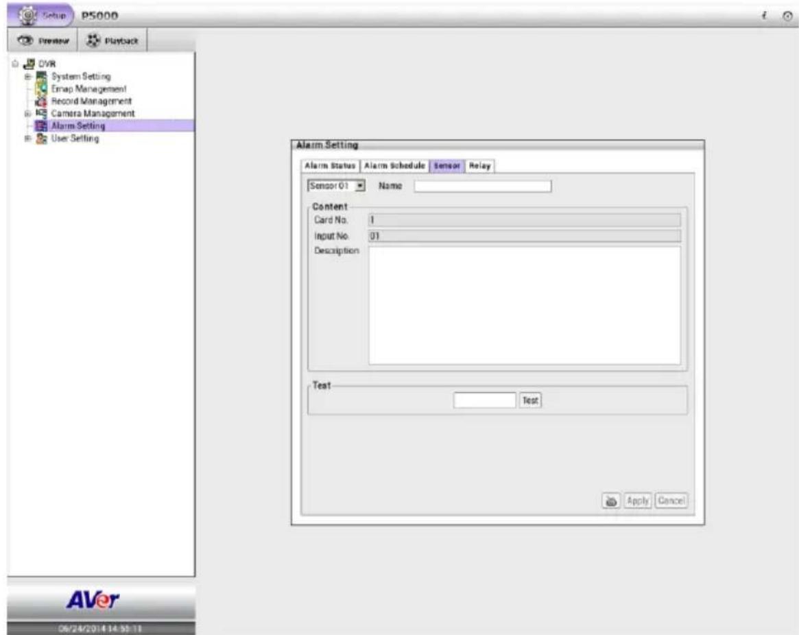
- Click the drop-down list and select the Sensor #
- Enter sensor name in Name column.
- The system automatically detects the card and input number. In the Content section, user can enter a short description of sensor in Description column.
- In the test section, click Test to check the sensor status. Red is high and Green is low.
- Click Apply to save the setting. To exit without saving the setting, click Cancel button.
2.14.2 Relay Setting
- Click Setup tab > Alarm Setting > Relay tab.
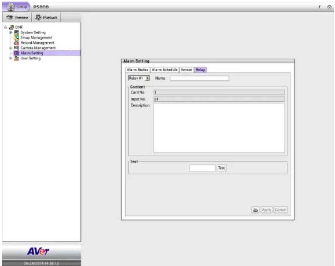
- Click the drop-down list and select the Relay #.
- Enter relay name in Name column.
- The system automatically detects the card and input number. In the Content section, user can enter a short description of relay in Description column.
- In the test section, click Test to trigger relay. Red is high and Green is low.
- Click Apply to save the setting. To exit without saving the setting, click Cancel button.
2.15 Emap Setting
E-Map can hold up to 8 maps in *.jpg or *.bmp format. User may locate the camera, sensor and relay on the map.
2.15.1 Setting Emap
- Click Emap Management.
- The Emap dialog box will appear on screen.
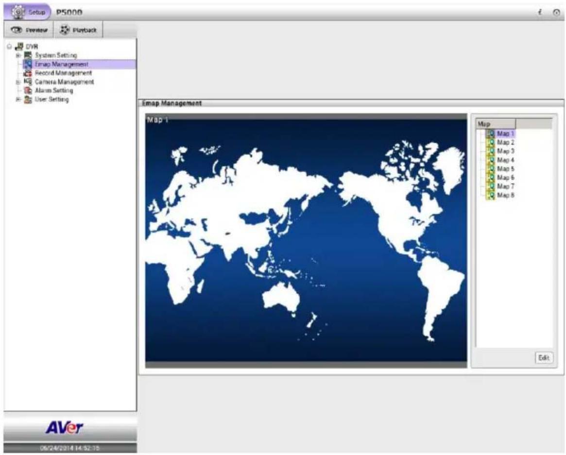
- Click Edit button to switch to Emap setup mode.
- Then, click the Map number (1 to 8) that user want to setup.
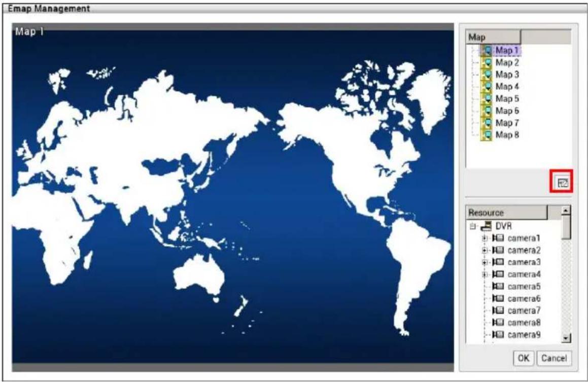
- Next, click icon to setup name of Emap and load a map figure. When the Emap Setting dialog box appears, click the open file icon ( ) to locate and select the map Enter a name for this Emap in Name column. Click OK to save the setting.
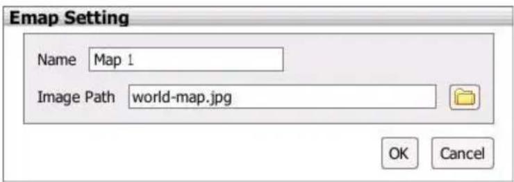
- When the inserted map appears on the Emap screen, user may now drag the camera, sensor, and relay icons to its place on the map. Icons on the map can be relocated anywhere. If user is going to locate the icon on the map to other area, right-click on the icon on the Emap and click remove to put the icon back to the Resource list.

The available icons are look like (Camera), (Sensor), (Relay) and un-available icons are look like (Camera), (Sensor), (Relay).
2.16 iPOS Setting
Set from which camera screen to display the data from the POS equipment. Click Setting, to set the POS Console Setting.
- Click Setup tab. Click + to expand the System Setting list and select Hardware Device.
- User should see the Hardware Device Setting dialog box is displayed.
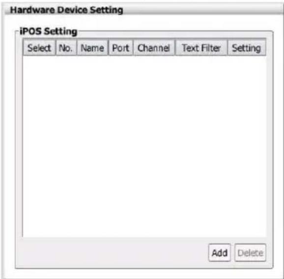
- In the Hardware Device Setting dialog box, click Add to set a new POS setting.
- In the POS Mapping dialog box, fill and select the following settings. Click OK to save the settings and Cancel to exit without saving the new setting.
■ Name: Enter a name to identify the POS.
■ Protocol: Select the protocol.
- Skip first: Set the number of lines you want to be removed.
■ Font Color: Select the text color of the POS data.
■ Port Setting: Select the Local(Com port) where it is connected and Baud Rate.
■ Map to Channel: Select to which camera number to display the transaction text.
■ Text Filter: Enter the word you want to be removed.
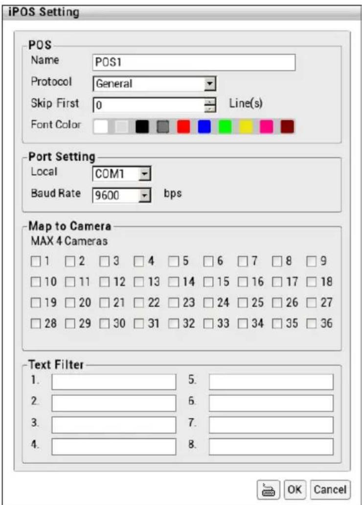
- To setup another iPOS setting, repeat the above steps.
- To modify the iPOS setting, click the Setting button of iPOS.
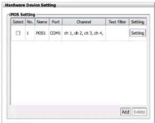
- To delete the iPOS, mark the iPOS and click Delete button.
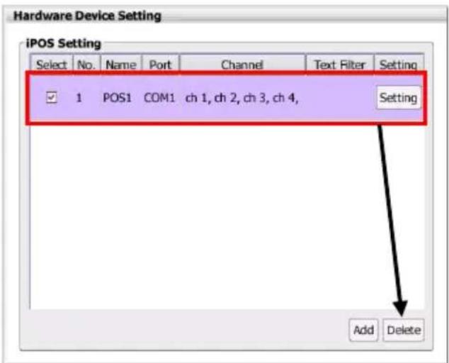
- To view the iPOS event log, refer to Chapter 2.16.3.
2.17 Log Viewer
Show the record of activities (alarm, event, iPOS) that take place in the system. User can view and search for specific log.
2.17.1 Using the Event Log Viewer
- Select the channel that user wants to search. Click the channel on screen.
- Click Event Log icon ( ) in preview mode.
- The Event Log Viewer dialog box is appeared and located at bottom of left side screen.

User can click icon to expand the Event Log Viewer dialog box on the screen.
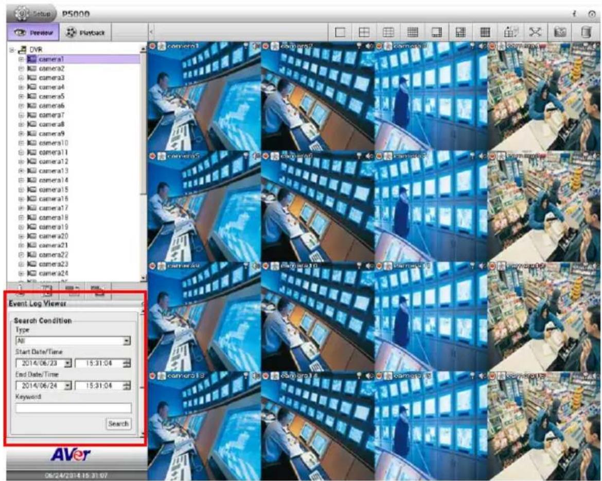
- To filter the logs, select and click the select Type -- System, Network, Operation, Event, or All.
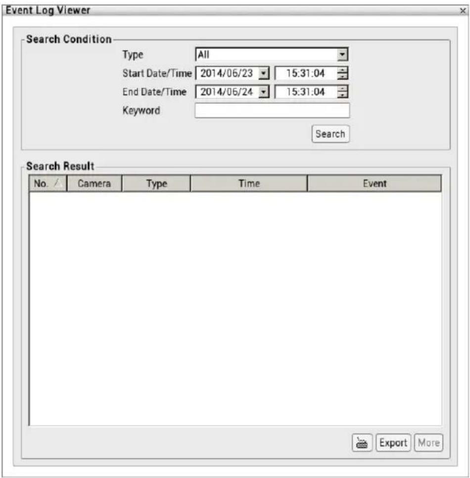
- Set the Start Date/Time and End Date/Time period to search the logs.
-
User also can search specific logs by specific Keyword.
-
Click Search button to start searching. The search results are displayed in the below column. Click More button to display more event logs.
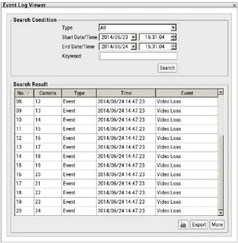
- Click on the event log can view the log video.
- Click Export button can output the log result list to external USB pen drive in *.cvs file format.
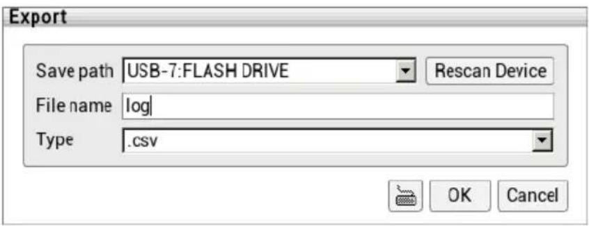
2.17.2 Using the Alarm Log Viewer
The alarm log viewer is both supported in preview and playback mode.
Viewing Alarm Event
Alert and display warning information.
- Click Alarm Log icon ().

- The Alarm Log Viewer dialog box is appeared and located at bottom of left side screen.

User can click 📄 on to expand the Alarm Log Viewer dialog box on the screen.
- Then, click Event tab to view all alarm events.
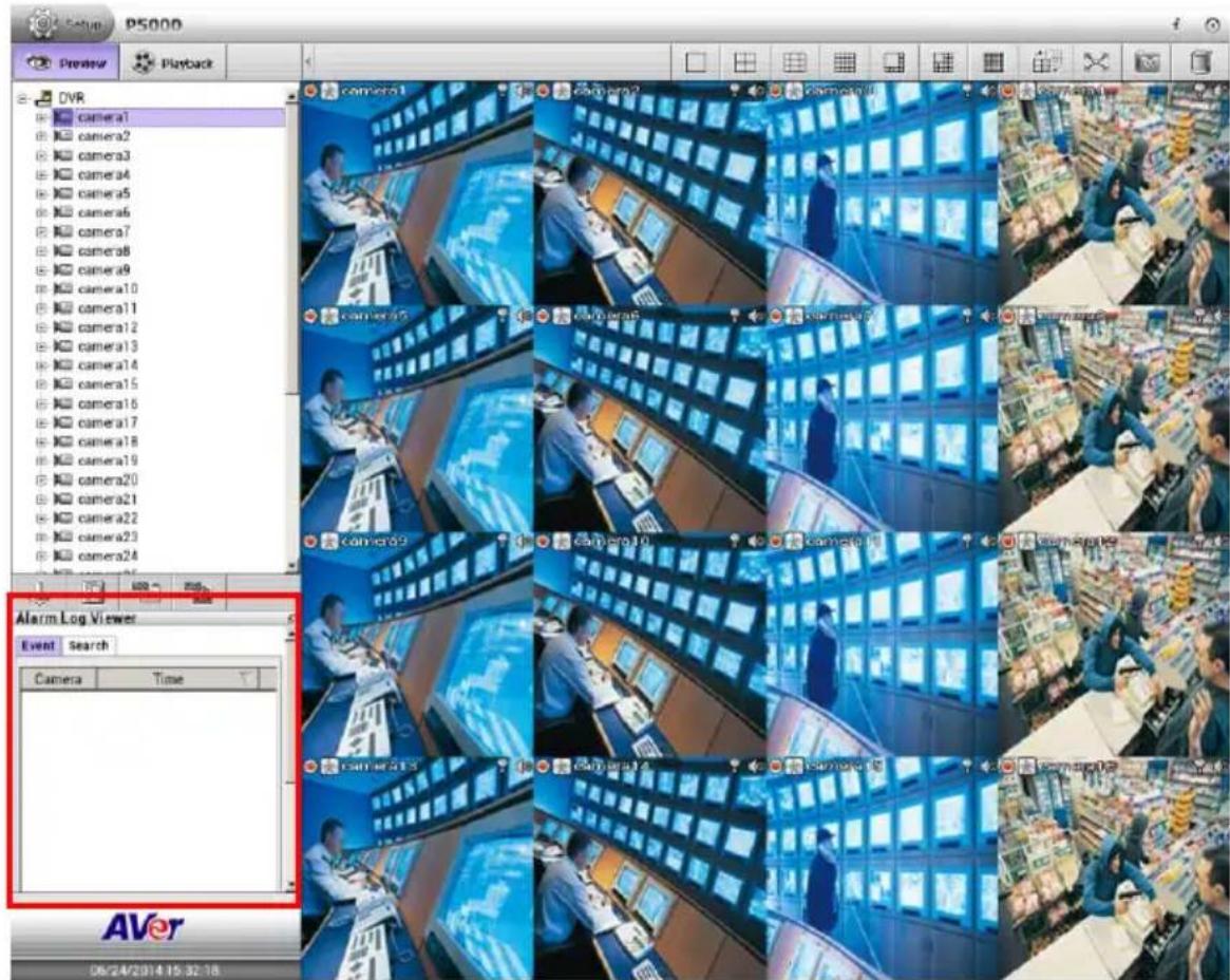
-
Clicking Alarm reset button to reset all alarm event status.
-
Clicking Refresh button to refresh the alarm events list.
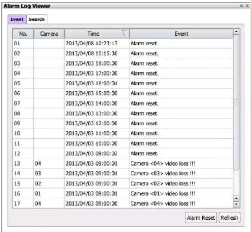
- Double-click on alarm event can playback the event video.
Searching Alarm Event Logs
Searching the specific alarm event.
- Click Alarm Log icon ().
- The Alarm Log Viewer dialog box is appeared and located at bottom of left side screen.

User can click 📄 on to expand the Alarm Log Viewer dialog box on the screen.
- Then, click Search tab in Alarm Log Viewer dialog box.
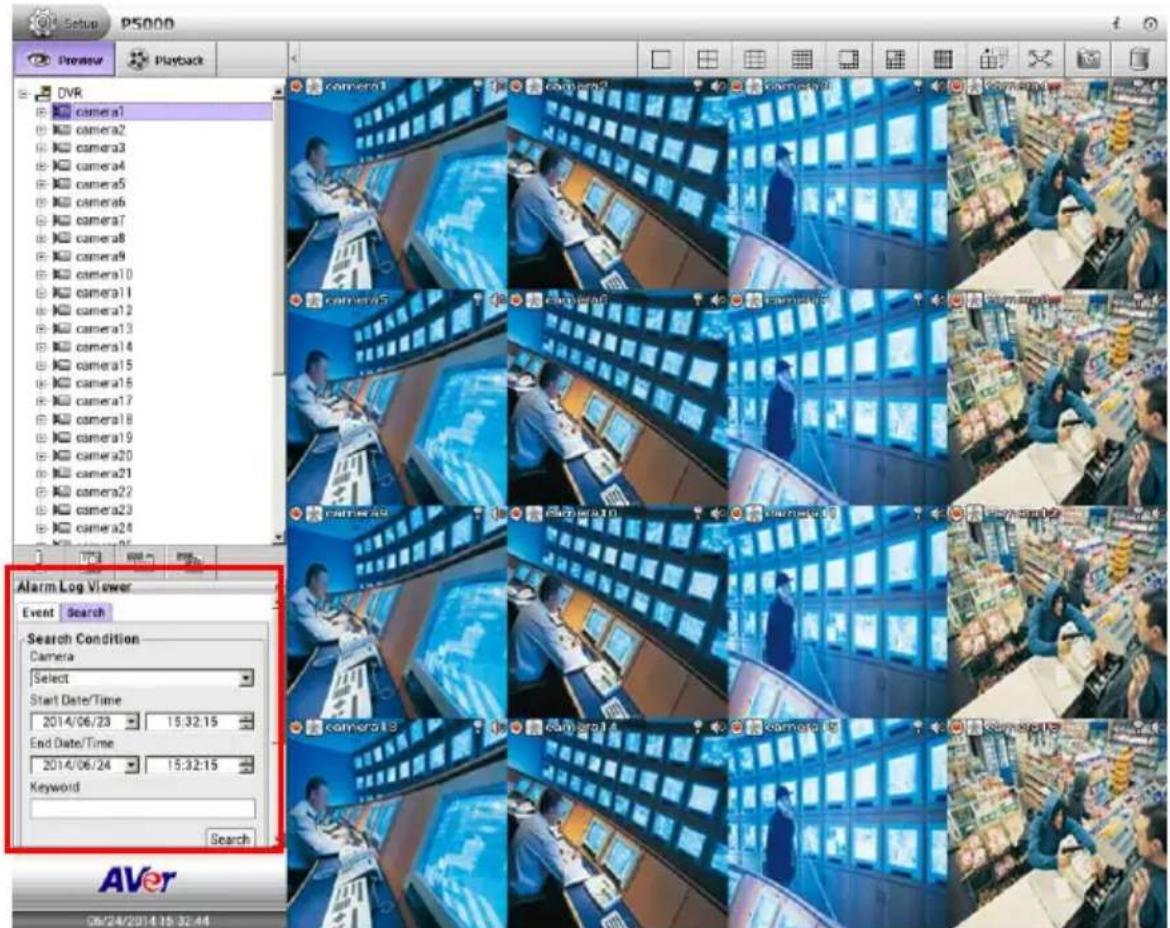
- In Alarm Log Viewer dialog box, select the Camera that user wants to search. Multiple cameras selection is allowed.
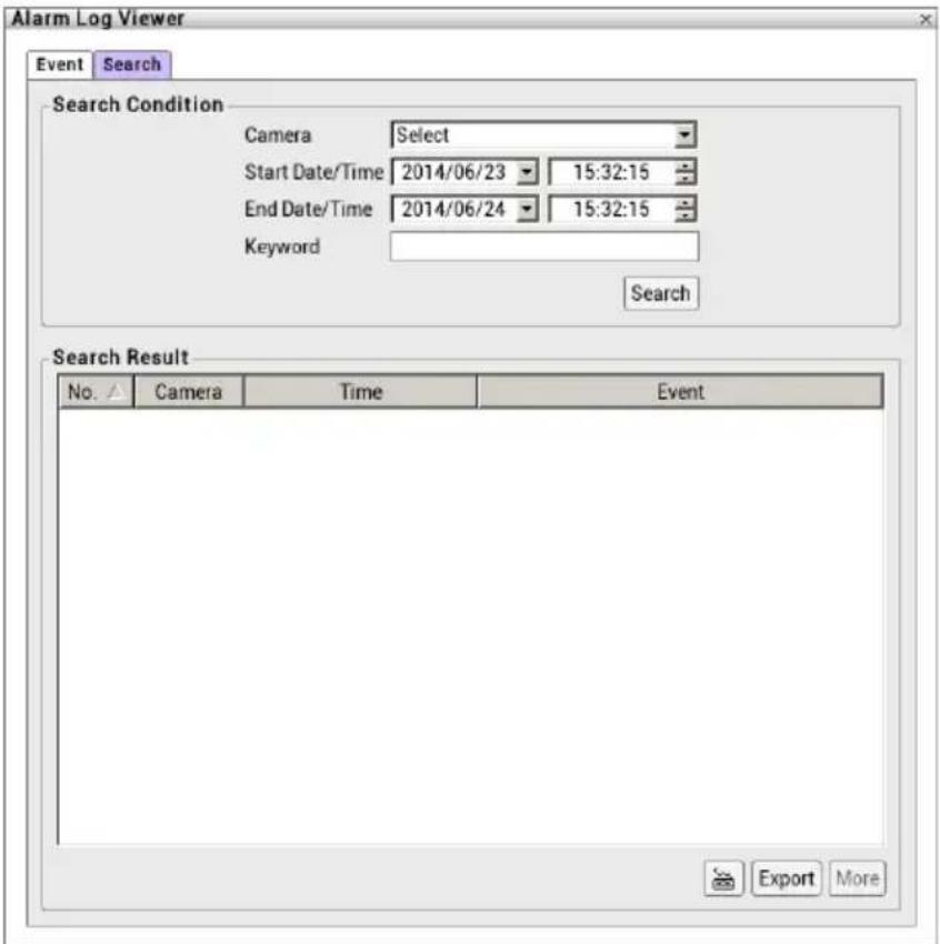
- Set the searching period at Start Date/Time and End Date/Time column.
- Searching by specific keyword, enter the keyword in Keyword column.
- Click Search button to start searching.
- The search result will list in below column. Click More button to display more event logs.
- Click Export button can save the search result list to external USB pen drive.
- Double-click on alarm event can playback the event video.
2.17.3 Using POS Log Viewer
Search the iPOS event. The POS Log viewer is both supported in preview and playback mode.
- Click POS Log ().
- The POS Viewer dialog box is appeared and located at bottom of left side screen.

User can click icon to expand the POS Log Viewer dialog box on the screen.
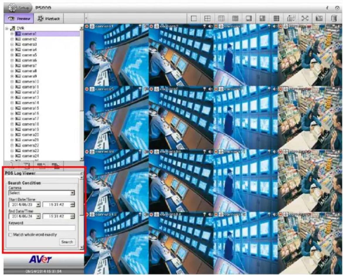
- In POSViewer dialog box, select the Camera that user wants to search.
- Set the searching period at Start Date/Time and End Date/Time column.
- Searching by specific keyword, enter the keyword in Keyword column. Mark Match whole words exactly option to 100% match the keyword that user has entered.
- Click Search button to start searching. The search result will list in below column. Click More button to display more event logs.
- Click Export button can save the search result to external USB pen drive.
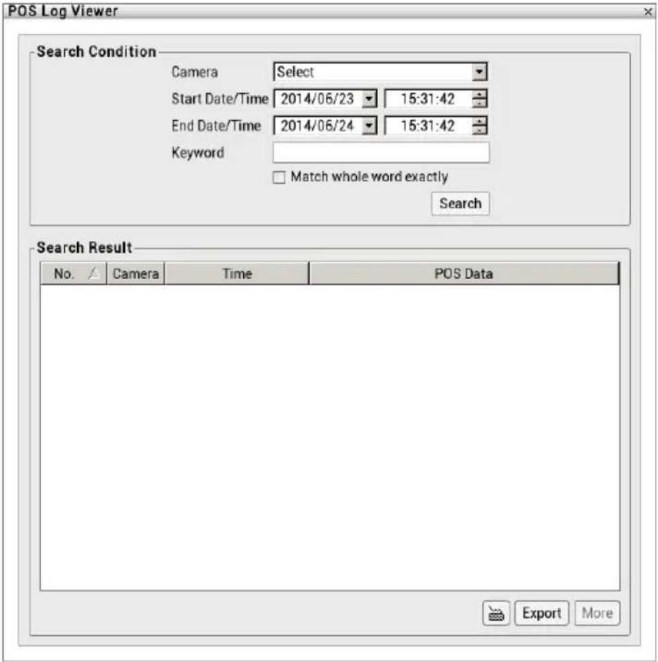
2.18 NVR/DVR System Tools
2.18.1 Hard Disk Calculator
Estimate the hard disk recording capacity. The result of calculation is a rough value which only for reference. The hard disk record capacity will be varied by the real record quality and complexity of video scene.
- Click Setup tab > System Setting; click + to expand the list and click Storage.
- In Storage Setting dialog box, click Hard disk calculator button.
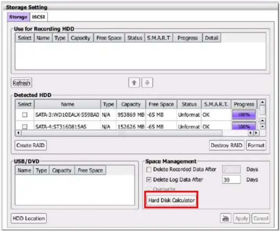
- In Hard Disk Calculator dialog box, enter the expect hard disk size or expect recording time in Expected HD Size(GB) or Expected Record Time(Days), and then click Calculate button. The Total Recording time(Days) column is shown the current hard disk recording capacity. Click OK to exit the hard disk calculator window. The hard disk calculation is based on the recording setup and current hard disk capability.
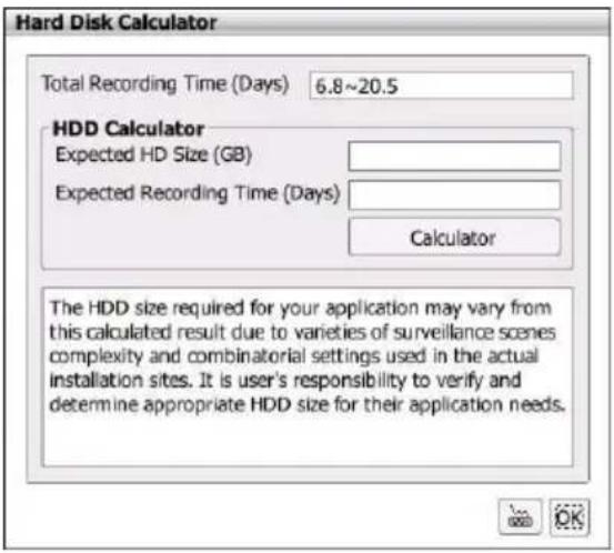
2.18.2 Using On Screen Keyboard
User can use the on screen Keyboard to enter require information in setting dialog box. Click to call out the on screen keyboard. For uppercase, click Caps button. To exit, click Esc.
![Esc 1 2 3 4 5 6 7 8 9 0 - = <= ` q w e r t y u i o p [ ] \ Caps a s d f g h j k l ; ' Enter Shift z x c v b n m , . /](/content/2026/05/1044351/images/d45237c9a5f902b1bd354441d5daca4aca4c05451dce7a8ecc1f5a7bce85c8bd.jpg)
Chapter 3 Monitoring the NVR/DVR
After setting up the NVR/DVR system, user can start to monitor the NVR/DVR in preview mode. The following chapters are going to describe the monitoring functions in preview mode.
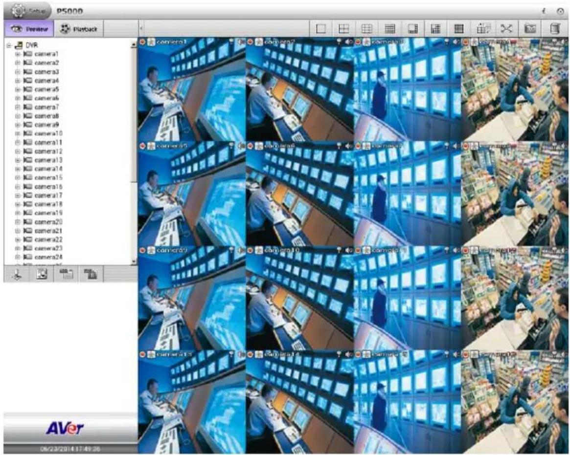
3.1 Managing Camera Channels
User can arrange the channel display position as user is desired.
Select the camera in Camera section. Then, drag the camera to the channel that user wants to be displayed. Next, User should see the live video on the channel screen.
The channels can be switched between each channel; just click the channel and drag the channel to the desire channel position. For example: Camera 01 switches to Camera 09; the Camera 01 will be Camera 09 position and the Camera 09 will switch to the Camera 01 position.
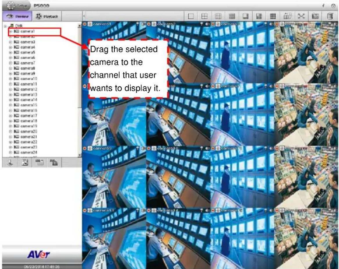
3.2 Meaning of Icons and Figures
■ The description of icons on each channel:
 | The icon is indicated the current recording status.- Red color( ):recording- Gray color( ):no recording |
 | The icon is indicated the motion record status.- Red color( ):motion recording- Gray color( ):no motion recording |
 | Enable/disable audio play of channel. User can click the icon to enable or disable the play of audio. |
 | Enable/ disable 2-way audio function[Note] Both NVR/DVR and IP camera need to connect audio input (ex: microphone) and audio output (ex: speaker) device. |
■ The meaning of figures on screen: user will see some of figure during the monitoring and playback and their descriptions are as following.
| Camera is disabled. | Camera is no video display. | Video loss | ||
 |  |  | ||
| No recording data(Playback mode) | The camera resolution is over the resolution that NVR/DVR has supported | |
 |  |
3.3 Enable/Disable the Camera Channel
In Camera list, user can enable/disable camera. When camera is disabled, monitor and record function are both disable.
Right-click on the camera in Camera list, select disable or enable the camera.
3.4 Changing Screen Channel Display Mode
The NVR/DVR has provided 6 types of screen display mode – single ( ), QUAD ( ), 9-split screen ( ), 16-split screen ( ), 8-split screen ( ), 13-split screen ( ) and 36-split screen ( ). To select the screen display mode, click on the screen display icon.
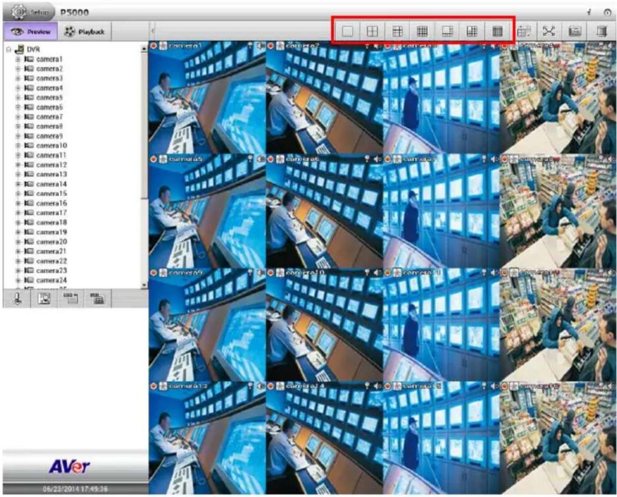
3.5 Enable/Disable the Sound of the Channel
User can click the audio icon (to mute () the sound of channel. Click audio icon ()

again to turn on the sound.
3.6 Switching Multiple Screen to Single Screen Display
In multiple screen display mode, user can double-click on the channel screen to switch to single display screen mode. Double-clicking again on channel screen, the screen display will switch back to multiple screen display mode.
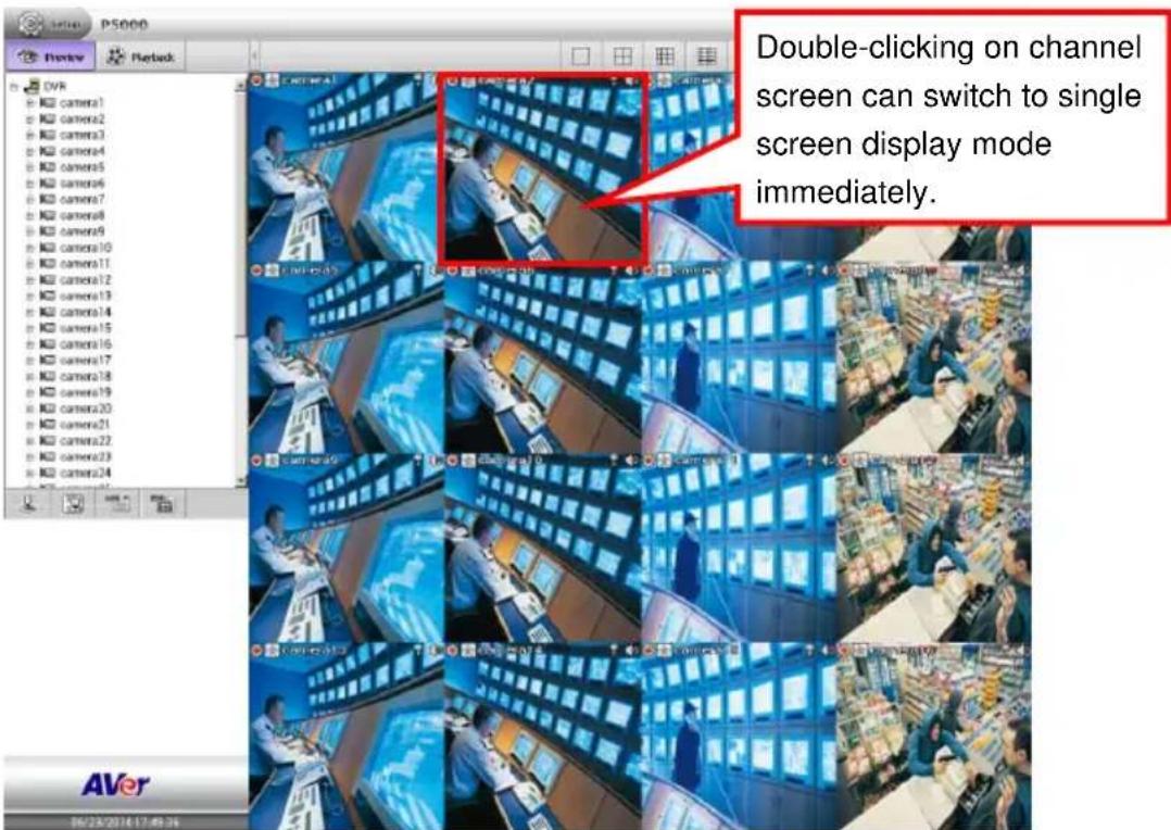
3.7 Viewing Emap
Click Emap( ) to call out the Emap dialog box. Click icon on E-map dialog box to expand the E-map dialog box on the preview screen. When alarm occurred, the icons on the map will turn to flash status. Click Map #(ex: Map 2) can switch to the selected map.
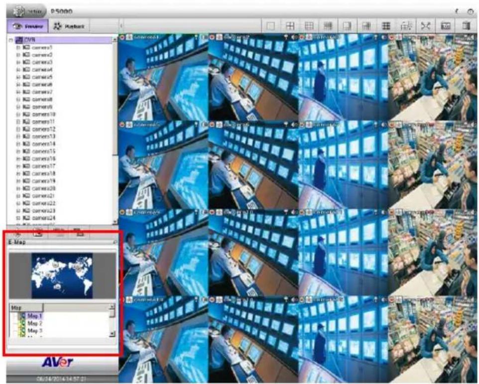
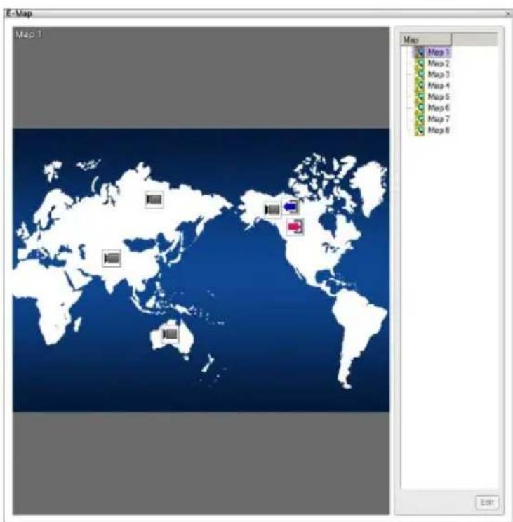
3.8 Snapshot the Screen
Taking a quick capture of current display screen and save in *.jpg format to external USB pen drive.
- Plug in the USB pen drive to USB port of NVR/DVR unit.
- In preview mode, Click the snapshot icon () and the snapshot dialog box is appeared.
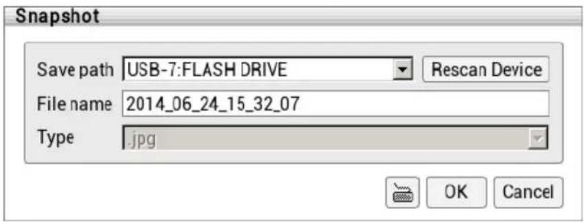
-
User can rename the File name by using virtual keyboard.
-
Click OK button to save the captured image file to USB pen drive.
-
The captured screen is looks like the figure below. There have date and time shown on the screen snapshot file.
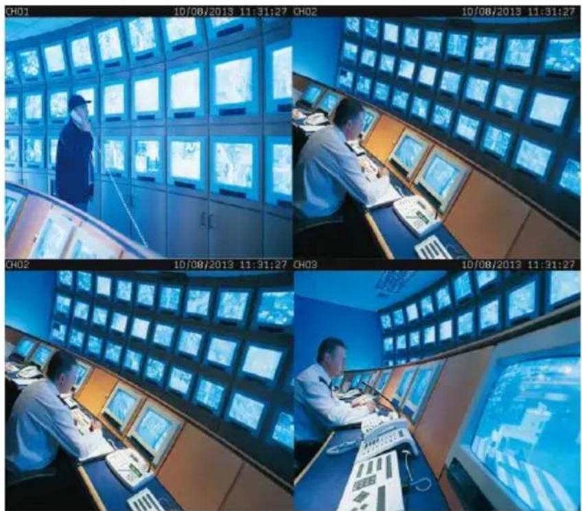
3.9 Full Screen Display
View the surveillance screen in full screen display mode.
In preview mode, click full screen icon ( ) to switch to full screen display. Click full screen icon ( ) on the bottom of right corner to return back to normal display mode.
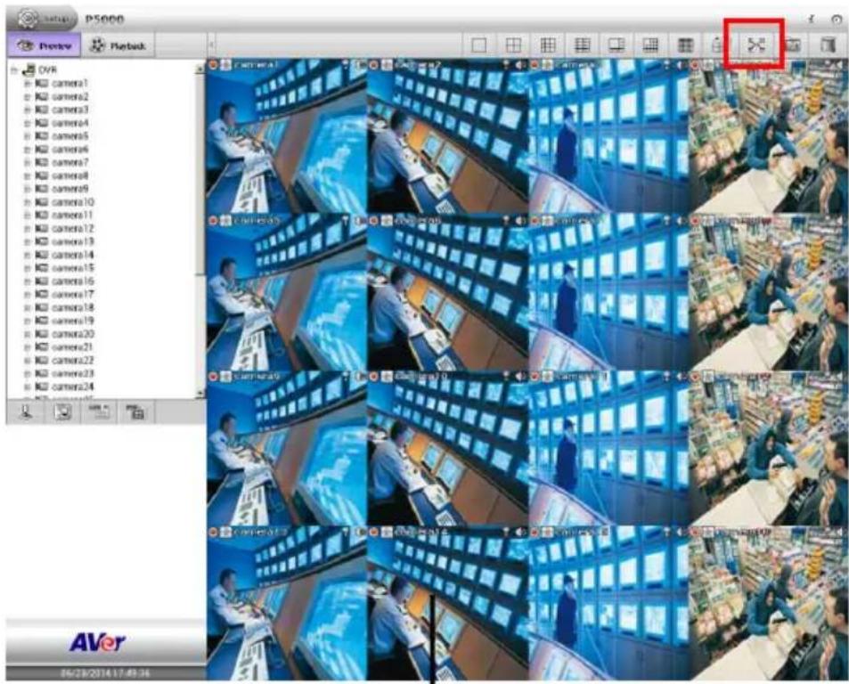
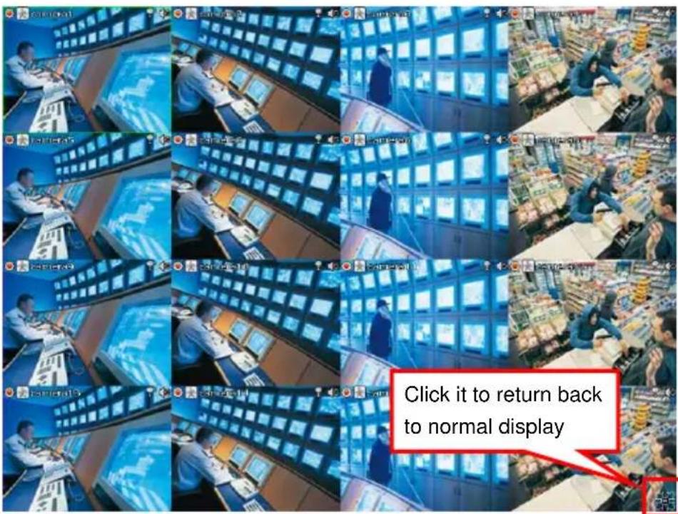
3.10 Hiding Camera List
User can hide the camera list to have larger view of surveillance screen.
In preview mode, click <icon and the camera list will be hided.
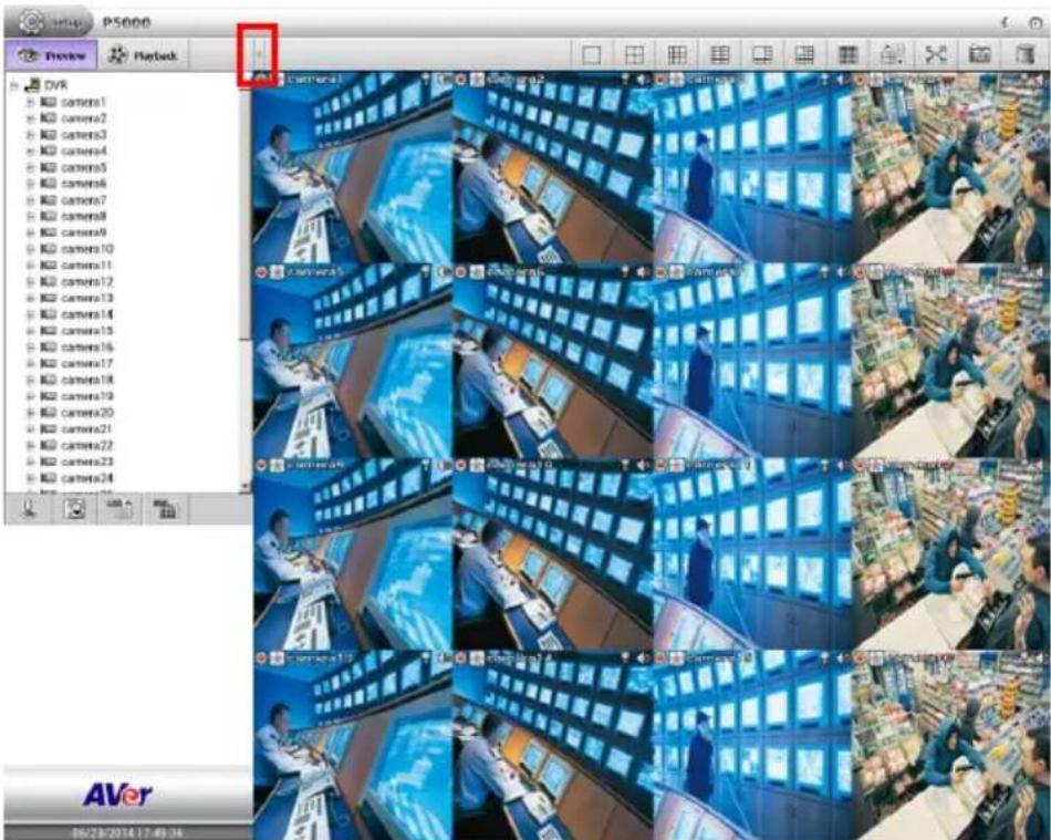
To show the camera list again, click > icon.
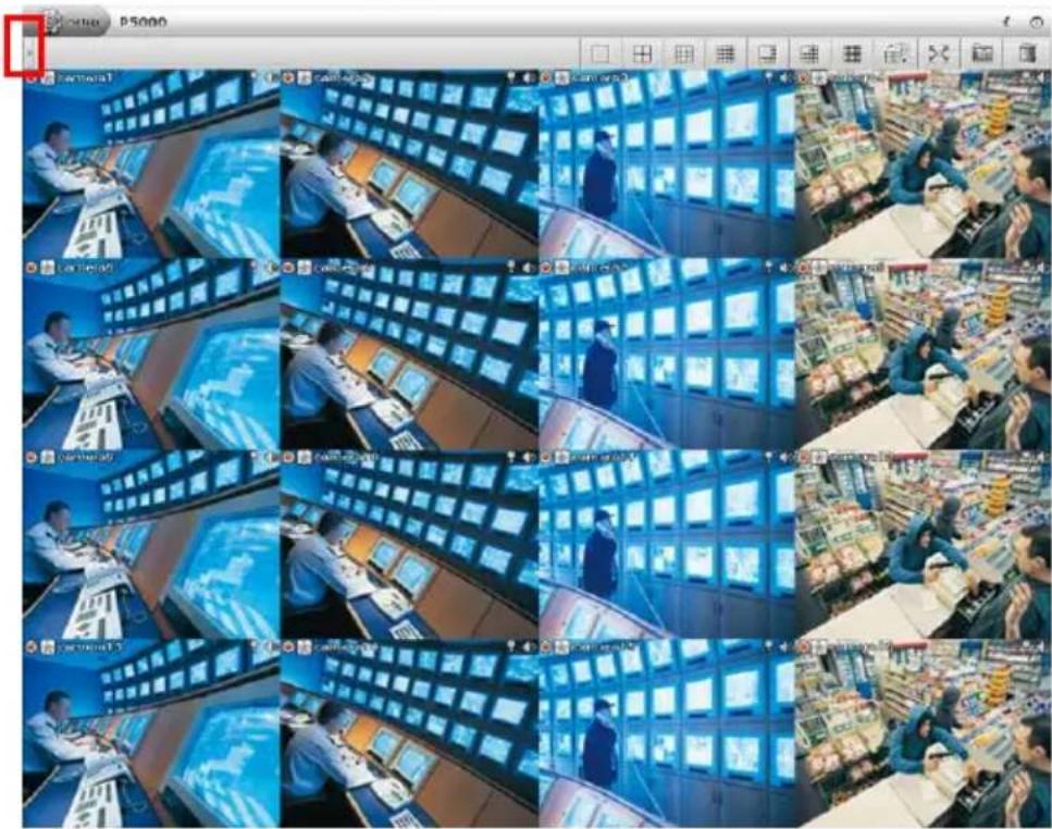
3.11 Auto Display Channel in Cycle
Click to start channel display in cycle automatically. To stop auto cycle display, click
again. If total channels are 36 channels and in 36-split screen display mode, the auto display cycle function won't work.
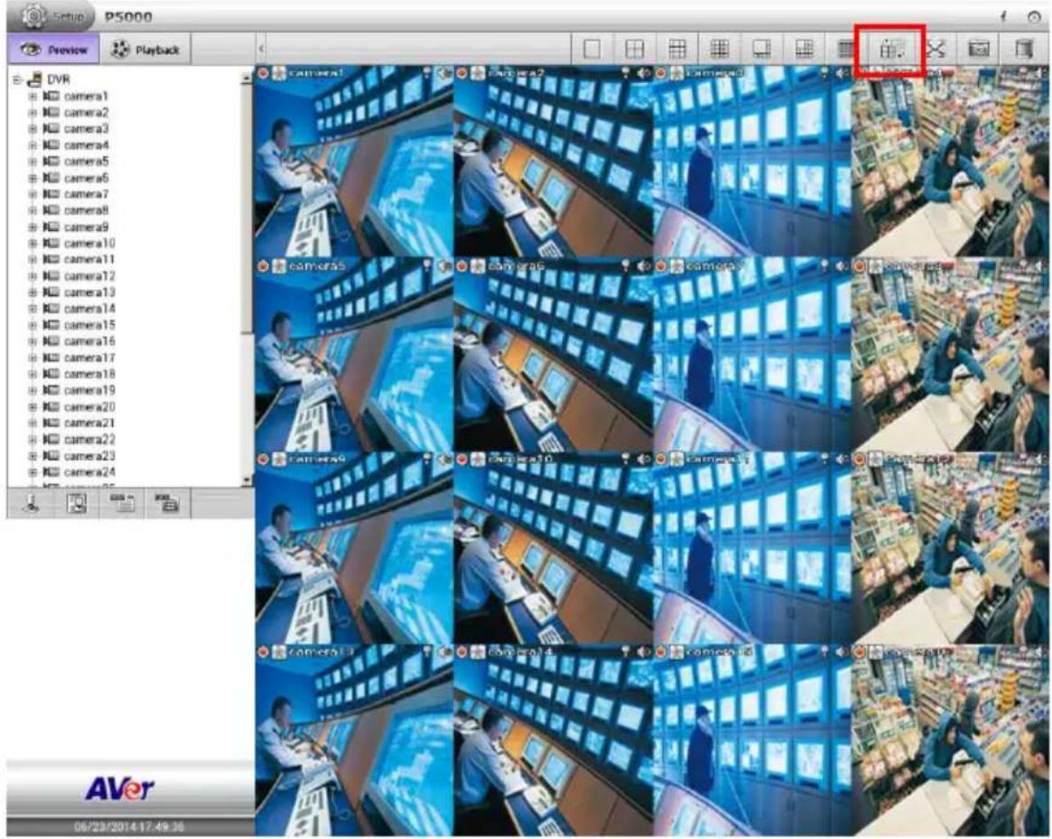
3.12 Enable/Disable 2-Way Audio Function
This function allows the NVR/DVR server site and IP camera site to talk via internet using microphone. Make sure your microphone and speakers work before using this function.
Click icon to enable 2-way audio function. To disable, click icon again.
Chapter 4 Playback Recorded Video on NVR/DVR System
In this chapter, it is going to description how to playback recorded video on NVR/DVR system in several ways and introduce some functions that user can operates in playback mode.
4.1 Playback on NVR/DVR System
User can playback the recorded video on NVR/DVR system instantly.
- Click Playback tab in preview mode to switch to playback mode.
- When switch to playback mode, the NVR/DVR system will start from backward 60 seconds recorded video to playback.
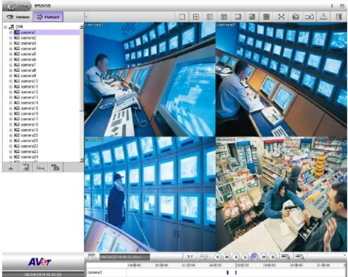
- The description of function buttons in playback mode refers to Chapter 3.3.
4.2 Playback the Specific Date/Time Period
User can select the specific date and time period to playback.
- In playback mode, click Calendar ( ) icon.
- In Calendar dialog box, select the date (date, month, year) that user wants to playback. The date in bold text indicates it has recorded data. Click and icon to switch the date or click ▼ icon next to month to select the month. To switch the year, click on the text of year and click spin button to select.
- In Time box, select the hour, minute, or second to setup the playback start up time. Click the hour and use spin button to adjust the hour. Using the same way to select the minute and second.
- After selecting the date and time, click OK to start playback.
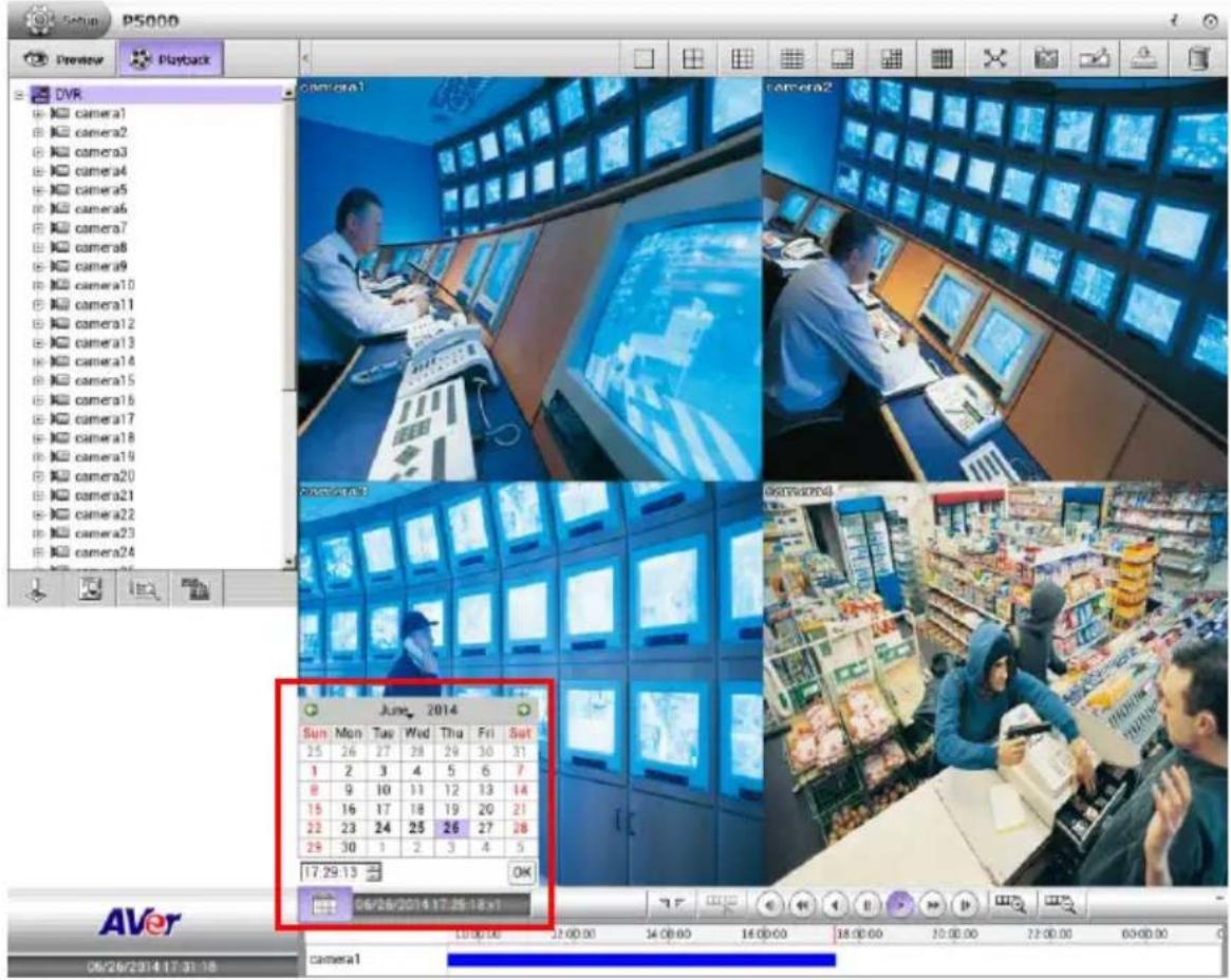
4.3 Using Event Search to Playback the Event
In playback mode, user can use Event Search to find the specific event to playback.
-
Select the channel that user wants to search. Click the channel on screen.
-
Click (Search) icon >> (Event Search) Then, the Event Search dialog box would appear at side area.
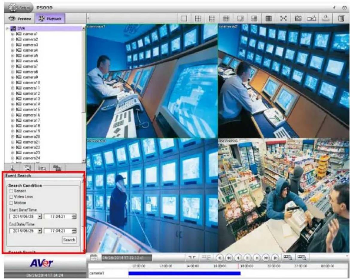
- In the Event Search dialog box, check the type of condition user wants to search. Then, set the Start Date/Time and End Date/Time.
-
Next, click OK to start searching.
-
When the Event list appears, click and select the item user wants to view; but not all the events can be playback such as Sensor.
- To close the Event Search dialog, click icon.
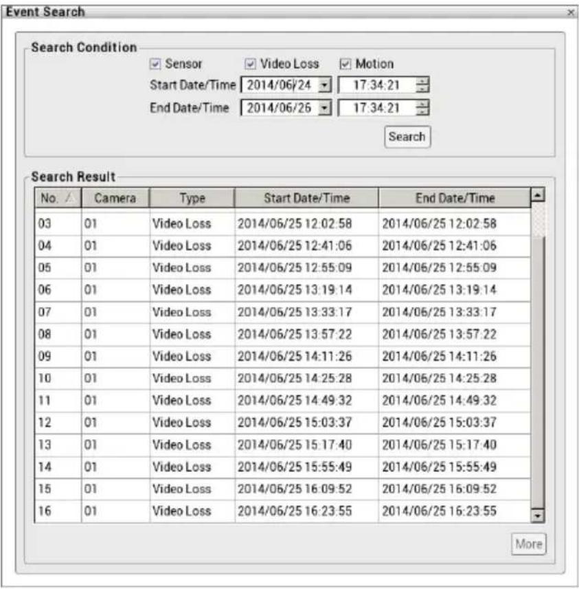
4.4 Using Visual Search to Playback the Specific Time
In playback mode, user can use Visual Search to find the specific time to playback.
- Click Search icon, then select Visual Search icon. The Visual Search dialog box would appear under the area.
- Select the channel that user wants to search. Click the channel on screen.
- In the Visual Search dialog, select the date. Click and icon to switch the month or click ▼ icon next to month to select the month. To switch the year, click on the text of year and click spin button to select.
- Then, click Search to start searching.
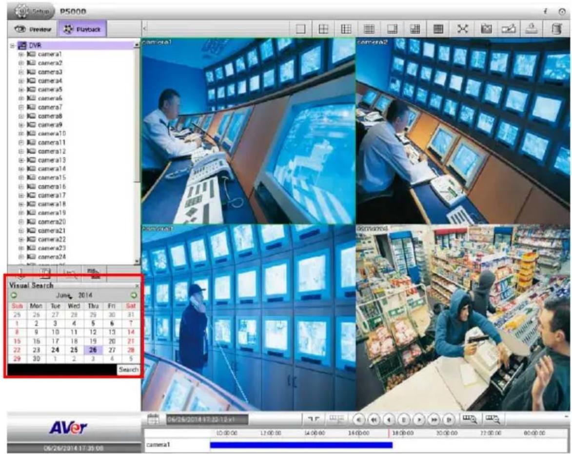
- When a series of frames appear by date, click on the frame to display another series of frames and search by every 2 hours of that date, every 8Minutes of that hour, and every 30seconds of that minute. Using → and ← to go to hour, minute, and second page.
- To playback the selected video, click button or double-click on selected video screen.
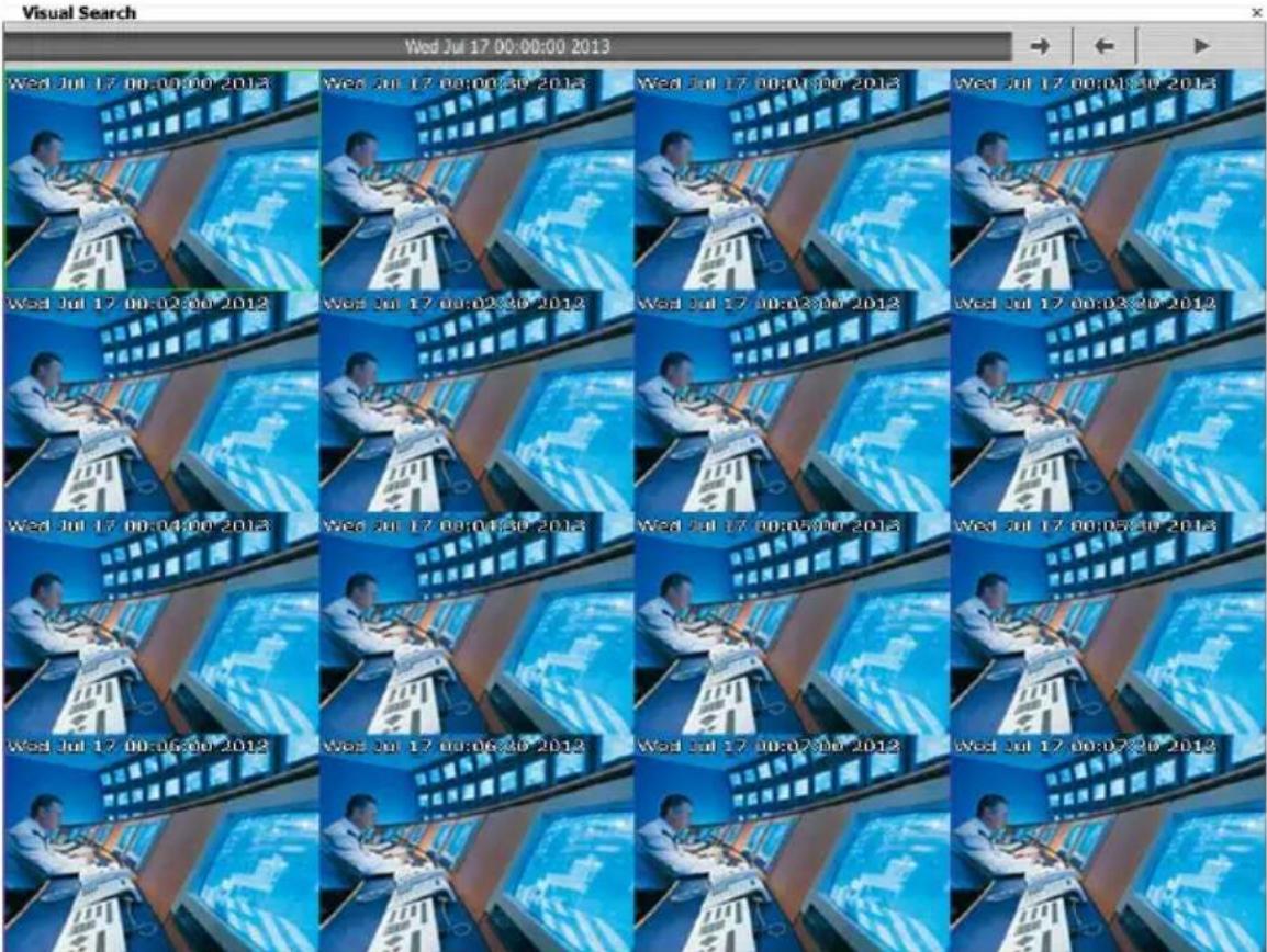
4.5 To Bookmark a Section of the Video for Playback
User can bookmark a specific time of video section.
- Using the mouse to move the playback time progress bar to the time that user wants to bookmark.

- Then, click icon. The Bookmark dialog box is appeared on the screen.
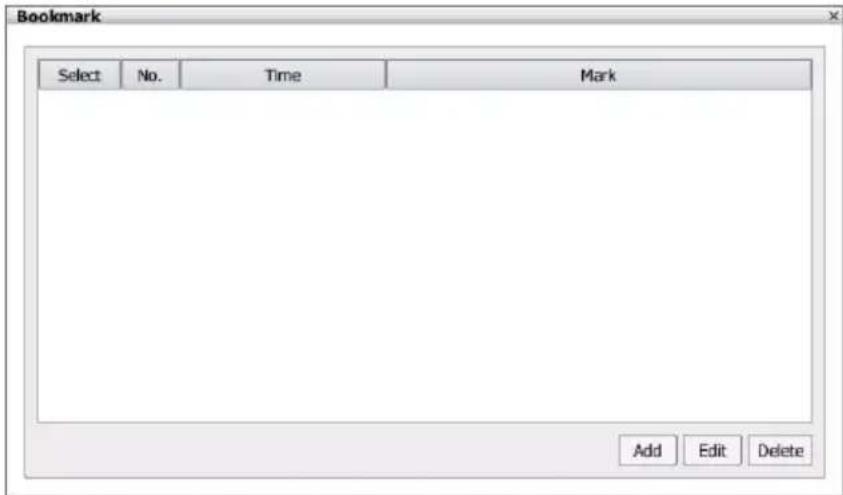
- Click Add button to create the new reference mark in the bookmark list. Enter a short description or name for the mark and click Apply button to save the bookmark. To exit bookmark Editor dialog box, click Cancel button. User also can select the File protect to prevent the bookmark file to be deleted.

When the bookmark is protected, the file won't be overwritten. If user wants to delete the bookmark, select the bookmark and click Edit. Un-mark the file protect option and click Apply. Then, the bookmark can be deleted it.
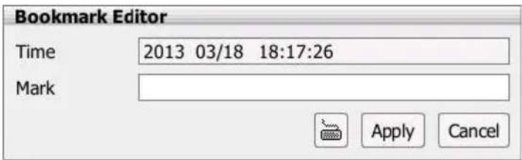
- Select and click one in the bookmark list to review the file.
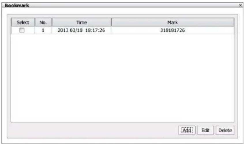
- To modify the bookmark, select the bookmark and click Edit button.
- To delete the bookmark, select the bookmark and click Delete button.
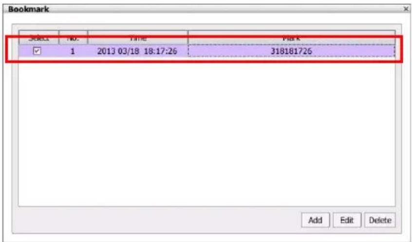
- To close the Bookmark dialog box, click icon.
4.6 Playback Mode Management
4.6.1 Managing Channel Display Position
User can arrange the channel display position that user is desired.
Select the camera in camera list section. Then, drag the camera to the channel that user wants to playback. Next, User should see the video playback on the channel screen.
The channels can be switched between each channel; just click the channel and drag the channel to the desire channel position. For example: Camera 01 switches to Camera 09; the Camera 01 will be Camera 09 position and the Camera 09 will switch to the Camera 01 position.
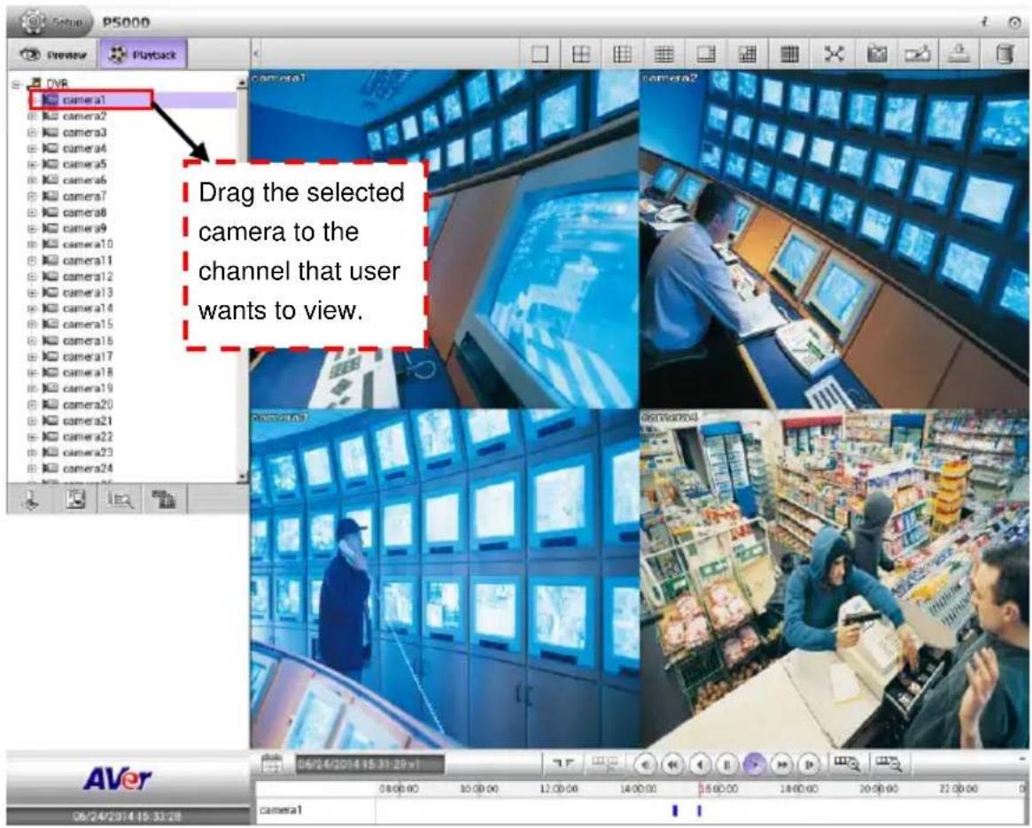
4.6.2 Enable/Disable Sound of the Channel
First, switch to single screen display mode. Then, Click the 📄 on the channel screen to disable the sound play. Click 🖼 again to enable sound play.
4.6.3 Switching Multiple Screen Display to Single Screen Display
In multiple screen playback mode, user can double-click on the channel screen to switch to single display screen mode. Double-click on channel screen again; the screen display will switch back to multiple screen playback mode.
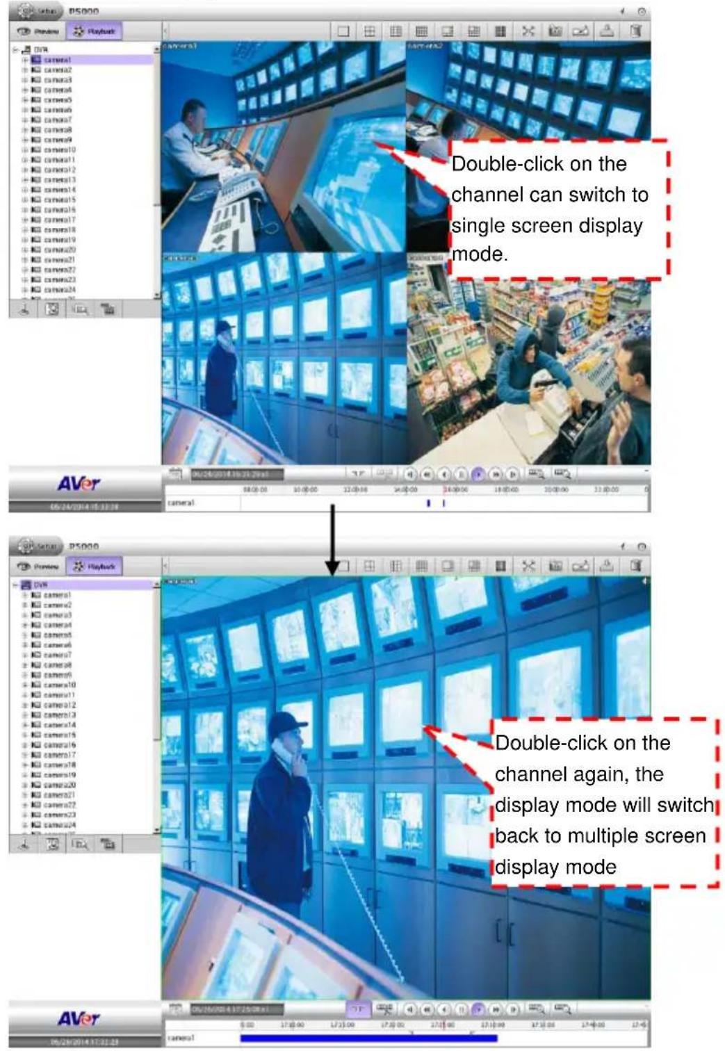
4.6.4 Full Screen Display
View the playback screen in full screen display mode.
In playback mode, click full screen icon ( ) to switch to full screen display. Click full screen icon ( ) on the bottom of right corner to return back to normal display mode
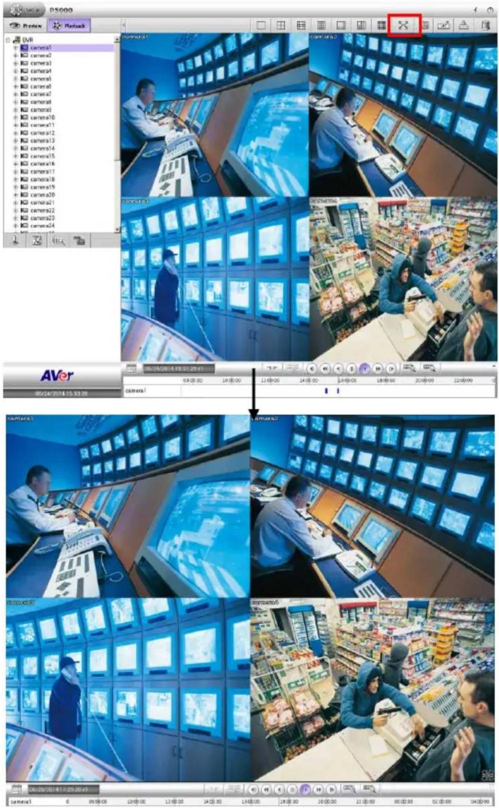
4.6.5 Hiding Camera List
User can hide the camera list to have larger view of surveillance screen.
In playback mode, click icon next to preview tab and the camera list will be hid. To show the camera list again, click icon.
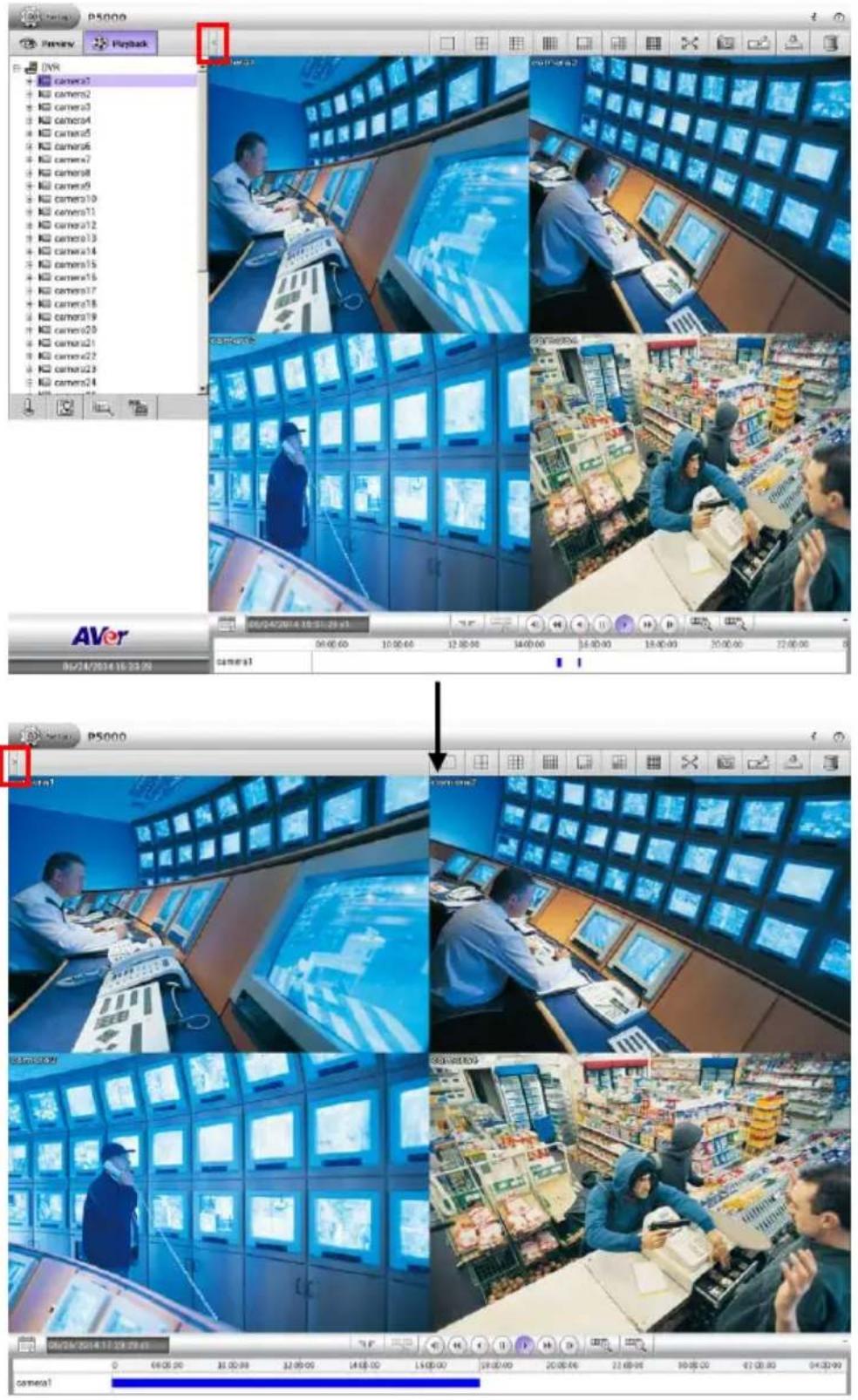
4.6.6 Output a Video Clip to a USB Pen Drive
- Switch the playback screen to 1 single screen display mode.
- Using 📄 and 🌐 button to expand the time bar for easy to set the segment period.
- Click (Segment) button to set the mark.
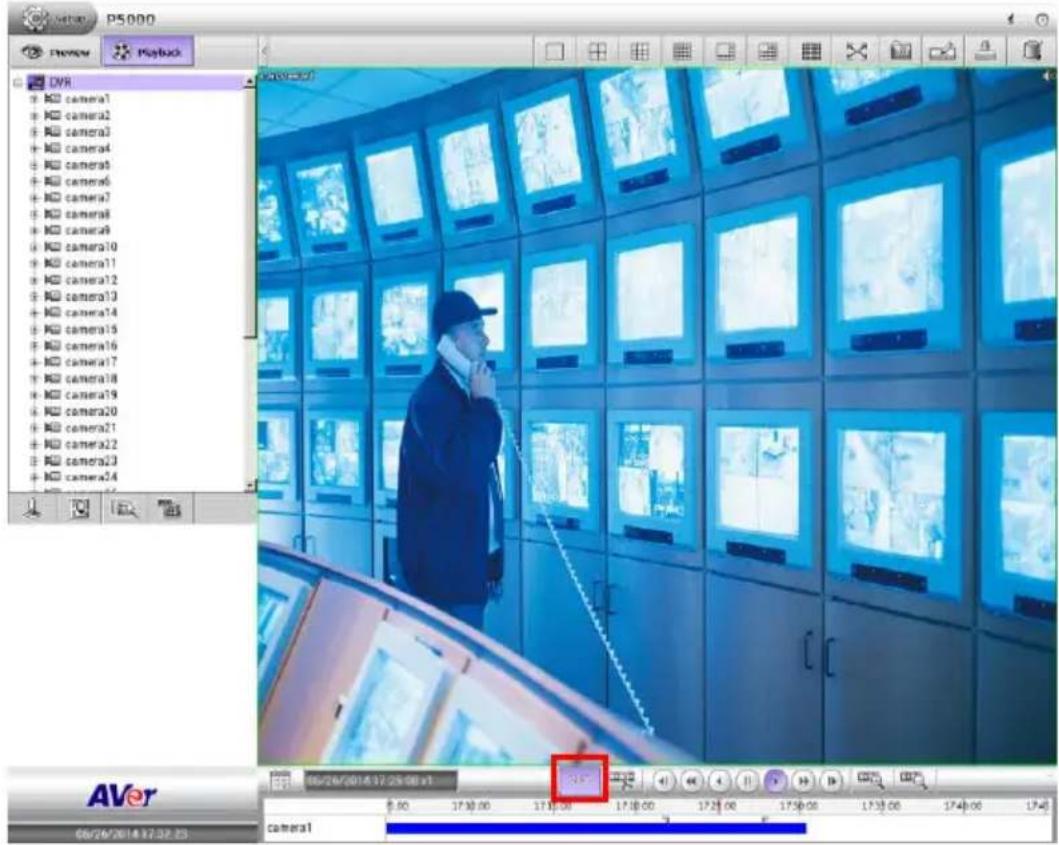
- Then, drag the ▼▼ mark (segment) to set video period portion. To cancel segmentation, click button (Segment) again.

- Click Output Video Clip button (☐) and the Output Video Clip dialog box is appeared.
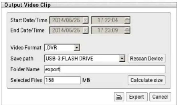
■ Start Date/Time: Displays the begin time and date of segment video file.
■ End Date/Time: Displays the end time and date of segment video file.
■ Video Format: Select the file format -- *.DVR or *.MP4.
- Save path: Where to save the segment video file. Click Rescan Device to detect the external USB pen drive if NVR/DVR system didn't detect it.
■ Folder Name: Give a name for segment video file. Using virtual keyboard to enter the name).
■ Calculate size: To calculate the file size of segment video file. The calculate result is displayed in Select File column.
■ Select Files: Displays the file size of segment video file.
-
Click Export button to save wanted segment portion.
-
To playback the export video clip, please refer to Chapter 5.
4.6.7 Snapshot the Screen View
- Select the channel or all channels.
- Plug the USB pen drive to NVR/DVR unit.
- Click Snapshot ( ) button.
- In Snapshot dialog box, check the Save path has been detected by NVR/DVR system. If the save path doesn't found, click Rescan Device button to re-detect it.
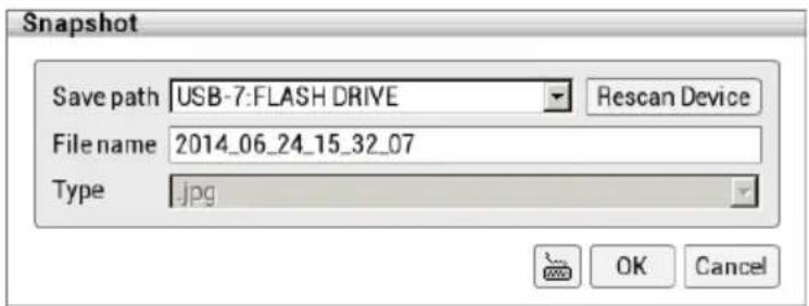
- If user wants to re-name the File name, call out the on-screen keyboard and enter the new file name in File name column.
- Click OK to capture and save the screen shot.
- The captured and saved screen image can be viewed on PC.
Chapter 5 Playback by Qplayer
You can playback the backup files by using QPlayer applications on the PC. When you back up the recorded file, QPlayer applications are automatically included in the backup folder if user has enabled the selection of Inculde player when backup when backup recorded file. With QPlayer, it is similar in Playback mode and supports different split screen types to view all the video at the same time.
To run the application, go to backup folder and select Qplayer folder, then, double-click Qplayer.exe.
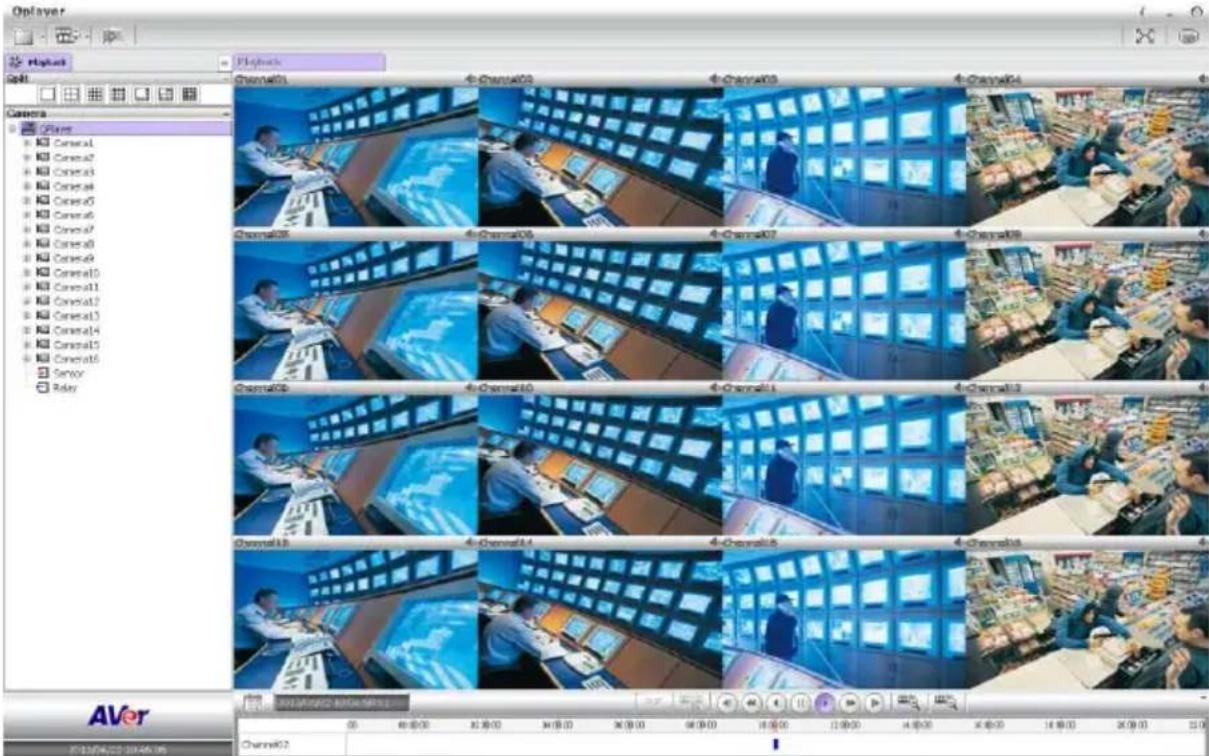
5.1 Familiarizing Functions of Qplayer
In Qplayer main UI, click File > Open File to located the backup file folder.

Please copy the whole backup folder under hard disk direction of PC (ex: C:).
The functions of Qplayer will be described in following:
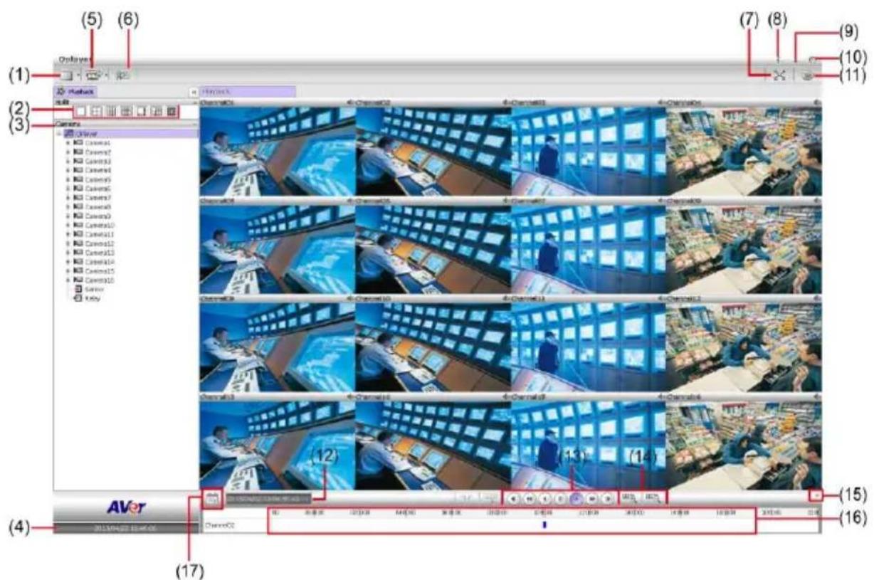
| Name | Function |
| (1) File | Click it to open the backup file. |
| (2) Split Screen Mode | Select from 7 kinds of split screen type to playback the recorded video file of all the camera, or one camera over the other or alongside on a single screen. |

To only display one of the video in the multiple-screen mode, double click on the video screen you only want to display.
| (3) Camera list | Lists all cameras. Click + to expand the list. User can select and drag the camera to desire channel location. |
| (4) Date and Time | It shows the current date and time. |
| Name | Function |
| (5) Export | Export function includes 2 functions – Snapshot and Print.-Snapshot:Catch a static current screen image and save it as a JPG file on local hard disk.-Print:Print out the current Qplayer screen. |
| (6) Bookmark | Mark a reference point when reviewing the recorded video file to which you may return for later reference (see also Chapter 5.1.1). |
| (7) Full screen | Use the entire area of the screen to only display the video. To return, press the right button of the mouse or ESC on the keyboard or click the arrow icon.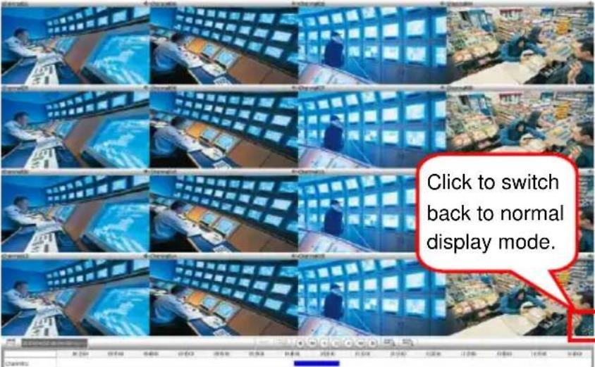 When you switch to full screen in multiple-screen mode, Left click to toggle to only display one of the video in the multiple-screen mode or all. When you switch to full screen in multiple-screen mode, Left click to toggle to only display one of the video in the multiple-screen mode or all. |
| (8) System Information | Click it to view NVR/DVR system's version and copyright.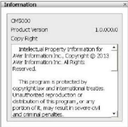 |
| (9) Minimize | To minimize the Qplayer on the task tray. |
| (10) Power button | Call up the Power dialog box.In the Power dialog box, user may do the following: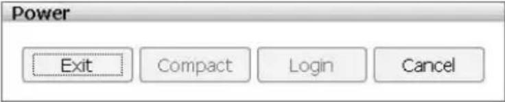 - Exit: To shutdown the NVR/DVR system.- Cancel: To exit Logout dialog box. - Exit: To shutdown the NVR/DVR system.- Cancel: To exit Logout dialog box. |
| (11) On Screen Keyboard | If the keyboard is not available, you may use the Virtual Keyboard.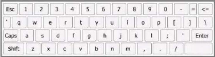 |
| (12) Status bar | Display the recorded date, time and play speed. |
| (13) Playback Control Buttons | From left to right order: 1/4x, or 1/8x. The playback speed will show on the screen. 1/4x, or 1/8x. The playback speed will show on the screen. 8x, 16x, 32x, or 64x. The playback speed will show on the screen. Next: Go to the next frame.End: Go to the end of the recorded video file. 8x, 16x, 32x, or 64x. The playback speed will show on the screen. Next: Go to the next frame.End: Go to the end of the recorded video file. |
| (14) Zoom in/Zoom out | To expand the playback time bar from an hour to minute. |
| (15) Close up progress bar | Click to close up the progress bar. Click again to open up. |
| (16) Progress bar | Show the progress of the file being played. You may move the bar to seek at any location of the track.Using the Zoom In/Out button to expand the playback time from an hour to minute. Meaning of color in progress bar:- Red: Alarm record- Green: Motion record- Blue: Always record(normal record)- Yellow: Video loss- White: No record date Meaning of color in progress bar:- Red: Alarm record- Green: Motion record- Blue: Always record(normal record)- Yellow: Video loss- White: No record date |
| (17) Calendar | Select the date on the calendar and the time to where to start playing the recorded video file. Click OK to start playback.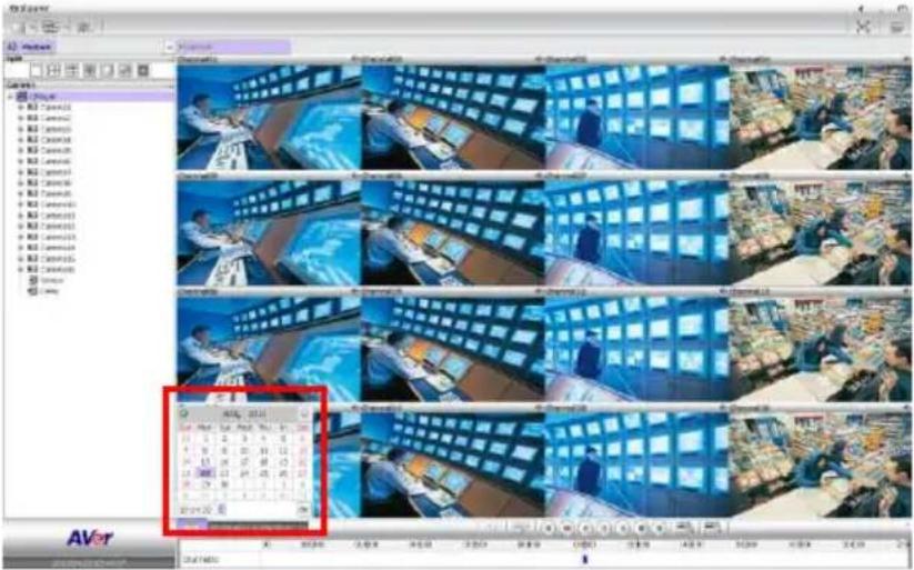 - Date: click the date on calendar to select. The date in blod text indicates there has recorded file. Click and icon to switch the date or click ▼ icon next to month to select the month. To switch the year, click on the text of year and click spin button to select.- Time: In Time box, select the hour, minute, and second to setup the playback start up time. - Date: click the date on calendar to select. The date in blod text indicates there has recorded file. Click and icon to switch the date or click ▼ icon next to month to select the month. To switch the year, click on the text of year and click spin button to select.- Time: In Time box, select the hour, minute, and second to setup the playback start up time.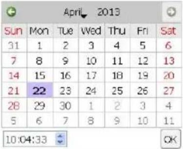 |
5.1.1 To Bookmark a Section of the Video for Playback
User can bookmark a specific time of video section.
- Using the mouse to move the playback time progress bar to the time that user wants to bookmark.

- Then, click icon. The Bookmark dialog box is appeared on the screen.
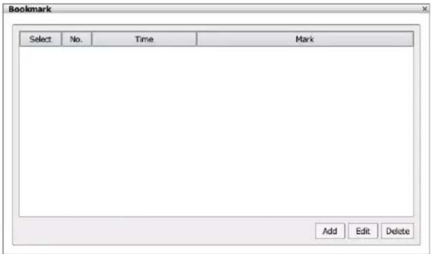
- Click Add button to create the new reference mark in the bookmark list. Enter a short description or name for the mark and click Apply button to save the bookmark. To exit bookmark Editor dialog box, click Cancel button.
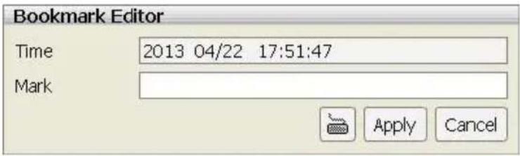
- Select and click one in the bookmark list to review the file.
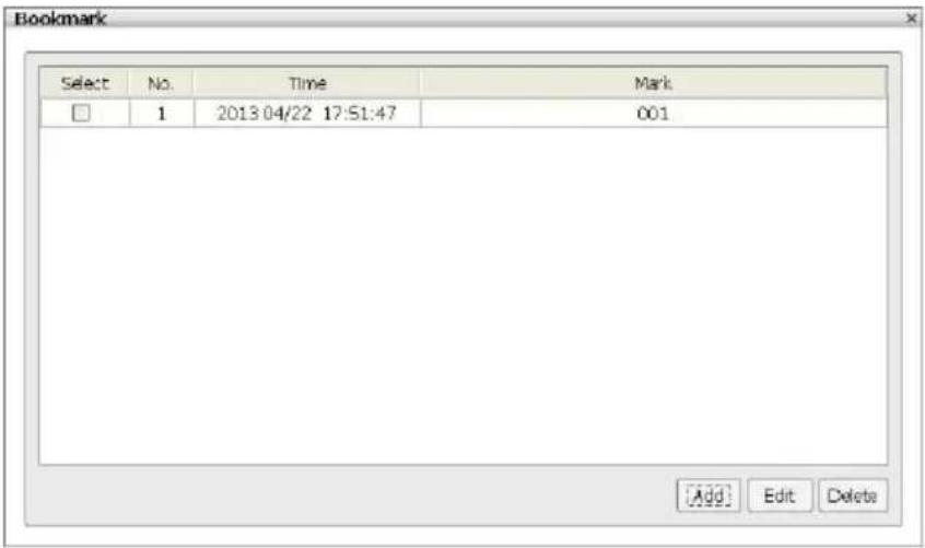
- To modify the bookmark, select the bookmark and click Edit button.
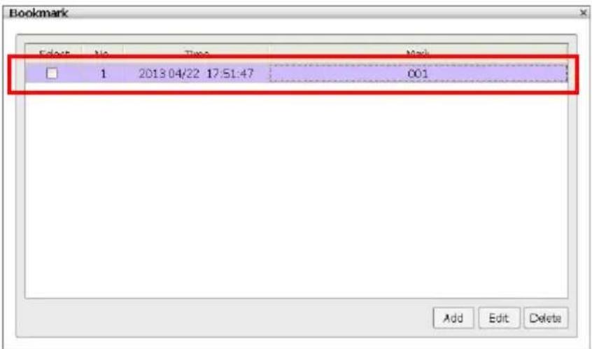
- To delete the bookmark, mark the bookmark and click Delete button.
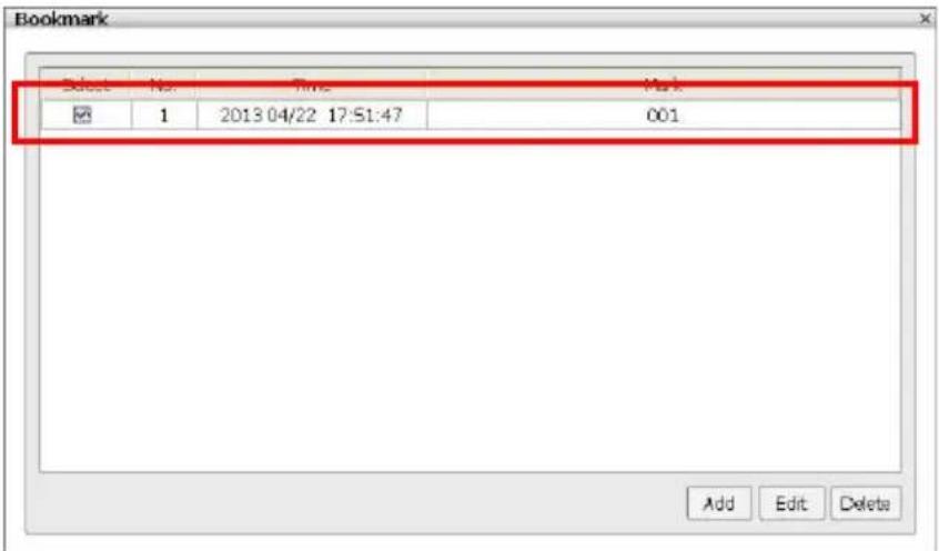
- To close the Bookmark dialog box, click icon.
Chapter 6 Using the PCViewer
User can use Microsoft Internet Explorer to access NVR/DVR system by entering the IP address. To use this feature, make sure that your PC and NVR/DVR server both are connected to the internet and the Network feature is enabled.
Accessing this feature for the first time you will be prompted by your browser to install PCViewX.cab, allow the installation and you should be able to connect and login afterwards. Click Install when the Internet Explorer - Security Warning dialog box appears.
After installing the PCViewX.cab and when connecting to the NVR/DVR system, you are required to enter account ID (default is admin) and password (default is admin) and select the type of network. Admin account has the authority to remote setup the NVR/DVR system configuration on PCViewer.
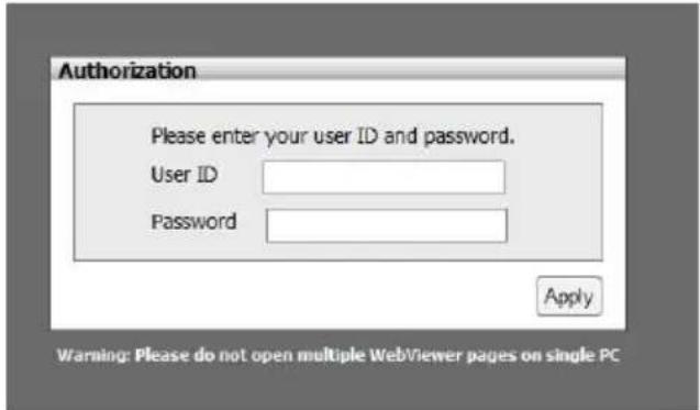
[Note]
- PCViewer supports on Windows 7(IE9, IE10, IE11) and Windows 8(IE10 & IE11).
- One PC/NB only can operate one PCViewer application.
- PCViewer doesn't support the IE browser of Windows 8 metro version.
6.1 Familiarizing Functions of PCViewer
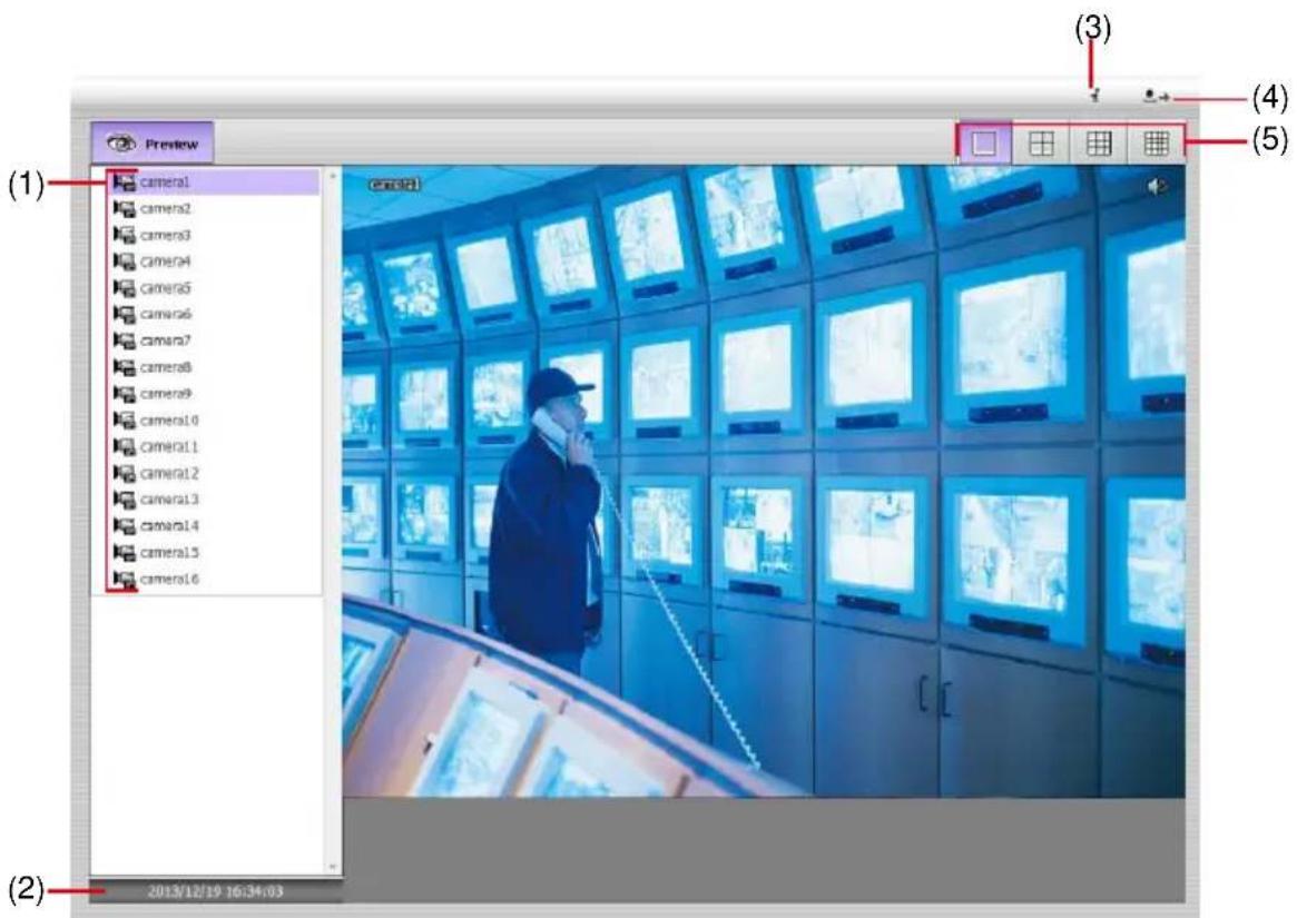
| Name | Function |
| (1) Camera list | Lists all cameras. Click the camera # to view in single screen display mode or click camera group to view in multi-screen display mode. |
| (2) Date and Time | It shows the current date and time. |
| (3) Information | Click it to view NVR/DVR server's model name, S/W version and PCViewer FW version. |
| (4) Logout | To exit the application. |
| (5) Split Screen Mode | Select from 4 kinds of split screen type to view live video of remote NVR/DVR server. |
Appendix USB Recovery
Save the firmware on USB pen drive and through the USB port on NVR/DVR unit to recovery the firmware of NVR/DVR system. All the configuration will be erased after recovery process.
- Download the firmware from website http://surveillance.aver.com/ >> Support >> download Center.
- After download the firmware file, un-zip the file and save on USB pen drive.
[Note] Copy the entire firmware file folder into USB pen drive. - Power off the NVR/DVR system.
- Plug the USB pen drive that contains recovery firmware into USB port that is located in front of NVR/DVR unit (upper one).
- Then, power on NVR/DVR unit. While the NVR/DVR is reading file, the screen is black. Please wait for a System Recovery Procedure window to show up.
- When System Recovery Procedure window show up, click Yes to continue it. If user wants to cancel the firmware upgrade procedure, click No.
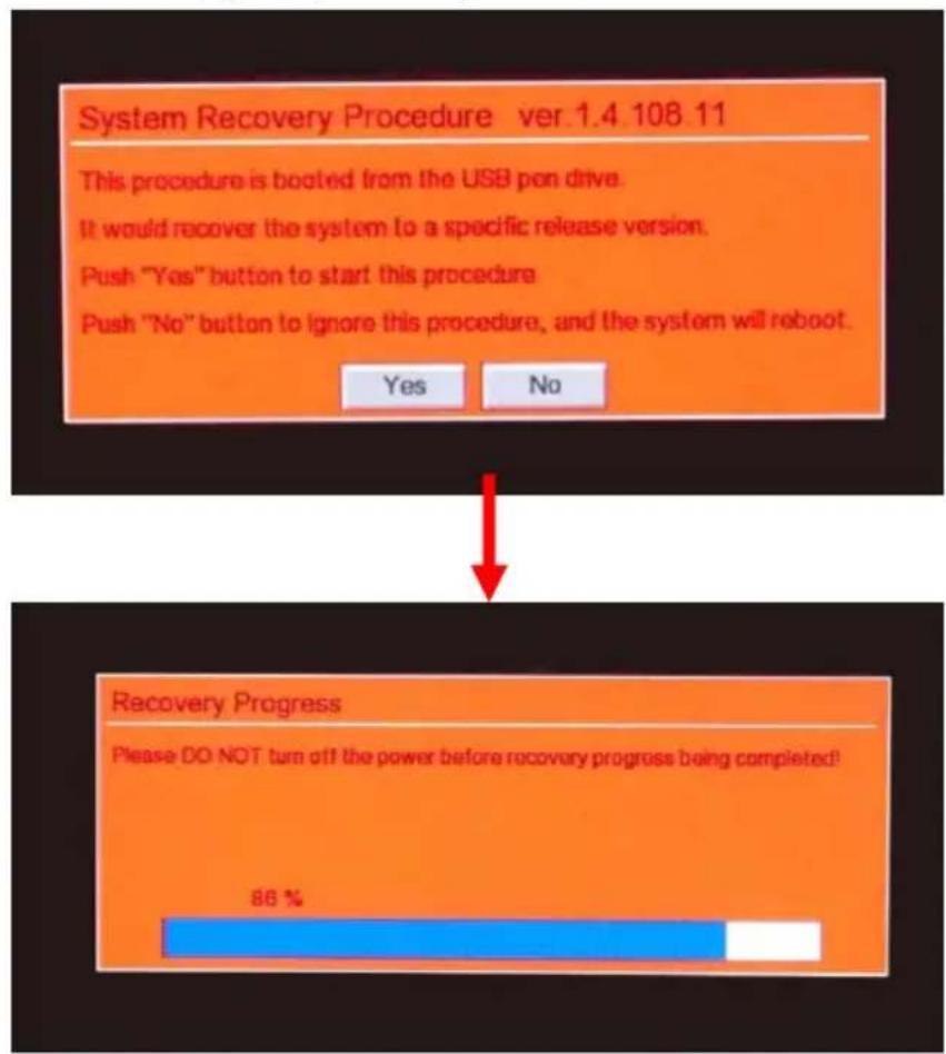
- After all procedures have completed, the Reboot window is show up. Remove the USB pen drive from NVR/DVR unit and click Reboot button to restart NVR/DVR system.
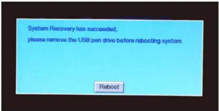
WARRANTY NOTICE
LIMITED WARRANTY
AVer Information, Inc. warrants this product to be free of defects resulting from faulty manufacture or components under the following terms:
WARRANTY LENGTH
Labor is warranted for (3) three year from the date of purchase.
Parts are warranted for (2) two year from the date of purchase.
Replacement products will be warranted for the remainder of the one year warranty period or (30) thirty days, whichever is longer
WHO IS PROTECTED
This warranty is enforceable only by the first consumer purchaser
WHAT IS AND IS NOT COVERED
Except as specified below, this warranty covers all defects resulting from faulty manufacturing of this product. The following are not covered by the warranty.
- Any product on which the serial number has been defaced, modified, or removed
- Damage, deterioration, or malfunction resulting from:
Accident, abuse, misuse, neglect, fire, water, lightning, or other acts of nature, commercial or industrial use, unauthorized product modification, or failure to follow instructions included with the product.
Misapplication of service by someone other than the manufacturer's representative Any shipment damages (Claims must be made with carrier)
Any other cause which does not relate to a product defect
- Cartons, cases, batteries, cabinets, tapes, or accessories used with product
- AVer Information Inc. does not warrant that this product will meet your requirements; it is your responsibility to determine the suitability of this product for your purpose
WHAT WE WILL AND WILL NOT PAY FOR
We will pay labor and material expenses for covered items. However, we will not pay for the following:
- Removal or installation charges
- Shipping charges
- Any incidental charges
EXCLUSION OF DAMAGES
THE MANUFACTURER'S SOLE OBLIGATION AND LIABILITY UNDER THIS WARRANTY IS LIMITED TO THE REPAIR OR REPLACEMENT OF A DEFECTIVE PRODUCT AT OUR OPTION. THE MANUFACTURER SHALL NOT, IN ANY EVENT, BE LIABLE TO THE PURCHASER OR ANY THIRD PARTY FOR ANY INCIDENTAL OR CONSEQUENTIAL DAMAGE (INCLUDING, BUT NOT LIMITED TO, DAMAGES RESULTING FROM INTERRUPTION OF SERVICE AND LOSS OF BUSINESS) OR LIABILITY IN TORT RELATING TO THIS PRODUCT OR RESULTING FROM ITS USE OR POSSESSION.
LIMITATIONS OF IMPLIED WARRANTIES
There are no other oral or written warranties, expressed or implied, including but not limited to those of merchantability or fitness for a particular purpose. Any implied warranties are limited in duration to one year from the date of purchase
STATE LAW AND YOUR WARRANTY
This warranty gives you specific legal rights, and you may also have other rights granted under state law. These rights vary from state to state
CONTACT INFORMATION
Taiwan & International
No. 157, DA-An Rd., Tucheng Dist., New Taipei City, Taiwan
TEL: 886-2-2269-8535
Web Site: http://www.aver.com/
- Federal Communications Commission Statement
- Class A ITE
- European Community Compliance Statement (Class A)
- DISCLAIMER
- TRADEMARKS
- COPYRIGHT
- Battery Safety Information
- Contents
- CHAPTER 1 HARDWARE INTRODUCTION....1
- CHAPTER 2 MAIN SYSTEM CONFIGURATION ...... 11
- System Advanced Setting....30
- Update/Export/Import 34
- Reset to Factory Default....40
- Network Setting....41
- Storage Setting 46
- Camera Management 57
- Use Active IP Function 62
- Familiarizing Functions on PTZ Control Panel 85
- CHAPTER 3 MONITORING THE NVR/DVR....129
- CHAPTER 4 PLAYBACK RECORDED VIDEO ON NVR/DVR SYSTEM.....140
- CHAPTER 5 PLAYBACK BY QPLAYER....156
- CHAPTER 6 USING THE PCVIEWER....163
- APPENDIX USB RECOVERY 165
- WARRANTY NOTICE....167
- Chapter 1 Hardware Introduction
- Package Contents
- Front Panel
- Back Panel
- P5036-R
- Install Internal Hard Disk
- Pin Definition of Sensor/Relay/RS485 Port
- ■ RS485 Pin definition
- ■ Sensor Pin definition
- Chapter 2 Main System Configuration
- Getting Started
- Familiarizing Icons on Dialog Box
- Familiarizing Functions in Preview Mode
- Familiarizing Functions in Playback Mode
- Compact Mode
- Familiarizing Function in Preview Compact Mode
- Familiarizing Function in Playback Compact Mode
- System Setup
- General System Setting
- System Advanced Setting
- Daylight Saving Time Setting
- Customizing System Login Setting
- Customizing System Miscellaneous Setting
- Update/Export/Import
- Importing NVR/DVR System Configuration
- Exporting NVR/DVR System Configuration
- Upgrading NVR/DVR Firmware
- Upgrading IP Camera Module Patch
- Setup Dual Monitor
- Reset to Factory Default
- Network Setting
- Setup NVR/DVR Server Name
- Network Advanced Setting
- Setup Transmitting Camera
- Setup UPnP
- Setup Bandwidth Limit
- Setup Network Port
- Storage Setting
- Formatting Hard Disk
- Creating RAID Drive
- [Not]
- Setup Storage Path for Recording Data
- Setup Hard Disk and Event Log Recycle Time
- iSCSI Setting
- Camera Management
- Connect the Analog Camera
- Connect the IP Camera
- Use Active IP Function
- Camera Detail Configuration
- ■ Info
- ■ Basic
- ■ Preference
- Color Setting
- Advanced
- ■ Exposure
- Stream
- ROI
- ■ Smart Stream
- ■ Privacy Mask
- ■ Motion Detection
- ■ IVA
- Cross Detection
- Tampering
- Missing Object
- Suspicious Object
- ■ Sensor
- ■ Relay
- ■ PTZ Function
- Familiarizing Functions on PTZ Control Panel
- Record Management
- - Always Recording
- - Event Recording
- - Smart Recording
- - No Recording
- Alarm Schedule Setting
- Backup Setting
- Alarm Setting
- Setup Alarm Condition
- Setting Alarm Action
- - Relay Output
- - IP Camera Relay
- - Play Warning Sound
- - Send E-mail
- Mail Server
- ■ Snapshot
- - Upload File
- √ Upload Video Clip
- √ FTP Setting
- - PTZ preset point
- User Account Setting
- Creating an User Account
- Deleting an User Account
- I/O Setting
- Sensor Setting
- Relay Setting
- Emap Setting
- Setting Emap
- iPOS Setting
- Log Viewer
- Using the Event Log Viewer
- Using the Alarm Log Viewer
- Viewing Alarm Event
- Searching Alarm Event Logs
- Using POS Log Viewer
- NVR/DVR System Tools
- Hard Disk Calculator
- Using On Screen Keyboard
- Chapter 3 Monitoring the NVR/DVR
- Managing Camera Channels
- Meaning of Icons and Figures
- Enable/Disable the Camera Channel
- Changing Screen Channel Display Mode
- Enable/Disable the Sound of the Channel
- Switching Multiple Screen to Single Screen Display
- Viewing Emap
- Snapshot the Screen
- Full Screen Display
- Hiding Camera List
- Auto Display Channel in Cycle
- Enable/Disable 2-Way Audio Function
- Chapter 4 Playback Recorded Video on NVR/DVR System
- Playback on NVR/DVR System
- Playback the Specific Date/Time Period
- Using Event Search to Playback the Event
- Using Visual Search to Playback the Specific Time
- To Bookmark a Section of the Video for Playback
- Playback Mode Management
- Managing Channel Display Position
- Enable/Disable Sound of the Channel
- Switching Multiple Screen Display to Single Screen Display
- Full Screen Display
- Hiding Camera List
- Output a Video Clip to a USB Pen Drive
- Snapshot the Screen View
- Chapter 5 Playback by Qplayer
- Familiarizing Functions of Qplayer
- To Bookmark a Section of the Video for Playback
- Chapter 6 Using the PCViewer
- [Note]
- Familiarizing Functions of PCViewer
- Appendix USB Recovery
- WARRANTY NOTICE
- LIMITED WARRANTY
- WARRANTY LENGTH
- WHO IS PROTECTED
- WHAT IS AND IS NOT COVERED
- WHAT WE WILL AND WILL NOT PAY FOR
- EXCLUSION OF DAMAGES
- LIMITATIONS OF IMPLIED WARRANTIES
- STATE LAW AND YOUR WARRANTY
- CONTACT INFORMATION
Brand : AVer
Model : CM5000
Category : Security Camera