TDG310K1C - Uncategorized Platinum Tools - Free user manual and instructions
Find the device manual for free TDG310K1C Platinum Tools in PDF.

| Product Type | Tone Generator and Probe Kit |
| Brand | Platinum Tools |
| Model | TDG310K1C |
| Application | Tracing and identifying wires in telecom, network, and low-voltage cabling |
| Generator Dimensions | 5.5 x 3.0 x 2.0 inches (approx.) |
| Probe Dimensions | 8.0 x 1.5 x 1.0 inches (approx.) |
| Total Weight | 0.5 lb (approx. 0.23 kg) including batteries |
| Power Supply | 9V battery (generator), 9V battery (probe) |
| Tone Modes | Four selectable tones (steady, warble, fast warble, alternating) |
| Continuity Test | Yes, with LED indicator and audible beep |
| Maximum Distance | Up to 5,000 ft (1.5 km) on typical cabling |
| Signal Type | Analog tone |
| Probe Sensitivity Adjustment | Rotary volume control |
| LED Flashlight | Built-in flashlight on probe |
| Connector Compatibility | Alligator clips, RJ11/RJ45 modular adapters included |
| Battery Life | Approximately 40 hours continuous use (generator), 30 hours (probe) |
| Operating Temperature | 32°F to 122°F (0°C to 50°C) |
| Storage Temperature | 14°F to 140°F (-10°C to 60°C) |
| Maintenance | Clean exterior with a dry, lint-free cloth. Remove batteries if not in use for extended periods. |
| Safety Warnings | Do not use on live circuits. Not for use on energized lines above 48V. |
| Spare Parts & Repairability | No user-serviceable parts. Contact Platinum Tools for service or replacement. |
| Included Accessories | Tone generator, probe, RJ11/RJ45 adapters, alligator clips, carrying case, user manual |
| Certifications | CE, RoHS |
| Warranty | Limited lifetime warranty |
Frequently Asked Questions - TDG310K1C Platinum Tools
User questions about TDG310K1C Platinum Tools
0 question about this device. Answer the ones you know or ask your own.
Ask a new question about this device
Download the instructions for your Uncategorized in PDF format for free! Find your manual TDG310K1C - Platinum Tools and take your electronic device back in hand. On this page are published all the documents necessary for the use of your device. TDG310K1C by Platinum Tools.
USER MANUAL TDG310K1C Platinum Tools
TDG310 Digital Tone and Probe Kit User Manual
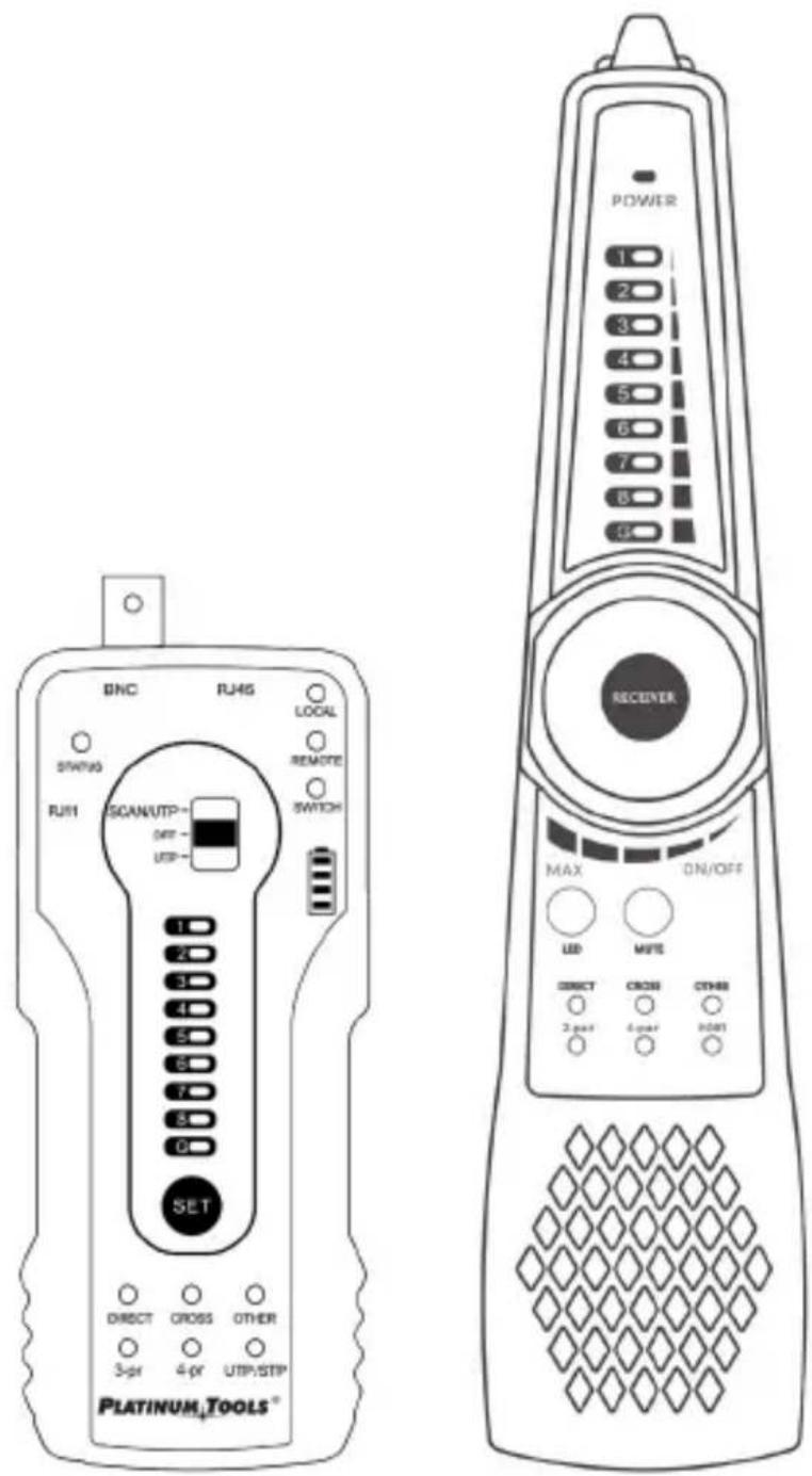
Table of Contents
Contents
Safety Information 4
General Warnings 4
Features and Benefits....5
Interfaces and Functions 6
Tone Generator....6
Digital Probe......8
Operating Instructions ....10
Setup 10
-
General Cable Tracing....10
-
Bundled cables....11
-
LED Signal Strength Indicators 11
-
Mapping Unknown Cables, Cable Faults and Wire Map Indicators .11
-
Connector Wiring and Short Circuit Detection ..... 12
-
2-Pair/4-Pair Indicator 12
-
A Break in the Wire....12
-
Use with PoE switches....12
Wire Map Detection....12
Cable Configuration Detection....12
Network Cable Port Continuity Detection 13
Short circuit test....14
Continuity Detection with Cables Connected to a Switch 15
PD (Powered Device) Emulation....15
Other Features ....16
Specifications....17
SAFETY INFORMATION
- This product is intended for use in compliance with the local electrical safety rules and should not be used where electrical sparks may be exposed to flammable or explosive gases (gas stations, hospitals, etc.).
- Use this product within operating temperature specifications.
- This product is only intended for low voltage testing up to 60 Volts. Do not use this instrument for high voltage circuits. Doing so may damage the instrument or cause injury or death.
GENERAL WARNINGS
- To retain functional integrity, keep this product dry and do not store it in humid environments when not in use.
- Remove batteries when not in use for extended periods to prevent corrosion.
- Do not expose the contacts of the connectors to moisture or dust.
- Impacts, collisions and vibrations may cause damage to internal components during transportation or use.
- Avoid disassembling the instrument, as no component inside can be repaired by the user.
- This instrument is not intended to be used in environments with strong electromagnetic interference.
FEATURES AND BENEFITS
The TDG310 Digital Tone and Probe Kit allows tracing and locating of single cables or bundles that are connected to unpowered or active networks such as phone lines, network cables or coax cables. The built-in test functions can verify proper network termination or test for shorts in the single-ended test mode. The tone generator can also determine the status modes of analog telephone lines.
Features
- Trace and locate cables in unpowered or live circuits.
- Includes audible and visual strength indicators.
• Built-in testing capacity for RJ45 termination. - Equipped to test PoE ports for power and speed configurations.
- Checks status of analog phone lines.
- Comes with a built-in high-intensity flashlight.
Benefits
- Digital tone generation and detection rejects extraneous analog noise to locate cables quickly and easily.
- Trace and test cables in the same interface.
- Identify cable types, including 2-pair or 4-pair, straight, cross or other.
- Cable scan and continuity testing for UTP, STP, RJ45, and RJ11 cables.
- Identify the status in the working telephone line: standby, ringing or off-hook.
- Quickly detect the near-end, mid-end and far-end cable faults.
- The RJ45 port withstands a maximum voltage of 60VDC and the wire can be traced directly to a powered PoE port.
- Perform continuity tests on shielded cable and shielding layers.
- PD powered detection detects whether the power output of the PoE switch is normal and detects the pins used for the power supply.
- Switch between Audible or Silent mode.
• Work in the dark with the built-in high-intensity LED flashlight.
Tone Generator
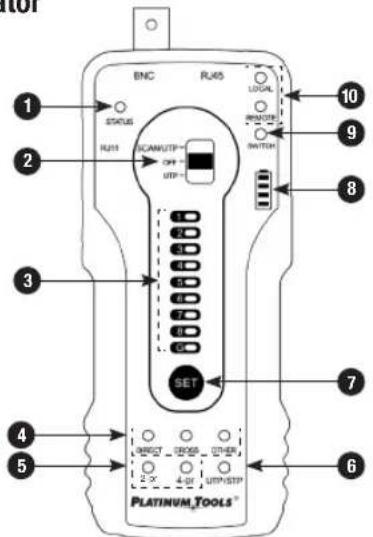
1 Telephone status indicator
2 Functions switch: SCAN/UTP, OFF, UTP cable test
3 Category cable sequence, continuity and cable shielding detection indicators
4 Category cable type indicators: straight, cross, other
5 2-pair / 4-pair indicator
6 Cable Shielding Indicator: Green-UTP (Unshielded), Red-STP (Shielded)
7 SET: Switches function between shielded and unshielded in cable tracer mode and local, remote or switch in UTP cable test mode
8 Battery strength indicator
9 SWITCH connection indicator
10 LOCAL/Remote connection indicators
INTERFACES AND FUNCTIONSINTERFACES A
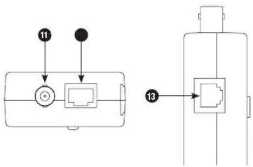
11 BNC interface
12 RJ45 cable port
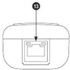
13 RJ11 port
Note: Please turn the tone generator OFF when testing the telephone line status. The STATUS indicator light flashing corresponds to telephone status (standby/ringing/off-hook).
Digital Probe
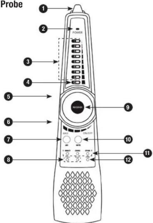
1 High-intensity LED Flashlight
2 Power Indicator
3 UTP Wire Map / Signal Strength Indicator
4 RJ45 Shield Indicator
5 Earphone Jack
6 RJ45 Test Port
7 LED Flashlight On/Off Switch
INTERFACES AND FUNCTIONSINTERFACES A
8 2-pair/4-pair Indicator
9 Switch/Sensitivity Knob
10 MUTE Button (long press for silent mode, short press for port connectivity detection)
11 RJ45 Cable Type Indicator: straight, cross or other
12 Port Continuity Detection Indicator (ON indicates local end cable connectivity function, OFF indicates cable sequence function)
13 PoE PD Powered Test Port (detects pin configuration of cable and PoE type)
Note: Probe port continuity detection only tests the local end. The tone generator can support near end, middle end and far end port detection.
OPERATING INSTRUCTIONS
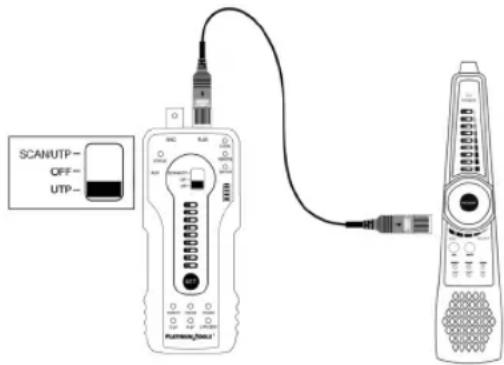
Setup
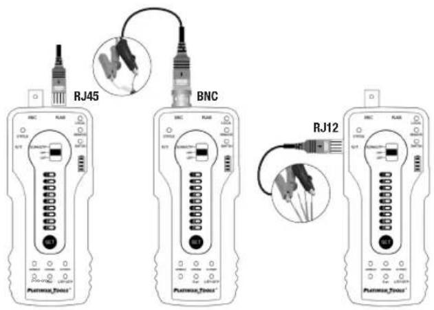
Check the connector for proper termination, then insert the network cable into the tone generator's RJ45 port, connect the BNC cable to the tone generator's BNC interface or connect the RJ11 telephone line to the RJ11 port. If the cable is not terminated, use the alligator cable to clip the bare copper wires of the cable.
1. General Cable Tracing
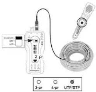
Switch the tone generator to the "SCAN/UTP" mode, then press the "SET" key to switch to UTP/STP mode. The color of the "UTP/STP" LED indicates the instrument's mode, with green for unshielded and red for shielded. Turn on and use the tone probe to trace the wire.
OPERATING INSTRUCTIONS
2. Bundled cables
The tone may bleed into the other cables of a cable bundle. Rotate the sensitivity knob of the probe to isolate and trace a specific cable if cables are closely routed or bundled.
3. LED Signal Strength Indicators
Press and hold the "MUTE" button for silent mode. In this mode, the signal strength indicator light is used to trace the wire. The stronger the signal, the more indicator lights are lit. Press "MUTE" again to exit the MUTE mode.
4. Mapping Unknown Cables, Cable Faults and Wire Map Indicators
To quickly locate or map the end of an unknown cable, insert one end of the cable in the RJ45 port in the tone generator, then insert the other end of the unknown cable to the RJ45 port in the tone probe. If the "Straight/ Cross/Other" LED lights, this is the other end of the unknown cable. The indicator also shows if there are cable faults. The 1-8 and G indicators show the wire map sequence by default, and the order in which the indicator lights up is the sequence of the line. When connected to the cable, the probe indicator the cable status
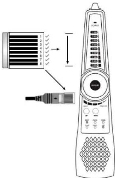
by sound: the "di" sound means connected pair lines, while the "du" sound means short circuit pair lines. All indicator lights of short circuit pairs are on at the same time.
OPERATING INSTRUCTIONS
5. Connector Wiring and Short Circuit Detection
Press the "MUTE" button on the probe: when the indicator light of the port is lit, the 1-8 and G indicator lights show that the connection between the cable wires and the connector is continuous. For a single-ended shorts test, insert one end of the network cable into the RJ45 port of the probe, then press "MUTE". If the "Port" LED is lit, there is a short circuit in the network cable.
6. 2-Pair/4-Pair Indicator
Connect the ends of the network cable to Switch and to the RJ45 port of the tone generator, then press the "SET" key to switch to the "SWITCH" mode. If the 1, 2, 3 and 6 indicators LEDs are lit, only 2 pairs in the cable or port are continuous. If all indicators 1-8 are lit, all 4 pairs of the cable or port are continuous.
7. A Break in the Wire
A tone that is not detected at the end of the cable may indicate a break in the wire(s). Trace the cable until the signal is not heard. This would indicate where the break is located. You may need to cut off the connector to trace the wires in a twisted pair cable individually with the alligator clip accessory.
8. Use with PoE switches
The RJ45 ports of tone generator and probe can withstand a maximum of 60VDC, the wire can be traced directly in connection with PoE switch.
Wire Map Detection
Cable Configuration Detection
Step 1: Insert the ends of the network cable into the RJ45 port of the tone generator and the RJ45 jack of the probe. Turn on the probe.
Step 2: Switch the tone generator to UTP mode. The 1-8 and G indicators will show the type of cable and the 2-pair or 4-pair indicators show the cable or port is continuous on wires 1, 2, 3 and 6 or wires 1-8.
Quickly determine the cable configuration through the tone generator or tone probe. If the Direct or Cross indicator is lit, the cable configuration is wired correctly according to TIA568A/B standards. Once the indicators
OPERATING INSTRUCTIONS
flash, the tone probe will beep to indicate the cable configuration. A single beep indicates a standard TIA568A/B configured cable, a double beep indicates a cross cable and a triple beep is a different or wrong configuration.
Network Cable Port Continuity Detection
In the UTP mode, press the "SET" key to switch to "LOCAL" mode.
Local Port (Near-End) Continuity Detection
When the "LOCAL" indicator LED is on, connect the other end of the network cable to the tone probe "UTP" port or disconnect the UTP port. The 1-8 and G lights indicate the near-end continuity status of network cable or ports within 1 meter of the tone generator.
In the picture shown, the 1st wire of the network cable port on the side of tone generator is disconnected.
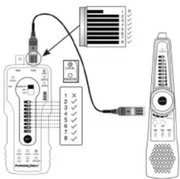
OPERATING INSTRUCTIONS
The 1st indicator light is off, indicating that the 1st wire of the port is not connected.
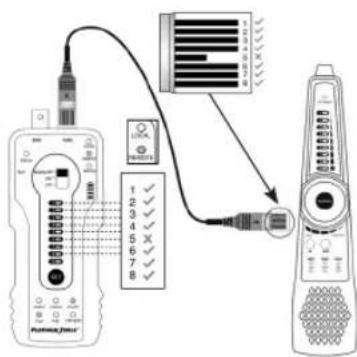
Remote (Far-End) Continuity Detection
While in UTP mode, press the "SET" key to switch to the "REMOTE" function. When the "REMOTE" indicator is lit, connect the other end of the cable to the UTP port of Probe. The REMOTE function in this case determines continuity faults within 1 meter of the probe.
The 1-8 and G LEDs indicate the continuity of the cable port connected to the probe.
In the picture shown, the 5th wire of the cable port on the side of the cable tracer (probe) is open, so the 5th indicator in the 1-8 indicators is off.
Mid-Span Cable Continuity Detection
If the cable sequence detects an break in both LOCAL and REMOTE modes, the break point of the cable is mid-span away from the ports on both sides.
Short circuit test
When the cable is connected to just the tone generator and in SWITCH mode, the indicator lights of the shortened pairs will flash. The same is true if the cable is connected to just the probe in PORT mode. If both are connected, the indicator lights of the short-circuited pairs on both devices will flash.
6 and 7 wires are short-circuited
14 15
OPERATING INSTRUCTIONS
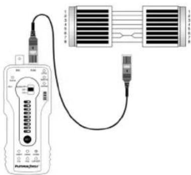
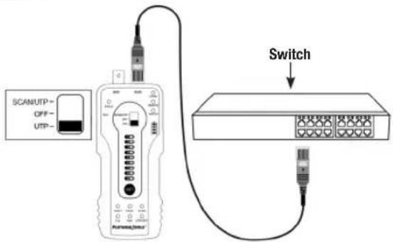
Continuity Detection with Cables Connected to a Switch
While in UTP mode, press the "SET" key to change to the "SWITCH" function. When connected to a switch, the 1-8 and G indicator lights show the continuity of the cable: lights on means connected, lights off means disconnected, with the 1, 2, 3 and 6 lines indicating a 100M switch and all lines 1-8 indicating a 1000M. This mode can also detect the short circuit status of network cables. Simply connect one end of the cable to the RJ45 port of tone generator and the other end to the switch, then check the indicator light.
PD (Powered Device) Emulation
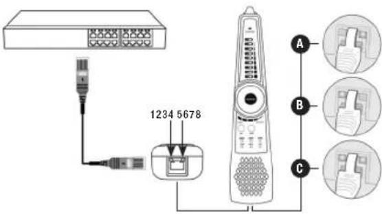
A Power detected on pairs 4/5 & 7/8
B Power detected on pairs 1/2 & 3/6
C Power detected on pairs 1/2, 3/6, 4/5, & 7/8
OPERATING INSTRUCTIONS SPECIFICATIONS
PD (Powered Device) Emulation
Connect a patch cable from the PoE switch or PSE power supply device to the "PD" port of the probe. If the indicator light is on, it means the port has been configured for PoE output and voltage is detected. There are 4 indicator lights on the "PD" port. When testing the pins used for power, if the 1, 2, 3 and 6 indicators are lit, the PoE port is supplying power through pairs 1/2 and 3/6. If the 4, 5, 7, and 8 indicators are lit, the PoE port is supplying power through pairs 4/5 and 7/8. If all indicators are lit, the PoE port is supplying through all four pairs 1/2, 3/6, 4/5 and 7/8.
This function is useful for checking the pins a PoE switch or other source is using to supply power, to avoid causing damage to a camera or other device.
Other Features
Line DC Level and Positive/Negative Polarity Testing
Using the BNC-to-Alligator clips cable, turn off the tone generator and clip the red and black wire clips to the telephone line or battery. Then, connect the cable to the BNC port of the tone generator. If the telephone cable is terminated with an RJ11 connector, connect the telephone cable to the RJ11 port instead.
If the indicator light is in green, that means the red wire clip is positive and the black clip is negative. If the indicator light is in red, the black is positive and the red is negative. The brightness of the indicator light also shows the level, with a brighter light indicating a higher level.
| Item Digital Tone Generator and Probe Kit | |
| Tone Generation Digital signal (rejects noise and false signals) | |
| Cable types RJ45 Twisted pair, RJ11 telephone line, BNC cable, etc. | |
| UTP cable test | LED wire map, shielded cable and shielding continuity indicator, check cable type indicator: straight/cross/other, 2-pair/4-pair continuity test, triple zone short testing, UTP cable short circuit test |
| Continuity test of RJ45 cable connectors | Detect the continuity of the pins on both sides of network cable and short circuits |
| PD (powered) test | PoE switch power supplying status test and check the pins used for power supply |
| LED lamp Short press | On/Off LED light |
| Silent mode | Long press “Mute” button to switch silent mode, find cable through LED strength indicators |
| Audio output Supports | external audio output and mono earphone jack |
| Power Supply | |
| External power supply | Four AA batteries |
| General | |
| Operating Voltage Up to 60VDC between pins | |
| Working Temperature | -10c — +50c |
| Working Humidity 30%-90% | |
| Dimension and Weight | |
| Tone generator | 152mm x 62mm x 27mm (6.0" x 2.4" x 1.1")0.12Kg (4.23 oz) |
| Probe | 218mm x 48mm x 32mm (8.6" x 1.9" x 1.3")0.1Kg (3.5 oz) |
NOTES
PLATINUM TOOLS®
TDG310 Digital Tone and Probe Kit User Manual
North Carolina, USA | 800.749.5783
platinumtools.com
- TDG310 Digital Tone and Probe Kit User Manual
- Table of Contents
- Contents
- SAFETY INFORMATION
- GENERAL WARNINGS
- FEATURES AND BENEFITS
- Features
- Benefits
- INTERFACES AND FUNCTIONSINTERFACES A
- OPERATING INSTRUCTIONS
- Setup
- General Cable Tracing
- Bundled cables
- LED Signal Strength Indicators
- Mapping Unknown Cables, Cable Faults and Wire Map Indicators
- Connector Wiring and Short Circuit Detection
- 2-Pair/4-Pair Indicator
- A Break in the Wire
- Use with PoE switches
- Wire Map Detection
- Cable Configuration Detection
- Network Cable Port Continuity Detection
- Local Port (Near-End) Continuity Detection
- Remote (Far-End) Continuity Detection
- Mid-Span Cable Continuity Detection
- Short circuit test
- Continuity Detection with Cables Connected to a Switch
- OPERATING INSTRUCTIONS SPECIFICATIONS
- PD (Powered Device) Emulation
- Other Features
- Line DC Level and Positive/Negative Polarity Testing
- NOTES
- PLATINUM TOOLS®
Brand : Platinum Tools
Model : TDG310K1C
Category : Uncategorized