
T99/1 - Measurement Megger - Free user manual and instructions
Find the device manual for free T99/1 Megger in PDF.

| Product Type | Insulation Resistance Tester |
| Brand | Megger |
| Model | T99/1 |
| Category | Measurement |
| Dimensions | Approximately 220 x 120 x 50 mm |
| Weight | Approximately 1.2 kg |
| Power Supply | 8 x 1.5V AA batteries or rechargeable batteries |
| Measurement Range | Up to 10 GΩ at test voltages from 250 V to 1000 V |
| Test Voltages | 250 V, 500 V, 1000 V |
| Display | Analog or digital with backlight |
| Functions | Insulation resistance, continuity, voltage measurement |
| Safety Rating | CAT III 600 V |
| Standards | IEC 61010, EN 61557 |
| Maintenance | Clean with dry cloth, check leads for damage regularly |
| Spare Parts | Test leads, batteries, fuse (if applicable) |
| Repairability | Serviceable by authorized personnel only |
| Accessories | Carrying case, test probes, alligator clips |
| Languages | English, availability of manual in other languages |
Frequently Asked Questions - T99/1 Megger
User questions about T99/1 Megger
0 question about this device. Answer the ones you know or ask your own.
Ask a new question about this device
Download the instructions for your Measurement in PDF format for free! Find your manual T99/1 - Megger and take your electronic device back in hand. On this page are published all the documents necessary for the use of your device. T99/1 by Megger.
USER MANUAL T99/1 Megger
These Operating Instruction are intended to help you solve any questions and problems as fast and easily as possible. Please start with reading the manual whenever some problem should arise.
If, however, some question should remain unanswered, please contact one of the following addresses:
Megger Limited Seba Dynatronic
Valley Forge Corporate Centre
2621 Van Buren Avenue
Norristown, PA 19403 USA
T: +49 35208 84 - 0
F: +49 35208 84 249
E: sales@sebakmt.com
T: +1 610 676 8500
F: +1 610 676 8610
© Megger
All rights reserved. No part of this handbook may be copied by photographic or other means unless Megger have before-hand declared their consent in writing. The content of this handbook is subject to change without notice. Megger cannot be made liable for technical or printing errors or shortcomings of this handbook. Megger also disclaims all responsibility for damage resulting directly or indirectly from the delivery, supply, or use of this matter.
TERMS AND CONDITIONS OF WARRANTY
Megger will accept a warranty claim brought forward by a customer for a product sold by Megger under the terms stated below.
Megger guarantees that at the time of delivery Megger products are free from faults in material and workmanship which would reduce their value and serviceability to a large degree. This warranty does not cover any error in the software supplied. During the warranty period Megger will repair faulty parts or replace them with new parts or parts as new (with the same usability and life as new parts) at their discretion.
Further warranty claims, in particular those from consequential damage, cannot be accepted. Each component and product replaced in accordance with this warranty becomes the property of Megger.
All warranty claims versus Megger expire after a period of 12 months from the date of delivery. Each component supplied by Megger in the context of warranty will also be covered by this warranty for the remaining period of time, but at least for 90 days.
Each measure to remedy a warranty claim must be carried out exclusively by Megger or one of their authorised service stations.
It is a precondition for accepting a warranty claim that the customer complains about the fault, in a case of an immediately detectable fault within 10 days from the date of delivery.
This warranty does not cover any fault or damage caused by exposing a product to conditions which are not in accordance with this specification, by storing, transporting or using it improperly, or having it serviced or in-stalled by a workshop not authorised by Megger. No claim will be accepted in case of wear and tear, will of God, or connection to foreign components.
For any damage resulting from a violation of their duty to repair or re-supply items, Megger can be made liable only in case of severe negligence or intention. Any liability for slight negligence is disclaimed.
EC-Declaration of conformity CE Mark
We, the company
Hagenuk KMT
declare in our responsibility, that the product
40 kV Test Set T 99/1
is in conformity with the regulations of the Council of European Community for equalization of the rule and regulation of the member states about electromagnetic compatibility.(EMC-regulation 89/336/EWG).
This EC- declaration of conformity is the result of tests conducted by the quality assurance departement of Hagenuk KMT Kabelmeßtechnik GmbH according to article 10 of the regulation and in accordance with the basic standards EN 50081-2 radio emission, EN 50082-2 Distortion resistivity, the product standard EN 55011 and the basic standard EN 60801-2 Electrostatical discharges and IEC 1000-4-4 fast transient disturbances.

Table of figures......8
1. SAFETY INSTRUCTIONS 13
1.1. General rules for working with high voltages.... 15
1.1.1. Supplementary instructions ..... 16
1.1.2. Danger of recurring voltage from space charges.... 16
1.2. Indications used in the description.... 17
2. TECHNICAL DESCRIPTION 21
2.1. Specification 21
2.2. Scope of supply and accessories 22
2.2.1. Scope of supply T 99/1 40 kV test set.... 22
2.2.2. Accessories.... 22
2.3. General functional description 23
2.4. Description of the T 99/1 40 kV test set .... 24
2.4.1. Performance features.... 24
2.4.2. Design and working method.... 24
3. OPERATION 31
3.1. Safety measures.... 31
3.2. Controls.... 33
3.3. Start-up.... 34
3.3.1. Preparing for a measurement 34
3.3.2. Testing the test set for correct functioning 36
3.3.3. Connecting the test object.... 37
3.3.4. Performing measurements.... 39
CHAPTER 1
SAFETY INSTRUCTIONS
1. SAFETY INSTRUCTIONS
All persons involved in the installation, operation, maintenance and repair of this system must have read this user manual carefully.
The instrument and all additional equipment are in accordance with the current state of safety technology at the time of delivery. Owing to the work processes involved, however, there may be parts of the instrument and its peripherals which cannot be given optimum protection without an unreasonable reduction in function and usability. Good personal safety practice is therefore indispensable in terms of the protection of staff and the instrument.
The following safety instructions must be complied with.
General instructions
Work on this instrument and its peripherals must only be performed by qualified and/or trained staff. Other persons must be kept away.
This user manual must be available for the supervisory, operating and maintenance staff to refer to.
Improper use may endanger life and limb, the system and connected equipment, as well as the efficient functioning of the system (accident prevention regulations). The instrument may only be used for the purpose for which it is intended by the manufacturer.
Always use correct tools in perfect condition for all work.
Regular checks must be made to ensure that the relevant safety regulations are being complied with during operation and maintenance.
The instrument may only be operated by authorised persons with the appropriate skills.
Only operate the system if it is in technically perfect condition.
No non-original parts may be used for the instrument and its peripherals, as the necessary safety will not otherwise be guaranteed. No mode of working which detracts from the safety of the instrument must be used.
The user is under an obligation to report any changes in the system to the supervisor responsible without delay.
The user is under an obligation to shut down the instrument immediately in the event of an instrument malfunction which detracts from the safety of staff. The instrument may only be put back into operation once the malfunction has been rectified.
Electrotechnical instructions
The instrument and all additional equipment must be connected properly. The relevant EN, DIN and VDE regulations must be complied with.
Repair and maintenance work must only be carried out when the system is switched off (dead) and then only by a skilled electrician in accordance with current accident prevention regulations (APR). A skilled electrician in the sense of the accident prevention regulations is a person who can assess the work assigned to him/her and recognise possible dangers on the basis of his/her technical training, knowledge and experience, and of his/her knowledge of the relevant regulations.
1.1. General rules for working with high voltages
Working with high-voltage devices and systems demands special care.
This is particularly true of mobile operation, i.e. if the accommodation in question and its equipment do not ensure safety with permanent safety devices from the outset.
Regulation DIN VDE 0104 "Installation and operation of electrical test systems" must be complied with to the letter.
This clearly instructs:
- that high-voltage installations must only be operated in properly secured rooms or behind corresponding barriers, and safety devices must not be circumvented or put out of operation.
- that at least two persons must be present during operation, with one person being able to activate the emergency-off circuit in the event of an emergency.
1.1.1. Supplementary instructions
The following supplementary instructions are not taken directly from the regulations.
- To avoid dangerous charges, all metal parts in the vicinity of a high-voltage system must be grounded. Special care is required in the case of mobile operation in this respect.
- Do not disconnect while live (risk of arcs).
- High-voltage test and burn equipment is short-circuit proof. This means that there is a danger that the voltage will run up when a short circuit is removed.
- Connect a discharger parallel to the measuring equipment in the case of short-circuit current measurements (e.g. 90 V corona discharger).
- Only ever touch component parts which have been live and read measuring/test devices if they are visibly grounded and short-circuited, even if they have been switched off and discharged properly.
1.1.2. Danger of recurring voltage from space charges
- Only remove grounding and short-circuit when the test object is to be put into operation again.
- Cables which are not in operation are capacitors. Ground and short-circuit as a matter of principle.
1.2. Indications used in the description
Important instructions concerning personal protection, work safety and technical safety are indicated as follows:
WARNING: Warning indicates work and operating procedures which must be complied with in full to exclude the possibility of persons being put at risk. This includes instructions concerning particular dangers when handling the instrument.
ATTENTION: Attention indicates work and operating procedures which must be complied with in full to prevent the instrument/peripherals from being damaged or destroyed.
N.B.: N.B. indicates special technical requirements to which the user must pay particular attention when using the instrument.
CHAPTER 2
TECHNICAL DESCRIPTION
2. TECHNICAL DESCRIPTION
2.1. Specification
No-load voltage 40 kV
Short-circuit current approx. 15 mA
Overcurrent tripping at 2 mA (switched)
Current at 40 kV 2.5 mA
Power supply Mains 230 VAC +5 % -10 %
External battery 12 VDC
Power consumption approx. 220 VA
Max. discharge capacitance 10 mF
Dimensions 260 mm x 160 mm x 400 mm
(approx. 10 ^1/4 " x 6 ^1/4 " x 15 ^3/4 ")
Weight approx. 15 kg (33 lbs)
Subject to changes and alterations without further notice
2.2. Scope of supply and accessories
2.2.1. Scope of supply T 99/1 40 kV test set
40 kV test set T 99/1, Order no. 2502429, consisting of:
| Quantity Description | Type | Code no. | |
| 1 | 40 kV test set | T 99/1 | 2462125 |
| 1 | Mains lead 2,5 m | 0336 | 2480972 |
| 1 | Ground cable (2,5 m, 25 mm ^2 )3020641 | 0313 | |
| 1 | Ground terminal for cablesheath | 0403 | 2480646 |
| 1 | HV connecting cable (3 m) | K 705 | 3020636 |
| 1 | Terminal | L 909 | 3020646 |
2.2.2. Accessories
Battery lead L 501 (10 m, 2x4 mm ^2 ), Order no. 3020635 Accessories case 0890, Order no. 2480883
2.3. General functional description
The T 99/1 40 kV test set has been specially developed for testing power cable systems with a standardized rated voltage of 10 kV in accordance with VDE Regulations 0255 (new: VDE 0276-621), and the provisions of Regulation 0472, paragraph 508.
However, it is also suitable for all other voltage testing and insulation resistance measurement up to 40 kV.
Power distribution systems with a standardized rated voltage of 10 kV are becoming ever more popular in inner cities, as they enable the space required for switchgear and substations to be greatly reduced. This, however, has impaired the accessibility of such installations, with it becoming increasingly difficult to get test and measuring equipment to the cable sealing end.
Compared with other equipment, the 40 kV test set offers major advantages in terms of size, weight and specifications.
Even in the case of underground substations which can only be reached through manholes, one person can carry the test set to the sealing end and operate it there without difficulty; if, in the case of new installations, for example, a low-voltage supply is not available, the test set can always be run off a 12 V car battery.
This does not mean that features designed to facilitate testing and protect the operator have been neglected, however.
The test set is equipped with a switch-on interlock system, overcurrent shutdown, a discharge device and a time switch, not to mention voltage stabilization and electronic current limiting circuitry.
2.4. Description of the T 99/1 40 kV test set
2.4.1. Performance features
- low weight
- voltage infinitely variable up to 40 kV
- current measurement in three ranges: 200 mA, 2 mA, 20 mA
- battery and mains operation
- built-in discharge device
- built-in time switch, adjustable from 0 to 60 min.
- stabilized output voltage
- overcurrent trip
- automatic discharge
2.4.2. Design and working method
The high-voltage generator of the test set is a transistor-controlled relaxation-type converter with an input voltage of 12 V and an output voltage of 10 kV. This voltage is stepped up to the output voltage of 40 kV by a multi-stage voltage multiplier cascade.
The 12 V source is provided either by the built-in power supply unit, which transforms the mains voltage of 115/230 V into 12 VDC, or a 12 V battery (preferably a car battery).
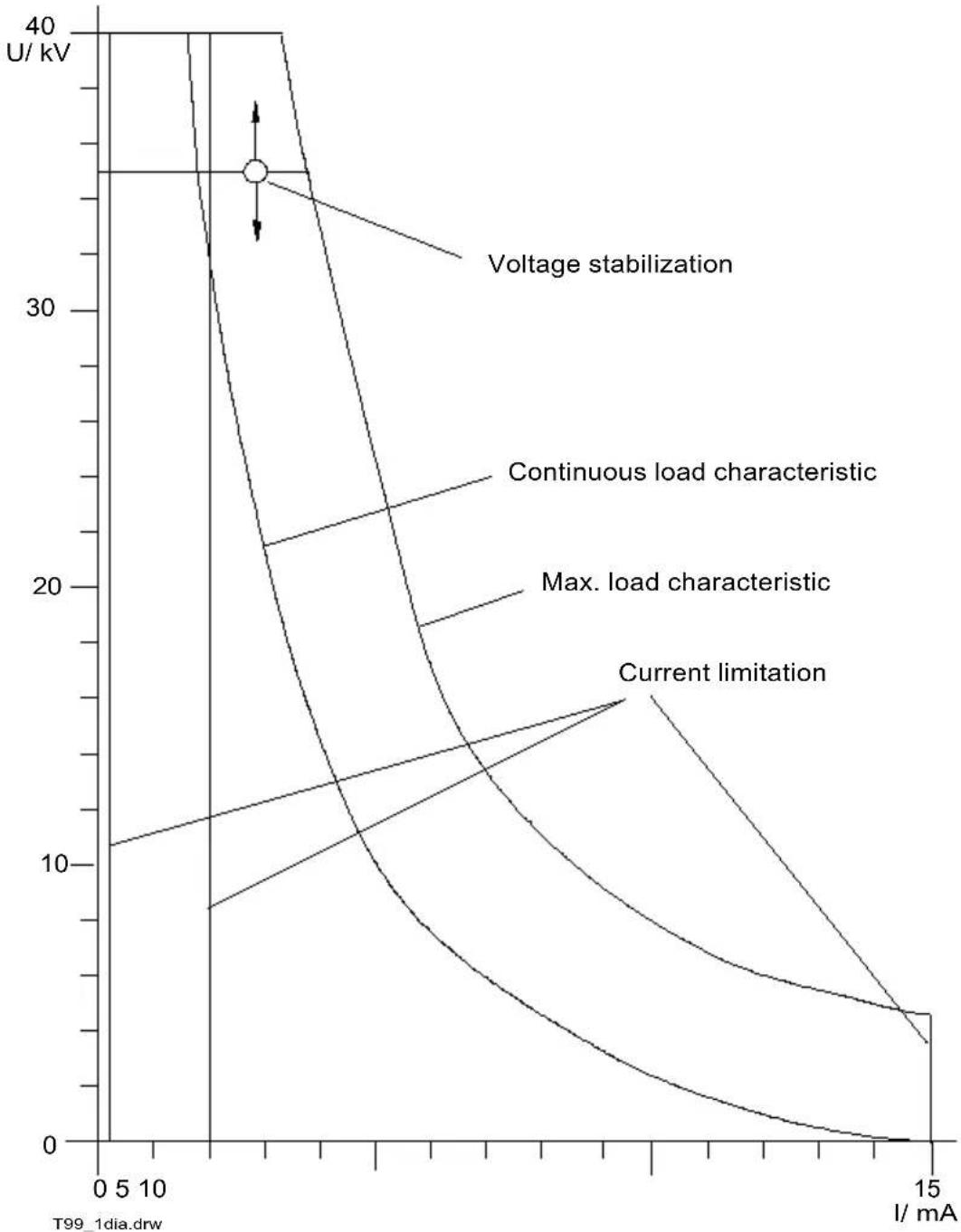
The dynamic behaviour of the relaxation-type converter and cascades is in accordance with a constant power characteristic. That means that the current and voltage response within a wide range is such that constant power is supplied to the load resistor (leakage resistance) independently of its size.
This is the ideal response for a pure burning set. In the case of a test set, this current-voltage characteristic has to be corrected for the particular type of application.
A test set must maintain the set test voltage within the usual range of leakage currents, i.e. a few milliamperes, to avoid having to make continuous readjustments in the event of variations in current and mains voltage.
The voltage stabilization takes care of this. A feedback signal derived from the output voltage influences the duty cycle of the relaxation-type converter.
The constant voltage range is followed by the constant power range, with voltage and current being regulated in such a way that the full power available to the test set is applied to the test object.
This range is passed through quickly during charging. The test set is able to charge 1 mF to 40 kV in 10 s. This range is followed by the constant current range. The task here is to supply a current which makes it possible to burn down a fault with a flashover voltage of 10 kV. Experience shows that 10...20 mA is sufficient to do this.
A powerful burn unit such as the T 22/13 B can then be used for burning out. The current control has been set to approx. 15 mA out of consideration for the rectifiers used.
This applies to the 20 mA setting of the current measurement range switch. In the 200 and 2 mA ranges the control limits the current to the measuring range end values, with them only be exceeded momentarily when flashover occurs, at which point the overcurrent trip comes into effect.
Fig. 1 shows the current-voltage characteristic for the test set.
line
| I/ mA | Voltage stabilization | Continuous load characteristic | Max. load characteristic | Current limitation | |-------|------------------------|----------------------------------|--------------------------|--------------------| | 0 | 40 | 10 | 10 | 10 | | 5 | 35 | 12 | 12 | 12 | | 10 | 30 | 15 | 15 | 15 | | 15 | 25 | 20 | 20 | 20 |Fig. 1 Current-voltage characteristic, T 99/1
The technology described provides an extremely constant voltage during testing, yet also allows quick charging. In addition, it is possible to perform pre-burning and prelocation with the T 01/6 Teleflex using the decay method, with the power consumption remaining of an order of magnitude which also permits extended operation off the external battery.
The output current and output voltage are displayed on separate instruments to make it easier to determine the insulation resistance.
The voltmeter has a full-scale deflection of 40 kV.
The ammeter has three ranges with full-scale deflections of 200 mA, 2 mA and 20 mA.
The test set has the following features to facilitate measurement and protect the operator:
a) Switch-on interlock system
The high voltage cannot be switched on by pressing the "On" button until the voltage adjustment potentiometer has been turned as far anticlockwise as it will go (zero setting).
b) Discharge device
When the unit is shut down by the time switch and when the "Discharge" button is pressed, the test object is discharged by a discharge device. The max. discharge energy is 8 kJ, corresponding to 10 mF at 40 kV. The "Discharge" switch allows the operator to activate the discharge device and switch off the high-voltage generator without disabling the control and measurement electronics, retaining the voltage indication and thereby ensuring the safety of the operator. This function is also retained if the test set shuts down automatically.
c) Overcurrent tripping
If the current exceeds the measuring range end value, e.g. by approx. 10% in the 2 mA range, the high voltage shuts down. To make it possible to also detect momentary flashovers which do not lead to full discharge of the test object, the test set does not cause a discharge in the event of overcurrent tripping.
d) Time switch
A test time of up to one hour can be preselected using a time switch. When the time expires, the high voltage shuts down and the test object is discharged.
e) Reverse voltage protection during battery operation
If a battery is connected with wrong polarity, a protective diode prevents current from flowing. The test set will not be damaged. Operation with 230 VAC and 12 VDC connected simultaneously must be avoided at all costs.
f) Travelling-wave protection
The cascade vessel houses a resistor for travelling-wave protection which protects the test set when a flashover occurs in the cable.
CHAPTER 3
OPERATION
3. OPERATION
3.1. Safety measures
The following safety measures must be complied with to avoid personal injury or material damage as a direct result of operation of the T 99/1 by itself or in combination with other equipment:
- Check the immediate area surrounding where the T 99/1 is being used for any unprotected live equipment/plant components with which you or the unit might unintentionally come into contact. In particular, this applies to high-voltage components (>25 VAC / >60 VDC) and components with an unknown voltage.
Protect such components by fitting insulating covers. If this is not possible for technical reasons, switch such components off or have this done for you for the duration of your work at this site by prior agreement with/with the prior approval of the supervisor responsible. Make sure that this has been done properly (e.g. by performing control measurements with a multimeter which you have checked for proper functioning before taking measurements: perform a control measurement on a known voltage, etc.).
Perform a control measurement, e.g. with a multimeter. Before doing so, make sure that the test meter is working properly, e.g. by performing a control measurement on a known voltage.
- Choose a site for the unit that satisfies weight and dimension requirements and provides a secure "base".
- Make sure that the proper functioning of other equipment/plant components is not impaired by the installation of the T 99/1. If other equipment/plant components have to be modified to accommodate the installation and operation of the generator, make sure that such measures are reversed once the work has been completed. The special requirements of such equipment/plant must be complied with, and only perform work in this connection by prior agreement with/with the prior approval of the supervisor responsible.
This is particularly important in the case of interference with existing safety devices.
3.2. Controls

Fig. 2 Front view
1 Jack for battery
2 Amperemeter
3 Voltmeter
4 Socket for HV connecting cable
5 High voltage "On" button
6 Protective ground terminal
7 Voltage control
8 Discharge button
9 Time switch
10 Overcurrent lamp
11 Current measuring range switch
12 Overcurrent trip "On"
13 Mains/battery "On"lamp
14 Mains jack
15 Mains fuses
16 "Overload" lamp
17 "On/Off" switch
3.3. Start-up
CAUTION: Please note that all safety regulations concerning the use of high-voltage equipment must be complied with when the test set is started up. (see section 1.1.)
3.3.1. Preparing for a measurement
Power supply
The test set can be run off either the 115/230 V / 50-60 Hz AC mains or a 12 V battery. It is wired for 230 V when supplied and can be changed over to 115 V by resoldering jumpers on the transformer (see fig. 3).
NB: Fuses will have to be replaced if the test set is rewired for 115 V operation (see fig. 4).
In the case of mains operation, jack (14) must be connected to the mains with the 0336 mains lead.
In the case of battery operation, the battery (preferably a 12 V car battery) must be connected to the battery jack (1) with the battery lead.
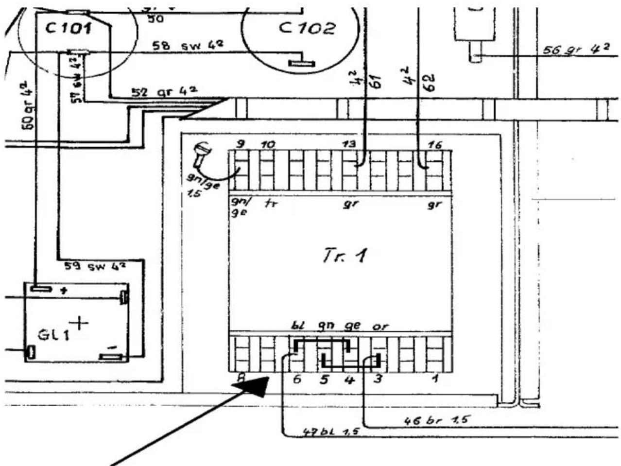
Soldering jumpers for 115 V operation
Fig. 3 Rewiring for 115 V
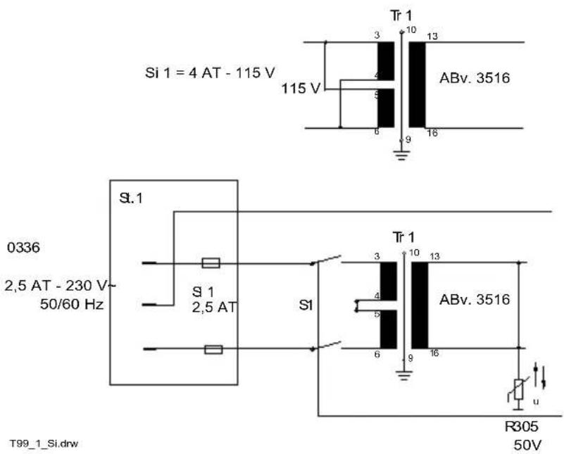
Fig. 4 Replacement of fuses for 115 V operation
3.3.2. Testing the test set for correct functioning
The cascades for high-voltage generation are housed in a vessel filled with the insulating gas sulphur hexafluoride (SF6). The operating pressure is 0.1 bar.
The gas vessel contains a protective spark gap which is activated in the event of a gas leak or poor insulating ability on the part of the gas before a component is put at risk.
If the test set has been idle for an extended period, it should be run up to maximum voltage (40 kV) with the high-voltage plug disconnected to check the quality of the insulating gas. The current measuring range should be set to 200 mA and the overcurrent trip switched on.
If the high voltage shuts down while the test set is being run up, the protective spark gap has been activated.
In the worst case, the gas will then have to be replaced.
To do this, the test set has to be opened. Connect the H 909 filling device to the filler valve visible on the cascade vessel and top the vessel up with SF6 from a gas bottle. Position the test set in such a way that the filler valve is at the highest point of the vessel.
Now fill the vessel to 0.1 bar positive pressure and then reduce to atmospheric pressure. Repeat this process at least 10 times. Finally, check the dielectric strength again.
The test set can always be operated below the threshold voltage of the protective spark gap and cable testing performed. The protective spark gap may also be activated during cable testing.
If this happens, the cable capacitance is discharged via the spark gap and discharge resistor.
3.3.3. Connecting the test object
First of all, before the test object as such is connected, the protective ground connection has to be established. This is done using the 0313 protective ground cable, one end of which should be connected to the wing screw (6) and the other end to a frame ground with a low-impedance ground connection.
A low impedance connection must also be established between the protective ground and the station ground (cable sheath).
The K 705 high-voltage connecting cable must only be connected if the test object is dead and grounded. Disconnection from ground is the last step before starting testing, and reconnection to is the first step before disconnecting the test object.
WARNING: Terminals which are not grounded must not be touched even with the test set switched off (recharging). The station ground connection must be established before the high-voltage connection.

Fig. 5 Connection
If only one connection to ground is available, the protective and station grounds may both be connected to it, but using separate cables and separate terminals, and as far from each other as possible, making sure that the station ground connection is closer to the cable sheath.
3.3.4. Performing measurements
- Switch the test set on using the toggle switch (17).
- Lamp (13) lights up
- Switch the high voltage on with button (5)
Only possible if the voltage control (7) has been turned as far anticlockwise as it will go.
- Lamp in button (5) lights up
- Turn the current measuring range switch (11) to the measuring range which corresponds to the current with which the test object is to be charged. Set the time switch (9) to the required test time.
Switch (11) simultaneously switches to the current measuring range and the maximum current that the current limiting circuitry will allow. In the first two switch positions the maximum value is approx. 120% of the measuring range end value. In the 20 ~mA range it is approx. 15 ~mA .
For charging with maximum current, set the switch to 20 mA as in the case of burning and decay measurements.
- Set the required voltage roughly using the voltage control (7).
Watch the voltmeter (3) carefully during charging. If necessary, correct the voltage control (7) before the required test voltage is reached.
- Once charging has been completed, set the current measuring range switch (11) to the required measuring range.
- When the test time has expired, the high voltage is shut down and the test object discharged.
If the time switch is not used, press the discharge button (8) when testing is complete
- This also shuts down the high voltage and discharges the test object.
In both cases the test set remains on so that the ammeter and voltmeter can be used to check that discharging is complete.
- If switch (12) is set to " ", the high voltage is shut down if the end value in the first two current measuring ranges is exceeded by approx. 10%.
- If this happens, the indicator lamp (10) lights up. It will also remain on if the test object is discharged by the time switch, for example.
This means that the operator can see whether a flashover occurred during the test time even once the time has expired. The overcurrent trip does not cause the test object to be discharged. This makes it possible to detect momentary voltage drops which do not lead to full discharge and only cause momentary current peaks.
- When measuring has been completed, turn the test set off with switch (17).
- If discharging has not yet taken place, it will be done now.
- Ground the test object properly before disconnecting it.
If the test set is operated in the overload range (see fig. 1) for an extended period, the high voltage may shut down. If this happens, lamp (16) will light up. The high voltage can only be switched on again once the test set has cooled down sufficiently.
This symbol indicates that the product which is marked in this way should not be disposed of as normal household waste. As it is a B2B product, it may also not be disposed of at civic disposal centres. If you wish to dispose of this product, please do so properly by taking it to an organisation specialising in the disposal of old electrical equipment near you.
- TERMS AND CONDITIONS OF WARRANTY
- EC-Declaration of conformity CE Mark
- kV Test Set T 99/1
- Table of figures......8
- SAFETY INSTRUCTIONS 13
- TECHNICAL DESCRIPTION 21
- OPERATION 31
- CHAPTER 1
- SAFETY INSTRUCTIONS
- SAFETY INSTRUCTIONS
- General instructions
- Electrotechnical instructions
- General rules for working with high voltages
- Supplementary instructions
- Danger of recurring voltage from space charges
- Indications used in the description
- CHAPTER 2
- TECHNICAL DESCRIPTION
- TECHNICAL DESCRIPTION
- Specification
- Scope of supply and accessories
- Scope of supply T 99/1 40 kV test set
- Accessories
- General functional description
- Description of the T 99/1 40 kV test set
- Performance features
- Design and working method
- c) Overcurrent tripping
- d) Time switch
- e) Reverse voltage protection during battery operation
- f) Travelling-wave protection
- OPERATION
- Safety measures
- Controls
- Start-up
- Preparing for a measurement
- Power supply
- Testing the test set for correct functioning
- Connecting the test object
- Performing measurements
Brand : Megger
Model : T99/1
Category : Measurement