IFGS-1022HPT - Network switch Planet - Free user manual and instructions
Find the device manual for free IFGS-1022HPT Planet in PDF.


| Product Type | Industrial Gigabit PoE+ Switch |
| Model | IFGS-1022HPT |
| Ports | 22 x 10/100/1000Base-T PoE+ (802.3at), 2 x Gigabit SFP uplink |
| PoE Budget | 250W total, up to 30W per port |
| Switching Capacity | 48 Gbps |
| Forwarding Rate | 35.7 Mpps |
| MAC Address Table | 8K entries |
| VLAN Support | 802.1Q VLAN (up to 256 groups) |
| Management | Web GUI, SNMP v1/v2c/v3, CLI via console, Telnet/SSH |
| Power Supply | AC 100-240V, 50/60Hz, internal redundant power input (dual DC optional) |
| Power Consumption | 30W (no PoE), 300W max with full PoE load |
| Dimensions (W x D x H) | 440 x 220 x 44 mm (1U rackmount) |
| Weight | 3.2 kg |
| Operating Temperature | -40°C to 75°C |
| Cooling | Fanless (natural convection) |
| Safety Certification | CE, FCC, UL 60950-1 |
| Cleaning and Maintenance | Wipe with dry cloth; do not use liquids or sprays. Keep vents free of dust. |
| Spare Parts and Repairability | No user-serviceable parts. Contact Planet support for replacement power supply or fan. |
| General Information | Industrial grade, DIN-rail or rack mount, supports PoE watchdog and auto-recovery. |
Frequently Asked Questions - IFGS-1022HPT Planet
User questions about IFGS-1022HPT Planet
0 question about this device. Answer the ones you know or ask your own.
Ask a new question about this device
Download the instructions for your Network switch in PDF format for free! Find your manual IFGS-1022HPT - Planet and take your electronic device back in hand. On this page are published all the documents necessary for the use of your device. IFGS-1022HPT by Planet.
USER MANUAL IFGS-1022HPT Planet
Industrial 8-Port 10/100TX 802.3at PoE+ plus 2-Port Gigabit TP/SFP Combo Ethernet Switch
IFGS-1022HPT
User's Manual
Table of Contents
- Package Contents.... 3
- Hardware Introduction 4
2.1 Physical Dimensions.... 4
2.2 Switch Front Panel....5
2.3 LED Indicators....7
2.4 Switch Upper Panel 8
2.5 Wiring the Power Inputs....8
2.6 Wiring the Fault Alarm Contact 9
2.7 Product Features....10
2.8 Product Specifications ....11
- Installation ....14
3.1 DIN-rail Mounting Installation 14
3.2 Wall-mount Plate Mounting....16
3.3 Installing the SFP Transceiver ....17
3.4 Removing the Transceiver Module....18
- Troubleshooting....19
APPENDIX A: Networking Connection....20
A.1 PoE RJ45 Port Pin Assignments (End-span) 20
A.2 Switch's RJ45 Pin Assignments ....20
A.3 RJ45 Cable Pin Assignments....21
A.4 Fiber Optic Cable Connection Parameter 22
APPENDIX B: Approved PLANET SFP Transceivers 23
1. Package Contents
Thank you for purchasing PLANET industrial 8-Port 10/100TX 802.3at PoE+ plus 2-Port Gigabit TP/SFP combo Ethernet Switch, IFGS-1022HPT. In the following sections, the term "Industrial PoE+ Switch" means the IFGS-1022HPT.
Open the box of the Industrial PoE+ Switch and carefully unpack it. The box should contain the following items:
| Industrial PoE+ Switch x 1 QR Code Sheet x 1 | |
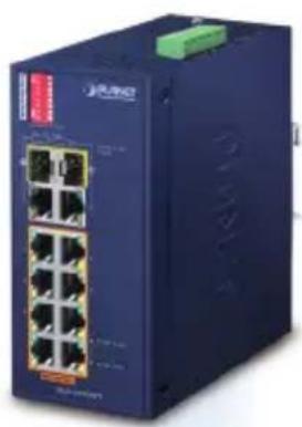 |  |
| DIN-rail Kit x 1 Wall-mount Kit x 1 | |
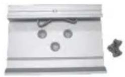 | 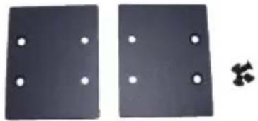 |
If any of these are missing or damaged, please contact your dealer immediately; if possible, retain the carton including the original packing material, and use them again to repack the product in case there is a need to return it to us for repair.
2. Hardware Introduction
2.1 Physical Dimensions
■ Dimensions (W x D x H): 66 x 107 x 152 mm
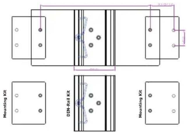
Unit: mm
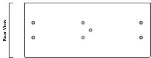
natural_image
Simple diagram showing four circles arranged in two groups within a rectangle labeled 'Rear View' (no text or symbols on the circles)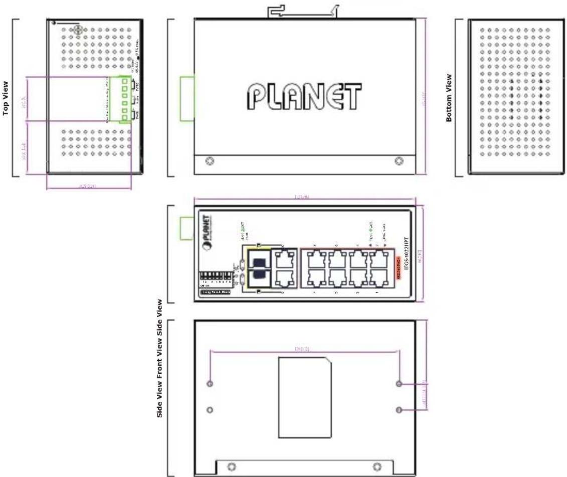
2.2 Switch Front Panel
The front panel of the Industrial PoE+ Switch consists of 8 10/100/BASE-TX ports featuring 30-watt 802.3at PoE+, and 2 additional Gigabit copper/SFP combo interfaces for Gigabit Ethernet extension and video uplink. The LED indicators are also located on the front panel of the Industrial PoE+ Switch.
Figure 2-1 shows the front panel of Industrial PoE+ Switch.
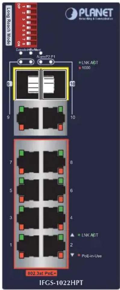
Figure 2-1: IFGS-1022HPT Front Panel
■ Fast Ethernet TP interfaces (Port 1 to port 8)
10/100BASE-TX copper, RJ45 twisted-pair: Up to 100 meters.
■ Gigabit TP/SFP Combo Interfaces (Port 9 to port 10)
10/100/1000BASE-T copper, RJ45 twisted-pair: Up to 100 meters.
■ Gigabit SFP/SFP Combo Interfaces (Port 9 to port 10)
1000BASE-SX/LX mini-GBIC slot, SFP (small factor pluggable) transceiver module: From 550 meters (multi-mode fiber) to 10/20/40/80/120 kilometer (single-mode fiber or WDM fiber).
DIP Switch
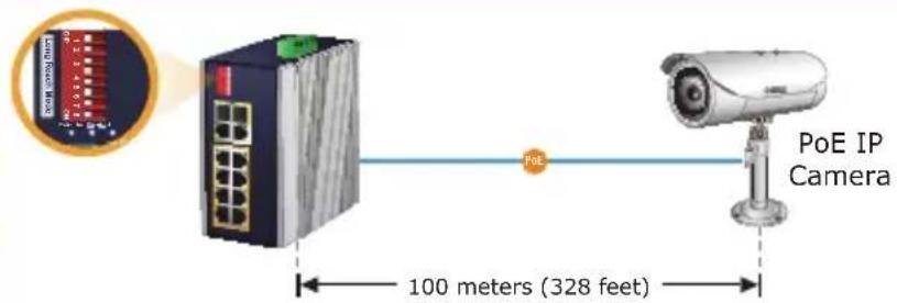
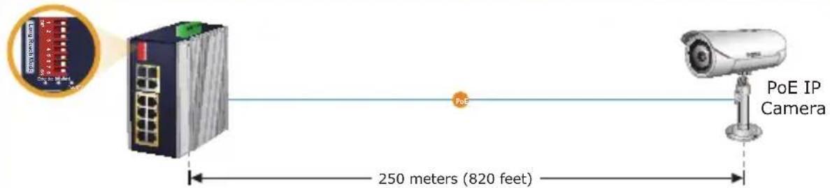
The Industrial PoE+ Switch has a built-in solid DIP switch that provides "Standard" and "Extend" operation modes. The Industrial PoE+ Switch operates as a normal IEEE 802.af/at PoE+ Switch in the "Standard" operation mode.
In the "Extend" operation mode, the Industrial PoE+ Switch operates on a per-port basis at 10Mbps full duplex operation but can support 30-watt PoE power output over a distance of up to 250 meters overcoming the 100m limit on Ethernet UTP cable. With this brand-new feature, the Industrial PoE+ Switch provides an additional solution for 802.3af/at PoE+ distance extension.
Default PoE Mode
Extended PoE Mode
PoE 100BASE-TX UTP with PoE
2.3 LED Indicators
System
| LED Color Function | ||
| P1 Green Lit: Indicates power 1 has power. | ||
| P2 Green Lit: Indicates power 2 has power. | ||
| Alarm | Red | Lit: Indicates neither power 1 nor power 2 has power. |
Per 802.3at PoE+ 10/100BASE-TX Interface (Port 1 to Port 8)
| LED Color Function | ||
| LNK/ACT | Green | Lit: Indicates the link through that port is successfully established at 10Mbps or 100Mbps.Blinking: Indicates that the switch is actively sending or receiving data over that port. |
| PoE In-Use | Amber | Lit: Indicates the port is providing DC in-line power.Off: Indicates the connected device is not a PoE powered device (PD). |
Per 10/100/1000BASE-T Interface (Shared with Port 9 to Port 10)
| LED Color Function | ||
| LNK/ACT | Green | Lit: Indicates the link through that port is successfully established at 10/100/1000Mbps.Blinking: Indicates that the switch is actively sending or receiving data over that port. |
| 1000 Amber | Lit: Indicates the link through that port is successfully established at 1000Mbps.Off: Indicates the link through that port is successfully established at 10/100Mbps. | |
Per 1000X SFP Slot (Shared with Port 9 to Port 10)
| LED Color Function | ||
| LNK/ACT | Green | Lit: Indicates the link through that port is successfully established at 1000Mbps.Blinking: Indicates that the switch is actively sending or receiving data over that port. |
| 1000 Amber | Lit: Indicates the link through that port is successfully established at 1000Mbps.Off: Indicates the link through that port is not established. | |
2.4 Switch Upper Panel
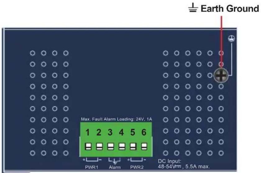
The upper panel of the Industrial PoE+ Switch consists of one terminal block connector within two DC power inputs.
Figure 2-2 shows the upper panel of the Industrial PoE+ Switch.
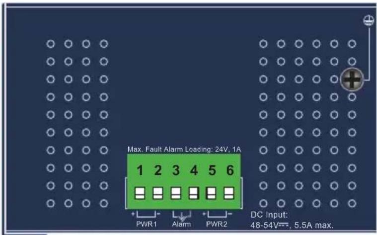
Figure 2-2: Industrial PoE+ Switch Upper Panel
2.5 Wiring the Power Inputs
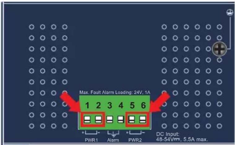
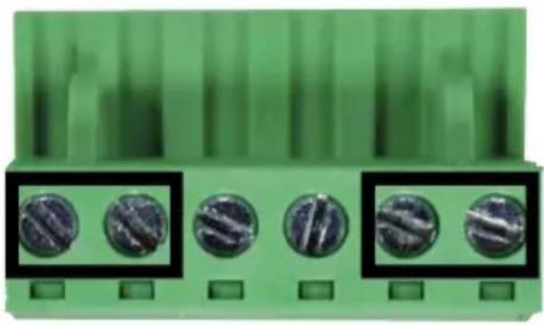
The 6-contact terminal block connector on the top panel of Industrial PoE+ Switch is used for two DC redundant power inputs. Please follow the steps below to insert the power wire.

When performing any of the procedures like inserting the wires or tightening the wire-clamp screws, make sure the power is OFF to prevent from getting an electric shock.
- Insert positive and negative DC power wires into Contacts 1 and 2 for Power 1, or Contacts 5 and 6 for Power 2.
- Tighten the wire-clamp screws for preventing the wires from loosening.
natural_image
Close-up of a green electronic component with five circular screw holes, shown in black boxes (no text or symbols visible)123456
Power 1 Alarm Power 2
+ - + -

Note
- The wire gauge for the terminal block should be in the range between 12 and 24 AWG.
- The DC power input range is 48V \~ 54V DC.

Caution
PWR1 and PWR2 must provide exactly the same DC voltage for power load balance while operating with dual power input.
Grounding the Device
Users MUST complete grounding wired with the device; otherwise, a sudden lightning could cause fatal damage to the device.
2.6 Wiring the Fault Alarm Contact
The fault alarm contacts are in the middle of the terminal block connector as the picture shows below. Inserting the wires, the Industrial PoE+ Switch will detect the fault status of the power failure and then forms an open circuit. The following illustration shows an application example for wiring the fault alarm contacts.
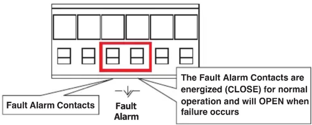
Insert the wires into the fault alarm contacts

Note
- The wire gauge for the terminal block should be in the range between 12 and 24 AWG.
- Alarm relay circuit accepts up to 24V with a maximum current of 1A.
2.7 Product Features
Physical Port
- Eight 10/100BASE-TX Fast Ethernet RJ45 ports with IEEE 802.3at/af PoE+ injector function (Port 1 to Port 8)
- Two 10/100/1000BASE-T Gigabit Ethernet RJ45 ports (Port 9 and Port 10)
- Two 1000BASE-X mini-GBIC/SFP slots for SFP type auto detection (Port 9 and Port 10)
Power over Ethernet
● Complies with IEEE 802.3at Power over Ethernet Plus, end-span PSE
● Backward compatible with IEEE 802.3af Power over Ethernet
- Up to 8 ports of IEEE 802.3af/802.3at devices powered
● 240-watt PoE budget
● Supports PoE power up to 30 watts for each PoE port
- Auto detects PD
● Circuit protection prevents power interference between ports
● Remote power feeding up to 100 meters
Industrial Case and Installation
IP30 metal case
• DIN-rail and wall-mount designs
- 48\~54V DC, redundant power with reverse polarity protection
● Supports 6000V DC Ethernet ESD protection
- -40 to 75 degrees C operating temperature
Switching
- Hardware-based 10/100Mbps (half/full duplex), 1000Mbps (full duplex), auto-negotiation and auto MDI/MDI-X
- Features Store-and-Forward mode with wire-speed filtering and forwarding rates
- IEEE 802.3x flow control for full duplex operation and back pressure for half duplex operation
• 16K MAC address table size
- 10K jumbo frame
- IEEE 802.1Q VLAN transparency
- Hardware-based DIP switch for "Standard" and "Extend" mode selection; the "Extend" mode features 30-watt PoE transmission distance of 250m at speed of 10Mbps
● Automatic address learning and address aging
● Supports CSMA/CD protocol
2.8 Product Specifications
| Product IFGS-1022HPT | |
| Hardware Specifications | |
| Fast Ethernet Copper Ports | Eight 10/100BASE-TX RJ45 auto-MDI/MDI-X ports (Ports 1 to 8) |
| Gigabit Ethernet Copper Ports | Two 10/100/1000BASE-T RJ45 auto-MDI/MDI-X ports (shared with Ports 9 to 10) |
| SFP/mini-GBIC Slots | Two 1000BASE-SX/LX/BX SFP interfaces (shared with Ports 9 to 10) |
| PoE Injector Port | Eight ports with 802.3af/802.3at PoE+ injector function (Ports 1 to 8) |
| DIP Switch (Port-1 to Port-8) | Standard mode: 30-watt PoE transmit distance of 100m at speed of 10/100Mbps Extend mode: 30-watt PoE transmit distance of 250m at speed of 10Mbps |
| Connector | Removable 6-pin terminal block■ Pin 1/2 for Power 1■ Pin 3/4 for power fault alarm■ Pin 5/6 for Power 2 |
| Alarm | One relay output for power failure. Alarm relay current carry ability: 1A @ 24V AC |
| Power Requirements | 48~54V DC, 5.5A (max.) (>51V DC for PoE+ output recommended) |
| Power Consumption/Dissipation | 4.3 watts, 14.6BTU (Standby without PoE function) at DC 54V power input 256 watts, 873BTU (Full loading with PoE function) at DC 54V power input |
| Dimensions (W x D x H) 66 | x 107 x 152 mm |
| Weight 829g | |
| ESD Protection 6KV DC | |
| Enclosure IP30 metal case | |
| Installation DIN-rail kit and wall-mount kit | |
| LED | 3 x LED for System and Power:■ Green: DC Power 1■ Green: DC Power 2■ Red: Power Fault Alarm2 x LED for PoE Copper Port (Ports 1 to 8):■ Green: LNK/ACT (10/100Mbps)■ Amber: PoE-In-Use2 x LED for 10/100/1000T Copper Port(Ports 9 to 10):■ Green: LNK/ACT■ Amber: 10002 x LED for per mini-GBIC interface(Ports 9 to 10)■ Green: LNK/ACT■ Amber: 1000 |
| Switching Specifications | |
| Switch Architecture Store-and-Forward | |
| Switch Fabric 5.6Gbps/non-blocking | |
| Switch Throughput@64 bytes | 4.1Mpps @64 bytes |
| MAC Address Table 16K entries | |
| Shared Data Buffer 4Mb SRAM | |
| Flow Control | IEEE 802.3x pause frame for full duplexBack pressure for half duplex |
| Jumbo Frame 10 Kbytes | |
| Power over Ethernet | |
| PoE Standard IEEE 802.3at | Power over Ethernet Plus/PSE |
| PoE Power Supply Type End-span | |
| Power Pin Assignment 1/2(+), 3/6(-) | |
| PoE Power Output | IEEE 802.3af Standard- Per port 48V~51V DC (depending on the power supply), max. 15.4 watts IEEE 802.3at Standard- Per port 51V~54V DC (depending on the power supply), max. 30 watts |
| PoE Power Budget | Dual power input: maximum 240W (depending on power input) |
| Max. Number of Class 2 PDs | 8 |
| Max. Number of Class 3 PDs | 8 |
| Max. Number of Class 4 PDs | 8 |
| Standards Conformance | |
| Regulatory Compliance FCC | Part 15 Class A, CE |
| Stability Testing | IEC 60068-2-32 (free fall)IEC 60068-2-27 (shock)IEC 60068-2-6 (vibration) |
| Standards Compliance | IEEE 802.3 10BASE-TIEEE 802.3u 100BASE-TXIEEE 802.3ab Gigabit 1000BASE-TIEEE 802.3z Gigabit SX/LXIEEE 802.3x Flow Control and Back PressureIEEE 802.3af Power over EthernetIEEE 802.3at Power over Ethernet Plus |
| Environment | |
| Operating Temperature -40 | ~ 75 degrees C |
| Storage Temperature -40 ~ | 85 degrees C |
| Humidity 5 ~ 95% (non-condensing) | |
3. Installation
This section describes the functionalities of the Industrial PoE+ Switch's components and guides you to installing it on the DIN-rail and wall. Basic knowledge of networking is assumed. Please read this chapter completely before continuing.

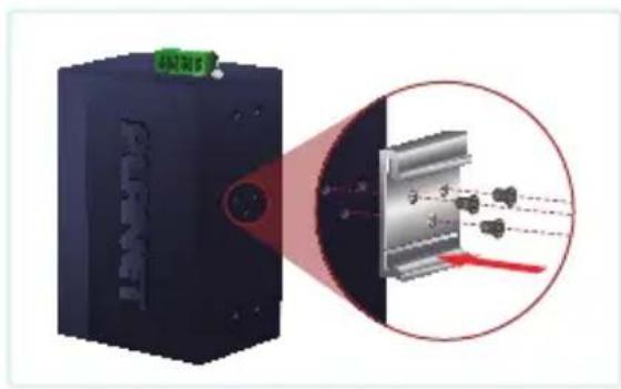
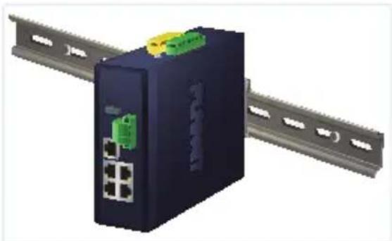
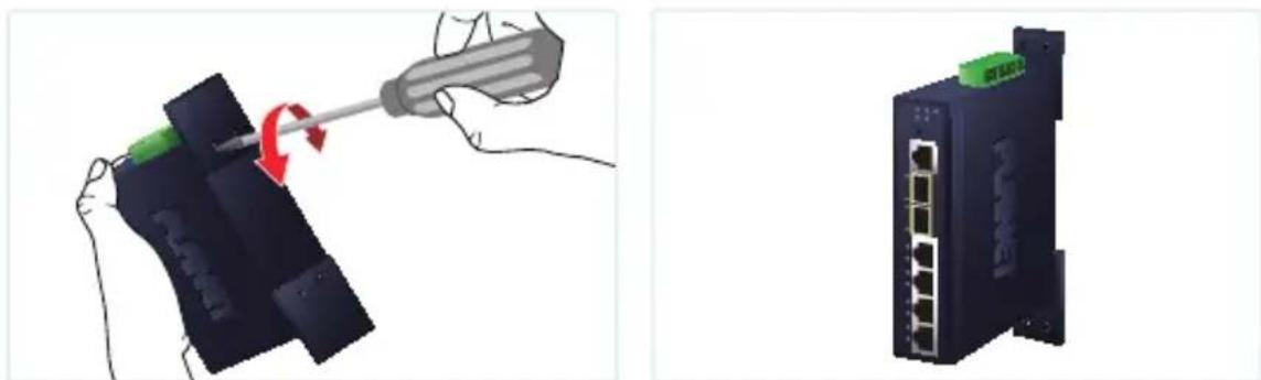
This following picture shows the user how to install the device, and the device is not IFGS-1022HPT.
3.1 DIN-rail Mounting Installation
natural_image
Diagram showing a device emitting laser beam through a lens system, with an inset close-up of the component (no text or symbols)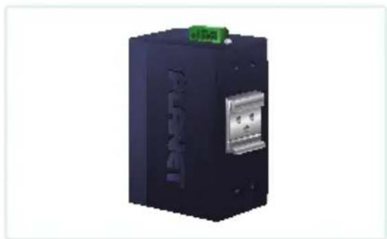
natural_image
Exterior view of a black electronic device with a metallic connector and green logo (no visible text or symbols)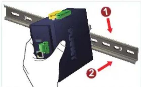
natural_image
3D rendering of a network switch device with ports and connectors, connected to a rail (no text or symbols visible)3.2 Wall-mount Plate Mounting
natural_image
Illustration showing a hand using a screwdriver to adjust or install a device, with no visible text or symbols.3.3 Installing the SFP Transceiver
The sections describe how to insert an SFP transceiver into an SFP slot.
The SFP transceivers are hot-pluggable and hot-swappable. You can plug in and out the transceiver to/from any SFP port without having to power down the Industrial PoE+ Switch as Figure 3-1 shows.
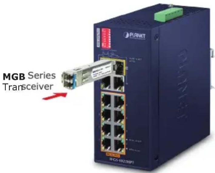
Figure 3-1: Plugging in the SFP Transceiver
PLANET Industrial PoE+ Switch supports 1000Mbps mode with both single mode and multi-mode SFP transceivers.
-
Before we connect Industrial PoE+ Switch to the other network device, we have to make sure both sides of the SFP transceivers are with the same media type, for example, 1000BASE-SX to 1000BASE-SX, 1000BASE-LX to 1000BASE-LX.
-
Check whether the fiber-optic cable type matches with the SFP tra requirement.
- To connect to 1000BASE-SX SFP transceiver, please use the multi-mode fiber cable with one side being the male duplex LC connector type.
- To connect to 1000BASE-LX or 1000BASE-BX SFP transceiver, please use the single-mode fiber cable with one side being the male duplex LC connector type.
■ Connecting the Fiber Cable
- Insert the duplex LC connector into the SFP transceiver.
- Connect the other end of the cable to a device with SFP transceiver installed.
- Check the LNK/ACT LED of the SFP slot on the front of the Industrial PoE+ Switch. Ensure that the SFP transceiver is operating correctly.
- Check the Link mode of the SFP port if the link fails.

Note
It is recommended to use PLANET SFPs on the Industrial PoE+ Switch. If you insert an SFP transceiver that is not supported, the Industrial PoE+ Switch will not recognize it.
3.4 Removing the Transceiver Module
- Make sure there is no network activity by consulting or checking with the network administrator. Or through the management interface of the switch/converter (if available) to disable the port in advance.
- Remove the Fiber Optic Cable gently.
- Turn the lever of the MGB series module to a horizontal position.
- Pull out the module gently through the lever.
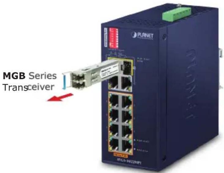
Figure 3-2: Pulling Out the Transceiver

Note
Never pull out the module without pulling the lever or the push bolts on the module. Directly pulling out the module with force could damage the module and the SFP module slot of the Industrial PoE+ Switch.
4. Troubleshooting
This chapter contains information to help you solve issues. If the Industrial PoE+ Switch is not functioning properly, make sure the Industrial PoE+ Switch was set up according to instructions in this manual.
The per port LED is not lit
Solution:
Check the cable connection of the Industrial PoE+ Switch.
Per port LED is lit, but the traffic is irregular
Solution:
Check whether the attached device is not set to dedicated full duplex. Some devices use a physical or software switch to change duplex modes. Auto-negotiation may not recognize this type of full-duplex setting.
Why the Industrial POE+ Switch doesn't connect to the network
Solution:
Check each port LED on the Industrial PoE+ Switch. Try another port on the Industrial PoE+ Switch. Make sure the cable is installed properly and the right type. Turn off the power. After a while, turn on the power again.
Can I install MGB-SX or other non wide temperature SFP module into SFP slot of Industria PoE+ Switch?
Solution:
Yes, you can. However, the MGB-SX and the other non wide temperature SFP module cannot operate under -40 to 75 degrees C.
APPENDIX A: Networking Connection
A.1 PoE RJ45 Port Pin Assignments (End-span)
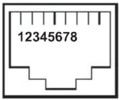 | PIN NO RJ45 POWER ASSIGNMENT | |
| 1 Power + | ||
| 2 Power + | ||
| 3 Power - | ||
| 6 Power - | ||
A.2 Switch's RJ45 Pin Assignments
1000Mbps, 1000BASE-T
| Contact MDI MDI-X | |
| 1 BI_DA+ BI_DB+ | |
| 2 BI_DA- BI_DB- | |
| 3 BI_DB+ BI_DA+ | |
| 4 BI_DC+ BI_DD+ | |
| 5 BI_DC- BI_DD- | |
| 6 BI_DB- BI_DA- | |
| 7 BI_DD+ BI_DC+ | |
| 8 BI_DD- BI_DC- |
10/100Mbps, 10/100BASE-TX
| RJ45 Connector Pin Assignment | ||
| Contact | MDIMedia Dependent Interface | MDI-XMedia Dependent Interface -- Cross |
| 1 Tx + (transmit) | Rx + (receive) | |
| 2 | Tx - (transmit) Rx - (receive) | |
| 3 | Rx + (receive) | Tx + (transmit) |
| 4, 5 | Not used | |
| 6 | Rx - (receive) | Tx - (transmit) |
| 7, 8 | Not used | |
A.3 RJ45 Cable Pin Assignments
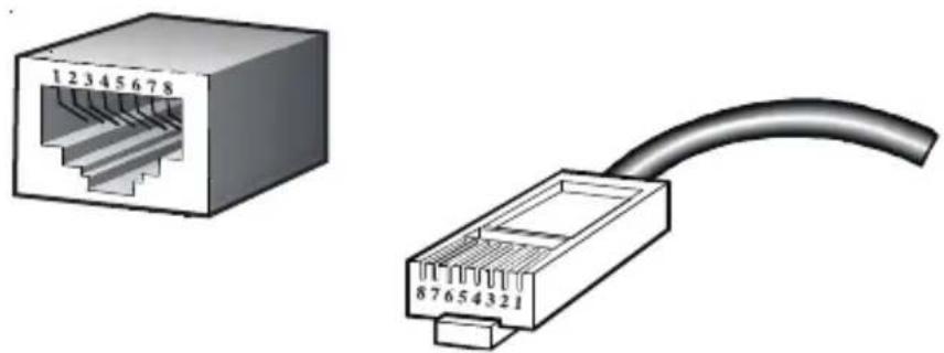
natural_image
Two types of Ethernet connectors shown: one with a 12345678 port, the other with a black cable (no text or symbols)The standard RJ45 receptacle/connector
There are 8 wires on a standard UTP/STP cable and each wire is color-coded. The following shows the pin allocation and color of straight-through cable and crossover cable connection:
| Straight Cable | SIDE 1 | SIDE 2 | |
| 1 2 3 4 5 6 7 8 1 2 3 4 5 6 7 8 | SIDE 1 | 1 = White/Orange 2 = Orange 3 = White/Green 4 = Blue 5 = White/Blue 6 = Green 7 = White/Brown 8 = Brown | 1 = White/Orange 2 = Orange 3 = White/Green 4 = Blue 5 = White/Blue 6 = Green 7 = White/Brown 8 = Brown |
| Crossover Cable | SIDE 1 SIDE 2 | ||
| 1 2 3 4 5 6 7 8 1 2 3 4 5 6 7 8 | SIDE 1 | 1 = White/Orange 2 = Orange 3 = White/Green 4 = Blue 5 = White/Blue 6 = Green 7 = White/Brown 8 = Brown | 1 = White/Green 2 = Green 3 = White/Orange 4 = Blue 5 = White/Blue 6 = Orange 7 = White/Brown 8 = Brown |
Figure A-1: Straight-through and Crossover Cables
Please make sure your connected cables are with the same pin assignment and color as the above picture before deploying the cables into your network.
A.4 Fiber Optic Cable Connection Parameter
The wiring details are shown below:
1000X Fiber Optic Cables:
| Standard Fiber Type Cable Specifications | |
| 1000BASE-SX (850nm) | Multi-mode 50/125μm or 62.5/125μm |
| 1000BASE-LX (1300nm) | Multi-mode 50/125μm or 62.5/125μm |
| Single-mode 9/125μm | |
APPENDIX B: Approved PLANET Sfp Transceivers
The following list of approved PLANET SFP transceivers is correct at the time of publication:
Gigabit SFP Transceiver Modules
| MGB-GT SFP-Port 1000 BASE-T Module | |
| MGB-LX SFP-Port 1000 BASE-LX mini-GBIC module - 20km | |
| MGB-SX SFP-Port 1000 BASE-SX mini-GBIC module - 550m | |
| MGB-SX2 SFP-Port 1000 BASE-SX mini-GBIC module - 2km | |
| MGB-L40 SFP-Port 1000 BASE-LX mini-GBIC module - 40km | |
| MGB-L80 SFP-Port 1000 BASE-LX mini-GBIC module - 80km | |
| MGB-L120 SFP-Port 1000 BASE-LX mini-GBIC module - 120km | |
| MGB-LA10 MGB-LB10 | SFP-Port 1000 BASE-BX (WDM, TX:1310nm) mini-GBIC module - 10kmSFP-Port 1000 BASE-BX (WDM, TX:1550nm) mini-GBIC module - 10km |
| MGB-LA20 MGB-LB20 | SFP-Port 1000 BASE-BX (WDM, TX:1310nm) mini-GBIC module - 20kmSFP-Port 1000 BASE-BX (WDM, TX:1550nm) mini-GBIC module - 20km |
| MGB-LA40 MGB-LB40 | SFP-Port 1000 BASE-BX (WDM, TX:1310nm) mini-GBIC module - 40kmSFP-Port 1000 BASE-BX (WDM, TX:1550nm) mini-GBIC module - 40km |
| MGB-LA80 MGB-LB80 | SFP-Port 1000 BASE-BX (WDM, TX:1490nm) mini-GBIC module - 80kmSFP-Port 1000 BASE-BX (WDM, TX:1550nm) mini-GBIC module - 80km |
| MGB-TSX SFP-Port 1000 BASE-SX mini-GBIC module - 550m (-40~75°C) | |
| MGB-TSX2 SFP-Port 1000 BASE-SX mini-GBIC module - 2km (-40~75°C) | |
| MGB-TLX SFP-Port 1000 BASE-LX mini-GBIC module - 20km (-40~75°C) | |
| MGB-TL40 SFP-Port 1000 BASE-LX mini-GBIC module - 40km (-40~75°C) | |
| MGB-TL80 SFP-Port 1000 BASE-LX mini-GBIC module - 80km (-40~75°C) | |
| MGB-TSAMGB-TSB | SFP-Port 1000 BASE-BX (WDM, TX:1310nm) mini-GBIC module - 2km (-40~75°C)SFP-Port 1000 BASE-BX (WDM, TX:1550nm) mini-GBIC module - 2km (-40~75°C) |
| MGB-TLA10MGB-TLB10 | SFP-Port 1000 BASE-BX (WDM, TX:1310nm) mini-GBIC module - 10km (-40~75°C)SFP-Port 1000 BASE-BX (WDM, TX:1550nm) mini-GBIC module - 10km (-40~75°C) |
| MGB-TLA20MGB-TLB20 | SFP-Port 1000 BASE-BX (WDM, TX:1310nm) mini-GBIC module - 20km (-40~75°C)SFP-Port 1000 BASE-BX (WDM, TX:1550nm) mini-GBIC module - 20km (-40~75°C) |
| MGB-TLA40MGB-TLB40 | SFP-Port 1000 BASE-BX (WDM, TX:1310nm) mini-GBIC module - 40km (-40~7°C)SFP-Port 1000 BASE-BX (WDM, TX:1550nm) mini-GBIC module - 40km (-40~75°C) |
| MGB-TLA80MGB-TLB80 | SFP-Port 1000 BASE-BX (WDM, TX:1490nm) mini-GBIC module - 80km (-40~75°C)SFP-Port 1000 BASE-BX (WDM, TX:1550nm) mini-GBIC module - 80km (-40~75°C) |
FCC Warning
This device has been tested and found to comply with the limits for a Class A digital device, pursuant to Part 15 of the FCC Rules. These limits are designed to provide reasonable protection against harmful interference when the equipment is operated in a commercial environment. This equipment generates, uses, and can radiate radio frequency energy and, if not installed and used in accordance with the Instruction manual, may cause harmful interference to radio communications. Operation of this equipment in a residential area is likely to cause harmful interference in which case the user will be required to correct the interference at his own expense.
CE Mark Warning
This device is compliant with Class A of CISPR 32. In a residential environment this equipment may cause radio interference.
WEEE Warning

To avoid the potential effects on the environment and human as a result of the presence of hazardous substances in electrical and electronic equipment, end users of electrical and electronic equipment should understand the meaning of the crossed-out wheeled bin symbol. Do not dispose of WEEE as unsorted municipal waste and have to collect such WEEE separately.
- Industrial 8-Port 10/100TX 802.3at PoE+ plus 2-Port Gigabit TP/SFP Combo Ethernet Switch
- Table of Contents
- Package Contents
- Hardware Introduction
- Physical Dimensions
- Switch Front Panel
- DIP Switch
- LED Indicators
- Switch Upper Panel
- Wiring the Power Inputs
- Grounding the Device
- Wiring the Fault Alarm Contact
- Product Features
- Physical Port
- Power over Ethernet
- Industrial Case and Installation
- Switching
- Product Specifications
- Installation
- DIN-rail Mounting Installation
- Wall-mount Plate Mounting
- Installing the SFP Transceiver
- Removing the Transceiver Module
- Troubleshooting
- The per port LED is not lit
- Per port LED is lit, but the traffic is irregular
- Why the Industrial POE+ Switch doesn't connect to the network
- Can I install MGB-SX or other non wide temperature SFP module into SFP slot of Industria PoE+ Switch?
- APPENDIX A: Networking Connection
- A.1 PoE RJ45 Port Pin Assignments (End-span)
- A.2 Switch's RJ45 Pin Assignments
- A.3 RJ45 Cable Pin Assignments
- A.4 Fiber Optic Cable Connection Parameter
- APPENDIX B: Approved PLANET Sfp Transceivers
- FCC Warning
- CE Mark Warning
- WEEE Warning
Brand : Planet
Model : IFGS-1022HPT
Category : Network switch